Development of an innovative double-swept rotor blade tip ...

energyequipsys/ Vol 1/2013/ 19-34
Energy Equipment and Systems www.energyequipsys.com
Assessment of various rotor tip geometries on a single stage gas turbine performance
Amir Nejat
a*
Ali Izadi b
Vahid Esfahanian a
a School of Mechanical
Engineering, College of Engineering, University of Tehran, Tehran, Iran b Senior researcher, Vehicle, Fuel
and Environment Research Institute, University of Tehran, Iran
ABSTRACT
Tip leakage loss introduces major part of losses of the rotor in axial gas turbines. Therefore, the rotor blade tip has a considerable effect on rotor efficiency. To understand the flow physics of the rotor tip leakage, we solve the flow field for different tip platforms (passive flow control) and by considering coolant tip injection (active flow control). Various blade tip configurations such as squealers and extensions on both pressure and suction sides, partial PS-squealer and flat tip with various tip clearances are generated. The computational domains are generated using unstructured prism layers for boundary layer resolution and unstructured, tetrahedral mesh for main flow. By using a finite volume CFD solver capable of solving RANS equations in an unstructured domain, the transonic compressible flow in the domain is solved. To capture the turbulent field in blade tip, shear stress transport (SST) k-ω model is employed. By using mixing plane approach, it is possible to couple outlet boundary of stator and inlet boundary of rotor and investigate the stator-rotor interaction in the rotor flow field and its consequence tip leakage flow. To investigate the combined effects of active and passive flow control measures in blade tip region, we simulate baseline geometry with and without tip coolant to show the effects of geometrical features of the rotor tip as well as the effect of tip coolant mass flow rate. Taking into account various rotor tip configurations and their tip leakage losses, it is possible to propose an optimum configuration.
Article history: Received 21 December 2012 Accepted 27 January 2013
Keywords: Active and Passive Flow Controls, CFD, Tip Leakage Flow.
1. Introduction
Tip leakage flow has a significant effect on the performance and efficiency of gas turbines that is considered as one of the most important factors in aerodynamic losses of gas turbine blades and vanes. Therefore, aerodynamic and thermal analysis of tip leakage flow has the great importance on analysis and design process of modern gas turbines, and consequently accurate prediction of the fluid flow and heat transfer leads to accurately predict the remaining life of turbine blades and ensures durability of these components. Clearance between blade tip and casing in an unshrouded blade acts as an orifice in which the pressure gradients between pressure and suction sides of the blade tip causes flow to leak and introduces the
*Corresponding author: School of Mechanical Engineering, College of Engineering,University of Tehran, Tehran, Iran E-mail address: [email protected], (Amir Nejat)
tip leaking losses. Leakage flow uses effective momentum of flow in such a direction that is not intended by designer and it relates pressure and suction sides of the blade tip and consequently, reduces imposed effective force and momentum to blade. Therefore, tip-leakage flow, which is driven by the blade pressure difference, does not contribute to output work of turbine stage. It should be mentioned that, if there is not any clearance between blade and casing, there is not any leakage flow, but it is transparently obvious that it is not possible; because some clearance must be considered to compensate the blade elongation caused by centrifugal forces and thermal loads. There is another consequent effect in tip leakage flow, and that is mixing between the leaked and the main flow in blade suction side which causes to reduce the corresponding momentum of the main flow and to decrease the aerodynamic efficiency. Therefore, tip- leakage losses have two major sources:
(1) Entropy generation inside the tip gap as the fluid passes through it.
20 Amir Nejat et al./ energyequipsys/ Vol 1/2013
(2) Mixing losses as the tip-leakage flow mixes with the main flow. Usually, the second loss source is the more significant one. Therefore, any technique which tends to reduce tip-leakage loss has the objective to decrease the flow through the tip gap.
Depending on the blade aspect ratio, tip-leakage losses can contribute up to one third of the total losses [1]. There is also another rough estimate in which one percent clearance in the blade tip leads to one to two percent reduction in turbine efficiency. The most important and effective parameters that influence tip leakage losses include: Blade tip geometry and its configuration
(shrouded or unshrouded). Clearance height. Direction of the inlet flow to the blade row. Pressure difference on the pressure and the
suction surfaces of the blade (blade loading factor distribution in the tip region).
Blade profile and thickness especially at tip. Boundary layer thickness on the blade tip and on
the inner surface of casing. Blade rotational velocity. Reynolds and Mach number. Radial distribution of pressure near blade tip[1]. A detailed review of various aspects of axial turbine
tip-leakage flow is given in the VKI Lecture Series 1997-01 [2] and recently by T. Art in the VKI Lecture Series 2004-02 [3].
There are several experimental and numerical investigations conducted to explore the flow filed and heat transfer phenomena in tip leakage flow including stationary or rotating cascades, linear or annual ones, large or small scale blades, in gas turbine operating conditions or some other close conditions. Ameri et al. [4, 5] performed experimental and computational studies to investigate the effects of tip clearance height and casing recess on heat transfer and stage efficiency in several squealer tip geometries. They also simulated tip leakage flow and the heat transfer in the tip platform with a mean camber line strip in two different configurations, namely radiused and sharp edge blade tip. They concluded that the sharp edge tip works better than the radiused one [6].
Some scholars investigated the effects of squealer geometry and its arrangement on tip heat transfer coefficient by experimental or numerical tools. These investigations consist of comparison between flat tip and full or partial squealer in tip region with different gap heights and designs [7, 8, 9]. Papa et al. [10] measured averaged and local mass transfer coefficients on a squealer tip and a winglet-squealer tip by the naphthalene sublimation technique.
Kwak et al. [11, 12, 13] measured heat transfer coefficients on the tip platform and near tip regions in both plane and squealer tip configurations by transient liquid crystal technique. Using an extension edge on the blade tip by circumferentially extending the tip is also useful to reduce the tip leakage loss. In this regards, some other experiments were performed in axial flow turbines with tip extension toward the
pressure or the suction side to investigate this effect [14]. The reported results indicated that the suction side extensions are not effective to reduce tip leakage loss, but the pressure side extensions are highly effective because it reduces the mass flow rate and momentum of the tip leakage flow. Stephens et al. [15] conducted an experimental setup to investigate independent effects of thickness-to-gap and gap-to-chord ratios on the tip-gap flow behavior in a linear Pratt and Whitney turbine cascade. Their results indicated that the behavior of the flow in the tip-gap region of a linear cascade depends both on thickness-to-gap and gap-to-chord ratios.
The effects of exit chord Reynolds number, inlet temperature, turbine pressure ratio, and inlet flow temperature profiles are also taken into consideration in some experimental measurements on turbine tip and shroud flow and heat transfer [16]. Key et al. [17] experimentally studied the effects of different Reynolds and Mach-number on tip leakage flow for flat and squealer turbine tip geometries by oil flow visualization technique in a high-speed linear cascade. Based on their results, squealer tip can decrease the tip leakage flow velocity in comparison with the flat tip blade. Along the experimental measurements, there are many numerical attempts which use the power and capability of Computational Fluid Dynamic to simulate and analyze various tip designs [18, 19, 20, 21]. Prakash et al. [20] numerically studied two improved blade tip concepts. The first configuration was the presence of a shelf on the pressure side near the base of the squealer tip cavity.
The second configuration was referred to as an inclined shelf because the squealer wall over the shelf was inclined towards the pressure side. Based on the CFD results created by STARCD, the normal shelf results in higher leakage and reduced efficiency and the inclined shelf provides both a heat transfer and an aero performance advantage. Shavalikul et al. [22] used RANS based viscous flow simulation to compare a number of potential aerodynamic de-sensitization devices (pressure side extensions) for blade tips and conducted a set of computations with realistic turbine rotor inlet flow conditions in a linear cascade and in a relative reference frame.
G.Vogel et al. [23] performed aero thermal analyses of blade tip cooling. The blade tip metal temperature distribution was analyzed for three different blade tip clearances with a detailed CFD analysis. Based on the CFD results, they made some useful conclusions for blade tip cooling optimizations. Wheeler et al. [24] compared low speed ( ) and high speed ( ) tip flows in a high pressure turbine blade at the same Reynolds number. They showed that at high speeds, the tip heat flux is both quantitatively and qualitatively different compared to the incompressible tip flow that suggested by low speed cascade testing. Their results showed a 60% drop in tip heat load for the high speed blade. Yang et al. [25] investigated the effect of the film cooling holes arrangements and the blowing ratio on the tip film cooling effectiveness in a rotating blade with the

Amir Nejat et al./ energyequipsys/ Vol 1/2013 21
squealer tip. Granovskiy et al. [26] proposed a method to reduce tip clearance loss. They modified stator and rotor blade profile especially in near tip region to decrease the pressure gradients between pressure and suction surfaces. They claimed that this approach allows the reduction of tip leakage and tip vortex strength and consequently tip leakage loss. Schabowski et al. [27] performed a numerical optimization process of winglet-squealer geometry to significantly reduce tip leakage loss. They showed that leaning the pressure side squealer had a positive effect on the tip aerodynamic performance.
Wheeler et al. [28] used two and three-dimensional calculations to study the tip leakage flow at blade exit Mach numbers from 0.6 to 1.4 in flat tip and various squealer tip geometries. They claimed that as the blade exit Mach number is increased the tip leakage flow becomes choked. Therefore, the tip leakage flow becomes independent of the pressure difference across the tip. Thus the effect of the tip leakage flow on overall blade loss is reduced at blade exit Mach numbers greater than 1.0. The results suggested that for transonic blade rows, it should be possible to raise blade loading within the tip region without increasing tip leakage loss. Shyam et al. [29] performed some simulations of tip clearance flow for a flat tip, a diverging tip gap and several contoured tips to assess the possibility of minimizing tip heat flux while maintaining a constant mass flow from the pressure to suction side of the rotor. They showed that a wavy wall design could reduce heat flux by 5% but suffered from an additional 6% in aerodynamic loss coefficient. They also claimed that conventional tip recesses will perform far worse than a flat tip due to severe shock heating in supersonic condition.
From the energy point of view, tip leakage flow control measures are divided into active control (energy import) and passive control (no energy import). Usually the active tip leakage control is achieved by means of injection, plasma and mechanical force [18] while the passive flow control can be achieved by various designs of the blade tip geometry. Although plentiful numerical studies have been done to investigate passive or active flow control, and some other simulation are carried out from heat transfer aspect of view, there is little work to systematically study the combined active and passive tip leakage flow control in realistic engine operating conditions and in a real geometry other than a simplified one.
In other words, there are little attempts in open literature to investigate performance of combined active and passive leakage controls in a real gas turbine with all manufacturing geometrical features and in a realistic engine operating conditions. Another significant advantage of this study compared to previously cited researches is to consider the effects of stator flow field on the rotor tip leakage by using mixing plane approach to better capture stator-rotor interactions. In order to investigate the influence of various blade tip designs in turbine performance, the following rotor blades are created and analyzed.
1- Flat tip with different effective clearances (3 and 6 millimeter)
2- Partial squealer tip on the pressure side and full squealer on the suction side
3- Full PS squealer ,Full SS squealer and double squealer tip
4- A tip platform extension edge in pressure and suction side or both of them.
2. Computational Methods In order to precisely understand the flow physics in clearance region and to best capture leakage vortex formation in the blade suction side and resultant mixing of leakage flow with main flow, full 3-D numerical analysis is required. By using the commercial CFD package, FLUENT©, the flow in the first stage of a typical gas turbine is modeled. Different rotor blade tip designs (10 designs) are used and combined with fixed stator blade to investigate tip leakage flow inside the rotor tip gap. To obtain the required steady state simulation in stator-rotor domain and to best capture the stator-rotor interaction, multiple reference frames must be defined to solve the stator in stationary and rotor in rotating reference frame. Therefore, the mixing plane approach is utilized. It should be noted that, the main idea behind the mixing plane approach is that each flow domain is solved as a steady problem in its own reference frame. Here, by using mixing plane interface at stator outlet and rotor inlet, circumferentially averaged flow data from adjacent flow domain are passed as boundary conditions [32].
The flow in rotor blade of a typical gas turbine is considered 3-Dimensional, compressible and turbulent. Single-phase air is used as the working fluid. Another assumption includes no external fluid or heat sources. It is also assumed that the gravitational force is negligible. In order to consider the compressibility effects of gas, the working fluid is assumed as an ideal gas. A density based implicit 2nd order solver is used for all calculations.
By using AUSM flux splitting scheme and the second order upwind for space discretization and implicit technique to discretize in time domain, the computational domain will be solved. To overcome divergence problems at the beginning of the solution process, the courant number was initially set low and when the solution process reached the stable condition, it would be possible to raise it to increase the speed of convergence. To initialize the domain, the velocity, temperature and pressure and other scalar properties are set based on the outlet boundary conditions. It should also be noted that to reach the maximum possible speed in a converged solution, multi-grid technique with four levels has been used.
2.1. Governing Equations in Rotating Reference
Frame
When moving parts viewed from the stationary frame, they render the problem unsteady, but with a moving reference frame, the flow around them is modeled as a steady-state problem with respect to the moving frame [32]. In an activated moving reference frame, the
22 Amir Nejat et al./ energyequipsys/ Vol 1/2013
equations of motion are modified to incorporate the additional acceleration terms occurred due to the transformation from the stationary to the moving reference frame. By solving these equations in a steady-state manner, the flow around the moving parts can be modeled. The equations for conservation of mass, momentum and energy in rotating reference frame are given respectively by Equations (1), (3) and (5).
Continuity equation:
(1)
where absolute velocity ( ) and relative velocity ( ) are related by Eq.(2).
(2)
Conservation of momentum equation:
(3)
In Eq.(3) is used to represent the overall effect of external body force such as gravity, is related to resultant effects of the Coriolis and centripetal accelerations, and is given as below.
(4)
Conservation of energy equation:
(5)
2.2. Turbulence Modeling
Reynolds number of the first stage flow can be estimated based on the axial blade chord as the length scale and inlet flow velocity as the reference velocity. According to primary simulation results, inlet Reynolds number for the stator and rotor are calculated 1.509×10
5 and 2.3098×10
5, respectively.
Therefore, turbulence modeling is so important to best capture the flow physics and predict the stage performance. Selected turbulence model should be compatible with the flow physics and problem conditions, because some specific turbulence models are developed and applied to certain flow conditions. To sum up, there are some important and effective factors to choose the best turbulence models for each application namely:
1- Computational cost of each model 2- Level of desired accuracy and main goal of
simulation 3- Flow physics and its application Therefore, prior to generate computational domain,
it is required to choose a suitable turbulence model and then by considering its requirements initiate grid generation. In present study, the shear stress transport (SST) k-ω model is selected in order to capture the flow characteristics in the tip gap region. This model as developed by Menter [31], whereby the standard
k-ω model is activated in the boundary layer region utilizing its near wall modeling capabilities while a high Reynolds number turbulence namely the standard k-ε model is used in bulk flow region away from the walls.
3. Experimental Validation
In order to validate the presented numerical methods, a standard cascade (VKI LS95) was used as the reference geometry. Two-Dimensional cascade of VKI LS95 is a standard experimental test case and is suitable for the typical transonic flows in turbomachinery.
By creating geometry and computational grid for this test case and then solving the flow fieid, isentropic Mach number in mid-span plane of LS95 is compared against the experimental data reported by Siverding [31]. As it can be seen in Fig.1 except the trailing edge, difference between numerical simulation and experimental data in all other regions are so small.
4. Geometry and Grid Generation
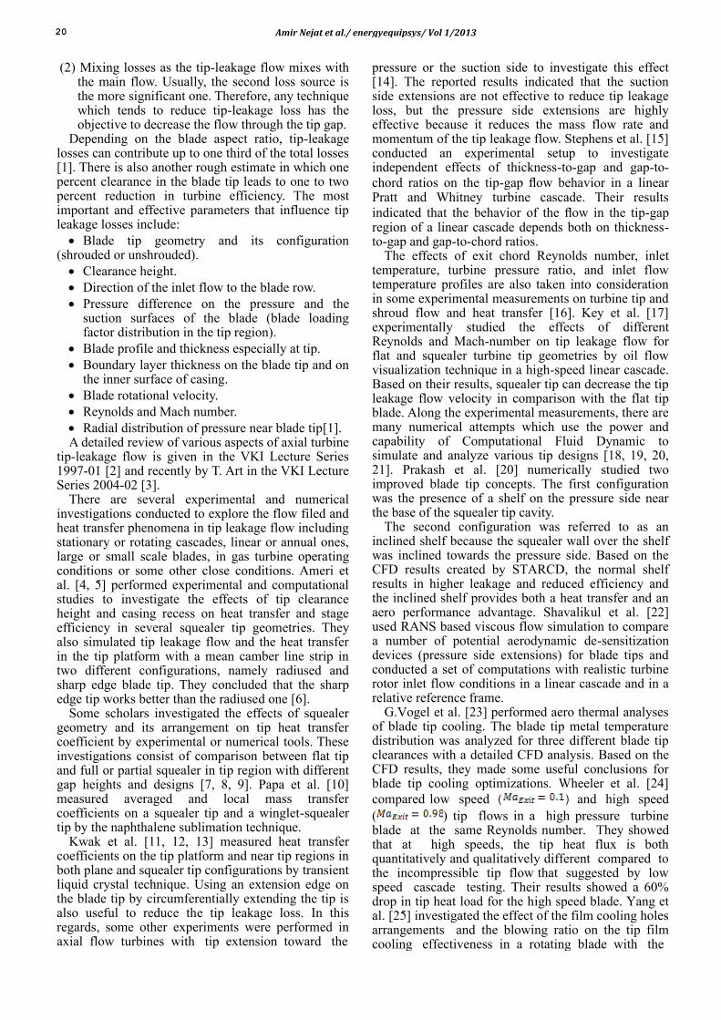
10 different tip designs created to investigate their tip leakage loss include: 1- Baseline, 2- Tip injection, 3- Flat tip with 3 mm gap height, 4- Flat tip with 6 mm gap height, 5- PS Squealer, 6- SS Squealer, 7-Double Squealer, 8- PS Extension, 9- SS Extension, and 10- Double Extension. As shown in Fig.2 the baseline case has partial squealer on blade tip presser side and full one on suction side. It should also mentioned that coolant hole for tip injection case is located in the leading edge region of the blade tip. The computational domain for both stator and rotor consists of two sub-domains with different element types. The first one is viscous domain that is adjacent to the blade walls and it includes pressure and suction side, blade tip and blade hub and outer casing. T-Grid© is used to create prisms elements as the boundary layer mesh for this subdomain. This subdomain includes 10 layers with the first layer height equals to 0.01 mm. This gave an average value of Y+ <5 on the blade walls. Therefore, this computational mesh is suitable for the (SST) k-ω turbulence model.
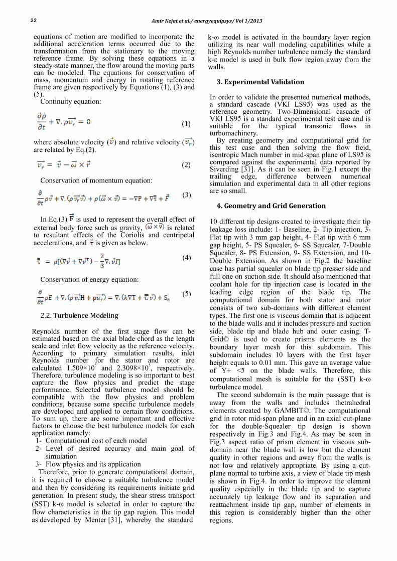
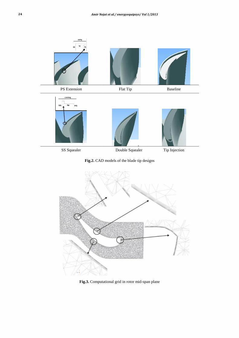
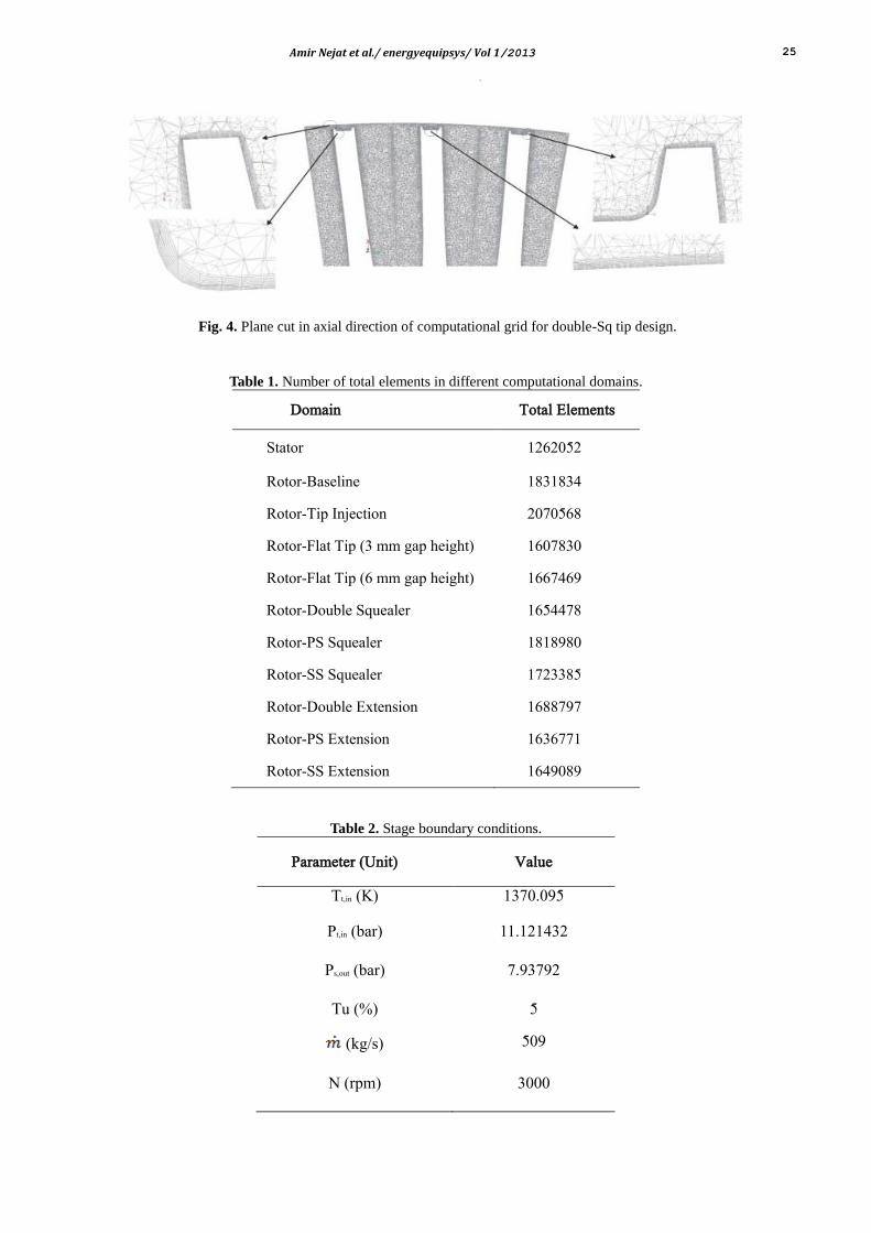
The second subdomain is the main passage that is away from the walls and includes thetrahedral elements created by GAMBIT©. The computational grid in rotor mid-span plane and in an axial cut-plane for the double-Squealer tip design is shown respectively in Fig.3 and Fig.4. As may be seen in Fig.3 aspect ratio of prism element in viscous sub-domain near the blade wall is low but the element quality in other regions and away from the walls is not low and relatively appropriate. By using a cut-plane normal to turbine axis, a view of blade tip mesh is shown in Fig.4. In order to improve the element quality especially in the blade tip and to capture accurately tip leakage flow and its separation and reattachment inside tip gap, number of elements in this region is considerably higher than the other regions.

Amir Nejat et al./ energyequipsys/ Vol 1/2013 23
To find the suitable grid density, a grid independency study is performed. This process is checked by comparing the solutions of the flat tip design (3 mm gap height) with 5 different grid densities which have 664185, 1090644, 1229226, 1620872 and finally 2457865 elements. The main reason for choosing flat tip design for grid independency study is that the grid generation process with various node densities on all edges of this case and control of this process is easier than the other cases. So when the appropriate node and mesh density on edges and surfaces of corresponding case is determined by grid independency study, this mesh density algorithm will be applied on other cases. Based on the simulation results, it can be concluded that if grid density algorithms applied to 1090644 element case is exceeded, the solution becomes grid independent. In Table 1, the number of total elements created for each domain related to various tip design is reported.
5. Boundary Conditions Total pressure and temperature, flow angle which is normal to the stator inlet plane and the turbulence properties are specified at inlet boundary. Static pressure is used to set the outlet boundary condition.
The computational domain covers only one stator and one rotor blade passage and as a consequent, periodic rotational boundaries are enforced at circumferential direction. A no slip boundary condition is applied at the casing end wall, blade hub and on the blade surface. In Table 2, imposed boundary conditions are represented.
6. Convergence of Solution The solution is assumed to be converged when the residuals of continuity equation, the X, Y and Z momentum equations and turbulence properties decreased by at least 3 order of magnitude. If, however, at this situation, the values of residuals are still changed, it will be required to continue simulation until the residuals reached to a fixed value. In addition, the mass-averaged of some specific fluid properties such as static or total pressure or temperature at the exit plane of rotor and finally the outlet mass flow rate are monitored to make sure for solution convergence. At least two thousand iterations are necessary to reach the convergence criteria for all case studies.
7. Results and Discussions By using mixing plane technique to capture stator-rotor interactions and to couple stator and rotor domain boundary conditions, the fluid flow in the first stage of a typical gas turbine is numerically solved. The simulation results of baseline case in mid-span plane are shown in Fig.5.
These results include total and static pressure and temperature, entropy generation and velocity magnitude. As it can be seen in Fig.5, the total temperature does not change in the stator because stator walls are assumed adiabatic. It is also shown that static temperature is increased in the stator trailing edge region, and as a consequent it is required to design and use trailing edge cooling to decrease temperature. Total pressure is fixed in the whole stator domain except in downstream of its trailing edge.
Fig. 1. Comparison between experimental data and simulation results.
24 Amir Nejat et al./ energyequipsys/ Vol 1/2013
PS Extension Flat Tip Baseline
SS Squealer Double Squealer Tip Injection
Fig.2. CAD models of the blade tip designs
Fig.3. Computational grid in rotor mid-span plane
Amir Nejat et al./ energyequipsys/ Vol 1/2013 25
Fig. 4. Plane cut in axial direction of computational grid for double-Sq tip design.
Table 1. Number of total elements in different computational domains.
Domain Total Elements
Stator 1262052
Rotor-Baseline 1831834
Rotor-Tip Injection 2070568
Rotor-Flat Tip (3 mm gap height) 1607830
Rotor-Flat Tip (6 mm gap height) 1667469
Rotor-Double Squealer 1654478
Rotor-PS Squealer 1818980
Rotor-SS Squealer 1723385
Rotor-Double Extension 1688797
Rotor-PS Extension 1636771
Rotor-SS Extension 1649089
Table 2. Stage boundary conditions.
Parameter (Unit)
Value
Tt,in (K) 1370.095
Pt,in (bar) 11.121432
Ps,out (bar) 7.93792
Tu (%) 5
(kg/s) 509
N (rpm) 3000

26 Amir Nejat et al./ energyequipsys/ Vol 1/2013
Static Temperature (K) Total Temperature (K)
Static Pressure (pa) Total Pressure (pa)
Entropy Velocity Magnitude (m/s)
Fig. 5. First stage result simulations in the mid-span plane.
Total pressure reduction in the trailing edge is due to mixing between the pressure and suction side flows. The entropy generation is high in the aft portion of the stator suction side due to boundary layer increment and in the trailing edge because of mixing flow. The stator throat contains the highest magnitude of velocity.
The static pressure distribution in blade tip platform is illustrated in Fig.6. As shown in Fig.6 after the PS-Squealer, pressure dropped due to flow separation and the SS-Squealer increases, pressure level on the blade tip region. Static pressure distributions on pressure and suction sides of the blade tip for different tip designs are shown in Fig.7. This figure shows that using tip injection does not affect the pressure distribution in pressure side edge while causes to increase pressure in suction side edge in comparison with the baseline. Therefore, pressure difference
across the blade tip in the tip injected rotor is lower than the baseline and consequently has lower tip leakage flow.
The results presented in Fig.7 show that the blade tip modification by adding full or partial squealer or extension rims on the pressure or the suction side edges of the blade tip affect tip pressure distribution and cause to decrease the pressure in comparison with baseline, while injection in the blade tip increases the pressure level especially on the suction side edge.
It is transparently obvious from Fig.6 and Fig.7 that the pressure level for the flat tip rotor with 3 mm gap height are the highest among all the case studies, while its pressure difference across the blade tip is not so significant.
Although this design (flat tip with 3 mm gap) has the highest pressure level in its blade tip, it does not represent the best performance.

Amir Nejat et al./ energyequipsys/ Vol 1/2013 27
Baseline Double Squealer Tip injection SS-Squealer PS-Squealer
Double Ext SS Extension PS Extension Flat tip, 3 mm Flat tip, 6 mm
Fig. 6. Static pressure distribution in blade tip platform.
Fig. 7. Static pressure distribution on PS and SS edges of the blade tip in various tip designs.

28 Amir Nejat et al./ energyequipsys/ Vol 1/2013
In Fig.8 static temperature distribution in the blade tip platform is illustrated. As you can see in Fig.8 high temperature regions in baseline, PS-Squealer and SS-Squealer designs are along their squealers or rims. It is also shown that adding extensions on either sides of the blade tip does not affect temperature distribution on the blade tip platform, but coolant flow injection especially at the leading edge region of the blade tip influences blade tip up to its mid-chord. It also will be shown that the tip injection design has slightly better total pressure efficiency than the baseline design. Therefore, in aero-thermal aspect of view, tip injection design experiences lower temperature and heat load and higher efficiency and consequently, it represents durable and reliable performance. Difference between streamline patterns in the blade tip for various designs is shown in Fig.9. This figure clearly illustrates those regions where tip leakage vortex created and developed to downstream of the blade trailing edge. This vortex is created from the mid-chord region in the suction side edge of the
blade, and then develops through the passage and mixes with the trailing edge vortex. Total pressure loss coefficients is defined as , where
and are respectively mass-averaged of relative total pressure at the inlet and outlet planes of the rotor domain, is the local total pressure and
is the mass-averaged of static pressure at the outlet plane [19]. The total pressure loss coefficient distribution in different axial planes for baseline rotor is shown in Fig.10. In this figure, tip leaking vortex migration in axial direction is shown in various axial planes. As you can see in Fig.10 the strength and distribution of tip leakage vortex is decreased along the axial direction. Averaged total pressure loss
coefficient for various tip designs in two axial planes is reported in Table 3. The results of this table show that averaged total pressure loss coefficient is decreased along the axial direction. It also should be noted that coolant injection decreases loss while using double squealer increases it.
Baseline Tip injection Flat tip, 6 mm
Double Ext SS-Squealer PS-Squealer
Fig. 8. Static temperature distribution in the blade tip platform.
Tip injection Baseline Flat tip, 3 mm Double Squealer
Fig. 9. Streamline patterns in different designs.

Amir Nejat et al./ energyequipsys/ Vol 1/2013 29
The highest loss associated with tip leakage vortex observed in the SS-Squealer tip design.
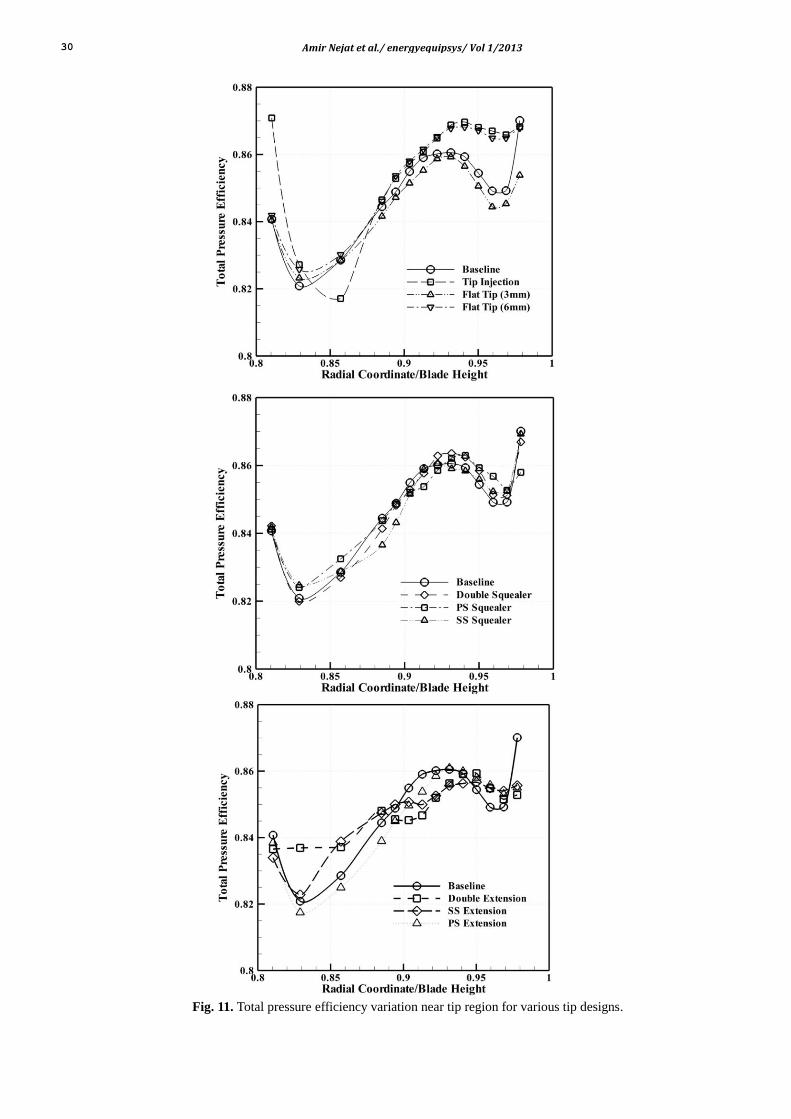
Total pressure efficiency is defined as Y=(P0i-P0o)/(P0i-Po).
Total pressure efficiency variation near tip region for various tip designs is illustrated in Fig.11. Minimum total pressure efficiency in all cases occurs
between 0.8 and 0.85 blade height. This is due to tip leakage vortex formation. Total pressure efficiency improvement of the tip injection compared to the baseline case especially near tip region demonstrates potential capability of this design along with its thermal advantages.
0.9 Axial Chord 0.8 Axial Chord
Rotor Exit Plane Blade Trailing Edge
Fig. 10. ξ Distribution in various axial planes.
Table 3. Averaged Total Pressure Loss Coefficients .
Case Study
Baseline 0.1839 0.1783
Tip injection 0.1773 0.1736
Double squealer 0.1844 0.1811
Double Extension 0.1738 0.1704
Flat tip (3 mm gap height) 0.1888 0.1836
Flat tip (6 mm gap height) 0.1723 0.1698
PS Squealer 0.1774 0.1729
PS Extension 0.1792 0.1735
SS Squealer 0.1873 0.1836
SS Extension 0.1756 0.1727
30 Amir Nejat et al./ energyequipsys/ Vol 1/2013
Fig. 11. Total pressure efficiency variation near tip region for various tip designs.

Amir Nejat et al./ energyequipsys/ Vol 1/2013 31
Finally, in order to compare performance of various tip designs, total pressure efficiency of different tip designs are represented in Table 4. Presented data of Table 4 reveals that active tip leakage controls via coolant tip injection has a minor enhancement in total pressure efficiency in comparison with baseline, but this is only in aerodynamic aspect of view. The only geometrical difference between baseline and double squealer blade is that baseline case has partial squealer on pressure side and full squealer on suction side of its tip while in double squealer case both PS and SS squealer are full. Based only on aerodynamic aspect of view that is reported in Table 4, using partial squealer on the pressure side of the blade tip (baseline case) slightly improves stage performance in comparison with using full PS squealer in double squealer design. Another useful comment derived from presented data is that the lowest total pressure efficiencies are related to blade extension features, whether the extension is applies to the pressure side, suction side or both sides of the blade tip. By comparing aerodynamic performances of flat tip designs with various tip gaps, it can concluded that reduction in tip clearance height could increase stage efficiency due to decrease in tip leakage mass flow and weaken the strength of corresponding vortex in the blade suction side.
8. Conclusions Tip leakage flow on different tip configurations are examined by numerical simulation in realistic engine operating conditions and in a real geometry of the first stage of a heavy duty gas turbine. These tip configurations include flat tip with two different gap heights, a single pressure-side squealer tip, a single suction-side squealer tip, a double full squealer tip, a single pressure-side extension, a single suction-side extension tip, a double extension tip, full suction-side
and partial pressure-side squealer tip, and finally a double squealer with tip injection.
The major advantages of this study are to investigate performance of both active and passive leakage controls in a real gas turbine and to consider the effects of stator flow field on the rotor tip leakage using mixing plane approach. The formation of tip leakage vortex in mid-chord region of the blade suction side and migrating to the blade trailing edge influences the pressure distribution in the blade suction side especially in near tip region. Tip leakage flow also causes to reduce blade pressure ratio or blade loading factor especially in tip region. In fact, tip leakage reduces pressure difference in tip region by leaking from the pressure to the suction side of the blades. In other words, in clearance region, static pressure level at the pressure side is decreased while this parameter is increased in the suction side and corresponding pressure difference is reduced.
The simulation results show that averaged total pressure loss coefficient is decreased along the axial direction. This reveals that the strength of tip leakage vortex is decreased by approaching to the rotor outlet plane. Total pressure efficiency is used to compare the aerodynamic performance of different tip leakage controls. The presented results indicate that using partial squealer in the pressure side instead of full one has slightly better performance. It also shows that a single full suction-side squealer has higher total pressure efficiency in comparison with a single full pressure-side squealer. The static pressure distribution on the blade tip indicates that using a single full squealer on the suction-side of the blade tip strongly increases the pressure level in this region. In single pressure-side full squealer, the tip flow separates at the squealer and by reattaching in the blade tip increases blade tip heat transfer coefficient. The results of numerical simulations reveal that using tip extension on each side of the blade tip or on both side of it does not improve aerodynamic performance of the stage.
Table 4. Total Pressure Efficiency for Each Case.
Case Study
Y
Baseline 0.8426
Tip injection 0.8427
Double squealer 0.8420
Double Extension 0.8244
Flat tip (3 mm gap height) 0.8360
Flat tip (6 mm gap height) 0.8324
PS Squealer 0.8347
PS Extension 0.8228
SS Squealer 0.8418
SS Extension 0.8246
32 Amir Nejat et al./ energyequipsys/ Vol 1/2013
It was also shown that increasing the tip gap height, causes to increase tip leakage flow and corresponding loss. Finally, by comparing the performance of all active and passive tip designs, it can concluded that the full suction-side and partial pressure-side tip equipped with tip injection has the best performance in both aerodynamic and heat transfer aspects of view.
Acknowledgments
The authors would like to thank all the people from Vehicle, Fuel and Environment Research institute involved in the work for their contribution and useful suggestions.
Nomenclature
Non-dimensional distance from solid wall
Density
Time
Static temperature
Static pressure
Mach Number
absolute velocity
Angular velocity
Position vector from the origin of the rotating frame
External body force
Stress tensor
Molecular viscosity
Unit tensor
Internal energy
Total enthalpy
Whirl velocity
Source terms for energy equation
Shear stress transport
Suction side
Pressure side
Squealer rim at the blade tip
Total pressure loss coefficient
Total pressure efficiency
Subscripts
A Axial Direction
Stagnation state, Local state
Inlet, Outlet
Reference frame, relative
References
[1] Denton, J.D., 1993, “Loss Mechanisms in Turbomachines”, ASME Journal of Turbomachinery, Vol. 115,pp. 621 – 656
[2] Sjolander, S.A., 1997, “Secondary and Tip-Clearance Flows in Axial Turbines”, VKI Lecture Series LS 1997-01.
[3] Arts, T., 2004, “Turbine Blade Tip Design and TipClearance Treatment”, VKI Lecture Series LS 2004-02.
[4] Ameri, A.A., Bunker, R.S., and Bailey, J.C., “Heat Transfer and Flow on the First –Stage Blade Tip of a Power Generation Gas Turbine: Part 1-Experimental Results”, Journal of Turbomachinery, 122:263-271, April 2000.
[5] Ameri, A.A., Bunker, R.S., and Bailey, J.C., “Heat Transfer and Flow on the First –Stage Blade Tip of a Power Generation Gas Turbine: Part 2-Simulation Results”, Journal of Turbomachinery, 122:272-277, April 2000.
[6] Ameri, A.A., “Heat Transfer and Flow on the Blade Tip of a Gas Turbine Equipped with a Mean-Camberline Strip”, Tech. Rep., NASA/CR, AYT Corporation, Brook Park, Ohio, May 2001.
[7] Camci, C., Dey, D., Kavurmacioglu, L., “Tip Leakage Flows near Partial Squealer Rims in an Axial Flow Turbine Stage”, ASME GT2003-3897.
[8] Azad, Gm.S., Han, J.C., Boyle, R.J., “Heat Transfer and Flow on the Squealer Tip of a Gas Turbine Blade”, ASME 2000-GT-195.
[9] Azad, Gm. S., Han, J.C., Bunker, R.S., Lee, C.P., 2002, “Effect of Squealer Geometry Arrangement on a Gas Turbine Blade Tip Heat Transfer”, Journal of Heat Transfer, 124, pp. 452-459.
[10] Papa, M., Goldstein, R.J., Gori, F., 2002, “Effects of Tip Geometry and Tip Clearance on the Mass/Heat Transfer From a Large-Scale Gas Turbine Blade”, ASME GT-2002-30192.
[11] Kwak, J.S., Ahn, J., Han, 2002, “Heat Transfer Coefficient on a Gas Turbine Blade Tip and Near Tip Regions”, AIAA-2002-3012.
[12] Kwak, J.S., Ahn, J., Han, 2002, “Heat Transfer Coefficient on the Squealer Tip and Near Squealer Tip Regions of a Gas Turbine Blade”, IMECE 2002-31109.
[13] Kwak, J.S., Ahn, J., Han, J.C., Lee, C.P., Boyle, R., Gaugler, R., R.Bunker, 2003, “Heat Transfer Coefficient on the Squealer Tip and Near Tip Region of a Gas Turbine Blade with Single Squealer”, ASME GT2003-38907.
[14] Dey, D., Camci, C., “Aerodynamic Tip Desensitization of an Axial Turbine Rotor using Tip Platform Extensions”, ASME 2001-GT-0484.

Amir Nejat et al./ energyequipsys/ Vol 1/2013 33
[15] Stephens, J.,Corke, T., and Morris, S., “Turbine Blade Tip Leakage Flow Control: Thick/Thin Blade
[16] Polanka, M.D., Hoying, D.A., Meininger, M., MacArthur, C.D., “Turbine Tip and Shroud Heat Transfer and Loading. Part A: Parameter Effects including Reynolds Number, Pressure Ratio, and Gas to Metal Temperature Ratio”, ASME GT-2002-30186
[17] Key, N.L., Arts, T., “Comparison of Turbine Tip Leakage Flow for Flat Tip and Squealer Tip Geometries at High-Speed Conditions”, Journal of Turbomachinery. 2006, Vol.128, 213-220
[18] Wei, L., Weiyang, Q., and Hualing, L., “Numerical Simulation of Tip Clearance Controls in Axial Turbine Rotor, Part 1: Active Flow Injection from Turbine Blade Tip”, Proceeding of ASME Turbo Expo 2008: Power for Land , Sea and Air, June9-13 2008.
[19] Wei, L., Weiyang, Q., Kaifu, X.,Hualing, L., “Numerical Simulation of Tip Clearance Controls in Axial Turbine Rotor Part2: Passive Control of Five Different Tip Platforms”, In Proceeding of ASME Turbo Expo 2008: Power for Land, Sea and Air, June9-13 2008.
[20] Prakash, C., Lee, C.P., Cherry, D.G., Doughty, R., Wadia, A.R., “Analysis of Some Improved Blade Tip Concepts”, Journal of Turbomachinery. 2006, Vol.128,639~642.
[21] McCarter, A.A., Xiao, X., Lakshminarayana, B., “Tip clearance effects in a turbine rotor. Part 1: Velocityfield and flow physics”, ASME 2000-GT-0476.
[22] Shavalikul, A., Camci, C., “A Comparative Analysis of Pressure Side Extensions for Tip Leakage Control in Axial Turbines”, ASME GT2008-50782.
[23] Vogel, G., Agrawal, A., Nannapaneni, P.,”Turbine Blade Tip Cooling Modeling and Optimization”, ASME GT2009-59244.
[24] Wheeler, A., P., S., Atkins, N., R., He, L.,”Turbine Blade Tip Heat Transfer In Low Speed And High Speed Flows”, ASME GT2009-59404.
[25] Yang, D., Feng, Z., Yu, X.,” Investigation of Film Cooling Effectiveness on Squealer Tip of a Gas Turbine Blade”, ASME GT2009-60280.
[26] Granovskiy, A., Kostege, M., Lomakin, N.,” Parametrical Investigation of Turbine Stages with Open Tip Clearance for the Purpose of Stage Efficiency Increase”, ASME GT2009-22876.
[27] Schabowski, Z., Hodson, H., Giacche, D.,Power, B., and Stokes, M.,” Aeromechanical Optimization of
a Winglet-Squealer Tip for an Axial Turbine”, ASME GT2010-23542.
[28] Wheeler, A.P.S., Korakianitis, T., Banneheke, S.,” Tip Leakage Losses in Subsonic and Transonic Blade Rows”, ASME GT2011-45798.
[29] Shyam, S., Ameri, A.,”Comparison of Various Supersonic Turbine Tip Designs to Minimize Aerodynamic Loss and Tip Heating”, ASME GT2011-46390
[30] Menter, F.R., “Two-Equation Eddy-Viscosity Turbulence Model for Engineering Applications”, AIAA Journal, 32(8):1598-1605, August 1994
[31] Siverding, C., “Test Case 1: 2-D Transonic Turbine Nozzle Blade”, Tech Rep., Von Karman Inst. For Fluid Dynamics Lecture Series 1982-05, Rhode Saint Genese, Belgium, April 26-30 1982
[32] FLUENT 6.3 documentation, User’s Guide, FLUENT Inc

34 Amir Nejat et al./ energyequipsys/ Vol 1/2013