Application of Mechanical Arm Systems to Reduce Injuries ...
Prepared by the Health and Safety Laboratory for the Health and Safety Executive 2015
Health and Safety Executive
Assessment of the arm locking systems of two-post vehicle lifts
RR1030Research Report

Paul Woody and Alan McDonaldHealth and Safety LaboratoryHarpur HillBuxtonDerbyshire SK17 9JN
Following a number of instances of vehicles falling from two-post vehicle lifts, the Health and Safety Executive (HSE) became concerned that some lifts available for sale in the United Kingdom (UK) may not be fit for purpose due to inferior build quality and or design. A particular area of concern identified by HSE was the locking systems used to secure the carrying arms during lifting operations.
The purpose of this research was to investigate whether a selection of typical two-post vehicle lifts forming a cross-section of what was available on the UK market (at the time the research was instigated), complied with the requirements of paragraph four of section 5.9.5 in BS EN 1493:2010.
Only three out of the seven lifts tested met the requirements of paragraph four of section 5.9.5 of BS EN 1493:2010. Of these three, only one (out of five) used a gear and block locking system. The remaining two lifts (out of two) utilised an interlocking circular gears system.
This report and the work it describes were funded by the Health and Safety Executive (HSE). Its contents, including any opinions and/or conclusions expressed, are those of the authors alone and do not necessarily reflect HSE policy.
Assessment of the arm locking systems of two-post vehicle lifts
HSE Books
Health and Safety Executive

© Crown copyright 2015
First published 2015
You may reuse this information (not including logos) free of charge in any format or medium, under the terms of the Open Government Licence. To view the licence visit www.nationalarchives.gov.uk/doc/open-government-licence/, write to the Information Policy Team, The National Archives, Kew, London TW9 4DU, or email [email protected].
Some images and illustrations may not be owned by the Crown so cannot be reproduced without permission of the copyright owner. Enquiries should be sent to [email protected].
Acknowledgements
The authors would like to express their gratitude to the Garage Equipment Association (GEA) and its members for their support during the testing programme, as well as to all the manufacturers and distributers who assisted with the provision of two-post vehicle lifts used for testing.
ii

iii
EXECUTIVE SUMMARY
Following a number of instances of vehicles falling from two-post vehicle lifts, the Health and Safety Executive (HSE) became concerned that some lifts available for sale in the United Kingdom (UK) may not be fit for purpose due to inferior build quality and or design. A particular area of concern identified by HSE was the locking systems used to secure the carrying arms during lifting operations.
The relevant British and European (BS EN) standard for the two-post vehicle lifts, BS EN 1493: 20101 Vehicle Lifts, defines the performance criteria for these carrying arm locking systems in section 5.9.5 paragraph four as follows:
“Arm locking systems shall be designed to resist a force of 4.5% of the capacity of the lift
without permanent deformation, or to resist a force of 6.75% of the capacity without breakage.
The forces used however shall not be less than 1500N and 2250N respectively. Forces are
assumed to act horizontally at the load carrying points, and in the most unfavourable direction,
with the arms fully extended.”
Objectives
The purpose of this research was to investigate whether a selection of typical two-post vehicle lifts forming a cross-section of what was available on the U.K. market (at the time the research was instigated), complied with the requirements of paragraph four of section 5.9.5 in BS EN 1493:20101.
While it was agreed that the lifts selected for testing should be representative of the cross section of those available for sale in the U.K, it was also agreed that particular efforts should be made to obtain at least one example of the poorest quality lift available.
The evidence that this study provides can be used to inform opinion concerning the interpretation and practicalities in referring to and applying paragraph 5.9.5 to two-post vehicle lifts under test.
Test Set-up
Two load tests were conducted (per vehicle lift) with an applied load that was 4.5% (test-1) and 6.75% (test-2) of the vehicle lifts rated SWL (Safe Working Load) respectively, unless, the load calculated from the vehicle lifts SWL fell below the prescribed minimum forces stipulated in BS EN 1493:20101 of 1500N (153Kgf) for the 4.5% test, and 2250N (229Kgf) for the 6.75% test.
The load was applied to the carrying arm using a hand winch, with a 2-tonne tensile indicating load cell used to measure the amount of force being applied.
iv
Main Findings
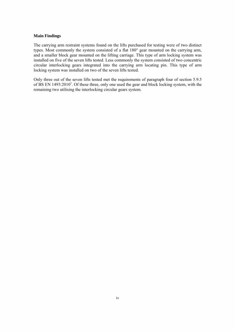
The carrying arm restraint systems found on the lifts purchased for testing were of two distinct types. Most commonly the system consisted of a flat 180° gear mounted on the carrying arm, and a smaller block gear mounted on the lifting carriage. This type of arm locking system was installed on five of the seven lifts tested. Less commonly the system consisted of two concentric circular interlocking gears integrated into the carrying arm locating pin. This type of arm locking system was installed on two of the seven lifts tested.
Only three out of the seven lifts tested met the requirements of paragraph four of section 5.9.5 of BS EN 1493:20101. Of these three, only one used the gear and block locking system, with the remaining two utilising the interlocking circular gears system.

v
CONTENTS
ACKNOWLEDGEMENTS ............................................................... II
EXECUTIVE SUMMARY ................................................................ III
1. TABLE OF FIGURES ............................................................. 1
2. INTRODUCTION .................................................................... 2
3. DESCRIPTION OF A TYPICAL TWO-POST VEHICLE LIFT. 3
3.1 Overview of carrying Arm Locking systems 4 3.1.1 180° Gear and Block Gear System ............................................................. 4 3.1.2 360° Interlocking System ........................................................................... 5
4. TWO-POST VEHICLE LIFTS (SAMPLES TESTED).............. 7
5. METHODOLOGY ................................................................... 9
5.1 Design of Experiment 9 5.2 Equipment USed 9 5.3 Test Setup 10
6. RESULTS............................................................................. 12
6.1 Individual Results 13 6.1.1 VL-1 ......................................................................................................... 13 6.1.2 VL-2 ......................................................................................................... 15 6.1.3 VL-3 ......................................................................................................... 17 6.1.4 VL-4 ......................................................................................................... 19 6.1.5 VL-5 ......................................................................................................... 21 6.1.6 VL-6 ......................................................................................................... 23 6.1.7 VL-7 ......................................................................................................... 24
7. OBSERVATIONS ................................................................. 26
8. DISCUSSION ....................................................................... 27
9. CONCLUSIONS ................................................................... 29
10. RECOMMENDATIONS ........................................................ 30
10.1 Recommendations for the Locking System 30 10.2 Recommendations for the Standard 31
11. REFERENCES ..................................................................... 32
1
1. TABLE OF FIGURES
Figure 1: CAD image - showing the layout of a typical two-post vehicle lift .............................. 3 Figure 2: CAD image - showing the 180° Gear and Block Gear System ..................................... 4 Figure 3: CAD image - overview of a 360° interlocking system vehicle lift ................................ 5 Figure 4: CAD image - showing an exploded view of the 360° system ....................................... 5 Figure 5: CAD image - showing how the carrying arm is secured to the locking system ............ 6 Figure 6: CAD image - showing how the 360° interlocking system operates .............................. 6 Figure 7: Drawing - showing the test layout (viewed from above) ............................................. 10 Figure 8: Pre test-1 condition of the carrying arm locking gears (VL-1) .................................... 13 Figure 9: Post test-1 condition of the carrying arm gear (VL-1) ................................................. 13 Figure 10: Post test-1 condition of the locking block (VL-1) ..................................................... 14 Figure 11: Post test-2 condition of the gears (VL-1) ................................................................... 14 Figure 12: Showing the engagement of the locking gear (VL-2) before test-1 ........................... 15 Figure 13: Post test-1 condition of the carrying arm gear (VL-2) ............................................... 15 Figure 14: Post test-1 condition of the locking block (VL-2) ..................................................... 16 Figure 15: Post test-2 condition of the gears (VL-2) ................................................................... 16 Figure 16: CAD image showing a carrying arm attachment method similar to that of VL-3 ..... 17 Figure 17: Post test-1 condition of the locking block (VL-3) ..................................................... 18 Figure 18: Post test-1 condition of the carrying arm gear (VL-3) ............................................... 18 Figure 19: Post test-2 condition of the gears (VL-3) ................................................................... 18 Figure 20: Engagement of the locking gears (VL-4) prior to test-1 ............................................ 19 Figure 21: Post test-1 condition of the arm gear (VL-4) ............................................................. 19 Figure 22: Post test-1 condition of the locking block (VL-4) ..................................................... 20 Figure 23: Post test-2 condition of the gears (VL-4) ................................................................... 20 Figure 24: showing the quality of locking gear engagement (VL-5) before test-1 ..................... 21 Figure 25: Post test-1 (8.8 grade bolts) condition of the locking block (VL-5) .......................... 21 Figure 26: Post test-1 (8.8 grade bolts) condition of the carrying arm gear (VL-5) ................... 22 Figure 27: Post test-2 (8.8 grade bolts) condition of the locking block (VL-5) .......................... 22 Figure 28: Post test-2 (8.8 grade bolts) condition of the carrying arm gear (VL-5) ................... 22 Figure 29: Quality of VL-6 locking system (manufacture and engagement) .............................. 23 Figure 30: Sheared securing dowels (VL-6) ............................................................................... 23 Figure 31: Comparison of VL-7 and VL-6 locking system ........................................................ 24 Figure 32: Notches in the pin and spur gear (VL-7) ................................................................... 24

2
2. INTRODUCTION
The Health and Safety Executive (HSE) have recently become concerned that a significant number of two-post vehicle lifts currently available on the British market maybe failing to meet some of the requirements of the relevant standard BS EN 1493:20101 ‘Vehicle Lifts’. The HSE’s interest was raised after seeing an increase in the number of incidents involving two-post vehicle lifts, with the main area of concern relating to the design and build quality of the locking system used to restrain the carrying arms and prevent their movement during lifting operations.
Paragraph four of section 5.9.5 of BS EN 1493:20101 states that the “Arm locking systems shall
be designed to resist a force of 4.5% of the capacity of the lift without permanent deformation,
or to resist a force of 6.75% of the capacity without breakage.”
The purpose of this research was to investigate whether a selection of two-post vehicle lifts forming a cross-section of what was available on the U.K. market (at the time the research was instigated), complied with the requirements of paragraph four of section 5.9.5.
A programme of testing was established to load the carrying arm locking system of seven two-post vehicle lifts in accordance with BS EN 1493:20101. The performance of each vehicle lift tested was assessed and evaluated against the criteria specified in paragraph four of section 5.9.5 BS EN 1493:20101. It was intended to test a greater number than this, but as the project developed, some imported vehicle lifts became difficult to source and hence were unavailable for testing. Upon completion of the project such manufacturers appear not to have a visible presence in the U.K. market.
Over the duration of the project, several attempts were made by HSL, the GEA, and individual members of the GEA working on behalf of HSL to obtain an example of a poor quality lift. All of these attempts were unsuccessful. Similarly, orders placed with reputable suppliers for budget model vehicle lifts were delayed and subsequently filled with alternative lifts of better quality. Despite significant effort, an example of a poor quality lift could not be purchased from any company or sole trader engaged in the sale of new two-post vehicle lifts that were approached by HSL or individuals working on behalf of HSL.
The results of this research can be used to inform opinion concerning the interpretation and practicalities in referring to and applying section 5.9.5 to the vehicle lifts under test.
The vehicle lifts tested were anonymised to prevent identification of the manufacturer or distributer.

3
3. DESCRIPTION OF A TYPICAL TWO-POST VEHICLE LIFT
Figure 1: CAD image - showing the layout of a typical two-post vehicle lift
As shown in Figure 1, a typical two-post vehicle lift consists of two opposing vertical posts located a suitable distance apart to allow a vehicle to be positioned in between for lifting. Each post has two telescopic carrying arms situated either side of the lifting carriage that can be extended and rotated around the Z-axis, allowing for correct positioning of the pick-up pads underneath the vehicle that is to be lifted. Some of the lifts tested had telescopic carrying arms of unequal lengths, for the purpose of making it easier for the operator to locate the correct lifting point.
The majority of the vehicle lifts tested used a similar type of electro-hydraulic system to drive the lifting carriage up and down the vertical post.
The lifts were operated using a rotary switch located on one of the posts. The lifting carriage provided the vertical movement for the lift and was controlled by a hydraulic ram located inside the post that acted on a set of chains and pulleys, which in turn lifted the carriage. To prevent against asymmetric lifting, there was an equaliser cable that ran between the two lifting posts. The cable ran through pulleys located at the top of the two lifting posts, and attached to both of the lifting carriages.
To prevent against unintended lowering of the vehicle lift in the event of failure of the electro-hydraulic mechanism, a safety catch is located at specific heights on the lift post.
Vertical post
Lifting carriage
Telescopic carrying arm
Pick-up pad

5
3.1.2 360° Interlocking System
Figure 3: CAD image - overview of a 360° interlocking system vehicle lift
Two of the vehicle lifts tested, used an interlocking circular gears system of similar design to that seen in Figure 3. This method combines the carrying arm, locking gears, and securing pin into one system. Figure 4 shows the main components of the locking system.
Figure 4: CAD image - showing an exploded view of the 360° system
Lifting carriage
Locking system
Carrying arm
Locking ring
Carrying arm securing dowels
Carrying arm securing pin
Return spring
Spur gear
Locking ring carrier

4
Previous incidents involving two-post vehicle lifts have highlighted concerns regarding the locking system used to restrain the carrying arms against unintended movement during lifting operations.
This testing programme focused specifically on the type and quality of carrying arm locking systems used by the different vehicle lift manufacturers; and in particular whether they complied with the requirements of paragraph four - section 5.9.5 of BS EN 1493:20101.
3.1 OVERVIEW OF CARRYING ARM LOCKING SYSTEMS
3.1.1 180° Gear and Block Gear System
As shown in Figure 2, the common practice for securing the carrying arms is through using a toothed locking block (located on the lifting carriage) and a corresponding gear located on the carrying arm. Pertinent differences in the alternative locking system designs can be seen in Section 4: Table 1 – Samples Tested.
The carrying arm is secured in its desired position by first raising the locking block (which is attached to a pin located through the top of the lifting carriage), which in-turn releases the carrying arm, allowing it to be moved into the desired position under the vehicle. Once the correct position has been found, the locking block can then be lowered, engaging with the carrying arm gear and securing the carrying arm. A return-spring located around the locking block pin aids with locating the locking block in the correct position, and helps to prevent the locking block from disengaging prior to lifting the vehicle.
Figure 2: CAD image - showing the 180° Gear and Block Gear System
The 180° gear and block gear system described above was the most common form of locking system encountered during the testing programme.
Locking block pin
Carrying arm locking gear
Carrying arm pin
Carrying arm
Locking block
Locking block return spring

6
Figure 5: CAD image - showing how the carrying arm is secured to the locking system
As can be seen in Figure 5, the carrying arm is secured to the locking system via 2 or 3 dowels (depending on the lifts SWL) which locate through the carrying arm and into the locating pin.
Figure 6: CAD image - showing how the 360° interlocking system operates
As can be seen in Figure 6, the locking system is operated by lifting up the locking ring carrier (and locking ring) from the recess on the top of the lifting carriage. This releases the carrying arm, such that it can be rotated into the desired position. Once correctly positioned, the locking ring carrier (and locking ring) can then be lowered back into the recess, securing the carrying arm.
Carrying arm locked
Carrying arm unlocked
Recess for securing the locking ring
A A
Securing dowels locate through the carrying arm, securing it to the pin.
Carrying arm
Locking system –carrying arm securing pin

7
4. TWO-POST VEHICLE LIFTS (SAMPLES TESTED)
Table 1: Provides details of the different types of gears encountered during the test programme.
Table 1: Samples tested
HSL
Identifier
SWL
(Kg)
Carrying
arm
locking
method
Image of locking block Image of arm gear
VL-1 4000Kg 180° interlocking
Image (cropped): P1010115 Image (cropped): P1010143
VL-2 4000kg 180° interlocking
Image (cropped): P1010177
Image (cropped): P1010175
VL-3 4000kg 180° interlocking
Image (cropped): P1010179
Image (cropped): P1010181
VL-4 3200kg 180° interlocking
Image (cropped): DSC02079
Image (cropped): DSC02070

8
HSL
identifier
SWL
(Kg)
Carrying
arm
locking
method
Image of locking block Image of arm gear
VL-5 4082Kg 180° interlocking
Image (cropped): DSC02009 Image (cropped): P1010184
VL-6 3200Kg 360° interlocking
Image (cropped): P7110022
Image (cropped): P7110021
VL-7 4000Kg 360°
interlocking
Image (cropped): P711001
Image (cropped): P7110012

9
5. METHODOLOGY
5.1 DESIGN OF EXPERIMENT
BS EN 1493:20101 states that; “arm locking systems shall be designed to resist a force of 4.5%
of the capacity of the lift without permanent deformation, or to resist a force of 6.75% of the
capacity without breakage. The forces used however shall not be less than 1500N and 2250N
respectively. Forces are assumed to act horizontally at the load carrying points, and in the most
unfavourable direction, with the arms fully extended.”
Two load tests were conducted (per vehicle lift) with an applied load that was 4.5% and 6.75% of the rated SWL (Safe Working Load) respectively. This load was applied to the carrying arm using the testing method described in Section 5.3 - Test Setup. Two load tests were conducted (per vehicle lift) with an applied load that was 4.5% (test-1) and 6.75% (test-2) of the vehicle lifts rated SWL (Safe Working Load) respectively, unless, the load calculated from the vehicle lifts SWL fell below the prescribed minimum forces stipulated in BS EN 1493:20101 of 1500N (153Kgf) for the 4.5% test, and 2250N (229Kgf) for the 6.75% test.
A new set of locking gears and arm gear bolts were used, for each of the 4.5% and 6.75% load tests, i.e. two sets of locking gears were used per vehicle lift.
After conducting the load test, each set of locking gears were visually inspected (without the use of a magnifier) for permanent deformation. BS EN 1493:20101 does not specify what type of inspection method should be adopted, when examining for permanent deformation.
5.2 EQUIPMENT USED
The following equipment was used during the testing programme.
Load-cell: A 2-tonne tensile indicating load-cell (Radio-Link Plus manufactured by Straight Point, serial number: 10023, calibration date*: 08/04/2013), was used to measure the applied force to the carrying arm. It had a resolution of 0.001t, permitting the load to be applied in 1Kgf increments.
Hand winch: The hand winch that was used to apply the force to the carrying arm had a breaking strength of 22.8kN. It was securely mounted to an anchor block, which was attached to the HSL - Engineering Laboratory strong floor.
Lenzkes machining clamps: The clamps were used to securely position the base of the vehicle lift post to an anchor plate attached to the strong floor. Four clamps were used in order to mitigate against any possible twisting motion in the post, resulting from the force applied to the carrying arm.
Lifting gear: The overhead crane and appropriately rated lifting slings were used to raise and position the vehicle lift on the anchor plate. A 2-tonne sling was also used to choke through the carrying arm to simplify the attachment of the load cell.
*Calibration is performed in accordance with UKAS Accreditation Standards

10
5.3 TEST SETUP
Figure 7: Drawing - showing the test layout (viewed from above)
The lift to be tested was installed on the anchor plate using the overhead crane and appropriate lifting equipment. Once it had been positioned in the correct orientation, it was then secured to the anchor plate using the Lenzekes machining clamps.
The lifting carriage (that supports the carrying arm during operation) was raised to a suitable working height so that it was in line with the hand winch (therefore preventing any loading discrepancies when conducting the test), and ideally resting on the vehicle lifts inbuilt safety catch. If the safety catch could not be engaged, the lifting carriage was instead chocked up and safely secured using wooden blocks and a hydraulic bottle jack.
Both the carrying arm gears and locking blocks were visually inspected and photographed prior to installation on the vehicle lift under test, so that any defects could be identified and documented before testing commenced.
The carrying arm gears and locking blocks were installed on the carrying arm and lifting carriage (respectively) as per the manufacturer’s instructions. So that the test was representative of what would be found in industry (and each lift afforded the best opportunity to pass), care was taken to ensure that the carrying arm gear was aligned to give the best possible engagement with the locking block prior to being tightened. In some instances, the manufacturer’s instructions lacked adequate detail. For example, the torque setting required for the bolts attaching the carrying arm gear to the carrying arm. Where this occurred, the bolts attaching the carrying arm gear were tightened using hand tools to what would be realistically expected for
Anchor block
Hand winch
Load-cell
Carrying arm
Securing clamps
Lifting carriage
Lift post

11
the size of bolt used. This was confirmed using a torque wrench as being in the range of 30-35Nm.
The carrying arm to be tested was that with the longest extension and therefore able to impart the greatest moment on the carrying arm locking system. This was installed onto the lifting carriage in what was deemed the most undesirable position, i.e. with the carrying arm positioned at a 90° angle in relation to the lift post, and the carrying arm fully extended. This ensured that the carrying arm under test was in the most unfavourable position as per BS EN 1493:20101.
A fabric sling rated to 2-tonnes was choked through the carrying arm, allowing for easy attachment of the load cell, which was in-turn attached to the winch cable. After the slack in the cable had been taken up, the load cell was zeroed and the load was applied by hand at a nominally constant rate, taking care not to apply the load too quickly or violently, thus preventing any shock loading of the locking system. When the load applied was nearing the requirements for test-1 (4.5% of the vehicle lift capacity), the loading was slowed to 1Kgf increments. The final load applied was recorded, along with any pertinent observations.
After the test had been completed, the locking block, carrying arm gear, and bolts used to hold the arm gear to the carrying arm were removed; visually inspected; and observations on their post-test condition noted. They were then catalogued and placed in evidence bags for further examination at a later date.
After conducting the load test, each set of locking gears was inspected for permanent deformation. As BS EN 1493:20101 does not specify what type of inspection method should be adopted, when examining for permanent deformation, a visual inspection (without the use of any magnification devices) was conducted.
The same process was then repeated for test-2 (6.75% of the vehicle lift capacity) using a new set of locking gears and bolts.

12
6. RESULTS
Table 2 details the final load applied for both test-1 (4.5% of SWL) and test-2 (6.75% of SWL).
Table 2: Summary of results
Identifier SWL
(Kg)
TEST – 1 (4.5% SWL) TEST – 2 (6.75% SWL) Overall
Pass or
Fail 4.5%
SWL
(Kg)
4.5% -
Final load
Applied
(Kgf)
Pass or
Fail
6.75%
SWL
(Kg)
6.75% -
Final Load
Applied
(Kgf)
Pass or
Fail
VL-1
4000Kg 180Kg 180Kgf FAIL – Visible deformation
270Kg 150Kgf FAIL – Overloading
FAIL
VL-2
4000Kg 180Kg 180Kgf FAIL –Visible deformation
270Kg 143Kgf FAIL – Overloading
FAIL
VL-3
4000Kg 180Kg 180Kgf FAIL –Visible deformation
270Kg 262Kgf FAIL – Overloading
FAIL
VL-4 3200Kg 144Kg *153Kgf FAIL –Visible deformation
216Kg *229Kgf PASS PASS
VL-5 4082Kg 184Kg **138Kgf FAIL – Arm gear bolts sheared
276Kg **161Kgf FAIL – Arm gear bolts sheared
FAIL
VL-5*** (HSL Supplied bolts)
4082Kg 184Kg 184Kgf FAIL –Visible deformation
276Kg 276Kgf PASS PASS
VL-6 3200Kg 144Kg *153Kgf PASS 216Kg 180Kgf FAIL – Arm dowels sheared
PASS
VL-7 4000Kg 180Kg 180Kgf PASS 270Kg 270Kgf PASS PASS
*Final load applied was 153Kgf (1500N) for test-1 and 229Kgf (2250N) for test-2 in order to meet the
minimum loading requirements stipulated in the standard.
**During test-1 two of the arm gear bolts sheared at 138Kgf. When the test was repeated, one of the bolts
sheared at 161Kgf.
***Results are those acquired using 8.8 grade bolts (not supplied by the vehicle lift manufacturer),
reasons for which have been detailed in section 6.1.5 - VL-5.

13
6.1 INDIVIDUAL RESULTS
6.1.1 VL-1
As can be seen in Figure 8, after installing the carrying arm there was a noticeable stand-off of 3-5mm between the locking block and carrying arm gear.
Figure 8: Pre test-1 condition of the carrying arm locking gears (VL-1)
After positioning the carrying arm in the correct orientation for testing, there was backlash evident in the gears, with significant amounts of rotation still available in the carrying arm. This was experienced with both sets of gears tested.
Figures 9 and 10 show the post-test condition of the gears. As can be seen, VL-1 failed to meet the requirements of the standard. On the 4.5% test there was permanent deformation visible on both the carrying arm gear (area circled in Figure 9 highlights where one of the gear teeth has plastically deformed) and locking block with the area circled in Figure 10 highlighting the indentations witnessed on the top land and tooth flank of some of the locking block gear teeth.
Figure 9: Post test-1 condition of the carrying arm gear (VL-1)
Image (cropped): DSC02105 Image (cropped): DSC02098 – poor engagement
Image (cropped and zoomed): P1010192 – arm gear Image (cropped): P1010192 – arm gear

14
Figure 10: Post test-1 condition of the locking block (VL-1)
During test-2 only 50-75% of the teeth were partially engaged and carrying the applied load. The other 25-50% of the teeth had completely disengaged when the applied load was increased. This meant that the arm locking system failed at an applied load of 150Kgf, which is lower than that applied during test-1 (180Kgf). This is due to the gears having less engagement for test-2 to that which was obtained during test-1. The gear teeth that had the greater levels of engagement, ultimately suffered the greatest level of deformation (see Figure 11).
Figure 11: Post test-2 condition of the gears (VL-1)
Image (cropped): P1010188 – locking block Image (cropped): P1010187 – arm gear
Image (cropped): P1010194 – locking block
Image (cropped and zoom): P1010194 – locking block

15
6.1.2 VL-2
As can be seen in Figure 12, the quality and construction of the locking gear system is identical to that of VL-1, with a similar stand-off witnessed between the locking block and carrying arm gears tested (3-5mm). There was also a similar amount of end float in the carrying arm to that of VL-1.
Figure 12: Showing the engagement of the locking gear (VL-2) before test-1
During the post-test inspection, it was seen that VL-2 failed to meet both requirements of the standard.
On the 4.5% test there was permanent deformation visible on both the carrying arm gear and locking block. This came in the form of burnishing on the arm gear tooth flank (seen as surface discolouration in Figure 13), and indentations on the top of the locking block tooth flank, seen in Figure 14.
Figure 13: Post test-1 condition of the carrying arm gear (VL-2)
Image (cropped): DSC08520 – locking block
Image (cropped): DSC01995 – locking engagement
Image (cropped): P1010208 – arm gear Image (cropped and zoomed): Picture 011 – arm gear

16
Figure 14: Post test-1 condition of the locking block (VL-2)
On the 6.75% test, the locking system failed before reaching the prescribed loading of 270Kgf (see Figure 15) and failed at a lower load to that applied during test-1 (180Kgf). Similarly to VL-1, this is due to the locking system achieving a lower standard of engagement to that which was obtained during test-1.
As can be seen in Figure 15 the teeth have completely deformed, and in some instances sheared through the middle of the tooth flank.
Figure 15: Post test-2 condition of the gears (VL-2)
Image (cropped): P1010237 – arm gear Image (cropped): P1010206 – locking block
Image (cropped): P1010211 – locking block
Image (cropped and zoomed): Picture 020 – locking block
Indentation and surface burnishing visible at the top of each gear tooth.

17
6.1.3 VL-3
VL-3 used a slightly different design to that of the other lifts utilising the 180° locking system. Instead of having the locking block and carrying arm positioned within the lifting carriage, with the carrying arm securing pin going through; carriage – arm – carriage, the carrying arms on VL-3 fitted around the lifting carriage with the securing pin going through; arm – carriage – arm. This meant the locking block and arm gear was located on top of the lifting carriage (see Figure 16).
Figure 16: CAD image showing a carrying arm attachment method similar to that of VL-3
The carrying arm and locking block gears also had a smaller gear profile (less than half the size) when compared to that used by the other vehicle lift manufacturers. When positioning the carrying arm into the correct orientation for testing, there was little to no backlash in the gears.
During the post-test inspection it could be seen that the locking system failed both the 4.5% and 6.75% load test.
Figures 17 and 18 show the condition of the gears after the 4.5% load test. As can be seen there is permanent deformation in the form of surface burnishing on the locking block (see the areas circled in red on figure 17). On the carrying arm gear, indentions are visible on the flanks of the gear teeth (see the areas circled in red on figure 18).
Locking block pin
Carrying arm gear pin
Carrying arm gear
Locking block Lifting carriage

18
Figure 17: Post test-1 condition of the locking block (VL-3)
Figure 18: Post test-1 condition of the carrying arm gear (VL-3)
Figure 19 shows the condition of the gears after the 6.75% load test. As can be seen, there has been a complete failure of the locking system with some of the teeth in both the locking block and carrying arm gear being completely deformed, with fractures at the root of some, and mechanical deformation across the tips of others.
Figure 19: Post test-2 condition of the gears (VL-3)
Image (cropped and zoomed) Picture 022: – locking block
Image (cropped) Picture 017: Macro image showing indentations in the arm gear tooth flank
Image (cropped and zoomed): P1010228 - locking block
Image (cropped and zoomed): P1010225 – arm gear
Image (cropped): P1010228 - locking block

19
6.1.4 VL-4
Figure 20 shows the gear engagement achieved during the testing of VL-4. There was little to no adjustment of the gears available in the locking system, and a slight stand-off of 2mm was witnessed between the gears. The quality of engagement can be attributed to the severity of the carrying arm gear taper, which was not matched on the locking block. A soft faced hammer was used to lightly tap the top of the locking block pin and aid the engagement. There was little to no rotation in the carrying arm once correctly positioned and locked.
Figure 20: Engagement of the locking gears (VL-4) prior to test-1
The post-test inspection showed evidence of permanent deformation in the form of surface burnishing on the arm gear (see Figure 21) and locking block (see Figure 22).
Figure 21: Post test-1 condition of the arm gear (VL-4)
Image of locking engagement (cropped): P8060051
Image of locking engagement (cropped): P8060074
Image of arm gear (cropped): P8070090 Image of arm gear (cropped and zoomed): P8070090

20
Figure 22: Post test-1 condition of the locking block (VL-4)
On the 6.75% test, there was an increase in the amount of permanent deformation visible on the carrying arm gear and locking block (see Figure 23). However, as the locking system did not fail at an applied load of 229Kgf, it was deemed to have satisfied the requirements of BS EN 1493:20101.
Figure 23: Post test-2 condition of the gears (VL-4)
Image of locking block (cropped): P8070083 Image of locking block (cropped and zoomed): Picture 008
Image of arm gear (cropped): P8070084
Image of locking block (cropped): Picture 012 Image of locking block (cropped): P8070088

21
6.1.5 VL-5
In Figure 24 the locking gear engagement achieved during the testing of VL-5 can be seen. After positioning the carrying arm for testing, there was still a small amount of rotation available in the carrying arm, as well as a slight stand-off of 1-2mm between the arm gear and locking block.
Figure 24: showing the quality of locking gear engagement (VL-5) before test-1
During the first test, two out of the three bolts holding the arm gear to the carrying arm sheared (at 138Kgf applied load) prior to reaching the specified load. The test was repeated using another set of bolts supplied with the vehicle lift, to see whether the bolts shearing were an anomaly or, were an indication that the bolts supplied did not have a high enough rating for the prescribed load. Once again the bolts failed (middle bolt sheared) before reaching the specified load.
As the bolts are an integral part of the locking system, the repeated shearing of the bolts securing the carrying arm gear can be classed as a failure to meet the requirements of BS EN 1493:20101. However, so the functionality of the locking system gears could be tested, the bolts supplied with the vehicle lift were exchanged for more appropriately rated 8.8 grade bolts that had been supplied by HSL – Engineering Support. With these bolts in place, the locking system failed to pass the 4.5% load test as there was permanent deformation in the form of burnishing along the bottom land of the locking block and arm gear (see Figures 25 and 26).
Figure 25: Post test-1 (8.8 grade bolts) condition of the locking block (VL-5)
Image (cropped): DSC01999 – locking engagement Image (cropped): DSC02039 – locking engagement
Image (cropped and zoomed): Picture 033 - locking block
Image (cropped): P1010213 - locking block

22
Figure 26: Post test-1 (8.8 grade bolts) condition of the carrying arm gear (VL-5)
Like VL-4, the locking system was able to pass the 6.75% load requirements (using 8.8 grade bolts supplied by HSL – Engineering Support), although there was an increase in the amount of indentations and surface burnishing (seen as discolouration to the tooth flank) visible on both the locking block and carrying arm gear teeth (see Figures 27 and 28).
Figure 27: Post test-2 (8.8 grade bolts) condition of the locking block (VL-5)
Figure 28: Post test-2 (8.8 grade bolts) condition of the carrying arm gear (VL-5)
Image (cropped): P1010249 - arm gear
Image (cropped): Picture 25 - arm gear
Image (cropped): Picture 035 - locking block
Image (cropped): P1010219 - locking block
Image (cropped): Picture 040 – arm gear
Image (cropped): P1010239 – arm gear

23
6.1.6 VL-6
On VL-6 the general quality and construction of the locking system appeared to be good. The locating holes in the locking system (for the dowels securing the carrying arm) can be seen in Figure 29.
Figure 29 shows the gear teeth and engagement achieved when using a 360° interlocking system, with no backlash in the carrying arm locking system once correctly positioned and locked.
Figure 29: Quality of VL-6 locking system (manufacture and engagement)
VL-6 managed to pass the 4.5% load test with no visible damage to any of the gear teeth, and therefore met the requirements of the standard. During test-2, the metal dowels securing the carrying arm to the pin, failed at an applied load of 180Kgf (6.75% load test). As the engagement of the locking gears was good, the moment being applied was transferred straight to the securing dowels, which sheared (see Figure 30).
Figure 30: Sheared securing dowels (VL-6)
Image (cropped): P7110017 – locking engagement
Image (cropped): test1pre_testdot2 – quality of manufacture
Image (cropped): P7120025 Image (cropped): P7120024

24
6.1.7 VL-7
As can be seen in Figure 31, the locking system for VL-7 is approximately 1/3 larger than that of VL-6. To cope with the increase in the load carrying capability, an extra dowel has been used to secure the locking system and locating pin into the carrying arm. Similarly to VL-6, the quality of engagement was excellent, with no backlash in the gears.
Figure 31: Comparison of VL-7 and VL-6 locking system
Upon examination of the gears prior to conducting the test, and although most likely inconsequential to the quality of the locking system as a whole, it was noted that there were notches in the securing pin, as well as in the spur gear (see Figure 32). These were most likely due to voids that had formed below the surface during the casting process, and had been exposed during subsequent machining.
Figure 32: Notches in the pin and spur gear (VL-7)
Image (cropped and zoomed): P7110011 – notch in locking system pin
Image (cropped): 4.5%_pre_testb – spur gear notches 2
Image (cropped): 4.5%_pre_testg – spur gear notches 1
Image (cropped): P8220097
VL-6 engagement VL-7 engagement
Image (cropped): P8220096
VL-6 VL-7

25
With the addition of one extra securing dowel, VL-7 managed to pass both the 4.5% and 6.75% load test, and therefore met the requirements of the standard. The post-test analysis revealed that there was no visible deformation observed on any of the gear teeth.
26
7. OBSERVATIONS
The following points summarise the key issues relating to partial engagement that were observed during the testing and subsequent examination of the vehicle lift locking systems;
Excessive backlash was evident in the gears of the locking systems of VL-1, VL-2 and VL-5.
A stand-off between the locking block and the arm gear was witnessed in VL-1 (3-5mm), VL-2 (3-5mm), VL-4 (2mm), and VL-5 (1-2mm).
Evidence of the carrying arm locking system rotationally disengaging under the applied load could be seen in the post test examination of VL-1 and VL-2 locking gears.
The taper on the arm gear of VL-4 was not matched on the locking block; this meant that a soft faced hammer was required to aid engagement.
The following points summarise the key quality issues observed during the testing and subsequent examination of the vehicle lift locking systems;
The arm gear attachment bolts supplied by the manufacturer of VL-5, were unsuitable for meeting the loading requirements of the standard.
The dowels used to secure the locking system of VL-6 to the carrying arm, failed during the 6.75% load test.

27
8. DISCUSSION
Vehicle lifts VL-1 and VL-2 were manufactured by the same company (with identical casting marks seen on both sets of gears), but have been branded and sold separately. The overloading and subsequent failure of the locking system on both lifts could possibly be attributed to rotational disengagement of the locking gears. When a load is applied to the end of the carrying arm, the locking block resisting the applied load will want to rotate in the opposite direction to that which the load is being applied. A sufficient amount of excess backlash present in the locking system would enable the locking block to rotate enough that the rear locking block teeth become disengaged from the arm gear. The load being applied is therefore transferred to the leading locking block teeth that dig in and act as a pivot point.
Increasing the amount of backlash present in the locking system, will lead to greater levels of rotational disengagement, and an increased risk of failure due to overloading.
Only 50 to 75% of the gear teeth in VL-1 and VL-2 were actually engaged and carrying the applied load, with the leading gear teeth carrying the greatest levels of load. The lack of engagement was increased further by the stand-off of 3-5mm between the locking block and arm gear.
VL-3 located the locking block and arm gear on top of the lifting carriage, rather than in between. This had the advantage when compared to other vehicle lifts (where the view of the locking system is obstructed by the top of the carriage), that the operator would be able to see whether the gears had been correctly engaged prior to lifting the vehicle.
When VL-3 was tested it failed to meet the requirements of the standard. This could be due to the smaller gear tooth profile and therefore lack of required surface area to carry the prescribed load (leading to overloading of the gear teeth).
VL-4 had what looked like a well manufactured arm gear (with a pronounced tapered profile). However, this was used in conjunction with a locking block which lacked the same profile, and therefore did not fully engage. As there was limited adjustment available, this meant that the locking system had a slight stand-off. However, it was observed that VL-4 had minimal end float of the carry arms when positioned and locked. Although VL-4 failed the 4.5% load test, it passed the 6.75% test, and therefore met the requirements of BS EN 1493:20101.
VL-5 had little to no adjustment available in the locking gears to remove any of the backlash experienced. After conducting the testing, the failure of the locking system was not due to the construction of the gears used (as has been demonstrated in the results - Section 6.1.5), but the bolts that had been supplied with the vehicle lift to secure the arm gear to the carrying arm.
The bolts used to attach the arm gear, were exchanged for improved bolts supplied by HSL – Engineering Support. Although VL-5 still failed to pass the 4.5% load requirement due to visible deformation on the tooth flank, it did manage to meet the 6.75% load requirement, and therefore pass the requirements of BS EN 1493:20101.
VL-6 and VL-7 were from the same manufacturer and utilised the same arm locking system design, with the components of VL-7 - locking system being around 1/3 larger. VL-7 used three dowels to secure the locking system into the carrying arm. Both locking systems had been well manufactured to a high standard, and provided excellent arm restraint. The interlocking circular gear design has the advantage of being able to provide high levels of engagement. By locating the locking system on top of the lifting carriage (similarly to VL-3) it becomes easier

28
for the operator to be able to see whether the carrying arm is correctly secured prior to operating the lift. VL-6 met the requirements of the 4.5% test but failed to meet the requirements of the 6.75% SWL test due to sheared retaining dowels. VL-7 used the same dowels to secure the locking system into the carrying arm as those used by VL-6. However, VL-7 was able to pass both the 4.5% and 6.75% SWL tests as the locking system uses three securing dowels as appose to the two seen on VL-6.
Both VL-6 and VL-7 met the requirements of BS EN 1493:20101.
From these results it is not unreasonable to conclude that the interlocking circular gears utilised in the arm locking systems of VL-6 and VL-7 offer a superior solution to the engineering problem of restraining the carrying arms. Several clear advantages of this system were evident in testing, such as; excellent engagement of gears; no rotational disengagement of gears under lateral loading; and the simplicity with which one could retro fit additional retaining dowels to increase the lateral load holding capacity of the carrying arms if required. However, it is important to note that while the majority of the lifts employing the 180° gear and block gear system did not meet the requirements of the standard, one did. Given that the geometry and dimension of the gears were broadly similar across the range of lifts tested, this suggests that material selection for the constructions of these types of gears may be a significant factor.

29
9. CONCLUSIONS
Only three out of the seven lifts tested managed to meet the requirements of the standard.
Both lifts utilising a 360° interlocking system met the requirements of the standard, with VL-6 meeting the 4.5% requirement, and VL-7 meeting both the 4.5% and 6.75% requirements.
Four out of the five lifts tested that utilised a 180° gear and block gear system failed to meet the requirements of the standard.
During the testing it became apparent that bolts and locating dowels form an integral part of any carrying arm restraint system.
The ability for a locking system to resist an applied load is reduced by partial engagement that maybe present between the locking block and the arm gear.
The locking systems with the greatest levels of rotational disengagement experienced the greatest levels of deformation to their gear teeth.
Although BS EN 1493:20101 only requires either the 4.5%, or the 6.75% load test to be passed, only one of the three lifts that met the requirements of the standard passed both the 4.5% and the 6.75% requirements.
During the course of this testing only one lift (VL-4) utilizing the gear and block gear system met the requirements of BS EN 1493:20101. When the arm gear bolts that had been supplied with VL-5 were replaced with those of an adequate grade, this also met the requirements of the standard. These results suggest that this method of carrying arm restraint can be effective when materials and manufacturing tolerances are adequate.
An attempt was made to increase the size of the vehicle lift sample tested. However, as the project developed, some of the imported lifts desired for testing became unavailable. Upon completion of the project, such manufacturers no longer appear to have a presence in the U.K. market.

30
10. RECOMMENDATIONS
10.1 RECOMMENDATIONS FOR THE LOCKING SYSTEM
Individual design recommendations for each of the vehicle lifts tested have not been provided. Any recommendations that could be provided would ultimately be untested, and therefore a guarantee that by following the recommendations the vehicle lifts would be able to pass the requirements of BS EN 1493:20101 would not be able to be given.
However, one improvement that has been tested, and can be recommended with a degree of certainty, is to improve the grade of bolts used to secure the arm gear to the carrying arm on VL-5. This improvement was tested (see section 6.1.5), and enabled VL-5 to pass the requirements of BS EN 1493:20101.
HSL would be willing to offer opinions as to the measures taken by the suppliers/manufacturers following feedback, and undertake any additional testing required.
Below are some general recommendations for the different types of areas two-post vehicle lift manufacturers should focus their attention on, in order to improve the level of engagement provided by the locking system.
- Inspecting for stand-off present between the locking block and arm gear: a stand-off between the locking block and arm gear was observed on four out of the seven vehicle lifts tested. Removing the stand-off would increase the amount of surface area engaged, potentially increasing the locking systems ability to resist the applied load.
- Inspecting for backlash present in the locking gears: excessive backlash was evident in three of the vehicle lifts prior to testing (VL-1, VL-2 and VL-5), two of which (VL-1 and VL-2) failed to meet the requirements of the standard, with evidence of rotational disengagement present in the post-test inspection. Removing the excessive backlash from the locking system would reduce the possibility of the locking system failing due to rotational disengagement.
- Increase the surface area of the gear teeth: the greater the surface area engaged, the greater the potential load carrying capacity of the locking system. The engaged surface area could be increased either by, enlarging the profiles of the gear teeth, or by increasing the overall number of gear teeth used.
- Examining the quality and selection of materials used: Addressing the quality and selection of materials used to construct the locking gears, could potentially improve the load carrying capabilities of the locking system.
Implementing the simple engineering solutions outlined above, should result in the manufacturers of the two-post vehicle lifts tested, being able to achieve a greater level of compliance with the requirements of section 5.9.5 BS EN 1493:20101, as well as being able to provide an improved product.

31
10.2 RECOMMENDATIONS FOR THE STANDARD
The interpretation of BS EN 1493:20101 was reasonably prescriptive. The standard states that the “…forces are assumed to act horizontally at the load carrying points, and in the most
unfavourable direction, with the arms fully extended.” this provided adequate detail in regards of how the load test should be completed.
However, in terms of providing guidance for the examination of the post-test condition of the locking gears, BS EN 1493:20101 does not specify what type of inspection method should be adopted, nor what levels of magnification should be used when examining for permanent deformation. One recommendation for the standard would be to provide more detail on how the locking gears should be inspected for permanent deformation.
A further recommendation for the standard would be to abolish the current requirement to load the locking system to 4.5% of its SWL. This would remove the either/or scenario currently stated in the standard, making the requirement to load the locking system to 6.75% of the vehicle lifts SWL, a pass or fail requirement. For example, out of the seven vehicle lifts tested, VL-6 was the only one tested that passed the 4.5% requirement but failed the 6.75% requirement, and this was due to the dowels used to secure the locking system to the carrying arm failing rather than the locking gears.
Loading the locking system to 6.75% of its SWL without failure would provide a suitable indication as to whether the locking system is adequate, and would simplify the requirements of the standard. Additional requirements could also be added such as, stipulating a suitable time that the locking system has to be able to hold the load for, or stipulating a certain number of load cycles to be applied without failure.

32
11. REFERENCES
1) BS EN 1493:2010 ‘Vehicle Lifts’ British Standards BSI: 2010 - ISBN 978 0 5806 42234

Published by the Health and Safety Executive 03/15

Assessment of the arm locking systems of two-post vehicle lifts
Health and Safety Executive
RR1030
www.hse.gov.uk
Following a number of instances of vehicles falling from two-post vehicle lifts, the Health and Safety Executive (HSE) became concerned that some lifts available for sale in the United Kingdom (UK) may not be fit for purpose due to inferior build quality and or design. A particular area of concern identified by HSE was the locking systems used to secure the carrying arms during lifting operations.
The purpose of this research was to investigate whether a selection of typical two-post vehicle lifts forming a cross-section of what was available on the UK market (at the time the research was instigated), complied with the requirements of paragraph four of section 5.9.5 in BS EN 1493:2010.
Only three out of the seven lifts tested met the requirements of paragraph four of section 5.9.5 of BS EN 1493:2010. Of these three, only one (out of five) used a gear and block locking system. The remaining two lifts (out of two) utilised an interlocking circular gears system.
This report and the work it describes were funded by the Health and Safety Executive (HSE). Its contents, including any opinions and/or conclusions expressed, are those of the authors alone and do not necessarily reflect HSE policy.