Design SND Analysis of Two Wheeler Rocker ARM
8
www.ijatir.org ISSN 2348–2370 Vol.09,Issue.06, May-2017, Pages:0832-0839 Copyright @ 2017 IJATIR. All rights reserved. Design SND Analysis of Two Wheeler Rocker ARM P. PRASAD Assistant Professor, Dept of Mechanical Engineering, GIITS Engineering College, Aganampudi, Visakhapatnam (Dt), AP, India, E-mail: [email protected]. Abstract: Rocker arms are part of the valve actuating mechanism. A rocker arm is designed to pivot on a pivot pin or shaft that is secured to a bracket. The bracket is mounted on the cylinder head. One end of a rocker arm is in contact with the top of the valve stem, and the other end is actuated by the camshaft. In installations where the camshaft is located below the cylinder head, the rocker arms are actuated by pushrods. The lifters have rollers which are forced by the valve springs to follow the profiles of the cams In this thesis, finds the various stresses under extreme load condition. For this we are modeling the arm using design software and the stressed regions are found out using ANSYS software. Here in this thesis we are observing that by changing different materials(carbon steel, HMCF UD & Aluminum alloy7075). In this thesis the static analysis to determine the stress, deformation and strain at different materials. Modal analysis is determining the deformations and frequency at different mode shapes. Fatigue analysis to estimate the life of the component 3D modeling done in CREO parametric software and analysis done by the ANSYS software. Keywords: Finite Element Analysis, Rocker Arm, Static And Model Analysis. I. INTRODUCTION A. Rocker ARM A rocker arm is an oscillating lever that conveys radial movement from the cam lobe into linear movement at the poppet valve to open it. One end is raised and lowered by a rotating lobe of the camshaft while the other end acts on the valve. When the camshaft lobe raises the outside of the arm, the inside presses down on the valve which is used for opening the valve. When the outside of the arm is permitted to return due to the camshafts rotation, the inside rises, allowing the valve spring to close the valve. B. Working Concept of Rocker ARM The drive cam is driven by the camshaft. It pushes the rocker arm up and down about the rocker shaft. Friction may be reduced at the point of contact with the valve stem by a roller cam follower. A similar arrangement transfers the motion via another roller cam follower to a second rocker arm. This rotates about the rocker shaft, and transfers the motion via a tappet to the poppet valve For car engines the rocker arms are generally steel stampings, providing a reasonable balance of strength, weight and economical cost. Because the rocker arms are reciprocating weight, excessive mass especially at the lever ends limits the engine's ability to reach high operating speeds. Truck engines use stronger and stiffer rocker arms made of cast iron or forged carbon steel. Energy is required to move a rocker arm and depress a valve; their weight can be an important consideration. If a rocker arm is excessively heavy, it may require too much energy to move. This may prevent the engine from achieving the desired speed of rotation. Fig.1. C. Variable Valve Actuation Variable valve actuation (VVA) technologies are used to flexible the engine’s valve train by introducing variable valve event timing, duration or lift. The main type of VVA technologies include valve timing control (VTC), variable valve lift (VVL) and cam less valve trains. A rocker arm is used to operate variable valve lift. In variable valve lift operating system, there is two type of lift will be gotten as a minimum lift and a maximum lift. Such operating system is known as 2 step valve train system. This rocker arm which is used in such system is known as 2 step rocker arm. It’s named by its working operation. A 2-step Valve train system is developed that features switchable rocker arms on all intake valves and solenoid-actuated oil control valves (OCV). Fig.2 shows a sectional view of the 2-step system. It is a 2 step valve train system with hydraulic lash adjusters (HLA).
Transcript of Design SND Analysis of Two Wheeler Rocker ARM

www.ijatir.org
ISSN 2348–2370
Vol.09,Issue.06,
May-2017,
Pages:0832-0839
Copyright @ 2017 IJATIR. All rights reserved.
Design SND Analysis of Two Wheeler Rocker ARM P. PRASAD
Assistant Professor, Dept of Mechanical Engineering, GIITS Engineering College, Aganampudi, Visakhapatnam (Dt), AP, India,
E-mail: [email protected].
Abstract: Rocker arms are part of the valve actuating
mechanism. A rocker arm is designed to pivot on a pivot pin
or shaft that is secured to a bracket. The bracket is mounted
on the cylinder head. One end of a rocker arm is in contact
with the top of the valve stem, and the other end is actuated
by the camshaft. In installations where the camshaft is
located below the cylinder head, the rocker arms are
actuated by pushrods. The lifters have rollers which are
forced by the valve springs to follow the profiles of the cams
In this thesis, finds the various stresses under extreme load
condition. For this we are modeling the arm using
design software and the stressed regions are found out
using ANSYS software. Here in this thesis we are
observing that by changing different materials(carbon
steel, HMCF UD & Aluminum alloy7075). In this thesis the
static analysis to determine the stress, deformation and strain
at different materials. Modal analysis is determining the
deformations and frequency at different mode shapes.
Fatigue analysis to estimate the life of the component 3D
modeling done in CREO parametric software and analysis
done by the ANSYS software.
Keywords: Finite Element Analysis, Rocker Arm, Static
And Model Analysis.
I. INTRODUCTION
A. Rocker ARM
A rocker arm is an oscillating lever that conveys radial
movement from the cam lobe into linear movement at the
poppet valve to open it. One end is raised and lowered by a
rotating lobe of the camshaft while the other end acts on the
valve. When the camshaft lobe raises the outside of the arm,
the inside presses down on the valve which is used for
opening the valve. When the outside of the arm is permitted
to return due to the camshafts rotation, the inside rises,
allowing the valve spring to close the valve.
B. Working Concept of Rocker ARM
The drive cam is driven by the camshaft. It pushes the
rocker arm up and down about the rocker shaft. Friction may
be reduced at the point of contact with the valve stem by a
roller cam follower. A similar arrangement transfers the
motion via another roller cam follower to a second rocker
arm. This rotates about the rocker shaft, and transfers the
motion via a tappet to the poppet valve For car engines the
rocker arms are generally steel stampings, providing a
reasonable balance of strength, weight and economical cost.
Because the rocker arms are reciprocating weight, excessive
mass especially at the lever ends limits the engine's ability to
reach high operating speeds. Truck engines use stronger and
stiffer rocker arms made of cast iron or forged carbon steel.
Energy is required to move a rocker arm and depress a valve;
their weight can be an important consideration. If a rocker
arm is excessively heavy, it may require too much energy to
move. This may prevent the engine from achieving the
desired speed of rotation.
Fig.1.
C. Variable Valve Actuation
Variable valve actuation (VVA) technologies are used to
flexible the engine’s valve train by introducing variable
valve event timing, duration or lift. The main type of VVA
technologies include valve timing control (VTC), variable
valve lift (VVL) and cam less valve trains. A rocker arm is
used to operate variable valve lift. In variable valve lift
operating system, there is two type of lift will be gotten as a
minimum lift and a maximum lift. Such operating system is
known as 2 step valve train system. This rocker arm which is
used in such system is known as 2 step rocker arm. It’s
named by its working operation. A 2-step Valve train system
is developed that features switchable rocker arms on all
intake valves and solenoid-actuated oil control valves
(OCV). Fig.2 shows a sectional view of the 2-step system. It
is a 2 step valve train system with hydraulic lash adjusters
(HLA).

P. PRASAD
International Journal of Advanced Technology and Innovative Research
Volume. 09, IssueNo.06, May-2017, Pages: 0832-0839
D. Problem Identification
The rollers and low lift cam lobes are relatively narrow
compared to conventional valve trains for contacting the 24
mm width target. If the spring pre-load reaction force at the
HLA is too large, the HLA cannot expand properly to
recover the fluid displaced by leak down during the lift
event. Therefore, the preload must be limited to an
acceptably low value travel limit feature must be
incorporated in the rocker arm. The mechanical lash
variation in a 2-Step rocker arm only produces valve lift
variation when the rocker arm operates in high mode.
Fig.2.
The Methodology Followed In The Project Is As Follows:
Create a 3D model of the cantilever beam assembly
using parametric software creo.
Convert the surface model into Para solid file and
import the model into ANSYS to do analysis.
Perform static analysis on the cantilever beam.
Perform model analysis on the existing model of
the cantilever beam.
II. INTRODUCTION TO CAD/CAE
Computer-aided design (CAD), also known as computer-
aided design and drafting (CADD), is the use of computer
technology for the process of design and design-
documentation.
A. Introduction To Pro-Engineer
Pro/ENGINEER Wildfire is the standard in 3D product
design, featuring industry-leading productivity tools that
promote best practices in design while ensuring compliance
with your industry and company standards. Integrated
Pro/ENGINEER CAD/CAM/CAE solutions allow you to
design faster than ever, while maximizing innovation and
quality to ultimately create exceptional products.
Different Modules In Pro/Engineer: Part design,
Assembly, Drawing& Sheet metal.
B. Introduction To Finite Element Method
Finite Element Method (FEM) is also called as Finite
Element Analysis (FEA). Finite Element Method is a basic
analysis technique for resolving and substituting complicated
problems by simpler ones, obtaining approximate solutions
Finite element method being a flexible tool is used in various
industries to solve several practical engineering problems. In
finite element method it is feasible to generate the relative
results.
III. RESULTS AND DISCUSSIONS
A. Models of cantilever beam using creo parametric
The cantilever beam is modeled using the given
specifications and design formula from data book as shown
in Figs. 3 to 29. The cantilever beam outer casing body
profile is sketched in sketcher and then it is extruded using
extrude option.
Fig.3.
B. Static Analysis Of Multi Plate Clutch
Material Properties:
CARBON STEEL
Young’s modulus = 7.85g/cc
Poisson’s ratio = 200GPa
Density = 0.285
HMCF UD
Young’s modulus = 1.6 g/cc
Poisson’s ratio = 175GPa
Density = 0.3
Aluminum alloy 7075
Young’s modulus = 2.81g/cc
Poisson’s ratio = 71.7 GPa
Density = 0.33
Save Pro-E Model As .Iges Format:
→→Ansys → Workbench→ Select analysis system → static
structural → double click
Design SND Analysis of Two Wheeler Rocker ARM
International Journal of Advanced Technology and Innovative Research
Volume. 09, IssueNo.06, May-2017, Pages: 0832-0839
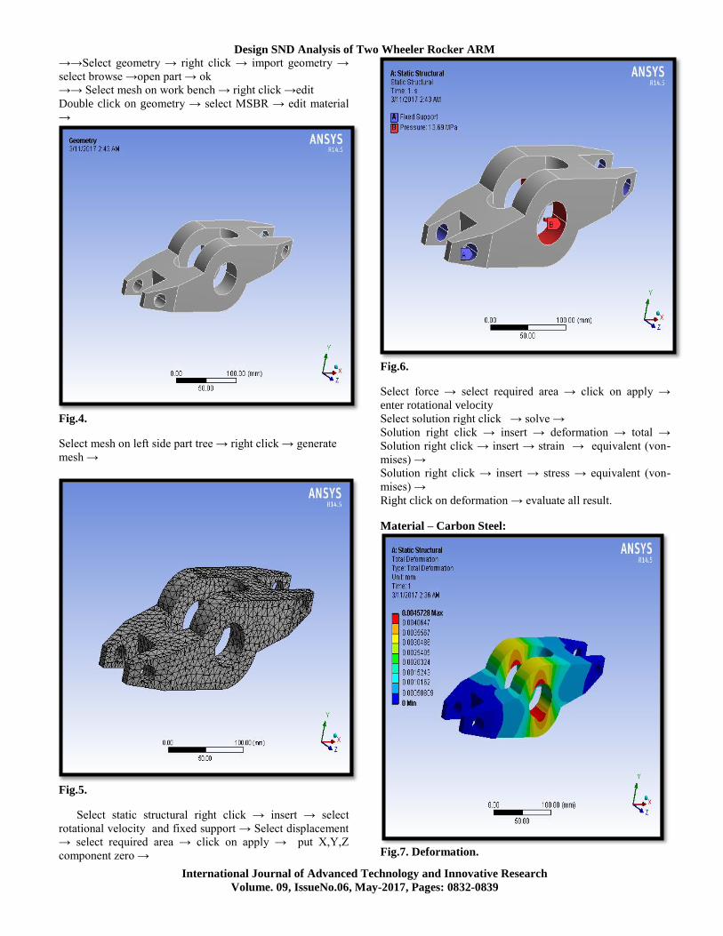
→→Select geometry → right click → import geometry →
select browse →open part → ok
→→ Select mesh on work bench → right click →edit
Double click on geometry → select MSBR → edit material
→
Fig.4.
Select mesh on left side part tree → right click → generate
mesh →
Fig.5.
Select static structural right click → insert → select
rotational velocity and fixed support → Select displacement
→ select required area → click on apply → put X,Y,Z
component zero →
Fig.6.
Select force → select required area → click on apply →
enter rotational velocity
Select solution right click → solve →
Solution right click → insert → deformation → total →
Solution right click → insert → strain → equivalent (von-
mises) →
Solution right click → insert → stress → equivalent (von-
mises) →
Right click on deformation → evaluate all result.
Material – Carbon Steel:
Fig.7. Deformation.

P. PRASAD
International Journal of Advanced Technology and Innovative Research
Volume. 09, IssueNo.06, May-2017, Pages: 0832-0839
Fig.8. Stress.
Fig.9. Strain.
Material – Aluminum Alloy 7075:
Fig.10. Deformation.
Fig.11. Stress.
Fig.12. Strain.
Material – HMCF UD:
Fig.13. Deformation.

Design SND Analysis of Two Wheeler Rocker ARM
International Journal of Advanced Technology and Innovative Research
Volume. 09, IssueNo.06, May-2017, Pages: 0832-0839
Fig.14. Stress.
Fig.15. Strain.
Fatigue Analysis Of Rocker Arm Material – Carbon
Steel:
Fig.16. Life.
Fig.17. Damage.
Fig.18. Safety factor.
Material – Aluminum Alloy 7075:
Fig.19. Life.

P. PRASAD
International Journal of Advanced Technology and Innovative Research
Volume. 09, IssueNo.06, May-2017, Pages: 0832-0839
Fig.20. Damage.
Fig.21. Safety factor.
Material – HMCF UD:
Fig.22. Life.
Fig.23. Damage.
Fig.24. Safety factor.
Modal Analysis Of Rocker ARM Material – Carbon
Steel:
Fig.25. Mode shape -1.

Design SND Analysis of Two Wheeler Rocker ARM
International Journal of Advanced Technology and Innovative Research
Volume. 09, IssueNo.06, May-2017, Pages: 0832-0839
Fig.26. Mode shape -2.
Fig.27. Mode shape -3.
Fig.28. Mode shape -4.
Fig.29. Mode shape -5.
IV. RESULTS AND DISCUSSIONS ANALYSIS
RESULT TABLE
A. Static Analysis Results
TABLE I: Static Analysis Results
TABLE II: Modal Analysis Results
TABLE III: Fatigue Analysis Results

P. PRASAD
International Journal of Advanced Technology and Innovative Research
Volume. 09, IssueNo.06, May-2017, Pages: 0832-0839
V. CONCLUSION
For this we are modeling the arm using CREO
parametric software and the stressed regions are found
out using ANSYS software. Here in this thesis we are
observing that by changing different materials(carbon
steel, HMCF UD & Aluminum alloy7075). By observing the
static analysis the stress values are less for the carbon steel
compare with aluminum alloy and HMCF UD. By observing
the fatigue analysis the safety factor more for carbon steel
material. So it can be concluded the carbon steel is better
material for rocker arm.
Future Scope: By using composite material the stress values
are reduced by that the life time of the rocker arm increases.
VI. REFERENCES [1]Chin-Sung Chung and Ho-Kyung Kim (2010), “Safety
Evaluation of the Rocker Arm of a Diesel Engine”, Materials
& Design, Vol. 31, No. 2, pp. 940-945.
[2]Christer Spiegelberg and Soren Andersson (2006),
“Simulation of Friction and Wear in the Contact Between the
Valve Bridge and Rocker Arm Pad in a Cam Mechanism”,
Machine Design, Royal Institute of Technology, S-100 44
Stockholm, Sweden.
[3]Dong-Woo Lee, Soo-Jin Lee, Seok-Swoo Cho and Won-
Sik Joo (2005), “Failure of Rocker Arm Shaft for 4-Cylinder
SOHC Engine”, Engineering Failure Analysis, Vol. 12, No.
3, pp. 405-412.
[4]Dong Woo Lee, Seok Swoo Cho and Won Sik Joo
(2008), “An Estimation of Failure Stress Condition in
Rocker Arm Shaft Through FEA and Microscopic
Fractography”.
[5]Giovanni Scire Mammano and Eugenio Dragoni (2013),
“Design and Testing of an Enhanced Shape Memory
Actuator Elastically Compensated by a Bistable Rocker
Arm”, Structures Journal of Intelligent Material Systems and
Structures.
[6]Hendriksma N, Kunz T and Greene C (2007), “Design
and Development of a 2-Step Rocker Arm”, SAE
International, USA.
[7]James M Miller (1980), “Rocker Arm Having
Perpendicular Geometry at Valve Mid Lift”, United States
Patent Appl. No. 211, 638, December 1.
[8]Kano M and Tanimoto I (1991), “Wear Resistance
Properties of Ceramic Rocker Arm Pads”, pp. 6-1, Materials.
Author Profile:
P.PRASAD Received his BTECH Degree
in Mechanical Engineering from Dr. Paul
Raj Engg College, Yatapaka, Khammam
(Dt), A.P and MTECH Degree in Thermal
Engineering From Andhra University,
Visakhapatnam, A.P. His is currently
working as Assistant Professor in Gonna
Institute of Information Technology and
sciences, Aganampudi, Visakhapatnam, A.P, India.