Capacity Assessment of a Transmission Tower Under Wind Loading
Accepted paper for the IEEE Power Engineering Society Winter Meeting, Columbus, Ohio, 2001
Abstract: Overloading of power transformers can become necessaryin open electricity markets due to economic reasons or simply toensure continuous energy supply. During an overload circle acceler-ated ageing and damages have to be strictly avoided. In order tocontrol overload cycles intelligent on-line monitoring systems areneeded. In this contribution the on-line calculation of the overloadcapacity and the integration in a monitoring system are described.By measurement of environmental and loading conditions it deliverscontinuously information on the maximum continuous and shorttime overload considering the actual preload of the transformeraccording to IEC 60354. The presentation of practical experiencesshows the considerable possibilities regarding optimization of trans-former operation during normal cyclic loading and emergency cases.Also a load dependent control of the cooling unit by the monitoringsystem allows to increase the overload capacity and optimize thehot-spot temperature.
Keywords: On-line Monitoring System, Power Transformer, Life-time Assessment, Thermal Model, Overload Calculation.
I. INTRODUCTION
With opening the current markets for generation and trans-mission of electrical energy the utilities are confronted withnew operating conditions. The high demands on generationand transmission combined with modified load cycles canlead to load flows not planned before. The utilization of apower station or a grid as high as possible, and therefore ofevery electrical equipment gets due to reasons of costs moreand more important. But due to the binded reliability of sup-ply and therefore costs in case of failures an endangering ofthe electrical equipment must be avoided under all circum-stances. On these reflections a controlled overloading of theelectrical equipment, as for example of power transformers,can be more economically advantageous than the extension ofthe network. Assuming from thermal limiting currents firmlydefined, basically there are two sorts of overloads [1]. Over-loads which are combined with a higher conductor tempera-ture than the rated value lead to an extremely acceleratedageing of the insulation and should therefore only be permit-ted in cases of emergency, like in order to prevent a systemcollapse. Operating conditions where load current flowsabove the thermal rated value, but where due to favorableambient conditions no higher conductor temperature than thepermitted temperature of ratings occurs, can be expected ofthe transformer. To avoid improper operating conditions an
exact supervision is necessary in both cases. Monitoring fa-cilities which can take on this task are available with modernmonitoring systems [2, 3].
A thermal model which should be integrated into the moni-toring system has to fulfil several criteria.
• The model should be almost independent of the trans-former, which means that only a few design-dependentvariables should have to be adapted. Because it has to beused for old transformers independent of manufacturer,these variables should be extractable out of the test pro-tocols of the transformer. This prevents the use of highsophisticated models [4, 5, 6].
• The model must be sufficiently accurate.
• The sensors which deliver the input values for the modelmust be possible to retrofit to transformers already in-stalled in the substation. This prevents for example theuse of fibre optics for direct measurement of hot-spottemperatures.
• The model must be commonly accepted. So the authorschoose a model based on the recommendations of theIEC 354 Loading guide for oil immersed power trans-formers [1].
II. OVERLOAD CALCULATION
A. Equivalent circuit of a one-body system
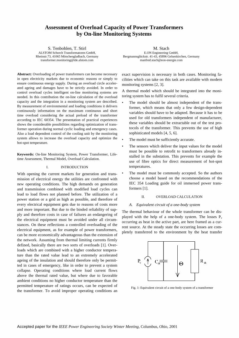
The thermal behaviour of the whole transformer can be dis-played with the help of a one-body system. The losses Pv
occurring as heat in the active part, are here framed as a cur-rent source. At the steady state the occurring losses are com-pletely transferred to the environment by the heat transfer
Assessment of Overload Capacity of Power Transformersby On-line Monitoring Systems
S. Tenbohlen, T. StirlALSTOM Schorch Transformatoren GmbH,
Rheinstr.73, 41065 Mönchengladbach, [email protected]
M. StachE.ON Engineering GmbH,
Bergmannsglückstr. 41-43, 45896 Gelsenkirchen, [email protected]
Fig. 1: Equivalent circuit of a one-body system of a transformer
Accepted paper for the IEEE Power Engineering Society Winter Meeting, Columbus, Ohio, 2001
2
resistance Rth. Are there any timely modified heat flows orfluctuations of the ambient temperature, additionally the heatcapacity Cth of the transformer must be taken into account.
The temperature drop at the parallel connection Cth and thethermal resistance Rth corresponds to the overtemperature Θof the oil in the transformer. The neutral of the circuit is at thepotential of the ambient temperature. For the step response ofthe temperature drop at the thermal resistance Rth is valid:
( )
−⋅⋅=Θ
−τt
thv eRPt 1 ; thth CR ⋅=τ . (1)
Materials of different numbers and with different specific heatcapacities are used in a transformer. Due to the whole trans-former is treated as one body in this equivalent network dia-gram, the heat capacity of the whole transformer must be builtout of the heat capacities and the masses of the single compo-nents:
OilOilFeFeCoCoth mcmcmcC ⋅+⋅+⋅≈ . (2)
The cooling power of the cooling unit is specified by themanufacturer for a certain working point. Based on this speci-fication the cooling power Pcool can be calculated for otherambient temperatures and oil temperatures. For the thermalresistance of the whole cooling plant with tank it is:
1
,_,_
,
−
⋅+
−= TankTank
ninAirninOil
ncoolth O
PR α
ϑϑ. (3)
By operating a transformer losses result in the heating of theactive part. The losses can be classified into load dependentand load independent losses. The no-load losses P0 have theirorigin in the transformer core. Their magnitude is influencedby various factors such as core design, quality of core platematerial, induction and mass of core. The load losses Pk aremade up of the copper losses and the stray losses in thewinding ends and certain transformer parts due to eddy cur-rents. Both loss components are proportional to the square ofthe load current flowing in the windings.
0
2
, PI
IPP
nnkV +
= . (4)
B. Methods of calculating the overload capacity
1) Normal cyclic loadingA higher ambient temperature or a higher than rated loadcurrent is applied during part of the cycle, but, from the pointof view of thermal ageing, this loading is equivalent to therated load at normal ambient temperature [1]. This continuousoverloading means that the overload duration is at least fivetimes longer than the thermal time constant of the transformerspecified by the heat capacity and the thermal resistance ofthe whole cooling plant. This time constant amounts to sev-eral hours at large transformers. Wanted is now the load cur-
rent the transformer can be loaded with, so that the hot-spottemperature ϑh amounts to 120 °C (OD cooling). The hot-spottemperature is composed of the ambient temperature ϑAir, thetop oil temperature rise and the winding gradient ΘCo_Oil
evaluated with hot-spot factor h.
The ambient temperature is available as a measuring value.Against that the top oil temperature rise (calculated acc. (1)and the winding gradient ΘCo_Oil are depending on the actualload current I of the transformer:
nOilCo
y
nth
nnkAirh I
IhRP
I
IP ,_0
2
, )( Θ⋅
⋅+⋅+
⋅+= ϑϑ . (5)
P0, Pk,n, Rth, ΘCu_Oil,n, winding exponent y and the hot-spotfactor h are given by the construction of the transformer orcan be investigated by the heat run test. The current I, withwhich the transformer can be permanently loaded by thegiven ambient temperature ϑAir, for OD-cooled transformerscan be calculated by solving the equation to I:
nOilCothnk
thAirhn hRP
RPII
,_,
0
Θ⋅+⋅⋅−−
⋅=ϑϑ
. (6)
For this kind of overload it is important to stress that cycleswith ageing rates greater than unity are compensated by cy-cles with ageing rate less than unity. It is to consider thatregarding the highest hot-spot temperature of 120 °C sug-gested by the IEC 60354 an ageing rate of 12 occurs, so that acontinuous supervision of the transformer and its ageing isnecessary in order to recognize intolerable operating condi-tions. Also the loading limits set by attached components likebushings and tap changers may not be lost out of sight.
2) Short-time emergency loadingThe short-time emergency loading is an unusual load for atransformer and is caused by the occurrence of more unlikelyevents which seriously disturb normal system loading, caus-ing the conductor hot-spots to reach dangerous levels [1]. Forthis overload operating of half an hour maximum a load factorup to 1.5 and a hot-spot temperature of 140 °C to 160 °Cmaximum can be tolerated at OD-cooled transformers. Forcalculation of emergency loading time the heat capacity of thedevice must be taken into account. From the total losses oc-curring by the required overload factor and from the thermalresistance of the cooling plant the stationary final value of thehot-spot temperature ϑh,∞ according (5) is calculated. Whenthe hot-spot temperature of 160 °C is exceeded, gas bubblesmay develop which could jeopardize the dielectric strength ofthe transformer. So an accurate modelling of the time con-stants of the transformer and its windings is necessary. Due tothe oil inside the windings changes more with the time con-stant of the winding (several minutes) than with the biggertime constant of the whole tank, here the time constant τh hasto be suited to (two-body system). So the hot-spot tempera-
Accepted paper for the IEEE Power Engineering Society Winter Meeting, Columbus, Ohio, 2001
3
ture is increasing from its actual value ϑh,∞ to the infinitevalue by:
( ) acth
t
acthhhhet ,,, 1)( ϑϑϑϑ τ +
−⋅−≈
−
∞ . (7)
An important precondition for the calculation of the overloadduration is the exactly fixing of the hot-spot temperature ϑh,act
of the transformer at the beginning of the overload. Thereforethe actual top oil temperature and the hot-spot temperature ispermanently calculated iteratively by the monitoring system.The time t up to the heating of the transformer to a hot-spottemperature of 140 °C results by solving (7):
−
−°−⋅−=
∞ akthh
akthh
Ct
,,
,1401ln
ϑϑ
ϑτ . (8)
III. INCORPORATION OF OVERLOAD PROGNOSISINTO THE MONITORING SYSTEM
To guarantee a reliable and economical electrical power sup-ply, a modern equipment monitoring, especially for the utili-zation at power transformers, would provide a solution. Dueto a continuous supervision with a monitoring system it ispossible to make exact statements about the operating condi-tion of the transformer and therefore as described by theoverload prognosis to optimize the operation.
Transformer outage rate statistics indicate on-load tap-changer, active part and bushings as the most frequent causeof long duration outages [7]. Therefore the installation of acomprehensive monitoring system to warn in case of an on-coming fault is advisable for strategically important powertransformers such as generator transformers. Due to an earlydetection of abnormal conditions it is further possible to avoidfaults and than to change over from a time-based to a condi-tion-based maintenance which can lead to a considerablereduction of maintenance expenditures. By knowing the oper-ating life and actual condition of the transformer a high andcontrolled exploitation of the residual service life can bereached. In case of demand the residual lifetime can be ex-tended by specific actions (Life-Management).
A. System description
Characteristics for the quality of a monitoring system are highmodularity and flexibility, because different types and waysof erection of transformers always make an adaptation of thesystem to the specific requirements necessary. Because of itsmodularity the Alstom monitoring system MS 2000 can eas-ily be focused on the requirements of the monitored trans-former and the customers needs. A multitude of differentmeasurable variables can be collected. However, to use theentire spectrum at one transformer is very costly and notalways useful. Therefore, sensor technology must be adjusted
to the specific requirements of a certain transformer, depend-ing on its age, condition and importance [2].
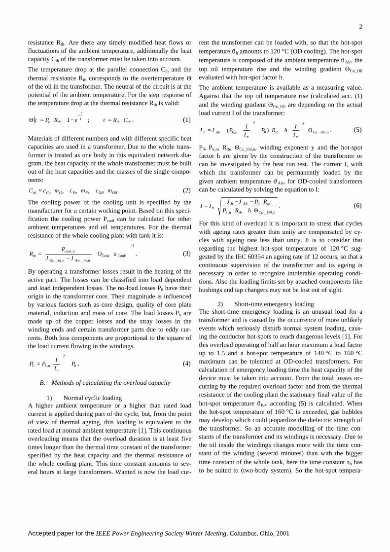
A high flexibility of the monitoring systems architecture canbe achieved by the use of field bus technology. Instead ofmany single wires only one bus cable has to be laid, on onehand the expenditures for wiring at the specific transformerare minimized. This is especially important for a fast and easyretrofitting of transformers which are currently in operation.On the other hand a supervision of a complete transformerbank with a monitoring system is realized by connection ofthe different decentralized monitoring modules dedicated tothe individual transformers by the field bus (Fig. 2). TheMS 2000 server erected centrally in a building of the substa-tion so enables the supervision of all transformers in thepower station, which means a reduction of expenditures forhard- and software. Comparing this with a solution where thePC is installed directly at the transformer the centralizedserver solution offers several additional advantages:
• The lifetime of the PC is not reduced by vibrations orheat of the transformer,
• the integration into the local area network for data visu-alization by an ethernet link is easier to achieve,
• only one telephone line is needed to have access to alltransformers.
The measuring data are recorded in the millisecond grid bymeans of the multi-tasking and real-time capable operatingsystem QNX. For the execution of the multiple tasks of thesoftware, such as event controlled data processing and stor-age, visualization and communication a flexible process con-trol system is used.
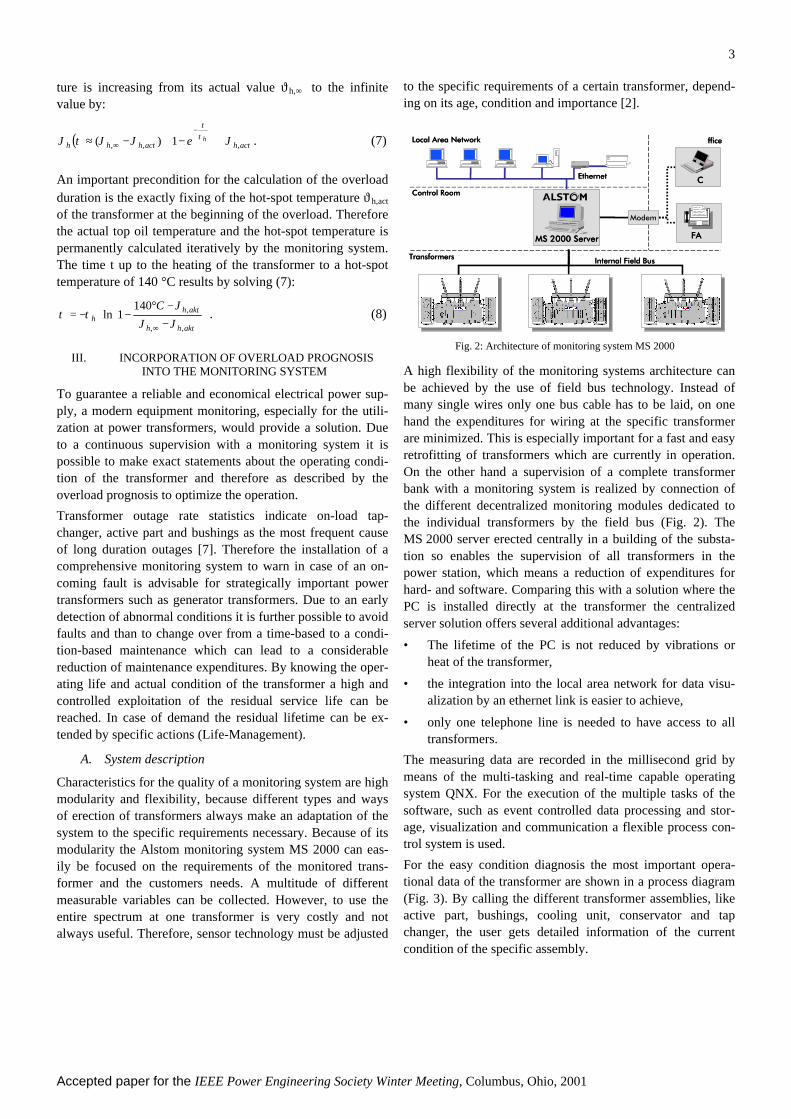
For the easy condition diagnosis the most important opera-tional data of the transformer are shown in a process diagram(Fig. 3). By calling the different transformer assemblies, likeactive part, bushings, cooling unit, conservator and tapchanger, the user gets detailed information of the currentcondition of the specific assembly.
Control RoomControl Room
TransformersTransformers
Local Area Local Area NetworkNetwork
EthernetEthernet
Internal FieldInternal Field Bus Bus
MS 2000 ServerMS 2000 Server
Modem
PCPC
OfficeOffice
FAXFAX
abcd
Fig. 2: Architecture of monitoring system MS 2000
Accepted paper for the IEEE Power Engineering Society Winter Meeting, Columbus, Ohio, 2001
4
Fig. 3: On-line data screen of monitored transformer
For the extension of the monitoring system of the describedoverload calculation and an intelligent control of the coolingplant, it is used a PLC module included in the software. Socomplex calculations and control processes can be imple-mented with a programming language standardized accordingto IEC 1131-3.
The monitoring system MS 2000 can also be used to controlthe fans of the cooling system in a smart manner dependingon load current and oil and ambient temperature. The thermalresistance of the cooling unit is adapted to the necessary valueto carry away current losses by single switching of fans. Thisintelligent switching has some advantages compared with theconventional controlling, where fans are switched in twosteps dependent on top oil temperature:
• reduction of the transformers breathing by a more con-stant oil temperature,
• optimizing the hot-spot temperature leads into a reduc-tion of life consumption (Life-Management),
• by precooling the oil the short-time overload can be in-creased,
• decreasing of sound emission by single operation of fans.
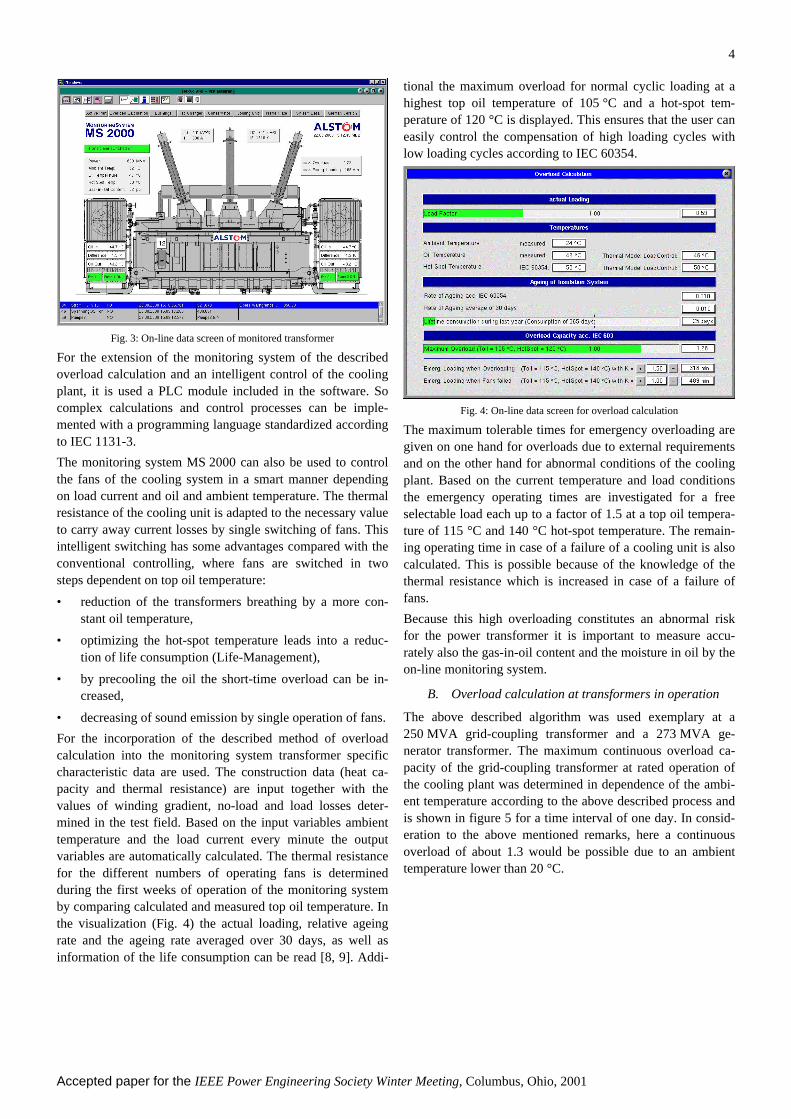
For the incorporation of the described method of overloadcalculation into the monitoring system transformer specificcharacteristic data are used. The construction data (heat ca-pacity and thermal resistance) are input together with thevalues of winding gradient, no-load and load losses deter-mined in the test field. Based on the input variables ambienttemperature and the load current every minute the outputvariables are automatically calculated. The thermal resistancefor the different numbers of operating fans is determinedduring the first weeks of operation of the monitoring systemby comparing calculated and measured top oil temperature. Inthe visualization (Fig. 4) the actual loading, relative ageingrate and the ageing rate averaged over 30 days, as well asinformation of the life consumption can be read [8, 9]. Addi-
tional the maximum overload for normal cyclic loading at ahighest top oil temperature of 105 °C and a hot-spot tem-perature of 120 °C is displayed. This ensures that the user caneasily control the compensation of high loading cycles withlow loading cycles according to IEC 60354.
Fig. 4: On-line data screen for overload calculation
The maximum tolerable times for emergency overloading aregiven on one hand for overloads due to external requirementsand on the other hand for abnormal conditions of the coolingplant. Based on the current temperature and load conditionsthe emergency operating times are investigated for a freeselectable load each up to a factor of 1.5 at a top oil tempera-ture of 115 °C and 140 °C hot-spot temperature. The remain-ing operating time in case of a failure of a cooling unit is alsocalculated. This is possible because of the knowledge of thethermal resistance which is increased in case of a failure offans.
Because this high overloading constitutes an abnormal riskfor the power transformer it is important to measure accu-rately also the gas-in-oil content and the moisture in oil by theon-line monitoring system.
B. Overload calculation at transformers in operation
The above described algorithm was used exemplary at a250 MVA grid-coupling transformer and a 273 MVA ge-nerator transformer. The maximum continuous overload ca-pacity of the grid-coupling transformer at rated operation ofthe cooling plant was determined in dependence of the ambi-ent temperature according to the above described process andis shown in figure 5 for a time interval of one day. In consid-eration to the above mentioned remarks, here a continuousoverload of about 1.3 would be possible due to an ambienttemperature lower than 20 °C.
Accepted paper for the IEEE Power Engineering Society Winter Meeting, Columbus, Ohio, 2001
5
00:00 04:00 08:00 12:00 16:00 20:00 24:0010
20
30
40
50
60
70
Top Oil Temp. calc. Oil Temp. HotSpot Temp. calc. HotSpot Temp. Ambient Temp.
Tem
pera
ture
(°C
)
Time (hours)
0,0
0,5
1,0
1,5
Load Factor Overload Factor
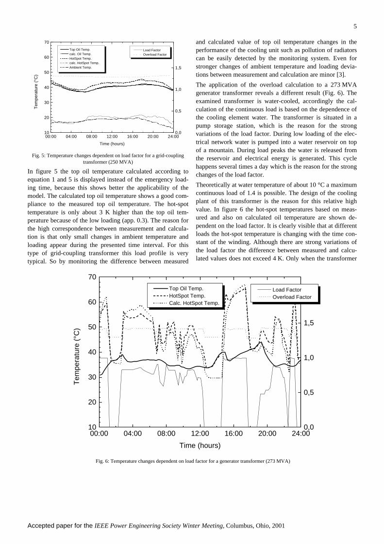
Fig. 5: Temperature changes dependent on load factor for a grid-couplingtransformer (250 MVA)
In figure 5 the top oil temperature calculated according toequation 1 and 5 is displayed instead of the emergency load-ing time, because this shows better the applicability of themodel. The calculated top oil temperature shows a good com-pliance to the measured top oil temperature. The hot-spottemperature is only about 3 K higher than the top oil tem-perature because of the low loading (app. 0.3). The reason forthe high correspondence between measurement and calcula-tion is that only small changes in ambient temperature andloading appear during the presented time interval. For thistype of grid-coupling transformer this load profile is verytypical. So by monitoring the difference between measured
and calculated value of top oil temperature changes in theperformance of the cooling unit such as pollution of radiatorscan be easily detected by the monitoring system. Even forstronger changes of ambient temperature and loading devia-tions between measurement and calculation are minor [3].
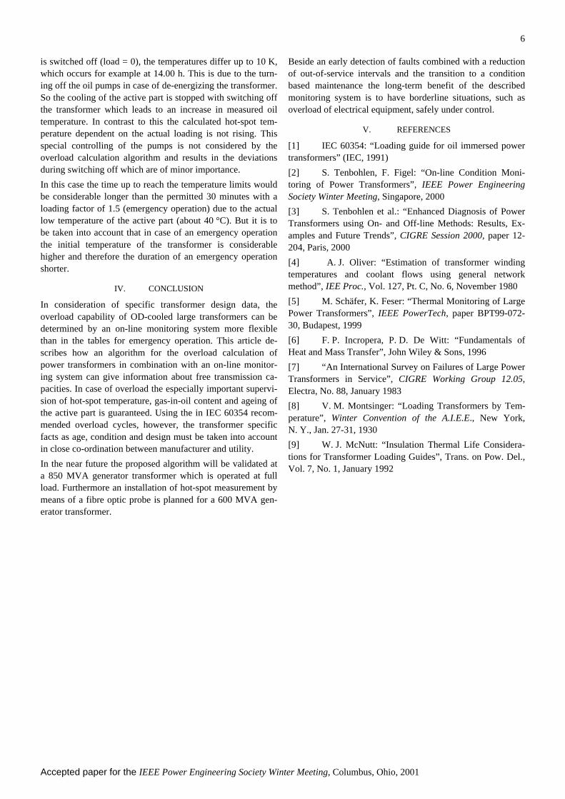
The application of the overload calculation to a 273 MVAgenerator transformer reveals a different result (Fig. 6). Theexamined transformer is water-cooled, accordingly the cal-culation of the continuous load is based on the dependence ofthe cooling element water. The transformer is situated in apump storage station, which is the reason for the strongvariations of the load factor. During low loading of the elec-trical network water is pumped into a water reservoir on topof a mountain. During load peaks the water is released fromthe reservoir and electrical energy is generated. This cyclehappens several times a day which is the reason for the strongchanges of the load factor.
Theoretically at water temperature of about 10 °C a maximumcontinuous load of 1.4 is possible. The design of the coolingplant of this transformer is the reason for this relative highvalue. In figure 6 the hot-spot temperatures based on meas-ured and also on calculated oil temperature are shown de-pendent on the load factor. It is clearly visible that at differentloads the hot-spot temperature is changing with the time con-stant of the winding. Although there are strong variations ofthe load factor the difference between measured and calcu-lated values does not exceed 4 K. Only when the transformer
00:00 04:00 08:00 12:00 16:00 20:00 24:0010
20
30
40
50
60
70
Top Oil Temp. HotSpot Temp. Calc. HotSpot Temp.
Tem
pera
ture
(°C
)
Time (hours)
0,0
0,5
1,0
1,5
Load Factor Overload Factor
Fig. 6: Temperature changes dependent on load factor for a generator transformer (273 MVA)
Accepted paper for the IEEE Power Engineering Society Winter Meeting, Columbus, Ohio, 2001
6
is switched off (load = 0), the temperatures differ up to 10 K,which occurs for example at 14.00 h. This is due to the turn-ing off the oil pumps in case of de-energizing the transformer.So the cooling of the active part is stopped with switching offthe transformer which leads to an increase in measured oiltemperature. In contrast to this the calculated hot-spot tem-perature dependent on the actual loading is not rising. Thisspecial controlling of the pumps is not considered by theoverload calculation algorithm and results in the deviationsduring switching off which are of minor importance.
In this case the time up to reach the temperature limits wouldbe considerable longer than the permitted 30 minutes with aloading factor of 1.5 (emergency operation) due to the actuallow temperature of the active part (about 40 °C). But it is tobe taken into account that in case of an emergency operationthe initial temperature of the transformer is considerablehigher and therefore the duration of an emergency operationshorter.
IV. CONCLUSION
In consideration of specific transformer design data, theoverload capability of OD-cooled large transformers can bedetermined by an on-line monitoring system more flexiblethan in the tables for emergency operation. This article de-scribes how an algorithm for the overload calculation ofpower transformers in combination with an on-line monitor-ing system can give information about free transmission ca-pacities. In case of overload the especially important supervi-sion of hot-spot temperature, gas-in-oil content and ageing ofthe active part is guaranteed. Using the in IEC 60354 recom-mended overload cycles, however, the transformer specificfacts as age, condition and design must be taken into accountin close co-ordination between manufacturer and utility.
In the near future the proposed algorithm will be validated ata 850 MVA generator transformer which is operated at fullload. Furthermore an installation of hot-spot measurement bymeans of a fibre optic probe is planned for a 600 MVA gen-erator transformer.
Beside an early detection of faults combined with a reductionof out-of-service intervals and the transition to a conditionbased maintenance the long-term benefit of the describedmonitoring system is to have borderline situations, such asoverload of electrical equipment, safely under control.
V. REFERENCES
[1] IEC 60354: “Loading guide for oil immersed powertransformers” (IEC, 1991)
[2] S. Tenbohlen, F. Figel: “On-line Condition Moni-toring of Power Transformers”, IEEE Power EngineeringSociety Winter Meeting, Singapore, 2000
[3] S. Tenbohlen et al.: “Enhanced Diagnosis of PowerTransformers using On- and Off-line Methods: Results, Ex-amples and Future Trends”, CIGRE Session 2000, paper 12-204, Paris, 2000
[4] A. J. Oliver: “Estimation of transformer windingtemperatures and coolant flows using general networkmethod”, IEE Proc., Vol. 127, Pt. C, No. 6, November 1980
[5] M. Schäfer, K. Feser: “Thermal Monitoring of LargePower Transformers”, IEEE PowerTech, paper BPT99-072-30, Budapest, 1999
[6] F. P. Incropera, P. D. De Witt: “Fundamentals ofHeat and Mass Transfer”, John Wiley & Sons, 1996
[7] “An International Survey on Failures of Large PowerTransformers in Service”, CIGRE Working Group 12.05,Electra, No. 88, January 1983
[8] V. M. Montsinger: “Loading Transformers by Tem-perature”, Winter Convention of the A.I.E.E., New York,N. Y., Jan. 27-31, 1930
[9] W. J. McNutt: “Insulation Thermal Life Considera-tions for Transformer Loading Guides”, Trans. on Pow. Del.,Vol. 7, No. 1, January 1992