Assessment Accuracy of Static Relative Positioning Using ...
10
International Journal of Scientific & Engineering Research, Volume 6, Issue 8, August-2015 683 ISSN 2229-5518 IJSER © 2015 http://www.ijser.org Assessment Accuracy of Static Relative Positioning Using Single Frequency GPS Receivers Mahmoud I. El-Mewafi 1 , Ashraf A. Beshr 2 , Ismail Zaher 3 Abstract - Global Positioning System (GPS) technology today plays a very major role, for surveyors and geodesists especially for engineering works, mapping, and several geodetic applications. Many surveying projects are preferring low cost and accurate positioning technology for various applications. GPS applications can be grouped into static and kinematic applications. Static applications of GPS can be used for various precise applications such as position fix, establishing the geodetic networks and monitoring the structural deformation; while kinematic applications of GPS can be used in mapping of natural and artifial features. GPS receivers can be categorized also into single and dual frequency receivers. Dual-frequency receivers are the most accurate receivers due to their capabilities for eliminating a major error component (the Ionospheric effect), but these receivers are very expensive and therefore not very attractive to many applications. The low cost of single-frequency receivers is attractive, but these receivers are affected more by ionospheric errors than dual frequency receivers. This paper investigates the accuracy of static relative positioning using single frequency GPS receivers throughout comparing the baselines distances, Cartesian coordinates X, Y, and Z and loop closure in geodetic networks with different baseline lengths for the two cases; using single frequency and dual frequency GPS data by static techniques. The results show that, the difference in resulted loop closure using dual and single frequency is very small (within 5 mm) for baseline length up to 35 km. The difference in Cartesian coordinates from single and dual frequency data has a mean value of 19.19 mm with 5.75 mm standard deviation for 3D positioning discrepancy. These findings are satisfying the standard and specification of establishing the first-order geodetic networks, according to the Federal Geodetic Control Committee FGCC. Furthermore, It can be concluded that GPS single frequency receivers, which are less expensive than dual frequency receivers, can be used in establishing GPS control geodetic networks with baselines lengths up to 35 km. Keywords: DGPS, Single frequency receiver, Dual frequency data, accuracy, GIM from IGS. 1. Introduction GPS is mainly used to get 3D position of various features on the Earth, at the sea, and in the air. The positioning is determined by complicated signal transmitted from each GPS satellite antenna and receiving the signal by the antenna of various GPS receivers. Establishment of permanent GPS stations and GPS networks observations as references for other surveying applications must be performed with high accuracy [1]. Although GPS is the most accurate global navigation system yet developed, it faces significant errors and biases. The accuracy derived by GPS is governed by various factors. Factors, causing these errors, could be attributed to the satellites including satellite clock errors and orbital errors, to the propagation of the signal due to the atmospheric effects (ionosphere and troposphere) and multipath, to the receiver/antenna configuration, such as receiver clock bias, and antenna Phase center, to the station (coordinates, polar motion, earth body tides, ocean tide loading),and to the geometric locations of the GPS satellites as seen by the receiver (geometric effects). Biases in GPS are greatly eliminated either by modeling or by using special observing techniques, based on the concept of differenced modes [2]. GPS receivers are generally classified into single- frequency (LI) GPS receivers and dual-frequency (LI and L2) GPS receivers. The classification depends on the tracking capabilities of the GPS receiver. Dual-frequency receivers are the most accurate receivers due to their capabilities for eliminating a major error component (the ionospheric effect) by forming a linear combination using both frequencies (LI and L2) to form the ionosphere free linear combination (L3) observable. Dual-frequency receivers can deliver millimeter accuracy if proper procedures are followed, but these receivers are very expensive and therefore not very attractive to many professionals. The low cost of single-frequency receivers is attractive, but these receivers are not suitable for applications demanding high accuracies. This paper investigates the possibility of using single- frequency GPS receivers in static modes over different baselines lengths (up to 58 km) for various applications. To improve the accuracy of the single-frequency systems, DGPS are used for data collection and precise products such as precise orbits and ionospheric correction maps from IGS are used during processing of GPS baselines. The IJSER
Transcript of Assessment Accuracy of Static Relative Positioning Using ...
International Journal of Scientific & Engineering Research, Volume 6, Issue 8, August-2015 683 ISSN 2229-5518
IJSER © 2015 http://www.ijser.org
Assessment Accuracy of Static Relative
Positioning Using Single Frequency GPS Receivers
Mahmoud I. El-Mewafi1, Ashraf A. Beshr2 , Ismail Zaher3
Abstract - Global Positioning System (GPS) technology today plays a very major role, for surveyors and geodesists especially for engineering works, mapping, and several geodetic applications. Many surveying projects are preferring low cost and accurate positioning technology for various applications. GPS applications can be grouped into static and kinematic applications. Static applications of GPS can be used for various precise applications such as position fix, establishing the geodetic networks and monitoring the structural deformation; while kinematic applications of GPS can be used in mapping of natural and artifial features. GPS receivers can be categorized also into single and dual frequency receivers. Dual-frequency receivers are the most accurate receivers due to their capabilities for eliminating a major error component (the Ionospheric effect), but these receivers are very expensive and therefore not very attractive to many applications. The low cost of single-frequency receivers is attractive, but these receivers are affected more by ionospheric errors than dual frequency receivers.
This paper investigates the accuracy of static relative positioning using single frequency GPS receivers throughout comparing the baselines distances, Cartesian coordinates X, Y, and Z and loop closure in geodetic networks with different baseline lengths for the two cases; using single frequency and dual frequency GPS data by static techniques. The results show that, the difference in resulted loop closure using dual and single frequency is very small (within 5 mm) for baseline length up to 35 km. The difference in Cartesian coordinates from single and dual frequency data has a mean value of 19.19 mm with 5.75 mm standard deviation for 3D positioning discrepancy. These findings are satisfying the standard and specification of establishing the first-order geodetic networks, according to the Federal Geodetic Control Committee FGCC. Furthermore, It can be concluded that GPS single frequency receivers, which are less expensive than dual frequency receivers, can be used in establishing GPS control geodetic networks with baselines lengths up to 35 km.
Keywords: DGPS, Single frequency receiver, Dual frequency data, accuracy, GIM from IGS.
1. Introduction GPS is mainly used to get 3D position of various features
on the Earth, at the sea, and in the air. The positioning is determined by complicated signal transmitted from each GPS satellite antenna and receiving the signal by the antenna of various GPS receivers.
Establishment of permanent GPS stations and GPS
networks observations as references for other surveying applications must be performed with high accuracy [1]. Although GPS is the most accurate global navigation system yet developed, it faces significant errors and biases. The accuracy derived by GPS is governed by various factors. Factors, causing these errors, could be attributed to the satellites including satellite clock errors and orbital errors, to the propagation of the signal due to the atmospheric effects (ionosphere and troposphere) and multipath, to the receiver/antenna configuration, such as receiver clock bias, and antenna Phase center, to the station (coordinates, polar motion, earth body tides, ocean tide loading),and to the geometric locations of the GPS satellites as seen by the receiver (geometric effects). Biases in GPS are greatly eliminated either by modeling or by using special observing techniques, based on the concept of differenced
modes [2]. GPS receivers are generally classified into single-
frequency (LI) GPS receivers and dual-frequency (LI and L2) GPS receivers. The classification depends on the tracking capabilities of the GPS receiver. Dual-frequency receivers are the most accurate receivers due to their capabilities for eliminating a major error component (the ionospheric effect) by forming a linear combination using both frequencies (LI and L2) to form the ionosphere free linear combination (L3) observable. Dual-frequency receivers can deliver millimeter accuracy if proper procedures are followed, but these receivers are very expensive and therefore not very attractive to many professionals. The low cost of single-frequency receivers is attractive, but these receivers are not suitable for applications demanding high accuracies.
This paper investigates the possibility of using single-frequency GPS receivers in static modes over different baselines lengths (up to 58 km) for various applications. To improve the accuracy of the single-frequency systems, DGPS are used for data collection and precise products such as precise orbits and ionospheric correction maps from IGS are used during processing of GPS baselines. The
IJSER
International Journal of Scientific & Engineering Research, Volume 6, Issue 8, August-2015 684 ISSN 2229-5518
IJSER © 2015 http://www.ijser.org
methodology of investigation and the description of the field test is also presented. Finally, the analysis of the obtained results and graphs supported with the statistical analysis will be shown, from which the important conclusions and recommendations will be drawn.
2. DGPS and Static GPS observation technique. Surveying works with GPS have conventionally been
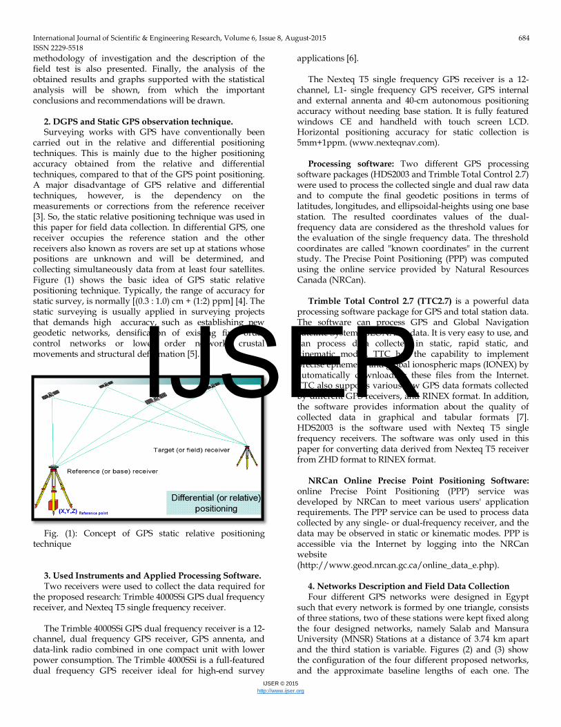
carried out in the relative and differential positioning techniques. This is mainly due to the higher positioning accuracy obtained from the relative and differential techniques, compared to that of the GPS point positioning. A major disadvantage of GPS relative and differential techniques, however, is the dependency on the measurements or corrections from the reference receiver [3]. So, the static relative positioning technique was used in this paper for field data collection. In differential GPS, one receiver occupies the reference station and the other receivers also known as rovers are set up at stations whose positions are unknown and will be determined, and collecting simultaneously data from at least four satellites. Figure (1) shows the basic idea of GPS static relative positioning technique. Typically, the range of accuracy for static survey, is normally [(0.3 : 1.0) cm + (1:2) ppm] [4]. The static surveying is usually applied in surveying projects that demands high accuracy, such as establishing new geodetic networks, densification of existing first order control networks or lower order network, crustal movements and structural deformation [5].
Fig. (1): Concept of GPS static relative positioning
technique 3. Used Instruments and Applied Processing Software. Two receivers were used to collect the data required for
the proposed research: Trimble 4000SSi GPS dual frequency receiver, and Nexteq T5 single frequency receiver.
The Trimble 4000SSi GPS dual frequency receiver is a 12-
channel, dual frequency GPS receiver, GPS annenta, and data-link radio combined in one compact unit with lower power consumption. The Trimble 4000SSi is a full-featured dual frequency GPS receiver ideal for high-end survey
applications [6]. The Nexteq T5 single frequency GPS receiver is a 12-
channel, L1- single frequency GPS receiver, GPS internal and external annenta and 40-cm autonomous positioning accuracy without needing base station. It is fully featured windows CE and handheld with touch screen LCD. Horizontal positioning accuracy for static collection is 5mm+1ppm. (www.nexteqnav.com).
Processing software: Two different GPS processing
software packages (HDS2003 and Trimble Total Control 2.7) were used to process the collected single and dual raw data and to compute the final geodetic positions in terms of latitudes, longitudes, and ellipsoidal-heights using one base station. The resulted coordinates values of the dual-frequency data are considered as the threshold values for the evaluation of the single frequency data. The threshold coordinates are called "known coordinates" in the current study. The Precise Point Positioning (PPP) was computed using the online service provided by Natural Resources Canada (NRCan).
Trimble Total Control 2.7 (TTC2.7) is a powerful data
processing software package for GPS and total station data. The software can process GPS and Global Navigation Satellite System (GLONASS) data. It is very easy to use, and can process data collected in static, rapid static, and kinematic modes. TTC has the capability to implement precise ephemeris and global ionospheric maps (IONEX) by automatically downloading these files from the Internet. TTC also supports various raw GPS data formats collected by different GPS receivers, and RINEX format. In addition, the software provides information about the quality of collected data in graphical and tabular formats [7]. HDS2003 is the software used with Nexteq T5 single frequency receivers. The software was only used in this paper for converting data derived from Nexteq T5 receiver from ZHD format to RINEX format.
NRCan Online Precise Point Positioning Software:
online Precise Point Positioning (PPP) service was developed by NRCan to meet various users' application requirements. The PPP service can be used to process data collected by any single- or dual-frequency receiver, and the data may be observed in static or kinematic modes. PPP is accessible via the Internet by logging into the NRCan website (http://www.geod.nrcan.gc.ca/online_data_e.php).
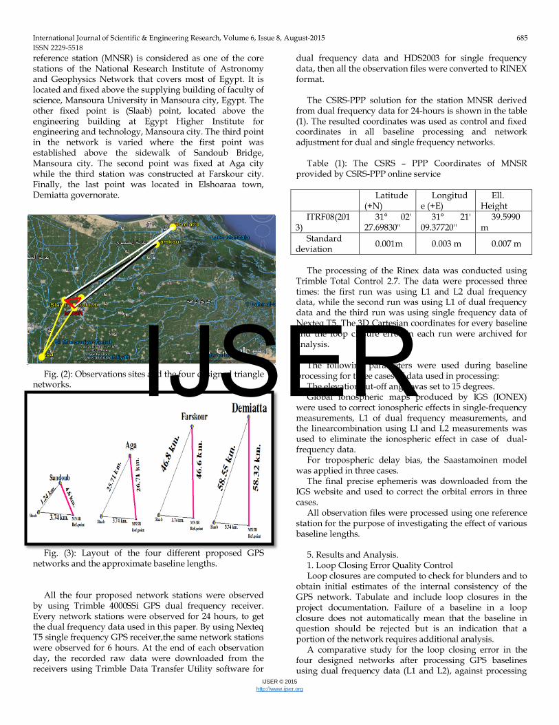
4. Networks Description and Field Data Collection Four different GPS networks were designed in Egypt
such that every network is formed by one triangle, consists of three stations, two of these stations were kept fixed along the four designed networks, namely Salab and Mansura University (MNSR) Stations at a distance of 3.74 km apart and the third station is variable. Figures (2) and (3) show the configuration of the four different proposed networks, and the approximate baseline lengths of each one. The
IJSER
International Journal of Scientific & Engineering Research, Volume 6, Issue 8, August-2015 685 ISSN 2229-5518
IJSER © 2015 http://www.ijser.org
reference station (MNSR) is considered as one of the core stations of the National Research Institute of Astronomy and Geophysics Network that covers most of Egypt. It is located and fixed above the supplying building of faculty of science, Mansoura University in Mansoura city, Egypt. The other fixed point is (Slaab) point, located above the engineering building at Egypt Higher Institute for engineering and technology, Mansoura city. The third point in the network is varied where the first point was established above the sidewalk of Sandoub Bridge, Mansoura city. The second point was fixed at Aga city while the third station was constructed at Farskour city. Finally, the last point was located in Elshoaraa town, Demiatta governorate.
Fig. (2): Observations sites and the four designed triangle
networks. Fig. (3): Layout of the four different proposed GPS
networks and the approximate baseline lengths. All the four proposed network stations were observed
by using Trimble 4000SSi GPS dual frequency receiver. Every network stations were observed for 24 hours, to get the dual frequency data used in this paper. By using Nexteq T5 single frequency GPS receiver,the same network stations were observed for 6 hours. At the end of each observation day, the recorded raw data were downloaded from the receivers using Trimble Data Transfer Utility software for
dual frequency data and HDS2003 for single frequency data, then all the observation files were converted to RINEX format.
The CSRS-PPP solution for the station MNSR derived
from dual frequency data for 24-hours is shown in the table (1). The resulted coordinates was used as control and fixed coordinates in all baseline processing and network adjustment for dual and single frequency networks.
Table (1): The CSRS – PPP Coordinates of MNSR
provided by CSRS-PPP online service
Ell. Height
Longitude (+E)
Latitude (+N)
39.5990m
31° 21' 09.37720''
31° 02' 27.69830''
ITRF08(2013)
0.007 m 0.003 m 0.001m Standard deviation
The processing of the Rinex data was conducted using
Trimble Total Control 2.7. The data were processed three times: the first run was using L1 and L2 dual frequency data, while the second run was using L1 of dual frequency data and the third run was using single frequency data of Nexteq T5. The 3D Cartesian coordinates for every baseline and the loop closure error in each run were archived for analysis.
The following parameters were used during baseline
processing for three cases of data used in processing: The elevation cut-off angle was set to 15 degrees. Global ionospheric maps produced by IGS (IONEX)
were used to correct ionospheric effects in single-frequency measurements, L1 of dual frequency measurements, and the linearcombination using LI and L2 measurements was used to eliminate the ionospheric effect in case of dual-frequency data.
For tropospheric delay bias, the Saastamoinen model was applied in three cases.
The final precise ephemeris was downloaded from the IGS website and used to correct the orbital errors in three cases.
All observation files were processed using one reference station for the purpose of investigating the effect of various baseline lengths.
5. Results and Analysis. 1. Loop Closing Error Quality Control Loop closures are computed to check for blunders and to
obtain initial estimates of the internal consistency of the GPS network. Tabulate and include loop closures in the project documentation. Failure of a baseline in a loop closure does not automatically mean that the baseline in question should be rejected but is an indication that a portion of the network requires additional analysis.
A comparative study for the loop closing error in the four designed networks after processing GPS baselines using dual frequency data (L1 and L2), against processing
IJSER
International Journal of Scientific & Engineering Research, Volume 6, Issue 8, August-2015 686 ISSN 2229-5518
IJSER © 2015 http://www.ijser.org
the same baselines using L1 of dual frequency data and against processing the same baselines using Nexteq T5 single frequency data was done.
Loop closing error (δ) can be calculated for any network as following (for example MNSR- Slaab - Sandoub Network):
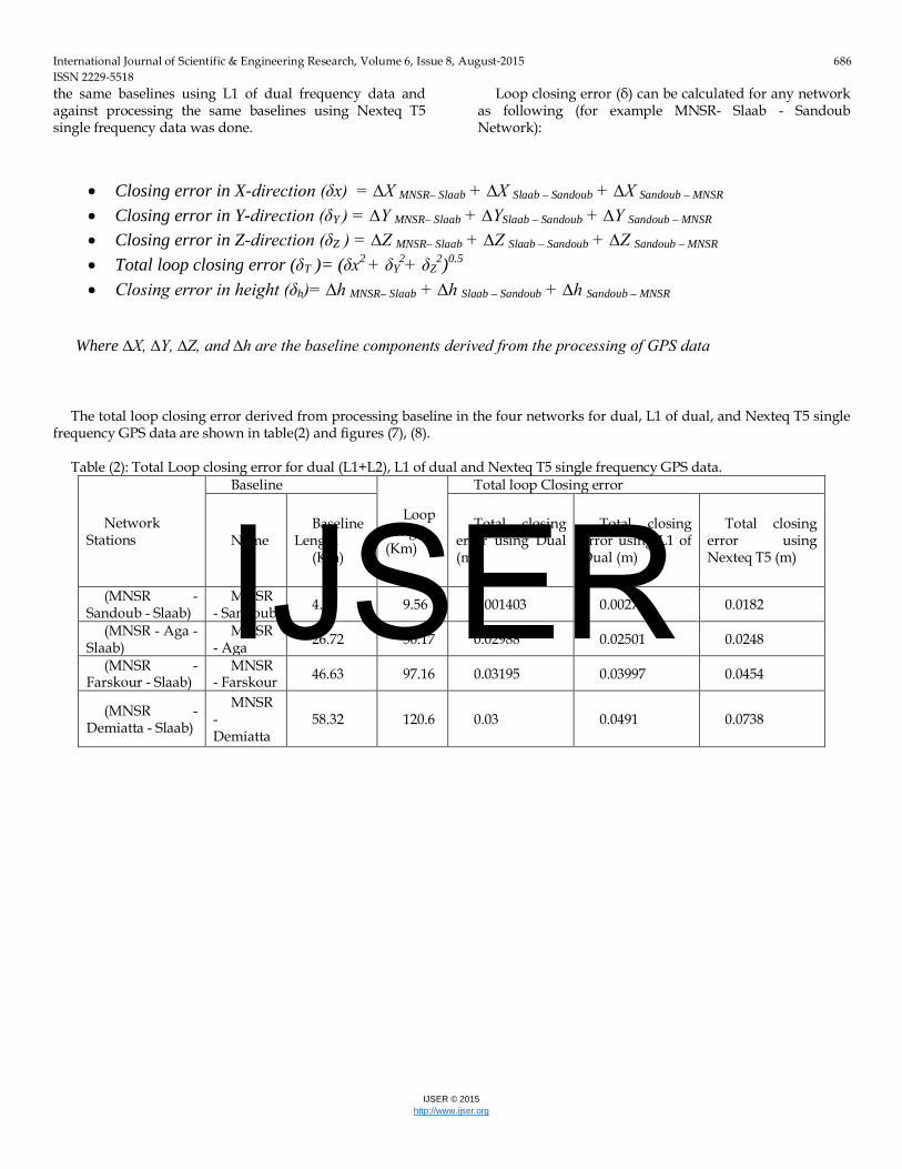
The total loop closing error derived from processing baseline in the four networks for dual, L1 of dual, and Nexteq T5 single
frequency GPS data are shown in table(2) and figures (7), (8). Table (2): Total Loop closing error for dual (L1+L2), L1 of dual and Nexteq T5 single frequency GPS data.
Network Stations
Baseline
Loop Length (Km)
Total loop Closing error
Name Baseline
Length (Km)
Total closing error using Dual (m)
Total closing error using L1 of Dual (m)
Total closing error using Nexteq T5 (m)
(MNSR - Sandoub - Slaab)
MNSR - Sandoub 4.59 9.56 0.001403 0.00271 0.0182
(MNSR - Aga - Slaab)
MNSR - Aga 26.72 56.17 0.02988 0.02501 0.0248
(MNSR - Farskour - Slaab)
MNSR - Farskour 46.63 97.16 0.03195 0.03997 0.0454
(MNSR - Demiatta - Slaab)
MNSR - Demiatta
58.32 120.6 0.03 0.0491 0.0738
• Closing error in X-direction (δx) = ∆X MNSR– Slaab + ∆X Slaab – Sandoub + ∆X Sandoub – MNSR • Closing error in Y-direction (δY ) = ∆Y MNSR– Slaab + ∆YSlaab – Sandoub + ∆Y Sandoub – MNSR • Closing error in Z-direction (δZ ) = ∆Z MNSR– Slaab + ∆Z Slaab – Sandoub + ∆Z Sandoub – MNSR • Total loop closing error (δT )= (δx2 + δY
2+ δZ2)0.5
• Closing error in height (δh)= ∆h MNSR– Slaab + ∆h Slaab – Sandoub + ∆h Sandoub – MNSR
Where ∆X, ∆Y, ∆Z, and ∆h are the baseline components derived from the processing of GPS data
IJSER
International Journal of Scientific & Engineering Research, Volume 6, Issue 8, August-2015 687 ISSN 2229-5518
IJSER © 2015 http://www.ijser.org
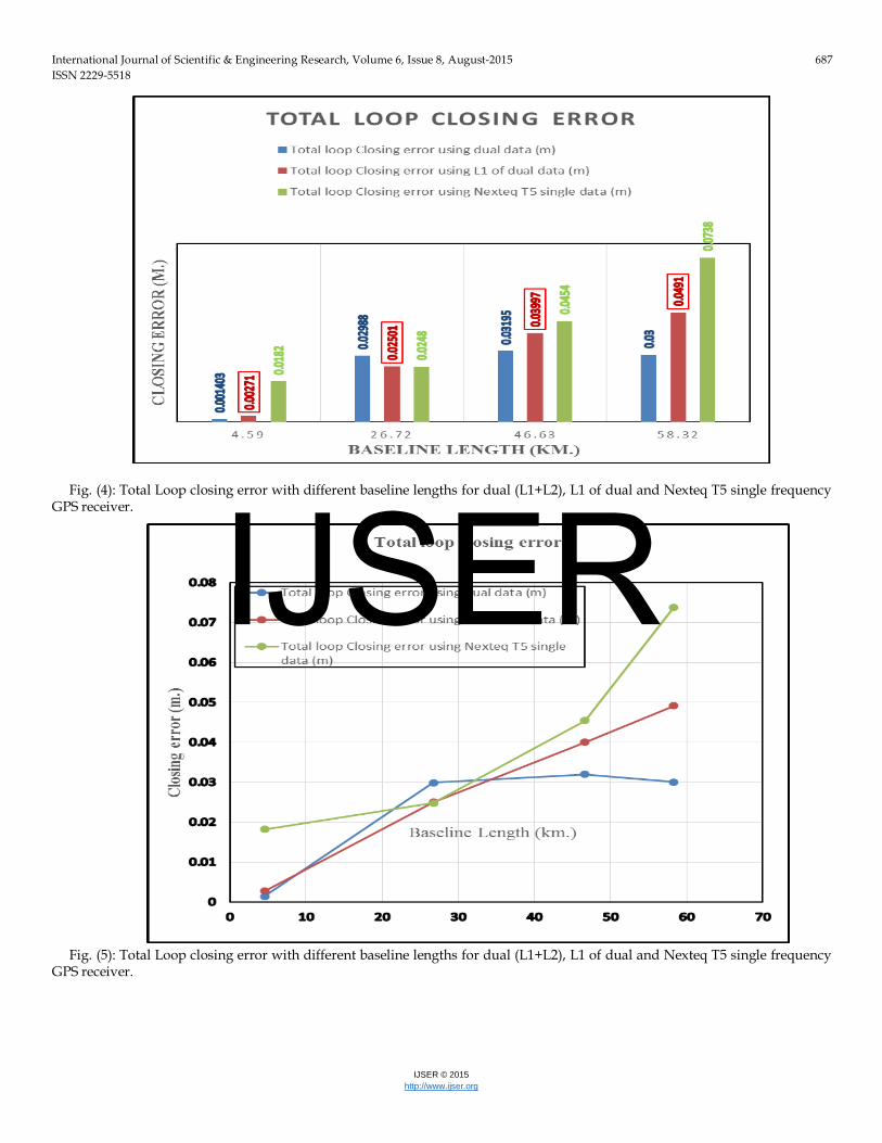
Fig. (4): Total Loop closing error with different baseline lengths for dual (L1+L2), L1 of dual and Nexteq T5 single frequency
GPS receiver. Fig. (5): Total Loop closing error with different baseline lengths for dual (L1+L2), L1 of dual and Nexteq T5 single frequency
GPS receiver.
IJSER
International Journal of Scientific & Engineering Research, Volume 6, Issue 8, August-2015 688 ISSN 2229-5518
IJSER © 2015 http://www.ijser.org
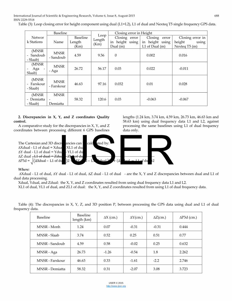
Table (3): Loop closing error for height component using dual (L1+L2), L1 of dual and Nexteq T5 single frequency GPS data.
Network Stations
Baseline Loop Length (Km)
Closing error in Height
Name Baseline
Length (Km)
Closing error in height using Dual (m)
Closing error in height using L1 of Dual (m)
Closing error in height using Nexteq T5 (m)
(MNSR - Sandoub - Slaab)
MNSR - Sandoub 4.59 9.56 0 0.002 0.016
(MNSR - Aga - Slaab)
MNSR - Aga 26.72 56.17 0.03 0.022 -0.011
(MNSR - Farskour - Slaab)
MNSR - Farskour 46.63 97.16 0.032 0.01 0.028
(MNSR - Demiatta - Slaab)
MNSR - Demiatta
58.32 120.6 0.03 -0.063 -0.067
2. Discrepancies in X, Y, and Z coordinates Quality
control. A comparative study for the discrepancies in X, Y, and Z
coordinates between processing different 6 GPS baselines
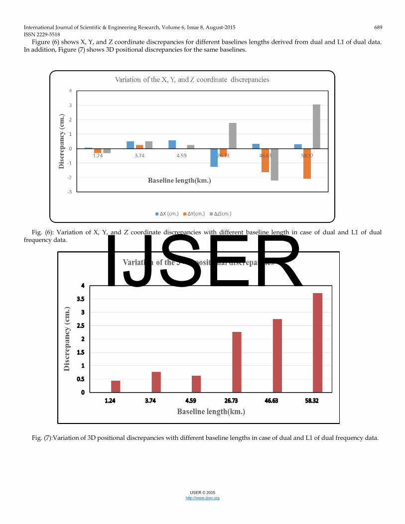
lengths (1.24 km, 3.74 km, 4.59 km, 26.73 km, 46.63 km and 58.63 km) using dual frequency data L1 and L2, against processing the same baselines using L1 of dual frequency data only.
The Cartesian and 3D discrepancies can be calculated by: ∆Xdual - L1 of dual = Xdual – XL1 of dual ∆Y dual - L1 of dual = Ydual – YL1 of dual ∆Z dual - L1 of dual = Zdual – ZL1 of dual ∆P3d = ��∆Xdual – L1 of dual �2 + �∆Y dual – L1 of dual �2 + (∆Z dual − L1 of dual)2 Where: ∆Xdual - L1 of dual, ∆Y dual - L1 of dual, ∆Z dual - L1 of dual - are the X, Y and Z discrepancies between dual and L1 of
dual data processing. Xdual, Ydual, and Zdual: the X, Y, and Z coordinates resulted from using dual frequency data L1 and L2. XL1 of dual, YL1 of dual, and ZL1 of dual: the X, Y, and Z coordinates resulted from using L1 of dual frequency data. Table (4): The discrepancies in X, Y, Z, and 3D position P, between processing the GPS data using dual and L1 of dual
frequency data.
Baseline Baseline length (km) ∆X (cm.) ∆Y(cm.) ∆Z(cm.) ∆P3d (cm.)
MNSR - Monh 1.24 0.07 -0.31 -0.31 0.444
MNSR - Slaab 3.74 0.52 0.25 0.51 0.77
MNSR - Sandoub 4.59 0.58 -0.02 0.25 0.632
MNSR - Aga 26.73 -1.26 -0.54 1.8 2.262
MNSR - Farskour 46.63 0.33 -1.61 -2.2 2.746
MNSR - Demiatta 58.32 0.31 -2.07 3.08 3.723
IJSER
International Journal of Scientific & Engineering Research, Volume 6, Issue 8, August-2015 689 ISSN 2229-5518
IJSER © 2015 http://www.ijser.org
Figure (6) shows X, Y, and Z coordinate discrepancies for different baselines lengths derived from dual and L1 of dual data. In addition, Figure (7) shows 3D positional discrepancies for the same baselines.
Fig. (6): Variation of X, Y, and Z coordinate discrepancies with different baseline length in case of dual and L1 of dual
frequency data. Fig. (7):Variation of 3D positional discrepancies with different baseline lengths in case of dual and L1 of dual frequency data.
IJSER
International Journal of Scientific & Engineering Research, Volume 6, Issue 8, August-2015 690 ISSN 2229-5518
IJSER © 2015 http://www.ijser.org
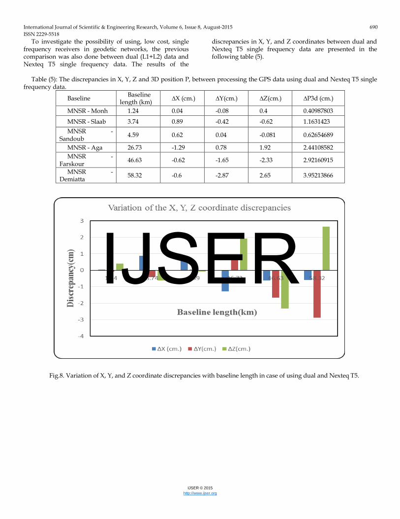
To investigate the possibility of using, low cost, single frequency receivers in geodetic networks, the previous comparison was also done between dual (L1+L2) data and Nexteq T5 single frequency data. The results of the
discrepancies in X, Y, and Z coordinates between dual and Nexteq T5 single frequency data are presented in the following table (5).
Table (5): The discrepancies in X, Y, Z and 3D position P, between processing the GPS data using dual and Nexteq T5 single
frequency data.
Baseline Baseline length (km) ∆X (cm.) ∆Y(cm.) ∆Z(cm.) ∆P3d (cm.)
MNSR - Monh 1.24 0.04 -0.08 0.4 0.40987803
MNSR - Slaab 3.74 0.89 -0.42 -0.62 1.1631423 MNSR -
Sandoub 4.59 0.62 0.04 -0.081 0.62654689
MNSR - Aga 26.73 -1.29 0.78 1.92 2.44108582 MNSR -
Farskour 46.63 -0.62 -1.65 -2.33 2.92160915
MNSR - Demiatta 58.32 -0.6 -2.87 2.65 3.95213866
Fig.8. Variation of X, Y, and Z coordinate discrepancies with baseline length in case of using dual and Nexteq T5.
IJSER
International Journal of Scientific & Engineering Research, Volume 6, Issue 8, August-2015 691 ISSN 2229-5518
IJSER © 2015 http://www.ijser.org
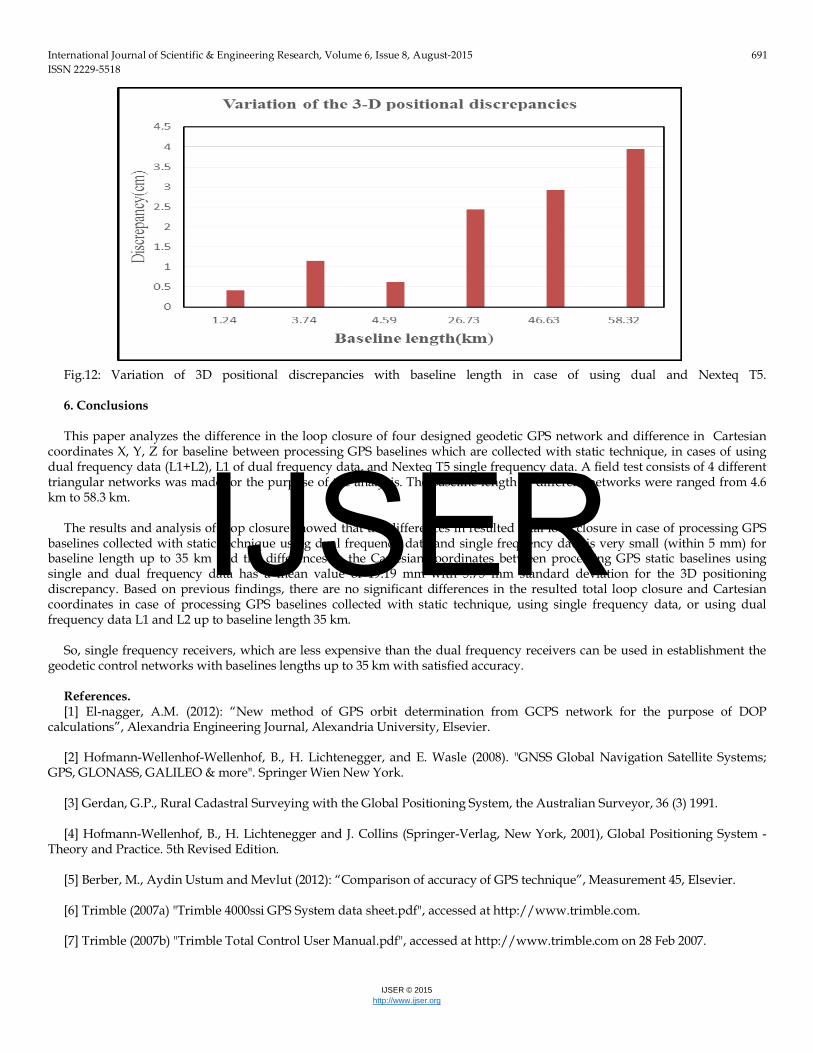
Fig.12: Variation of 3D positional discrepancies with baseline length in case of using dual and Nexteq T5. 6. Conclusions This paper analyzes the difference in the loop closure of four designed geodetic GPS network and difference in Cartesian
coordinates X, Y, Z for baseline between processing GPS baselines which are collected with static technique, in cases of using dual frequency data (L1+L2), L1 of dual frequency data, and Nexteq T5 single frequency data. A field test consists of 4 different triangular networks was made for the purpose of the analysis. The baseline length in different networks were ranged from 4.6 km to 58.3 km.
The results and analysis of loop closure showed that the differences in resulted total loop closure in case of processing GPS
baselines collected with static technique using dual frequency data and single frequency data is very small (within 5 mm) for baseline length up to 35 km and the differences in the Cartesian coordinates between processing GPS static baselines using single and dual frequency data has a mean value of 19.19 mm with 5.75 mm standard deviation for the 3D positioning discrepancy. Based on previous findings, there are no significant differences in the resulted total loop closure and Cartesian coordinates in case of processing GPS baselines collected with static technique, using single frequency data, or using dual frequency data L1 and L2 up to baseline length 35 km.
So, single frequency receivers, which are less expensive than the dual frequency receivers can be used in establishment the
geodetic control networks with baselines lengths up to 35 km with satisfied accuracy. References. [1] El-nagger, A.M. (2012): “New method of GPS orbit determination from GCPS network for the purpose of DOP
calculations”, Alexandria Engineering Journal, Alexandria University, Elsevier. [2] Hofmann-Wellenhof-Wellenhof, B., H. Lichtenegger, and E. Wasle (2008). "GNSS Global Navigation Satellite Systems;
GPS, GLONASS, GALILEO & more". Springer Wien New York. [3] Gerdan, G.P., Rural Cadastral Surveying with the Global Positioning System, the Australian Surveyor, 36 (3) 1991. [4] Hofmann-Wellenhof, B., H. Lichtenegger and J. Collins (Springer-Verlag, New York, 2001), Global Positioning System -
Theory and Practice. 5th Revised Edition. [5] Berber, M., Aydin Ustum and Mevlut (2012): “Comparison of accuracy of GPS technique”, Measurement 45, Elsevier. [6] Trimble (2007a) "Trimble 4000ssi GPS System data sheet.pdf", accessed at http://www.trimble.com. [7] Trimble (2007b) "Trimble Total Control User Manual.pdf", accessed at http://www.trimble.com on 28 Feb 2007.
IJSER

International Journal of Scientific & Engineering Research, Volume 6, Issue 8, August-2015 692 ISSN 2229-5518
IJSER © 2015 http://www.ijser.org
Authors details:
Mahmoud I. El-Mewafi1, Ashraf A. Beshr2 , Ismail Zaher3
1 Prof. of applied geodesy, Public Works department, Faculty of Engineering, Mansoura University [email protected], Tel.: (+2) 01112822994
2 Ph.D., Assistant prof., Public Works department, Faculty of Engineering, Mansoura University [email protected], Tel.: (+2) 01003074679
3 B. Sc., Demonstrator, Public Works department, Faculty of Engineering, Mansoura University [email protected], Tel.: (+2) 01278195118
IJSER