Assembly Manual - CPL
17
Assembly Manual X & H 30-40 TRUSS MAKE SURE TO READ AND FULLY UNDERSTAND THIS MANUAL AND ITS SPECIFIC NOTES AND WARNINGS, PRIOR TO ASSEMBLY AND SETUP OF THE STRUCTURE.
Transcript of Assembly Manual - CPL

Assembly Manual X & H 30-40 TRUSS
MAKE SURE TO READ AND FULLY UNDERSTAND THIS MANUAL AND ITS SPECIFIC NOTES AND WARNINGS, PRIOR TO ASSEMBLY AND SETUP OF THE STRUCTURE.

CONTENTS
1. IDENTIFICATION 3
2. ASSEMBLY INSTRUCTION 4
3. DISASSEMBLY 5
4. TECHNICAL SPECIFICATIONS 5
5. TOOLING LIST 5
6. SLINGING TRUSSES 6
7. APPENDIX A LOADING TABLE OF TRUSSES 7
8. APPENDIX B CANTILEVER LOADING TABLES 16
PROLYTE GROUP© 2017
Prolyte has made every effort to ensure the accuracy of this manual; no liability will be
accepted for errors. Prolyte reserves the right to change or alter its products or manuals
without prior notice. No part of this manual may be reproduced in any form or by any means
without prior written permission.
PROLYTE GROUP - phone +31 (0)594 85 15 15 WWW.PROLYTE.COM
VERSION 3.0 - APRIL 2017

3
Prolyte X & H 30-40 TRUSS Manual
1. IDENTIFICATIONAll Prolyte trusses have an embossed logo at their couplers and identification
stickers. The logo shall never be removed. The X and H series trusses are
distinguished by the number of embossed rings in the coupler receiver (see
annex).
Figure 1. Embossed rings
Prolyte truss X30L
Prolyte X-truss can be recognized by the CCS 6® couplers with the Prolyte-
logo at the ends of the truss and it has one ring below the pin-holes.
The X30L truss is of a ladder type:
51 mm (w) x 239 mm (h) (centre to centre)
51 mm (w) x 290 mm (h) (connection outside)
Chords: tubes 51 x 2 mm
Diagonals: 16 x 2 mm
Figure 2. X30L dimensions
Prolyte truss X30D
Prolyte X-truss can be recognized by the CCS6® couplers with the Prolyte-
logo at the ends of the truss and it has one ring below the pin-holes.
The X30D truss is of a triangular type:
239 mm (w) x 207 mm (h) (centre to centre)
290 mm (w) x 258 mm (h) (connection outside)
Chords: tubes 51 x 2 mm
Diagonals: 16 x 2 mm
Figure 3. X30D dimensions
Prolyte truss X30V
Prolyte X-truss can be recognized by the CCS6® couplers with the Prolyte-
logo at the ends of the truss and it has one ring below the pin-holes.
The X30V truss has a square cross-section with chords:
239 mm (w) x 239 mm (h) (centre to centre)
290 mm (w) x 290 mm (h) (connection outside)
Chords: tubes 51 x 2 mm
Diagonals: 16 x 2 mm
Figure 4. X30V dimensions
Prolyte truss H30L
Prolyte H-truss can be recognized by the CCS6® couplers with the Prolyte-
logo at the ends of the truss and it has two rings around the pin-holes.
The H30L truss is of a ladder type:
48.3 mm (w) x 239 mm (h) (centre to centre)
48.3 mm (w) x 287.3 mm (h) (connection outside)
Chords: tubes 48.3 x 3 mm
Diagonals: 16 x 2 mm
Figure 5. H30L dimensions
Prolyte truss H30D
Prolyte H-truss can be recognized by the CCS6® couplers with the Prolyte-
logo at the ends of the truss and it has two rings around the pin-holes.
The H30D truss is of a triangular type:
239 mm (w) x 207 mm (h) (centre to centre)
287.3 mm (w) x 255.3 mm (h) (connection outside)
Chords: tubes 48.3 x 3 mm
Diagonals: 16 x 2 mm
Figure 6. H30D dimensions
X Coupler - 1 ring
H Coupler - 2 rings
290239
287239
290
239
258207
287
239
255207
290
239
290239

4
Prolyte X & H 30-40 TRUSS Manual
Prolyte truss H40V
Prolyte H-truss can be recognized by the CCS6® couplers with the Prolyte-
logo at the ends of the truss and it has two rings below the pin-holes.
The H40V has a square cross-section with chords:
339 mm (w) x 339 mm (h) (centre to centre)
387.3 mm (w) x 387.3 mm (h) (connection outside)
Chords: tubes 48.3 x 3 mm
Diagonals: 20 x 2 mm
Figure 10. H40V dimensions
2. ASSEMBLY INSTRUCTION1. Inspect de trusses and coupler parts as described above.
2. Put the conical couplers (CCS6-600) in the conical tube-ends of the
truss. Notice the wide side of the truss-pinhole points outward or
upward, see figure 11.
3. Fix the coupler with the tapered steel truss pins (CCS6-603 for repeated
assembly) or (CCS6-604 for longer periods of assembled use).
4. Slightly manoeuvre the truss-sections towards each other.
5. Use a red copper hammer of approx. 600gr to hammer the pins in place.
Prevent wear on pins and dents in the truss.
6. Lock the truss pins in place with R-clips (CCS6-605) or M8 self-locking
nuts (BM-M8-SN).
Figure 11. Coupling System
Spigot(CCS6-603)
Spigot with thread(CCS6-604)
M8 nut(BM-M8-SN)
Conical coupler(CCS6-600)
R-Clips(CCS6-605)
387
339
339 387
Prolyte truss H30V
Prolyte H-truss can be recognized by the CCS6® couplers with the Prolyte-
logo at the ends of the truss and it has two rings around the pin-holes.
The H30V truss has a square cross-section with chords:
239 mm (w) x 239 mm (h) (centre to centre)
287.3 mm (w) x 287.3 mm (h) (connection outside)
Chords: tubes 48.3 x 3 mm
Diagonals: 16 x 2 mm
Figure 7. H30V dimensions
Prolyte truss H40L
Prolyte H-truss can be recognized by the CCS6® couplers with the Prolyte-
logo at the ends of the truss and it has two rings around the pin-holes.
The H40L truss is of a triangular type:
48.3 mm (w) x 339 mm (h) (centre to centre)
48.3 mm (w) x 390 mm (h) (connection outside)
Chords: tubes 48.3 x 3 mm
Diagonals: 20 x 2 mm
Figure 8. H40L dimensions
Prolyte truss H40D
Prolyte H-truss can be recognized by the CCS6® couplers with the Prolyte-
logo at the ends of the truss and it has two rings around the pin-holes.
The H40D truss is of a triangular type:
339 mm (w) x 294 mm (h) (centre to centre)
387.3 mm (w) x 342.3 mm (h) (connection outside)
Chords: tubes 48.3 x 3 mm
Diagonals: 20 x 2 mm
Figure 9. H40D dimensions
289
287239
239
387339
387
339
342294

5
Prolyte X & H 30-40 TRUSS Manual
3. DISASSEMBLY1. Remove the load of the truss and place the truss on the ground.
2. When the span is resting on the ground, the R-clips or M8-selflocking
nuts can be removed.
3. Manoeuvre the truss a little if needed to release the tension from the
coupling parts.
4. Undo the steel truss pins as much as possible in one strike, preferably
with a red copper hammer.
4. TECHNICAL SPECIFICATIONSFor loading tables of trusses, see appendix A.
For cantilever loading tables, see appendix B.
Loads at free chords in between two node points
The load capacity of a free chord span is affected by:
- length of span
- size of tube
- size of the HAZ at node points at both tube ends
(for these reasons the CPL on a free tube in H30D truss is bigger as for
H30V).
The loads given are calculated in such way that it does
not matter whether:
- they apply to top or bottom chords
- loads are suspended at adjacent fields
- the sum of all point loads may not exceed the maximum allowable bending
moment of the truss.
In case of having just one point load to be suspended at a free chord length,
the load might be higher however this should be checked by an engineer.
X30D = 120 kg
X30V = 90 kg
H30D = 130 kg
H30V = 100 kg
H40D = 90 kg
H40V = 60 kg
5. TOOLING LISTRed copper hammer +/- 600 gr:
to fit the steel conical pins CCS6-603 and CCS6-604.
Wrench with size 13 mm head:
to tighten bolts of the CCS6-604.
Spanner with size 13 mm head:
to tighten bolts of the CCS6-604.
CAUTION: Never use sharp tools as screwdrivers too disengage truss-pins from the couplers. A truss-pin in opposite direction will do the job just fine.
!
NOTICE: Due to their structural behaviour technical data for the X30L, H30L and H40L ladder trusses are not given. At all times their structural integrety must be approved by an engineer.
!
F

6
Prolyte X & H 30-40 TRUSS Manual
1 3
5
11
2
4 6
TRIANGULAR TRUSS APEX UP
1 SLING, INVERTED BASKET ON BOTTOM CHORDS
TRIANGULAR TRUSS APEX DOWN
1 SLING, BASKET ON BOTTOM CHORD AND WRAPS ON TOP CHORDS
79
8
TRIANGULAR TRUSS APEX UP
2 SLINGS, CHOKES ON BOTTOM CHORDS
TRIANGULAR TRUSS APEX DOWN
2 SLINGS, CHOKES ON TOP CHORDS
TRIANGULAR TRUSS APEX DOWN
1 SLING, BASKET WITH WRAPS ON TOP CHORDS
TRIANGULAR TRUSS APEX DOWN
1 SLING, INVERTED BASKET ON TOP CHORDS
RECTANGULAR TRUSS
2 SLINGS, CHOKES ON TOP CHORDS
RECTANGULAR TRUSS
2 SLINGS, CHOKES ON BOTTOM CHORDS WITH WRAPS ON TOP CHORDS
RECTANGULAR TRUSS
2 SLINGS, CHOKES ON BOTTOM CHORDS
RECTANGULAR TRUSS
1 SLING, INVERTED BASKET ON TOP CHORDS
TWO CHORD TRUSS
1 SLING, BASKET ON TOP CHORD
Note: Never sling straight spans of two chord truss at the bottom chord!
6. SLINGING TRUSSESProlyte advises to sling trusses as shown below:
10
WARNING: Make sure that load bearing parts of Suspension equipment is fire retardant at all times.
!

7
Prolyte X & H 30-40 TRUSS Manual
X30D - Allowable Loading
MAXIMUM ALLOWABLE POINT LOADS
Uniformly DistributedLoad
Centre Point Load Single Load Third PointsLoad per Point
Single Load Fourth PointsLoad per Point
Single Load Fifth PointsLoad per Point
SPAN UDL DEFLECTION CPL DEFLECTION TPL QPL FPL SPAN
m ft kg/m lbs/ft mm inch kgs lbs mm inch kgs lbs kgs lbs kgs lbs total weight
3 9,8 443,7 298,6 13 0,5 576,3 1272,0 10 0,4 405,2 894,3 308,9 681,7 245,6 542,1 11,4
4 13,1 248,1 166,9 23 0,9 444,8 981,8 19 0,7 317,5 700,6 234,6 517,7 188,6 416,3 15,2
5 16,4 157,6 106,0 36 1,4 360,8 796,3 29 1,1 260,1 574,1 188,3 415,6 152,5 336,6 19,0
6 19,7 108,4 72,9 52 2,1 302,2 667,0 42 1,7 219,5 484,5 156,6 345,7 127,5 281,4 22,8
7 23,0 78,7 53,0 71 2,8 258,9 571,4 57 2,2 189,2 417,6 133,5 294,6 109,1 240,7 26,6
8 26,2 59,5 40,0 93 3,7 225,4 497,4 75 2,9 165,6 365,4 115,7 255,4 94,9 209,4 30,4
9 29,5 46,3 31,1 118 4,6 198,6 438,2 94 3,7 146,6 323,5 101,6 224,3 83,6 184,4 34,2
10 32,8 36,8 24,8 146 5,7 176,6 389,7 117 4,6 130,9 289,0 90,1 198,9 74,3 163,9 38,0
11 36,1 29,8 20,1 176 6,9 158,1 348,9 141 5,6 117,7 259,9 80,5 177,7 66,5 146,8 41,8
12 39,4 24,5 16,5 210 8,3 142,3 314,0 168 6,6 106,4 234,9 72,3 159,7 59,9 132,1 45,6
13 42,6 20,4 13,7 246 9,7 128,6 283,8 197 7,8 96,6 213,2 65,3 144,1 54,1 119,5 49,4
14 45,9 17,1 11,5 285 11,2 116,5 257,2 228 9,0 87,9 194,1 59,1 130,4 49,1 108,3 53,2
15 49,2 14,5 9,7 328 12,9 105,8 233,6 262 10,3 80,2 177,1 53,6 118,2 44,6 98,4 57,0
16 52,5 12,3 8,3 373 14,7 96,2 212,3 298 11,7 73,3 161,7 48,6 107,4 40,6 89,6 60,8
1 inch = 25,4 mm | 1m = 3.28 ft | 1 lbs = 0,453 kg
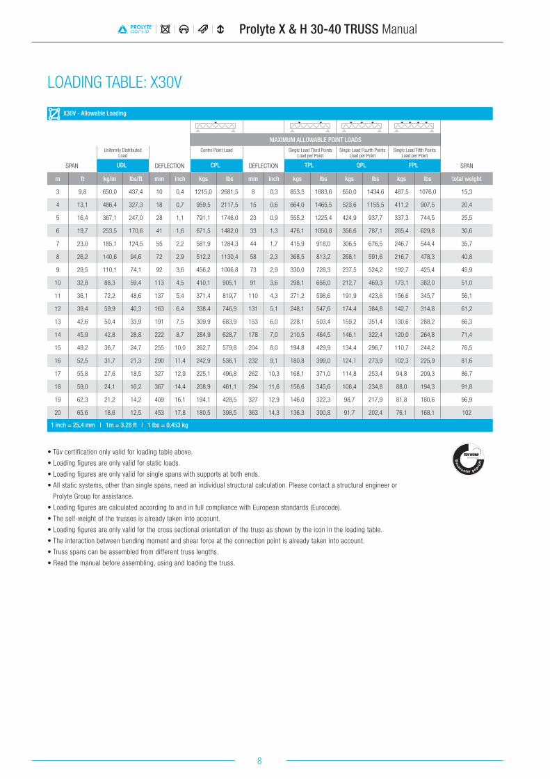
• Tüv certification only valid for loading table above.
• Loading figures are only valid for static loads.
• Loading figures are only valid for single spans with supports at both ends.
• All static systems, other than single spans, need an individual structural calculation. Please contact a structural engineer or
Prolyte Group for assistance.
• Loading figures are calculated according to and in full compliance with European standards (Eurocode).
• The self-weight of the trusses is already taken into account.
• Loading figures are only valid for the cross sectional orientation of the truss as shown by the icon in the loading table.
• The interaction between bending moment and shear force at the connection point is already taken into account.
• Truss spans can be assembled from different truss lengths.
• Read the manual before assembling, using and loading the truss.
APPENDIX A: LOADING TABLE: X30D
8
Prolyte X & H 30-40 TRUSS Manual
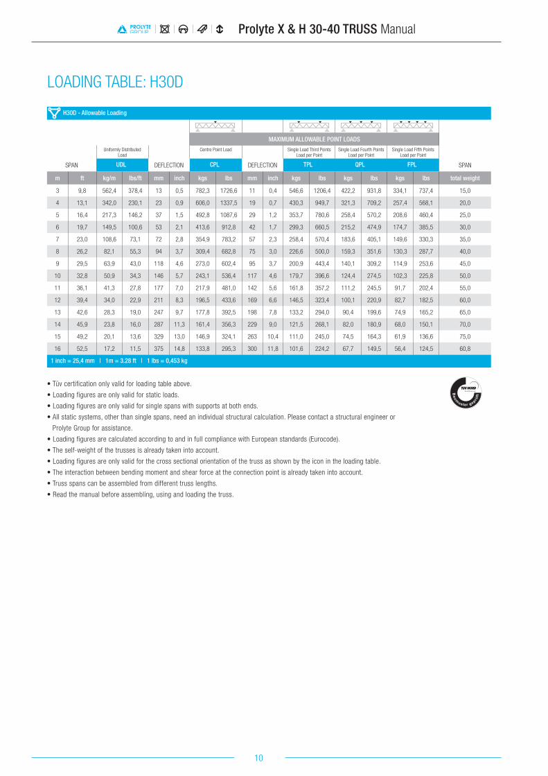
• Tüv certification only valid for loading table above.
• Loading figures are only valid for static loads.
• Loading figures are only valid for single spans with supports at both ends.
• All static systems, other than single spans, need an individual structural calculation. Please contact a structural engineer or
Prolyte Group for assistance.
• Loading figures are calculated according to and in full compliance with European standards (Eurocode).
• The self-weight of the trusses is already taken into account.
• Loading figures are only valid for the cross sectional orientation of the truss as shown by the icon in the loading table.
• The interaction between bending moment and shear force at the connection point is already taken into account.
• Truss spans can be assembled from different truss lengths.
• Read the manual before assembling, using and loading the truss.
X30V - Allowable Loading
MAXIMUM ALLOWABLE POINT LOADS
Uniformly DistributedLoad
Centre Point Load Single Load Third PointsLoad per Point
Single Load Fourth PointsLoad per Point
Single Load Fifth PointsLoad per Point
SPAN UDL DEFLECTION CPL DEFLECTION TPL QPL FPL SPAN
m ft kg/m lbs/ft mm inch kgs lbs mm inch kgs lbs kgs lbs kgs lbs total weight
3 9,8 650,0 437,4 10 0,4 1215,0 2681,5 8 0,3 853,5 1883,6 650,0 1434,6 487,5 1076,0 15,3
4 13,1 486,4 327,3 18 0,7 959,5 2117,5 15 0,6 664,0 1465,5 523,6 1155,5 411,2 907,5 20,4
5 16,4 367,1 247,0 28 1,1 791,1 1746,0 23 0,9 555,2 1225,4 424,9 937,7 337,3 744,5 25,5
6 19,7 253,5 170,6 41 1,6 671,5 1482,0 33 1,3 476,1 1050,8 356,6 787,1 285,4 629,8 30,6
7 23,0 185,1 124,5 55 2,2 581,9 1284,3 44 1,7 415,9 918,0 306,5 676,5 246,7 544,4 35,7
8 26,2 140,6 94,6 72 2,9 512,2 1130,4 58 2,3 368,5 813,2 268,1 591,6 216,7 478,3 40,8
9 29,5 110,1 74,1 92 3,6 456,2 1006,8 73 2,9 330,0 728,3 237,5 524,2 192,7 425,4 45,9
10 32,8 88,3 59,4 113 4,5 410,1 905,1 91 3,6 298,1 658,0 212,7 469,3 173,1 382,0 51,0
11 36,1 72,2 48,6 137 5,4 371,4 819,7 110 4,3 271,2 598,6 191,9 423,6 156,6 345,7 56,1
12 39,4 59,9 40,3 163 6,4 338,4 746,9 131 5,1 248,1 547,6 174,4 384,8 142,7 314,8 61,2
13 42,6 50,4 33,9 191 7,5 309,9 683,9 153 6,0 228,1 503,4 159,2 351,4 130,6 288,2 66,3
14 45,9 42,8 28,8 222 8,7 284,9 628,7 178 7,0 210,5 464,5 146,1 322,4 120,0 264,8 71,4
15 49,2 36,7 24,7 255 10,0 262,7 579,8 204 8,0 194,8 429,9 134,4 296,7 110,7 244,2 76,5
16 52,5 31,7 21,3 290 11,4 242,9 536,1 232 9,1 180,8 399,0 124,1 273,9 102,3 225,9 81,6
17 55,8 27,6 18,5 327 12,9 225,1 496,8 262 10,3 168,1 371,0 114,8 253,4 94,8 209,3 86,7
18 59,0 24,1 16,2 367 14,4 208,9 461,1 294 11,6 156,6 345,6 106,4 234,8 88,0 194,3 91,8
19 62,3 21,2 14,2 409 16,1 194,1 428,5 327 12,9 146,0 322,3 98,7 217,9 81,8 180,6 96,9
20 65,6 18,6 12,5 453 17,8 180,5 398,5 363 14,3 136,3 300,8 91,7 202,4 76,1 168,1 102
1 inch = 25,4 mm | 1m = 3.28 ft | 1 lbs = 0,453 kg
LOADING TABLE: X30V

9
Prolyte X & H 30-40 TRUSS Manual
X30L - Allowable Loading (Span supported on top chord.)
Uniformly DistributedLoad
SPAN UDL DEFLECTION CPL DEFLECTION
m ft kg/m lbs/ft mm inch kgs lbs mm inch
1 3,3 979,7 659,2 2 0,1 979,7 2162,2 1 0,0
2 6,6 345,0 232,1 1 0,1 345,0 761,4 1 0,0
3 9,8 135,0 90,8 3 0,1 203,0 448,0 2 0,1
4 13,1 64,0 43,1 4 0,2 128,0 282,5 3 0,1
5 16,4 27,0 18,2 4 0,2 67,0 147,9 3 0,1
6 19,7 12,0 8,1 4 0,1 36,0 79,5 3 0,1
1 inch = 25,4 mm | 1m = 3.28 ft | 1 lbs = 0,453 kgSpans must be supported at each end.
Loads must be suspended from bottom chord only.
X30L - Allowable Loading (Top chord sideways supported each metre.)
Uniformly DistributedLoad
SPAN UDL DEFLECTION CPL DEFLECTION
m ft kg/m lbs/ft mm inch kgs lbs mm inch
4 13,1 243,2 163,7 18 0,7 459,8 1014,8 15 0,6
5 16,4 176,3 118,6 28 1,1 381,7 842,3 23 0,9
6 19,7 123,2 82,9 41 1,6 325,5 718,3 33 1,3
7 23,0 90,6 61,0 55 2,2 283,0 624,7 44 1,7
8 26,2 69,2 46,6 72 2,9 249,8 551,2 58 2,3
9 29,5 54,4 36,6 92 3,6 222,9 492,0 73 2,9
10 32,8 43,7 29,4 113 4,5 200,7 443,0 91 3,6
11 36,1 35,8 24,1 137 5,4 182,1 401,8 110 4,3
12 39,4 29,8 20,0 163 6,4 166,1 366,5 131 5,1
1 inch = 25,4 mm | 1m = 3.28 ft | 1 lbs = 0,453 kgSpans must be supported at each end.
Loads must be suspended from bottom chord only.
X30L - Allowable Loading (Top chords sideways supported every 2 metres.)
Uniformly DistributedLoad
SPAN UDL DEFLECTION CPL DEFLECTION
m ft kg/m lbs/ft mm inch kgs lbs mm inch
4 13,1 84,6 56,9 5 0,2 169,1 373,3 4 0,2
5 16,4 53,3 35,9 8 0,3 133,3 294,1 7 0,3
6 19,7 36,3 24,4 12 0,5 109,0 240,6 10 0,4
7 23,0 26,1 17,6 17 0,7 91,3 201,6 13 0,5
8 26,2 19,5 13,1 22 0,9 77,8 171,7 17 0,7
9 29,5 14,9 10,0 27 1,1 67,0 148,0 22 0,9
10 32,8 11,6 7,8 34 1,3 58,2 128,4 27 1,1
11 36,1 9,2 6,2 41 1,6 50,8 112,0 33 1,3
12 39,4 7,4 5,0 49 1,9 44,4 97,9 39 1,5
1 inch = 25,4 mm | 1m = 3.28 ft | 1 lbs = 0,453 kgSpans must be supported at each end.
Loads must be suspended from bottom chord only.
1000
1000
1000
1000
2000
2000
2000
2000
LOADING TABLE: X30L
10
Prolyte X & H 30-40 TRUSS Manual
• Tüv certification only valid for loading table above.
• Loading figures are only valid for static loads.
• Loading figures are only valid for single spans with supports at both ends.
• All static systems, other than single spans, need an individual structural calculation. Please contact a structural engineer or
Prolyte Group for assistance.
• Loading figures are calculated according to and in full compliance with European standards (Eurocode).
• The self-weight of the trusses is already taken into account.
• Loading figures are only valid for the cross sectional orientation of the truss as shown by the icon in the loading table.
• The interaction between bending moment and shear force at the connection point is already taken into account.
• Truss spans can be assembled from different truss lengths.
• Read the manual before assembling, using and loading the truss.
H30D - Allowable Loading
MAXIMUM ALLOWABLE POINT LOADS
Uniformly DistributedLoad
Centre Point Load Single Load Third PointsLoad per Point
Single Load Fourth PointsLoad per Point
Single Load Fifth PointsLoad per Point
SPAN UDL DEFLECTION CPL DEFLECTION TPL QPL FPL SPAN
m ft kg/m lbs/ft mm inch kgs lbs mm inch kgs lbs kgs lbs kgs lbs total weight
3 9,8 562,4 378,4 13 0,5 782,3 1726,6 11 0,4 546,6 1206,4 422,2 931,8 334,1 737,4 15,0
4 13,1 342,0 230,1 23 0,9 606,0 1337,5 19 0,7 430,3 949,7 321,3 709,2 257,4 568,1 20,0
5 16,4 217,3 146,2 37 1,5 492,8 1087,6 29 1,2 353,7 780,6 258,4 570,2 208,6 460,4 25,0
6 19,7 149,5 100,6 53 2,1 413,6 912,8 42 1,7 299,3 660,5 215,2 474,9 174,7 385,5 30,0
7 23,0 108,6 73,1 72 2,8 354,9 783,2 57 2,3 258,4 570,4 183,6 405,1 149,6 330,3 35,0
8 26,2 82,1 55,3 94 3,7 309,4 682,8 75 3,0 226,6 500,0 159,3 351,6 130,3 287,7 40,0
9 29,5 63,9 43,0 118 4,6 273,0 602,4 95 3,7 200,9 443,4 140,1 309,2 114,9 253,6 45,0
10 32,8 50,9 34,3 146 5,7 243,1 536,4 117 4,6 179,7 396,6 124,4 274,5 102,3 225,8 50,0
11 36,1 41,3 27,8 177 7,0 217,9 481,0 142 5,6 161,8 357,2 111,2 245,5 91,7 202,4 55,0
12 39,4 34,0 22,9 211 8,3 196,5 433,6 169 6,6 146,5 323,4 100,1 220,9 82,7 182,5 60,0
13 42,6 28,3 19,0 247 9,7 177,8 392,5 198 7,8 133,2 294,0 90,4 199,6 74,9 165,2 65,0
14 45,9 23,8 16,0 287 11,3 161,4 356,3 229 9,0 121,5 268,1 82,0 180,9 68,0 150,1 70,0
15 49,2 20,1 13,6 329 13,0 146,9 324,1 263 10,4 111,0 245,0 74,5 164,3 61,9 136,6 75,0
16 52,5 17,2 11,5 375 14,8 133,8 295,3 300 11,8 101,6 224,2 67,7 149,5 56,4 124,5 60,8
1 inch = 25,4 mm | 1m = 3.28 ft | 1 lbs = 0,453 kg
LOADING TABLE: H30D
11
Prolyte X & H 30-40 TRUSS Manual
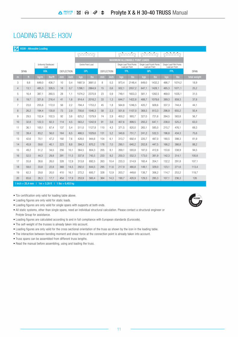
H30V - Allowable Loading
MAXIMUM ALLOWABLE POINT LOADS
Uniformly DistributedLoad
Centre Point Load Single Load Third PointsLoad per Point
Single Load Fourth PointsLoad per Point
Single Load Fifth PointsLoad per Point
SPAN UDL DEFLECTION CPL DEFLECTION TPL QPL FPL SPAN
m ft kg/m lbs/ft mm inch kgs lbs mm inch kgs lbs kgs lbs kgs lbs total weight
3 9,8 649,0 436,7 10 0,4 1667,9 3681,0 8 0,3 973,4 2148,4 649,0 1432,2 486,7 1074,2 18,9
4 13,1 485,3 326,5 18 0,7 1298,1 2864,9 15 0,6 932,1 2057,2 647,1 1428,1 485,3 1071,1 25,2
5 16,4 387,1 260,5 28 1,1 1074,2 2370,9 23 0,9 749,1 1653,3 581,1 1282,5 469,0 1035,1 31,5
6 19,7 321,6 216,4 41 1,6 914,4 2018,2 33 1,3 644,7 1422,8 488,7 1078,6 389,3 859,3 37,8
7 23,0 255,6 172,0 56 2,2 794,4 1753,2 45 1,8 564,8 1246,5 420,7 928,6 337,3 744,4 44,1
8 26,2 194,4 130,8 73 2,9 700,6 1546,3 58 2,3 501,6 1107,0 368,5 813,3 296,9 655,2 50,4
9 29,5 152,4 102,5 92 3,6 625,2 1379,9 74 2,9 450,2 993,7 327,0 721,8 264,5 583,8 56,7
10 32,8 122,3 82,3 114 4,5 563,2 1242,9 91 3,6 407,6 899,5 293,2 647,1 238,0 525,2 63,0
11 36,1 100,1 67,4 137 5,4 511,0 1127,8 110 4,3 371,5 820,0 265,1 585,0 215,7 476,1 69,3
12 39,4 83,2 56,0 164 6,5 466,5 1029,6 131 5,2 340,6 751,7 241,2 532,3 196,8 434,3 75,6
13 42,6 70,1 47,2 192 7,6 428,0 944,6 154 6,1 313,7 692,4 220,7 487,0 180,5 398,3 81,9
14 45,9 59,6 40,1 223 8,8 394,3 870,2 178 7,0 290,1 640,2 202,8 447,5 166,2 366,8 88,2
15 49,2 51,2 34,5 256 10,1 364,5 804,3 205 8,1 269,1 593,8 187,0 412,8 153,6 338,9 94,5
16 52,5 44,3 29,8 291 11,5 337,8 745,5 233 9,2 250,3 552,3 173,0 381,9 142,3 314,1 100,8
17 55,8 38,6 26,0 328 12,9 313,8 692,5 263 10,4 233,3 514,9 160,4 354,1 132,2 291,8 107,1
18 59,0 33,8 22,8 368 14,5 292,0 644,5 295 11,6 217,9 480,8 149,1 329,0 123,1 271,6 113,4
19 62,3 29,8 20,0 410 16,1 272,2 600,7 328 12,9 203,7 449,6 138,7 306,2 114,7 253,2 119,7
20 65,6 26,3 17,7 454 17,9 253,9 560,4 364 14,3 190,7 420,9 129,3 285,3 107,1 236,3 126
1 inch = 25,4 mm | 1m = 3.28 ft | 1 lbs = 0,453 kg
• Tüv certification only valid for loading table above.
• Loading figures are only valid for static loads.
• Loading figures are only valid for single spans with supports at both ends.
• All static systems, other than single spans, need an individual structural calculation. Please contact a structural engineer or
Prolyte Group for assistance.
• Loading figures are calculated according to and in full compliance with European standards (Eurocode).
• The self-weight of the trusses is already taken into account.
• Loading figures are only valid for the cross sectional orientation of the truss as shown by the icon in the loading table.
• The interaction between bending moment and shear force at the connection point is already taken into account.
• Truss spans can be assembled from different truss lengths.
• Read the manual before assembling, using and loading the truss.
LOADING TABLE: H30V

12
Prolyte X & H 30-40 TRUSS Manual
H30L - Allowable Loading (Span supported on top chord.)
Uniformly DistributedLoad
SPAN UDL DEFLECTION CPL DEFLECTION
m ft kg/m lbs/ft mm inch kgs lbs mm inch
1 3,3 979,2 658,9 1 0,0 979,2 2161,2 1 0,0
2 6,6 389,0 261,7 1 0,0 389,0 858,5 1 0,0
3 9,8 156,0 105,0 2 0,1 234,0 516,4 2 0,1
4 13,1 73,0 49,1 3 0,1 146,0 322,2 3 0,1
5 16,4 36,0 24,2 4 0,2 90,0 198,6 3 0,1
6 19,7 15,0 10,1 3 0,1 45,0 99,3 3 0,1
1 inch = 25,4 mm | 1m = 3.28 ft | 1 lbs = 0,453 kgSpans must be supported at each end.
Loads must be suspended from bottom chord only.
H30L - Allowable Loading (Top chord sideways supported each metre.)
Uniformly DistributedLoad
SPAN UDL DEFLECTION CPL DEFLECTION
m ft kg/m lbs/ft mm inch kgs lbs mm inch
4 13,1 242,8 163,4 18 0,7 619,9 1368,1 15 0,6
5 16,4 193,7 130,3 28 1,1 516,7 1140,5 23 0,9
6 19,7 161,0 108,3 41 1,6 442,2 975,9 33 1,3
7 23,0 124,6 83,9 56 2,2 385,6 851,0 45 1,8
8 26,2 95,4 64,2 73 2,9 341,1 752,9 58 2,3
9 29,5 75,1 50,5 92 3,6 305,2 673,6 74 2,9
10 32,8 60,5 40,7 114 4,5 275,5 608,0 91 3,6
11 36,1 49,6 33,4 137 5,4 250,4 552,7 110 4,3
12 39,4 41,4 27,8 164 6,4 229,0 505,3 131 5,2
1 inch = 25,4 mm | 1m = 3.28 ft | 1 lbs = 0,453 kgSpans must be supported at each end.
Loads must be suspended from bottom chord only.
H30L - Allowable Loading (Top chords sideways supported every 2 metres.)
Uniformly DistributedLoad
SPAN UDL DEFLECTION CPL DEFLECTION
m ft kg/m lbs/ft mm inch kgs lbs mm inch
4 13,1 95,2 64,1 4 0,2 190,5 420,3 4 0,1
5 16,4 60,0 40,4 7 0,3 149,9 330,9 6 0,2
6 19,7 40,8 27,5 10 0,4 122,5 270,3 8 0,3
7 23,0 29,3 19,7 14 0,5 102,5 226,1 11 0,4
8 26,2 21,8 14,7 18 0,7 87,1 192,3 14 0,6
9 29,5 16,6 11,2 23 0,9 74,9 165,3 18 0,7
10 32,8 13,0 8,7 28 1,1 64,8 143,1 22 0,9
11 36,1 10,2 6,9 34 1,3 56,4 124,4 27 1,1
12 39,4 8,2 5,5 40 1,6 49,1 108,3 32 1,3
1 inch = 25,4 mm | 1m = 3.28 ft | 1 lbs = 0,453 kgSpans must be supported at each end.
Loads must be suspended from bottom chord only.
1000
1000
1000
1000
2000
2000
2000
2000
LOADING TABLE: H30L

13
Prolyte X & H 30-40 TRUSS Manual
H40D - Allowable Loading
MAXIMUM ALLOWABLE POINT LOADSUniformly Distributed
LoadCentre Point Load Single Load Third Points
Load per PointSingle Load Fourth Points
Load per PointSingle Load Fifth Points
Load per Point
SPAN UDL DEFLECTION CPL DEFLECTION TPL QPL FPL SPAN
m ft kg/m lbs/ft mm inch kgs lbs mm inch kgs lbs kgs lbs kgs lbs total weight
3 9,8 724,4 487,4 9 0,4 1048,3 2313,5 8 0,3 715,6 1579,4 581,4 1283,2 451,7 996,8 15,0
4 13,1 487,6 328,1 17 0,7 824,1 1818,9 13 0,5 573,8 1266,3 446,7 985,8 352,4 777,8 20,0
5 16,4 310,4 208,9 26 1,0 677,3 1494,8 21 0,8 477,8 1054,6 361,7 798,2 288,3 636,3 25,0
6 19,7 214,2 144,1 38 1,5 573,4 1265,4 30 1,2 408,5 901,5 303,0 668,8 243,3 536,9 30,0
7 23,0 156,2 105,1 51 2,0 495,7 1094,1 41 1,6 355,9 785,4 260,0 573,8 209,9 463,2 35,0
8 26,2 118,5 79,8 64 2,5 435,3 960,7 53 2,1 314,5 694,1 226,9 500,9 184,0 406,0 40,0
9 29,5 92,7 62,4 85 3,3 386,8 853,8 68 2,7 281,0 620,2 200,7 443,0 163,3 360,4 45,0
10 32,8 74,2 50,0 104 4,1 347,0 765,8 84 3,3 253,3 558,9 179,3 395,8 146,3 323,0 50,0
11 36,1 60,6 40,8 126 5,0 313,5 691,9 101 4,0 229,8 507,3 161,5 356,5 132,1 291,6 55,0
12 39,4 50,2 33,8 150 5,9 284,9 628,9 120 4,7 209,8 463,0 146,4 323,1 120,1 265,0 60,0
13 42,6 42,1 28,3 176 6,9 260,2 574,3 141 5,6 192,3 424,5 133,4 294,3 109,6 241,9 65,0
14 45,9 35,7 24,0 205 8,1 238,5 526,4 164 6,5 177,0 390,6 122,0 269,2 100,5 221,7 70,0
15 49,2 30,5 20,5 235 9,3 219,3 484,0 188 7,4 163,3 360,5 111,9 247,1 92,4 203,9 75,0
16 52,5 26,3 17,7 267 10,5 202,1 446,0 214 8,4 151,1 333,5 103,0 227,3 85,1 187,9 80,0
17 55,8 22,7 15,3 302 11,9 186,6 411,7 241 9,5 140,0 309,0 94,9 209,5 78,6 173,5 85,0
18 59,0 19,8 13,3 338 13,3 172,4 380,6 271 10,7 129,9 286,8 87,6 193,4 72,7 160,5 90,0
19 62,3 17,3 11,6 377 14,8 159,5 352,1 302 11,9 120,7 266,3 81,0 178,7 67,3 148,5 95,0
20 65,6 15,2 10,2 417 16,4 147,6 325,8 334 13,1 112,1 247,5 74,9 165,2 62,3 137,5 100,0
1 inch = 25,4 mm | 1m = 3.28 ft | 1 lbs = 0,453 kg
• Tüv certification only valid for loading table above.
• Loading figures are only valid for static loads.
• Loading figures are only valid for single spans with supports at both ends.
• All static systems, other than single spans, need an individual structural calculation. Please contact a structural engineer or
Prolyte Group for assistance.
• Loading figures are calculated according to and in full compliance with European standards (Eurocode).
• The self-weight of the trusses is already taken into account.
• Loading figures are only valid for the cross sectional orientation of the truss as shown by the icon in the loading table.
• The interaction between bending moment and shear force at the connection point is already taken into account.
• Truss spans can be assembled from different truss lengths.
• Read the manual before assembling, using and loading the truss.
LOADING TABLE: H40D

14
Prolyte X & H 30-40 TRUSS Manual
H40V - Allowable Loading
MAXIMUM ALLOWABLE POINT LOADSUniformly Distributed
LoadCentre Point Load Single Load Third Points
Load per PointSingle Load Fourth Points
Load per PointSingle Load Fifth Points
Load per Point
SPAN UDL DEFLECTION CPL DEFLECTION TPL QPL FPL SPAN
m ft kg/m lbs/ft mm inch kgs lbs mm inch kgs lbs kgs lbs kgs lbs total weight
3 9,8 835,4 562,1 7 0,3 2198,9 4853,1 6 0,2 1253,2 2765,8 835,4 1843,8 626,6 1382,9 20,7
4 13,1 625,0 420,6 13 0,5 1712,4 3779,2 10 0,4 1215,1 2681,7 833,4 1839,3 625,0 1379,5 27,6
5 16,4 498,8 335,6 20 0,8 1435,8 3168,9 16 0,6 994,0 2193,8 815,2 1799,1 623,5 1376,0 34,5
6 19,7 414,6 279,0 29 1,1 1234,4 2724,4 23 0,9 851,7 1879,7 676,0 1492,0 529,7 1169,0 41,4
7 23,0 354,5 238,5 40 1,6 1080,9 2385,6 32 1,2 753,5 1663,0 585,0 1291,2 462,0 1019,6 48,3
8 26,2 277,5 186,7 52 2,0 959,8 2118,3 41 1,6 674,7 1489,0 514,7 1136,0 409,1 902,8 55,2
9 29,5 218,0 146,7 65 2,6 861,7 1901,7 52 2,1 609,9 1346,1 458,7 1012,3 366,4 808,7 62,1
10 32,8 175,4 118,0 81 3,2 780,4 1722,3 65 2,5 555,7 1226,4 412,9 911,3 331,2 731,0 69,0
11 36,1 143,9 96,8 98 3,8 711,8 1570,9 78 3,1 509,5 1124,6 374,7 827,0 301,7 665,8 75,9
12 39,4 119,9 80,7 116 4,6 653,1 1441,4 93 3,7 469,7 1036,7 342,3 755,5 276,5 610,2 82,8
13 42,6 101,2 68,1 137 5,4 602,2 1328,9 109 4,3 435,0 960,0 314,4 693,9 254,7 562,1 89,7
14 45,9 86,4 58,2 158 6,2 557,5 1230,3 127 5,0 404,3 892,3 290,1 640,3 235,6 519,9 96,6
15 49,2 74,5 50,1 182 7,2 517,9 1143,0 146 5,7 377,0 832,1 268,8 593,1 218,7 482,7 103,5
16 52,5 64,7 43,5 207 8,1 482,5 1064,9 166 6,5 352,5 778,0 249,8 551,2 203,7 449,6 110,4
17 55,8 56,6 38,1 234 9,2 450,7 994,7 187 7,4 330,4 729,2 232,7 513,7 190,2 419,7 117,3
18 59,0 49,8 33,5 262 10,3 421,8 931,0 210 8,3 310,3 684,8 217,4 479,7 178,0 392,8 124,2
19 62,3 44,1 29,7 292 11,5 395,5 872,8 233 9,2 291,9 644,1 203,4 448,9 166,8 368,2 131,1
20 65,6 39,2 26,4 323 12,7 371,3 819,5 259 10,2 274,9 606,7 190,7 420,8 156,6 345,7 138,0
1 inch = 25,4 mm | 1m = 3.28 ft | 1 lbs = 0,453 kg
• Tüv certification only valid for loading table above.
• Loading figures are only valid for static loads.
• Loading figures are only valid for single spans with supports at both ends.
• All static systems, other than single spans, need an individual structural calculation. Please contact a structural engineer or
Prolyte Group for assistance.
• Loading figures are calculated according to and in full compliance with European standards (Eurocode).
• The self-weight of the trusses is already taken into account.
• Loading figures are only valid for the cross sectional orientation of the truss as shown by the icon in the loading table.
• The interaction between bending moment and shear force at the connection point is already taken into account.
• Truss spans can be assembled from different truss lengths.
• Read the manual before assembling, using and loading the truss.
LOADING TABLE: H40V

15
Prolyte X & H 30-40 TRUSS Manual
H40L - Allowable Loading (Span supported on top chord.)
Uniformly DistributedLoad
SPAN UDL DEFLECTION CPL DEFLECTION
m ft kg/m lbs/ft mm inch kgs lbs mm inch
1 3,3 1259,8 847,7 1 0,0 1259,8 2780,4 0 0,0
2 6,6 629,0 423,2 1 0,0 629,0 1388,2 1 0,0
3 9,8 253,0 170,2 2 0,1 380,0 838,7 1 0,1
4 13,1 105,0 70,7 2 0,1 210,0 463,5 2 0,1
5 16,4 52,0 35,0 3 0,1 130,0 286,9 2 0,1
6 19,7 24,0 16,1 3 0,1 72,0 158,9 2 0,1
1 inch = 25,4 mm | 1m = 3.28 ft | 1 lbs = 0,453 kgSpans must be supported at each end.
Loads must be suspended from bottom chord only.
H40L - Allowable Loading (Top chord sideways supported each metre.)
Uniformly DistributedLoad
SPAN UDL DEFLECTION CPL DEFLECTION
m ft kg/m lbs/ft mm inch kgs lbs mm inch
4 13,1 312,9 210,6 13 0,5 806,8 1780,5 10 0,4
5 16,4 249,8 168,1 20 0,8 682,7 1506,7 16 0,6
6 19,7 207,7 139,8 29 1,1 590,9 1304,1 23 0,9
7 23,0 173,4 116,7 40 1,6 520,2 1148,0 32 1,2
8 26,2 133,7 90,0 52 2,0 463,9 1023,7 41 1,6
9 29,5 106,0 71,3 65 2,6 417,9 922,4 52 2,1
10 32,8 85,8 57,7 81 3,2 379,7 838,0 65 2,5
11 36,1 70,8 47,6 98 3,8 347,3 766,5 78 3,1
12 39,4 59,2 39,9 116 4,6 319,5 705,1 93 3,7
1 inch = 25,4 mm | 1m = 3.28 ft | 1 lbs = 0,453 kgSpans must be supported at each end.
Loads must be suspended from bottom chord only.
H40L - Allowable Loading (Top chords sideways supported every 2 metres.)
Uniformly DistributedLoad
SPAN UDL DEFLECTION CPL DEFLECTION
m ft kg/m lbs/ft mm inch kgs lbs mm inch
4 13,1 156,2 105,1 4 0,1 312,5 689,6 3 0,1
5 16,4 99,0 66,6 6 0,2 247,5 546,3 5 0,2
6 19,7 67,9 45,7 8 0,3 203,8 449,8 7 0,3
7 23,0 49,2 33,1 11 0,4 172,2 380,0 9 0,3
8 26,2 37,0 24,9 14 0,6 148,1 326,9 12 0,5
9 29,5 28,7 19,3 18 0,7 129,1 285,0 15 0,6
10 32,8 22,7 15,3 23 0,9 113,6 250,8 18 0,7
11 36,1 18,3 12,3 27 1,1 100,7 222,3 22 0,9
12 39,4 15,0 10,1 33 1,3 89,8 198,1 26 1,0
1 inch = 25,4 mm | 1m = 3.28 ft | 1 lbs = 0,453 kgSpans must be supported at each end.
Loads must be suspended from bottom chord only.
1000
1000
1000
1000
2000
2000
2000
2000
LOADING TABLE: H40L
16
Prolyte X & H 30-40 TRUSS Manual
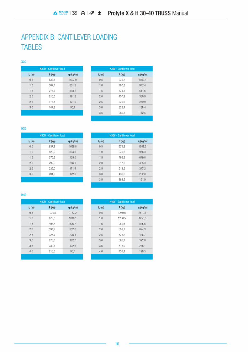
X30
H30
H40
X30D - Cantilever load
lk (m) P (kg) q (kg/m)
0,5 633,5 1697,9
1,0 387,1 631,2
1,5 277,6 318,2
2,0 215,6 191,2
2,5 175,4 127,0
3,0 147,2 90,1
H30D - Cantilever load
lk (m) P (kg) q (kg/m)
0,5 837,8 1696,8
1,0 520,0 834,8
1,5 375,6 425,0
2,0 292,9 256,9
2,5 239,0 171,4
3,0 201,0 122,0
H40D - Cantilever load
lk (m) P (kg) q (kg/m)
0,5 1020,9 2182,2
1,0 670,0 1018,1
1,5 497,4 536,7
2,0 394,4 332,0
2,5 325,7 225,4
3,0 276,6 162,7
3,5 239,6 122,6
4,0 210,6 95,4
X30V - Cantilever load
lk (m) P (kg) q (kg/m)
0,5 979,7 1959,4
1,0 767,8 977,4
1,5 574,5 611,6
2,0 457,9 380,9
2,5 379,6 259,9
3,0 323,4 188,4
3,5 280,8 142,5
H30V - Cantilever load
lk (m) P (kg) q (kg/m)
0,5 979,2 1958,3
1,0 979,2 976,3
1,5 769,9 649,0
2,0 617,2 485,3
2,5 513,9 347,2
3,0 439,2 252,8
3,5 382,5 191,9
H40V - Cantilever load
lk (m) P (kg) q (kg/m)
0,5 1259,6 2519,1
1,0 1256,5 1256,5
1,5 980,6 835,6
2,0 802,7 624,3
2,5 678,2 436,7
3,0 586,1 322,8
3,5 515,0 248,1
4,0 458,4 196,5
APPENDIX B: CANTILEVER LOADING TABLES

17
Prolyte X & H 30-40 TRUSS Manual
Prolyte Group HQ Leek, Netherlands [email protected]
WWW.PROLYTE.COM FACEBOOK.COM/PROLYTEGROUP TWITTER.COM/PROLYTE