ASSEMBLY AND INSTALLATION INSTRUCTIONS - … MANUALS/CUSHCRAFT/CUSHCRAFT--R8 … · ASSEMBLY AND...
14
951489 (12/99) 6,10, 12, 15, 17, 20, 30, 40, Meters ASSEMBLY AND INSTALLATION INSTRUCTIONS
Transcript of ASSEMBLY AND INSTALLATION INSTRUCTIONS - … MANUALS/CUSHCRAFT/CUSHCRAFT--R8 … · ASSEMBLY AND...

951489 (12/99)
6,10, 12, 15, 17, 20, 30, 40, Meters
ASSEMBLY AND INSTALLATIONINSTRUCTIONS

1
WARNINGTHIS ANTENNA IS AN ELECTRICAL CONDUCTOR. CONTACT WITH POWER LINES CAN RESULT IN DEATH, OR SERIOUS INJURY. DO NOT INSTALL THIS ANTENNA WHERE THERE IS ANY POSSIBILITY OF CONTACT WITH HIGH VOLTAGE OR ARC-OVER FROMPOWER CABLES OR SERVICE DROPS TO BUILDINGS. THE ANTENNA, SUPPORTING MAST AND/OR TOWER MUST NOT BECLOSE TO ANY POWER LINES DURING INSTALLATION, REMOVAL OR IN THE EVENT PART OF THE SYSTEM SHOULDACCIDENTALLY FALL. FOLLOW THE GUIDELINES FOR ANTENNA INSTALLATIONS RECOMMENDED BY THE U.S. CONSUMERPRODUCT SAFETY COMMISSION AND LISTED IN THE ENCLOSED PAMPHLET.
R8
Your Cushcraft R8 vertical antenna is designed and manufactured to give trouble free service. This antennawill perform as specified if the instructions and suggestions in this manual are followed and care is usedin the assembly and installation. When checking the components received in your antenna package usethe parts listed beside each diagram. There is a master parts list on page 2. If you are unable to locateany tube or component, check the inside of all tubing. IMPORTANT: Save the weight label from the outsideof the carton. Each antenna is weighed at the factory to verify the parts count. If you claim a missing part,you will be asked for the weight verification label.
PLANNINGPlan your installation carefully. If you use volunteer helpers be sure that they are qualified to assist you. Make certain that everyone involved understands that you are the boss and that they must follow yourinstructions. If you have any doubts at all, employ a professional antenna installation company to installyour antenna.
LOCATIONAlthough the R8 will operate in almost any location, it will perform best if it is mounted vertically and locatedin the clear away from surrounding objects such as buildings, trees, power lines, towers, guy wires, antennasand metallic objects.
EXTREME CARE MUST BE USED FOR YOUR SAFETY. YOU MUST INSURE THAT WHILE THE R8IS IN OPERATION NEITHER PEOPLE NOR PETS CAN COME IN CONTACT WITH ANY PORTION OFYOUR ANTENNA INCLUDING THE COUNTERPOISE RODS. DEADLY VOLTAGES AND CURRENTSMAY EXIST. ALSO, SINCE THE EFFECTS OF EXPOSURE TO RF ARE NOT FULLY UNDERSTOOD,LONG TERM EXPOSURE TO INTENSE RF FIELDS IS NOT RECOMMENDED. THERE ARE SEVENWARNING STICKERS WHICH MUST BE ATTACHED TO THE ENDS OF THE COUNTERPOISE RODSAS SHOWN IN FIGURE E.
MOUNTINGYour mast should be rigid and pointing straight up. Always use a mast at least 1-3/4 inches (4.4 cm) butnot larger than 2-1/8 inches (5.4 cm) in diameter. If you guy the mast, use nonconducting guy wires.
SYSTEM GROUNDINGDirect grounding of the antenna mast is very important. This serves as protection from lightning strikesand static buildup, and from high voltages which may be present in the equipment attached to the antenna. A good electrical connection should be made to one or more ground rods directly at the base of the antennaor mast using a least #10 AWG ground wire and noncorrosive hardware. For details and safety standards,consult the National Electrical Code. You should also use a coaxial lightning arrestor. Cushcraft offersseveral different models, such as the LAC-1, LAC-2 or the LAC-4 series.
ASSEMBLYAssemble your R8 by following steps 1 through 12. After assembling the antenna, verify all dimensionsfor accuracy.

2
MASTER PARTS LIST
BA Base assembly 1BB R8 Tube BB 1-1/4” x 72”( 3.17 x 182.9cm) 1BC R8 Tube BC 1-1/8” x 72”(2.9 x 182.9cm) 1BD R8 Tube BD 1” x 36” (2.5 x 91cm) 1BE R8 Tube BE 7/8” x 16” (2.3 x 40.5cm) 1BF R8 Tube BF 7/8” Swedged x 10-3/4” (2.3 x 27.3cm) 1BG R8 Tube BG 1/2” x 24” (1.2 x 61cm) 1BH R8 Tube BH 3/8” x 24” (0.9 x 61cm) 1SA R8 Stub SA 3/8” x 52” (0.9 x 132cm) 1SB R8 Stub SB 1/4” x 6” (0.6 x 15cm) 6SC R8 Stub SC 3/8” x 48” (0.9 x 121.9cm) 1SD R8 Stub SD 1/4” x 48” (0.6 x 121.9cm) 1SE R8 Stub SE 1/4” x 12” (0.6 x 30cm) 1SF R8 Stub SF 3/8” x 72” (0.9 x 182.8cm) 2SG R8 Stub SG 3/8” x 43-1/2” (0.9 x 110.5cm) 1SH R8 Stub SH 3/8” x 68” (0.9 x 173cm) 1BT1 BT1 Trap 17 / 20 Meter 1BT2 BT2 Trap 30 Meter 1MN8 R8 Matching Network 1XHR32 32” X-Hat Rod 2XHR40 40” X-Hat Rod 209 010009 # 8-32 x 5/8” SS RH MS 1211 010011 # 8-32 SS Hex Nut 1826 190026 Aluminum Bracket 428 190028 Aluminum Half Washer 432 902832 49” Whip & Tip Assembly 763 170063 Extruded Aluminum V-Block 464 014764 # 8-32 x 2-1/4” SS Machine Screw 273 194173 Radial Ring Bracket 474 194174 Radial Ring 276 054276 3/8” x 7/8” Black plastic Cap 187 014387 # 8-32 x SS/Nylon Hex Nut 2196 010096 # 8-32 x 3/8” SS RH MS 499 205099 Aluminum Stub Clamp 2105 055105 1/4” Black Plastic Cap 4115 050115 Connector Boot 1116 240116 Silicone Package 1120 010120 # 8-32 x 2” SS RH MS 1160 190160 Matching Network Bracket 1220 010220 # 10-24 SS Hex Nut 1231 010231 # 8-32 x 1-3/4” SS RH MS 7232 010232 # 8-32 x 2-1/2” SS RH MS 6233 010233 # 10 SS Split Lock Washer 1326 290326 Danger Label 8389 014389 5/16-18 SS/Nylon Hex Nut 8404 010404 U-Bolt SS 5/16-18 3-1/4 (2-7/16 C-C) 2405 010405 U-bolt SS 5/16-18 4-1/2 (2-7/16 C-C) 2407 030407 Worm Clamp SS 7/32” - 5/8” 10409 030409 Worm Clamp SS 3/8” - 7/8” 2410 030410 Worm Clamp SS 7/16” - 1” 3411 030411 Worm Clamp SS 9/16” - 1-1/4” 2412 030412 Worm Clamp SS 11/16” - 1-1/2” 1413 030413 Worm Clamp SS 3/4” - 1-3/4” 1428 902428 Ground Strap 1657 194657 Aluminum L Bracket 6940 360940 # 8 Aluminum Flat Washer 12941 011941 # 8 SS Split Lock Washer 184079 194079 Aluminum Mounting Plate 15072 205072 4-Hole Insulator 15096 205096 3-Hole Insulator 15097 205097 2-Hole Insulator 1
KEY PART# DESCRIPTION QTY
R8

BA
3
#1 - ASSEMBLE RADIALRINGS
232
232
8787
428
73
232
232
232
232
8787
87
87
87
96
87
96
8787
79
74
73
7973
FIGURED
FIGUREA
FIGUREC
FIGUREB
73 73
R8
Figures A through D show the steps for radial ring assembly. Referto the parts table below for the parts required in this step. Slidethe two radial rings (74) onto the base assembly (BA). Note theorientation of the ring slots. Attach the rings to the base using theradial ring brackets (73), 2 1/2" screws (232), 1/2" screws (79)and lock nuts (87). Leave hardware loose until Step #2. Note theproper orientation of the radial ring brackets in Figure A. Installground strap (428) as shown in Figure D.
NOTE: Do not accidentally use the #10-24 nut inthis step.
Insert four 2 1/2" screws (232) into the base assembly (BA) asshown in Figure D. Secure with nuts (87).
73 194173 RADIAL RING 4
96 010096 SS MACHINE #8-32 x 3/8” 4SCREW (.95 cm)
BA BASE 1ASSEMBLY
BRACKET
74 194174 RADIAL RING 2
79 010079 SS MACHINE # 8-32 x 1/2 4SCREW (1.3 cm)
87 014387 SS LOCK # 8-32 14NUT
232 010232 SS MACHINE # 8-32 x 2-1/2" 6SCREW (6.35 cm)
428 902428 GROUND STRAP 1
KEY P/N DISPLAY DESC SIZE QTY
Longer dimensionattaches to base.
Shorterdimensionattaches toradial ring.
4
32 902832 SS RADIAL 49" 7(124.5 cm)
BRACKET
87 014387 SS LOCK #8-32 4NUT
326 290326 WARNING 7LABEL
MN MN8 MATCHING 1NETWORK
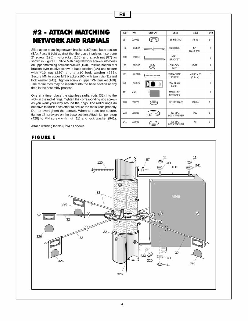
#2 - ATTACH MATCHINGNETWORK AND RADIALS
KEY P/N DISPLAY DESC SIZE QTY
FIGURE E
190160160
220 010220 SS HEX NUT #10-24 1
233 010233 SS SPLIT #10 1LOCK WASHER
941 011941 SS SPLIT #8 3LOCK WASHER
11 010011 SS HEX NUT #8-32 3
11 11
MN8
220
32
32
32
32
32611
32
326
326
326
326
160120
87941941
941233
1MN8
Slide upper matching network bracket (160) onto base section(BA). Place it tight against the fiberglass insulator. Insert one2" screw (120) into bracket (160) and attach nut (87) asshown in Figure E. Slide Matching Network screws into holeson upper matching network bracket (160). Position bottom MNbracket over captive screw in base section (BA) and securewith #10 nut (220) and a #10 lock washer (233).Secure MN to upper MN bracket (160) with two nuts (11) andlock washer (941). Tighten screw in upper MN bracket (160).The radial rods may be inserted into the base section at anytime in the assembly process.
One at a time, place the stainless radial rods (32) into theslots in the radial rings. Tighten the corresponding ring screwsas you work your way around the rings. The radial rings donot have to touch each other to secure the radial rods properly.Do not overtighten the screws. When all rods are secure,tighten all hardware on the base section. Attach jumper strap(428) to MN screw with nut (11) and lock washer (941).
Attach warning labels (326) as shown.
R8
120 010120 SS MACHINE # 8-32 x 2” 1SCREW (5.1 cm)

114 PLACES
9414 PLACES
5
#3 - ASSEMBLE PLASTICSPACERS TO RADIAL RINGS
09 010009 SS Machine # 8-32 x 5/8” 12Screw (1.6 cm
11 010011 SS HEX NUT 8-32 15
941 011941 SS Split Lock # 8 15Washer
231 010231 SS Machine 8-32 x 1-3/4” 3Screw (4.45 cm)
657 194657 Aluminum 6L Bracket
940 360940 Aluminum # 8 12Flat Washer
BB R8BB R8 Tube 1-1/4” x 72” 1(3.2 x 182.9 cm)
BC R8BC R8 Tube 1-1/8” x 72” 1(2.9 x 182.9 cm)
5072 205072 4-Hole 1Insulator
5096 205096 3-Hole 1Insulator
5097 205097 2-Hole 1Insulator
KEY P/N DISPLAY DESC SIZE QTY
6572 PLACES
R8
941
11 231
114 PLACES
9404 PLACES
5072
094 PLACES
BBBB
231
231941
11
6572 PLACES
6572 PLACES
5096
5097
BCBC
114 PLACES
9404 PLACES
9404 PLACES
094 PLACES
094 PLACES
9414 PLACES
9414 PLACES
941
11
Place the aluminum L-brackets (657) on tube (BB) and secure themwith hardware (231,941&11). Repeat this as well on tube (BC) asshown on Fig. "F". Slide the 4-hole insulator (5072) on tube (BB)and secure it with applicable hardware ( 09, 940,941 & 11). Repeatthe same with two and three hole insulators (5096 & 5097) ontube (BC) according the Fig. "F".
NOTE: Make sure that the tubes are oriented with the slotted endson the top when you start assembling the hardware onto them.
FIGURE F

413
BA
BB
BD
411
412
BC
4-1/2”INSERT(11.4 cm)
BA
BB
8”INSERT
BB
BC
BB
BC
6
#4 - ASSEMBLE RADIATOR TUBES
BA BASE 1ASSEMBLY
BB R8 TUBE BB 1-1/4” x 72” 1(3.17 x 182.9 cm)
BC R8 TUBE BC 1-1/8” x 72” 1(2.9 x 182.9 cm)
BD R8 TUBE BD 1” x 36” 1(2.5 x 91 cm)
411 030411 SS WORM 9/16” x 1-1/4” 1CLAMP (1.4 x 3.1 cm)
412 030412 SS WORM 11/16” x 1-1/2” 1CLAMP (0.7 x 3.8 cm)
413 030413 SS WORM 3/4” x 1-3/4” 1CLAMP (1.9 x 4.4 cm)
KEY P/N DISPLAY DESC SIZE QTY
Slide the Tube BD into tube BC until it hits the inner tube, and secure itwith worm clamp (411). Slide this assembly into tube BB and secure itwith worm clamp (412). Make sure that plastic insulators are aligned asshown in Fig. "G".
Insert assembly consisted of tubes BD, BC and BB 4 -1/2 " into baseassembly (BA) and secure it with worm clamp (413).We recommendthat you use workhorses or two chairs to place this assembly in a horizontalposition . You may or may not attach the stainless radial rods (32) to thebase assembly (BA) at this time as mentioned in Section #2 of thismanual.
FIGURE G
R8

64
15-3/8”(39.1 cm)
LOWER BRACKETSITS FLUSH ONBASE ASSEMBLY
87 64
99
87
99
7
#5 - ASSEMBLE METALCLAMPS ON TO RADIATORAs the antenna radiator sits on workhorses or pair of chairs place thealuminum stub clamps (99) on radiator according the Fig. "H". Makesure the clamps are aligned as shown. Leave the hardware on clamps(64, 87) slightly loose to allow you insert the stub tubes later.
R8
FIGURE H
64 014764 SS MACHINE #8-32 x 2-1/4” 4SCREW (5.7 cm)
87 014387 SS NYLON #8-32 4HEX NUT
99 205099 ALUMINUM 2STUB CLAMP
KEY P/N DISPLAY DESC SIZE QTY

8
#6 - ASSEMBLY OF 6 AND10 METERS STUBS
SA R8SA R8 Stub SA 3/8” x 52” 1(1 x 132 cm)
SB R8SB R8 Stub SB 1/4” x 6” 2(0.6 x 15 cm)
SC R8SC R8 Stub SC 3/8” x 48” 1(1 x 121.9 cm)
SD R8SD R8 Stub SD 3/8” x 48” 1(1 x121.9 cm)
SE R8SE R8 Stub SE 1/4” x 12” 1(.6 x 30.5 cm)
105 055105 Black Plastic Cap 1/4” 2(.6 cm)
407 030407 SS Worm Clamp 7/32”-5/8” 4(.6 x 1.6 cm)
KEY P/N DISPLAY DESC SIZE QTY
Take the (SA) tube and slide it through the 4-hole insulator and secureit in the bottom aluminum stub clamp as shown in Fig. "I". Make surethat the slotted end of (SA) tube protrudes beyond the 4-hole insulatorand the opposite end of (SA) tube is mounted flush with the bottomof the stub clamp (see callout at bottom of Fig I). In same fashionslide the tube (SC) and secure it on other side of bottom aluminumstub clamp. Align the bottom stub clamp with plastic insulators andsecure it tight. Slide the 6" rod (SB) into tube (SA) and secure withworm clamp (407). Use 6 Meter tuning chart to adjust the stub (SB)for selected portion of the band. Place the protective plastic cap ontop of (SB) tuning rod to complete the 6 Meter stub.
Take another 6" rod (SB) and slide it 3" into tube (SC) and secure withworm clamp (407) as shown in callout of Fig. "I". Slide the tube (SD)through 3-hole plastic insulator and assemble with worm clamp (407)over other end of rod (SB). Insert rod ( SE) into tube (SD) as shown,and complete the 10 Meter stub by placing the protective plastic capon top.
FIGURE I
Frequency (MHz) Length50.250 4-1/2” (11.4 cm)50.800 3-1/2” (8.9 cm)51.500 2-1/2” (6.4 cm)52.500 1-1/2” (13.8 cm)53. 500 1/2” (1.3 cm)
6 Meter Tune Chart
R8
3” (7.6 cm)INSERT
3” (7.6 cm)INSERT
10” (25.4 cm)EXPOSED
SEE 6 METERTUNE CHART
105
SE
407
407
407
105
SB
SB
407
SD
SC
SA
SCSA
99
Stubs sit flush with bottom ofstub clamp.
NOTE:
BB
BA

9
#7 - ASSEMBLY OF 12 AND15 METERS STUBS
KEY P/N DISPLAY DESC SIZE QTY
3” (7.6 cm)INSERT
SB R8SB R8 STUB SB 1/4” x 6” 4(.6 x 15 cm)
105 055105 BLACK PLASTIC 1/4” 2CAP (.6 cm)
407 030407 SS WORM 7/32”-5/8” 6CLAMP (1.2 x 1.6 cm)
SF R8SF R8 STUB SF 3/8” x 72” 2(1 x 182.9 cm)
SH R8SH R8 STUB SH 3/8” x 68” 1(1 x173 cm)
SG R8SG R8 STUB SG 3/8” x 43-1/2” 1(1 x110.5 cm)
3” (7.6 cm)INSERT
407 407
SGSH
SF
SF
Take two tubes (SF) and slide them through 4-hole plastic insulatorand secure in top stub clamp as shown in Fig. J1. Insert two6"rods (SB) in (SF) tubes and place the worm clamps (407) asshown in callout at Fig. J2. Place tube (SH) on left side stub asshown in Fig. J2, sliding it through 2 and 3 hole plastic insulators.Insert tube (SG) on the right side stub as shown and secure withworm clamp. Take two (SB) rods and insert them on top of thesetwo stubs as shown in top callouts of Fig. J2 along with protectiveend caps.
Note: Make sure that all stubs are positioned around main radiatoras shown in Fig. J2
FIGURE J1
R8
FIGURE J2
3-1/2” (8.9 cm)EXPOSED
3” (7.6 cm)INSERT
3” (7.6 cm)INSERT
3-1/2” (8.9 cm)EXPOSED
105105
SB SB
SB SB
407407
SF SF

10
#8 - ASEEMBLE X-HAT ONBD TUBEInstall 2 X hat rods (XHR40) as shown in figure K, using aluminumbracket, (26), aluminum half washers (28), and fasten with screw(231) and lock nut (87).
FIGURE K
R8
KEY P/N DISPLAY DESC SIZE QTY
XHR40 XHR40 X-Hat Rod 40” (101.6 cm) 2
26 190026 Aluminum 2Bracket
28 190028 Aluminum 2Half Washer
87 014387 SS Nylon # 8-32 2Hex Nut
231 010231 SS RH #8-32 x 1-3/4” 2Machine Screw (4.4 cm)
28
8787
231
231
26
28
XRH40
26
XRH40
BD

11
#9 - ASSEMBLE TRAPS
#10 - ASSEMBLE TOP RADIATOR WITH X-HAT
18”(45.7 cm)
BT2
BT1
BE
410
410
411
BT1 BT1 TRAP 117/20 METER
BT2 BT2 TRAP 130 METER
BE R8 TUBE 7/8” x 16” 1BE (2.3 x 41 cm)
410 030410 SS WORM 7/16”-1” 2CLAMP (1.1 x 2.5cm)
411 030411 SS WORM 9/16” x 1-1/4” 1CLAMP (1.4 x 3.2 cm)
KEY P/N DISPLAY DESC SIZE QTY
SEE 40 METERTUNE CHART
22”(55.4 cm)
XHR32 XHR32 X-HAT ROD 32” (81 cm) 2
26 190026 ALUMINUM 2BRACKET
28 190028 ALUMINUM 2Half Washer
76 054276 END CAP 3/8” 1( 0.9 cm)
87 014387 SS NYLON # 8-32 2HEX NUT
231 010231 SS RH # 8-32 x 1-3/4” 2MACHINE SCREW (4.4 cm)
409 030409 SS WORM 3/8”-7/8” 1CLAMP (0.9 x 2.2 cm)
410 030410 SS WORM 7/16”-1” 1CLAMP (1.1 x 2.5 cm)
BG R8BG R8 TUBE BG 1/2” x 24” 1(1.3 x 61 cm)
BH R8BH R8 TUBE BH 3/8” x 24” 1(0.9 x 61 cm)
KEY P/N DISPLAY DESC SIZE QTY
XHR32
28
8787
2 3 1
231
26
28
XHR32
2 6
1”(2.5 cm)
BG
BH
76
409
409
410
BF
BT2
Assemble traps (BT1) and (BT2) as shown in callout of Fig."L". Slidethis assembly into top tube (BD) of main radiator assembly until it hitsthe screws of X-hat assembly and secure it with worm clamp (411).
Take the tube (BG) and insert 2" into swedged tube (BF). Secure assemblywith worm clamp (409). Slide tube (BH) into tube (BG) and adjust forselected portion of 40 Meters band according the 40 Meter Tuning chart.Install X-hats (XHR32) on swedged tube (BF) as shown in callout ofFig."M". Take this assembly and slide it over top trap (BT2) spacing theedge of (BF) 1" of the trap cap.
FIGURE L
FIGURE M
Frequency (MHz) Length (In) (cm)7.025 20” (50.8)7.050 18.5” (47.0)7.100 16” (40.6)7.150 13” (33.0)
Frequency (MHz) Length (In) (cm)7.200 10” (23.4)7.250 7” (17.8)7.300 5” (12.7)
R8
40 Meter Tune Chart
12
Figure N
Figure O
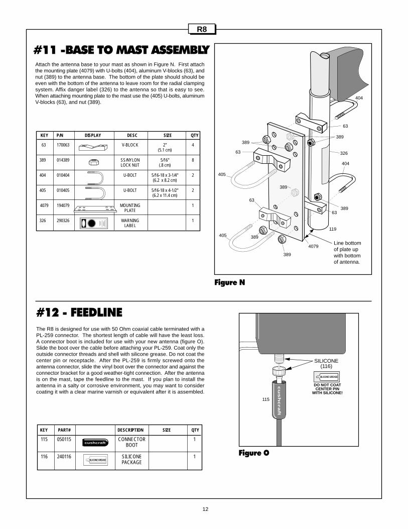
#11 -BASE TO MAST ASSEMBLY
KEY P/N DISPLAY DESC SIZE QTY
63 170063 V-BLOCK 2" 4(5.1 cm)
389 014389 SS/NYLON 5/16" 8LOCK NUT (.8 cm)
404 010404 U-BOLT 5/16-18 x 3-1/4" 2(6.2 x 8.2 cm)
405 010405 U-BOLT 5/16-18 x 4-1/2" 2(6.2 x 11.4 cm)
4079 194079 MOUNTING 1PLATE
326 290326 WARNING 1LABEL
389
405
404
405
389
119
389
389
63
63
63
63
389
389
4079
326
Attach the antenna base to your mast as shown in Figure N. First attachthe mounting plate (4079) with U-bolts (404), aluminum V-blocks (63), andnut (389) to the antenna base. The bottom of the plate should should beeven with the bottom of the antenna to leave room for the radial clampingsystem. Affix danger label (326) to the antenna so that is easy to see.When attaching mounting plate to the mast use the (405) U-bolts, aluminumV-blocks (63), and nut (389).
404
Line bottomof plate upwith bottomof antenna.
#12 - FEEDLINEThe R8 is designed for use with 50 Ohm coaxial cable terminated with aPL-259 connector. The shortest length of cable will have the least loss.A connector boot is included for use with your new antenna (figure O).Slide the boot over the cable before attaching your PL-259. Coat only theoutside connector threads and shell with silicone grease. Do not coat thecenter pin or receptacle. After the PL-259 is firmly screwed onto theantenna connector, slide the vinyl boot over the connector and against theconnector bracket for a good weather-tight connection. After the antennais on the mast, tape the feedline to the mast. If you plan to install theantenna in a salty or corrosive environment, you may want to considercoating it with a clear marine varnish or equivalent after it is assembled.
KEY PART# DESCRIPTION SIZE QTY
115 050115 CONNECTOR 1BOOT
116 240116 SILICONE 1PACKAGE
SILICONE GREASE
cushcraft
115
SILICONE(116)
DO NOT COATCENTER PIN
WITH SILICONE!
SILICONE GREASE
cu
sh
cra
ft
R8

LIMITED WARRANTYCushcraft Corporation, 48 Perimeter Road, Manchester, New Hampshire 03103, warrants to the original purchaser for oneyear from date of purchase that each Cushcraft antenna is free of defects in material or workmanship. If, in the judgementof Cushcraft, any such antenna is defective, then Cushcraft Corporation will, at its option, repair or replace the antennaat its expense within thirty days of the date the antenna is returned (at purchasers expense) to Cushcraft or one of itsauthorized representatives. This warranty is in lieu of all other expressed warranties, any implied warranty is limited induration to one year. Cushcraft Corporation shall not be liable for any incidental or consequential damages which mayresult from a defect. Some states do not allow limitations on how long an implied warranty lasts or exclusions or limitationsof incidental or consequential damages, so the above limitation and exclusion may not apply to you. This warranty givesyou specific legal rights, and you may also have other rights which vary from state to state. This warranty does not extendto any products which have been subject the misuse, neglect, accident or improper installation. Any repairs or alterationsoutside of the Cushcraft factory will nullify this warranty.
48 PERIMETER ROAD, MANCHESTER, NH 03103 USATELEPHONE: 603-627-7877 • FAX: 603-627-1764 • E-mail: [email protected]
SPECIFICATIONS SUBJECT TO CHANGE WITHOUT NOTICE
The Electrical Specifications for all Cushcraft Amateur Antennas are derived from numericalanalysis and measured data taken on our test range. Performance may vary due to the randomvariables associated with a specific application or installation.
Frequency, meters 6,10,12,15,17,20,30,40Gain, dBi 3 VSWR 2:1 bandwidth, KHz 40m (150)
30m (>50) 20m (>350) 17m (>100) 15m (>450) 12m (>100) 10m (>1500) 6m (>1500)VSWR at resonance (typical) 1.3:1Power Rating, Watts CW 1500Vertical Radiation angle, deg. 16Horizontal rad, deg. 360Height, ft(m) 28.5 max. (8.7)Wind survival 80 mphWeight, lb. (kg) 23 (10.5)
R8 SPECIFICATIONS