ASSA ABLOY · Notes: • All dimensions are given in inches. • Thickness recommended for...
24
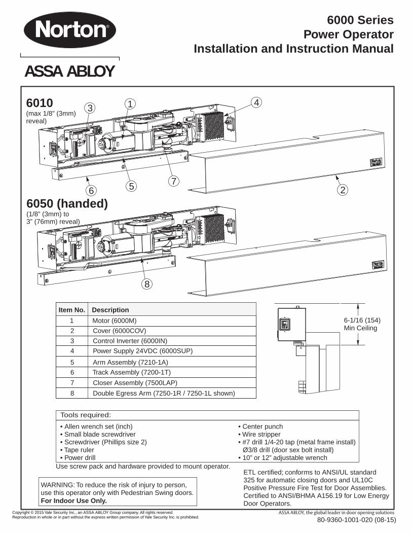
6000 Series Power Operator Installation and Instruction Manual • Allen wrench set (inch) • Center punch • Small blade screwdriver • Wire stripper • Screwdriver (Phillips size 2) • #7 drill 1/4-20 tap (metal frame install) • Tape ruler Ø3/8 drill (door sex bolt install) • Power drill • 10” or 12” adjustable wrench Tools required: Use screw pack and hardware provided to mount operator. ETL certified; conforms to ANSI/UL standard 325 for automatic closing doors and UL10C Positive Pressure Fire Test for Door Assemblies. Certified to ANSI/BHMA A156.19 for Low Energy Door Operators. WARNING: To reduce the risk of injury to person, use this operator only with Pedestrian Swing doors. For Indoor Use Only. Item No. Description 1 Motor (6000M) 2 Cover (6000COV) 3 Control Inverter (6000IN) 4 Power Supply 24VDC (6000SUP) 5 Arm Assembly (7210-1A) 6 Track Assembly (7200-1T) 6010 (max 1/8” (3mm) reveal) 6050 (handed) (1/8” (3mm) to 3” (76mm) reveal) 4 7 5 6 2 1 3 8 7 Closer Assembly (7500LAP) 8 Double Egress Arm (7250-1R / 7250-1L shown) 6-1/16 (154) Min Ceiling ASSA ABLOY Copyright © 2015 Yale Security Inc., an ASSA ABLOY Group company. All rights reserved. Reproduction in whole or in part without the express written permission of Yale Security Inc. is prohibited. 80-9360-1001-020 (08-15)
Transcript of ASSA ABLOY · Notes: • All dimensions are given in inches. • Thickness recommended for...
6000 SeriesPower Operator
Installation and Instruction Manual
bull Allen wrench set (inch) bull Center punchbull Small blade screwdriver bull Wire stripperbull Screwdriver (Phillips size 2) bull 7 drill 14-20 tap (metal frame install)
bull Tape ruler Oslash38 drill (door sex bolt install)bull Power drill bull 10rdquo or 12rdquo adjustable wrench
Tools required
Use screw pack and hardware provided to mount operator ETL certified conforms to ANSIUL standard325 for automatic closing doors and UL10CPositive Pressure Fire Test for Door AssembliesCertified to ANSIBHMA A15619 for Low EnergyDoor Operators
WARNING To reduce the risk of injury to person use this operator only with Pedestrian Swing doorsFor Indoor Use Only
Item No Description
1 Motor (6000M)
2 Cover (6000COV)
3 Control Inverter (6000IN)
4 Power Supply 24VDC (6000SUP)
5 Arm Assembly (7210-1A)
6 Track Assembly (7200-1T)
6010(max 18rdquo (3mm) reveal)
6050 (handed)(18rdquo (3mm) to 3rdquo (76mm) reveal)
4
756 2
13
8
7 Closer Assembly (7500LAP)
8 Double Egress Arm (7250-1R 7250-1L shown)
6-116 (154)Min Ceiling
ASSA ABLOY
Copyright copy 2015 Yale Security Inc an ASSA ABLOY Group company All rights reserved Reproduction in whole or in part without the express written permission of Yale Security Inc is prohibited 80-9360-1001-020 (08-15)
For assistance contact Norton Technical Product Support at 800-438-1951 Ext 4706
3000 Highway 74 East bull Monroe NC 28112Tel 800-438-1951 Ext 4706 bull Fax 800-338-0965
wwwnor tondoorcontrolscom
ASSA ABLOY
General Information
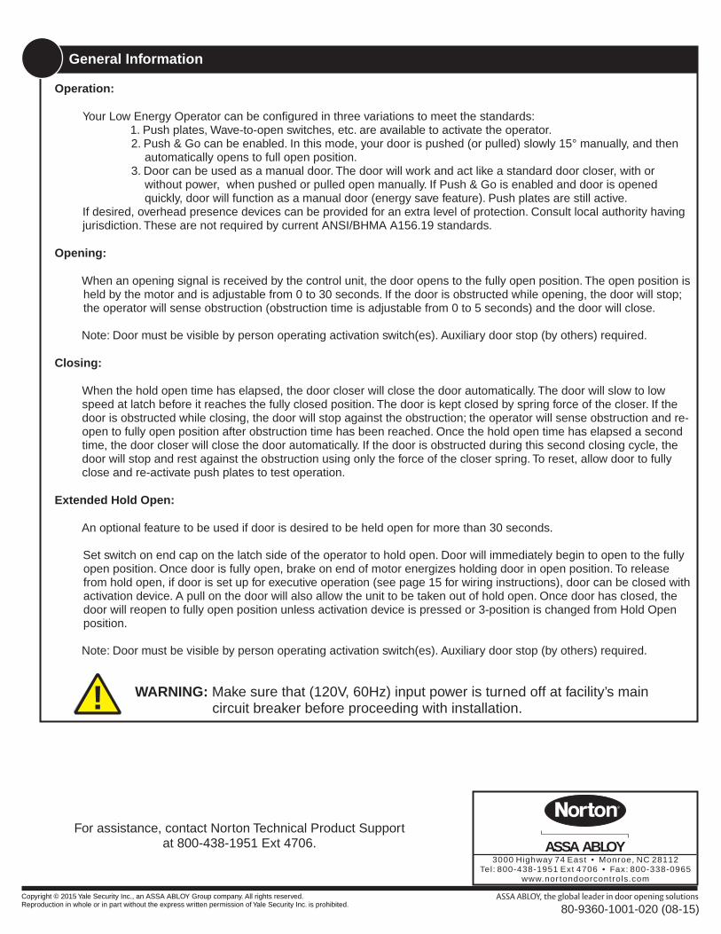
WARNING Make sure that (120V 60Hz) input power is turned off at facilityrsquos main circuit breaker before proceeding with installation
Operation
Your Low Energy Operator can be configured in three variations to meet the standards1 Push plates Wave-to-open switches etc are available to activate the operator 2 Push amp Go can be enabled In this mode your door is pushed (or pulled) slowly 15deg manually and then
automatically opens to full open position 3 Door can be used as a manual door The door will work and act like a standard door closer with or
without power when pushed or pulled open manually If Push amp Go is enabled and door is opened quickly door will function as a manual door (energy save feature) Push plates are still active
If desired overhead presence devices can be provided for an extra level of protection Consult local authority having jurisdiction These are not required by current ANSIBHMA A15619 standards
Opening
When an opening signal is received by the control unit the door opens to the fully open position The open position is held by the motor and is adjustable from 0 to 30 seconds If the door is obstructed while opening the door will stop the operator will sense obstruction (obstruction time is adjustable from 0 to 5 seconds) and the door will close
Closing
When the hold open time has elapsed the door closer will close the door automatically The door will slow to low speed at latch before it reaches the fully closed position The door is kept closed by spring force of the closer If the door is obstructed while closing the door will stop against the obstruction the operator will sense obstruction and re-open to fully open position after obstruction time has been reached Once the hold open time has elapsed a second time the door closer will close the door automatically If the door is obstructed during this second closing cycle the door will stop and rest against the obstruction using only the force of the closer spring To reset allow door to fully close and re-activate push plates to test operation
Note Door must be visible by person operating activation switch(es) Auxiliary door stop (by others) required
Extended Hold Open
An optional feature to be used if door is desired to be held open for more than 30 seconds
Set switch on end cap on the latch side of the operator to hold open Door will immediately begin to open to the fully open position Once door is fully open brake on end of motor energizes holding door in open position To release from hold open if door is set up for executive operation (see page 15 for wiring instructions) door can be closed with activation device A pull on the door will also allow the unit to be taken out of hold open Once door has closed the door will reopen to fully open position unless activation device is pressed or 3-position is changed from Hold Open position
Note Door must be visible by person operating activation switch(es) Auxiliary door stop (by others) required
Copyright copy 2015 Yale Security Inc an ASSA ABLOY Group company All rights reserved Reproduction in whole or in part without the express written permission of Yale Security Inc is prohibited 80-9360-1001-020 (08-15)
Notesbull All dimensions are given in inchesbull Thickness recommended for reinforcements in hollow metal doors and frames is charted at the left of this page
bull Do not scale drawingbull This template information based upon use of 5 maximum width butt hinges
bull Maximum frame reveal is 18 for 6010 units and 18rdquo up to 3rdquo maximum for 6050 units
bull Before beginning the installation verify that the door frame is properly reinforced and is well anchored in the wall
bull Unreinforced hollow metal frames and aluminum frames should be prepared and fitted with 14-20 blind rivet nuts furnished by others
bull Concealed electrical conduit and concealed switch or sensor wires should be pulled to the frame before proceeding
Hollow Metal Door Frame Reinforcing
FrameMaterial
12 Ga1046(266)
14 Ga0747(190)
16 Ga0598(152)
18 Ga0478(121)
12 Ga1046(266)
10 Ga1343(341)
10 Ga1343(341)
8 Ga1644(418)
18 Ga0478(121)
12 Ga1046(266)
12 Ga1046(266)
10 Ga1343(341)
ReinforcingRecommended Min Required
18(3)
Door
Frame
Templating is based on 18 gap between door and frame
Fasteners for Frame14-20 Machine screws for hollow metal and aluminumNo 14x2-34 ldquo (70mm) long sheet metal screws for wood
bull
bull
Door Prep
Technical Data
Notes Permanent wiring is to be employed as required by local codesActivation devices push plates access control mats touchless wall switches etc
Maximum wire size is12AWG at terminals LINE and NEUTRAL (120VAC 60Hz) on Power Input Terminal mounted on inside of end cap14AWG at all other terminals
120VAC 60Hz
9 amps
24 V DC max 22 Amp28 - 48 (71-122 cm)
100-250 lb (45-113 kg)
Input power
Power consumption
Power supply
Door width
Door weightDoor opening angle
up to 110deg with reveal up to 3rdquo (76 cm) max
Hold open time 0-30 seconds (ADA 5 seconds min)Indefinite for optional Extended Hold Open
3 ampsCircuit breaker
Page 3
Standards
ETL Certified conforms to ANSIUL standard 325 for automatic closing doors and UL10C
ANSI A15619These products are designed to conform to this specification ldquofor power assist and low energy power operated doorsrdquo These products are designed to exceed all the requirements for the ldquoLow Energy Power Operated Doorrdquo
Positive Pressure Fire Test for Door Assemblies
Americans with Disabilities Act (ADA)These door operators can be installed and adjusted to conform with ADA regulations
ANSI A1171These door controls permit door assemblies to conform to the requirements of this specification ldquofor buildings and facilities - providing accessibility and usability for physically handicapper peoplerdquo
Rate of operation shall not exceed 300 cycles of opening and closing per hour
ASSA ABLOY
Copyright copy 2015 Yale Security Inc an ASSA ABLOY Group company All rights reserved Reproduction in whole or in part without the express written permission of Yale Security Inc is prohibited 80-9360-1001-020 (08-15)
Initial Frame Holes1aLeft hand door illustrated
A Using template locate and prepare holes in the frame
B Drill 7 and tap 14-20 Machine Screws or Self Drilling Screws (2 places)
CLHinge
34rdquo
21-516rdquo
1-116rdquoSee page 20 for removable
template
Initial Wall Prep1b
Left hand door
illustrated
Blocking (supplied by others) is required for proper support of operator Thickness dependent upon Frame Return Material must comply with local codesA For wood framing screw blocking
into wall studsB Lag anchoring required for
masonry walls
5-58rdquo
Frame Return
CLHinge
3rdquo max
16-34rdquo min
IMPORTANT INSTALLATION INSTRUCTIONS
1) READ AND FOLLOW ALL INSTALLATION INSTRUCTIONS
2) Install only on a properly operating and balanced door A door that is operating improperly could cause severe injury Have qualified service personnel make repairs to any hardware before installing the operator
3) Remove or make inoperative all locks (unless mechanically andor electrically interlocked to the power unit) that are connected to the door before installing the operator
4) Do not connect the door operator to the source power until instructed to do so
Page 4
Unpack Operator1cA Remove from box and unwrap operatorB Remove (6) screws holding cover (save to
be reused later) and remove cover
C Carefully remove cardboard insertD Cut large cable tie remove (2) 14-20 hex
bolts and separate back plate and closer sub-assembly
Cable Tie
ASSA ABLOY
14-20 Hex Bolts
Copyright copy 2015 Yale Security Inc an ASSA ABLOY Group company All rights reserved Reproduction in whole or in part without the express written permission of Yale Security Inc is prohibited 80-9360-1001-020 (08-15)
Page 5
ASSA ABLOY
Back Plate Mounting2aA Install (2) 14-20 x 1rdquo screws
into holes drilled in Step 1A Leave 18rdquo gap between bottom of screw head and frame
B i) Install Back Plate assembly over screws in previous step and ii) slide Back Plate toward Latch edge of door
C Secure (2) screws
Note Level is incorporated into back plate to aid in installation
iii
iii
For Concealed Wiring Only2bA Mark conduit holes using back plate as
templateB Remove back plate
C Drill (2) Oslash78rdquo holesD Install conduit in frame if desiredE Reinstall back plate and secure (2) screws
Remaining Back Plate Screws3A
B Install (7) 14-20 x 1rdquo screws into holes drilled in Step 3A Leave 18rdquo gap between bottom of screw head of screws marked ldquoCloserrdquo and frame
C Support between back plate and wall is required (see Step 1b)
Drill 7 and tap 14-20 Machine Screws or Self Drilling Screws (7 places)
ldquoCloserrdquo Screws
See page 20 for removable
template
Concealed Wiring Holes
Copyright copy 2015 Yale Security Inc an ASSA ABLOY Group company All rights reserved Reproduction in whole or in part without the express written permission of Yale Security Inc is prohibited 80-9360-1001-020 (08-15)
Page 6
ASSA ABLOY
Assembly Closer Sub-Assembly4
A i) Install Closer Sub-Assembly over screws in Step 3 with closer spring tube under power supply and ii) slide Closer Sub-Assembly toward Hinge edge of door NOTE Valves on door closer should be pointing toward the chain
B Secure screws for Closer Sub-Assembly from Step 3C Secure top of Sub-Assembly to Blocking (for masonry
use anchors and spacers)D Connect wiring harnesses from Closer Sub-Assembly to
Back Plate Assembly Connectors are keyed and only connect in one direction Connectors will lock
i
ii
i
iiFrom CloserSub-Assembly From Back
Plate Assembly
Attach Wiring Harness to Chain Guard5Using Cable Tie supplied in pack with installation instructions secure wiring harness to loop on chain guard just above the pinion
Note Wiring to be routed so it does not interfere with pulley is out of door opening and must route beside chain guard not over at motor area for cover to fit properly
Cable Tie
Wiring Not ToInterfere with
Pulley
Wiring HarnessRoute AlongSide of Chain
Guard
Prep Door for Track6A Using template
locate and prepare holes in door
B Drill 38rdquo thru (3 places) for sex bolts CLHinge
5-38rdquo11rdquo
22rdquoDIM ldquoArdquoSee page 20
for removable template
Dim ldquoArdquo6010 1-316rdquo6050 1-1316rdquo
Copyright copy 2015 Yale Security Inc an ASSA ABLOY Group company All rights reserved Reproduction in whole or in part without the express written permission of Yale Security Inc is prohibited 80-9360-1001-020 (08-15)
Wiring Not ToInterfere with
Brake Assemblyon end of Motor
Mount Track on Door7A
B Install (3) 14-20 x 2rdquo screws thru track and into sex bolts installed in Step 6A
Note Opening of track is toward the top fo the door and the adjustable stop is toward the hinge edge of the door
Install sex bolts thru holes in back side of door (3 places) prepared in Step 5
Sex Bolts
Secure Arm to Pinion9A Attach arm with
provided screw and washer
B Tighten arm screw with 716rdquo wrench
Assemble Arm to Pinion8Mount closer arm to pinion square
as shown
RE-INSTALLHERE LEFT
HANDRIGHTHAND
Align the pinion flat asshown
All views from floor looking upward
A Use adjustable wrench to rotate pinion square on top side of unit approximately 45deg
B With arm parallel to frame as at right and pinion flats oriented as at right mount arm onto pinion square
PINIONFLAT
LEFTHAND
RIGHTHAND
Page 7
ASSA ABLOY
Copyright copy 2015 Yale Security Inc an ASSA ABLOY Group company All rights reserved Reproduction in whole or in part without the express written permission of Yale Security Inc is prohibited 80-9360-1001-020 (08-15)
Closer Spring Force Adjustment11Pull side closers are shipped with spring force at maximum adjustment Spring force can be lowered as required
NOTE A closer set to the ADA required 5 lbs opening force may not be strong enough to close the door due to latching hardware air pressure or frame issues -
+Stronger
Weaker
Mechanical Closer Adjustments12
Never Close
back check valve completely
Do not remove valves from closer Hydraulic
oil will escape
Closer Must function mechanically as a standard door closer before applying any power
Closing Speed Controlsbull Valve S Controls Sweep Range from full open to
5degbull Valve L Controls Latch Range from 5deg to closed
Opening Cyclebull B controls the strength of cushioning in Back check Range NEVER close this valve completely ndash it is not to provide a positive stopbull Valve P adjusts the angle that back check is felt in the open cycle
Valve
+
-
18HexKey
BBack check
75degWeaker
Stronger
18HexKey
PBack check
Position
75deg90deg
SSweep
5deg
18HexKey
wo el rS
Fa rste
LLatch
0deg
5deg
18HexKey
wo el rS
Fa rste
Note Valve location SD is not adjustable
Connect Arm To Track10A
AssemblyB Press clip on back side of
Slide Assembly onto Arm Stud
Insert Arm Stud into Slide
Slide Assembly
Arm Stud
B
A
Page 8
ASSA ABLOY
Copyright copy 2015 Yale Security Inc an ASSA ABLOY Group company All rights reserved Reproduction in whole or in part without the express written permission of Yale Security Inc is prohibited 80-9360-1001-020 (08-15)
Page 9
ASSA ABLOY
Track Stop Adjustment13A Use allen wrench to loosen set screw in Bumper StopB Open door to full open positionC Slide Bumper Stop until it just touches the end of the
sliderD Use allen wrench to tighten set screw in Bumper Stop
so bumper will stay in position
Set Screw
Bumper Stop
Incoming Power Connection14Low voltage Control Wiring
Incoming Power
Ground Screw (Green)
Low voltage Control WiringIncoming Power
SecureScrew
SurfaceMountedConduitShown
ConcealedConduitShown
D Secure wire into terminal by turning screw using a small flat blade screw driver
E Attach ground wire to green ground screw
A Pull wire thru Incoming Power conduitB Strip insulation back 38rdquo on Hot and
Common Incoming Power wiresC Insert stripped end of wire into terminal
Controller Interface15
LCD Screen
Joystick
See Page 12 for ControllerAdjustment Options
A To power unit flip switch on end cap furthest from the hinge from ldquoOFFrdquo to ldquoONrdquo position
B To scroll thru menu items push up or down on joystickC To change setting of a menu item when cursor is on that
item push joystick right to increase or left to decrease valueD To permanently accept changes to settings scroll down to
ldquoSave Valuesrdquo and press in on the joystick NOTE If power is turned off to the unit before ldquoSave Valuesrdquo has been accepted to ldquoSavedrdquo any changes made to that point will be lost
Copyright copy 2015 Yale Security Inc an ASSA ABLOY Group company All rights reserved Reproduction in whole or in part without the express written permission of Yale Security Inc is prohibited 80-9360-1001-020 (08-15)
InsertWire
Signal(Dry)
Contacts
24VDCPower
Outputs
120VACPowerInputs
Line Neutral
Connect Accessories and Make Necessary Controller Adjustments17
Install Cover and Label18
See Page 12 for Controller AdjustmentsSee Pages 13 - 19 for Accessory Wiring Instructions
See Page 20 for Troubleshooting Guide
Cover surfacefacing ceiling
2-781-58
78
Clearance forStrain Relief
frac12
frac12
Left HandDoor
Right HandDoor
A If using Surface Mount power input ONLY remove appropriate shaded area from cover see illustration below Repaint cut edges as necessary to prevent corrosion
B Place cover over unit and secure with (6) 6-32 screws taken out previously
C Attach label to cover as shown at right
Page 10
ASSA ABLOY
Set Home and Open Positions16A With door closed and 3-position switch on end
of back plate in the ldquoOFFrdquo position use joystick to scroll down menu on LCD screen to ldquoHomerdquo
B Push in on joystick to activate menu feature Display changes to ldquoSet Close Limitrdquo
C Push in on joystick again while door is still closed to set the Home or closed position Display changes to ldquoSet Open Limitrdquo
D Open door to desired open position and push in on joystick again Display changes to ldquoClosing to Homerdquo
E Allow door to fully close again Display changes to ldquoHomerdquo
F Scroll to Save Values and push in on joystick to permanently save open and closed positions
E)
D)
C)
B)A) Hom
e
Copyright copy 2015 Yale Security Inc an ASSA ABLOY Group company All rights reserved Reproduction in whole or in part without the express written permission of Yale Security Inc is prohibited 80-9360-1001-020 (08-15)
Controller Error Codes
Error Code DescriptionShort Circuit A short was sensed on the motor outputs
Temperature TripPower module reached 200degF or greater (too much load in too hot ambient condition)
Over Voltage Line Voltage has reached 145VAC or greaterUnder Voltage Line Voltage has dropped below 80VACAux 1 Stuck Activation device connected to Aux 1 is sending constant signalAux 2 Stuck Activation device connected to Aux 2 is sending constant signalAux 3 Stuck Activation device connected to Aux 3 is sending constant signal
Comm ErrorNo communication between top and bottom controller boards Boards not functioning properly
Presense Detect Device connected to Presence Detect and was activatedDrive Disabled 3-position switch on end cap closest to latch is in OFF position
Page 11
ASSA ABLOY
General Electrical Information
PowerOn OffSwitch
CircuitBreaker
PoweredOutputContacts
AuxiliaryDryContacts
PowerInput andBasic AuxConnection
A Power inputs at Power Input Connection and Power Output Contacts must be made with copper wire only
B Maximum wire size 12 AWG at Power Input connection 14 AWG at all other terminalsC Power input at terminals LINE and NEUTRAL
must be 120VAC at 60 Hz (+10 -15)D Maximum current draw from auxiliary devices
is 13 ampsE All wiring and connections use standard
wiring practice conforming with local wiring codes
F Labeled fire or smoke barrier door assemblies require the 120VAC 60Hz power input be supplied through normally closed alarm contacts of the alarm system alarm panel
IMPORTANT SAFETY INSTRUCTIONS - WARNING To reduce the risk of severe injury or death
1) READ AND FOLLOW ALL INSTRUCTIONS2) Never let children operate or play with door
controls Keep the remote control (where provided) away from children
3) Personnel should keep away from a moving door in motion
4) Test the doorrsquos safety features at least once a month After adjusting either the force or the limit of travel retest the door operatorrsquos safety features
Failure to adjust the operator properly may cause severe injury or death
5) KEEP DOOR PROPERLY OPERATING See Door Manufacturerrsquos Ownerrsquos Manual An improperly operating door could cause severe injury or death Have a trained door systems technician make repairs
6) SAVE THESE INSTRUCTIONS
Copyright copy 2015 Yale Security Inc an ASSA ABLOY Group company All rights reserved Reproduction in whole or in part without the express written permission of Yale Security Inc is prohibited 80-9360-1001-020 (08-15)
Page 12
ASSA ABLOY
Controller Interface Description
Screen Display Adjustments Default DescriptionMount Push or Pull Pull Side of opening operator is mounted on
Push OFF or PushNGo OffTurn on or off Push N Go featureIf On a slight push or pull of the door starts it automatically opening
Obst Delay 0 - 5 sec in 1 sec increments 3s
Obstruction Delay the amount of time the operator will push against an obstruction before closing if during an opening cycle or reopening and trying to close again if during a closing cycle
Hold Open 0 - 30 sec in 1 sec increments 6s Amount of time door will stay in full open positionOpen Speed 0 - 100 in 1 increments 100 How fast the door opens to full open position
Close Speed 0 - 100 in 1 increments 60
How fast the motor returns to the home position As Latch and Sweep on the closer are adjusted adjustments may be needed for Close Speed to assure closer is not trying to backdrive the motor
Slow Speed 0 - 100 in 1 increments 55Speed up or slow down door during last few degrees of opening
Hold Speed 0 - 100 in 1 increments 55
Increase or decrease hold open force (when in ON position only not HO) to compensate for spring force wind conditions etc
Start Delay 0 - 10 sec in 1 sec increments 0s
Time before operator begins to open door This is to allow accessories time to function and not hinder the opening of the door
VestibuleOFF 5 - 30 in 5 sec increments Off Amount of delay for opening 2nd vestibule door
Latch RtrctOFF 3 - 45 in 3 sec increments Off Amount of time power is supplied to a latch retraction device
Alarm Delay OFF 30 sec 60 sec Off Used only for alarm accessories
A2Standard Presence Off Presence On Standard
A2 input can be used for Alarm Delay or Input for door mounted presence detector Presence Off - door will not reactivate Presence On - door will reopen if presence detected during closing cycle
Rly2Alarm Activation On Opened On Closed Alarm
How Relay 2 is used Alarm - used with above Alarm Delay Activation - acts as an additional NO NC contact On Opened - relay trips (closed contacts) when door is in opened position On Closed - relay trips (closed contacts) when door reaches the fully closed position
Cycles not adjustable - Number of electrical cycles on the operator
Days not adjustable -Number of full days electricity have been supplied to the operator
Open Time not adjustable -Time it took for previous opening cycle to go from Home to fully open position
Close Time not adjustable -Time it took for previous closing cycle to go from fully open position to Home
Errors not adjustable -Error code seen by controller See below for Troubleshooting codes
Home see Setting Open Position -Used to set the Home position and the Fully Open positions of the operator
Save Values Save Values or Saved - Used to permanently add adjustments to controllers memory
Copyright copy 2015 Yale Security Inc an ASSA ABLOY Group company All rights reserved Reproduction in whole or in part without the express written permission of Yale Security Inc is prohibited 80-9360-1001-020 (08-15)
Factory Pre-Wiring of Connections
Basic Wiring Diagrams Using Factory Pre-Wired Connection
Standard Function with SwitchesŸ Doors are normally
closedŸ Activating either switch
will open both doors Door will close after hold open time delay has expired
Wall Switch Card Reader Key Switch etc(Normally Open Momentary dry contacts)
Wall Switch Card Reader Key Switch etc(Normally Open Momentary dry contacts)
-
24VDC Electric Strike (Fail Secure)
Wall Switch Card Reader Key Switch etc(Normally Open Momentary dry contacts)
+
Fail Secure Electric Strike 24VDC WiringŸ Doors are normally closed and
latchedŸ Activating switch will unlock
electric strike and door will automatically open Door will close after hold open time delay has expired
Ÿ The door will remain locked during power failure
GN
D+24N
CC
omN
ON
CC
omN
O
Aux1GNDPres DetGNDAux2GNDDoor ToggleGNDAux1Aux3GNDAux2No ConnBlow Open
Sig
nal
(Dry
)C
on
tact
s
24V
DC
Po
wer
Ou
tpu
ts
120V
AC
Po
wer
Inp
uts
Lin
e N
eutr
al
+-
+-
Sig
nal
(Dry)
Co
ntacts
24VD
CP
ow
erO
utp
uts
120VAC
Po
wer
Inp
uts
Lin
e Neu
tral
+-
+-
Sig
nal
(Dry
)C
on
tact
s
24V
DC
Po
wer
Ou
tpu
ts
120V
AC
Po
wer
Inp
uts
Lin
e N
eutr
al
+-
+-
Page 13
ASSA ABLOY
Copyright copy 2015 Yale Security Inc an ASSA ABLOY Group company All rights reserved Reproduction in whole or in part without the express written permission of Yale Security Inc is prohibited 80-9360-1001-020 (08-15)
Signal(Dry)
Contacts
24VDCPower
Outputs
120VACPowerInputs
Line Neutral
Fail Safe Electric Strike or Electromagnetic Lock 24VDC Wiring
Change Factory Pre-Wiring from Illustration A to Illustration B (more NO to NC)
A) B)
-
24VDC Electric Strike (Fail Secure)
Wall Switch Card Reader Key Switch etc(Normally Open Momentary dry contacts)
+
Fail Safe Electric Strike 24VDC WiringŸ Doors are normally closed and
latchedŸ Activating switch will unlock
electric strike or mag lock and door will automatically open Door will close after hold open time delay has expired
Ÿ The door will remain unlocked during power failure
Ÿ Current draw at Power Outputs not to exceed 13 amps
24VDC Electric Exit Device Wiring
Factory Pre-Wiring in Illustration is for this functionality
24VDC Electromagnetic Lock (Fail Safe)
Wall Switch Card Reader Key Switch etc(Normally Open Momentary dry contacts)
24VDC Electric Exit Device WiringŸ Doors are normally closed and
latchedŸ Activating switch will energize exit
device and door will automatically open Exit device will stay energized based on Latch Rtrct setting Door will close after hold open time delay has expired
Ÿ Current draw at Power Outputs not to exceed 13 amps
-+
GN
D+24N
CC
omN
ON
CC
omN
O GN
D+24N
CC
omN
ON
CC
omN
O
GN
D+24N
CC
omN
ON
CC
omN
O
Sig
nal
(Dry
)C
on
tact
s
24V
DC
Po
wer
Ou
tpu
ts
120V
AC
Po
wer
Inp
uts
Lin
e N
eutr
al
+-
+-
Sig
nal
(Dry
)C
on
tact
s
24V
DC
Po
wer
Ou
tpu
ts
120V
AC
Po
wer
Inp
uts
Lin
e N
eutr
al
+-
+-
-+
24VDC Electric Exit Device
Page 14
ASSA ABLOY
Copyright copy 2015 Yale Security Inc an ASSA ABLOY Group company All rights reserved Reproduction in whole or in part without the express written permission of Yale Security Inc is prohibited 80-9360-1001-020 (08-15)
Electric Latch Retraction Exit Device Wiring
Change Factory Pre-Wiring from Illustration A to Illustration B
A) B)
Electric Latch Retraction Exit Device WiringŸ Doors are normally closed and latchedŸ Activating switch will retract exit device
latch bolt and operator will open the doorŸ The door will closer after hold open time
delay has elapsedŸ Exit device allows egress at all times Exit
device allows egress during power failureŸ Contact Tech Support for other devices or
manufacturerrsquos instructions
Electric Latch Retraction Exit Device Wiring for Smoke Ventilation - Blow Open Function
Change Factory Pre-Wiring from Illustration A to Illustration B
A) B)
Electric Latch Retraction Exit Device Wiring - Blow OpenŸ Doors are normally closed and
latchedŸ Fire Alarm activation will retract exit
device latch bolt and door operator will open door
Ÿ Door will remain open until the Fire Alarm System has been reset
Ÿ Door Operatorrsquos main power input must be wired into buildingrsquos back-up power system
Ÿ Exit device allows egress at all times Exit device allows egress during power failure
Wall Switch Card Reader Key Switch etc(Normally Open Momentary dry contacts)
Latch Retraction Exit Device+-
120 VAC
Yale and Corbin Russwin shown
Fire Alarm System(Dry Contacts Only) C NO
7 8
1516 Latch Retraction Exit Device
+-
120 VAC
Yale and Corbin Russwin shown
NOTE This application must be approved by local (AHJ) authority
having jurisdiction
GN
D+24N
CC
omN
ON
CC
omN
O
GN
D+24N
CC
omN
ON
CC
omN
O
GN
D+24N
CC
omN
ON
CC
omN
O
Aux1GNDPres DetGNDAux2GNDDoor ToggleGNDAux1Aux3GNDAux2No ConnBlow Open
GN
D+24N
CC
omN
ON
CC
omN
O
Sig
nal
(Dry
)C
on
tact
s
24V
DC
Po
wer
Ou
tpu
ts
120V
AC
Po
wer
Inp
uts
Lin
e N
eutr
al
+-
+-
Sig
nal
(Dry
)C
on
tact
s
24V
DC
Po
wer
Ou
tpu
ts
120V
AC
Po
wer
Inp
uts
Lin
e N
eutr
al
+-
+-
Controller -782 (Yale)
782
7 8
1516
Controller - 782 (Yale)
782
Page 16
ASSA ABLOY
Copyright copy 2015 Yale Security Inc an ASSA ABLOY Group company All rights reserved Reproduction in whole or in part without the express written permission of Yale Security Inc is prohibited 80-9360-1001-020 (08-15)
Electric Dogging Exit Device Wiring
Change Factory Pre-Wiring from Illustration A to Illustration B (more NO to NC)
A) B)
Electric Dogging Exit Device WiringŸ Doors are normally closed and latchedŸ Turning key switch ON will apply power to
the exit deviceŸ The first depression on the device
touchpad will electrically dog the device for pushpull operation
Ÿ The door will now open automatically when the wall switch is depressed
Ÿ The device will relatch during a power failure or when the key switch is turned off
Ÿ The exit device allows egress at all times The exit device allows egress during power failures
Ÿ Current draw at Power Outputs not to exceed 13 amps
-
Wall Switch Card Reader Key Switch etc
(Normally Open Momentary dry contacts)
+ Touch Bar Monitor Switch
ON OFFKey Switch
24VDC Electric Dogging ExitDevice w Touch Bar Monitoring
(Yale and Corbin Russwin shown)
Hard Wired Executive Function Wiring
Wall Switch Card Reader Key Switch etc(Normally Open Momentary dry contacts)
Hard Wire Executive FunctionŸ Doors are normally closedŸ Activating switch will open doorŸ The door will remain in
indefinite hold open until activating switch or is activated a second time causing the door to close
Change Factory Pre-Wiring from Illustration A to Illustration B
A) B)
GN
D+24N
CC
omN
ON
CC
omN
O
Aux1GNDPres DetGNDAux2GNDDoor ToggleGNDAux1Aux3GNDAux2No ConnBlow Open
GN
D+24N
CC
omN
ON
CC
omN
O
GN
D+24N
CC
omN
ON
CC
omN
O GN
D+24N
CC
omN
ON
CC
omN
O
Sig
nal
(Dry
)C
on
tact
s
24V
DC
Po
wer
Ou
tpu
ts
120V
AC
Po
wer
Inp
uts
Lin
e N
eutr
al
+-
+-
Sig
nal
(Dry
)C
on
tact
s
24V
DC
Po
wer
Ou
tpu
ts
120V
AC
Po
wer
Inp
uts
Lin
e N
eutr
al
+-
+-
Page 15
ASSA ABLOY
Copyright copy 2015 Yale Security Inc an ASSA ABLOY Group company All rights reserved Reproduction in whole or in part without the express written permission of Yale Security Inc is prohibited 80-9360-1001-020 (08-15)
Radio Frequency Standard Function Wiring (can be ordered pre-wired to this RF wiring)
If installing in the field change Factory Pre-Wiring from Illustration A to Illustration B
A) B)
Radio Frequency Standard FunctionŸ Doors are normally closedŸ Activating wireless switch or hand
held wireless transmitter will open the door
Ÿ The door will closer after hold open time delay has elapsed
Ÿ Current draw at Power Outputs not to exceed 13 amps
Radio Frequency Executive Function Wiring
Change Factory Pre-Wiring from Illustration A to Illustration B
A) B)
Radio Frequency Executive FunctionŸ Doors are normally closed and
latchedŸ Activating wireless switch or hand
held wireless transmitter will open the door
Ÿ The door will remain in indefinite hold open until wireless switch or hand held transmitter is activated a second time causing the door to close
Ÿ Current draw at Power Outputs not to exceed 13 amps
12-2
4 V
AC
DC
CO
MN
ON
C
Optional secondLow Energy
Power Operator
If installing RF in the field attach receiver to bracket as shown with Velcro strips supplied
12-2
4 V
AC
DC
CO
MN
ON
C
Optional secondLow Energy
Power Operator
If installing RF in the field attach receiver to bracket as shown with Velcro strips supplied
GN
D+24N
CC
omN
ON
CC
omN
O
Aux1GNDPres DetGNDAux2GNDDoor ToggleGNDAux1Aux3GNDAux2No ConnBlow Open
GN
D+24N
CC
omN
ON
CC
omN
O
Sig
nal
(Dry
)C
on
tact
s
24V
DC
Po
wer
Ou
tpu
ts
120V
AC
Po
wer
Inp
uts
Lin
e N
eutr
al
+-
+-
Signal(Dry)
Contacts
24VDCPower
Outputs
120VACPowerInputs
Line Neutral
+-+-
Sig
nal
(Dry
)C
on
tact
s
24V
DC
Po
wer
Ou
tpu
ts
120V
AC
Po
wer
Inp
uts
Lin
e N
eutr
al
+-
+-
Signal(Dry)
Contacts
24VDCPower
Outputs
120VACPowerInputs
Line Neutral
+-+-
GN
D+24N
CC
omN
ON
CC
omN
O
GN
D+24N
CC
omN
ON
CC
omN
O
Page 17
ASSA ABLOY
Copyright copy 2015 Yale Security Inc an ASSA ABLOY Group company All rights reserved Reproduction in whole or in part without the express written permission of Yale Security Inc is prohibited 80-9360-1001-020 (08-15)
Page 18
ASSA ABLOY
Copyright copy 2015 Yale Security Inc an ASSA ABLOY Group company All rights reserved Reproduction in whole or in part without the express written permission of Yale Security Inc is prohibited 80-9360-1001-020 (08-15)
This PageLeft Blank
Vestibule Function WiringG
ND
+24N
CC
omN
ON
CC
omN
O
Aux1GNDPres DetGNDAux2GNDDoor ToggleGNDAux1Aux3GNDAux2No ConnBlow Open
GN
D+24N
CC
omN
ON
CC
omN
O
Aux1GNDPres DetGNDAux2GNDDoor ToggleGNDAux1Aux3GNDAux2No ConnBlow Open
Wall Switch Card Reader Key Switch etc(Normally Open Momentary dry contacts)
Wall Switch Card Reader Key Switch etc(Normally Open Momentary dry contacts)
Wall Switch Card Reader Key Switch etc(Normally Open Momentary dry contacts)
Wall Switch Card Reader Key Switch etc(Normally Open Momentary dry contacts)
Using Factory Pre-Wiring
Vestibule Function WiringŸ Doors are normally closed and latchedŸ Activating outside door switch will open the outside door
After the vestibule time delay has elapsed a signal will be sent to the inside door which will open Activating the inside door switch will open the inside door After the vestibule time delay has elapsed a signal will be sent to the outside door which will open Both doors will close when the hold open time delay has elapsed
Ÿ Activating the optional inside door switch located within the corridor will open the inside door only This door will re-close after the hold open delay has elapsed
Ÿ Activating the optional outside door switch located within the corridor will open the outside door only This door will re-close after the hold open delay has elapsed
INSIDE DOOR
OUTSIDE DOOR
Inside Switch
Optional InsideCorridor Switch
Outside Switch
Optional OutsideCorridor Switch
Page 19
ASSA ABLOY
Copyright copy 2015 Yale Security Inc an ASSA ABLOY Group company All rights reserved Reproduction in whole or in part without the express written permission of Yale Security Inc is prohibited 80-9360-1001-020 (08-15)
Troubleshooting Guide
Issue Seen Solution
Door closing too fast1) Adjust Latch andor Sweep valves on closer clockwise or 2) Decrease Closing Speed on controller (see page 10)
Door closing too slow1) Adjust Latch andor Sweep valves on closer counterclockwise or 2) Increase Closing Speed on controller (see page 10)
Door does not open to desired location
1) Repeat Home process (see page 8) 2) Increase Obst Delay 3) Adjust Backcheck valve on closer counterclockwise 4) Decrease spring force on closer body (door myst still close in event of power failure (see page 7) or 5) Move Bumper Stop in track slightly toward hinge (see page 7)
Door does not reach fully opened position
1) Repeat Home process (see page 9) 2) Increase Obst Delay 3) Adjust Backcheck valve on closer counterclockwise 4) Decrease spring force on closer body (door must still close in event of power failure (see page 7) or 5) Move Bumper Stop in track sligh
Door opens and closes repeatedly Change 3-position switch from HO to OnMotor is driving in the wrong direction
Change Mount (Push Pull) on controller reset Home process (see page 8) and Save Values
When door reaches open position door drifts toward closed position Increase Hold Speed on controller (see page 10) until door stops driftingWhen door reaches open position door drifts further open Decrease Hold Speed on controller (see page 10) until door stops driftingWhen door reaches open position door bounces Decrease Slow Speed on controller (see page 10)
When signal is received operator tries to open door before auxiliary components are unlatched retracted
1) Confirm latch devices are getting proper power 2) Confirm latch devices are receiving power long enough to fully retract - adjust Latch Retraction on controller (see page 10) as needed 3) If latch device is not retracting fast enough increase Start Delay on controller (see page 11) to assure latch device has had sufficient time to fully retract before operator starts opening door
Values previously set on controller are changed after power removed from operator
Reset necessary values on controller (see page 10) and Save Values Failure to Save Values will result in changes to the controller being lost when power is removed
Error message says Short Circuit Turn off power to unit Check wiring for short cutError message says Over Voltage Check incoming power - line voltage has exceeded 145VACError message says Under Voltage Check incoming power - line voltage has dropped below 80VAC
Error message says Aux1 Aux 2 or Aux 3 Stuck
Disconnect Aux 1 2 or 3 inputs and confirm error message goes away If so make sure input device is not stuck (sending contant signal) Controller has a 3 minute protection limit
Error message says Comm Error Inverter must be replacedError message says Presense Detect Unit has a presense detector attached and device has been activatedError message says Drive Disabled 3-position switch is in the Off position
Page 20
ASSA ABLOY
Copyright copy 2015 Yale Security Inc an ASSA ABLOY Group company All rights reserved Reproduction in whole or in part without the express written permission of Yale Security Inc is prohibited 80-9360-1001-020 (08-15)
TroubleshootingR4
Red LEDBlue LED
Antenna Wire
Learnwo DelayButton
DelayPotentiometer(Time Adjustment)
Learn wDelay Button
DIP Switch
TerminalStrip
Problem The LED on my receiver is just flickering and Irsquom unable to program andor it wonrsquot workSolution You have a push plate stuck or faulty transmitter Disconnect each push plate until the LED goes out If LED
does not go out remove each transmitter battery until it does Replace the appropriate transmitterProblem Receiver intermittently doesnrsquot receive the transmitter(s) signal
Solution You may extend the receiver antenna wire only in multiples of 6-34rdquo (171) ie 675 x 4 = 27rdquo (686) of extended antenna wire
Removing Transmitter Code(s) R3Single Transmitter Code
Ÿ Press both Delay and No Delay Buttons simultaneously until Red LED flashes once (approximately 1 second)Ÿ Press transmitter button twice within 10 seconds and the transmitter code will be deleted
All Transmitter CodesŸ Press and hold both Delay and No Delay Buttons simultaneously until Blue LED illuminates then release (approximately 10
seconds)
Push Plate Configuration R21 Before beginning it is easiest to have already prepared the installation of the push plate2 Connect the wires from the transmitter to the NO and COM contacts of the push platersquos switch3 Follow Steps 1 - 4 (Hand-Held Configuration) depress the push plate to activate the transmitter4 Attach the transmitter to the inside of the electrical box and complete the installation
Hand-Held Configuration R11 Set dip switches to the receiver to the desired activation cycle (dip switch 1 - Toggle or Pulse and dip switch 2 - 05s or 10s
hold2 Press either Learn w Delay Button or Learn wo Delay Button on the receiver depending on the activation requirements (if
delay learn is selected adjust potentiometer to counterclockwise limit 0 second delay) Red LED on receiver will flash After learn cycle is complete adjust potentiometer to desired delay time (0 - 30 sec)
3 Depress transmitter button repeatedly until Blue LED on the receiver illuminates (indicating reception of signal from transmitter)
NOTE Repeat Steps 2 - 3 to program additional transmitters4 To test the system depress transmitter button (Red LED on Transmitter will illuminate) and observe that the Blue LED
illuminates on the receiver This indicates that the relay has been activated
433MHz Receiver Userrsquos Guide
2OFFON
Description05s Hold Time10s Hold Time
FunctionRelay will remain active 05 sec after loss of activationRelay will remain active 10 sec after loss of activation
1OFF
ON
DescriptionPulse Relay
Toggle Relay
FunctionPress the transmitter once and the relay will be active momentarilyPress the transmitter once and the relay output is active indefinitely press it again and the relay will de-energize indefinitely
ON
1 2PU
L T
OG
05s
1
0s ON
1 2PU
L T
OG
05s
1
0sIn Toggle Setting (1-ON) the Hold Time is inactive Either setting for 2 dip switch will
have the same result
ON
1 2PU
L T
OG
05s
1
0s
05 second Pulse Setting
ON
1 2PU
L T
OG
05s
1
0s
10 second Pulse Setting
ŸAlways stop pedestrian traffic through the doorway when performing tests that may result in unexpected reactions by the door
ŸEnsure compliance with all applicable safety standards upon completion of installation
Page 21
ASSA ABLOY
Copyright copy 2015 Yale Security Inc an ASSA ABLOY Group company All rights reserved Reproduction in whole or in part without the express written permission of Yale Security Inc is prohibited 80-9360-1001-020 (08-15)
Page 22
ASSA ABLOY
This PageLeft Blank
Copyright copy 2015 Yale Security Inc an ASSA ABLOY Group company All rights reserved Reproduction in whole or in part without the express written permission of Yale Security Inc is prohibited 80-9360-1001-020 (08-15)
6010
6050
Removable TemplateŸ Do not scale drawingŸ Right hand door shownŸ All dimensions given in inches (mm)Ÿ Maximum frame reveal is 6-78rdquo (175 mm) for
this application
1-3
16(3
0)
1-1
4(3
2)
38
(10)
1-3
8(3
5)
11(2
79)
22(5
59)
frac12 (13)3
8(1
0)13
-14
(337
)
21-5
16
(541
)
30(7
62)
27-7
8(7
08)
1-1
16(2
7)
C LH
inge
or
Piv
ot1
4-20
Mac
hine
Scr
ews
or N
o 1
4 W
ood
Scr
ews
(7 P
lace
s)
78
(23)
For
Con
ceal
edW
ired
Uni
ts O
nly
(2 P
lace
s)3
8 D
ia
Sex
Nut
s(3
Pla
ces)
6-1
16U
nit H
eigh
t
Fram
eR
abbe
t
Fram
eS
top
Sof
fit
4(1
02)
58
(16)
Sto
p
34
(19)
5-3
8(1
37)
1-13
16
(46)
1-1
4(3
2)
38
(10)
1-3
8(3
5)
11(2
79)
22(5
59)
frac12 (13)3
8(1
0)13
-14
(337
)
21-5
16
(541
)
30(7
62)
27-7
8(7
08)
1-1
16(2
7)
C LH
inge
or
Piv
ot1
4-20
Mac
hine
Scr
ews
or N
o 1
4 W
ood
Scr
ews
(7 P
lace
s)
78
(23)
For
Con
ceal
edW
ired
Uni
ts O
nly
(2 P
lace
s)3
8 D
ia
Sex
Nut
s(3
Pla
ces)
6-1
16U
nit H
eigh
t
Fram
eR
abbe
t
Fram
eS
top
Sof
fit
4(1
02)
58
(16)
Sto
p
34
(19)
5-3
8(1
37)
Page 23
ASSA ABLOY
Copyright copy 2015 Yale Security Inc an ASSA ABLOY Group company All rights reserved Reproduction in whole or in part without the express written permission of Yale Security Inc is prohibited 80-9360-1001-020 (08-15)
Page 24
ASSA ABLOY
This PageLeft Blank
Copyright copy 2015 Yale Security Inc an ASSA ABLOY Group company All rights reserved Reproduction in whole or in part without the express written permission of Yale Security Inc is prohibited 80-9360-1001-020 (08-15)
For assistance contact Norton Technical Product Support at 800-438-1951 Ext 4706
3000 Highway 74 East bull Monroe NC 28112Tel 800-438-1951 Ext 4706 bull Fax 800-338-0965
wwwnor tondoorcontrolscom
ASSA ABLOY
General Information
WARNING Make sure that (120V 60Hz) input power is turned off at facilityrsquos main circuit breaker before proceeding with installation
Operation
Your Low Energy Operator can be configured in three variations to meet the standards1 Push plates Wave-to-open switches etc are available to activate the operator 2 Push amp Go can be enabled In this mode your door is pushed (or pulled) slowly 15deg manually and then
automatically opens to full open position 3 Door can be used as a manual door The door will work and act like a standard door closer with or
without power when pushed or pulled open manually If Push amp Go is enabled and door is opened quickly door will function as a manual door (energy save feature) Push plates are still active
If desired overhead presence devices can be provided for an extra level of protection Consult local authority having jurisdiction These are not required by current ANSIBHMA A15619 standards
Opening
When an opening signal is received by the control unit the door opens to the fully open position The open position is held by the motor and is adjustable from 0 to 30 seconds If the door is obstructed while opening the door will stop the operator will sense obstruction (obstruction time is adjustable from 0 to 5 seconds) and the door will close
Closing
When the hold open time has elapsed the door closer will close the door automatically The door will slow to low speed at latch before it reaches the fully closed position The door is kept closed by spring force of the closer If the door is obstructed while closing the door will stop against the obstruction the operator will sense obstruction and re-open to fully open position after obstruction time has been reached Once the hold open time has elapsed a second time the door closer will close the door automatically If the door is obstructed during this second closing cycle the door will stop and rest against the obstruction using only the force of the closer spring To reset allow door to fully close and re-activate push plates to test operation
Note Door must be visible by person operating activation switch(es) Auxiliary door stop (by others) required
Extended Hold Open
An optional feature to be used if door is desired to be held open for more than 30 seconds
Set switch on end cap on the latch side of the operator to hold open Door will immediately begin to open to the fully open position Once door is fully open brake on end of motor energizes holding door in open position To release from hold open if door is set up for executive operation (see page 15 for wiring instructions) door can be closed with activation device A pull on the door will also allow the unit to be taken out of hold open Once door has closed the door will reopen to fully open position unless activation device is pressed or 3-position is changed from Hold Open position
Note Door must be visible by person operating activation switch(es) Auxiliary door stop (by others) required
Copyright copy 2015 Yale Security Inc an ASSA ABLOY Group company All rights reserved Reproduction in whole or in part without the express written permission of Yale Security Inc is prohibited 80-9360-1001-020 (08-15)
Notesbull All dimensions are given in inchesbull Thickness recommended for reinforcements in hollow metal doors and frames is charted at the left of this page
bull Do not scale drawingbull This template information based upon use of 5 maximum width butt hinges
bull Maximum frame reveal is 18 for 6010 units and 18rdquo up to 3rdquo maximum for 6050 units
bull Before beginning the installation verify that the door frame is properly reinforced and is well anchored in the wall
bull Unreinforced hollow metal frames and aluminum frames should be prepared and fitted with 14-20 blind rivet nuts furnished by others
bull Concealed electrical conduit and concealed switch or sensor wires should be pulled to the frame before proceeding
Hollow Metal Door Frame Reinforcing
FrameMaterial
12 Ga1046(266)
14 Ga0747(190)
16 Ga0598(152)
18 Ga0478(121)
12 Ga1046(266)
10 Ga1343(341)
10 Ga1343(341)
8 Ga1644(418)
18 Ga0478(121)
12 Ga1046(266)
12 Ga1046(266)
10 Ga1343(341)
ReinforcingRecommended Min Required
18(3)
Door
Frame
Templating is based on 18 gap between door and frame
Fasteners for Frame14-20 Machine screws for hollow metal and aluminumNo 14x2-34 ldquo (70mm) long sheet metal screws for wood
bull
bull
Door Prep
Technical Data
Notes Permanent wiring is to be employed as required by local codesActivation devices push plates access control mats touchless wall switches etc
Maximum wire size is12AWG at terminals LINE and NEUTRAL (120VAC 60Hz) on Power Input Terminal mounted on inside of end cap14AWG at all other terminals
120VAC 60Hz
9 amps
24 V DC max 22 Amp28 - 48 (71-122 cm)
100-250 lb (45-113 kg)
Input power
Power consumption
Power supply
Door width
Door weightDoor opening angle
up to 110deg with reveal up to 3rdquo (76 cm) max
Hold open time 0-30 seconds (ADA 5 seconds min)Indefinite for optional Extended Hold Open
3 ampsCircuit breaker
Page 3
Standards
ETL Certified conforms to ANSIUL standard 325 for automatic closing doors and UL10C
ANSI A15619These products are designed to conform to this specification ldquofor power assist and low energy power operated doorsrdquo These products are designed to exceed all the requirements for the ldquoLow Energy Power Operated Doorrdquo
Positive Pressure Fire Test for Door Assemblies
Americans with Disabilities Act (ADA)These door operators can be installed and adjusted to conform with ADA regulations
ANSI A1171These door controls permit door assemblies to conform to the requirements of this specification ldquofor buildings and facilities - providing accessibility and usability for physically handicapper peoplerdquo
Rate of operation shall not exceed 300 cycles of opening and closing per hour
ASSA ABLOY
Copyright copy 2015 Yale Security Inc an ASSA ABLOY Group company All rights reserved Reproduction in whole or in part without the express written permission of Yale Security Inc is prohibited 80-9360-1001-020 (08-15)
Initial Frame Holes1aLeft hand door illustrated
A Using template locate and prepare holes in the frame
B Drill 7 and tap 14-20 Machine Screws or Self Drilling Screws (2 places)
CLHinge
34rdquo
21-516rdquo
1-116rdquoSee page 20 for removable
template
Initial Wall Prep1b
Left hand door
illustrated
Blocking (supplied by others) is required for proper support of operator Thickness dependent upon Frame Return Material must comply with local codesA For wood framing screw blocking
into wall studsB Lag anchoring required for
masonry walls
5-58rdquo
Frame Return
CLHinge
3rdquo max
16-34rdquo min
IMPORTANT INSTALLATION INSTRUCTIONS
1) READ AND FOLLOW ALL INSTALLATION INSTRUCTIONS
2) Install only on a properly operating and balanced door A door that is operating improperly could cause severe injury Have qualified service personnel make repairs to any hardware before installing the operator
3) Remove or make inoperative all locks (unless mechanically andor electrically interlocked to the power unit) that are connected to the door before installing the operator
4) Do not connect the door operator to the source power until instructed to do so
Page 4
Unpack Operator1cA Remove from box and unwrap operatorB Remove (6) screws holding cover (save to
be reused later) and remove cover
C Carefully remove cardboard insertD Cut large cable tie remove (2) 14-20 hex
bolts and separate back plate and closer sub-assembly
Cable Tie
ASSA ABLOY
14-20 Hex Bolts
Copyright copy 2015 Yale Security Inc an ASSA ABLOY Group company All rights reserved Reproduction in whole or in part without the express written permission of Yale Security Inc is prohibited 80-9360-1001-020 (08-15)
Page 5
ASSA ABLOY
Back Plate Mounting2aA Install (2) 14-20 x 1rdquo screws
into holes drilled in Step 1A Leave 18rdquo gap between bottom of screw head and frame
B i) Install Back Plate assembly over screws in previous step and ii) slide Back Plate toward Latch edge of door
C Secure (2) screws
Note Level is incorporated into back plate to aid in installation
iii
iii
For Concealed Wiring Only2bA Mark conduit holes using back plate as
templateB Remove back plate
C Drill (2) Oslash78rdquo holesD Install conduit in frame if desiredE Reinstall back plate and secure (2) screws
Remaining Back Plate Screws3A
B Install (7) 14-20 x 1rdquo screws into holes drilled in Step 3A Leave 18rdquo gap between bottom of screw head of screws marked ldquoCloserrdquo and frame
C Support between back plate and wall is required (see Step 1b)
Drill 7 and tap 14-20 Machine Screws or Self Drilling Screws (7 places)
ldquoCloserrdquo Screws
See page 20 for removable
template
Concealed Wiring Holes
Copyright copy 2015 Yale Security Inc an ASSA ABLOY Group company All rights reserved Reproduction in whole or in part without the express written permission of Yale Security Inc is prohibited 80-9360-1001-020 (08-15)
Page 6
ASSA ABLOY
Assembly Closer Sub-Assembly4
A i) Install Closer Sub-Assembly over screws in Step 3 with closer spring tube under power supply and ii) slide Closer Sub-Assembly toward Hinge edge of door NOTE Valves on door closer should be pointing toward the chain
B Secure screws for Closer Sub-Assembly from Step 3C Secure top of Sub-Assembly to Blocking (for masonry
use anchors and spacers)D Connect wiring harnesses from Closer Sub-Assembly to
Back Plate Assembly Connectors are keyed and only connect in one direction Connectors will lock
i
ii
i
iiFrom CloserSub-Assembly From Back
Plate Assembly
Attach Wiring Harness to Chain Guard5Using Cable Tie supplied in pack with installation instructions secure wiring harness to loop on chain guard just above the pinion
Note Wiring to be routed so it does not interfere with pulley is out of door opening and must route beside chain guard not over at motor area for cover to fit properly
Cable Tie
Wiring Not ToInterfere with
Pulley
Wiring HarnessRoute AlongSide of Chain
Guard
Prep Door for Track6A Using template
locate and prepare holes in door
B Drill 38rdquo thru (3 places) for sex bolts CLHinge
5-38rdquo11rdquo
22rdquoDIM ldquoArdquoSee page 20
for removable template
Dim ldquoArdquo6010 1-316rdquo6050 1-1316rdquo
Copyright copy 2015 Yale Security Inc an ASSA ABLOY Group company All rights reserved Reproduction in whole or in part without the express written permission of Yale Security Inc is prohibited 80-9360-1001-020 (08-15)
Wiring Not ToInterfere with
Brake Assemblyon end of Motor
Mount Track on Door7A
B Install (3) 14-20 x 2rdquo screws thru track and into sex bolts installed in Step 6A
Note Opening of track is toward the top fo the door and the adjustable stop is toward the hinge edge of the door
Install sex bolts thru holes in back side of door (3 places) prepared in Step 5
Sex Bolts
Secure Arm to Pinion9A Attach arm with
provided screw and washer
B Tighten arm screw with 716rdquo wrench
Assemble Arm to Pinion8Mount closer arm to pinion square
as shown
RE-INSTALLHERE LEFT
HANDRIGHTHAND
Align the pinion flat asshown
All views from floor looking upward
A Use adjustable wrench to rotate pinion square on top side of unit approximately 45deg
B With arm parallel to frame as at right and pinion flats oriented as at right mount arm onto pinion square
PINIONFLAT
LEFTHAND
RIGHTHAND
Page 7
ASSA ABLOY
Copyright copy 2015 Yale Security Inc an ASSA ABLOY Group company All rights reserved Reproduction in whole or in part without the express written permission of Yale Security Inc is prohibited 80-9360-1001-020 (08-15)
Closer Spring Force Adjustment11Pull side closers are shipped with spring force at maximum adjustment Spring force can be lowered as required
NOTE A closer set to the ADA required 5 lbs opening force may not be strong enough to close the door due to latching hardware air pressure or frame issues -
+Stronger
Weaker
Mechanical Closer Adjustments12
Never Close
back check valve completely
Do not remove valves from closer Hydraulic
oil will escape
Closer Must function mechanically as a standard door closer before applying any power
Closing Speed Controlsbull Valve S Controls Sweep Range from full open to
5degbull Valve L Controls Latch Range from 5deg to closed
Opening Cyclebull B controls the strength of cushioning in Back check Range NEVER close this valve completely ndash it is not to provide a positive stopbull Valve P adjusts the angle that back check is felt in the open cycle
Valve
+
-
18HexKey
BBack check
75degWeaker
Stronger
18HexKey
PBack check
Position
75deg90deg
SSweep
5deg
18HexKey
wo el rS
Fa rste
LLatch
0deg
5deg
18HexKey
wo el rS
Fa rste
Note Valve location SD is not adjustable
Connect Arm To Track10A
AssemblyB Press clip on back side of
Slide Assembly onto Arm Stud
Insert Arm Stud into Slide
Slide Assembly
Arm Stud
B
A
Page 8
ASSA ABLOY
Copyright copy 2015 Yale Security Inc an ASSA ABLOY Group company All rights reserved Reproduction in whole or in part without the express written permission of Yale Security Inc is prohibited 80-9360-1001-020 (08-15)
Page 9
ASSA ABLOY
Track Stop Adjustment13A Use allen wrench to loosen set screw in Bumper StopB Open door to full open positionC Slide Bumper Stop until it just touches the end of the
sliderD Use allen wrench to tighten set screw in Bumper Stop
so bumper will stay in position
Set Screw
Bumper Stop
Incoming Power Connection14Low voltage Control Wiring
Incoming Power
Ground Screw (Green)
Low voltage Control WiringIncoming Power
SecureScrew
SurfaceMountedConduitShown
ConcealedConduitShown
D Secure wire into terminal by turning screw using a small flat blade screw driver
E Attach ground wire to green ground screw
A Pull wire thru Incoming Power conduitB Strip insulation back 38rdquo on Hot and
Common Incoming Power wiresC Insert stripped end of wire into terminal
Controller Interface15
LCD Screen
Joystick
See Page 12 for ControllerAdjustment Options
A To power unit flip switch on end cap furthest from the hinge from ldquoOFFrdquo to ldquoONrdquo position
B To scroll thru menu items push up or down on joystickC To change setting of a menu item when cursor is on that
item push joystick right to increase or left to decrease valueD To permanently accept changes to settings scroll down to
ldquoSave Valuesrdquo and press in on the joystick NOTE If power is turned off to the unit before ldquoSave Valuesrdquo has been accepted to ldquoSavedrdquo any changes made to that point will be lost
Copyright copy 2015 Yale Security Inc an ASSA ABLOY Group company All rights reserved Reproduction in whole or in part without the express written permission of Yale Security Inc is prohibited 80-9360-1001-020 (08-15)
InsertWire
Signal(Dry)
Contacts
24VDCPower
Outputs
120VACPowerInputs
Line Neutral
Connect Accessories and Make Necessary Controller Adjustments17
Install Cover and Label18
See Page 12 for Controller AdjustmentsSee Pages 13 - 19 for Accessory Wiring Instructions
See Page 20 for Troubleshooting Guide
Cover surfacefacing ceiling
2-781-58
78
Clearance forStrain Relief
frac12
frac12
Left HandDoor
Right HandDoor
A If using Surface Mount power input ONLY remove appropriate shaded area from cover see illustration below Repaint cut edges as necessary to prevent corrosion
B Place cover over unit and secure with (6) 6-32 screws taken out previously
C Attach label to cover as shown at right
Page 10
ASSA ABLOY
Set Home and Open Positions16A With door closed and 3-position switch on end
of back plate in the ldquoOFFrdquo position use joystick to scroll down menu on LCD screen to ldquoHomerdquo
B Push in on joystick to activate menu feature Display changes to ldquoSet Close Limitrdquo
C Push in on joystick again while door is still closed to set the Home or closed position Display changes to ldquoSet Open Limitrdquo
D Open door to desired open position and push in on joystick again Display changes to ldquoClosing to Homerdquo
E Allow door to fully close again Display changes to ldquoHomerdquo
F Scroll to Save Values and push in on joystick to permanently save open and closed positions
E)
D)
C)
B)A) Hom
e
Copyright copy 2015 Yale Security Inc an ASSA ABLOY Group company All rights reserved Reproduction in whole or in part without the express written permission of Yale Security Inc is prohibited 80-9360-1001-020 (08-15)
Controller Error Codes
Error Code DescriptionShort Circuit A short was sensed on the motor outputs
Temperature TripPower module reached 200degF or greater (too much load in too hot ambient condition)
Over Voltage Line Voltage has reached 145VAC or greaterUnder Voltage Line Voltage has dropped below 80VACAux 1 Stuck Activation device connected to Aux 1 is sending constant signalAux 2 Stuck Activation device connected to Aux 2 is sending constant signalAux 3 Stuck Activation device connected to Aux 3 is sending constant signal
Comm ErrorNo communication between top and bottom controller boards Boards not functioning properly
Presense Detect Device connected to Presence Detect and was activatedDrive Disabled 3-position switch on end cap closest to latch is in OFF position
Page 11
ASSA ABLOY
General Electrical Information
PowerOn OffSwitch
CircuitBreaker
PoweredOutputContacts
AuxiliaryDryContacts
PowerInput andBasic AuxConnection
A Power inputs at Power Input Connection and Power Output Contacts must be made with copper wire only
B Maximum wire size 12 AWG at Power Input connection 14 AWG at all other terminalsC Power input at terminals LINE and NEUTRAL
must be 120VAC at 60 Hz (+10 -15)D Maximum current draw from auxiliary devices
is 13 ampsE All wiring and connections use standard
wiring practice conforming with local wiring codes
F Labeled fire or smoke barrier door assemblies require the 120VAC 60Hz power input be supplied through normally closed alarm contacts of the alarm system alarm panel
IMPORTANT SAFETY INSTRUCTIONS - WARNING To reduce the risk of severe injury or death
1) READ AND FOLLOW ALL INSTRUCTIONS2) Never let children operate or play with door
controls Keep the remote control (where provided) away from children
3) Personnel should keep away from a moving door in motion
4) Test the doorrsquos safety features at least once a month After adjusting either the force or the limit of travel retest the door operatorrsquos safety features
Failure to adjust the operator properly may cause severe injury or death
5) KEEP DOOR PROPERLY OPERATING See Door Manufacturerrsquos Ownerrsquos Manual An improperly operating door could cause severe injury or death Have a trained door systems technician make repairs
6) SAVE THESE INSTRUCTIONS
Copyright copy 2015 Yale Security Inc an ASSA ABLOY Group company All rights reserved Reproduction in whole or in part without the express written permission of Yale Security Inc is prohibited 80-9360-1001-020 (08-15)
Page 12
ASSA ABLOY
Controller Interface Description
Screen Display Adjustments Default DescriptionMount Push or Pull Pull Side of opening operator is mounted on
Push OFF or PushNGo OffTurn on or off Push N Go featureIf On a slight push or pull of the door starts it automatically opening
Obst Delay 0 - 5 sec in 1 sec increments 3s
Obstruction Delay the amount of time the operator will push against an obstruction before closing if during an opening cycle or reopening and trying to close again if during a closing cycle
Hold Open 0 - 30 sec in 1 sec increments 6s Amount of time door will stay in full open positionOpen Speed 0 - 100 in 1 increments 100 How fast the door opens to full open position
Close Speed 0 - 100 in 1 increments 60
How fast the motor returns to the home position As Latch and Sweep on the closer are adjusted adjustments may be needed for Close Speed to assure closer is not trying to backdrive the motor
Slow Speed 0 - 100 in 1 increments 55Speed up or slow down door during last few degrees of opening
Hold Speed 0 - 100 in 1 increments 55
Increase or decrease hold open force (when in ON position only not HO) to compensate for spring force wind conditions etc
Start Delay 0 - 10 sec in 1 sec increments 0s
Time before operator begins to open door This is to allow accessories time to function and not hinder the opening of the door
VestibuleOFF 5 - 30 in 5 sec increments Off Amount of delay for opening 2nd vestibule door
Latch RtrctOFF 3 - 45 in 3 sec increments Off Amount of time power is supplied to a latch retraction device
Alarm Delay OFF 30 sec 60 sec Off Used only for alarm accessories
A2Standard Presence Off Presence On Standard
A2 input can be used for Alarm Delay or Input for door mounted presence detector Presence Off - door will not reactivate Presence On - door will reopen if presence detected during closing cycle
Rly2Alarm Activation On Opened On Closed Alarm
How Relay 2 is used Alarm - used with above Alarm Delay Activation - acts as an additional NO NC contact On Opened - relay trips (closed contacts) when door is in opened position On Closed - relay trips (closed contacts) when door reaches the fully closed position
Cycles not adjustable - Number of electrical cycles on the operator
Days not adjustable -Number of full days electricity have been supplied to the operator
Open Time not adjustable -Time it took for previous opening cycle to go from Home to fully open position
Close Time not adjustable -Time it took for previous closing cycle to go from fully open position to Home
Errors not adjustable -Error code seen by controller See below for Troubleshooting codes
Home see Setting Open Position -Used to set the Home position and the Fully Open positions of the operator
Save Values Save Values or Saved - Used to permanently add adjustments to controllers memory
Copyright copy 2015 Yale Security Inc an ASSA ABLOY Group company All rights reserved Reproduction in whole or in part without the express written permission of Yale Security Inc is prohibited 80-9360-1001-020 (08-15)
Factory Pre-Wiring of Connections
Basic Wiring Diagrams Using Factory Pre-Wired Connection
Standard Function with SwitchesŸ Doors are normally
closedŸ Activating either switch
will open both doors Door will close after hold open time delay has expired
Wall Switch Card Reader Key Switch etc(Normally Open Momentary dry contacts)
Wall Switch Card Reader Key Switch etc(Normally Open Momentary dry contacts)
-
24VDC Electric Strike (Fail Secure)
Wall Switch Card Reader Key Switch etc(Normally Open Momentary dry contacts)
+
Fail Secure Electric Strike 24VDC WiringŸ Doors are normally closed and
latchedŸ Activating switch will unlock
electric strike and door will automatically open Door will close after hold open time delay has expired
Ÿ The door will remain locked during power failure
GN
D+24N
CC
omN
ON
CC
omN
O
Aux1GNDPres DetGNDAux2GNDDoor ToggleGNDAux1Aux3GNDAux2No ConnBlow Open
Sig
nal
(Dry
)C
on
tact
s
24V
DC
Po
wer
Ou
tpu
ts
120V
AC
Po
wer
Inp
uts
Lin
e N
eutr
al
+-
+-
Sig
nal
(Dry)
Co
ntacts
24VD
CP
ow
erO
utp
uts
120VAC
Po
wer
Inp
uts
Lin
e Neu
tral
+-
+-
Sig
nal
(Dry
)C
on
tact
s
24V
DC
Po
wer
Ou
tpu
ts
120V
AC
Po
wer
Inp
uts
Lin
e N
eutr
al
+-
+-
Page 13
ASSA ABLOY
Copyright copy 2015 Yale Security Inc an ASSA ABLOY Group company All rights reserved Reproduction in whole or in part without the express written permission of Yale Security Inc is prohibited 80-9360-1001-020 (08-15)
Signal(Dry)
Contacts
24VDCPower
Outputs
120VACPowerInputs
Line Neutral
Fail Safe Electric Strike or Electromagnetic Lock 24VDC Wiring
Change Factory Pre-Wiring from Illustration A to Illustration B (more NO to NC)
A) B)
-
24VDC Electric Strike (Fail Secure)
Wall Switch Card Reader Key Switch etc(Normally Open Momentary dry contacts)
+
Fail Safe Electric Strike 24VDC WiringŸ Doors are normally closed and
latchedŸ Activating switch will unlock
electric strike or mag lock and door will automatically open Door will close after hold open time delay has expired
Ÿ The door will remain unlocked during power failure
Ÿ Current draw at Power Outputs not to exceed 13 amps
24VDC Electric Exit Device Wiring
Factory Pre-Wiring in Illustration is for this functionality
24VDC Electromagnetic Lock (Fail Safe)
Wall Switch Card Reader Key Switch etc(Normally Open Momentary dry contacts)
24VDC Electric Exit Device WiringŸ Doors are normally closed and
latchedŸ Activating switch will energize exit
device and door will automatically open Exit device will stay energized based on Latch Rtrct setting Door will close after hold open time delay has expired
Ÿ Current draw at Power Outputs not to exceed 13 amps
-+
GN
D+24N
CC
omN
ON
CC
omN
O GN
D+24N
CC
omN
ON
CC
omN
O
GN
D+24N
CC
omN
ON
CC
omN
O
Sig
nal
(Dry
)C
on
tact
s
24V
DC
Po
wer
Ou
tpu
ts
120V
AC
Po
wer
Inp
uts
Lin
e N
eutr
al
+-
+-
Sig
nal
(Dry
)C
on
tact
s
24V
DC
Po
wer
Ou
tpu
ts
120V
AC
Po
wer
Inp
uts
Lin
e N
eutr
al
+-
+-
-+
24VDC Electric Exit Device
Page 14
ASSA ABLOY
Copyright copy 2015 Yale Security Inc an ASSA ABLOY Group company All rights reserved Reproduction in whole or in part without the express written permission of Yale Security Inc is prohibited 80-9360-1001-020 (08-15)
Electric Latch Retraction Exit Device Wiring
Change Factory Pre-Wiring from Illustration A to Illustration B
A) B)
Electric Latch Retraction Exit Device WiringŸ Doors are normally closed and latchedŸ Activating switch will retract exit device
latch bolt and operator will open the doorŸ The door will closer after hold open time
delay has elapsedŸ Exit device allows egress at all times Exit
device allows egress during power failureŸ Contact Tech Support for other devices or
manufacturerrsquos instructions
Electric Latch Retraction Exit Device Wiring for Smoke Ventilation - Blow Open Function
Change Factory Pre-Wiring from Illustration A to Illustration B
A) B)
Electric Latch Retraction Exit Device Wiring - Blow OpenŸ Doors are normally closed and
latchedŸ Fire Alarm activation will retract exit
device latch bolt and door operator will open door
Ÿ Door will remain open until the Fire Alarm System has been reset
Ÿ Door Operatorrsquos main power input must be wired into buildingrsquos back-up power system
Ÿ Exit device allows egress at all times Exit device allows egress during power failure
Wall Switch Card Reader Key Switch etc(Normally Open Momentary dry contacts)
Latch Retraction Exit Device+-
120 VAC
Yale and Corbin Russwin shown
Fire Alarm System(Dry Contacts Only) C NO
7 8
1516 Latch Retraction Exit Device
+-
120 VAC
Yale and Corbin Russwin shown
NOTE This application must be approved by local (AHJ) authority
having jurisdiction
GN
D+24N
CC
omN
ON
CC
omN
O
GN
D+24N
CC
omN
ON
CC
omN
O
GN
D+24N
CC
omN
ON
CC
omN
O
Aux1GNDPres DetGNDAux2GNDDoor ToggleGNDAux1Aux3GNDAux2No ConnBlow Open
GN
D+24N
CC
omN
ON
CC
omN
O
Sig
nal
(Dry
)C
on
tact
s
24V
DC
Po
wer
Ou
tpu
ts
120V
AC
Po
wer
Inp
uts
Lin
e N
eutr
al
+-
+-
Sig
nal
(Dry
)C
on
tact
s
24V
DC
Po
wer
Ou
tpu
ts
120V
AC
Po
wer
Inp
uts
Lin
e N
eutr
al
+-
+-
Controller -782 (Yale)
782
7 8
1516
Controller - 782 (Yale)
782
Page 16
ASSA ABLOY
Copyright copy 2015 Yale Security Inc an ASSA ABLOY Group company All rights reserved Reproduction in whole or in part without the express written permission of Yale Security Inc is prohibited 80-9360-1001-020 (08-15)
Electric Dogging Exit Device Wiring
Change Factory Pre-Wiring from Illustration A to Illustration B (more NO to NC)
A) B)
Electric Dogging Exit Device WiringŸ Doors are normally closed and latchedŸ Turning key switch ON will apply power to
the exit deviceŸ The first depression on the device
touchpad will electrically dog the device for pushpull operation
Ÿ The door will now open automatically when the wall switch is depressed
Ÿ The device will relatch during a power failure or when the key switch is turned off
Ÿ The exit device allows egress at all times The exit device allows egress during power failures
Ÿ Current draw at Power Outputs not to exceed 13 amps
-
Wall Switch Card Reader Key Switch etc
(Normally Open Momentary dry contacts)
+ Touch Bar Monitor Switch
ON OFFKey Switch
24VDC Electric Dogging ExitDevice w Touch Bar Monitoring
(Yale and Corbin Russwin shown)
Hard Wired Executive Function Wiring
Wall Switch Card Reader Key Switch etc(Normally Open Momentary dry contacts)
Hard Wire Executive FunctionŸ Doors are normally closedŸ Activating switch will open doorŸ The door will remain in
indefinite hold open until activating switch or is activated a second time causing the door to close
Change Factory Pre-Wiring from Illustration A to Illustration B
A) B)
GN
D+24N
CC
omN
ON
CC
omN
O
Aux1GNDPres DetGNDAux2GNDDoor ToggleGNDAux1Aux3GNDAux2No ConnBlow Open
GN
D+24N
CC
omN
ON
CC
omN
O
GN
D+24N
CC
omN
ON
CC
omN
O GN
D+24N
CC
omN
ON
CC
omN
O
Sig
nal
(Dry
)C
on
tact
s
24V
DC
Po
wer
Ou
tpu
ts
120V
AC
Po
wer
Inp
uts
Lin
e N
eutr
al
+-
+-
Sig
nal
(Dry
)C
on
tact
s
24V
DC
Po
wer
Ou
tpu
ts
120V
AC
Po
wer
Inp
uts
Lin
e N
eutr
al
+-
+-
Page 15
ASSA ABLOY
Copyright copy 2015 Yale Security Inc an ASSA ABLOY Group company All rights reserved Reproduction in whole or in part without the express written permission of Yale Security Inc is prohibited 80-9360-1001-020 (08-15)
Radio Frequency Standard Function Wiring (can be ordered pre-wired to this RF wiring)
If installing in the field change Factory Pre-Wiring from Illustration A to Illustration B
A) B)
Radio Frequency Standard FunctionŸ Doors are normally closedŸ Activating wireless switch or hand
held wireless transmitter will open the door
Ÿ The door will closer after hold open time delay has elapsed
Ÿ Current draw at Power Outputs not to exceed 13 amps
Radio Frequency Executive Function Wiring
Change Factory Pre-Wiring from Illustration A to Illustration B
A) B)
Radio Frequency Executive FunctionŸ Doors are normally closed and
latchedŸ Activating wireless switch or hand
held wireless transmitter will open the door
Ÿ The door will remain in indefinite hold open until wireless switch or hand held transmitter is activated a second time causing the door to close
Ÿ Current draw at Power Outputs not to exceed 13 amps
12-2
4 V
AC
DC
CO
MN
ON
C
Optional secondLow Energy
Power Operator
If installing RF in the field attach receiver to bracket as shown with Velcro strips supplied
12-2
4 V
AC
DC
CO
MN
ON
C
Optional secondLow Energy
Power Operator
If installing RF in the field attach receiver to bracket as shown with Velcro strips supplied
GN
D+24N
CC
omN
ON
CC
omN
O
Aux1GNDPres DetGNDAux2GNDDoor ToggleGNDAux1Aux3GNDAux2No ConnBlow Open
GN
D+24N
CC
omN
ON
CC
omN
O
Sig
nal
(Dry
)C
on
tact
s
24V
DC
Po
wer
Ou
tpu
ts
120V
AC
Po
wer
Inp
uts
Lin
e N
eutr
al
+-
+-
Signal(Dry)
Contacts
24VDCPower
Outputs
120VACPowerInputs
Line Neutral
+-+-
Sig
nal
(Dry
)C
on
tact
s
24V
DC
Po
wer
Ou
tpu
ts
120V
AC
Po
wer
Inp
uts
Lin
e N
eutr
al
+-
+-
Signal(Dry)
Contacts
24VDCPower
Outputs
120VACPowerInputs
Line Neutral
+-+-
GN
D+24N
CC
omN
ON
CC
omN
O
GN
D+24N
CC
omN
ON
CC
omN
O
Page 17
ASSA ABLOY
Copyright copy 2015 Yale Security Inc an ASSA ABLOY Group company All rights reserved Reproduction in whole or in part without the express written permission of Yale Security Inc is prohibited 80-9360-1001-020 (08-15)
Page 18
ASSA ABLOY
Copyright copy 2015 Yale Security Inc an ASSA ABLOY Group company All rights reserved Reproduction in whole or in part without the express written permission of Yale Security Inc is prohibited 80-9360-1001-020 (08-15)
This PageLeft Blank
Vestibule Function WiringG
ND
+24N
CC
omN
ON
CC
omN
O
Aux1GNDPres DetGNDAux2GNDDoor ToggleGNDAux1Aux3GNDAux2No ConnBlow Open
GN
D+24N
CC
omN
ON
CC
omN
O
Aux1GNDPres DetGNDAux2GNDDoor ToggleGNDAux1Aux3GNDAux2No ConnBlow Open
Wall Switch Card Reader Key Switch etc(Normally Open Momentary dry contacts)
Wall Switch Card Reader Key Switch etc(Normally Open Momentary dry contacts)
Wall Switch Card Reader Key Switch etc(Normally Open Momentary dry contacts)
Wall Switch Card Reader Key Switch etc(Normally Open Momentary dry contacts)
Using Factory Pre-Wiring
Vestibule Function WiringŸ Doors are normally closed and latchedŸ Activating outside door switch will open the outside door
After the vestibule time delay has elapsed a signal will be sent to the inside door which will open Activating the inside door switch will open the inside door After the vestibule time delay has elapsed a signal will be sent to the outside door which will open Both doors will close when the hold open time delay has elapsed
Ÿ Activating the optional inside door switch located within the corridor will open the inside door only This door will re-close after the hold open delay has elapsed
Ÿ Activating the optional outside door switch located within the corridor will open the outside door only This door will re-close after the hold open delay has elapsed
INSIDE DOOR
OUTSIDE DOOR
Inside Switch
Optional InsideCorridor Switch
Outside Switch
Optional OutsideCorridor Switch
Page 19
ASSA ABLOY
Copyright copy 2015 Yale Security Inc an ASSA ABLOY Group company All rights reserved Reproduction in whole or in part without the express written permission of Yale Security Inc is prohibited 80-9360-1001-020 (08-15)
Troubleshooting Guide
Issue Seen Solution
Door closing too fast1) Adjust Latch andor Sweep valves on closer clockwise or 2) Decrease Closing Speed on controller (see page 10)
Door closing too slow1) Adjust Latch andor Sweep valves on closer counterclockwise or 2) Increase Closing Speed on controller (see page 10)
Door does not open to desired location
1) Repeat Home process (see page 8) 2) Increase Obst Delay 3) Adjust Backcheck valve on closer counterclockwise 4) Decrease spring force on closer body (door myst still close in event of power failure (see page 7) or 5) Move Bumper Stop in track slightly toward hinge (see page 7)
Door does not reach fully opened position
1) Repeat Home process (see page 9) 2) Increase Obst Delay 3) Adjust Backcheck valve on closer counterclockwise 4) Decrease spring force on closer body (door must still close in event of power failure (see page 7) or 5) Move Bumper Stop in track sligh
Door opens and closes repeatedly Change 3-position switch from HO to OnMotor is driving in the wrong direction
Change Mount (Push Pull) on controller reset Home process (see page 8) and Save Values
When door reaches open position door drifts toward closed position Increase Hold Speed on controller (see page 10) until door stops driftingWhen door reaches open position door drifts further open Decrease Hold Speed on controller (see page 10) until door stops driftingWhen door reaches open position door bounces Decrease Slow Speed on controller (see page 10)
When signal is received operator tries to open door before auxiliary components are unlatched retracted
1) Confirm latch devices are getting proper power 2) Confirm latch devices are receiving power long enough to fully retract - adjust Latch Retraction on controller (see page 10) as needed 3) If latch device is not retracting fast enough increase Start Delay on controller (see page 11) to assure latch device has had sufficient time to fully retract before operator starts opening door
Values previously set on controller are changed after power removed from operator
Reset necessary values on controller (see page 10) and Save Values Failure to Save Values will result in changes to the controller being lost when power is removed
Error message says Short Circuit Turn off power to unit Check wiring for short cutError message says Over Voltage Check incoming power - line voltage has exceeded 145VACError message says Under Voltage Check incoming power - line voltage has dropped below 80VAC
Error message says Aux1 Aux 2 or Aux 3 Stuck
Disconnect Aux 1 2 or 3 inputs and confirm error message goes away If so make sure input device is not stuck (sending contant signal) Controller has a 3 minute protection limit
Error message says Comm Error Inverter must be replacedError message says Presense Detect Unit has a presense detector attached and device has been activatedError message says Drive Disabled 3-position switch is in the Off position
Page 20
ASSA ABLOY
Copyright copy 2015 Yale Security Inc an ASSA ABLOY Group company All rights reserved Reproduction in whole or in part without the express written permission of Yale Security Inc is prohibited 80-9360-1001-020 (08-15)
TroubleshootingR4
Red LEDBlue LED
Antenna Wire
Learnwo DelayButton
DelayPotentiometer(Time Adjustment)
Learn wDelay Button
DIP Switch
TerminalStrip
Problem The LED on my receiver is just flickering and Irsquom unable to program andor it wonrsquot workSolution You have a push plate stuck or faulty transmitter Disconnect each push plate until the LED goes out If LED
does not go out remove each transmitter battery until it does Replace the appropriate transmitterProblem Receiver intermittently doesnrsquot receive the transmitter(s) signal
Solution You may extend the receiver antenna wire only in multiples of 6-34rdquo (171) ie 675 x 4 = 27rdquo (686) of extended antenna wire
Removing Transmitter Code(s) R3Single Transmitter Code
Ÿ Press both Delay and No Delay Buttons simultaneously until Red LED flashes once (approximately 1 second)Ÿ Press transmitter button twice within 10 seconds and the transmitter code will be deleted
All Transmitter CodesŸ Press and hold both Delay and No Delay Buttons simultaneously until Blue LED illuminates then release (approximately 10
seconds)
Push Plate Configuration R21 Before beginning it is easiest to have already prepared the installation of the push plate2 Connect the wires from the transmitter to the NO and COM contacts of the push platersquos switch3 Follow Steps 1 - 4 (Hand-Held Configuration) depress the push plate to activate the transmitter4 Attach the transmitter to the inside of the electrical box and complete the installation
Hand-Held Configuration R11 Set dip switches to the receiver to the desired activation cycle (dip switch 1 - Toggle or Pulse and dip switch 2 - 05s or 10s
hold2 Press either Learn w Delay Button or Learn wo Delay Button on the receiver depending on the activation requirements (if
delay learn is selected adjust potentiometer to counterclockwise limit 0 second delay) Red LED on receiver will flash After learn cycle is complete adjust potentiometer to desired delay time (0 - 30 sec)
3 Depress transmitter button repeatedly until Blue LED on the receiver illuminates (indicating reception of signal from transmitter)
NOTE Repeat Steps 2 - 3 to program additional transmitters4 To test the system depress transmitter button (Red LED on Transmitter will illuminate) and observe that the Blue LED
illuminates on the receiver This indicates that the relay has been activated
433MHz Receiver Userrsquos Guide
2OFFON
Description05s Hold Time10s Hold Time
FunctionRelay will remain active 05 sec after loss of activationRelay will remain active 10 sec after loss of activation
1OFF
ON
DescriptionPulse Relay
Toggle Relay
FunctionPress the transmitter once and the relay will be active momentarilyPress the transmitter once and the relay output is active indefinitely press it again and the relay will de-energize indefinitely
ON
1 2PU
L T
OG
05s
1
0s ON
1 2PU
L T
OG
05s
1
0sIn Toggle Setting (1-ON) the Hold Time is inactive Either setting for 2 dip switch will
have the same result
ON
1 2PU
L T
OG
05s
1
0s
05 second Pulse Setting
ON
1 2PU
L T
OG
05s
1
0s
10 second Pulse Setting
ŸAlways stop pedestrian traffic through the doorway when performing tests that may result in unexpected reactions by the door
ŸEnsure compliance with all applicable safety standards upon completion of installation
Page 21
ASSA ABLOY
Copyright copy 2015 Yale Security Inc an ASSA ABLOY Group company All rights reserved Reproduction in whole or in part without the express written permission of Yale Security Inc is prohibited 80-9360-1001-020 (08-15)
Page 22
ASSA ABLOY
This PageLeft Blank
Copyright copy 2015 Yale Security Inc an ASSA ABLOY Group company All rights reserved Reproduction in whole or in part without the express written permission of Yale Security Inc is prohibited 80-9360-1001-020 (08-15)
6010
6050
Removable TemplateŸ Do not scale drawingŸ Right hand door shownŸ All dimensions given in inches (mm)Ÿ Maximum frame reveal is 6-78rdquo (175 mm) for
this application
1-3
16(3
0)
1-1
4(3
2)
38
(10)
1-3
8(3
5)
11(2
79)
22(5
59)
frac12 (13)3
8(1
0)13
-14
(337
)
21-5
16
(541
)
30(7
62)
27-7
8(7
08)
1-1
16(2
7)
C LH
inge
or
Piv
ot1
4-20
Mac
hine
Scr
ews
or N
o 1
4 W
ood
Scr
ews
(7 P
lace
s)
78
(23)
For
Con
ceal
edW
ired
Uni
ts O
nly
(2 P
lace
s)3
8 D
ia
Sex
Nut
s(3
Pla
ces)
6-1
16U
nit H
eigh
t
Fram
eR
abbe
t
Fram
eS
top
Sof
fit
4(1
02)
58
(16)
Sto
p
34
(19)
5-3
8(1
37)
1-13
16
(46)
1-1
4(3
2)
38
(10)
1-3
8(3
5)
11(2
79)
22(5
59)
frac12 (13)3
8(1
0)13
-14
(337
)
21-5
16
(541
)
30(7
62)
27-7
8(7
08)
1-1
16(2
7)
C LH
inge
or
Piv
ot1
4-20
Mac
hine
Scr
ews
or N
o 1
4 W
ood
Scr
ews
(7 P
lace
s)
78
(23)
For
Con
ceal
edW
ired
Uni
ts O
nly
(2 P
lace
s)3
8 D
ia
Sex
Nut
s(3
Pla
ces)
6-1
16U
nit H
eigh
t
Fram
eR
abbe
t
Fram
eS
top
Sof
fit
4(1
02)
58
(16)
Sto
p
34
(19)
5-3
8(1
37)
Page 23
ASSA ABLOY
Copyright copy 2015 Yale Security Inc an ASSA ABLOY Group company All rights reserved Reproduction in whole or in part without the express written permission of Yale Security Inc is prohibited 80-9360-1001-020 (08-15)
Page 24
ASSA ABLOY
This PageLeft Blank
Copyright copy 2015 Yale Security Inc an ASSA ABLOY Group company All rights reserved Reproduction in whole or in part without the express written permission of Yale Security Inc is prohibited 80-9360-1001-020 (08-15)
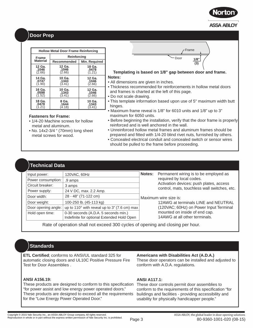
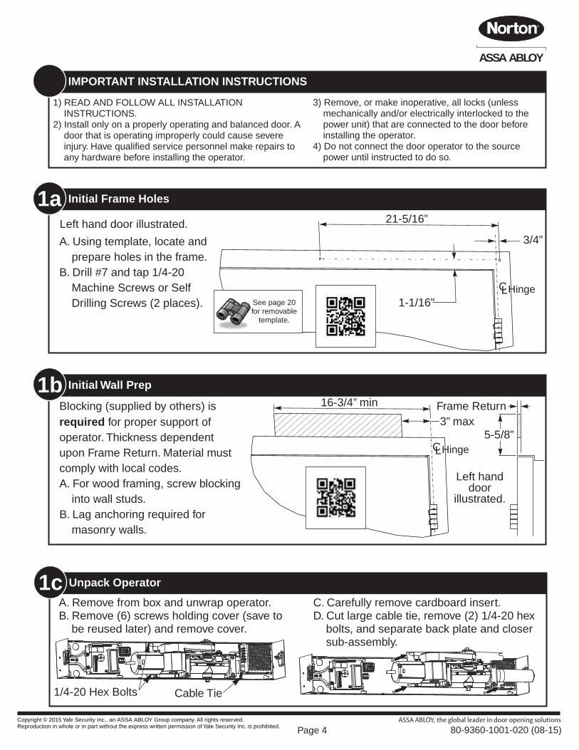
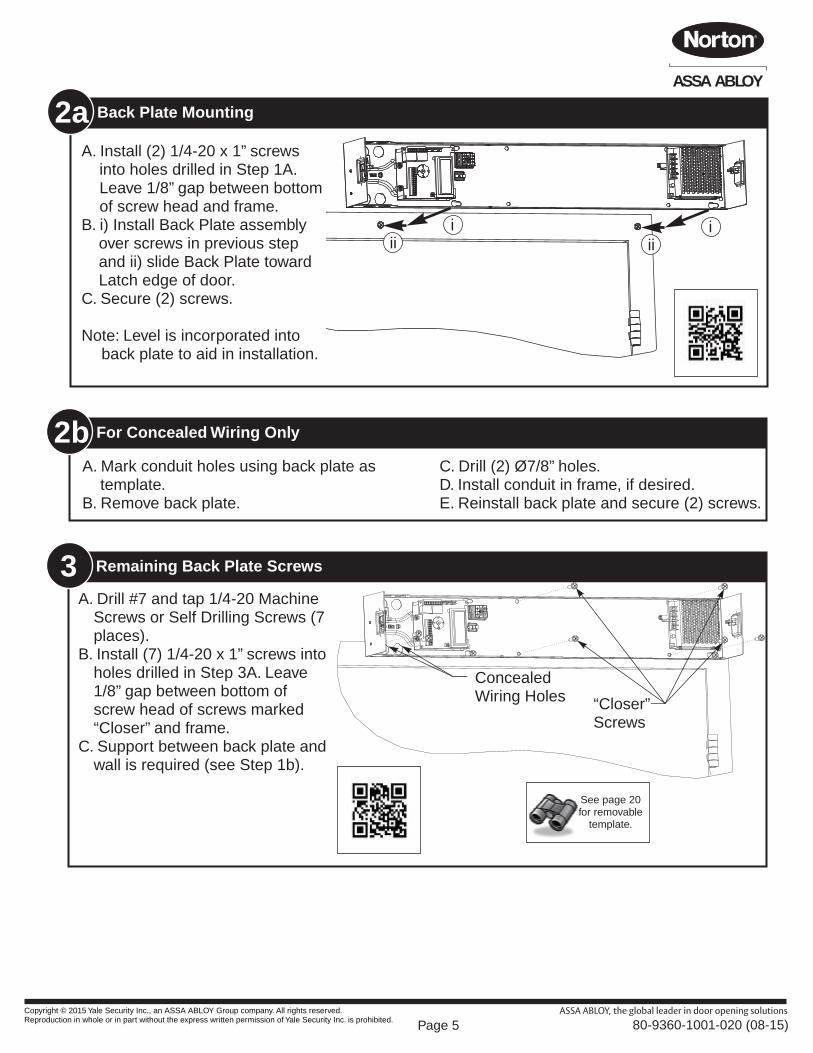
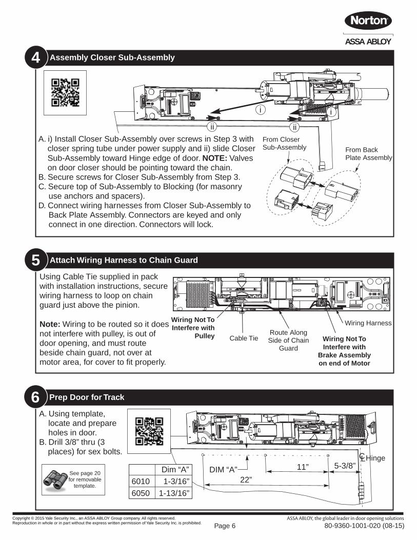
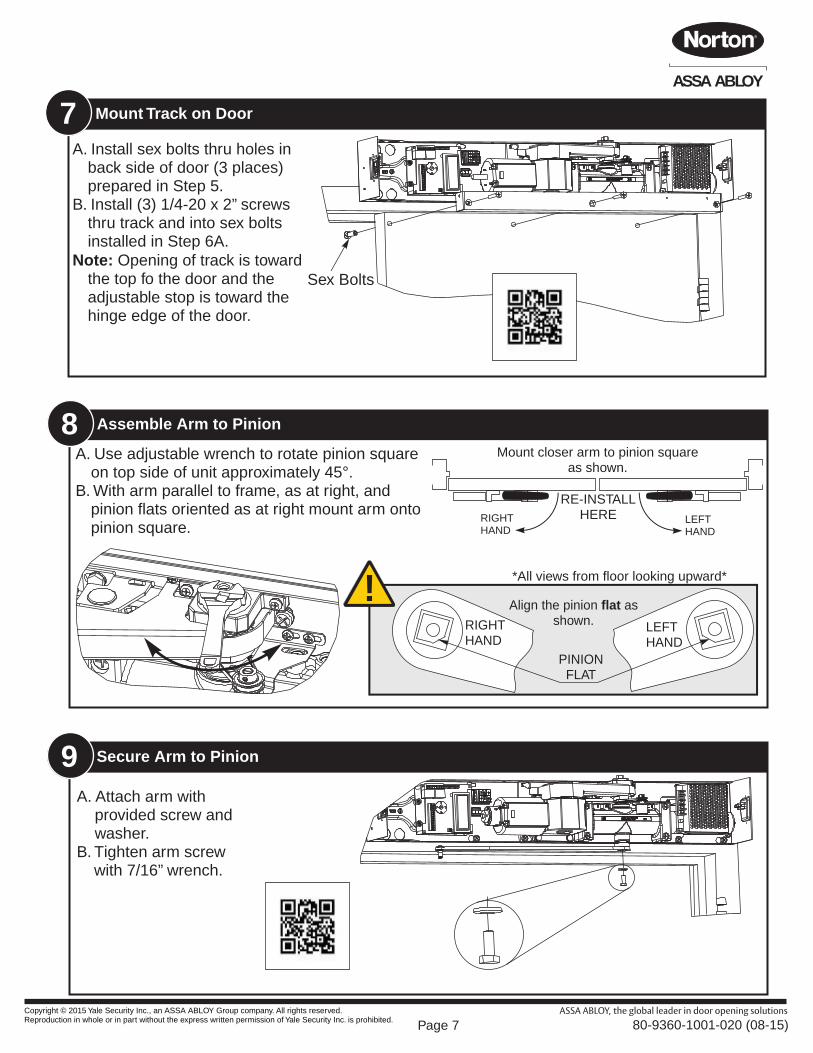
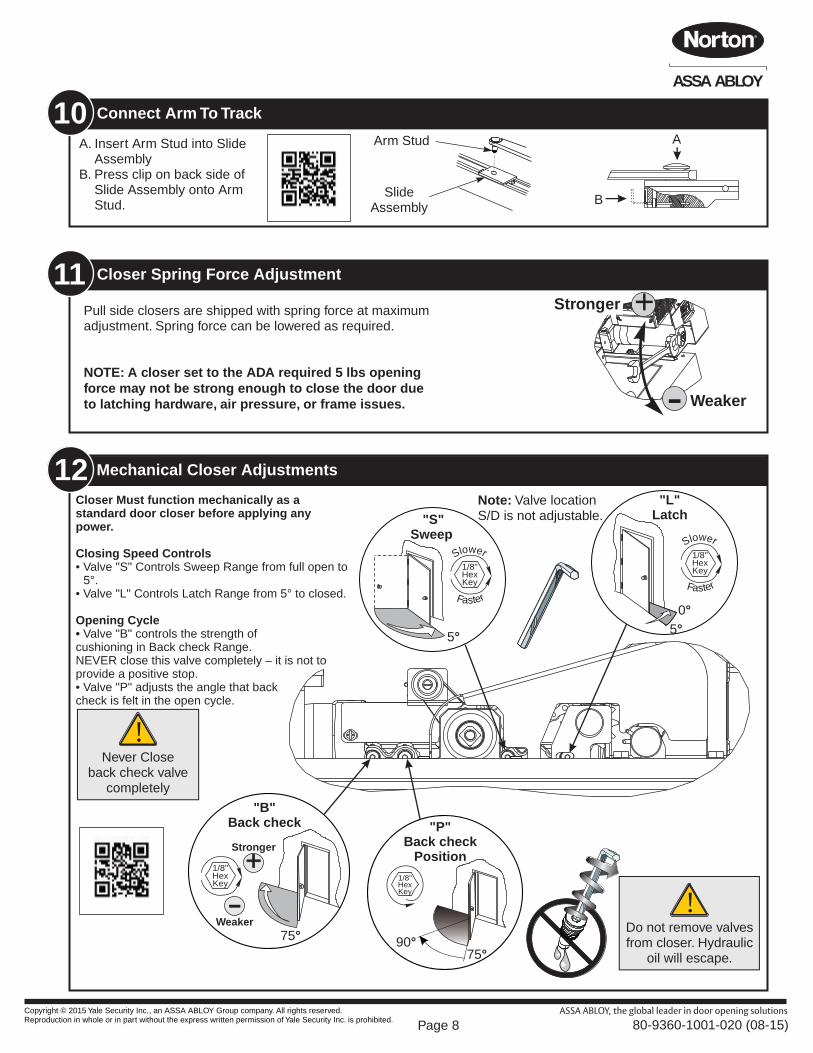
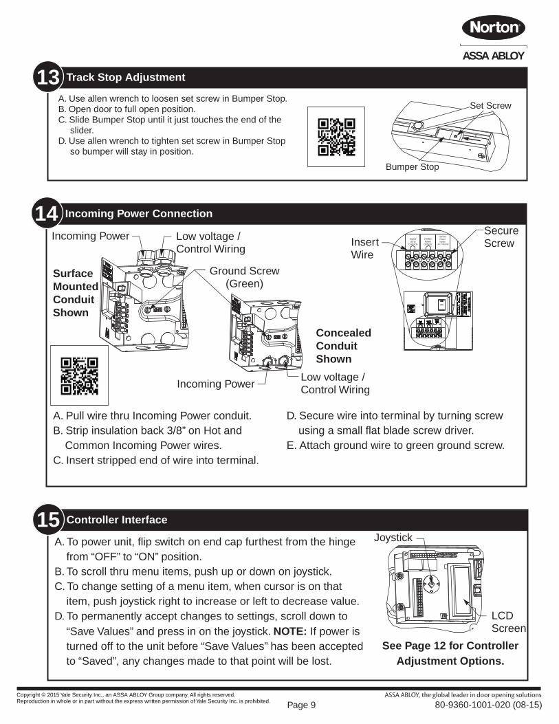
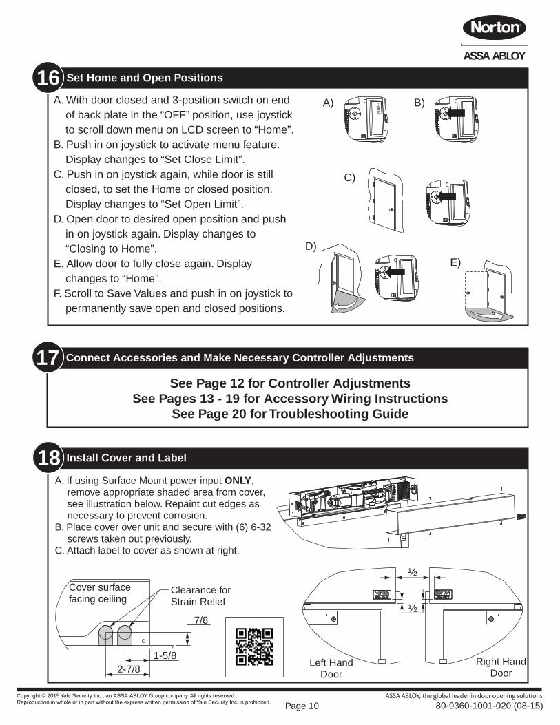
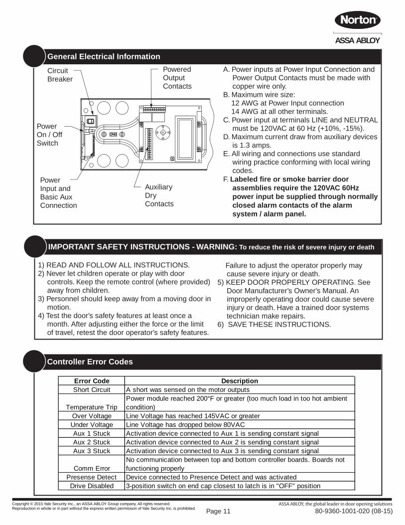
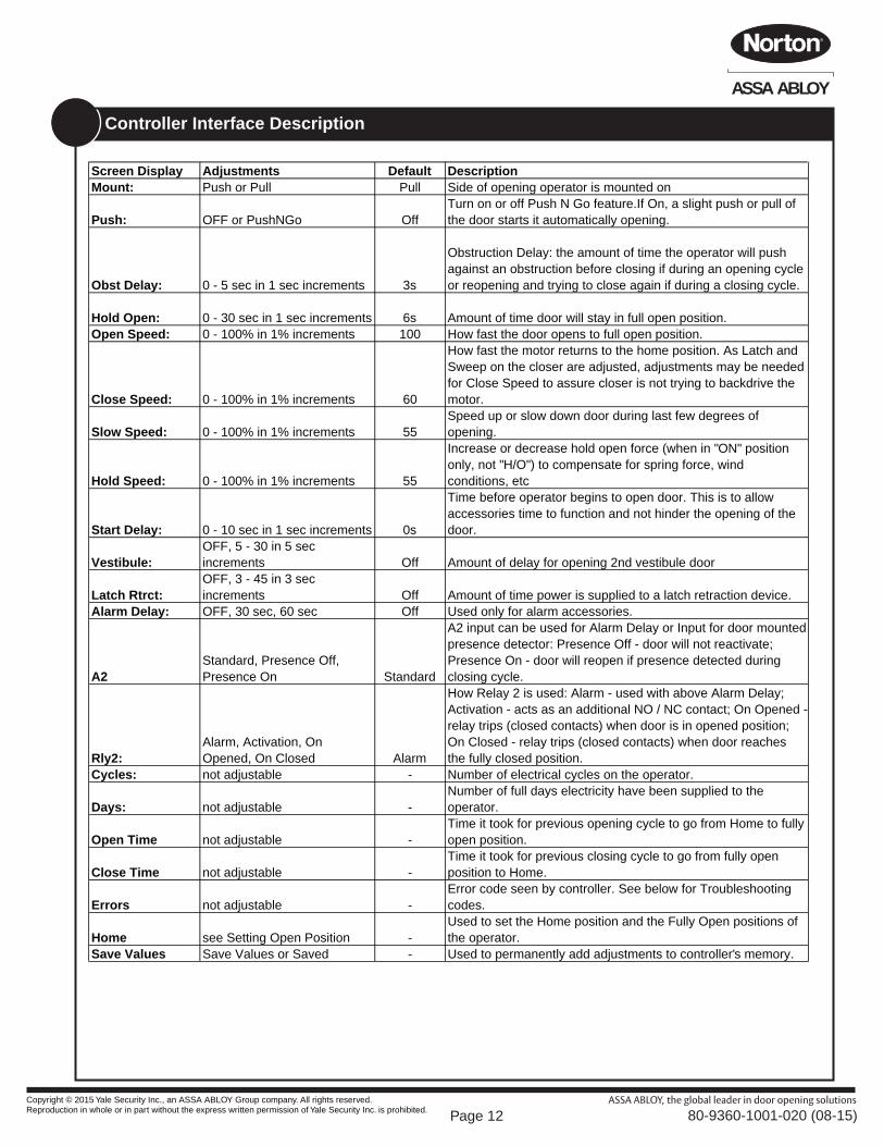
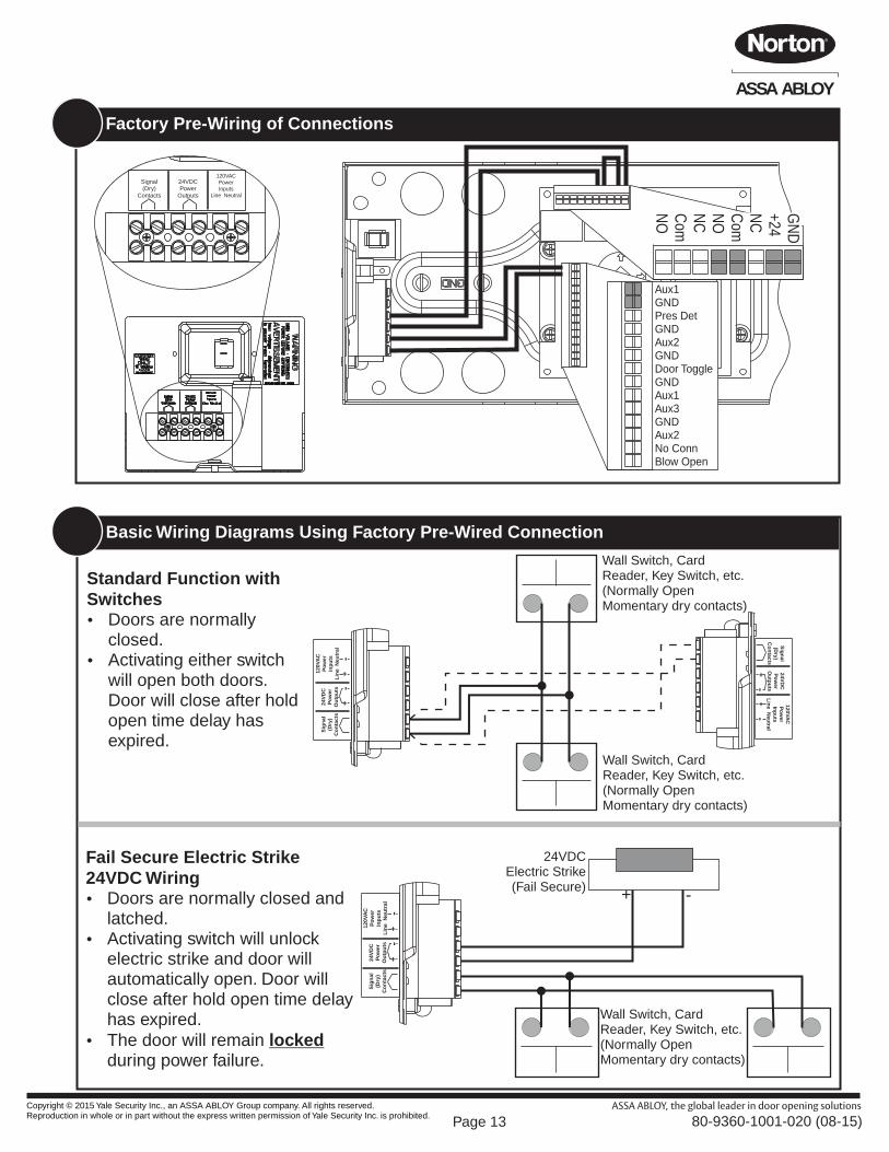
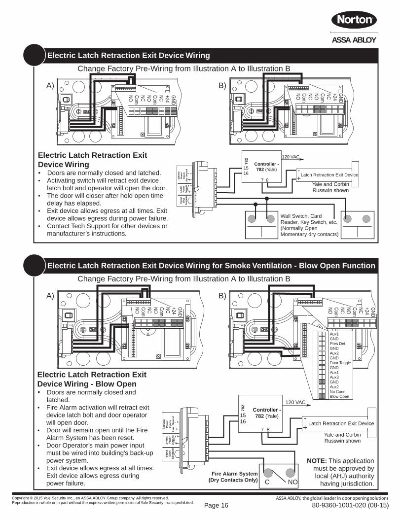
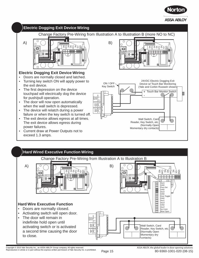
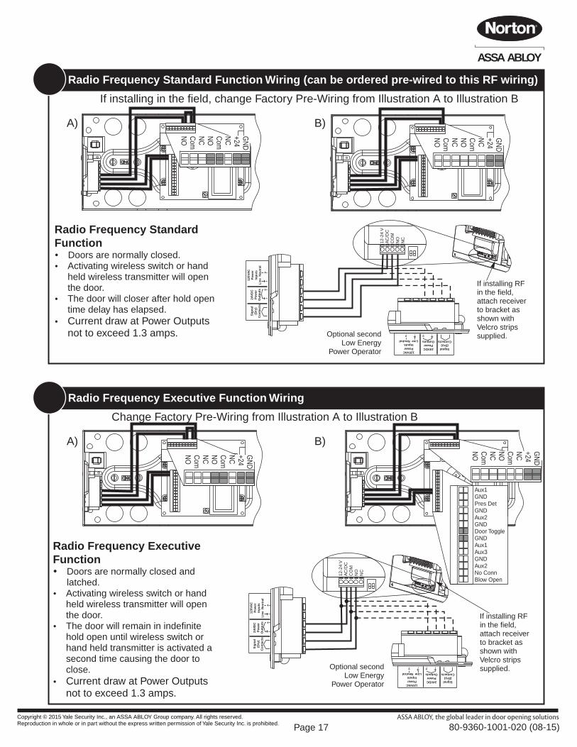
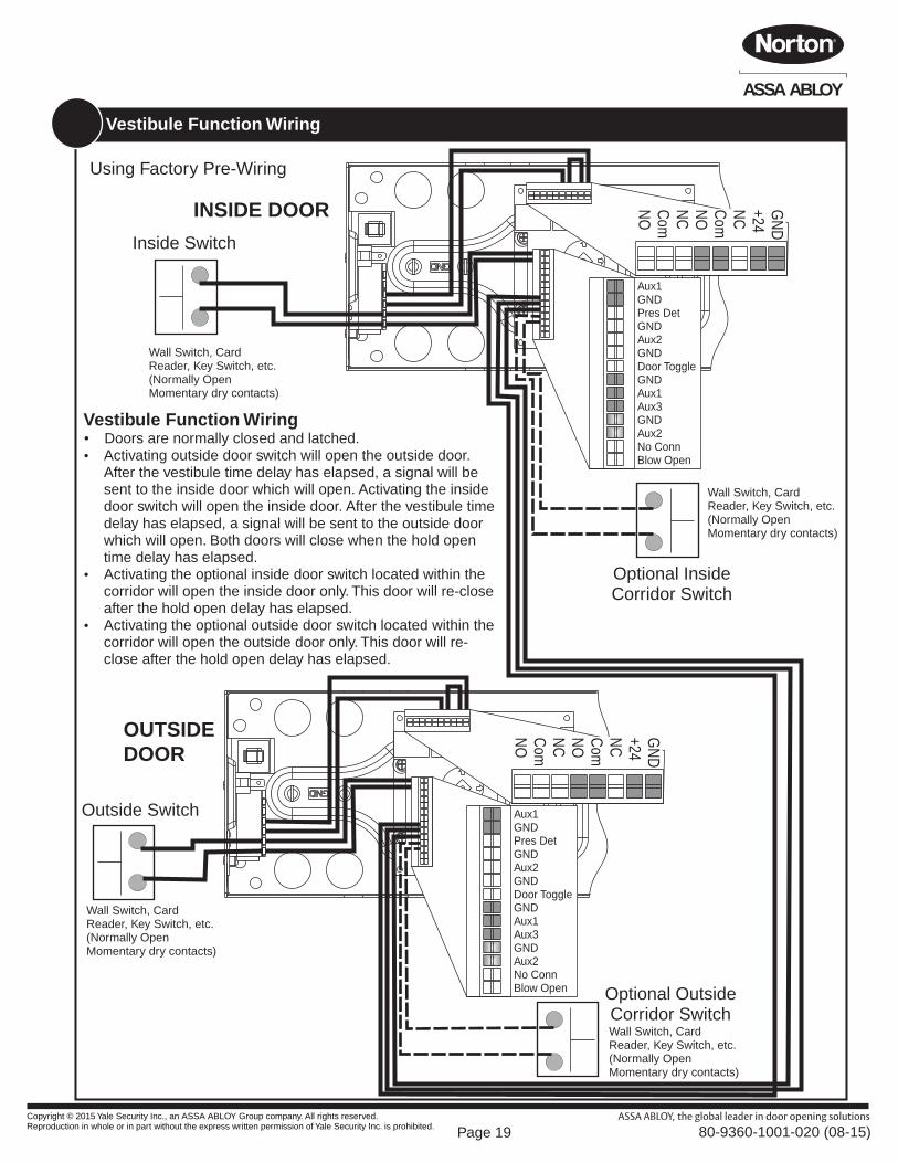
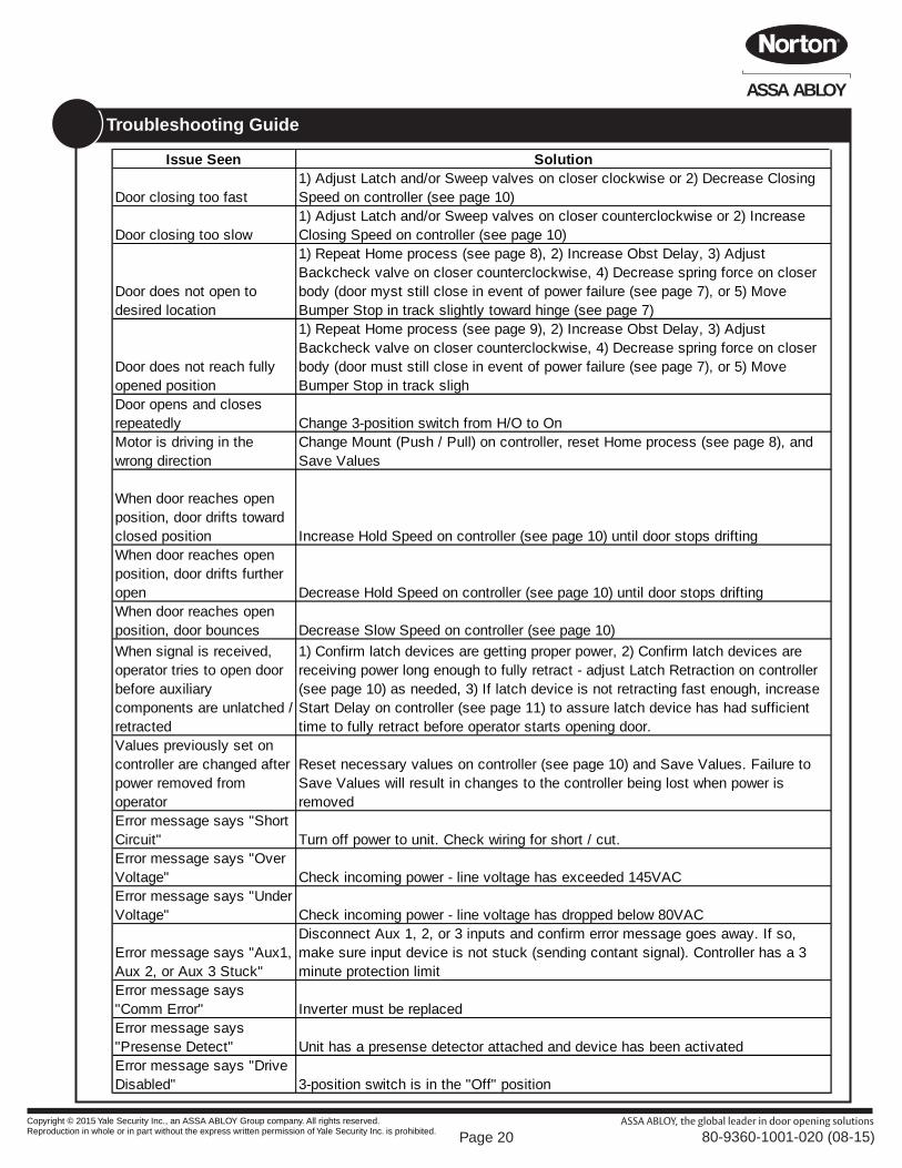
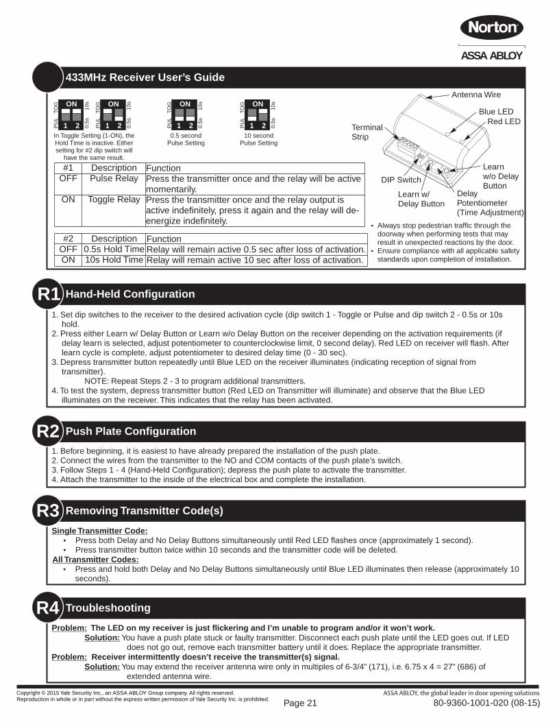
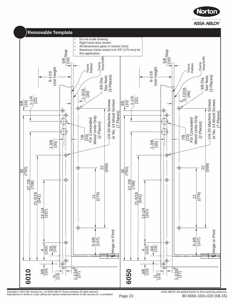

Page 24
ASSA ABLOY
This PageLeft Blank
Copyright copy 2015 Yale Security Inc an ASSA ABLOY Group company All rights reserved Reproduction in whole or in part without the express written permission of Yale Security Inc is prohibited 80-9360-1001-020 (08-15)