ASSA ABLOY · ASSA ABLOY ... assa abloy
16
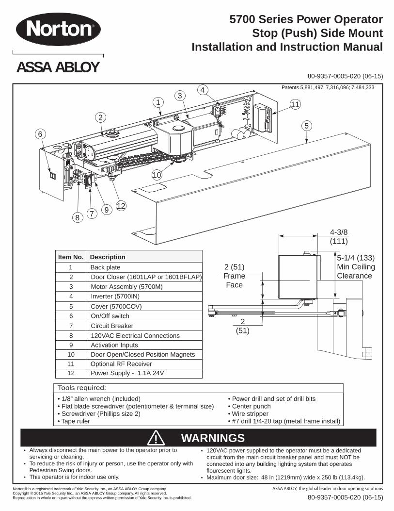
Norton® is a registered trademark of Yale Security Inc., an ASSA ABLOY Group company. Copyright © 2015 Yale Security Inc., an ASSA ABLOY Group company. All rights reserved. Reproduction in whole or in part without the express written permission of Yale Security Inc. is prohibited. 80-9357-0005-020 ( ) 06-15 6 2 3 1 4 8 7 9 12 10 5 11 ASSA ABLOY 80-9357-0005-020 (06-15) Tools required: • 1/8” allen wrench (included) • Power drill and set of drill bits • Flat blade screwdriver (potentiometer & terminal size) • Center punch • Screwdriver (Phillips size 2) • Wire stripper • Tape ruler • #7 drill 1/4-20 tap (metal frame install) 5700 Power Operator Stop (Push) Side Mount Installation and Instruction Manual Series Item No. Description 1 Back plate 2 Door Closer (1601LAP or 1601BFLAP) 3 Motor Assembly (5700M) 4 Inverter (5700IN) 5 Cover (5700COV) 6 On/Off switch 7 Circuit Breaker 8 120VAC Electrical Connections 9 Activation Inputs 10 Door Open/Closed Position Magnets 11 Optional RF Receiver 12 Power Supply - 1.1A 24V • Always disconnect the main power to the operator prior to servicing or cleaning. • To reduce the risk of injury or person, use the operator only with Pedestrian Swing doors. • This operator is for indoor use only. • 120VAC power supplied to the operator must be a dedicated circuit from the main circuit breaker panel and must NOT be connected into any building lighting system that operates flourescent lights. • Maximum door size: 48 in (1219mm) wide x 250 lb (113.4kg). WARNINGS ! Patents 5,881,497; 7,316,096; 7,484,333 5-1/4 (133) Min Ceiling Clearance 4-3/8 (111) 2 (51) Frame Face 2 (51)
Transcript of ASSA ABLOY · ASSA ABLOY ... assa abloy
Norton® is a registered trademark of Yale Security Inc., an ASSA ABLOY Group company. Copyright © 2015 Yale Security Inc., an ASSA ABLOY Group company. All rights reserved. Reproduction in whole or in part without the express written permission of Yale Security Inc. is prohibited.
ASSA ABLOY
80-9357-0005-020 ( )06-15
6
2
31
4
8 7 9 12
10
5
11
ASSA ABLOY80-9357-0005-020 (06-15)
Tools required:
• 1/8” allen wrench (included) • Power drill and set of drill bits• Flat blade screwdriver (potentiometer & terminal size) • Center punch• Screwdriver (Phillips size 2) • Wire stripper• Tape ruler • #7 drill 1/4-20 tap (metal frame install)
5700 Power OperatorStop (Push) Side Mount
Installation and Instruction Manual
Series
Item No. Description
1 Back plate
2 Door Closer (1601LAP or 1601BFLAP)
3 Motor Assembly (5700M)
4 Inverter (5700IN)
5 Cover (5700COV)
6 On/Off switch
7 Circuit Breaker
8 120VAC Electrical Connections
9 Activation Inputs
10 Door Open/Closed Position Magnets
11 Optional RF Receiver12 Power Supply - 1.1A 24V
· Always disconnect the main power to the operator prior to servicing or cleaning.
· To reduce the risk of injury or person, use the operator only with Pedestrian Swing doors.
· This operator is for indoor use only.
· 120VAC power supplied to the operator must be a dedicated circuit from the main circuit breaker panel and must NOT be connected into any building lighting system that operates flourescent lights.
· Maximum door size: 48 in (1219mm) wide x 250 lb (113.4kg).
WARNINGS!
Patents 5,881,497; 7,316,096; 7,484,333
5-1/4 (133)Min CeilingClearance
4-3/8(111)
2 (51)FrameFace
2(51)

Norton® is a registered trademark of Yale Security Inc., an ASSA ABLOY Group company. Copyright © 2015 Yale Security Inc., an ASSA ABLOY Group company. All rights reserved. Reproduction in whole or in part without the express written permission of Yale Security Inc. is prohibited.
ASSA ABLOY
80-9357-0005-020 ( )06-15Page 2
Hollow Metal Door Frame Reinforcing
FrameMaterial
12 Ga..1046 (2.66)
14 Ga..0747 (1.90)
16 Ga..0598 (1.52)
18 Ga..0478 (1.21)
12 Ga..1046 (2.66)
10 Ga..1343 (3.41)
10 Ga..1343 (3.41)
8 Ga..1644 (4.18)
18 Ga..0478 (1.21)
12 Ga..1046 (2.66)
12 Ga..1046 (2.66)
10 Ga..1343 (3.41)
Reinforcing
Recommended Min. Required
Contents
General Information· UL labeled fire or smoke barrier door assemblies require that
the 120VAC (60Hz) power input to the LEO door operator be supplied through normally closed alarm contacts of the alarm system / alarm panel.
· Power input to LEO door operator must be 120VAC (60Hz) to terminals HOT and COM at terminal strip T1. Earth ground (GND) to green screw on backplate.
· All wiring must conform to standard wiring practice in accordance with national and local wiring codes.
· Note: Unless otherwise noted, all dimensions are given in inches (millimeters).
· Minimum suggested and required material thickness for hollow metal frames (skin plus reinforcement) is charted on below.
· Unit is Non-Handed.
· Door must be hung on butt hinges [5” (127mm) max. width] or 3/4” (19mm) offset pivots. A separate door and frame preparation template will be supplied for other conditions.
· Door must swing freely through the entire opening and closing cycle before beginning the installation.
· Use of an auxiliary door stop (by others) is always recommended.
· An incorrectly installed or improperly adjusted door operator can cause property damage or personal injury. These instructions should be followed to avoid the possibility of misapplication or misadjustment.
WARNING: Make sure 120VAC (60Hz) input power is turned off at facility’s main circuit breaker before proceeding with installation.
General Templating Information:· Before beginning the installation, verify that the door frame is
properly reinforced and is well anchored in the wall.
· Unreinforced hollow metal frames and aluminum frames should be prepared and fitted with 1/4-20 blind rivet nuts, furnished by others.
· Concealed electrical conduit and concealed switch or sensor wires should be pulled to the frame before proceeding.
Fasteners for Frame:· 1/4-20 machine screws for hollow metal and aluminum.· No. 14 x 2-3/4” (70mm) long sheet metal screws for wood.
Fasteners for Door:· 1/4-20 machine screws.· 3/8” diameter x 1-5/8” (41mm) long sex nut.
Electrical Information:· Maximum current draw of unit is 0.6 amps.
· Breaker Switch protects the motor assembly and inverter; and has a 3 amp rating.
· Maximum wire size is:12AWG at terminals HOT and COM (120VAC; 60Hz) on “T1” Power Input Terminal.14AWG at terminals 1 thru 4 on Accessory Terminal .18AWG at terminals 22 thru 25 on “T1” Power Input Terminal.
Frame Reinforcement Table Technical Data
120VAC, 60Hz
.6 amps
24 V DC, max. 1.1 Amp.
28 - 48" (71-122 cm)
100-250 lb. (45-113 kg)
Input power:
Power consumption:
Power supply:
Door width:
Door weight:
Door opening angle:
Hold open time: 5 - 30 seconds (A.D.A. 5 seconds min.)
3 ampsCircuit breaker:
up to 110° Pull side; up to 170 Push side;Manually to 180° Push/Pull side
°
General 2Frame Reinforcement Table / Technical Data 2Component Layout 3ADA / ANSI / UL 3Stop (Push) Side Mounting 4Adjust Power and Opening / Closing Cycle 7Input Power Configuration 8
Final Setup 8Inverter Details 9Accessory / Typical Installations 10Troubleshooting 10RF Receiver Setup 12RH Door Template 14LH Door Template 15
Norton® is a registered trademark of Yale Security Inc., an ASSA ABLOY Group company. Copyright © 2015 Yale Security Inc., an ASSA ABLOY Group company. All rights reserved. Reproduction in whole or in part without the express written permission of Yale Security Inc. is prohibited.
ASSA ABLOY
80-9357-0005-020 ( )06-15
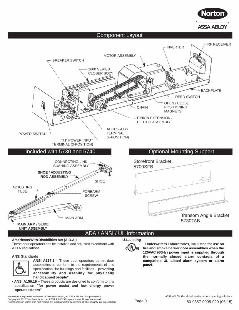
BACKPLATE
REED SWITCH
CHAINOPEN / CLOSE POSITIONING MAGNETS
“T1” POWER INPUTTERMINAL (3-POSITION)
ACCESSORYTERMINAL(4-POSITION)
PINION EXTENSION / CLUTCH ASSEMBLY
INVERTER
MOTOR ASSEMBLY
POWER SWITCH
BREAKER SWITCH
1600 SERIES CLOSER BODY
Component Layout
ADA / ANSI / UL InformationAmericans With Disabilities Act (A.D.A.)These door operators can be installed and adjusted to conform with A.D.A. regulations.
ANSI StandardsANSI A117.1 – These door operators permit door assemblies to conform to the requirements of this specification "for buildings and facilities – providing accessibility and usability for physically handicapped people".
• ANSI A156.19 – These products are designed to conform to this specification "for power assist and low energy power operated doors".
U.L. Listing Underwriters Laboratories, Inc. listed for use on
fire and smoke barrier door assemblies when the 120VAC (60Hz) power input is supplied through the normally closed alarm contacts of a compatible UL Listed alarm system or alarm panel.
Page 3
RF RECEIVER
Optional Mounting Support
Storefront Bracket5700SFB
Transom Angle Bracket5730TAB
CONNECTING LINKBUSHING ASSEMBLY
SHOE
SHOE / ADJUSTING ROD ASSEMBLY
FOREARMSCREW
MAIN ARM
ADJUSTINGTUBE
MAIN ARM / SLIDEUNIT ASSEMBLY
Included with 5730 and 5740
Norton® is a registered trademark of Yale Security Inc., an ASSA ABLOY Group company. Copyright © 2015 Yale Security Inc., an ASSA ABLOY Group company. All rights reserved. Reproduction in whole or in part without the express written permission of Yale Security Inc. is prohibited.
ASSA ABLOY
80-9357-0005-020 ( )06-15
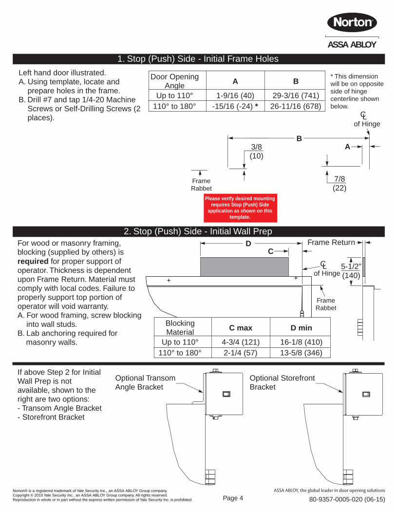
1. Stop (Push) Side - Initial Frame Holes
Page 4
AB
7/8(22)
3/8(10)
FrameRabbet
Left hand door illustrated.A. Using template, locate and
prepare holes in the frame.B. Drill #7 and tap 1/4-20 Machine
Screws or Self-Drilling Screws (2 places).
* This dimension will be on oppositeside of hinge centerline shown below.
CLof Hinge
Door OpeningAngle
Up to 110°110° to 180°
A
1-9/16 (40)-15/16 (-24) *
B
29-3/16 (741)26-11/16 (678)
RH DoorLH Door
BA 3/8
(10)
7/8(22)
CL of Hinge
LH Door shown (RH Door opposite)
LeftHandDoor
RightHandDoor
2. Stop (Push) Side - Initial Wall PrepFor wood or masonry framing, blocking (supplied by others) is required for proper support of operator. Thickness is dependent upon Frame Return. Material must comply with local codes. Failure to properly support top portion of operator will void warranty.A. For wood framing, screw blocking
into wall studs.B. Lab anchoring required for
masonry walls.
5-1/2”(140)
Frame ReturnC
D
FrameRabbet
CLof Hinge
BlockingMaterial
Up to 110°110° to 180°
C max
4-3/4 (121)2-1/4 (57)
D min
16-1/8 (410)13-5/8 (346)
If above Step 2 for Initial Wall Prep is not available, shown to the right are two options:- Transom Angle Bracket- Storefront Bracket
Optional TransomAngle Bracket
Optional StorefrontBracket
Please verify desired mounting requires Stop (Push) Side
application as shown on this template.
Norton® is a registered trademark of Yale Security Inc., an ASSA ABLOY Group company. Copyright © 2015 Yale Security Inc., an ASSA ABLOY Group company. All rights reserved. Reproduction in whole or in part without the express written permission of Yale Security Inc. is prohibited.
ASSA ABLOY
80-9357-0005-020 ( )06-15Page 5
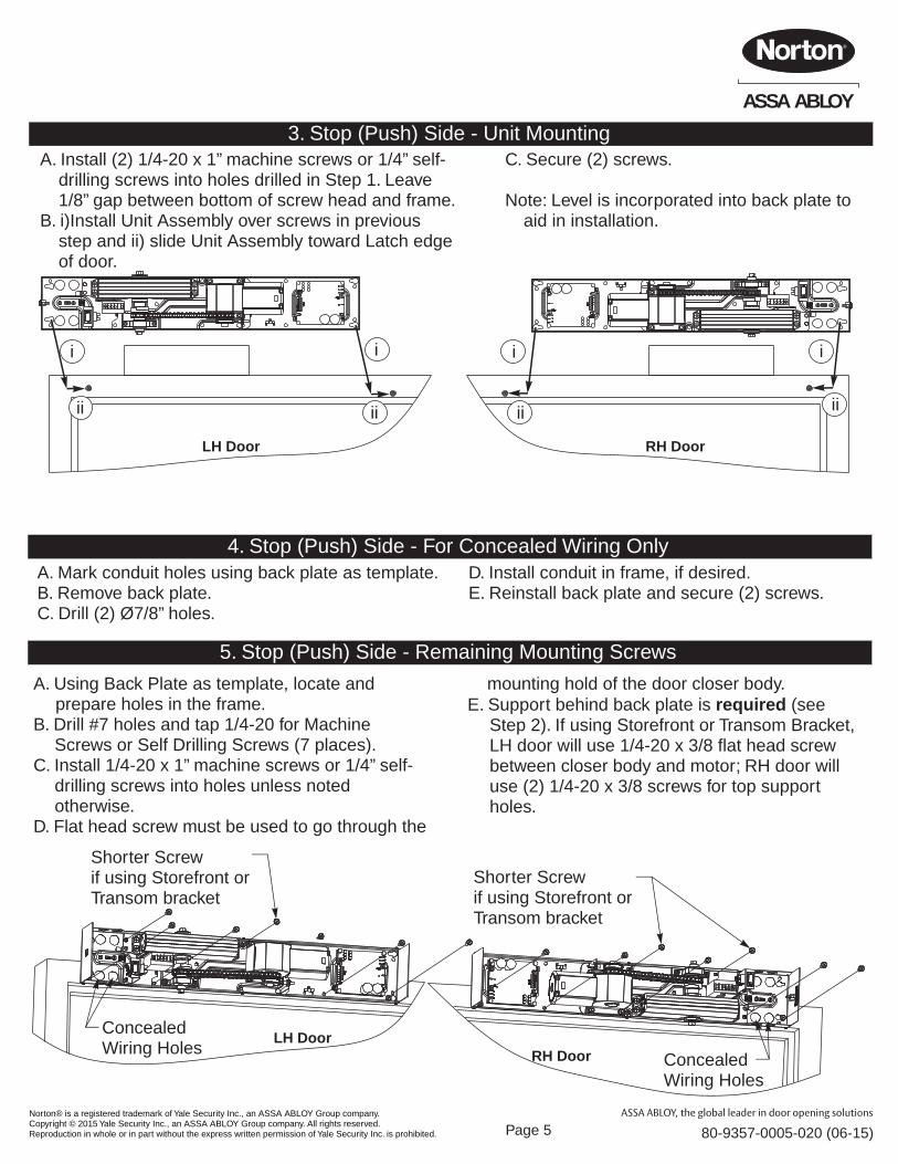
3. Stop (Push) Side - Unit MountingA. Install (2) 1/4-20 x 1” machine screws or 1/4” self-
drilling screws into holes drilled in Step 1. Leave 1/8” gap between bottom of screw head and frame.
B. i)Install Unit Assembly over screws in previous step and ii) slide Unit Assembly toward Latch edge of door.
i
ii
i
ii
i
ii
i
ii
C. Secure (2) screws.
Note: Level is incorporated into back plate to aid in installation.
mounting hold of the door closer body.E. Support behind back plate is required (see
Step 2). If using Storefront or Transom Bracket, LH door will use 1/4-20 x 3/8 flat head screw between closer body and motor; RH door will use (2) 1/4-20 x 3/8 screws for top support holes.
RH DoorLH Door
RH DoorLH Door
ConcealedWiring Holes
ConcealedWiring Holes
Shorter Screwif using Storefront orTransom bracket
4. Stop (Push) Side - For Concealed Wiring OnlyA. Mark conduit holes using back plate as template.B. Remove back plate.C. Drill (2) Ø7/8” holes.
D. Install conduit in frame, if desired.E. Reinstall back plate and secure (2) screws.
5. Stop (Push) Side - Remaining Mounting Screws
A. Using Back Plate as template, locate and prepare holes in the frame.
B. Drill #7 holes and tap 1/4-20 for Machine Screws or Self Drilling Screws (7 places).
C. Install 1/4-20 x 1” machine screws or 1/4” self-drilling screws into holes unless noted otherwise.
D. Flat head screw must be used to go through the
Shorter Screwif using Storefront orTransom bracket
Norton® is a registered trademark of Yale Security Inc., an ASSA ABLOY Group company. Copyright © 2015 Yale Security Inc., an ASSA ABLOY Group company. All rights reserved. Reproduction in whole or in part without the express written permission of Yale Security Inc. is prohibited.
ASSA ABLOY
80-9357-0005-020 ( )06-15
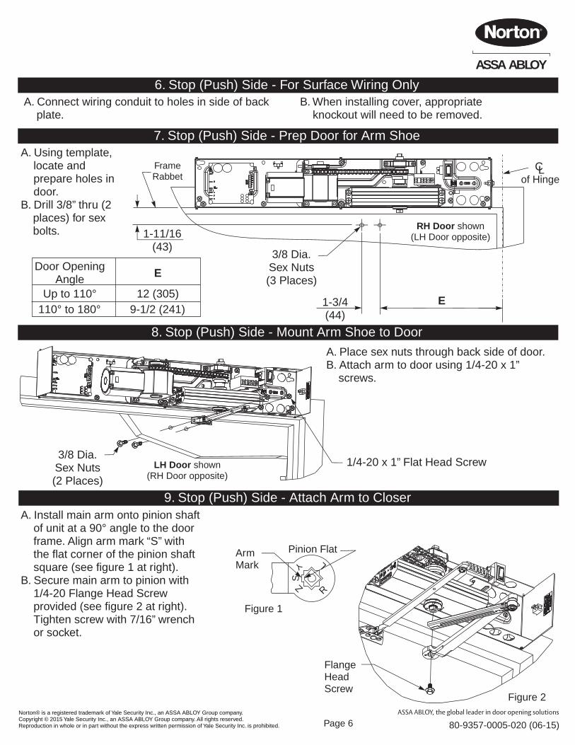
6. Stop (Push) Side - For Surface Wiring OnlyA. Connect wiring conduit to holes in side of back
plate.B. When installing cover, appropriate
knockout will need to be removed.
7. Stop (Push) Side - Prep Door for Arm ShoeA. Using template,
locate and prepare holes in door.
B. Drill 3/8” thru (2 places) for sex bolts.
CLof Hinge
1-3/4(44)
E
RH Door shown(LH Door opposite)1-11/16
(43)
FrameRabbet
3/8 Dia.Sex Nuts(3 Places)
8. Stop (Push) Side - Mount Arm Shoe to Door
LH Door shown(RH Door opposite)
3/8 Dia.Sex Nuts(2 Places)
1/4-20 x 1” Flat Head Screw
A. Place sex nuts through back side of door.B. Attach arm to door using 1/4-20 x 1”
screws.
9. Stop (Push) Side - Attach Arm to CloserA. Install main arm onto pinion shaft
of unit at a 90° angle to the door frame. Align arm mark “S” with the flat corner of the pinion shaft square (see figure 1 at right).
B. Secure main arm to pinion with 1/4-20 Flange Head Screw provided (see figure 2 at right). Tighten screw with 7/16” wrench or socket.
Page 6
Door OpeningAngle
Up to 110°110° to 180°
E
12 (305)9-1/2 (241)
R
LY
S
Z
Arm Mark
Pinion Flat
Figure 1
Figure 2
FlangeHeadScrew
Norton® is a registered trademark of Yale Security Inc., an ASSA ABLOY Group company. Copyright © 2015 Yale Security Inc., an ASSA ABLOY Group company. All rights reserved. Reproduction in whole or in part without the express written permission of Yale Security Inc. is prohibited.
ASSA ABLOY
80-9357-0005-020 ( )06-15
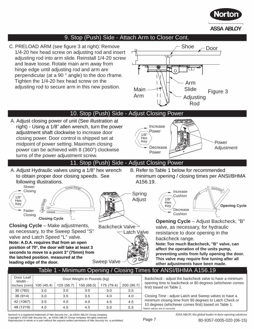
9. Stop (Push) Side - Attach Arm to Closer Cont.
Power Adjustment
1/8"HexKey
IncreasePower
DecreasePower
10. Stop (Push) Side - Adjust Closing PowerA. Adjust closing power of unit (See illustration at
right) - Using a 1/8” allen wrench, turn the power adjustment shaft clockwise to increase door closing power. Door control is shipped set at midpoint of power setting. Maximum closing power can be achieved with 8 (360°) clockwise turns of the power adjustment screw.
1A. Installation Sequence ContinuedTable 1 - Minimum Opening / Closing Times for ANSI/BHMA A156.19Door Weight in Pounds (kg)Door Leaf
Width -Inches (mm)
Matrix values are in seconds.
Backcheck - adjust the backcheck valve to have a minimum opening time to backcheck or 80 degrees (whichever comes first) based on Table 1.
Closing Time - adjust Latch and Sweep valves to have a minimum closing time from 90 degrees to Latch Check or 10 degrees (whichever comes first) based on Table 1.
11. Stop (Push) Side - Adjust Closing Power
1/8"HexKey
SlowerClosing
FasterClosing
Closing Cycle
Closed
10°
egnaR hct aL
egnaR peewS
1/8"HexKey
IncreaseCushion
DecreaseCushion
Opening Cycle
Backcheckgninep
O
A. Adjust Hydraulic valves using a 1/8” hex wrench to obtain proper door closing speeds. See following illustrations.
B. Refer to Table 1 below for recommended minimum opening / closing times per ANSI/BHMA A156.19.
Closing Cycle – Make adjustments, as necessary, to the Sweep Speed "S" valve and Latch Speed "L" valve. Note: A.D.A. requires that from an open position of 70°, the door will take at least 3 seconds to move to a point 3” (75mm) from the latched position, measured at the leading edge of the door.
Opening Cycle – Adjust Backcheck, "B" valve, as necessary, for hydraulic resistance to door opening in the backcheck range. Note: Too much Backcheck, "B" valve, can affect the operation of the units pump, preventing units from fully opening the door. This valve may require fine tuning after all other adjustments have been made.Sweep Valve
Latch ValveBackcheck Valve
SpringAdjust
Page 7
Figure 3Adjusting
Rod
ArmSlide
DoorShoe
MainArm
C. PRELOAD ARM (see figure 3 at right): Remove 1/4-20 hex head screw on adjusting rod and insert adjusting rod into arm slide. Reinstall 1/4-20 screw and leave loose. Rotate main arm away from hinge edge until adjusting rod and arm are perpendicular (at a 90 ° angle) to the doo rframe. Tighten the 1/4-20 hex head screw on the adjusting rod to secure arm in this new position.
Norton® is a registered trademark of Yale Security Inc., an ASSA ABLOY Group company. Copyright © 2015 Yale Security Inc., an ASSA ABLOY Group company. All rights reserved. Reproduction in whole or in part without the express written permission of Yale Security Inc. is prohibited.
ASSA ABLOY
80-9357-0005-020 ( )06-15
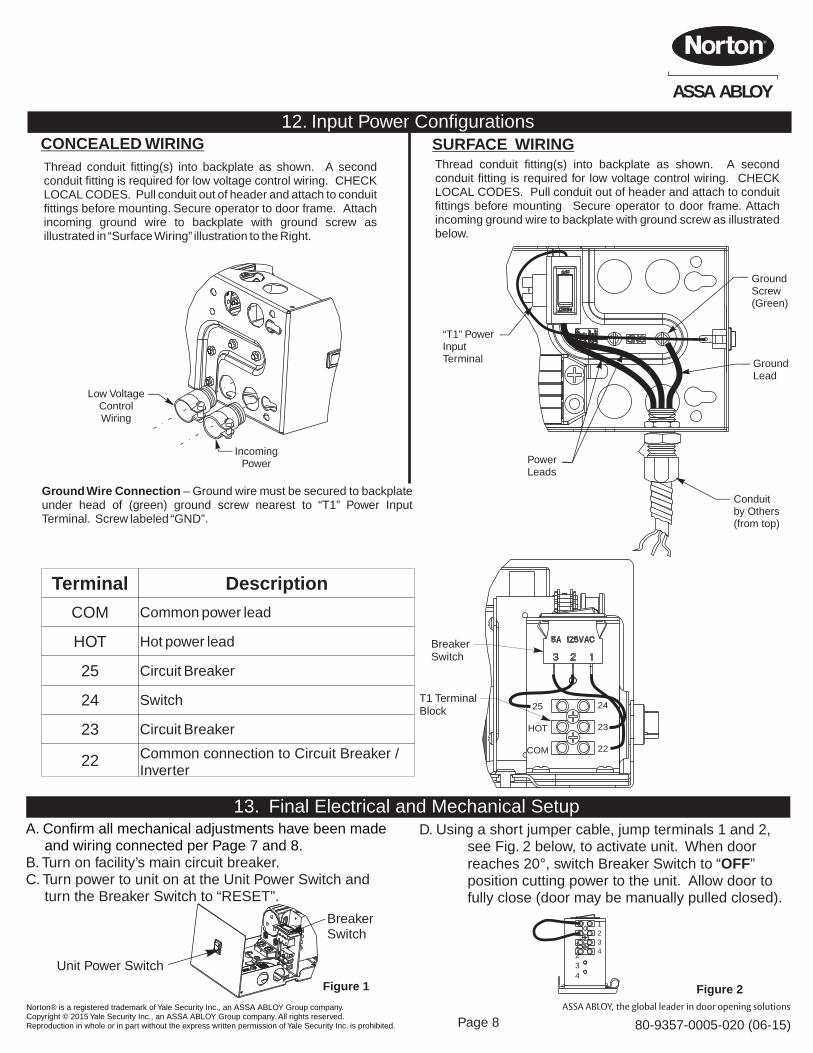
13. Final Electrical and Mechanical SetupA. Confirm all mechanical adjustments have been made
and wiring connected per Page 7 and 8.B. Turn on facility’s main circuit breaker.C. Turn power to unit on at the Unit Power Switch and
turn the Breaker Switch to “RESET”.
D. Using a short jumper cable, jump terminals 1 and 2, see Fig. 2 below, to activate unit. When door reaches 20°, switch Breaker Switch to “OFF” position cutting power to the unit. Allow door to fully close (door may be manually pulled closed).
Breaker Switch
Unit Power Switch
1234
1234
Figure 2Figure 1
Page 8
Low VoltageControlWiring
IncomingPower
12. Input Power ConfigurationsCONCEALED WIRING SURFACE WIRING
Ground Wire Connection – Ground wire must be secured to backplate under head of (green) ground screw nearest to “T1” Power Input Terminal. Screw labeled “GND”.
Terminal Description
HOT
25
23
24
22
COM Common power lead
Hot power lead
Circuit Breaker
Switch
Circuit Breaker
Common connection to Circuit Breaker / Inverter
Thread conduit fitting(s) into backplate as shown. A second conduit fitting is required for low voltage control wiring. CHECK LOCAL CODES. Pull conduit out of header and attach to conduit fittings before mounting. Secure operator to door frame. Attach incoming ground wire to backplate with ground screw as illustrated in “Surface Wiring” illustration to the Right.
Thread conduit fitting(s) into backplate as shown. A second conduit fitting is required for low voltage control wiring. CHECK LOCAL CODES. Pull conduit out of header and attach to conduit fittings before mounting Secure operator to door frame. Attach incoming ground wire to backplate with ground screw as illustrated below.
GroundLead
PowerLeads
GroundScrew(Green)
Conduitby Others(from top)
“T1” PowerInputTerminal
24
23
22
25
HOT
COM
BreakerSwitch
T1 TerminalBlock
Norton® is a registered trademark of Yale Security Inc., an ASSA ABLOY Group company. Copyright © 2015 Yale Security Inc., an ASSA ABLOY Group company. All rights reserved. Reproduction in whole or in part without the express written permission of Yale Security Inc. is prohibited.
ASSA ABLOY
80-9357-0005-020 ( )06-15
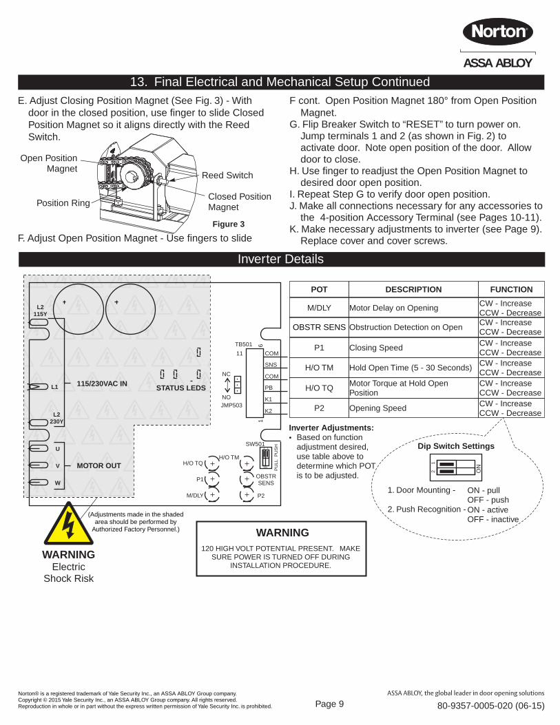
13. Final Electrical and Mechanical Setup ContinuedE. Adjust Closing Position Magnet (See Fig. 3) - With
door in the closed position, use finger to slide Closed Position Magnet so it aligns directly with the Reed Switch.
F. Adjust Open Position Magnet - Use fingers to slide
F cont. Open Position Magnet 180° from Open Position Magnet.
G. Flip Breaker Switch to “RESET” to turn power on. Jump terminals 1 and 2 (as shown in Fig. 2) to activate door. Note open position of the door. Allow door to close.
H. Use finger to readjust the Open Position Magnet to desired door open position.
I. Repeat Step G to verify door open position. J. Make all connections necessary for any accessories to
the 4-position Accessory Terminal (see Pages 10-11).K. Make necessary adjustments to inverter (see Page 9).
Replace cover and cover screws.
Reed Switch
Closed Position Magnet
Open PositionMagnet
Position Ring
Figure 3
Page 9
Inverter Adjustments:· Based on function
adjustment desired, use table above to determine which POT is to be adjusted.
POT FUNCTIONDESCRIPTION
OBSTR SENS Obstruction Detection on Open CW - IncreaseCCW - Decrease
M/DLY Motor Delay on Opening CW - IncreaseCCW - Decrease
P1 Closing Speed CW - IncreaseCCW - Decrease
H/O TM Hold Open Time (5 - 30 Seconds) CW - IncreaseCCW - Decrease
P2 Opening Speed CW - IncreaseCCW - Decrease
H/O TQMotor Torque at Hold Open Position
CW - IncreaseCCW - Decrease
ON
12
WARNING
120 HIGH VOLT POTENTIAL PRESENT. MAKE SURE POWER IS TURNED OFF DURING
INSTALLATION PROCEDURE.
Dip Switch Settings
1. Door Mounting -
2. Push Recognition -
ON - pullOFF - pushON - activeOFF - inactive
WARNINGElectric
Shock Risk
(Adjustments made in the shaded area should be performed by
Authorized Factory Personnel.)
L2115Y
L1 115/230VAC IN
MOTOR OUT
L2230Y
U
V
W
STATUS LEDS
H/O TQH/O TM
OBSTRSENS
P1
M/DLY P2
16
COM
SNS
COM
PB
K1
K2
11
JMP503
NC
NO
TB501
PU
LL P
US
HSW501
ON
12
Inverter Details
Norton® is a registered trademark of Yale Security Inc., an ASSA ABLOY Group company. Copyright © 2015 Yale Security Inc., an ASSA ABLOY Group company. All rights reserved. Reproduction in whole or in part without the express written permission of Yale Security Inc. is prohibited.
ASSA ABLOY
80-9357-0005-020 ( )06-15
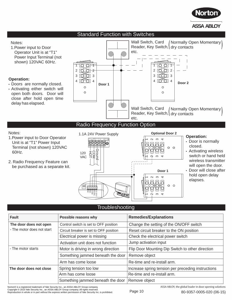
Standard Function with Switches
1
2
3
4
1
2
3
4
Notes:1.Power input to Door
Operator Unit is at “T1” Power Input Terminal (not shown) 120VAC 60Hz.
Wall Switch, CardReader, Key Switch,etc.
1
2
3
4
1
2
3
4Door 1 Door 2
Operation:· Doors are normally closed.· Activating either switch will
open both doors. Door will close after hold open time delay has elapsed.
Page 10
Wall Switch, CardReader, Key Switch,etc.
Normally Open Momentary dry contacts
Normally Open Momentary dry contacts
Radio Frequency Function Option
1 2 3 4
1 2 3 4
Optional Door 2
1 2 3 4
1 2 3 4
Door 1
Notes:1.Power input to Door Operator
Unit is at “T1” Power Input Terminal (not shown) 120VAC 60Hz.
2. Radio Frequency Feature can be purchased as a separate kit.
Operation:· Door is normally
closed.· Activating wireless
switch or hand held wireless transmitter will open the door.
· Door will close after hold open delay elapses.
120VAC
GroundC
OM
HO
TL N(AC) -V +V ADJ
+
1.1A 24V Power Supply12-24 VA
C/D
CC
OM
NO
NC
Troubleshooting
Jump activation input
Change the setting of the ON/OFF switch
Flip Door Mounting Dip Switch to other direction
Remove object
Re-time and re-install arm.
Increase spring tension per preceding instructions
Remove object
Fault Possible reasons why Remedies/Explanations
The door does not open- The motor does not start
Control switch is set to OFF position
Electrical power is missing the electrical Check power switch
Activation unit does not function- The motor starts Motor is driving in wrong direction
Something jammed beneath the door
Arm has come loose
The door does not close Spring tension too lowArm has come loose Re-time and re-install arm.
Something jammed beneath the door
Circuit breaker is set to OFF position Reset circuit breaker to the ON position
Norton® is a registered trademark of Yale Security Inc., an ASSA ABLOY Group company. Copyright © 2015 Yale Security Inc., an ASSA ABLOY Group company. All rights reserved. Reproduction in whole or in part without the express written permission of Yale Security Inc. is prohibited.
ASSA ABLOY
80-9357-0005-020 ( )06-15
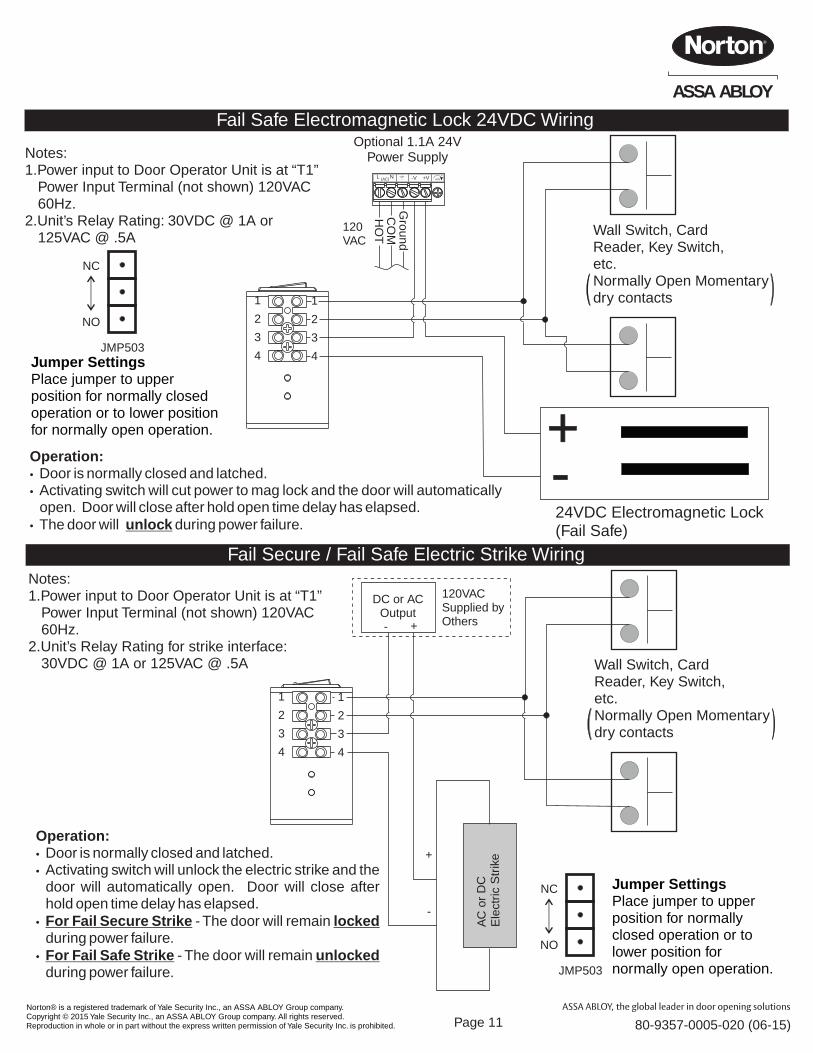
Fail Secure / Fail Safe Electric Strike Wiring
120VACSupplied byOthers- +
DC or ACOutput
AC
or
DC
Ele
ctric
Str
ike+
-
Wall Switch, CardReader, Key Switch,etc.Normally Open Momentary dry contacts
Notes:1.Power input to Door Operator Unit is at “T1”
Power Input Terminal (not shown) 120VAC 60Hz.
2.Unit’s Relay Rating for strike interface: 30VDC @ 1A or 125VAC @ .5A
Operation:· Door is normally closed and latched.· Activating switch will unlock the electric strike and the
door will automatically open. Door will close after hold open time delay has elapsed.
· For Fail Secure Strike - The door will remain locked during power failure.
· For Fail Safe Strike - The door will remain unlocked during power failure.
1
2
3
4
1
2
3
4
JMP503
NC
NO
Jumper SettingsPlace jumper to upper position for normally closed operation or to lower position for normally open operation.
Page 11
Fail Safe Electromagnetic Lock 24VDC Wiring
1
2
3
4
1
2
3
4
Wall Switch, CardReader, Key Switch,etc.Normally Open Momentary dry contacts
+-24VDC Electromagnetic Lock(Fail Safe)
Operation:· Door is normally closed and latched.· Activating switch will cut power to mag lock and the door will automatically
open. Door will close after hold open time delay has elapsed.· The door will unlock during power failure.
Notes:1.Power input to Door Operator Unit is at “T1”
Power Input Terminal (not shown) 120VAC 60Hz.
2.Unit’s Relay Rating: 30VDC @ 1A or 125VAC @ .5A
Jumper SettingsPlace jumper to upper position for normally closed operation or to lower position for normally open operation.
JMP503
NC
NO
120VAC
GroundC
OM
HO
T
L N(AC) -V +V ADJ+
Optional 1.1A 24V Power Supply
Norton® is a registered trademark of Yale Security Inc., an ASSA ABLOY Group company. Copyright © 2015 Yale Security Inc., an ASSA ABLOY Group company. All rights reserved. Reproduction in whole or in part without the express written permission of Yale Security Inc. is prohibited.
ASSA ABLOY
80-9357-0005-020 ( )06-15Page 12
Troubleshooting
Red LEDBlue LED
Antenna Wire
Learnw/o DelayButton
DelayPotentiometer(Time Adjustment)
Learn w/Delay Button
DIP Switch
TerminalStrip
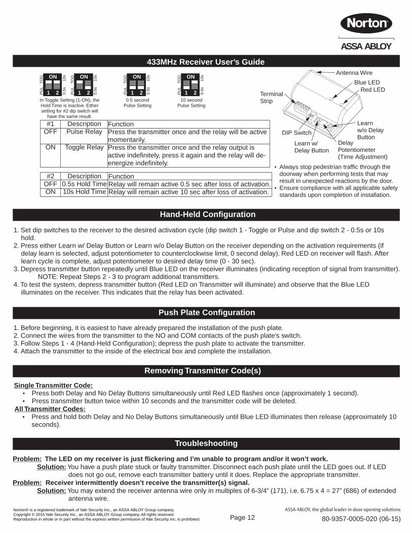
Problem: The LED on my receiver is just flickering and I’m unable to program and/or it won’t work.Solution: You have a push plate stuck or faulty transmitter. Disconnect each push plate until the LED goes out. If LED
does not go out, remove each transmitter battery until it does. Replace the appropriate transmitter.Problem: Receiver intermittently doesn’t receive the transmitter(s) signal.
Solution: You may extend the receiver antenna wire only in multiples of 6-3/4” (171), i.e. 6.75 x 4 = 27” (686) of extended antenna wire.
Removing Transmitter Code(s)
Single Transmitter Code:Ÿ Press both Delay and No Delay Buttons simultaneously until Red LED flashes once (approximately 1 second).Ÿ Press transmitter button twice within 10 seconds and the transmitter code will be deleted.
All Transmitter Codes:Ÿ Press and hold both Delay and No Delay Buttons simultaneously until Blue LED illuminates then release (approximately 10
seconds).
Push Plate Configuration
1. Before beginning, it is easiest to have already prepared the installation of the push plate.2. Connect the wires from the transmitter to the NO and COM contacts of the push plate’s switch.3. Follow Steps 1 - 4 (Hand-Held Configuration); depress the push plate to activate the transmitter.4. Attach the transmitter to the inside of the electrical box and complete the installation.
Hand-Held Configuration
1. Set dip switches to the receiver to the desired activation cycle (dip switch 1 - Toggle or Pulse and dip switch 2 - 0.5s or 10s hold.
2. Press either Learn w/ Delay Button or Learn w/o Delay Button on the receiver depending on the activation requirements (if delay learn is selected, adjust potentiometer to counterclockwise limit, 0 second delay). Red LED on receiver will flash. After learn cycle is complete, adjust potentiometer to desired delay time (0 - 30 sec).
3. Depress transmitter button repeatedly until Blue LED on the receiver illuminates (indicating reception of signal from transmitter). NOTE: Repeat Steps 2 - 3 to program additional transmitters.
4. To test the system, depress transmitter button (Red LED on Transmitter will illuminate) and observe that the Blue LED illuminates on the receiver. This indicates that the relay has been activated.
433MHz Receiver User’s Guide
#2OFFON
Description0.5s Hold Time10s Hold Time
FunctionRelay will remain active 0.5 sec after loss of activation.Relay will remain active 10 sec after loss of activation.
#1OFF
ON
DescriptionPulse Relay
Toggle Relay
FunctionPress the transmitter once and the relay will be active momentarily.Press the transmitter once and the relay output is active indefinitely, press it again and the relay will de-energize indefinitely.
ON
1 2PU
L T
OG
0.5s
1
0s ON
1 2PU
L T
OG
0.5s
1
0sIn Toggle Setting (1-ON), the Hold Time is inactive. Either setting for #2 dip switch will
have the same result.
ON
1 2PU
L T
OG
0.5s
1
0s
0.5 second Pulse Setting
ON
1 2PU
L T
OG
0.5s
1
0s
10 second Pulse Setting
ŸAlways stop pedestrian traffic through the doorway when performing tests that may result in unexpected reactions by the door.
ŸEnsure compliance with all applicable safety standards upon completion of installation.

Norton® is a registered trademark of Yale Security Inc., an ASSA ABLOY Group company. Copyright © 2015 Yale Security Inc., an ASSA ABLOY Group company. All rights reserved. Reproduction in whole or in part without the express written permission of Yale Security Inc. is prohibited.
ASSA ABLOY
80-9357-0005-020 ( )06-15Page 13
This PageLeft Blank
Norton® is a registered trademark of Yale Security Inc., an ASSA ABLOY Group company. Copyright © 2015 Yale Security Inc., an ASSA ABLOY Group company. All rights reserved. Reproduction in whole or in part without the express written permission of Yale Security Inc. is prohibited.
ASSA ABLOY
80-9357-0005-020 ( )06-15Page 14
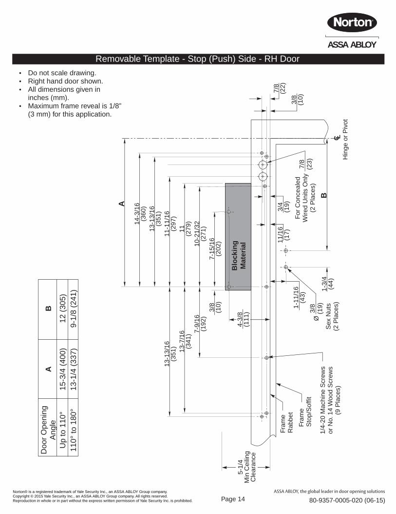
Removable Template - Stop (Push) Side - RH Door
Ÿ Do not scale drawing.Ÿ Right hand door shown.Ÿ All dimensions given in
inches (mm).Ÿ Maximum frame reveal is 1/8”
(3 mm) for this application.
Blo
ckin
gM
ater
ial
7-15
/16
(202
)10-2
1/32
(271
)
11(2
79)
11-1
1/16
(297
)
13-1
3/16
(351
)
14-3
/16
(360
)A
3/8
(10)
7-9/
16(1
92)
13-7
/16
(341
)
13-1
3/16
(351
)
B1-
3/4
(44)
3/8
(10)
7/8
(22)
3/4
(19)
4-3/
8(1
11)
1-11
/16
(43)
7/8
(23)
For
Con
ceal
edW
ired
Uni
ts O
nly
(2 P
lace
s)
C LH
inge
or
Piv
ot
Fram
eS
top/
Sof
fit
Fram
eR
abbe
t
3/8
(19)
1/4-
20 M
achi
ne S
crew
sor
No.
14
Woo
d S
crew
s(9
Pla
ces)
Ø
Sex
Nut
s(2
Pla
ces)
5-1/
4M
in C
eilin
gC
lear
ance
Doo
r O
peni
ngA
ngle
Up
to 1
10°
110°
to 1
80°
A
15-3
/4 (
400)
13-1
/4 (
337)
B
12 (
305)
9-1/
8 (2
41)
11/1
6(1
7)
Norton® is a registered trademark of Yale Security Inc., an ASSA ABLOY Group company. Copyright © 2015 Yale Security Inc., an ASSA ABLOY Group company. All rights reserved. Reproduction in whole or in part without the express written permission of Yale Security Inc. is prohibited.
ASSA ABLOY
80-9357-0005-020 ( )06-15Page 15
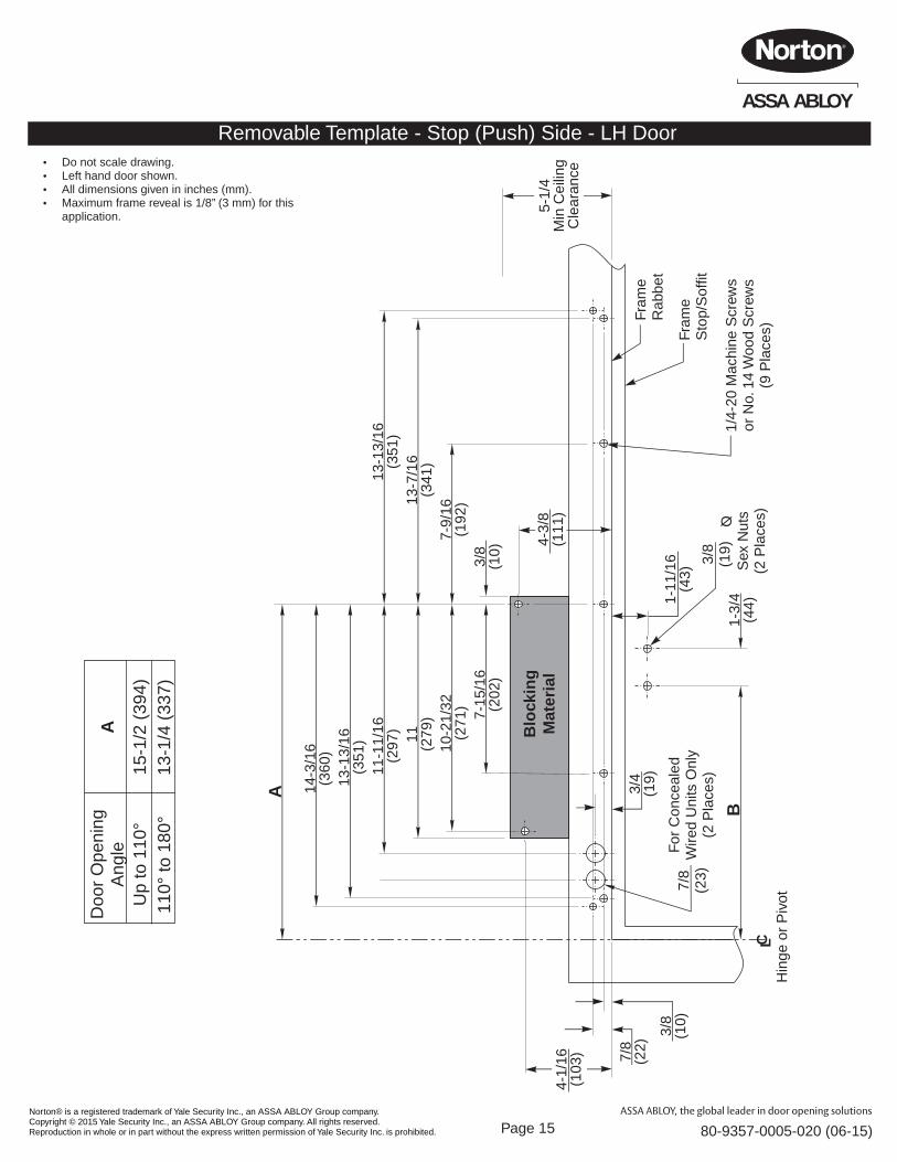
Removable Template - Stop (Push) Side - LH Door
Doo
r O
peni
ngA
ngle
Up
to 1
10°
110°
to 1
80°
A
15-1
/2 (
394)
13-1
/4 (
337)
Ÿ Do not scale drawing.Ÿ Left hand door shown.Ÿ All dimensions given in inches (mm).Ÿ Maximum frame reveal is 1/8” (3 mm) for this
application.
Blo
ckin
gM
ater
ial
7-15
/16
(202
)
10-2
1/32
(271
)
11(2
79)
11-1
1/16
(297
)
13-1
3/16
(351
)
14-3
/16
(360
)
A
3/8
(10)
7-9/
16(1
92)13
-7/1
6(3
41)
13-1
3/16
(351
)
B1-
3/4
(44)
4-1/
16(1
03)
3/8
(10)
7/8
(22)
3/4
(19)
4-3/
8(1
11)
1-11
/16
(43)
7/8
(23)
For
Con
ceal
edW
ired
Uni
ts O
nly
(2 P
lace
s)
C LH
inge
or
Piv
ot
Fram
eS
top/
Sof
fit
Fram
eR
abbe
t
3/8
(19)
1/4-
20 M
achi
ne S
crew
sor
No.
14
Woo
d S
crew
s(9
Pla
ces)
Ø
Sex
Nut
s(2
Pla
ces)
5-1/
4M
in C
eilin
gC
lear
ance

Norton® is a registered trademark of Yale Security Inc., an ASSA ABLOY Group company. Copyright © 2015 Yale Security Inc., an ASSA ABLOY Group company. All rights reserved. Reproduction in whole or in part without the express written permission of Yale Security Inc. is prohibited.
ASSA ABLOY
80-9357-0005-020 ( )06-15Page 16
3000 Highway 74 East • Monroe, NC 28112Tel: (800)438-1951 x4706 • Fax: (800)-338-0965
www.nor tondoorcontrols.com
ASSA ABLOY
This PageLeft Blank