
ASCET V6.2 Icon Reference Guide - ETAS · ASCET V6.2 - Icon Reference Guide 5 ETASIntroduction 1...
44
ASCET V6.2 Icon Reference Guide
Transcript of ASCET V6.2 Icon Reference Guide - ETAS · ASCET V6.2 - Icon Reference Guide 5 ETASIntroduction 1...
ASCET V6.2Icon Reference Guide
2
Copyright
The data in this document may not be altered or amended without special noti-fication from ETAS GmbH. ETAS GmbH undertakes no further obligation in rela-tion to this document. The software described in it can only be used if thecustomer is in possession of a general license agreement or single license. Usingand copying is only allowed in concurrence with the specifications stipulated inthe contract.
Under no circumstances may any part of this document be copied, reproduced,transmitted, stored in a retrieval system or translated into another languagewithout the express written permission of ETAS GmbH.
© Copyright 2013 ETAS GmbH, Stuttgart
The names and designations used in this document are trademarks or brandsbelonging to the respective owners.
Document EC010015 V6.2 R01 EN - 05.2013
Contents
ETAS Contents
1 Introduction . . . . . . . . . . . . . . . . . . . . . . . . . . . . . . . . . . . . . . . . . . . . . . . . . . . . . . 51.1 Safety Advice . . . . . . . . . . . . . . . . . . . . . . . . . . . . . . . . . . . . . . . . . . . . . . . . 5
1.1.1 Correct Use . . . . . . . . . . . . . . . . . . . . . . . . . . . . . . . . . . . . . . . . . . . 51.1.2 Labeling of Safety Instructions . . . . . . . . . . . . . . . . . . . . . . . . . . . . . 51.1.3 Demands on the Technical State of the Product. . . . . . . . . . . . . . . . 5
1.2 Manual Structure . . . . . . . . . . . . . . . . . . . . . . . . . . . . . . . . . . . . . . . . . . . . . 61.3 Typographic Conventions . . . . . . . . . . . . . . . . . . . . . . . . . . . . . . . . . . . . . . . 6
2 Operators in Block Diagrams . . . . . . . . . . . . . . . . . . . . . . . . . . . . . . . . . . . . . . . . . . 72.1 Arithmetic Operators . . . . . . . . . . . . . . . . . . . . . . . . . . . . . . . . . . . . . . . . . . 72.2 Comparison Operators . . . . . . . . . . . . . . . . . . . . . . . . . . . . . . . . . . . . . . . . . 82.3 Logical Operators . . . . . . . . . . . . . . . . . . . . . . . . . . . . . . . . . . . . . . . . . . . . . 92.4 Multiplex Operator . . . . . . . . . . . . . . . . . . . . . . . . . . . . . . . . . . . . . . . . . . . . 92.5 Case Operator . . . . . . . . . . . . . . . . . . . . . . . . . . . . . . . . . . . . . . . . . . . . . . . 92.6 Miscellaneous Operators . . . . . . . . . . . . . . . . . . . . . . . . . . . . . . . . . . . . . . . 10
3 Control Flow Elements in Block Diagrams . . . . . . . . . . . . . . . . . . . . . . . . . . . . . . . 133.1 If...Then . . . . . . . . . . . . . . . . . . . . . . . . . . . . . . . . . . . . . . . . . . . . . . . . . . . 133.2 If...Then...Else . . . . . . . . . . . . . . . . . . . . . . . . . . . . . . . . . . . . . . . . . . . . . . . 133.3 Switch . . . . . . . . . . . . . . . . . . . . . . . . . . . . . . . . . . . . . . . . . . . . . . . . . . . . 143.4 While . . . . . . . . . . . . . . . . . . . . . . . . . . . . . . . . . . . . . . . . . . . . . . . . . . . . . 143.5 Break . . . . . . . . . . . . . . . . . . . . . . . . . . . . . . . . . . . . . . . . . . . . . . . . . . . . . 15
4 Elements in Block Diagrams . . . . . . . . . . . . . . . . . . . . . . . . . . . . . . . . . . . . . . . . . 174.1 Scalar Elements . . . . . . . . . . . . . . . . . . . . . . . . . . . . . . . . . . . . . . . . . . . . . . 17
4.1.1 Variables . . . . . . . . . . . . . . . . . . . . . . . . . . . . . . . . . . . . . . . . . . . . 174.1.2 Parameters . . . . . . . . . . . . . . . . . . . . . . . . . . . . . . . . . . . . . . . . . . 184.1.3 Real-Time Elements . . . . . . . . . . . . . . . . . . . . . . . . . . . . . . . . . . . . 18
Messages . . . . . . . . . . . . . . . . . . . . . . . . . . . . . . . . . . . . . . . . . . . 18Resources . . . . . . . . . . . . . . . . . . . . . . . . . . . . . . . . . . . . . . . . . . . 19
ASCET V6.2 - Icon Reference Guide 3
4
Contents ETAS
dT Parameter. . . . . . . . . . . . . . . . . . . . . . . . . . . . . . . . . . . . . . . . . 204.1.4 Literals . . . . . . . . . . . . . . . . . . . . . . . . . . . . . . . . . . . . . . . . . . . . . 204.1.5 Constants and System Constants. . . . . . . . . . . . . . . . . . . . . . . . . . 20
4.2 Composite Elements . . . . . . . . . . . . . . . . . . . . . . . . . . . . . . . . . . . . . . . . . . 214.2.1 Arrays . . . . . . . . . . . . . . . . . . . . . . . . . . . . . . . . . . . . . . . . . . . . . . 214.2.2 Matrices . . . . . . . . . . . . . . . . . . . . . . . . . . . . . . . . . . . . . . . . . . . . 224.2.3 Characteristic Lines and Maps . . . . . . . . . . . . . . . . . . . . . . . . . . . . 23
Characteristic Lines . . . . . . . . . . . . . . . . . . . . . . . . . . . . . . . . . . . . 23Characteristic Maps . . . . . . . . . . . . . . . . . . . . . . . . . . . . . . . . . . . . 24
4.3 Complex Elements (Included Components) . . . . . . . . . . . . . . . . . . . . . . . . . 264.4 Signature Elements . . . . . . . . . . . . . . . . . . . . . . . . . . . . . . . . . . . . . . . . . . . 26
4.4.1 Method Signature Elements. . . . . . . . . . . . . . . . . . . . . . . . . . . . . . 26Method Arguments . . . . . . . . . . . . . . . . . . . . . . . . . . . . . . . . . . . 27Local Variables (Method) . . . . . . . . . . . . . . . . . . . . . . . . . . . . . . . . 28Return Value . . . . . . . . . . . . . . . . . . . . . . . . . . . . . . . . . . . . . . . . . 28
4.4.2 Process Signature Elements . . . . . . . . . . . . . . . . . . . . . . . . . . . . . . 294.5 Miscellaneous Elements . . . . . . . . . . . . . . . . . . . . . . . . . . . . . . . . . . . . . . . 29
4.5.1 Implementation Casts . . . . . . . . . . . . . . . . . . . . . . . . . . . . . . . . . . 294.5.2 Hierarchies . . . . . . . . . . . . . . . . . . . . . . . . . . . . . . . . . . . . . . . . . . 304.5.3 Self . . . . . . . . . . . . . . . . . . . . . . . . . . . . . . . . . . . . . . . . . . . . . . . . 304.5.4 Comments . . . . . . . . . . . . . . . . . . . . . . . . . . . . . . . . . . . . . . . . . . 31
5 Miscellaneous Icons . . . . . . . . . . . . . . . . . . . . . . . . . . . . . . . . . . . . . . . . . . . . . . . 335.1 Scope Icons . . . . . . . . . . . . . . . . . . . . . . . . . . . . . . . . . . . . . . . . . . . . . . . . 335.2 Icons for Properties . . . . . . . . . . . . . . . . . . . . . . . . . . . . . . . . . . . . . . . . . . . 345.3 Icons in the "Tree" Pane . . . . . . . . . . . . . . . . . . . . . . . . . . . . . . . . . . . . . . . 355.4 Icons in the "General" Toolbar . . . . . . . . . . . . . . . . . . . . . . . . . . . . . . . . . . 365.5 Icons in Tab Labels . . . . . . . . . . . . . . . . . . . . . . . . . . . . . . . . . . . . . . . . . . . 37
6 ETAS Contact Addresses . . . . . . . . . . . . . . . . . . . . . . . . . . . . . . . . . . . . . . . . . . . . 39ETAS HQ . . . . . . . . . . . . . . . . . . . . . . . . . . . . . . . . . . . . . . . . . . . . 39ETAS Subsidiaries and Technical Support . . . . . . . . . . . . . . . . . . . . 39
Index . . . . . . . . . . . . . . . . . . . . . . . . . . . . . . . . . . . . . . . . . . . . . . . . . . . . . . . . . . 41
ASCET V6.2 - Icon Reference Guide
ETASIntroduction
1 Introduction
ASCET provides an innovative solution for the functional and software develop-ment of modern embedded software systems. ASCET supports every step of thedevelopment process with a new approach to modelling, code generation andsimulation, thus making higher quality, shorter innovation cycles and cost reduc-tions a reality.
This manual lists the icons and symbols that appear in classes and modules spec-ified as ASCET block diagrams.
1.1 Safety Advice
Please adhere to the Product Liability Disclaimer (ETAS Safety Advice) and to thefollowing safety instructions to avoid injury to yourself and others as well as dam-age to the device.
1.1.1 Correct Use
ETAS GmbH cannot be made liable for damage which is caused by incorrect useand not adhering to the safety instructions.
1.1.2 Labeling of Safety Instructions
The safety instructions contained in this manual are shown with the standarddanger symbol shown below:
The following safety instructions are used. They provide extremely importantinformation. Read this information carefully.
1.1.3 Demands on the Technical State of the Product
The following special requirements are made to ensure safe operation:
• Take all information on environmental conditions into consideration before setup and operation (see the documentation of your computer, hardware, etc.).
WARNING!
Indicates a possible medium-risk danger which could lead to serious or even fatal injuries if not avoided.
CAUTION!
Indicates a low-risk danger which could result in minor or less serious injury or damage if not avoided.
NOTICE
Indicates behavior which could result in damage to property.
ASCET V6.2 - Icon Reference Guide 5
6
Introduction ETAS
Further safety advice is given in the ASCET V6.2 safety manual (ASCET SafetyManual.pdf) available on your installation disk, in the ETASManuals\ASCETV6.2 folder on your computer or in the download center of the ETAS web site.
1.2 Manual Structure
The ASCET "Block Diagram Icon Reference" manual contains the followingchapters:
• "Introduction" (this chapter)
This chapter contains general information such as documentation conven-tions.
• "Operators in Block Diagrams"
This chapter lists all block diagram operators and their icons.
• "Control Flow Elements in Block Diagrams"
This chapter lists all control flow elements and their icons.
• "Elements in Block Diagrams"
This chapter lists all block diagram elements and their icons.
• "Miscellaneous Icons"
This chapter lists the remaining icons and their meaning.
1.3 Typographic Conventions
The following typographic conventions are used in this manual:
Important notes for the users are presented as follows:
Select File Open. Menu commands are shown in blue bold-face.
Click OK. Names of buttons and options are shown in blue boldface.
Press <ENTER>. Keyboard commands are shown in angled brackets and CAPITALS.
The "Open File" dialog window opens.
Names of program windows, dialog windows, fields, etc. are shown in quotation marks.
Select the file setup.exe. Text in drop-down lists on the screen, pro-gram code, as well as path- and file names are shown in the Courier font.
A distribution is always a one-dimensional table of sample points.
General emphasis and new terms are set in italics.
The OSEK group (see http://www.osekvdx.org/) has developed certain standards.
Links to internet documents are set in blue, underlined font.
Note
Important note for users.
ASCET V6.2 - Icon Reference Guide
ETAS Operators in Block Diagrams
2 Operators in Block Diagrams
This chapter lists the operators available in ASCET block diagrams.
• arithmetic operators (section 2.1 on page 7)
• comparison operators (section 2.2 on page 8)
• logical operators (section 2.3 on page 9)
• multiplex operator (section 2.4 on page 9)
• case operator (section 2.5 on page 9)
• miscelllaneous operators (section 2.6 on page 10)
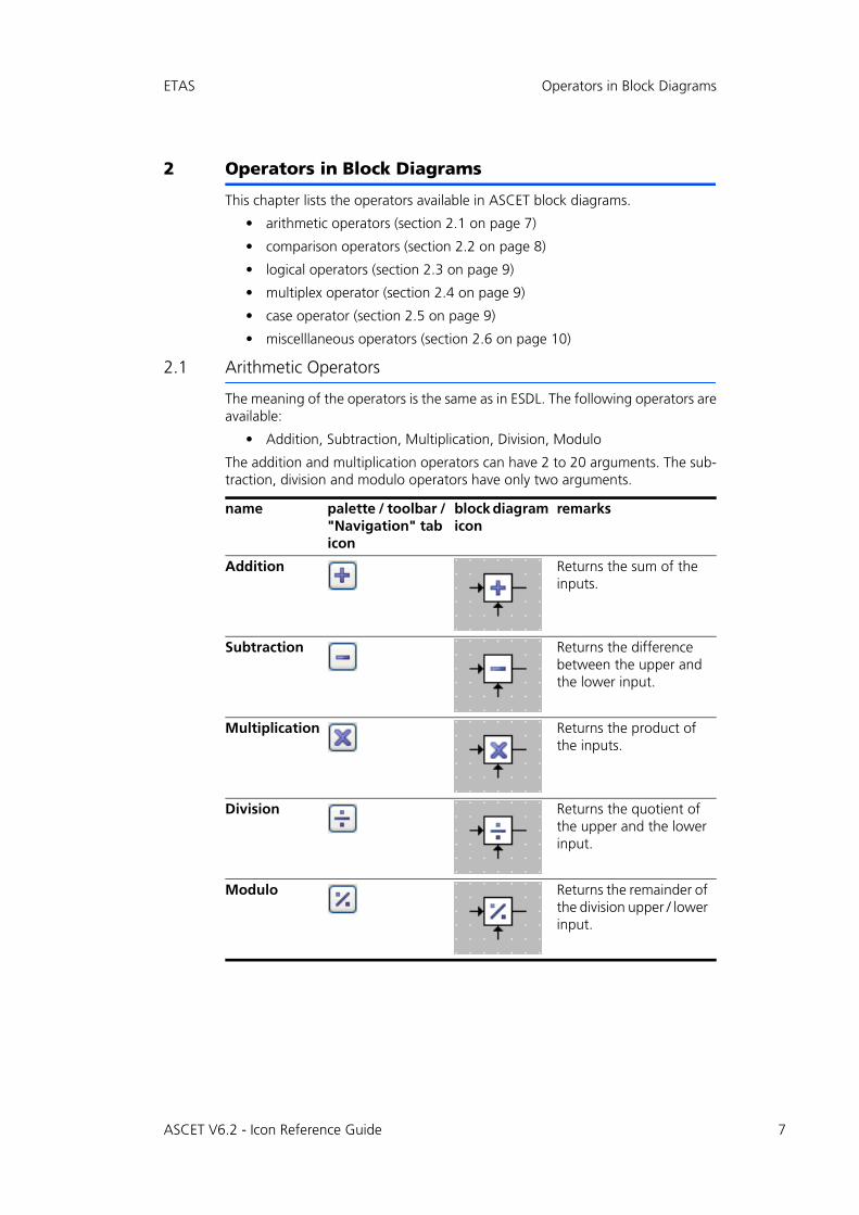
2.1 Arithmetic Operators
The meaning of the operators is the same as in ESDL. The following operators areavailable:
• Addition, Subtraction, Multiplication, Division, Modulo
The addition and multiplication operators can have 2 to 20 arguments. The sub-traction, division and modulo operators have only two arguments.
name palette / toolbar / "Navigation" tab icon
block diagram icon
remarks
Addition Returns the sum of the inputs.
Subtraction Returns the difference between the upper and the lower input.
Multiplication Returns the product of the inputs.
Division Returns the quotient of the upper and the lower input.
Modulo Returns the remainder of the division upper / lower input.
ASCET V6.2 - Icon Reference Guide 7
8
Operators in Block Diagrams ETAS
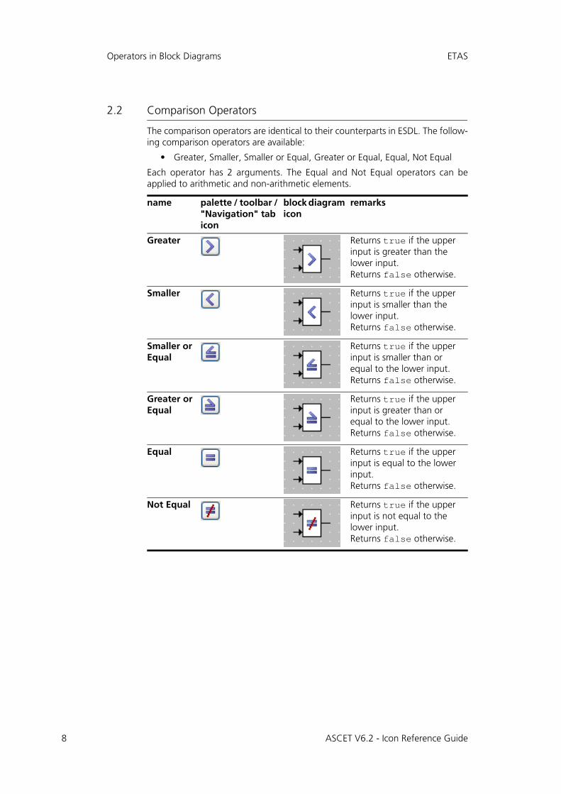
2.2 Comparison Operators
The comparison operators are identical to their counterparts in ESDL. The follow-ing comparison operators are available:
• Greater, Smaller, Smaller or Equal, Greater or Equal, Equal, Not Equal
Each operator has 2 arguments. The Equal and Not Equal operators can beapplied to arithmetic and non-arithmetic elements.
name palette / toolbar / "Navigation" tab icon
block diagram icon
remarks
Greater Returns true if the upper input is greater than the lower input. Returns false otherwise.
Smaller Returns true if the upper input is smaller than the lower input.Returns false otherwise.
Smaller or Equal
Returns true if the upper input is smaller than or equal to the lower input.Returns false otherwise.
Greater or Equal
Returns true if the upper input is greater than or equal to the lower input.Returns false otherwise.
Equal Returns true if the upper input is equal to the lower input.Returns false otherwise.
Not Equal Returns true if the upper input is not equal to the lower input.Returns false otherwise.
ASCET V6.2 - Icon Reference Guide
ETAS Operators in Block Diagrams
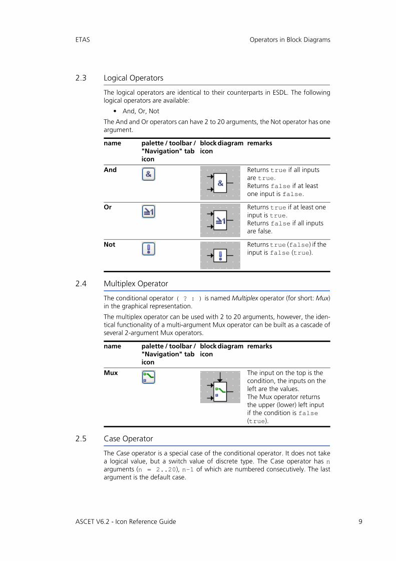
2.3 Logical Operators
The logical operators are identical to their counterparts in ESDL. The followinglogical operators are available:
• And, Or, Not
The And and Or operators can have 2 to 20 arguments, the Not operator has oneargument.
2.4 Multiplex Operator
The conditional operator ( ? : ) is named Multiplex operator (for short: Mux)in the graphical representation.
The multiplex operator can be used with 2 to 20 arguments, however, the iden-tical functionality of a multi-argument Mux operator can be built as a cascade ofseveral 2-argument Mux operators.
2.5 Case Operator
The Case operator is a special case of the conditional operator. It does not takea logical value, but a switch value of discrete type. The Case operator has narguments (n = 2..20), n-1 of which are numbered consecutively. The lastargument is the default case.
name palette / toolbar / "Navigation" tab icon
block diagram icon
remarks
And Returns true if all inputs are true.Returns false if at least one input is false.
Or Returns true if at least one input is true.Returns false if all inputs are false.
Not Returns true (false) if the input is false (true).
name palette / toolbar / "Navigation" tab icon
block diagram icon
remarks
Mux The input on the top is the condition, the inputs on the left are the values.The Mux operator returns the upper (lower) left input if the condition is false (true).
ASCET V6.2 - Icon Reference Guide 9
10
Operators in Block Diagrams ETAS
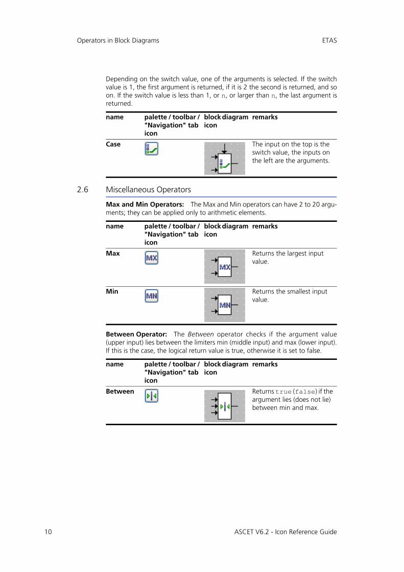
Depending on the switch value, one of the arguments is selected. If the switchvalue is 1, the first argument is returned, if it is 2 the second is returned, and soon. If the switch value is less than 1, or n, or larger than n, the last argument isreturned.
2.6 Miscellaneous Operators
Max and Min Operators: The Max and Min operators can have 2 to 20 argu-ments; they can be applied only to arithmetic elements.
Between Operator: The Between operator checks if the argument value(upper input) lies between the limiters min (middle input) and max (lower input).If this is the case, the logical return value is true, otherwise it is set to false.
name palette / toolbar / "Navigation" tab icon
block diagram icon
remarks
Case The input on the top is the switch value, the inputs on the left are the arguments.
name palette / toolbar / "Navigation" tab icon
block diagram icon
remarks
Max Returns the largest input value.
Min Returns the smallest input value.
name palette / toolbar / "Navigation" tab icon
block diagram icon
remarks
Between Returns true (false) if the argument lies (does not lie) between min and max.
ASCET V6.2 - Icon Reference Guide
ETAS Operators in Block Diagrams
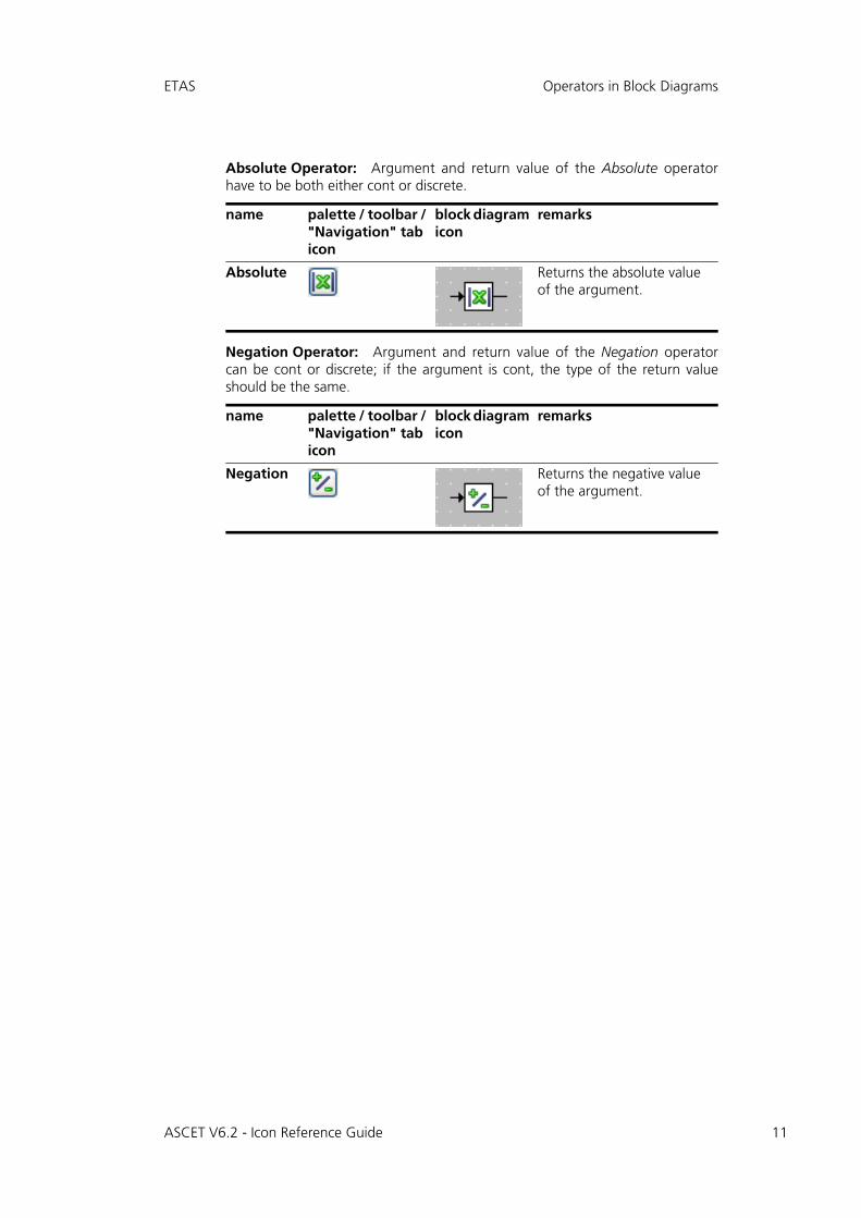
Absolute Operator: Argument and return value of the Absolute operatorhave to be both either cont or discrete.
Negation Operator: Argument and return value of the Negation operatorcan be cont or discrete; if the argument is cont, the type of the return valueshould be the same.
name palette / toolbar / "Navigation" tab icon
block diagram icon
remarks
Absolute Returns the absolute value of the argument.
name palette / toolbar / "Navigation" tab icon
block diagram icon
remarks
Negation Returns the negative value of the argument.
ASCET V6.2 - Icon Reference Guide 11
12
Operators in Block Diagrams ETAS
ASCET V6.2 - Icon Reference Guide
ETAS Control Flow Elements in Block Diagrams
3 Control Flow Elements in Block Diagrams
This chapter lists the control flow elements available in ASCET block diagrams.
The following control flow statements are available in block diagrams:
• If...Then (section 3.1 on page 13)
• If...Then...Else (section 3.2 on page 13)
• Switch (section 3.3 on page 14)
• While (section 3.4 on page 14)
• Break Statement (section 3.5 on page 15)
All control flow statements except Break evaluate a logical expression and,depending on the result, activate a control flow branch which may contain sev-eral statements. The statements represented by sequence calls are connected tothe control flow by connectors.
The Break statement can be used to exit immediately from each of the othercontrol flow elements and return to another enclosing statement or to theremainder of the model.
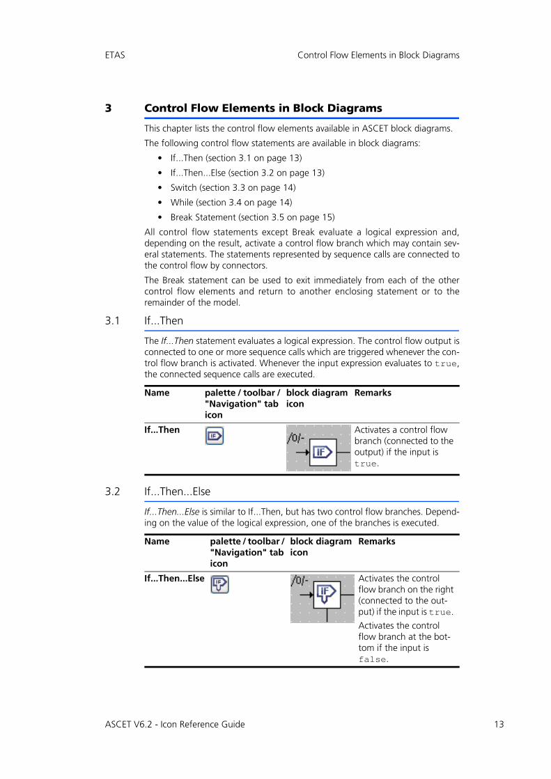
3.1 If...Then
The If...Then statement evaluates a logical expression. The control flow output isconnected to one or more sequence calls which are triggered whenever the con-trol flow branch is activated. Whenever the input expression evaluates to true,the connected sequence calls are executed.
3.2 If...Then...Else
If...Then...Else is similar to If...Then, but has two control flow branches. Depend-ing on the value of the logical expression, one of the branches is executed.
Name palette / toolbar / "Navigation" tab icon
block diagram icon
Remarks
If...Then Activates a control flow branch (connected to the output) if the input is true.
Name palette / toolbar / "Navigation" tab icon
block diagram icon
Remarks
If...Then...Else Activates the control flow branch on the right (connected to the out-put) if the input is true.
Activates the control flow branch at the bot-tom if the input is false.
ASCET V6.2 - Icon Reference Guide 13
14
Control Flow Elements in Block Diagrams ETAS
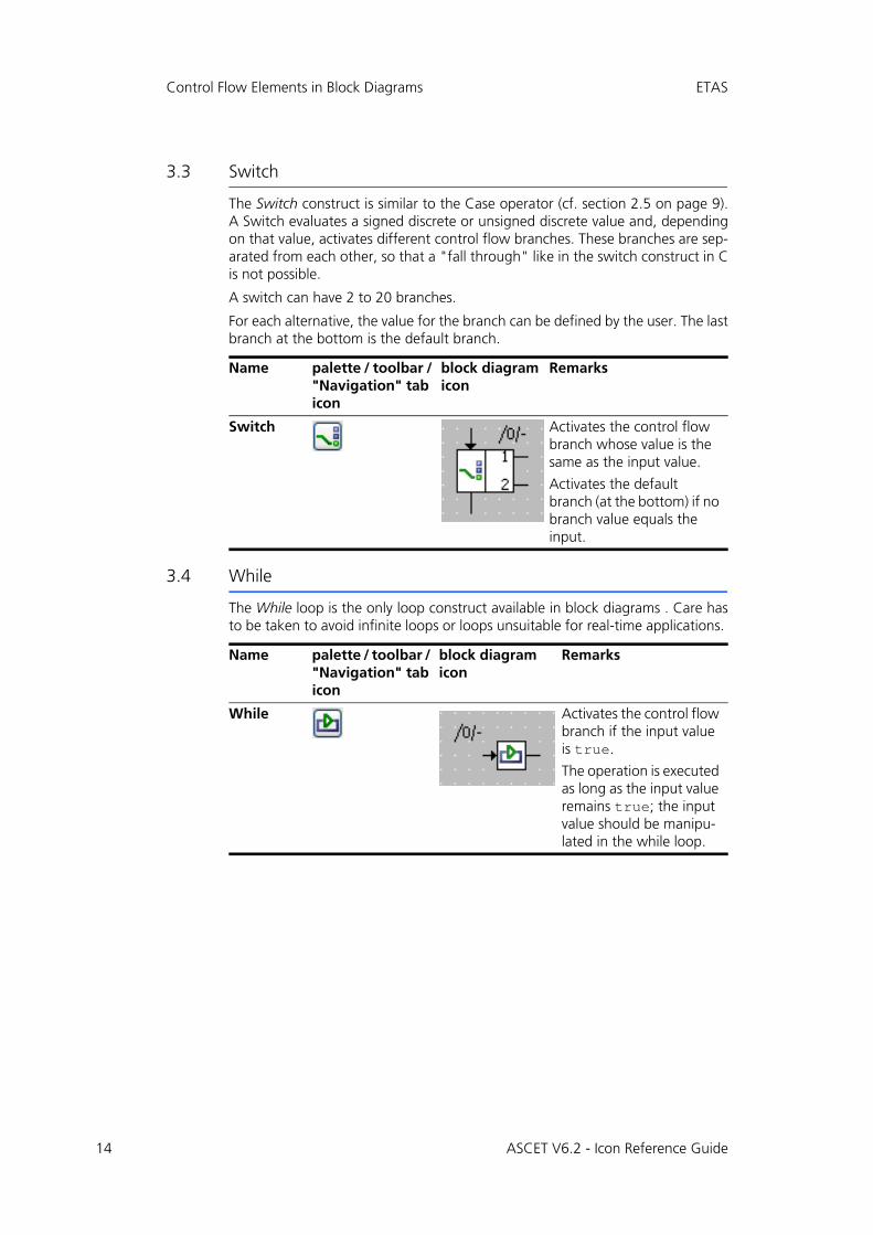
3.3 Switch
The Switch construct is similar to the Case operator (cf. section 2.5 on page 9).A Switch evaluates a signed discrete or unsigned discrete value and, dependingon that value, activates different control flow branches. These branches are sep-arated from each other, so that a "fall through" like in the switch construct in Cis not possible.
A switch can have 2 to 20 branches.
For each alternative, the value for the branch can be defined by the user. The lastbranch at the bottom is the default branch.
3.4 While
The While loop is the only loop construct available in block diagrams . Care hasto be taken to avoid infinite loops or loops unsuitable for real-time applications.
Name palette / toolbar / "Navigation" tab icon
block diagram icon
Remarks
Switch Activates the control flow branch whose value is the same as the input value.
Activates the default branch (at the bottom) if no branch value equals the input.
Name palette / toolbar / "Navigation" tab icon
block diagram icon
Remarks
While Activates the control flow branch if the input value is true.
The operation is executed as long as the input value remains true; the input value should be manipu-lated in the while loop.
ASCET V6.2 - Icon Reference Guide
ETAS Control Flow Elements in Block Diagrams
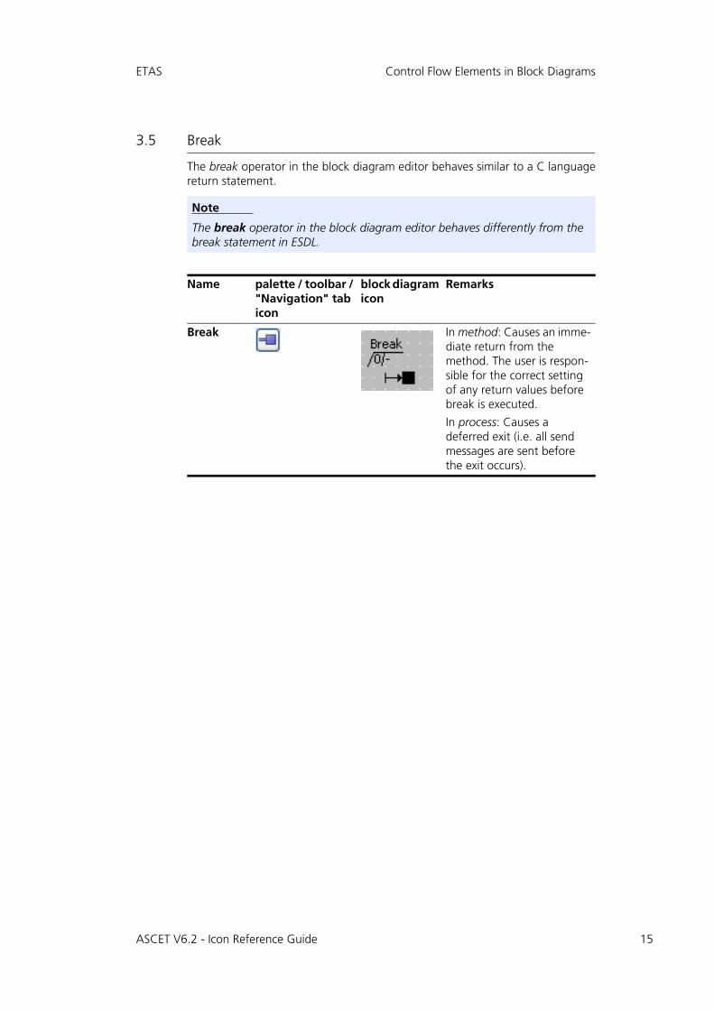
3.5 Break
The break operator in the block diagram editor behaves similar to a C languagereturn statement.
Note
The break operator in the block diagram editor behaves differently from the break statement in ESDL.
Name palette / toolbar / "Navigation" tab icon
block diagram icon
Remarks
Break In method: Causes an imme-diate return from the method. The user is respon-sible for the correct setting of any return values before break is executed.
In process: Causes a deferred exit (i.e. all send messages are sent before the exit occurs).
ASCET V6.2 - Icon Reference Guide 15
16
Control Flow Elements in Block Diagrams ETAS
ASCET V6.2 - Icon Reference Guide
ETAS Elements in Block Diagrams
4 Elements in Block Diagrams
This chapter lists the elements available in ASCET block diagrams.
• section 4.1 "Scalar Elements" on page 17
• section 4.2 "Composite Elements" on page 21
• section 4.3 "Complex Elements (Included Components)" on page 26
• section 4.4 "Signature Elements" on page 26
• section 4.5 "Miscellaneous Elements" on page 29
4.1 Scalar Elements
Several scalar elements are available in ASCET block diagrams:
• variables (section 4.1.1 on page 17)
• parameters (section 4.1.2 on page 18)
• real-time elements (section 4.1.3 on page 18)
• literals (section 4.1.4 on page 20)
• constants and system constants (section 4.1.5 on page 20)
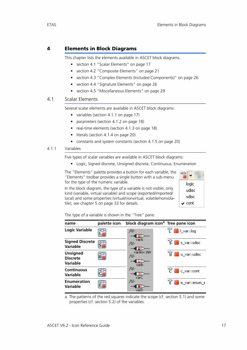
4.1.1 Variables
Five types of scalar variables are available in ASCET block diagrams:
• Logic, Signed discrete, Unsigned discrete, Continuous, Enumeration
The type of a variable is shown in the "Tree" pane.
The "Elements" palette provides a button for each variable, the "Elements" toolbar provides a single button with a sub-menu for the type of the numeric variable.
In the block diagram, the type of a variable is not visible, only kind (variable, virtual variable) and scope (exported/imported/local) and some properties (virtual/nonvirtual, volatile/nonvola-tile); see chapter 5 on page 33 for details.
name palette icon block diagram icona
a. The patterns of the red squares indicate the scope (cf. section 5.1) and some properties (cf. section 5.2) of the variables.
Tree pane icon
Logic Variable
Signed Discrete Variable
Unsigned Discrete Variable
Continuous Variable
Enumeration Variable
ASCET V6.2 - Icon Reference Guide 17
18
Elements in Block Diagrams ETAS
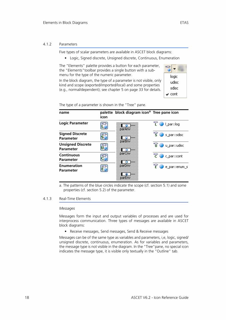
4.1.2 Parameters
Five types of scalar parameters are available in ASCET block diagrams:
• Logic, Signed discrete, Unsigned discrete, Continuous, Enumeration
The type of a parameter is shown in the "Tree" pane.
4.1.3 Real-Time Elements
Messages
Messages form the input and output variables of processes and are used forinterprocess communication. Three types of messages are available in ASCETblock diagrams:
• Receive messages, Send messages,Send & Receive messages
Messages can be of the same type as variables and parameters, i,e, logic, signed/unsigned discrete, continuous, enumeration. As for variables and parameters,the message type is not visible in the diagram. In the "Tree"pane, no special iconindicates the message type, it is visible only textually in the "Outline" tab.
The "Elements" palette provides a button for each parameter, the "Elements"toolbar provides a single button with a sub-menu for the type of the numeric parameter.
In the block diagram, the type of a parameter is not visible, only kind and scope (exported/imported/local) and some properties (e.g., normal/dependent); see chapter 5 on page 33 for details.
name palette icon
block diagram icona
a. The patterns of the blue circles indicate the scope (cf. section 5.1) and some properties (cf. section 5.2) of the parameter.
Tree pane icon
Logic Parameter
Signed Discrete Parameter
Unsigned Discrete Parameter
Continuous Parameter
Enumeration Parameter
ASCET V6.2 - Icon Reference Guide
ETAS Elements in Block Diagrams
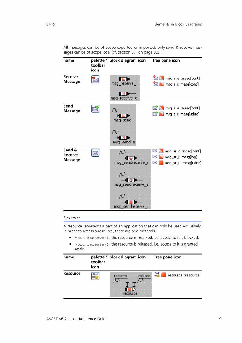
All messages can be of scope exported or imported, only send & receive mes-sages can be of scope local (cf. section 5.1 on page 33).
Resources
A resource represents a part of an application that can only be used exclusively.In order to access a resource, there are two methods:
• void reserve(): the resource is reserved, i.e. access to it is blocked.
• void release(): the resource is released, i.e. access to it is granted again.
name palette / toolbar icon
block diagram icon Tree pane icon
Receive Message
Send Message
Send & Receive Message
name palette / toolbar icon
block diagram icon Tree pane icon
Resource
ASCET V6.2 - Icon Reference Guide 19
20
Elements in Block Diagrams ETAS
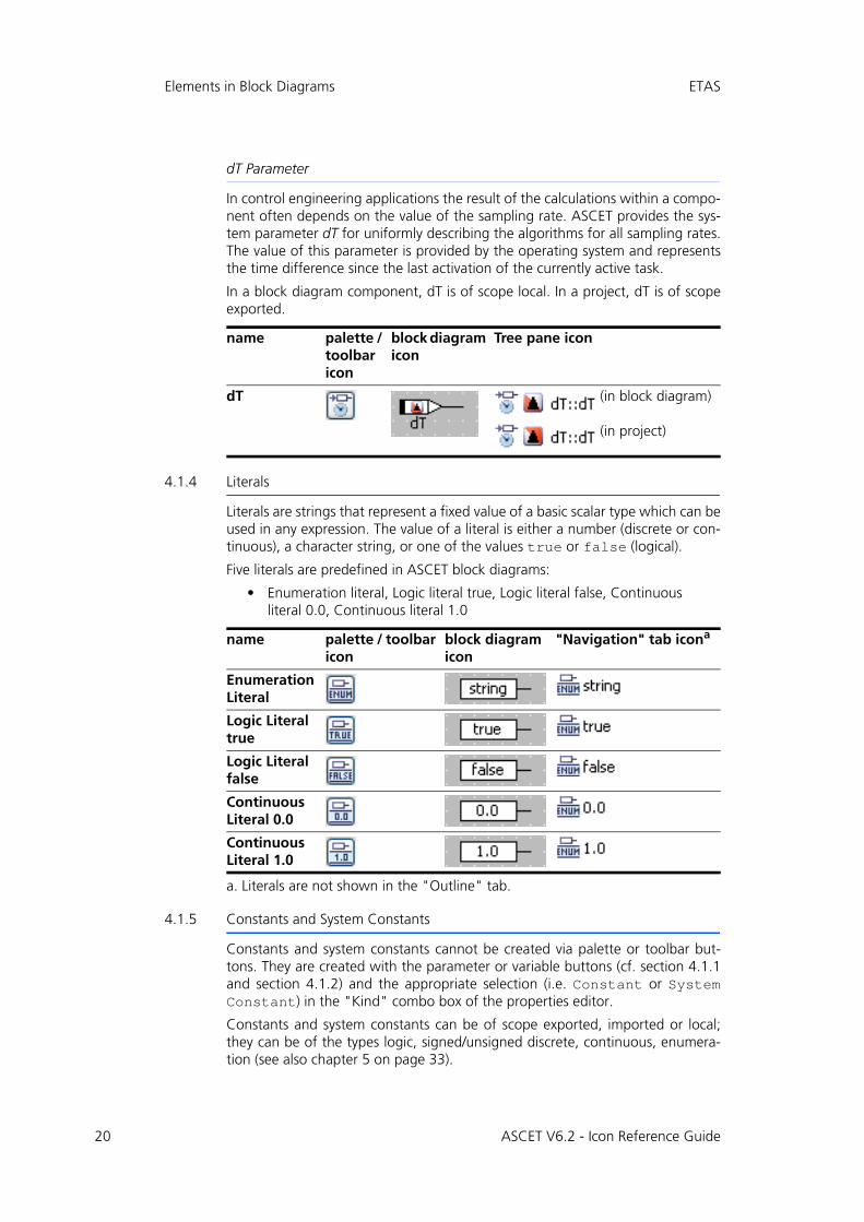
dT Parameter
In control engineering applications the result of the calculations within a compo-nent often depends on the value of the sampling rate. ASCET provides the sys-tem parameter dT for uniformly describing the algorithms for all sampling rates.The value of this parameter is provided by the operating system and representsthe time difference since the last activation of the currently active task.
In a block diagram component, dT is of scope local. In a project, dT is of scopeexported.
4.1.4 Literals
Literals are strings that represent a fixed value of a basic scalar type which can beused in any expression. The value of a literal is either a number (discrete or con-tinuous), a character string, or one of the values true or false (logical).
Five literals are predefined in ASCET block diagrams:
• Enumeration literal, Logic literal true, Logic literal false, Continuous literal 0.0, Continuous literal 1.0
4.1.5 Constants and System Constants
Constants and system constants cannot be created via palette or toolbar but-tons. They are created with the parameter or variable buttons (cf. section 4.1.1and section 4.1.2) and the appropriate selection (i.e. Constant or SystemConstant) in the "Kind" combo box of the properties editor.
Constants and system constants can be of scope exported, imported or local;they can be of the types logic, signed/unsigned discrete, continuous, enumera-tion (see also chapter 5 on page 33).
name palette / toolbar icon
block diagram icon
Tree pane icon
dT (in block diagram)
(in project)
name palette / toolbar icon
block diagram icon
"Navigation" tab icona
a. Literals are not shown in the "Outline" tab.
Enumeration Literal
Logic Literal true
Logic Literal false
Continuous Literal 0.0
Continuous Literal 1.0
ASCET V6.2 - Icon Reference Guide
ETAS Elements in Block Diagrams
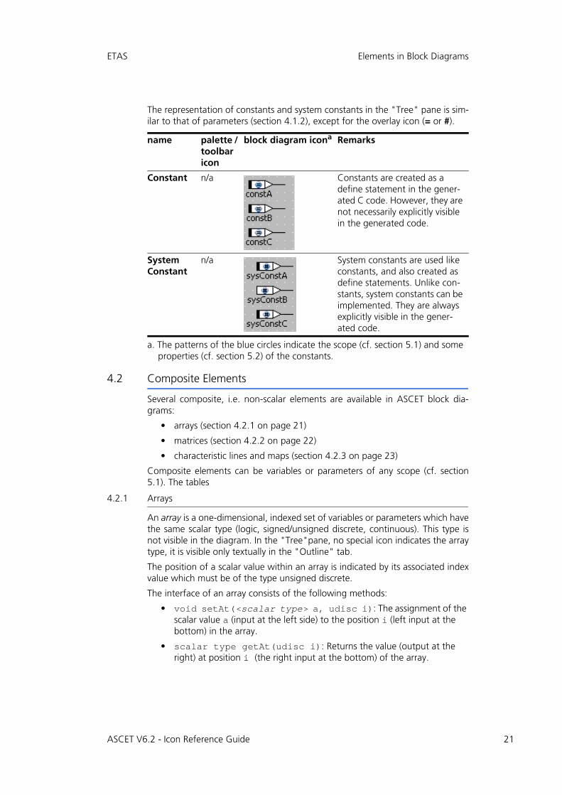
The representation of constants and system constants in the "Tree" pane is sim-ilar to that of parameters (section 4.1.2), except for the overlay icon (= or #).
4.2 Composite Elements
Several composite, i.e. non-scalar elements are available in ASCET block dia-grams:
• arrays (section 4.2.1 on page 21)
• matrices (section 4.2.2 on page 22)
• characteristic lines and maps (section 4.2.3 on page 23)
Composite elements can be variables or parameters of any scope (cf. section5.1). The tables
4.2.1 Arrays
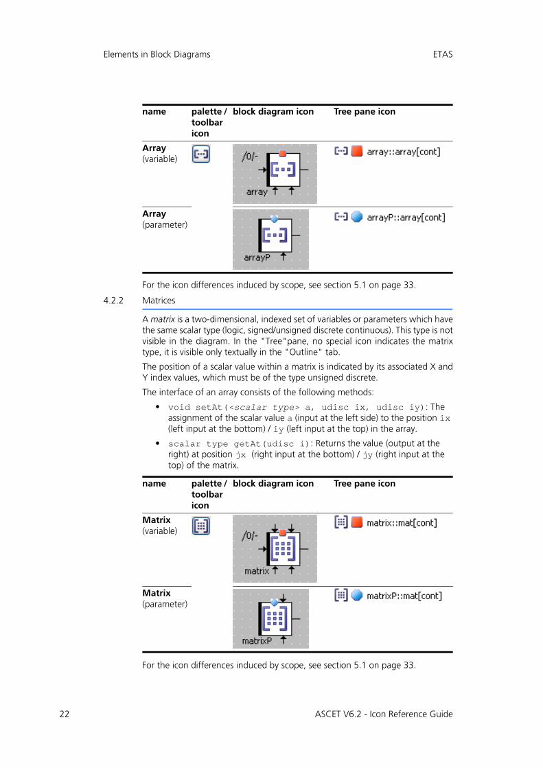
An array is a one-dimensional, indexed set of variables or parameters which havethe same scalar type (logic, signed/unsigned discrete, continuous). This type isnot visible in the diagram. In the "Tree"pane, no special icon indicates the arraytype, it is visible only textually in the "Outline" tab.
The position of a scalar value within an array is indicated by its associated indexvalue which must be of the type unsigned discrete.
The interface of an array consists of the following methods:
• void setAt(<scalar type> a, udisc i): The assignment of the scalar value a (input at the left side) to the position i (left input at the bottom) in the array.
• scalar type getAt(udisc i): Returns the value (output at the right) at position i (the right input at the bottom) of the array.
name palette / toolbar icon
block diagram icona
a. The patterns of the blue circles indicate the scope (cf. section 5.1) and some properties (cf. section 5.2) of the constants.
Remarks
Constant n/a Constants are created as a define statement in the gener-ated C code. However, they are not necessarily explicitly visible in the generated code.
System Constant
n/a System constants are used like constants, and also created as define statements. Unlike con-stants, system constants can be implemented. They are always explicitly visible in the gener-ated code.
ASCET V6.2 - Icon Reference Guide 21
22
Elements in Block Diagrams ETAS
For the icon differences induced by scope, see section 5.1 on page 33.
4.2.2 Matrices
A matrix is a two-dimensional, indexed set of variables or parameters which havethe same scalar type (logic, signed/unsigned discrete continuous). This type is notvisible in the diagram. In the "Tree"pane, no special icon indicates the matrixtype, it is visible only textually in the "Outline" tab.
The position of a scalar value within a matrix is indicated by its associated X andY index values, which must be of the type unsigned discrete.
The interface of an array consists of the following methods:
• void setAt(<scalar type> a, udisc ix, udisc iy): The assignment of the scalar value a (input at the left side) to the position ix (left input at the bottom) / iy (left input at the top) in the array.
• scalar type getAt(udisc i): Returns the value (output at the right) at position jx (right input at the bottom) / jy (right input at the top) of the matrix.
For the icon differences induced by scope, see section 5.1 on page 33.
name palette / toolbar icon
block diagram icon Tree pane icon
Array (variable)
Array (parameter)
name palette / toolbar icon
block diagram icon Tree pane icon
Matrix (variable)
Matrix (parameter)
ASCET V6.2 - Icon Reference Guide
ETAS Elements in Block Diagrams
4.2.3 Characteristic Lines and Maps
To support nonlinear control engineering, characteristic lines and maps are avail-able in ASCET block diagrams. They are used to describe a value in dependenceof one or two other values.
Characteristic lines and maps are available in the varieties normal, fixed, andgroup.
A fixed characteristic line/map has an equidistant distribution, i.e. the samplepoints have a constant distance from each other.
A group characteristic line/map does not contain a sample point distribution, butreferences an external distribution (cf. page 24) of sample points.
Characteristic Lines
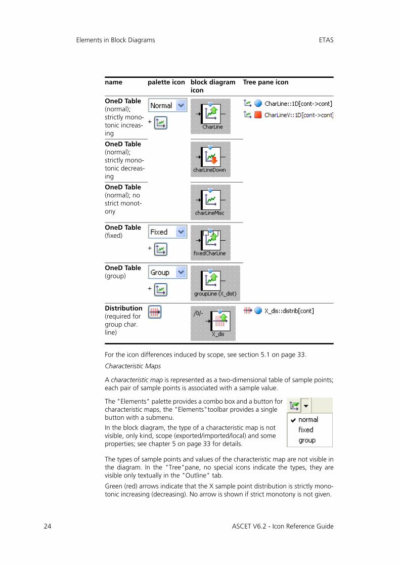
A characteristic line is represented as a one-dimensional table of sample points,each of which is associated with a sample value. The sample points represent theX axis of a function graph, the sample values represent the curve beingdescribed.
The types of sample points and values of the characteristic line are not visible inthe diagram. In the "Tree"pane, no special icons indicate the types, they arevisible only textually in the "Outline" tab.
Green (red) arrows indicate that the sample point distribution is strictly mono-tonic increasing (decreasing). No arrow is shown if strict monotony is not given.
The interface of a characteristic line consists of the following methods:
• void search (<arithmetic type> a): The supporting points surrounding a (input at the left) are searched, and the interpolation fac-tors are computed.
Available for normal/fixed characteristic lines and distributions of group characteristic lines.
• <arithmetic type> interpolate(): This method interpolates the value of the characteristic line from the interpolation factors and the value points at the associated supporting points. The result is returned (output on the right).
• <arithmetic type> getAt (<arithmetic type> a): is the combination of the search and interpolate method.
Not available for group characteristic lines.
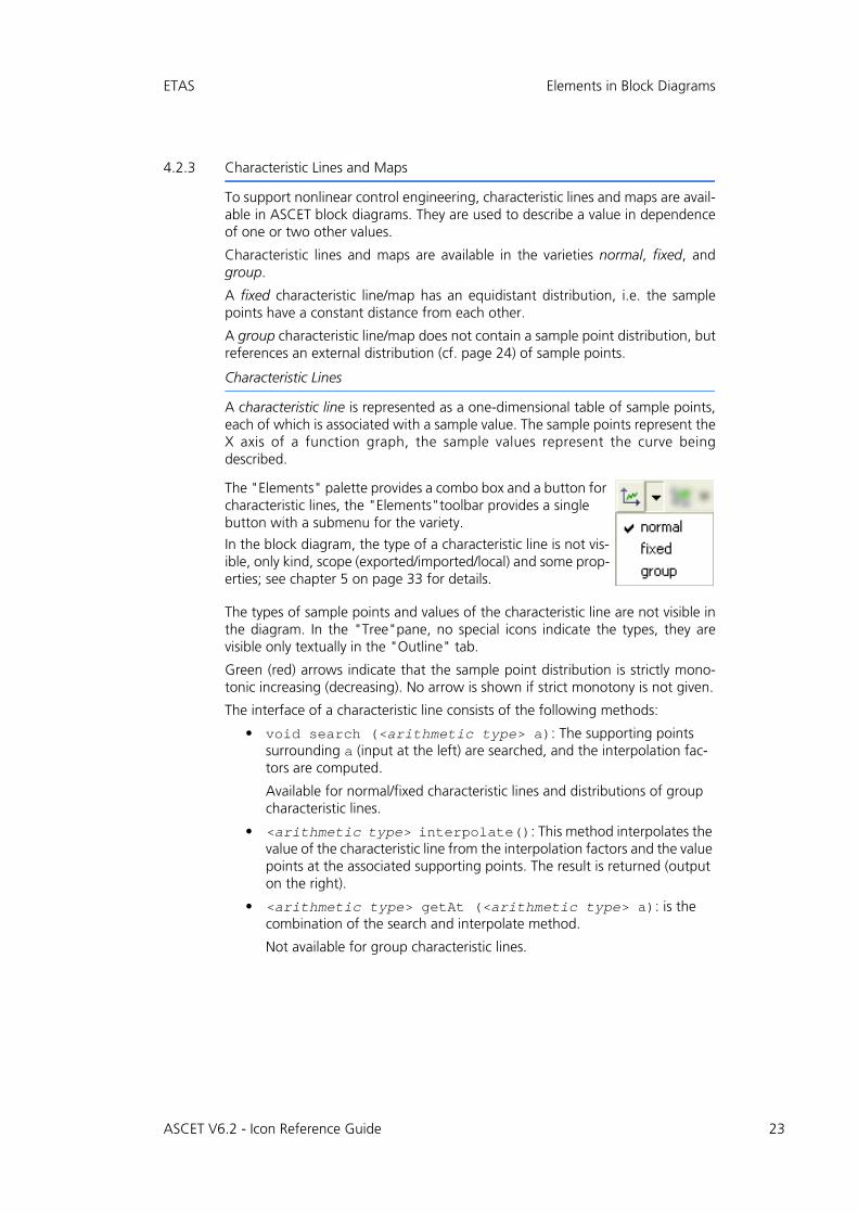
The "Elements" palette provides a combo box and a button for characteristic lines, the "Elements"toolbar provides a single button with a submenu for the variety.
In the block diagram, the type of a characteristic line is not vis-ible, only kind, scope (exported/imported/local) and some prop-erties; see chapter 5 on page 33 for details.
ASCET V6.2 - Icon Reference Guide 23
24
Elements in Block Diagrams ETAS
For the icon differences induced by scope, see section 5.1 on page 33.
Characteristic Maps
A characteristic map is represented as a two-dimensional table of sample points;each pair of sample points is associated with a sample value.
The types of sample points and values of the characteristic map are not visible inthe diagram. In the "Tree"pane, no special icons indicate the types, they arevisible only textually in the "Outline" tab.
Green (red) arrows indicate that the X sample point distribution is strictly mono-tonic increasing (decreasing). No arrow is shown if strict monotony is not given.
name palette icon block diagram icon
Tree pane icon
OneD Table (normal); strictly mono-tonic increas-ing
+
OneD Table (normal); strictly mono-tonic decreas-ing
OneD Table (normal); no strict monot-ony
OneD Table (fixed)
+
OneD Table (group)
+
Distribution (required for group char. line)
The "Elements" palette provides a combo box and a button for characteristic maps, the "Elements"toolbar provides a single button with a submenu.
In the block diagram, the type of a characteristic map is not visible, only kind, scope (exported/imported/local) and some properties; see chapter 5 on page 33 for details.
ASCET V6.2 - Icon Reference Guide
ETAS Elements in Block Diagrams
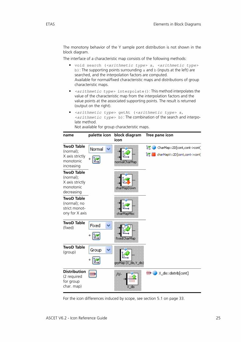
The monotony behavior of the Y sample pont distribution is not shown in theblock diagram.
The interface of a characteristic map consists of the following methods:
• void search (<arithmetic type> a, <arithmetic type> b): The supporting points surrounding a and b (inputs at the left) are searched, and the interpolation factors are computed.Available for normal/fixed characteristic maps and distributions of group characteristic maps.
• <arithmetic type> interpolate(): This method interpolates the value of the characteristic map from the interpolation factors and the value points at the associated supporting points. The result is returned (output on the right).
• <arithmetic type> getAt (<arithmetic type> a, <arithmetic type> b): The combination of the search and interpo-late method. Not available for group characteristic maps.
For the icon differences induced by scope, see section 5.1 on page 33.
name palette icon block diagram icon
Tree pane icon
TwoD Table (normal); X axis strictly monotonic increasing
+
TwoD Table (normal); X axis strictly monotonic decreasing
TwoD Table (normal); no strict monot-ony for X axis
TwoD Table (fixed)
+
TwoD Table (group)
+
Distribution (2 required for group char. map)
ASCET V6.2 - Icon Reference Guide 25
26
Elements in Block Diagrams ETAS
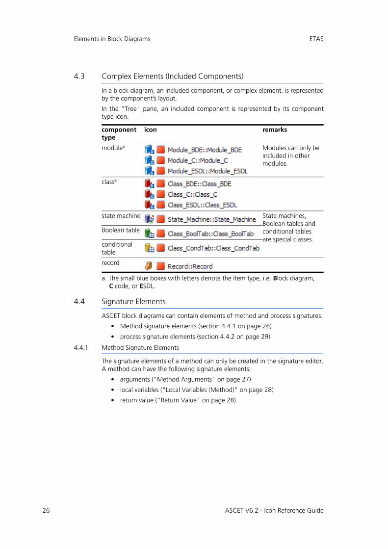
4.3 Complex Elements (Included Components)
In a block diagram, an included component, or complex element, is representedby the component’s layout.
In the "Tree" pane, an included component is represented by its componenttype icon.
4.4 Signature Elements
ASCET block diagrams can contain elements of method and process signatures.
• Method signature elements (section 4.4.1 on page 26)
• process signature elements (section 4.4.2 on page 29)
4.4.1 Method Signature Elements
The signature elements of a method can only be created in the signature editor.A method can have the following signature elements:
• arguments ("Method Arguments" on page 27)
• local variables ("Local Variables (Method)" on page 28)
• return value ("Return Value" on page 28)
component type
icon remarks
modulea
a. The small blue boxes with letters denote the item type, i.e. Block diagram, C code, or ESDL.
Modules can only be included in other modules.
classa
state machine State machines, Boolean tables and conditional tables are special classes.
Boolean table
conditional table
record
ASCET V6.2 - Icon Reference Guide
ETAS Elements in Block Diagrams
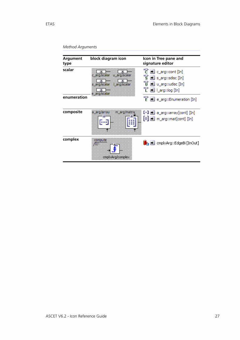
Method Arguments
Argument type
block diagram icon Icon in Tree pane and signature editor
scalar
enumeration
composite
complex
ASCET V6.2 - Icon Reference Guide 27
28
Elements in Block Diagrams ETAS
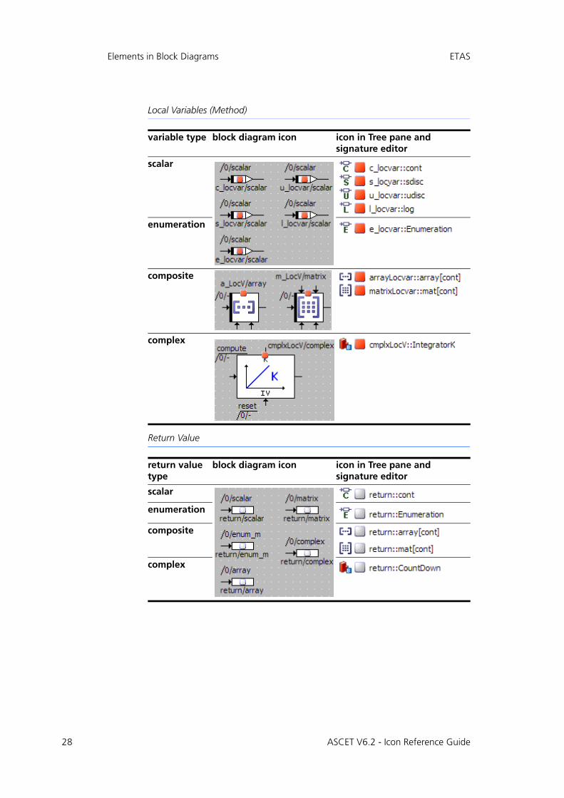
Local Variables (Method)
Return Value
variable type block diagram icon icon in Tree pane and signature editor
scalar
enumeration
composite
complex
return value type
block diagram icon icon in Tree pane and signature editor
scalar
enumeration
composite
complex
ASCET V6.2 - Icon Reference Guide
ETAS Elements in Block Diagrams
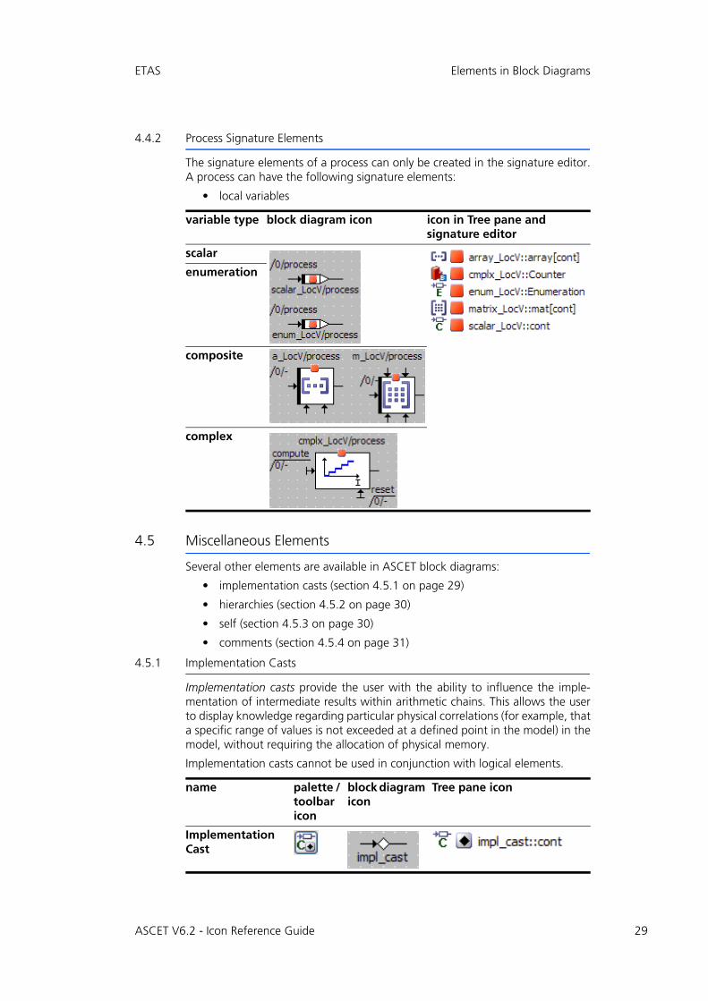
4.4.2 Process Signature Elements
The signature elements of a process can only be created in the signature editor.A process can have the following signature elements:
• local variables
4.5 Miscellaneous Elements
Several other elements are available in ASCET block diagrams:
• implementation casts (section 4.5.1 on page 29)
• hierarchies (section 4.5.2 on page 30)
• self (section 4.5.3 on page 30)
• comments (section 4.5.4 on page 31)
4.5.1 Implementation Casts
Implementation casts provide the user with the ability to influence the imple-mentation of intermediate results within arithmetic chains. This allows the userto display knowledge regarding particular physical correlations (for example, thata specific range of values is not exceeded at a defined point in the model) in themodel, without requiring the allocation of physical memory.
Implementation casts cannot be used in conjunction with logical elements.
variable type block diagram icon icon in Tree pane and signature editor
scalar
enumeration
composite
complex
name palette / toolbar icon
block diagram icon
Tree pane icon
Implementation Cast
ASCET V6.2 - Icon Reference Guide 29
30
Elements in Block Diagrams ETAS
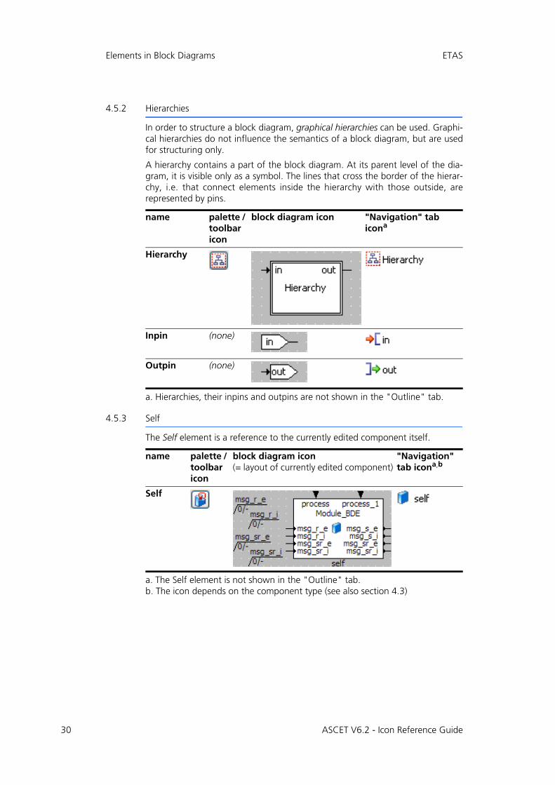
4.5.2 Hierarchies
In order to structure a block diagram, graphical hierarchies can be used. Graphi-cal hierarchies do not influence the semantics of a block diagram, but are usedfor structuring only.
A hierarchy contains a part of the block diagram. At its parent level of the dia-gram, it is visible only as a symbol. The lines that cross the border of the hierar-chy, i.e. that connect elements inside the hierarchy with those outside, arerepresented by pins.
4.5.3 Self
The Self element is a reference to the currently edited component itself.
name palette / toolbar icon
block diagram icon "Navigation" tab icona
a. Hierarchies, their inpins and outpins are not shown in the "Outline" tab.
Hierarchy
Inpin (none)
Outpin (none)
name palette / toolbar icon
block diagram icon(= layout of currently edited component)
"Navigation" tab icona,b
a. The Self element is not shown in the "Outline" tab.b. The icon depends on the component type (see also section 4.3)
Self
ASCET V6.2 - Icon Reference Guide
ETAS Elements in Block Diagrams
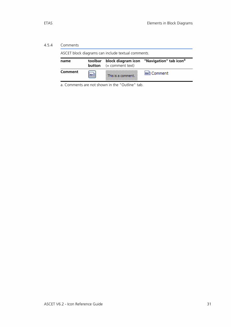
4.5.4 Comments
ASCET block diagrams can include textual comments.
name toolbar button
block diagram icon(= comment text)
"Navigation" tab icona
a. Comments are not shown in the "Outline" tab.
Comment
ASCET V6.2 - Icon Reference Guide 31
32
Elements in Block Diagrams ETAS
ASCET V6.2 - Icon Reference Guide
ETAS Miscellaneous Icons
5 Miscellaneous Icons
This chapter lists various icons used for different purposes in block diagrams.
• section 5.1 "Scope Icons" on page 33
• section 5.2 "Icons for Properties" on page 34
• section 5.3 "Icons in the "Tree" Pane" on page 35
• section 5.4 "Icons in the "General" Toolbar" on page 36
• section 5.5 "Icons in Tab Labels" on page 37
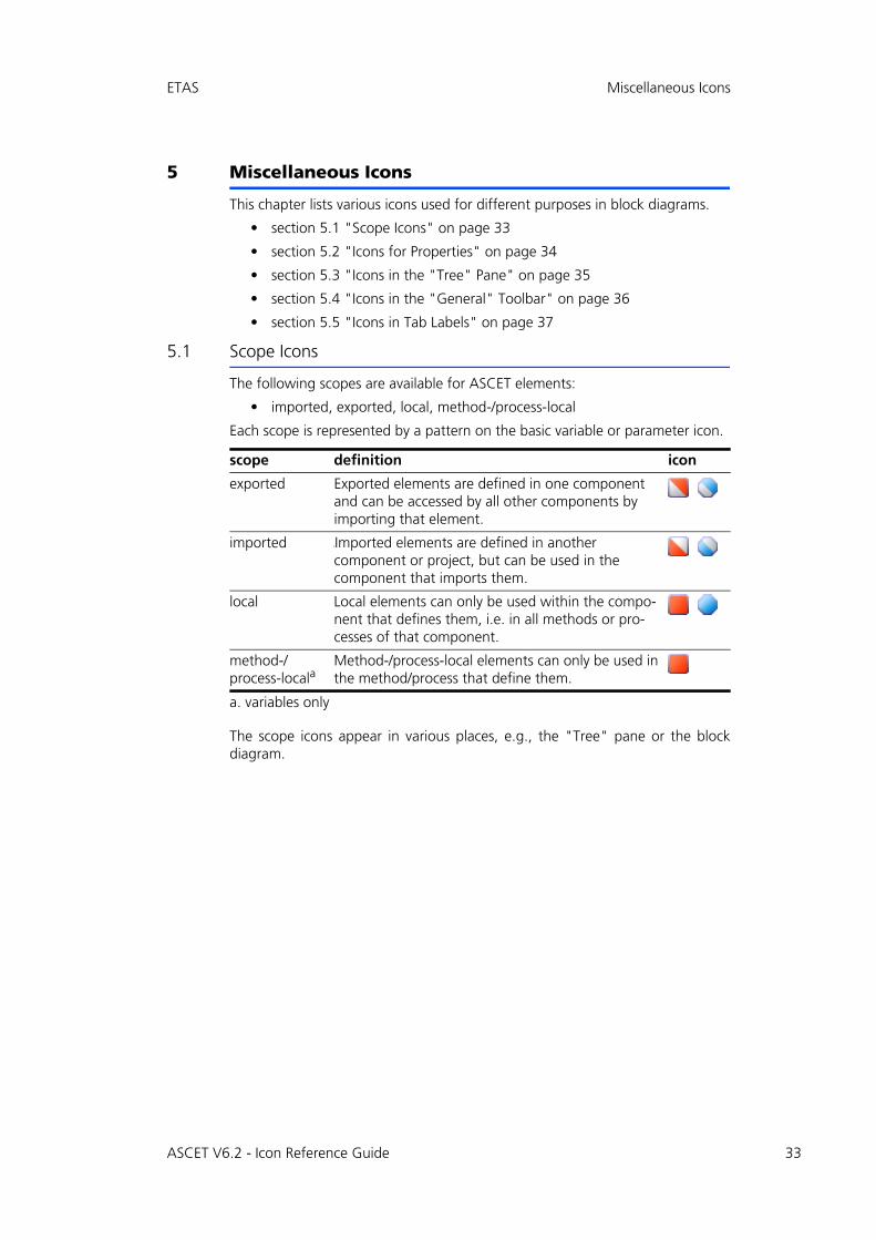
5.1 Scope Icons
The following scopes are available for ASCET elements:
• imported, exported, local, method-/process-local
Each scope is represented by a pattern on the basic variable or parameter icon.
The scope icons appear in various places, e.g., the "Tree" pane or the blockdiagram.
scope definition icon
exported Exported elements are defined in one component and can be accessed by all other components by importing that element.
imported IImported elements are defined in another component or project, but can be used in the component that imports them.
local Local elements can only be used within the compo-nent that defines them, i.e. in all methods or pro-cesses of that component.
method-/process-locala
a. variables only
Method-/process-local elements can only be used in the method/process that define them.
ASCET V6.2 - Icon Reference Guide 33
34
Miscellaneous Icons ETAS
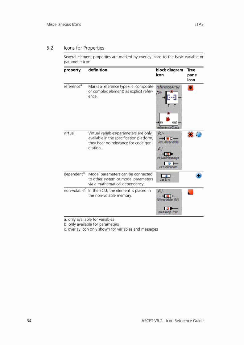
5.2 Icons for Properties
Several element properties are marked by overlay icons to the basic variable orparameter icon.
property definition block diagram icon
Tree pane Icon
referencea
a. only available for variables
Marks a reference type (i.e. composite or complex element) as explicit refer-ence.
virtual Virtual variables/parameters are only available in the specification platform, they bear no relevance for code gen-eration.
dependentb
b. only available for parameters
Model parameters can be connected to other system or model parameters via a mathematical dependency.
non-volatilec
c. overlay icon only shown for variables and messages
In the ECU, the element is placed in the non-volatile memory.
ASCET V6.2 - Icon Reference Guide
ETAS Miscellaneous Icons
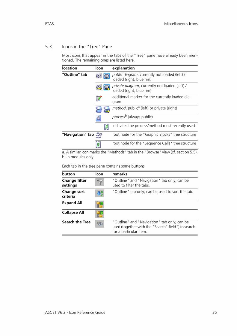
5.3 Icons in the "Tree" Pane
Most icons that appear in the tabs of the "Tree" pane have already been men-tioned. The remaining ones are listed here.
Each tab in the tree pane contains some buttons.
location icon explanation
"Outline" tab public diagram, currently not loaded (left) / loaded (right, blue rim)
private diagram, currently not loaded (left) / loaded (right, blue rim)
additional marker for the currently loaded dia-gram
method, publica (left) or private (right)
a. A similar icon marks the "Methods" tab in the "Browse" view (cf. section 5.5).
processb (always public)
b. in modules only
indicates the process/method most recently used
"Navigation" tab root node for the "Graphic Blocks" tree structure
root node for the "Sequence Calls" tree structure
button icon remarks
Change filter settings
"Outline" and "Navigation" tab only; can be used to filter the tabs.
Change sort criteria
"Outline" tab only; can be used to sort the tab.
Expand All
Collapse All
Search the Tree "Outline" and "Navigation" tab only; can be used (together with the "Search" field") to search for a particular item.
ASCET V6.2 - Icon Reference Guide 35
36
Miscellaneous Icons ETAS
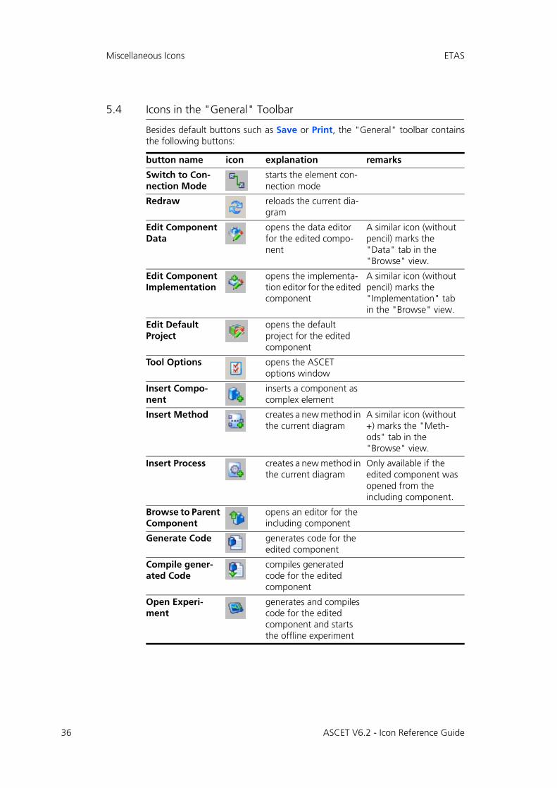
5.4 Icons in the "General" Toolbar
Besides default buttons such as Save or Print, the "General" toolbar containsthe following buttons:
button name icon explanation remarks
Switch to Con-nection Mode
starts the element con-nection mode
Redraw reloads the current dia-gram
Edit Component Data
opens the data editor for the edited compo-nent
A similar icon (without pencil) marks the "Data" tab in the "Browse" view.
Edit Component Implementation
opens the implementa-tion editor for the edited component
A similar icon (without pencil) marks the "Implementation" tab in the "Browse" view.
Edit Default Project
opens the default project for the edited component
Tool Options opens the ASCET options window
Insert Compo-nent
inserts a component as complex element
Insert Method creates a new method in the current diagram
A similar icon (without +) marks the "Meth-ods" tab in the "Browse" view.
Insert Process creates a new method in the current diagram
Only available if the edited component was opened from the including component.
Browse to Parent Component
opens an editor for the including component
Generate Code generates code for the edited component
Compile gener-ated Code
compiles generated code for the edited component
Open Experi-ment
generates and compiles code for the edited component and starts the offline experiment
ASCET V6.2 - Icon Reference Guide
ETAS Miscellaneous Icons
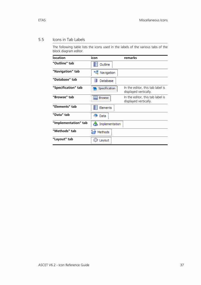
5.5 Icons in Tab Labels
The following table lists the icons used in the labels of the various tabs of theblock diagram editor.
location icon remarks
"Outline" tab
"Navigation" tab
"Database" tab
"Specification" tab In the editor, this tab label is displayed vertically.
"Browse" tab In the editor, this tab label is displayed vertically.
"Elements" tab
"Data" tab
"Implementation" tab
"Methods" tab
"Layout" tab
ASCET V6.2 - Icon Reference Guide 37
38
Miscellaneous Icons ETAS
ASCET V6.2 - Icon Reference Guide
ETAS ETAS Contact Addresses
6 ETAS Contact Addresses
ETAS HQ
ETAS GmbH
ETAS Subsidiaries and Technical Support
For details of your local sales office as well as your local technical support teamand product hotlines, take a look at the ETAS website:
Borsigstraße 14 Phone: +49 711 89661-0
70469 Stuttgart Fax: +49 711 89661-106
Germany WWW: www.etas.com
ETAS subsidiaries WWW: www.etas.com/en/contact.php
ETAS technical support WWW: www.etas.com/en/hotlines.php
ASCET V6.2 - Icon Reference Guide 39
40
ETAS Contact Addresses ETAS
ASCET V6.2 - Icon Reference Guide
ETAS Index
Index
AAbsolute 11Addition 7And 9Arithmetic Operators 7Array 21BBetween 10Break 15
CCase 10Case Operator 9characteristic line 23
fixed 24group 24
characteristic map 24fixed 25group 25
comment 31Comparison Operators 8complex element 26
composite elements 21–25array 21characteristic line 23characteristic map 24distribution 24, 25matrix 22oneD table 24twoD table 25
Constant 20Continuous Literal 0.0 20Continuous Literal 1.0 20Continuous Parameter 18Continuous Variable 17control flow elements 13–15
break 15if...then 13if...then...else 13switch 14while 14
DDistribution 24, 25Division 7dT 20dT Parameter 20
ASCET V6.2 - Icon Reference Guide 41
42
Index ETAS
Eelements 17–31
array 21characteristic line 23characteristic map 24comment 31complex ~ 26composite 21constants 20distribution 24, 25dT parameter 20hierarchy 30implementation cast 29included component 26literals 20matrix 22messages 18method argument 27method signature 26method-local variable 28miscellaneous 29oneD table 24parameters 18process signature 29real-time elements 18receive message 19resource 19return value 28scalar 17self 30send & receive message 19send message 19signature ~ 26system constants 20twoD table 25variables 17
Enumeration Literal 20Enumeration Parameter 18Enumeration Variable 17Equal 8ETAS Contact Addresses 39
GGeneral toolbar 36Greater 8Greater or Equal 8
Hhierarchy 30
IIf...Then 13
If...Then...Else 13implementation cast 29included component 26
LLiterals 20local variable
method 28process 29
Logic Literal false 20Logic Literal true 20Logic Parameter 18Logic Variable 17Logical Operators 9
MMatrix 22Max 10Messages 18, 20method argument 27method signature elements 26–28
argument 27local variable 28return value 28
Min 10miscellaneous 33–37
General toolbar 36properties 34scope 33tab label 37Tree pane 35
miscellaneous elements 29–31comment 31hierarchy 30implementation cast 29self 30
Miscellaneous Operators 10Modulo 7Multiplex Operator 9Multiplication 7Mux 9
NNavigation tab 35Negation 11Not 9Not Equal 8
OOneD Table 24
ASCET V6.2 - Icon Reference Guide
ETAS Index
operators 7–11absolute 11addition 7and 9between 10case 10division 7equal 8greater 8greater or equal 8max 10min 10modulo 7multiplication 7mux 9negation 11not 9not equal 8or 9smaller 8smaller or equal 8subtraction 7
Or 9Outline tab 35
PParameters 18process signature elements 29Product liability disclaimer 5properties icons 34
Rreal-time elements 18
dT parameter 20messages 18receive message 19resource 19send & receive message 19send message 19
Receive Message 19Resource 19return value 28
SSafety Instructions
technical state 5
scalar elements 17–21constants 20continuous literal 0.0 20continuous literal 1.0 20continuous parameter 18continuous variable 17dT parameter 20enumeration literal 20enumeration parameter 18enumeration variable 17literals 20logic literal false 20logic literal true 20logic parameter 18logic variable 17messages 18parameters 18real-time elements 18receive message 19send & receive message 19send message 19signed discrete parameter 18signed discrete variable 17system constants 20unsigned discrete parameter 18unsigned discrete variable 17variables 17
scope icon 33self 30Send & Receive Message 19Send Message 19signature elements 26–29
method argument 27method-local variable 28process-local variable 29return value 28
Signed Discrete Parameter 18Signed Discrete Variable 17Smaller 8Smaller or Equal 8Subtraction 7Switch 14System Constant 20
Ttab label 37Tree pane 35
buttons 35TwoD Table 25
UUnsigned Discrete Parameter 18
ASCET V6.2 - Icon Reference Guide 43
44
Index ETAS
Unsigned Discrete Variable 17
VVariables 17
WWhile 14
ASCET V6.2 - Icon Reference Guide


![Netex learningApp | What's New v6.2 [EN]](https://static.fdocuments.us/doc/165x107/5879b4841a28ab6b2c8b651f/netex-learningapp-whats-new-v62-en.jpg)
