AS GOOD AS IT CAN BE VENTILATION SYSTEM...
11
AS GOOD AS IT CAN BE VENTILATION SYSTEM DESIGN BY A COMBINED SCALING AND DISCRETE OPTIMIZATION METHOD Christian SCHÄNZLE 1 , Lena C. ALTHERR 1 , Thorsten EDERER 1 , Ulf LORENZ 2 , Peter F. PELZ 1 1 Technische Universität Darmstadt, Chair of Fluid Systems, Magdalenenstr. 4, 64289 Darmstadt, Germany 2 Universität Siegen, Chair for Technology Management, Hölderlinstr. 3, 57076 Siegen, Germany SUMMARY The understanding that optimized components do not automatically lead to energy-efficient systems sets the attention from the single component on the entire technical system. At TU Darmstadt, a new field of research named Technical Operations Research (TOR) has its origin. It combines mathematical and technical know-how for the optimal design of technical systems. We illustrate our optimization approach in a case study for the design of a ventilation system with the ambition to minimize the energy consumption for a temporal distribution of diverse load demands. By combining scaling laws with our optimization methods we find the optimal combination of fans and show the advantage of the use of multiple fans. INTRODUCTION Designing complex ventilation systems is a challenging task. The required operation can be fulfilled with numerous different combinations of fans, and the application engineer has to choose an adequate set-up. Thereby the focus lies primarily on the functional quality of the system, whereas the future energy consumption often plays a subordinate role in the design process. Often, only one fan is chosen that fulfills the peak operation load and that is driven in its best operating point in this ‘worst case’ loading condition [1]. When it comes to a temporal distribution of different loading conditions, multiple smaller fans may be more efficient. Thus, the designer does not only have to construct a system for a single operating point, but hast to consider multiple demands at the same time. This leads to discrete decisions, like: Shall I buy fan 1 or fan 2? Are two
Transcript of AS GOOD AS IT CAN BE VENTILATION SYSTEM...

AS GOOD AS IT CAN BE
VENTILATION SYSTEM DESIGN BY A COMBINED
SCALING AND DISCRETE OPTIMIZATION METHOD
Christian SCHÄNZLE1, Lena C. ALTHERR1, Thorsten EDERER1, Ulf LORENZ2, Peter F. PELZ1
1 Technische Universität Darmstadt,
Chair of Fluid Systems, Magdalenenstr. 4,
64289 Darmstadt, Germany
2 Universität Siegen,
Chair for Technology Management, Hölderlinstr. 3,
57076 Siegen, Germany
SUMMARY
The understanding that optimized components do not automatically lead to energy-efficient systems sets the attention from the single component on the entire technical system. At TU Darmstadt, a new field of research named Technical Operations Research (TOR) has its origin. It combines mathematical and technical know-how for the optimal design of technical systems. We illustrate our optimization approach in a case study for the design of a ventilation system with the ambition to minimize the energy consumption for a temporal distribution of diverse load demands. By combining scaling laws with our optimization methods we find the optimal combination of fans and show the advantage of the use of multiple fans.
INTRODUCTION
Designing complex ventilation systems is a challenging task. The required operation can be fulfilled with numerous different combinations of fans, and the application engineer has to choose an adequate set-up. Thereby the focus lies primarily on the functional quality of the system, whereas the future energy consumption often plays a subordinate role in the design process.
Often, only one fan is chosen that fulfills the peak operation load and that is driven in its best operating point in this ‘worst case’ loading condition [1]. When it comes to a temporal distribution of different loading conditions, multiple smaller fans may be more efficient. Thus, the designer does not only have to construct a system for a single operating point, but hast to consider multiple demands at the same time. This leads to discrete decisions, like: Shall I buy fan 1 or fan 2? Are two

FAN 2015 2 Lyon (France), 15 – 17 April 2015
fans better than one? Each decision affects the energy consumption of the system. However, due to the multitude of different fan combinations and operating strategies, even for an experienced engineer it is not possible to keep track of all possibilities.
In this paper we use the methods of the new research direction with its origin at TU Darmstadt called Technical Operations Research (TOR) for the design of energetically optimal technical systems. Our approach is based on the insight that optimized components do not automatically lead to energy-efficient systems. Instead of optimizing the energy efficiency of single components, we focus on the whole technical system. With TOR, we design the most energy-efficient ventilation system out of a given kit of fans and derive the optimal control settings for loading conditions with different distribution probabilities.
Technical Application: A Ventilation System
We illustrate our optimization approach by designing an energetically optimal ventilation system for an office floor with two bureaus and a conference room. For these rooms, a time-dependent occupation density�(�), sketched in Fig. 1, is given. In the applied example the task of the ventilation system is to convey the heat produced by people, light and computers in order to keep the temperature in the room on a constant level. The axiomatic approach for one room, i.e., the first law of thermodynamics reads
���dd� + �� ℎ� = �� . (1)
The first term on the left hand side is the local change of internal energy, where � is the mass of air in the room, �� the isochoric specific heat capacity and d/d� the derivative of the room temperature. The second term is the convective change of energy, where �� is the mass flow rate and ℎ� the total enthalpy difference. �� is the heat source, i.e., the heat produced in one room. In the quasi-static approximation the first term is small in comparison to �� and is neglected. The heat conduction through walls is also neglected. All quantities are determined as time-weighted average values. If we assume ideal mixing in the rooms and consider air as an ideal caloric gas, we can derive a simple relation between the volume flow rate �� ,and the produced heat �� (�) as a function of the occupation density �, and the temperature difference Δ�between the supplied air and the air in the room:
�� = �� (�)
����, �� (�) = ����������, + ��!�� "�, #
$
%&. (2)
Following VDI 2078 [2] we expect one person to be a heat source of ��������, = 120W and a
technical device to be heat source of ��!�� "�, = 30W. To achieve a comfortable cooling system,
?
?
?
OFFICE OFFICE CONFERENCE ROOMVENTILATION SYSTEM
�� �� ��
8 12 16 20 TIME
�
5
15
25
8 12 16 20 TIME
�
5
15
25
8 12 16 20 TIME
�
5
15
25
Figure 1: Ventilation system to be planned. Three office rooms with varying occupation density are to be ventilated.

FAN 2015 3 Lyon (France), 15 – 17 April 2015
Ihle et al. [3] recommend a temperature difference of Δ� = 2K between the temperature of the supplied air and the room temperature. Therefore we assume a constant temperature of the supplied air. Based on the occupation density, the required volume flows for our future ventilation system are given by Eq. 2. We are able to categorize the load profile into three major volume flow demands. Furthermore we assume the ventilation ducts to be fixed, i.e., the system characteristic is given as an input to the optimization model. As the conference room only has to be ventilated part-time, the system characteristic differs for the load demands which leads to the three quasi-steady-state load scenarios shown in Fig. 2. These scenarios have to be fulfilled by one set-up of fans. The task of our optimization algorithm is to find the energy optimal combination of fans and their control settings for each loading condition.
75 %
50 %
25 %
Δ-�. = 175Pa��. = 9300m5/h
Δ-�7 =150Pa��7 = 6200m5/h
Δ-�5 = 200Pa��5 = 12400m5/hT
IME P
ORTIO
N
Figure 2: Load profile consisting of three different load scenarios
TOR METHODOLOGY
If you ask three engineers to plan a ventilation system, the resulting systems will most probably differ in their network topology, control strategy, and most important, in their energy consumption and investment costs. This shows that at least two of these systems cannot be optimal. Moreover, with this experience-based approach alone, it is not possible to absolutely quantify the solution quality: no one can ever know if another engineer could find an even better design or not.
Our goal is to establish quantitative methods for the optimal synthesis of technical systems. We use mathematical optimization techniques, which are well known in economics under the name of Operations Research (OR), and apply them to system design in engineering. The one key factor that makes this approach superior is the objective quality criterion. In contrast to conventional heuristics like genetic algorithms, the optimization techniques we apply enable us to assess solution proposals and find the global optimal one. We can prove that our system design is as good as it can be. This feature is desired for an objective judgement of techno-economical scenarios.
To support engineers in applying this new methodology, we provide a straight-forward guideline. The systematical design approach is visualized by the TOR pyramid, shown in Fig. 3. It divides the planning process of a system into two phases: decision-making and execution. These two major phases are further subdivided into several steps. The width of each level symbolizes the accumulated complexity of the system. The first step (What is the function of the system?) and the last three steps (Verify!, Validate! and Lay Out!) represent the traditional experience-based approach. The steps in between encompass the relevant decisions for the energy-efficiency of the resulting system. However, these steps in particular are often carelessly neglected.
Following the TOR pyramid we can find the most energy efficient ventilation system as follows:
Step 1: What is the function? In this first step, the required operation of the yet to be planned system is specified. In this example, three different office rooms are to be ventilated. The time-dependent occupation density of the rooms leads to three different flow rate demands (cf. Fig. 2). The ducts are

FAN 2015 4 Lyon (France), 15 – 17 April 2015
fixed, i.e., the system characteristic and thus the required pressure rise is given as an input to the optimization model. Instead of only considering one reference demand, we cover three major diverse loads.
Step 2: What is my goal? We need to define the goal of the optimization by specifying an objective function. That is, we need to specify the features we look for in the system to be. Do we wish for a small maximum power consumption? Or do we want the system to be reasonably priced? In this paper, we look for the most energy-efficient system, i.e., we minimize the energy consumption of the ventilation system.
Step 3: How large is the playing field? This step is fundamentally novel to the system design task. Since the optimal system is identified by an algorithm, we need to shape the entirety of all possible (good and bad) designs to choose from. Many degrees of freedom can lead to a highly customized system that is ideal for the given load profile but may be sensitive to small variations. Vice versa, few degrees of freedom may result in a one-size-fits-all system which is not very efficient. For the design task at hand, we specify a kit of potential components out of which the optimizer may build the ventilation system. The kit contains axial fans which are described by their characteristic curves. Furthermore it must be clear that TOR will only find technical solutions that are part of the playing field and therefore will not replace human imagination or find creative solutions beyond the possible solutions.
Research „TOR“
5. VERIFY!
? 1. WHAT IS THE FUNCTION?
2. WHAT IS MY GOAL?
3. HOW LARGE IS THE PLAYING FIELD
4. FIND THE OPTIMAL SYSTEM!
DECISION-MAKING
EXECUTION
6. VALIDATE!
7. LAY OUT!
Figure 3: The TOR pyramid - a step by step guide towards an optimal system
Step 4: Find the optimal system! Now that we have concluded the Decision-Making phase, we can unlock the potential of TOR. We start by modelling all potential layouts of the system by a Mixed Integer Program (MIP). Out of the entirety of possible systems, the algorithm finds the global optimal one, i.e., it finds the most energy-efficient ventilation system in our exemplary design task. A naïve implementation could accomplish this by constructing all possible designs and by doing numerous parameter optimizations to assess the energy-efficiency of each design proposal. As opposed to this, our mathematical approach achieves an enormous speed-up by an intelligent traversal through the solution space and by tightening its assessment of the remaining optimization potential. Despite numerous system design and control options, this allows us to simultaneously find the system and the most energy-saving control settings that yield the best energy-efficiency.
Step 5: Verify! Having found the optimal solution with the help of TOR, the verification of our results is for us without question. For this, we use 0D-models and simulation environments like Modelica.
FAN 2015 5 Lyon (France), 15 – 17 April 2015
Step 6: Validate! In the process of designing a new system, validation is always a key element. It is conducted by comparison with experimental data or with simulations generated by three-dimensional computational methods.
Step 7: Lay Out! Once our optimal solution passes the validation tests, it is the turn of an experienced engineer to realize the system design proposed by our algorithm.
AFFINITY AND SCALING LAWS
Following the TOR methodology the optimization highly depends on the playing field, i.e., on the type, size and amount of available fans. Consequently, the decision that is made in step 3 has a big influence on the potential energy savings of the ventilation system to be planned.
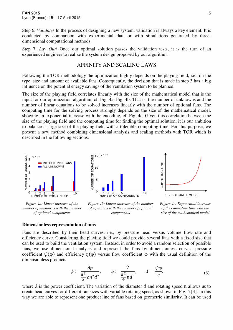
The size of the playing field correlates linearly with the size of the mathematical model that is the input for our optimization algorithm, cf. Fig. 4a, Fig. 4b. That is, the number of unknowns and the number of linear equations to be solved increases linearly with the number of optional fans. The computing time for the solving process strongly depends on the size of the mathematical model, showing an exponential increase with the encoding, cf. Fig. 4c. Given this correlation between the size of the playing field and the computing time for finding the optimal solution, it is our ambition to balance a large size of the playing field with a tolerable computing time. For this purpose, we present a new method combining dimensional analysis and scaling methods with TOR which is described in the following sections.
1 2 3 5 100
1
2
3
4
5x 10⁴
NUMBER OF COMPONENTS
NU
MBER O
F U
NKN
OW
NS
INTEGER UNKNOWNS
ALL UNKNOWNS
1 2 3 5 100
5
10
15 x 104
NU
MBER O
F E
QU
ATIO
NS
NUMBER OF COMPONENTS
CO
MPU
TIN
G T
IME
SIZE OF MATH. MODEL
Figure 4a: Linear increase of the
number of unknowns with the number
of optional components
Figure 4b: Linear increase of the number
of equations with the number of optional
components
Figure 4c: Exponential increase
of the computing time with the
size of the mathematical model
Dimensionless representation of fans
Fans are described by their head curves, i.e., by pressure head versus volume flow rate and efficiency curve. Considering the playing field we could provide several fans with a fixed size that can be used to build the ventilation system. Instead, in order to avoid a random selection of possible fans, we use dimensional analysis and represent the fans by dimensionless curves: pressure coefficient :(φ) and efficiency <(φ) versus flow coefficient φ with the usual definition of the dimensionless products
: ∶= ->.2 �?.@.
, φ ∶= ��>.4 ?@5
, A ∶= :φ< , (3)
where A is the power coefficient. The variation of the diameter @ and rotating speed ? allows us to create head curves for different fan sizes with variable rotating speed, as shown in Fig. 5 [4]. In this way we are able to represent one product line of fans based on geometric similarity. It can be used

FAN 2015 6 Lyon (France), 15 – 17 April 2015
by the optimization algorithm to find the optimal combination of fans for the given loading demands.
Δ-� d��
Δ-� ?:
B
AFFINITY LAWS
�� Figure 5: From dimensionless head curves to a product line
Efficiency scaling
When comparing two machines of the same shape but of different Reynolds number and Mach number, there will be a difference in efficiency at the best efficiency point (cf. Fig. 6). Hence, scaling laws serve to predict the change of efficiency< and pressure rise Δ-��� with the change of one or more of the following physical parameters:
o machine size, given by the impeller diameter @, o rotational speed Ω = 2>?, o kinematic viscosity D, o density �, o compressibility measured by the speed of sound E, o typical roughness height F, o gap width (centrifugal fans: gap between shroud and inlet) or tip clearance G (axial fans).
By means of dimensional analysis Pelz et. al. [5] derive a simple formula for the relation between these physical quantities
<, : = <, :(�H-I, JKLI, MNEOK�H), (4)
where type is determined by the specific speed � = ?�/157.8, size is determined by the Reynolds number QI and quality is determined by the machine shape, the surface roughness and – in the case of axial machines – the tip clearance.
Figure 6: Efficiency vs. specific speed � for different
Reynolds numbers developed at Chair of Fluid Systems [6]
Figure 7: Product line of axial fans, i.e. specific
speed σ=const., for increasing Reynolds number

FAN 2015 7 Lyon (France), 15 – 17 April 2015
We want to derive a scaling law for the calculation of the characteristics of our product line, which contains fans of the same type, i.e. constant specific speed σ, but of different scales (cf. Fig. 7). We aim to predict the change in efficiency with altered rotational speed for the same machine, as well. Thus, scaling laws need to be reliable not only at the best point, but also at off peak condition while being of course easy to apply.
For this purpose, Pelz et. al. [5] present a scale up formula that is based on the total derivative of the inefficiency S = 1 − <. The definition for inefficiency reads
S ≔ VWV, (5)
where VW denotes power losses due to dissipation. The total differential of Eq. 5 gives (see Spurk [7])
−d< = (1 − <) dVWVW
− (1 − <). dVVW
≈ (1 − <) dVWVW
= (1 − <) d�Y�Y
, (6)
where the second term in Eq.6 is much smaller compared to the other terms and can be neglected. With the definition of the inefficiency S Eq. 6 can also be read
dSS = d�Y
�Y, (7)
i. e., the logarithmic change of inefficiency and friction factor are equal. Following Blasius law [8] for a plate and hydraulically smooth flow the friction coefficient is
�Z = 0.074QI[7/\. (8)
This definition of the friction coefficient with Eq. 7 yields to
dSS = −1
5dQIQI . (9)
Finally the scale up formula
Δ< = 15 (1 − <]) ΔQI
QI^ (10)
is given which we use to calculate the characteristics of our product line that represents our playing field.
Applying affinity and scaling laws in combination with TOR is a reliable way to complement our optimization task of finding the energetically optimal combination of fans.
MATHEMATICAL PROGRAM
The optimization task of finding the most energy-efficient ventilation system can be expressed as a mixed-integer linear program (MILP). This formulation – consisting of discrete and continuous unknowns with linear constraints – allows for efficient solution techniques. The same algorithms have been successfully applied to huge Operations Research problems, e.g., multinational logistics [9].
We model the interconnection of the given optional fans by a network graph _(�, `). Its edges ` represent the possible fans and pipes, while its vertices � correspond to connection points between these components. While passing edges – that stand for fans or pipes – changes the pressure, the connection points can be compared to imaginary measuring points, where a certain pressure can be measured.

FAN 2015 8 Lyon (France), 15 – 17 April 2015
For the given technical application, we consider only parallel connections of fans, but our methodology would also allow for more topological degrees of freedom, i.e., for general series-parallel networks.
The purchase decision, i.e., how many fans shall be bought for the optimal system, is indicated by a binary decision variable a ,b for each optional fan (K, c)d`. For a ,b = 1, the fan is bought, for a ,b = 0 not. In addition to the purchase indicator, we introduce a binary activation indicator E ,b,�" for each optional fan (K, c) and for each of the given loading scenarios J�dG�. This allows to activate (E ,b,�" = 1) or deactivate (E ,b,�" = 0) a purchased fan while fulfilling a certain demand in one of the given loading scenarios. Since a fan can only be activated if it has been bought, we include the inequation
∀J�dG�:E ,b,�" ≤ a ,b (11)
in our model formulation.
The vertices and edges of the network graph also carry information about the physical quantities and technical properties of the ventilation system. For the given load cases we assume a stationary flow. That is, we can reduce the temporal and spatial resolution and consider only relevant balance equations.
One of these balance equations is the conservation of the mass flow. It is modeled in the MILP by the following equation: In each loading scenario J�dG� the sum of the volume flows on all edges going into a vertex hd� and the sum of the volume flows on all edges going out of a vertex hd� are equal
∀J�dG�, ∀hd�: � �� ,�,�"( ,�)∈j
= � ���,b,�"(�,b)∈j
. (12)
The purchase and activation decisions also have to be incorporated into the model constraints, because technical properties are altered and physical requirements may become obsolete. For instance an additional condition with an adequate upper limit ��̂ klmakes sure that only active fans contribute to the volume flow conservation:
�� ,b,�" ≤��̂ klE ,b. (13)
In each scenario J�dG�,the pressure propagation has to be fulfilled along each edge (K, c), if the fan corresponding to this edge is active in this scenario. This is made sure by a combination of two linear inequations:
-b,�" ≤- ,�" + ∆- ,b,�" + -^klE ,b, (14)
-b,�" ≥- ,�" + ∆- ,b,�" − -^klE ,b, (15)
where the pressure increase ∆- ,b,�" of a fan (K, c) conducting the volume flow �� ,b,�"is given by its head curve.
Instead of only including head curves of individual fans into our model formulation, we represent a superset of potential fans by dimensionless head curves. We allow for two kinds of continuous changes: On the one hand, we integrate scaling laws into the model. That is, the technical properties of the fan adapt to changes in the fan geometry, i.e., the fan diameter. This decision must be taken at the time of purchase. On the other hand, the rotary speed of each fan can be controlled during operation to respond to changes in the load.

FAN 2015 9 Lyon (France), 15 – 17 April 2015
The dimensionless fan characteristics and the affinity and scaling laws are integrated into the MILP by piecewise linearization. Due to its good performance in benchmarks we chose a 2D logarithmical method [10] to represent the following relations:
Δ- = >.
2 :�?.@., �� = >.
4 B?@5, Vo = >p
8 A�?5@\. (16)
OPTIMIZATION RESULTS
For the optimization of the ventilation system a case study has been conducted that includes binary decisions for two optimization parameters, as shown in Fig. 8. We vary the optimization parameters as follows:
1. Definition of the function to be fulfilled by the future system: In our case study, the function of the system is defined in two different ways. Firstly, by a single maximum load demand and secondly by a more fine grained load scenario (cf. Fig. 2). Nonetheless in both cases we judge the optimal solutions based on the energy consumption of the given load scenario. By varying these initial conditions, i.e., the input loads of our optimization, we investigate their influence on the energy consumption.
2. Number of possible fans: For one part of our optimizations, we only allow the use of one fan, and compare these results to calculations where multiple fans are possible. This means that we are able to examine the influence of topology variation on the optimization results, i.e., if we can reduce the energy consumption of the system.
MAX. LOAD DEMAND THREE SCENARIOS
LOAD SCENARIOS
NUMBER OF FANS
OPTIMIZATION RESULT
Figure 8: Variation of three optimization parameters
The diameter of the fans is another degree of freedom that is chosen by the optimization algorithm. The limits for the diameter variation are set from 0.2m to 1m and can be varied continuously. The rotary speed of the fan can also be chosen continuously, in a range from 200 rpm to 2000 rpm.
In total we perform 4 optimizations under different conditions (see Table 1: optimization 1 to 4). Table 1 shows the 4 parameter variations and the corresponding optimization results, i.e., the number of chosen fans and the energy consumption of the suggested systems. Table 2 shows the chosen fan sizes and control settings for the optimizations that have been carried out. As can be seen, the best solution considering only the maximum loading demand always is to choose one fan (optimization 1 and 2). The permission to use two fans has no influence on the design of the ventilation system if only one load demand is taken into account. Considering the load scenario as initial condition (optimization 3) a smaller fan is selected and the energy consumption can be reduced from 5.30kWh/day to 4.98kWh/day, which corresponds to a reduction of 6%. As soon as the use of two fans is allowed (optimization 4) a combination of two smaller fans is selected, that

FAN 2015 10 Lyon (France), 15 – 17 April 2015
are connected in parallel. With two fans, the energy consumption can be reduced to 4.80kWh/day, corresponding to an energy reduction of 9.4% compared to 5.30 kWh/day when only considering the maximum loading demand. The optimal operating strategy is to use the smaller fan for the first loading demand and the bigger fan for the two other demands.
Table 1: Optimization results for the case study
OPTIMIZATION INITIAL
CONDITION
NUMBER OF
POSSIBLE FANS
NUMBER OF
CHOSEN FANS
ENERGY
CONSUMPTION
in tuvwxy
1 max load one one 5.30
2 max load two one 5.30
3 scenario one one 4.98
4 scenario two two 4.80
Table 2: Optimization Results – Selected fan size and control settings
OPTIMIZATION NUMBER OF
POSSIBLE FANS
DIAMETER
OF FAN
in z
ROTARY SPEED
FOR SCENARIO 1,2,3
(cf. Fig. 2) in rpm
1 one 0.69 ?7 = 828;?. = 948;?5 = 1080
2 two 0.69 ?7 = 828;?. = 948;?5 = 1080
3 one 0.55 ?7 = 1134;?. = 1413;?5 = 1704
4 two @7 = 0.61 ?7 = 0;?. = 1143;?5 = 1349
@. = 0.51 ?7 = 1259;?. = 0;?5 = 0
CONCLUSION
We introduced a new optimization method named Technical Operations Research (TOR) and illustrated our optimization approach in a case study for the optimal design of a ventilation system. By applying affinity and scaling laws in combination with TOR we are able to find the optimal combination of fans for a diverse load scenario. The optimization results show that the consideration of a load scenario instead of a single load demand improves the optimal solution: The use of multiple fans is beneficial in terms of energy consumption.
In future research projects we plan to experimentally validate our optimization solutions for ventilation systems. Moreover, the existing mathematical model can be extended to conduct further optimizations, such as finding the optimal ventilation system given more diverse load scenarios for larger buildings or considering heating and cooling devices in the ventilation system. In particular, if one fan alone is not able to supply the required maximum load demand, discrete decisions will have a stronger impact on the optimal solution and the whole potential of TOR is used.
ACKNOWLEDGEMENTS
This work is partially supported by the German Federal Ministry for Economic Affairs and Energy funded project “Entwicklung hocheffizienter Pumpensysteme” and by the German Research Foundation (DFG) funded Collaborative Research Centre SFB 805.

FAN 2015 11 Lyon (France), 15 – 17 April 2015
BIBLIOGRAPHY
[1] P.G. Schild, M. Mysen – Recommendations on Specific Fan Power and Fan System Efficiency, Technical Note AIVC 65, 2009
[2] Verein Deutscher Ingenieure (VDI) – Berechnung der Kühllast klimatisierter Räume (VDI-
Kühllastregeln), VDI 2078, Beuth Verlag GmbH, Berlin, 2007
[3] C. Ihle, R. Bader, M. Golla – Tabellenbuch Sanitär, Heizung, Lüftung, 2. Auflage, Verlag Dr. Max Gehlen, 1998
[4] T. Carolus – Ventilatoren, 3. Auflage, Springer Vieweg, 2012
[5] P.Pelz, S. Stonjek, B. Matyschok – The influence of Reynolds number and roughness on the
efficiency of axial and centrifugal fans – A physically based scaling method, Proceedings of FAN, lsevier Science Ltd, Senlis, 2012
[6] European Association of Pump Manufacturers – Attainable efficiencies of volute casing pumps:
a reference guide, Elsevier Science Ltd, Kidlington, 1999
[7] J. H. Spurk – Dimensionsanalyse in der Strömungslehre, Springer-Verlag, Berlin, 1992
[8] H. Schlichting – Boundary Layer Theory, New York: McGraw-Hill, 1979
[9] T. Schöneberg, A. Koberstein, L. Suhl – An optimization model for automated selection of
economic and ecologic delivery profiles in area forwarding based inbound logistics networks,
Flexible Services and Manufacturing Journal, Springer, 2010
[10] J. P. Vielma, S. Ahmed, G. Nemhauser – Mixed-Integer Models for Nonseparable Piecewise-
Linear Optimization: Unifying Framework and Extensions, Operations Research 58(2), INFORMS, 2010