arnd SV'erification - ntrs.nasa.gov · 22215-ho 4-ro-00 space shuttle sortie payload crew safety....
74
NAS 9- 1-2-'i DRL T-840 4' S I DRD MA-312T, S. ... 22215-HO14-RO-00 I I , SPACE SHUTTLE SORTIE PAYLOAD C.REW SAFETY AND -SYSTEMS COMPA TIRILITY CRITERIA (NASA-CR-128957) SPACE SHUTTLE SORTIE 75-13018 PAYLOAD CREW SAFETY AND SYSTEMS N7 COMPATIBILITY CRITERIA. VOLUME 3: ISYSTEMIS COMPATIBILITY DESIGN AND (TRW ' steGP HC $4. 25 G $4.25 CSCL 22B G83as SVolume III SSystems Compatibility I Design arnd SV'erification Criteria, S..... :15 M A . .i.. FINAI TRW SYSTEMS GRtOUP https://ntrs.nasa.gov/search.jsp?R=19750004946 2018-07-24T19:04:54+00:00Z
Transcript of arnd SV'erification - ntrs.nasa.gov · 22215-ho 4-ro-00 space shuttle sortie payload crew safety....

NAS 9- 1-2-'iDRL T-840 4'
S I DRD MA-312T,S. ... 22215-HO14-RO-00
I I ,
SPACE SHUTTLE SORTIEPAYLOAD C.REW SAFETY AND-SYSTEMS COMPA TIRILITYCRITERIA
(NASA-CR-128957) SPACE SHUTTLE SORTIE 75-13018PAYLOAD CREW SAFETY AND SYSTEMS N7COMPATIBILITY CRITERIA. VOLUME 3:ISYSTEMIS COMPATIBILITY DESIGN AND (TRW' steGP HC $4. 25 G $4.25 CSCL 22B G83as
SVolume III
SSystems CompatibilityI Design arnd
SV'erification Criteria,
S..... :15 M A . .i..
FINAI
TRWSYSTEMS GRtOUP
https://ntrs.nasa.gov/search.jsp?R=19750004946 2018-07-24T19:04:54+00:00Z
22215-HO 4-RO-00
SPACE SHUTTLE SORTIE PAYLOAD
CREW SAFETY. AND SYSTEMS COMPATIBILITY CRITERIA
VOLUME III - SYSTEMS COMPATIBILITY DESIGN AND
VERIFICATION CRITERIA
Prepared for
National Aeronautics and Space AdministrationLyndon B. Johnson Space Center
Houston, Texas 77058
Under ContractNAS9-12741
Prepared by:David E. WilsonPrincipal Investigator
Approvals:
Marshall F. Conover Earle M. Crum*Study Project Manager Technical ManagerSystems Engineering Laboratory Payloads Engineering OfficeTRW Systems Group NASA/JSC
* Approval is given with respect to complete responsiveness to contractual requirements and doesnot, at this time, necessarily imply total NASA acceptance of all conclusions contained herein.
TRWSYSTEMS GROUP

22215-HO14-RO-00
ABSTRACT
This study final report is submitted to NASA/JSC by TRW Systems Group
in accordance with contract NAS9-12741. As part of the effort to reduce
the costs of shuttle payloads, this study was performed to determine the
minimum, mandatory design and verification criteria necessary to insure
that sortie payloads are compatible with the space shuttle system; distin-
guishing them from those criteria related primarily to mission success,
configuration choices, management prerogatives, or other cost-benefit
variables which are, therefore, discretionary to payload project management.
Results from an investigation of past practices in spacecraft and aircraft
programs served as a baseline of information used to identify and determine
candidate criteria and also to develop a design and verification cateqori-
zation methodology which distinguishes candidate criteria as mandatory or
discretionary. This study concluded that utilization of the mandatory
design criteria, presented in this report, as the basis for sortie payload
specifications will produce basic systems compatibility between the orbiter
and its sortie payloads at reduced costs. Also, when additional criteria
are generated due to changes in subsystems, designs, or guidelines, the
categorization methodology developed can aid managerial decision-making
concerning these criteria. To a limited degree, the compatibility criteria
as defined in this study reflect a portion of the total system safetyeffort involved in a manned space program.
ii
22215-HOl4-RO-O0
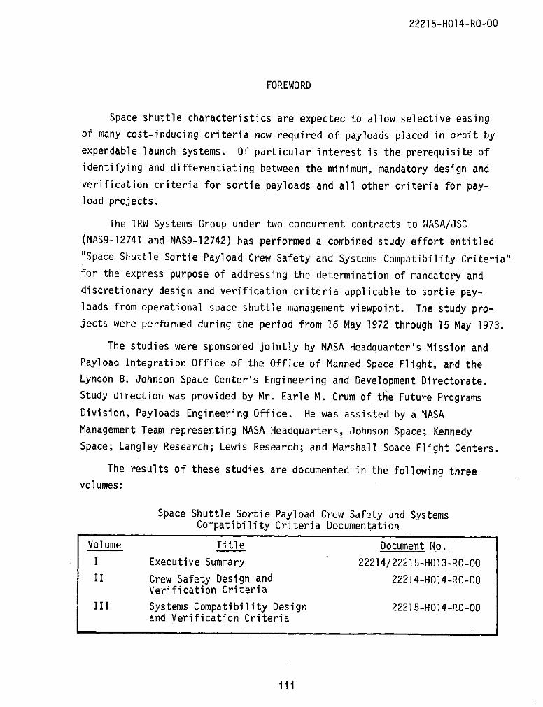
FOREWORD
Space shuttle characteristics are expected to allow selective easing
of many cost-inducing criteria now required of payloads placed in orbit by
expendable launch systems. Of particular interest is the prerequisite of
identifying and differentiating between the minimum, mandatory design and
verification criteria for sortie payloads and all other criteria for pay-load projects.
The TRW Systems Group under two concurrent contracts to NASA/JSC
(NAS9-12741 and NAS9-12742) has performed a combined study effort entitled
"Space Shuttle Sortie Payload Crew Safety and Systems Compatibility Criteria"for the express purpose of addressing the determination of mandatory anddiscretionary design and verification criteria applicable to sortie pay-loads from operational space shuttle management viewpoint. The study pro-jects were performed during the period from 16 May 1972 through 15 May 1973.
The studies were sponsored jointly by NASA Headquarter's Mission andPayload Integration Office of the Office of Manned Space Flight, and theLyndon B. Johnson Space Center's Engineering and Development Directorate.Study direction was provided by Mr. Earle M. Crum of the Future Programs
Division, Payloads Engineering Office. He was assisted by a NASA
Management Team representing NASA Headquarters, Johnson Space; KennedySpace; Langley Research; Lewis Research; and Marshall Space Flight Centers.
The results of these studies are documented in the following threevolumes:
Space Shuttle Sortie Payload Crew Safety and SystemsCompatibility Criteria Documentation
Volume Title Document No.I Executive Summary 22214/22215-H013-RO-00
II Crew Safety Design and 22214-HO14-RO-O0Verification Criteria
III Systems Compatibility Design 22215-H014-RO-O0and Verification Criteria
iii
22215-HO14-RO-00
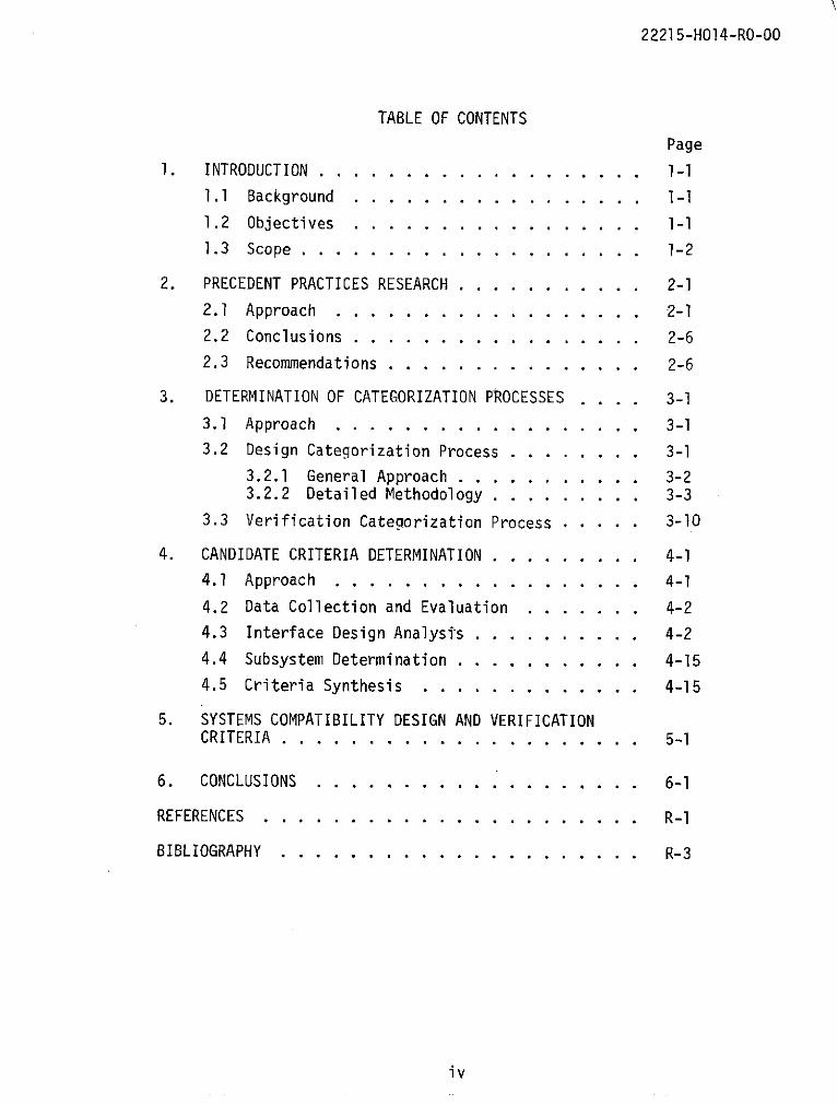
TABLE OF CONTENTS
Page
1. INTRODUCTION . . . . . . . . . . . . . . . . . . . 1-1
1.1 Background . . . . . . . . . . . . . . . . . 1-1
1.2 Objectives . . . . . . . . . . . . . . . . . 1-1
1.3 Scope . . . . . . . . . . . . . . . . . . . . 1-2
2. PRECEDENT PRACTICES RESEARCH . . . . . . . . . . . 2-1
2.1 Approach . . . . . . . . . . . . . . . . . . 2-1
2.2 Conclusions . . . . . . . . . . . . . . . . . 2-6
2.3 Recommendations . . . . . . . . . . . . . . . 2-6
3. DETERMINATION OF CATEGORIZATION PROCESSES .... 3-1
3.1 Approach . . . . . . . . . . . . . . . . . . 3-1
3.2 Design Categorization Process . . . . . . . . 3-1
3.2.1 General Approach . . . . . . . . . . . 3-23.2.2 Detailed Methodology . . . . . . . . . 3-3
3.3 Verification Categorization Process . . . . . 3-10
4. CANDIDATE CRITERIA DETERMINATION . . . . . . . . . 4-1
4.1 Approach . . . . . . . . . . . . . . . . . . 4-1
4.2 Data Collection and Evaluation . . . . . . . 4-2
4.3 Interface Design Analysis . . . . . . . . . . 4-2
4.4 Subsystem Determination . . . . . . . . . . . 4-15
4.5 Criteria Synthesis . . . . . . . . . . . . . 4-15
5. SYSTEMS COMPATIBILITY DESIGN AND VERIFICATIONCRITERIA . . . . . . . . . . . . . . . . .. . ... . 5-1
6. CONCLUSIONS . . . . . . . . . .. . . . . . . . . 6-1
REFERENCES . . . . . . . . . . . . . . . . . . ....... R-1
BIBLIOGRAPHY . . . . . . . . . . . . . . .. . . . . . R-3
iv
22215-HOI4-RO-00
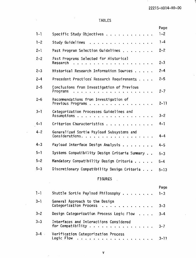
TABLES
Page
1-1 Specific Study Objectives ......... . .. 1-2
1-2 Study Guidelines . ............... 1-4
2-1 Past Program Selection Guidelines . ....... 2-2
2-2 Past Programs Selected for HistoricalResearch . . . . . . . . . . . . . . . . . .. . 2-3
2-3 Historical Research Information Sources ..... 2-4
2-4 Precedent Practices Research Requirements .... 2-5
2-5 Conclusions from Investigation of PreviousPrograms . . . . . . . . . . . . . . . . . .. . 2-7
2-6 Recommendations from Investigation ofPrevious Programs . ...... ... ....... 2-11
3-1 Categorization Processes Guidelines andAssumptions . . . . . . . . . . . . . . . . . . . 3-2
4-1 Criterion Characteristics . ........... 4-1
4-2 Generalized Sortie Payload Subsystems andConsiderations. . ................ 4-4
4-3 Payload Interface Design Analysis . ....... 4-5
5-1 Systems Compatibility Design Criteria Summary . 5-3
5-2 Mandatory Compatibility Design Criteria .... . 5-4
5-3 Discretionary Compatibility Design Criteria . . . 5-13
FIGURES
Page
1-1 Shuttle Sortie Payload Philosophy . ....... 1-3
3-1 General Approach to the DesignCategorization Process . ............ 3-3
3-2 Design Categorization Process Logic Flow . . . . 3-4
3-3 Interfaces and Interactions Consideredfor Compatibility ................ 3-7
3-4 Verification Categorization ProcessLogic Flow . . . . . . . . . . . . . . . . . . . 3-11

22215-HO14-RO-O0
NOMENCLATURE
AC Alternating Current
A/C Aircraft
AFSC Air Force Systems Command
ALSEP Apollo Lunar Surface Experiment Package
ARC Ames Research Center
ASP Airborne Science Program
ASPO Apollo Spacecraft Program Office
c.g. Center of Gravity
COMM Communications
CO2 Carbon Dioxide
CSM Command and Service Module
CV Convair
D Discretionary
DAC Douglas Aircraft Company
DC Direct Current
D&C Displays and Controls
DH Design Handbook
DOD Department of Defense
DP&S Data Processing and Software
ECLS Environmental Control and Life Support
ELEC Electrical
EMC Electromagnetic Compatibility
EMI Electromagnetic Interference
EOS Earth Orbiting Shuttle
ERAP Earth Resources Aircraft Program
EVA Extravehicular Activity
FOV Field-of-View
vi

22215-HOl4-RO-00
NOMENCLATURE (Continued)
g GravityGDCA General Dynamics Convair Aerospace DivisionGEN General
GFE Government Furnished Equipment
G&N Guidance and Navigation
GN&C Guidance, Navigation and Control
GSFC Goddard Space Flight Center
GSE Ground Support Equipment
HEAO High Energy Astronomical Observatory
HTS Heat Transport System
HV High Voltage
ICD Interface Control Document
INST Instrumentation
IVA Intravehicular Activity
JSC Johnson Space Center
KSC Kennedy Space Center
LM Lunar Module
LED LM Engineering Document
LEM Lunar Excursion Module
LSP LM SpecificationLV Low Voltage
M Mandatory
MIL Military
MOL Manned Orbiting Laboratory
MSC Manned Spacecraft Center
MSCM Manned Spacecraft Center Manual
vii
22215-HOI4-RO-O0
NOMENCLATURE (Continued)
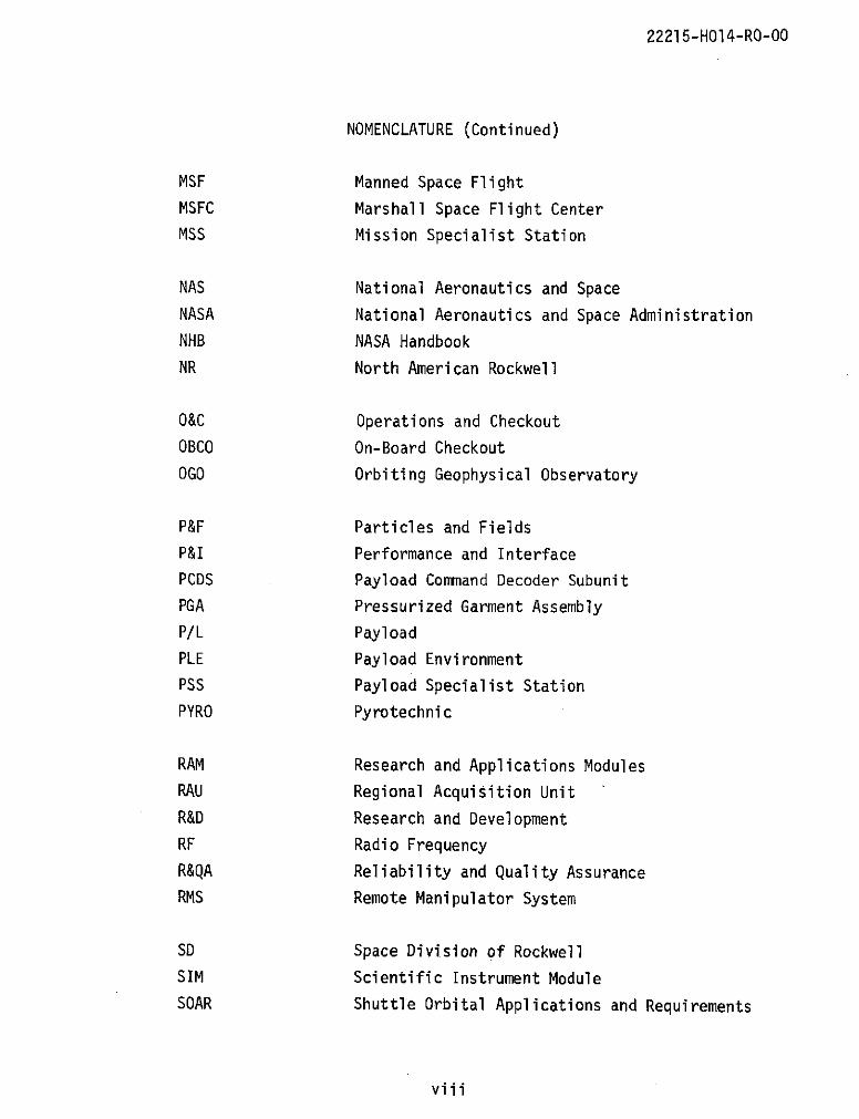
MSF Manned Space Flight
MSFC Marshall Space Flight Center
MSS Mission Specialist Station
NAS National Aeronautics and Space
NASA National Aeronautics and Space Administration
NHB NASA Handbook
NR North American Rockwell
O&C Operations and Checkout
OBCO On-Board Checkout
OGO Orbiting Geophysical Observatory
P&F Particles and Fields
P&I Performance and Interface
PCDS Payload Command Decoder Subunit
PGA Pressurized Garment Assembly
P/L Payload
PLE Payload Environment
PSS Payload Specialist Station
PYRO Pyrotechnic
RAM Research and Applications Modules
RAU Regional Acquisition Unit
R&D Research and Development
RF Radio Frequency
R&QA Reliability and Quality Assurance
RMS Remote Manipulator System
SD Space Division of Rockwell
SIM Scientific Instrument Module
SOAR Shuttle Orbital Applications and Requirements
viii

22215-HOI4-RO-O0
NOMENCLATURE (Concluded)
SP Special Publications
SPEC Specification
STD Standards
STRU Structures
TDDS TV Data Display Systems
THER Thermal
TM Technical Manual
TOR Technical Operating Report
TV Television
U Unclassified
VAC Vacuum
ix

22215-HOI4-RO-00
1. INTRODUCTION
1.1 BACKGROUND
NASA is currently examining shuttle payload costs in an effort to both
more accurately predict and reduce such costs. History indicates that the
criteria applied by NASA to previous space payloads caused them to be quite
expensive. This practice was acceptable considering the costs associated
with the launch and the necessity for a high probability of mission success.
However, when these costs are used to estimate the cost of future shuttle
payloads, it is evident that there would soon be a cost factor limiting
the use of the shuttle.
Fortunately, the shuttle characteristics will allow selectively easingmany of the cost-inducing criteria now placed on expendable launch system
payloads. Relaxing these criteria is expected to greatly reduce the costof space payload development.
Central to those cost-reducing efforts must be the capability to
identify and differentiate between the minimum, mandatory design and veri-fication criteria for shuttle sortie payloads and all other candidatecriteria for payload projects. Accordingly, this study will contribute tolower sortie payload costs by producing a methodology capable of definingthe minimum criteria required for a compatible sortie payload. Theresulting criteria will form the basis of future specifications to bedeveloped when quantitative shuttle data are available.
1.2 OBJECTIVES
The prime objective of this study was to identify the minimum, manda-
tory payload design and verification criteria necessary to insure that
sortie payloads are compatible with the space shuttle system, distinguishing
them from those criteria related to mission success, configuration choices
or management approaches which are, therefore, discretionary to payload
project management as variables in cost-benefit trades. Specific study
objectives are tabulated in Table 1-1.
1-1
22215-HO14-RO-00
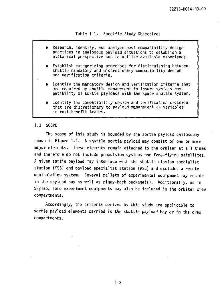
Table 1-1. Specific Study Objectives
* Research, identify, and analyze past compatibility designpractices in analogous payload situations to establish ahistorical perspective and to utilize available experience.
* Establish categorizing processes for distinguishing betweenshuttle mandatory and discretionary compatibility desianand verification criteria.
* Identify the mandatory design and verification criteria thatare required by shuttle management to insure systems com-patibility of sortie payloads with the space shuttle system.
* Identify the compatibility design and verification criteriathat are discretionary to payload management as variablesin cost-benefit trades.
1.3 SCOPE
The scope of this study is bounded by the sortie payload philosophyshown in Figure 1-1. A shuttle sortie payload may consist of one or moremajor elements. These elements remain attached to the orbiter at all timesand therefore do not include propulsion systems nor free-flying satellites.
A given sortie payload may interface with the shuttle mission specialist
station (MSS) and payload specialist station (PSS) and excludes a remote
manipulation system. Several pallets of experimental equipment may residein the payload bay as well as piggy-back package(s). Additionally, as inSkylab, some experiment equipments may also be included in the orbiter crewcompartments.
Accordingly, the criteria derived by this study are applicable tosortie payload elements carried in the shuttle payload bay or in the crewcompartments.
1-2

22215-HO14-RO-00
Piggy-Back AdditionalPSS Panels Package(s) Pallet(s)
-ijii LPalletA-
ExperimentEquipment(s)
Figure 1-1. Shuttle Sortie Payload Philosophy
Since sortie payloads are pre-phase A in development, a generalized
sortie payload was conceived against which an interface design analysis
could be made. This generalized payload model contains the subsystems,
instruments, and considerations known to be included in representative
sortie payloads and is defined in Section 4.
The basic guidelines employed in the study are summarized in Table 1-2.
1-3

22215-H014-RO-00
Table 1-2. Study Guidelines
* This study addresses the post R&D, operational shuttle era assuming amature, fixed-design, "shuttle airlines" flight operations capabilityoriented to low-complexity, low-cost operations.
* Design and test considerations include only those imposed by the spaceshuttle for mission purposes and are confined within the limits fromterminal countdown through a normal landing.
* Whether payload equipment is from the civilian sector or GFE should notalter the applicability of the shuttle imposed mandatory criteria. Thepayload should be given maximum possible latitude.
* Extravehicular activity (EVA) requirements are not excluded from asortie payload. However, shuttle EVA equipment are excluded fromassignment to the payload.
* Study definitions:
- Criteria are general rules by which the acceptability of shuttlepayloads may be determined.
- Specifications are the translations of criteria into explicit,usually quantitative, statements suitable for detailed design andtest purposes. A criterion may translate into several specifications.
- Requirements may be criteria or specifications which have been im-posed by appropriate administrative authority.
- Orbiter/payload interface is a point (or area) where a physicalrelationship exists between the orbiter and payload, or betweenmajor payload elements, wherein physical and/or functional compat-ibility is required.
- Systems compatibility involves those payload interface design featuresthat must be satisfied so that the payload elements and the orbitercan function together within acceptable degrees of mutual tolerance.Compatibility between payload elements is defined to encompass thesame considerations as those between the payload and the orbiter.
- Mandatory systems compatibility design criteria and verificationlevels are defined, levied and controlled by shuttle management andare obligatory to all sortie payload elements. However, certain ofthese criteria that affect only the payload may be controlled bypayload management.
- Discretionary design criteria make up all other criteria. Implemen-tation and verification of these criteria are subject to payloadproject management prerogatives.
1-4

22215-H014-RO-00
2. PRECEDENT PRACTICES RESEARCH
An investigation of past practices in spacecraft and aircraft programs
was accomplished to establish a historical perspective and a baseline of
information in the form of conclusions and recommendations applicable to
this study.
2.1 APPROACH
The basic standard for selection of programs for investigation was
that they be analogous to the shuttle-payload situation. This basic stan-
dard was expanded into a set of guidelines to be used in the selection of
past programs. Table 2-1 itemizes these guidelines and indicates the
rationale or analogy to the shuttle for each guideline.
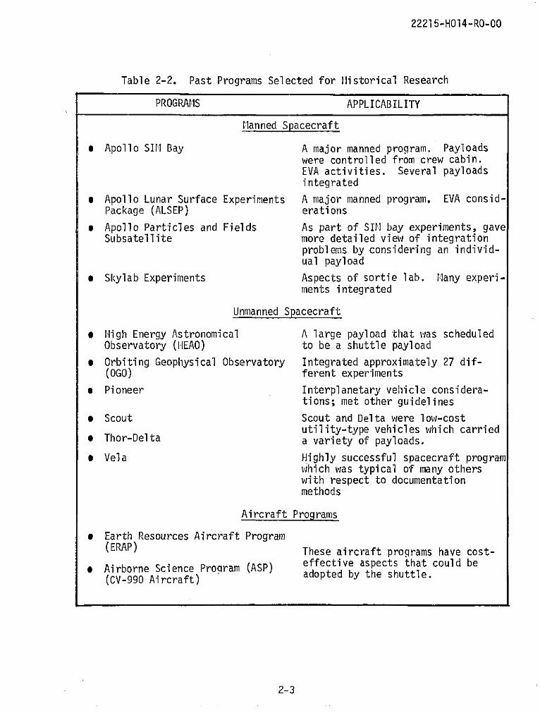
A wide variety of programs were selected based upon the guidelines.
Twelve programs were addressed and are presented in Table 2-2 along with
comments on their applicability. Although not considered as past programs,
two shuttle-related study reports, Research and Applications Module (RAM)
and Shuttle Orbital Applications and Requirements (SOAR) studies
(References 1 and 2), were provided by NASA to give current perspective
concerning some sortie payloads, payload integration and other pertinent
planning details. These programs and studies were considered to cover an
adequate cross section of applicable programs necessary to obtain a com-
prehensive understanding of the practices, procedures, and methods of
analogous programs.
Utilizing the available information sources shown in Table 2-3, a plan
was formulated for researching the selected programs. This plan consisted
of a series of requirements, shown in Table 2-4, obtained from each of the
selected programs. These requirements, along with appropriate documenta-
tion, provided a comprehensive insight as to how the compatibility problem
was handled on these programs. In addition, a basis for recommending those
past practices and procedures which should not be carried forward into the
shuttle era was established.
2-1

22215-H014-RO-00
Table 2-1. Past Program Selection Guidelines
* Programs were either manned - Shuttle is a manned program. Payloadsor unmanned. were integrated onto unmanned programs
as will be done on shuttle. Further,many techniques of unmanned programsmay be applicable to the shuttle.
* Payload carrier was an - The shuttle is a spacecraft but hasaircraft or spacecraft. many of the attributes and charac-
teristics of aircraft.
* Payload was a scientific - Shuttle payloads, for the most part,experiment. will be scientific in nature.
* Preferable that the carrier - The shuttle will carry a variety ofvehicle accommodated several independent payloads.independent payloads.
* Carrier vehicle levied com- - The shuttle will require that pay-patibility requirements on loads be compatible with the shuttlethe payloads. vehicle.
* Select the most recent and - It was not feasible to research allmost accessible of the past programs; the most recent programsprograms. provide the latest technology.
2-2
22215-HO14-RO-00
Table 2-2. Past Programs Selected for Historical Research
PROGRAMS APPLICABILITY
Manned Spacecraft
* Apollo SIM Bay A major manned program. Payloadswere controlled from crew cabin.EVA activities. Several payloadsintegrated
* Apollo Lunar Surface Experiments A major manned program. EVA consid-Package (ALSEP) erations
* Apollo Particles and Fields As part of SIN bay experiments, gaveSubsatellite more detailed view of integration
problems by considering an individ-ual payload
* Skylab Experiments Aspects of sortie lab. Many experi-ments integrated
Unmanned Spacecraft
* High Energy Astronomical A large payload that was scheduledObservatory (HEAO) to be a shuttle payload
* Orbiting Geophysical Observatory Integrated approximately 27 dif-(OGO) ferent experiments
* Pioneer Interplanetary vehicle considera-tions; met other guidelines
* Scout Scout and Delta were low-costutility-type vehicles which carried
* Thor-Delta a variety of payloads.
* Vela Highly successful spacecraft programwhich was typical of many otherswith respect to documentationmethods
Aircraft Programs
* Earth Resources Aircraft Program(ERAP) These aircraft programs have cost-SAirborne Science Program (ASP) effective aspects that could be
(CV-990 Aircraft) adopted by the shuttle.
2-3

22215-HOI4-RO-O0
Table 2-3. Historical Research Information Sources
DATA SOURCE PROGRAM
NASA
Johnson Space Center
Engineering and Development ALSEP (3, 4)*, Apollo SIM BayDirectorate Experiments (5), ERAP (6), RAM
(1), SOAR (2)
Skylab Program Office Skylab Experiments (7)
Ames Research Center ASP (CV-990) (8)
Langley Research Center Scout (9)
Marshall Space Flight Center Skylab Experiments (7), Shuttle(10)
Contractors
North American Rockwell Apollo SIM Bay Experiments (5)
McDonnell Douglas Corporation Thor-Delta (11, 12), Shuttle (13)
Vought Missiles and Space Company Scout (9)
Boeing Aerospace Skylab Experiments (7)
TRW OGO (14), Pioneer (15, 16),Vela (17, 18), HEAO (19),P&F Subsatellite
Documentation(Other than from above sources)
Aerospace Corporation Shuttle (20)
Lockheed Missiles and Space Shuttle (21)Corporation
Grumman Aerospace Corporation ALSEP (22)
*Documentation references in parentheses
2-4

22215-H014-RO-00
Table 2-4. Precedent Practices Research Requirements
1. Determine the criteria used to write payload design specificationsthat were placed upon experimenters to assure compatibility. If notavailable, obtain payload specifications. Determine the rationaleor justification for implementing each criterion or specification.
2. Determine the payload testing criteria or specifications used toachieve design compatibility with the payload carrier vehicle or withother payloads.
3. Determine the payload design and test criteria or specificationsdesignated as mandatory. Determine the guidelines used to classifythese criteria as mandatory.
4. Which of these design and test criteria or specifications were relaxedor revised from their original requirement as problems arose in orderto meet the compatibility requirement? What was the original require-ment and what caused the change?
5. Determine which criteria or specifications resulted in high productionor testing costs with respect to overall costs.
6. Determine the significant payload integration problems and how theywere solved. This includes both payload-to-vehicle and payload-to-payload compatibility problems.
7. Determine how successful the payloads were and if any failures weredue to integration problems.
8. Determine the criteria and philosophy concerning off-the-shelf orstandard components used in the payloads.
2-5
22215-H014-RO-00
2.2 CONCLUSIONS
Conclusions from the historical research effort evolved into statements
which applied to one or more of the programs investigated. These statements,
itemized in Table 2-5, represent a summary of the information gained from
the research requirements and the documentation that was reviewed. From
these conclusions, recommendations for application to subsequent study re-
quirements were formulated.
An additional result of the historical research was an accumulation of
specifications, requirements, guidelines, and criteria utilized by these
programs to guide payload development and integration. This accumulation
became the baseline for sortie payload criteria determination and develop-
ment which is discussed in Section 4.
2.3 RECOMMENDATIONS
The recommendations resulting from the analysis of past practices,
shown in Table 2-6, were presented to and approved by the NASA Management
Team at the study formal mid-term review. Where applicable, the recommen-
dations were formulated employing the terminology of the study. They were
geared toward being utilized as a baseline for the development of design
and verification criteria as well as the categorization processes (see
Section 3) that were developed to distinguish between mandatory and dis-
cretionary criteria. Therefore, each recommendation is reflected in the
categorization processes, in the manner criteria were developed, or in
philosophies which would contribute to overall cost reduction of payloads
in the shuttle era.
2-6

Table 2-5. Conclusions from Investigation of Previous Programs
PROGRAMS
MANNED UNMANNED AIR-SPACECRAFT SPACECRAFT BORNE
CONCLUSIONS "
the past resulted in successful programs.the payloads on first attempt. For this reason,
. Procedures, methods, philosophy, etc., utilized in X X X X X X Xcom-the past resulted in successful programs.
2. Programs had "one-chance" to assure that payloadswere compatible with the spacecraft; therefore, pre-vious practices were geared toward mission success of X X X X X X X X X X
the payloads on first attempt. For this reason,functional requirements were not separated from com-
patibility design and verification requirements.
3. Common practice is for NASA to fly only equipment X X X X X X X X X X X
that meets all government specifications.
4. Experimenters were supplied with guiding documents
(such as P&I specs, ICD's, or handbooks) which gave X X X X X X X X X X X Xdesign and test requirements to various levels of de-tail with the type of program determining this level.
5. The number of payload requirements and specificationslevied were directly proportional to the cost ofpayload delivery. L,
* Highest Complexity: MSF & Interplanetary Programs X X X X X o
* Lower Complexity: Unmanned Programs X X X
9 Lowest Complexity: A/C and Certain Unmanned X X X XPrograms
o
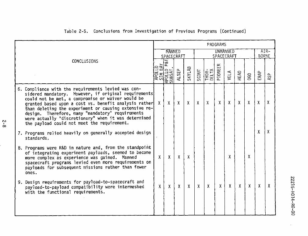
Table 2-5. Conclusions from Investigation of Previous Programs (Continued)
PROGRAMS
MANNED UNMANNED AIR-SPACECRAFT SPACECRAFT BORNE
CONCLUSIONS
0 -QC co _ L-) LU LU LU CM i= V)
6. Compliance with the requirements levied was con-sidered mandatory. However, if original requirementscould not be met, a compromise or waiver would be
granted based upon a cost vs. benefit analysis rather X X X X X X X X X X X X
than deleting the experiment or causing extensive re-design. Therefore, many "mandatory" requirementswere actually "discretionary" when it was determinedthe payload could not meet the requirement.
7. Programs relied heavily on generally accepted design X X
standards.
8. Programs were R&D in nature and, from the standpointof integrating experiment payloads, seemed to becomemore complex as experience was gained. Manned X X X X X Xspacecraft programs levied even more requirements onpayloads for subsequent missions rather than fewerones.
9. Design requirements for payload-to-spacecraft and
payload-to-payload compatibility were intermeshed X X X X X X X X X X X X
with the functional requirements.
Co
I__o
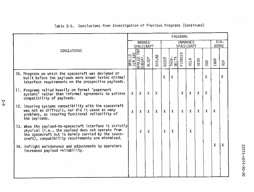
Table 2-5. Conclusions from Investigation of Previous Programs (Continued)
PROGRAMS
MANNED UNMANNED AIR-SPACECRAFT SPACECRAFT BORNE
CONCLUSIONSC) <: co LU
CD J ) > C) CD C) -- C
<oI ) Ul) a_ =-C C > V C) LU
10. Programs on which the spacecraft was designed orbuilt before the payloads were known levied minimal X X X X
interface requirements on the prospective payloads.
11. Programs relied heavily on formal "paperwork
systems" rather than informal agreements to achieve X X X X X X X X
compatibility of payloads.
12. Insuring systems compatibility with the spacecraftwas not as difficult, nor did it cause as many X X X X X X X X X X Xproblems, as insuring functional reliability ofthe payloads.
13. When the payload-to-spacecraft interface is strictlyphysical (i.e., the payload does not operate from X X X X Xthe spacecraft but is merely carried by the space-craft), compatibility requirements are minimized.
14. Inflight maintenance and adjustments by operators X X
increased payload reliability.0I
o
I
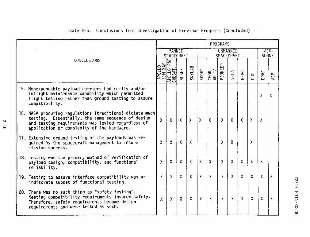
Table 2-5. Conclusions from Investigation of Previous Programs (Concluded)
PROGRAMS
MANNED UNMANNED AIR-SPACECRAFT SPACECRAFT BORNE
CONCLUSIONS
orJ) 1.) V > C) I- C - o C)
15. Nonexpendable payload carriers had re-fly and/orinflight maintenance capability which permitted X Xflight testing rather than ground testing to assurecompatibility.
16. NASA procuring regulations (traditions) dictate muchtesting. Essentially, the same sequence of design X X X X X X X X X X Xand testing requirements was levied regardless ofapplication or complexity of the hardware.
17. Extensive ground testing of the payloads was re-quired by the spacecraft management to insure X X X X X X Xmission success.
18. Testing was the primary method of verification ofpayload design, compatibility, and functional X X X X X X X X X X Xreliability.
19. Testing to assure interface compatibility was an X X X X X X X X X X Xindiscrete subset of functional testing.
20. There was no such thing as "safety testing".Meeting compatibility requirements insured safety. X X X X X X X X X X X XTherefore, safety requirements became designrequirements and were tested as such. o
o_ _ _ _ _ _ _ _ _ _ _ _ _ _ _ _ _ _ _ _ - - - - - - - - - - - - - - - - - - - - - - -

22215-H014-RO-00
Table 2-6. Recommendations from Investigation of Previous Programs
CONCLUSIONRECOMMENDATIONS REFERENCES
1. The following recommendations should be considered 1prefaced with the phrase "In order to minimize theoverall cost of shuttle payloads..." because pastmethods were successful and a prime reason for changeis to reduce costs.
3, 4, 6,2. Minimize and standardize requirements, criteria, 7, 8, 10
guidelines, etc., imposed by the space shuttle onexperimenters who design and test payloads.
3, 4, 5,3. Shuttle payload design and verification criteria 6, 7, 9,should be stated in general terms and mandatory 10requirements should be minimal.
4. Since shuttle will not be in a "one chance for 2,success" situation with respect to payloads, cri-teria and requirements once considered mandatoryshould be evaluated in a different perspective.
2, 95. Criteria levied on payloads by the orbiter to assure
compatibility should be distinguishable from thosecriteria levied to assure payload reliability orcrew safety.
2, 96. Compatibility criteria should also be further dis-
tinguishable as either mandatory or discretionaryto shuttle management.
10, 12,7. Mandatory compatibility design criteria levied on 13space shuttle payloads should be only those thatare imposed by the shuttle management and involvea payload-orbiter or payload-payload interface orinteraction. They are the minimum criteria whichpermit the payload to operate in the orbiter with-out causing unacceptable interference with theoperations or performance of the orbiter or anotherpayload. Typically, mandatory criteria should notbe waiverable or subject to negotiation.
16, 17, 18,8. Mandatory compatibility verification criteria should 19, 20be required by shuttle management only for mandatorydesign criteria. However, every mandatory designcriteria should not necessarily require a test forverification. Another verification method maysuffice.
2-11

22215-HOI4-RO-O0
Table 2-6. Recommendations from Investigation of PreviousPrograms (Concluded)
CONCLUSIONRECOMMENDATIONS REFERENCES
9. Rely on past experience to reduce the number and 10, 12, 13,severity of mandatory design and verification 16, 17, 18,criteria and stress methods of design verification 19, 20other than testing such as:
* Similarity * Inspection* Analysis * Demonstration
Experience plus intentional overdesign of interfaces(where economical and commensurate with orbitercapabilities) will eliminate much testing.
10. Discretionary compatibility design criteria give 6payload program management additional assurancethat payload reliability or operation is enhancedabove a minimum acceptable level and may be madeas a result of cost-benefit analyses.
11. Discretionary verification criteria are those levied 6to give additional assurance (above some minimumacceptable level that another verification methodwould give) that a design feature is acceptable.
12. Summarily, mandatory compatibility criteria should 3, 4, 5,be levied by JSC shuttle management and discretionary 6criteria levied by payload management.
2-12

22215-H014-RO-00
3. DETERMINATION OF CATEGORIZATION PROCESSES
The objective of categorization processes determination was to develop
tools which could be utilized to 1) determine if a candidate design criterion
was part of the minimum, mandatory set or the discretionary set for systems
compatibility, 2) generate a rationale to support the determination, and 3)
determine the minimum acceptable verification method for a mandatory crite-
rion. Two processes were developed. The first to be discussed, the design
categorization process, was structured to utilize the boundaries of the
study to systematically determine those criteria which are the minimum re-
quired for systems compatibility. These mandatory criteria are distinguished
by the process from all other criteria because they are required for nominal
payload/orbiter operation. The other methodology, the verification process,
was structured to determine the minimum level of verification necessary to
verify a mandatory design criterion. The remainder of this section details
the general approach utilized in this development along with specific and
detailed descriptions of the processes.
3.1 APPROACH
A "logic tree" methodology consisting of a series of analytical ques-tions was utilized for formulating the categorization processes. Theprocesses were developed based upon guidelines and assumptions which werederived from analysis of the objectives and scope of the study, PrecedentPractices Research recommendations, and other NASA recommendations anddirectives. Table 3-1 itemizes these basic guidelines and assumptionswhich, in addition to the general Study Guidelines in Table 1-1, arereflected in the structure and statements within the processes.
3.2 DESIGN CATEGORIZATION PROCESS
The objective of the design categorization process was to systemati-cally determine for each candidate sortie payload criterion whether it ismandatory or discretionary with respect to systems compatibility. Thefollowing subsections detail the approach and results of this methodology.
3-1

22215-H014-RO-00
Table 3-1. Categorization Processes Guidelines and Assumptions
Design Process
* Orbiter design remains fixed and the design criteria generated fromthe study will only affect payload design. Payload operationprocedures will not be considered applicable to the study.
* Compatibility design criteria involve interfaces and interactionsbetween the orbiter and the payload.
* The processes should apply to payloads already developed as well asthose that will be developed in the future.
* The orbiter management will levy mandatory design criteria uponpayload projects that will ensure payload and orbiter compatibilityfor nominal operations.
* Compatibility design criteria levied to prevent or circumvent acontingency or non-nominal situation will not be considered mandatory.These types of criteria will be either discretionary compatibilityor crew safety criteria.
Verification Process
* The verification process will determine if a design criterion mustbe verified by test or by another method of verification.
* The shuttle program management will require some verification levelof all mandatory design criteria.
* Shuttle program management will not require verification of discretion-ary design criteria.
* Commensurate with accumulated manned space flight (MSF) experience,verification techniques other than testing will be emphasized toreduce costs.
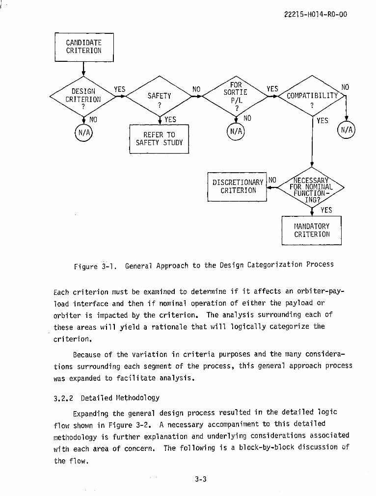
3.2.1 General Approach
The logic diagram approach to structuring the design process is shownin Figure 3-1. Each diamond represents a significant aspect to the overallcategorization problem. The first three steps of the methodology willdetermine if a criterion affects payload design, is applicable to a sortiepayload, and if the criterion is crew safety oriented. These steps aresomewhat straightforward but are necessary to meet overall study objectivesand eliminate criteria that have previously been imposed but are not partof the minimum set of criteria for basic compatibility. The remaining areasof concern require more extensive analysis.
3-2
22215-H014-RO-00
CANDIDATECRITERION
FORDESIGN YES NO SORTIE YES NOSAFETY P COMPATIBILITYCRITERION P/L
NO YES NO YES
N/A REFER TO N/A N/A
SAFETY STUDY
DISCRETIONARY NO 4ECESSARYCRITERIONFOR NOMINALCRITERION FUNCTION-
ING?YES
MANDATORYCRITERION
Figure 3-1. General Approach to the Design Categorization Process
Each criterion must be examined to determine if it affects an orbiter-pay-
load interface and then if nominal operation of either the payload or
orbiter is impacted by the criterion. The analysis surrounding each of
these areas will yield a rationale that will logically categorize the
criterion.
Because of the variation in criteria purposes and the many considera-
tions surrounding each segment of the process, this general approach process
was expanded to facilitate analysis.
3.2.2 Detailed Methodology
Expanding the general design process resulted in the detailed logic
flow shown in Figure 3-2. A necessary accompaniment to this detailed
methodology is further explanation and underlying considerations associated
with each area of concern. The following is a block-by-block discussion of
the flow.
3-3

1 2 3 13
IS THE CRITERION IS THE PRIMRY REASON DISCRETIONARYDOES THE CRITERION FOR THIS CRITERION TOCANDIDATE APPLICABLE TO TE ESPAYLOAD YES REDUCE A CREW HAZARD YES REFER TO SAFETY
CRITERION PAYLOAD CLASS UNDER POSSIBILITY AS DE- STUDY FOR ANALYSISDESIGN FACTORS? FINED BY THE GUIDE-
CONSIDERATION? LINES?
N 4 NO No
NOT APPLICABLE - DOES THE CRITERION YES NO 12
CANDIDATE FOR FUTURE REFLECT OR ANTICIPATE YES IS A CREW HAZARD POSSIBLE
NASA STUDY A C INGENCY IF THE CRITERION IS NOT
SITUATION? STISFIED?
NOI YES 6 NO
DES THE CRITERION REFLECT OR INVOLVE ANY OF THE COMPATIBILITY INTERFACES OR INTERACTIONS
* ORBITER . ORBITER- * MISSION-IN- * PAYLOAD- * PAYLOAD 8(INC. CREW) INDUCED EN- DUCED NATURAL INDUCED EN- ENVELOPE OR DOES THE CRITERION
PAYLOAD SUB- VIRONMENT OR ENVIRONMENT VIRONMENT OR MASS PROPERTIES ADDRESS PRIMARILY THE
SYSTEM SUP- CHARACTERISTIC CHARACTERISTIC CHARACTERISTIC OPERATION OF THE
PORT ELEMENT OR PROVISION ORBITER OR THE PAYLOAD?
PAYLOAD ORBITER
9 10
COULD THE PAYLOAD 11 COULD THE ORBITER
FUNCTION NOMINALLY IF NOFUNTIO NMINALLYTHE CRITERION WERE NOT THE CRITERION WRE NOT
SATISFIED? SATISFIED?
I
I
Figure 3-2. Design Categorization Process Logic Flow

22215-H014-RO-00
Block 1: Is the criterion applicable to the payload class under considera-
tion?
A basic consideration of this study was that the design process and
criteria development would consider only sortie payloads. The study
definition of sortie payloads (discussed in Section 1.3) was utilized as
the basis for the analysis. Specific hardware considerations precluded
from investigation in this study were payloads with propulsive or kick
stages, free-flyer payloads, and other ejected payloads.
Block 2: Does the criterion affect payload design factors?
A basic tenet of this study is that the criteria will be used as a
basis for writing design specifications for payloads. This question is
directed toward assuring that the criterion, in fact, affects payload
design rather than indicating how the payload will be operated or other
procedural considerations. If the criterion in question does not affect
a design factor, it is not considered applicable to this study because it
would lie outside the minimum mandatory set and therefore would increase
mandatory compatibility costs. As shown by Block 4, the criterion is re-
tained for possible future NASA use.
Block 3: Is the primary reason for this criterion to reduce a crew hazard
possibility as defined by the guidelines?
The study was directed solely at criteria utilized for the purpose of
assuring systems compatibility and not crew safety. The purpose of this
question is to eliminate all criteria that are obviously safety oriented
and to refer them to the associate Crew Safety Study (NAS9-12742) as
directed by Block 5. Criteria context will indicate, in most cases, if the
primary reason is to protect the crew from a hazard. The process has pro-
visions in later stages to identify subtle safety criteria or those that
were questionably safety oriented and permitted to proceed for further
analysis.
3-5

22215-HO14-RO-O0
Block 6: Does the criterion reflect or involve any of the compatibility
interfaces?
* Orbiter (including crew) payload-subsystem support element
* Orbiter-induced environment or characteristic
* Mission-induced or natural environment
* Payload-provided provisions for the interface
* Payload-induced environment or characteristic
* Payload envelope or mass properties characteristic
A guideline of the compatibility study was that compatibility criteria
involve interfaces and interactions. Compliance with this guideline con-
tributes to the limitation of the mandatory compatibility criteria popu-
lation and therefore to the reduction of payload integration costs. An
analysis of this guideline prompted the considerations shown in Figure 3-3.
Analysis of these factors, as the following paragraphs explain, resulted
in the structure of the Block 6 question.
The orbiter will provide support elements to the payload such as
electrical, physical attachment, and pointing/stabilizing which the pay-
load can utilize if necessary. These support features provide an inter-
face between the orbiter and the payload that affects payload/orbiter
operation and must be considered in payload design.
Within these support elements are intrinsic characteristics which
the payload must tolerate to assure proper payload operation. For example,the payload must be designed to tolerate electrical support transient
characteristics. Physical attachment support includes characteristics
such as shock and vibration which the payload design must tolerate.
The payload will be subjected to environmental factors from the orbiter
and from natural or mission-induced sources intrinsic to the space environ-
ment. The orbiter will induce environments such as radiation, magnetic
fields, and other potentially undesirable elements of which the payload
designers must be made aware to assure proper payload operation. Similarly,
natural or mission-induced environments such as low gravity and pressure,
meteoroid impact, and atmospheric contamination must be considered.
3-6

22215-H014-RO-00
The payload will also be required to provide accommodations to assure
that the payload-orbiter interface is complete. A case in point is pay-
loads requiring EVA to complete mission operations. Special tools or
mobility aids must be provided as necessary. The payload will also be
required to provide certain instrumentation such as recorders and special
display equipment. These payload-provided equipments will interface with
the orbiter and must be specified so that proper interface design is
assured.
PAYLOAD
MISSION ENVIRONMENTS
ORBITER
Figure 3-3. Interfaces and Interactions Consideredfor Compatibility
Assuring compatibility is a two-sided coin. Not only must efforts be
directed toward assuring proper payload operation, but equal concentration
must be made to assure that orbiter operations are not impaired by omitting
certain payload criteria. These criteria fall into the general category of
3-7

22215-HO14-RO-00
criteria which are ofter called "hardware safety" criteria or requirements.
This study addresses a subset of that category; specifically, those criteria
levied on payloads to assure that nominal orbiter operations are not im-
pared by the payload. Typically, these criteria involve vehicle operations
interference resulting from support interface with the payload. Also, nomi-
nal vehicle operation rather than crew safety is of first concern in thesecriteria. (Volume II of this study addresses that aspect of "hardware
safety" criteria where each criterion involves crew safety as the prime
consideration). Payload-induced characteristics and environments such assize, weight, and payload-generated contamination are examples of criteria
elements pertinent to this category of criteria and must be considered for
systems compatibility.
Utilizing the considerations of Block 6 will determine if a given
criterion is, in fact, an applicable candidate compatibility criterion.
Criteria not falling into one of these compatibility categories are not
applicable to this study and are retained for future NASA use.
Block 7: Does the criterion reflect or anticipate a contingency situation?
A primary objective of this study is to determine the minimum, manda-
tory set of compatibility criteria. In doing so, prime consideration is
given to those design features that assure only basic compatibility of an
interface thereby bounding minimum costs. This means the minimum criteria
necessary for nominal operation and functioning of the payload or the
orbiter through the interface are of major concern. Then, all supplemen-
tary design features that are cost-benefit in nature can be levied at the
discretion of management to avoid possible problems or abnormal influences
that could impact operations. These criteria either assure crew safety
or enhance payload performance or mission success. Criteria of this type
receive a "YES" to the Block 6 question and are passed on to Block 12 for
further analysis. Those criteria which receive a "NO" may be mandatoryfor compatibility and are passed to Block 8 for analysis.
3-8

22215-HOl4-RO-00
Block 8: Does the criterion address primarily the operation of the orbiter
or the payload?
This branching block is utilized to determine which side of the orbi-
ter-payload interface is being primarily affected so that further, more
detailed analysis can be made.
Blocks 9 and 10: Could the payload/orbiter function nominally if thecriterion were not satisfied?
The most appropriate test for determining if a candidate criterion
is mandatory is to analyze the consequence of not imposing the criterion.If not imposing the criterion could prevent nominal, planned operation ofeither the payload or the orbiter, the criterion must be considered manda-tory for systems compatibility and go to Block 11. Criteria which receivea "YES" to this question are not considered mandatory and pass to Block 12for further analysis.
Block 12: Is a crew hazard possible if the criterion is not satisfied?
One of the initial steps in this process (Block 3) checked for
obvious safety criteria. Block 12 provides for another check so that,
after analysis, those criteria that emerge as subtle safety oriented canbe referred to the Safety Study for further analysis.
Block 13: Discretionary
The final block of the design process describes discretionary criteria--
those criteria subject to cost-benefit analysis. Criteria which reach this
point in the process are discretionary to shuttle management and involvethe following considerations:
* Configuration choices of components, assemblies, systems, etc.,
not required to assure compatibility
@ Enhancement of payload mission success probability over and
above that provided by basic systems compatibility
* Enabling payload performance at levels which would exceed
the performance levels dictated by baseline orbiter accommodations
* Other cost-benefit trades
3-9

22215-HO14-RO-O
This area completes the analysis of a candidate design criterion. As
mentioned at the beginning of the design process discussion, an additional
requirement of the process is to produce a rationale with each categoriza-tion determination. This is accomplished by documenting the path each
criterion takes through the process. The analysis surrounding each block
to which the criterion is subjected then becomes the rationale that supports
the final categorization.
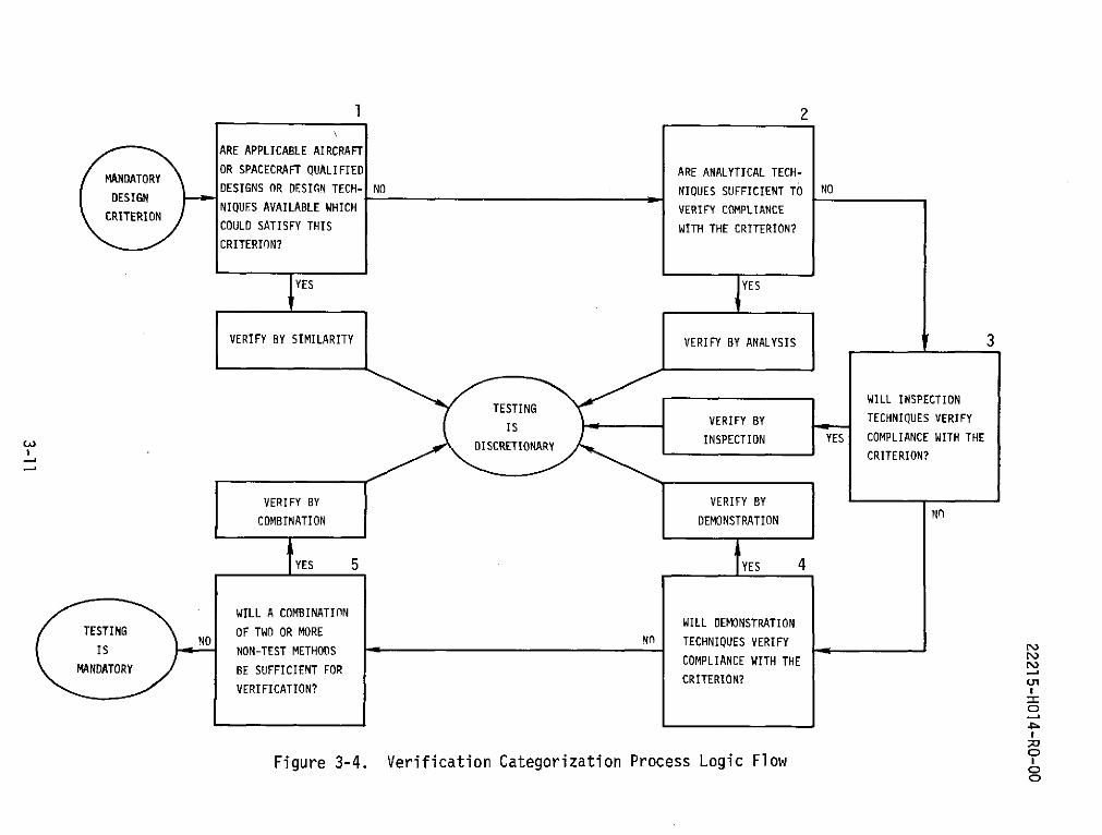
3.3 VERIFICATION CATEGORIZATION PROCESS
The objective of verification is to assure shuttle management that
the payload has complied with a mandatory design criterion. The verifica-tion process determines for each mandatory design criterion which verifica-
tion technique is considered sufficient by shuttle management as minimum,mandatory design verification. In light of past spaceflight experiencecoupled with the capabilities and low-cost objectives of the shuttle,
verification methods other than testing can and should be emphasized.This is accomplished, as shown in Figure 3-4, by systematically analyzing
the mandatory design criterion.to determine if one of the other standardverification methods (similarity, analysis, inspection, demonstration)
will suffice. Utilization of these other verification methods is not new,(References 6 and 7); however, as brought out here and in the recommenda-
tions from Precedent Practices Research, with the experience already obtainedfrom space flight, employment of these methods to a greater extent shouldbe possible. Since these methods are generally less costly to apply thantesting, an overall cost-savings can be realized.
If the verification method determined is other than testing, then
testing to verify the criterion is considered discretionary. Testing may
be performed at the discretion of payload management to further substan-
tiate the adequacy or reliability of the design. The following is a
detail.ed explanation of each of the verification methods specified in
Figure 3-4.
3-10
1 2
ARE APPLICABLE AIRCRAFT
OR SPACECRAFT QUALIFIED ARE ANALYTICAL TECH-
DESIGNS OR DESIGN TECH- NO NIQUES SUFFICIENT TO NODESIGNCRITERION NIQUES AVAILABLE WHICH VERIFY COMPLIANCE
COULD SATISFY THIS WITH THE CRITERION?
CRITERION?
YES YES
VERIFY BY SIMILARITY VERIFY BY ANALYSIS _ 3
WILL INSPECTION
VERIFY BY TECHNIQUES VERIFYIS
DISCRETIONARY INSPECTION YES COMPLIANCE WITH THE
CRITERION?
VERIFY BY VERIFY BY
COMBINATION DEMONSTRATION NO
YES 5 IYES 4
WILL A COMBINATION
TESTING OF TWO OR MORENO TWO OR MORE NO TECHNIQUES VERIFY r
IS NON-TEST METHODSCOMPLIANCE WITH THE
MANDATORY BE SUFFICIENT FORCRITERION?
VERIFICATION?
Figure 3-4. Verification Categorization Process Logic Flow

22215-H014-RO-00
Block I: Similarity
Verification by similarity is used when the article or payload is
substantially similar or identical in design, manufacturing processes, and
quality control to another article that has been previously qualified to
equivalent or more stringent standards. Verification by similarity may
pertain to characteristics such as material, configuration, functional
element or assembly. As indicated by the JSC R&QA Office Test Section,
for example, equipment verified for flight on manned aircraft (such as the
ERAP program) could be sufficiently qualified by similarity for spaceflight.
Block 2: Analysis
Analysis may be used in lieu of testing whenever it can be shown by
generally accepted analytical techniques that an article will meet the
applicable technical requirements. Increased design margins, made possible
by shuttle weight and volume capabilities, will allow verification by
analysis where testing was previously required.
Block 3: Inspection
Inspection can be used to verify the construction features, compliance
with drawings, workmanship, and physical condition of the article. This
method is utilized at design reviews and customer acceptance readiness
reviews to verify design requirements.
Block 4: Demonstration
Demonstration can be used to verify such requirements as service and
access, handling, convenience, and ease of operation. This method is used
extensively in verifying designs that involve a man-machine interface such
as crew-payload interface during EVA activities.
Block 5: Combination
Verification by combining two or more of the previously discussed
methods may be utilized if one method does not provide minimum acceptable
verification.
If these verification methods are not sufficient to verify a mandatory
design criterion, then testing must be employed as the verification method.
3-12
22215-HOl4-RO-00
4. CANDIDATE CRITERIA DETERMINATION
The objective of this portion of the study was to identify, define,
and structure compatibility design criteria which would be subjected to
the categorization process, discussed in Section 3, for categorization as
either mandatory or discretionary. The following subparagraphs discuss
the approach taken in this effort.
4.1 APPROACH
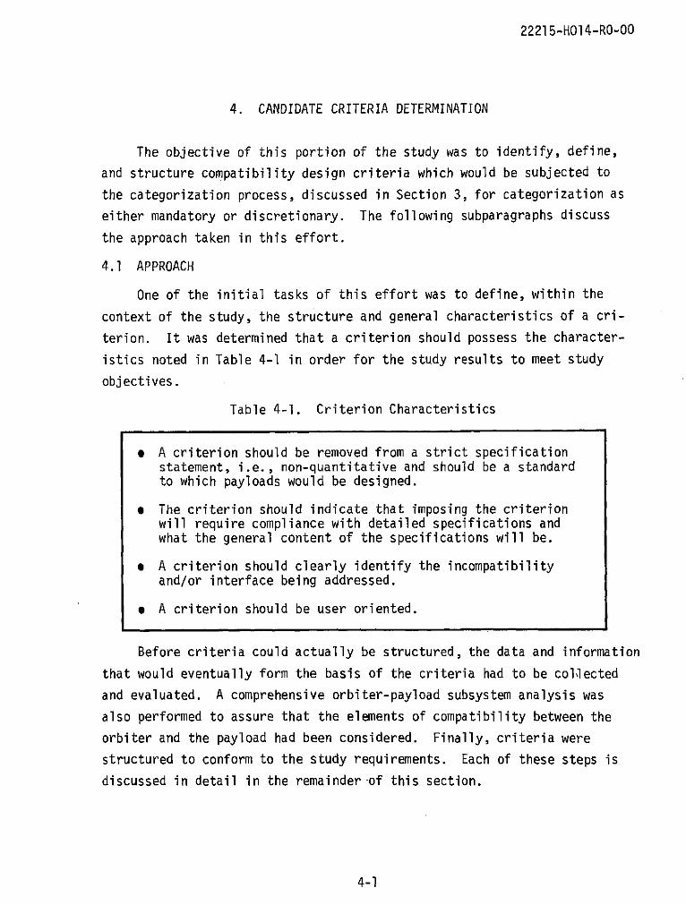
One of the initial tasks of this effort was to define, within the
context of the study, the structure and general characteristics of a cri-
terion. It was determined that a criterion should possess the character-
istics noted in Table 4-1 in order for the study results to meet study
objectives.
Table 4-1. Criterion Characteristics
* A criterion should be removed from a strict specificationstatement, i.e., non-quantitative and should be a standardto which payloads would be designed.
* The criterion should indicate that imposing the criterionwill require compliance with detailed specifications andwhat the general content of the specifications will be.
* A criterion should clearly identify the incompatibilityand/or interface being addressed.
e A criterion should be user oriented.
Before criteria could actually be structured, the data and information
that would eventually form the basis of the criteria had to be collected
and evaluated. A comprehensive orbiter-payload subsystem analysis was
also performed to assure that the elements of compatibility between the
orbiter and the payload had been considered. Finally, criteria were
structured to conform to the study requirements. Each of these steps is
discussed in detail in the remainder of this section.
4-1

22215-H014-RO-00
4.2 DATA COLLECTION AND EVALUATION
The bulk of supporting data and information that subsequently comprised
the criteria was gathered during the Precedent Practices Research portion of
the study. Few systems compatibility criteria were found to exist in the
documentation. The information consisted primarily of specifications, re-
quirements, guidelines, and other specific program information (see Table
2-3) along with relevant, non-program data sources (References 6 and 23).
Of the non-program data sources, the Manned Spacecraft Criteria and
Standards document, MSCM 8080, was particularly relevant because of its
significance as a stand-alone guiding document for present and past manned
spacecraft programs. This information, coupled with the NASA-supplied
shuttle model and appropriate shuttle payload studies documentation
(References 1 and 2), formed the basis for criteria determination.
Approximately 350 data items were accumulated. Within these data
items, much redundancy and overlap existed. However, by researching manyprograms, some assurance that coverage of the interface areas, subsystems,and other compatibility elements between payload and orbiter was realized.
Additionally, an interface design analysis was performed to add to
this assurance as discussed in Subsection 4.3.
4.3 INTERFACE DESIGN ANALYSIS
The orbiter-payload interface consists of the following general con-
siderations defined in Subsection 3.2:
* Orbiter payload-subsystems support
* Orbiter-induced environments or characteristics
* Payload-provided provisions for the interface
* Payload-induced environments or characteristics
* Mission-induced or natural environmental factors
* Payload envelope or mass properties characteristics
In order to develop criteria associated with each of these interface areas,an interface design analysis was performed to determine the design elementswithin each interface area.
4-2

22215-HOI14-RO-00
At present, the family of sortie payloads which will fly on the shuttle
does not exist. Although individual, proposed sortie payloads do exist,
these few payloads do not exhibit the complete set of interface character-
istics that the family of sortie payloads might possess. Therefore, an
analysis was made to determine the typical subsystems, characteristics,
and other considerations conceivable of any given sortie payload. The re-
sults of this analysis, shown in Table 4-2, provided a generalized view of
a sortie payload and formed the baseline for a detailed interface design
analysis. Initial direction for structuring, classifying, and managing
the information that had previously been gathered also resulted from the
generalized sortie payload effort.
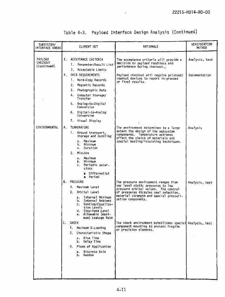
Utilizing the generalized payload analysis, an in-depth analysis was
performed of the subsystem interface parameters and characteristics whichimpact the design and performance of spacecraft payloads. The results of
this analysis, shown in Table 4-3, comprise a complex interrelationship of
design elements and considerations. These elements and considerations,
along with substantiating design rationale and required verification
methods, are shown within each subsystem/interface area.
These two analyses, together with the information obtained from
Precedent Practices Research, provided the supporting data necessary to
structure criteria for each of the sortie payload interface areas exceptfor some specific orbiter-provided and required payload-provided support
provisions and equipment. The NASA-provided shuttle information model
and the Space Shuttle Baseline Accommodations for Payloads document
(Reference 24) were utilized to determine these elements. The orbiter
remote manipulator system (RMS) was examined as part of this effort and
adjudged not to be applicable to this sortie payload criteria study. Also,
the crewmen's pressure garment assemblies, although weight-chargeable to
payloads, are not payload equipment and thus are inappropriate for inter-
face definition within the sortie payload scope of this study.
The results of the interface design analysis accomplished two purposes.
First, it established a basis for payload subsystem and interface area
selection used for classification and control of criteria. Second, the
analysis identified the elements of interface within each subsystem or
interface area that were subsequently used in criteria determination:
These two items are discussed further in the following two subsections.
4-3
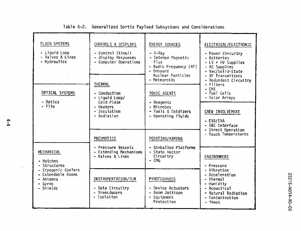
Table 4-2. Generalized Sortie Payload Subsystems and Considerations
FLUID SYSTEMS CONTROLS & DISPLAYS ENERGY SOURCES ELECTRICAL/ELECTRONIC
- Liquid Loop - Control Stimuli - X-Ray - Power Circuitry- Valves & Lines - Display Responses - Intense Magnetic - Batteries- Hydraulics - Computer Operations Flux - LV + HV Supplies
- Radio Frequency (RF) - AC Supplies- Onboard - Vac/Solid-State
Nuclear Particles - RF Transmitters- Meteoroids - Redundant Circuitry
THERMAL - Filters- EMI
OPTICAL SYSTEMS - Conduction TOXIC AGENTS - Fuel Cells- Liquid Loop/ - Solar Arrays
- Optics Cold Plate - Reagents- Film - Heaters - Microbes
- Insulation - Fuels & Oxidizers CREW INVOLVEMENT- Radiation - Operating Fluids
- EVA/IVA- D&C Interface- Direct Operation- Touch Temperatures
PNEUMATICS POINTING/AIMING
- Pressure Vessels - Gimballed PlatformsMECHANICAL - Extending Mechanisms - State Vector
- Valves & Lines Circuitry ENVIRONMENT- Hatches - CMG- Structures - Pressure- Cryogenic Coolers - Vibration- Extendable Booms - Acceleration- Antenna INSTRUMENTATION/TLM PYROTECHNICS - Thermal- Gyros - Humidity- Shields - Data Circuitry - Device Actuators - Acoustical
- Transducers - Boom Jettison - Natural Radiation- Isolation - Equipment - Contamination
Protection - ShockO

22215-HOl4-RO-00
Table 4-3. Payload Interface Design Analysis
SUBSYSTEM/ VERIFICATIONINTERFACE AREAS ELEMENT SET RATIONALE METHOD
COMMUNICATIONS/ A. FREQUENCY ALLOCATIONS The communications subsystem designers Analysis, testDATA 1. Carriers will require these definitions to select
components. Since a manned vehicle will2. Modulation have voice, beacon and telemetry fre-
3. Side Bands quencies, the interference problem mustbe considered in the selection of center
4. Filter/Attenuation frequencies, as well as the side-bandingRequirements effects. A consideration in the defini-
5. Interfering Signal tion of antennas and power levels is the
Level Limits percent of communication coverage de-sired throughout the orbit. Since the
B. ANTENNA REQUIREMENTS ground stations' locations and capabili- Analysis
I. Gain Characteristics ties are known, the orbiter equipment isselected accordingly.
2. Main Lobe Pattern
3. Allowable Side-Lobes
4. Polarization/Phasing
5. Orientation of Axis
a. Fixedb. Drive Patternc. Tolerance of
Alignment
C. TRANSMITTER POWER Test
1. Carrier-to-NoiseRatio
2. Beamwidth
3. Single Carrier Power
4. Multi-carrier PowerDegradation Rate
5. Beacon Modes
6. Amplitudes
a. Peakb. Modulationc. Attenuation re-
quirements
7. Modulation Losses
D. RECEIVER POWER Analysis, test1. Up-link Threshold
2. Noise Figure
3. Sensitivity
4. Center-FrequencyStability
E. ELECTRICAL REQUIREMENTS Electrical requirements must be stipu- Analysis
1. DC Voltages lated to allow power budget to be formu-lated.
2. Power Consumption
a. Turn-onb. Peakc. Average
4-5

2221 5-H014-RO-00
Table 4-3. Payload Interface Design Analysis (Continued)
SUBSYSTEM/ VERIFICATIONINTERFACE AREAS ELEMENT SET RATIONALE METHOD
COMMUNICATIONSi F. DATA HANDLING The data gathering rate and data trans- AnalysisDATA mission rate relate to ground stationContinued) . Data Gathering Rate coverage. If the ground station(s)
2. Data Transmitting Rate accepting data cannot record all of the
3. Data Storage Require- data on a single orbital pass of thements vehicle, data storage capability must
increase to preclude excessive loss of4. Data Conversions data. The format of transmitted data,
a. Analog-to-Digital i.e., bits per word and words per frame,b. Digital-to-Analog establish the required hardware capabi-c. Encoding lity and data rates.
(encrypting)d. Decoding
(decrypting)e. Minimum Conversionf. Format(s)
5. Maximum AllowableData Loss
a. Storage Overflowb. Modulation Lossc. Signal Degradation
e Low power* Interference
CREW A. CONSTRAINT REQUIREMENTS Crew constraints must be provided to Analysis1. Launch Profile allow personnel to move about the vehi-
cle and to operate the experiments in a2. Work-Station/ reduced-gravity environment. Such con-
Walkway Aids straints are for both safety and conve-
3. Extra-Vehicular nience of task performance.
Activities
4. Re-entry & LandingProfile
B. PERSONNEL TASKS The demands upon personnel time must be Task analysis1. Orbiter Functions budgeted to provide a balance of work/
rest without extending the task require-2. Experiment Operation ments of any crew member. The tasks
3. Experiment Deployment must be analyzed against the missiontimeline to eliminate conflicts.
4. EVA
C. PAYLOAD STRUCTURE The payload structure and orbiter-to- Analysis
i. Crew Access Require- payload interface will be designed toments facilitate the required personnel move-
ments and tasks.a. Monitorb. Adjustc. Deploy
2. Intra-VehicularMobility
a. Walk-Way/Crawl-space
b. Safetyc. Strength
4-6

2221 5-HO14-RO-00
Table 4-3. Payload Interface Design Analysis (Continued)
SUBSYSTEM/ VERIFICATIONINTERFACE AREAS ELEMENT SET RATIONALE METHOD
CREW D. PAYLOAD LAYOUT The payload must be arranged to maximize Analysis(Continued) 1. Visibility personnel efficiency at experiment tasks.
2. Display/ReadoutDevices
3. Task Analysis andFacility of Access
E. ENVIRONMENT The primary concern of the vehicle-to- Analysis
1. Vehicle/Payload payload environment design is crewsafety and comfort without undue expendi
a. Pressurized/air- ture of space, weight and funds.locked configura- Lighting must be adequate for flighttions duties such as monitoring displays,
b. Thermal extremes adjusting/calibrating equipment andallowable recording flight/experiment data.
c. Acoustic limitsd. Oxygen systeme. Lighting require-
ments
F. FACILITIES The crew facilities must provide ade- Analysis and
Storage quate storage, comfort, and safety inspection offeatures to support the crew for the drawings
a. Rations duration of the mission.b. Waterc. PGA
2. Comfort
a. Waste disposalb. Rest
ELECTRICAL A. VOLTAGE The electrical subsystem is the primary Test
1. DC system during orbital operations sinceit provides power for communications,
a. Nominal Level(s) experiments and life support system,b. Maximumc. Minimumd. Allowable Ripplee. Regulated Bus
Requirements
B. POWER CAPACITY The electrical system must produce Test
1. Peak Wattage enough power to sustain minimum opera-tions and critical functions. The
2. Normal Usage total mission success will depend a
3. Minimum Requirement great deal upon the adequacy of power.
C. CURRENT Current values are a design guide, Test
i. Peak both for electrical requirements andfor overload protection devices.
a. Cold In-rushb. Hot In-rush
2. Steady-State Average
D. TRANSIENTS Electrical transients should not Test
1. Frequency produce a critical failure in thesystem nor a major degradation of
2. Amplitude mission data.
3. Duration
4-7

22215-HO14-RO-00
Table 4-3. Payload Interface Design Analysis (Continued)
SUBSYSTEM/ VERIFICATIONINTERFACE AREAS ELEMENT SET RATIONALE METHOD
ELECTRICAL E. FREQUENCIES Frequencies should be maintained Test(Continued) 1 Clocking stable to allow other subsystem
. Ccomponents to function regularly.a. Nominalb. Allowable Varia-
tionc. Digital Rates
F. SOURCE The selection of power source should Test
1. Orbiter consider mission length, power require-ments, source weight and the environment
2. Self-Contained Backup/complementary sources should be
3. Test Access evaluated.
G. OVERLOAD PROTECTION Overload at subsystem components should Testnot cause failure of the source, themain bus, nor other subsystems.
H. CABLE DESIGNS, INTERFACE Cables should be designed to distribute Test
1. Connectors the power as required to other subsystemsin a reliable, non-interfering manner.
2. Shielding
a. Protectiveb. EMC
ELECTROMAGNETIC A. SIGNAL INTEGRITY The degree of allowable EMI is stipu- Analysis, test,COMPATIBILITY lated by the signal integrity required drawing inspec-(EMC) I. Data Degradation in the system/subsystem. tion
a. Allowable dBmargin
2. False Clock Signals
3. Frequency Variation
a. Allowable systemrange
b. Ordnance compati-bility range
c. Transient varia-tions, allowablelimits
4. Pulse Shape Variation
B. SOURCE CONTROL Self-generated EMI will be suppressed Analysis, test
1. Internal Self- by design and fabrication; external
generated EMI requires shielding and grounding tech-niques.
2. External SourceSusceptibility
C. GROUNDING REQUIREMENTS Individual subsystems require different Analysis
1. Telemetry grounding designs, dependent upon therespective frequency.
2. Primary Power
3. Heater Circuits
4. Command/ControlCircuits
5. Ordnance Circuits
6. Data Lines
7. RF/CommunicationLines
8. Sensor Circuits
4-8

22215-H014-RO-00
Table 4-3. Payload Interface Design Analysis (Continued)
SUBSYSTEM/ VERIFICATIONINTERFACE AREAS ELEMENT SET RATIONALE METHOD
(EMC) D. PARTS, MATERIALS & The specification of approved parts, Analysis, test(Continued) PROCESS CONTROLS materials and processes will largely
1. RF Bonding dictate the level of EMC achieved atthe system level.
a. Maximum jointimpedance
b. Joint cleanlinessc. Mechanical strap-
ping
2. Signal Separation
a. Cable routingb. Cable configura-
tionc. Shieldingd. Surface coatinge. Groundingf. Filtering
3. Electrochemical Protecting against electrochemical AnalysisCorrosion Control corrosion is a design requirement
a. Isolation or Non- and can be controlled by properUse of Dissimilar materials selection.Metals
* Coating* Bonding
FLUID SYSTEMS A. PRESSURE Fluid systems present a design problem Test
1. Operating Limits where leakage allowances are zero orvery low. Fluid leaks are difficult
2. Maximum Allowable to repair; if the fluid is an oil orSurge fuel leak, the mission can be endan-
3. Maximum Allowable gered by improper design.Leakage
4. Control FunctionLevels
5. Relief Levels
B. CIRCUIT REQUIREMENTS Circuit components are mutual; each Test
1. Reservoir Capacity component size/capacity relates to thesubsystem capacity and operating demands
2. Supply Line Routing/ on the subsystem.Size Limits
3. Return Line Routing/Size Limits
4. Vent and DrainAccommodations
5. Filtration
6. Flow Control Devices
7. Slosh Control
C. ELECTRICAL REQUIREMENTS The fluid system may require electrical Test
a. Primary Power power for pumping or circulating action.b. Heater Power Liquids may require heater protection
against solidifying temperatures or aD. THERMAL INSULATION thermal insulation plan.
REQUIREMENTS
4-9

22215-HO1 4-RO-00
Table 4-3. Payload Interface Design Analysis (Continued)
SUBSYSTEM/ VERIFICATIONINTERFACE AREAS ELEMENT SET RATIONALE METHOD
ALIGNMENT/ A. FIXED ATTITUDE Payload alignment may be critical, Drawing inspec-POINTING 1. Reference Location since it orients the experiments to tion and test
and Axes their design plane and to the variousmission profile forces.
2. Allowable ErrorLimit
B. CONTROLLED ATTITUDE Some payload components may require a Teststabilized or driven attitude to main-
1. Primary Reference tain vertical, target reference or a2. Backup/Secondary skewed-axis orientation. Such require-
Reference ments increase design complexity of
3. Axial Excursion structures/components and influence
Limits experiment layout and power requirements
4. Precession or DriveRate Requirements
5. Damping Ratio
6. Correction Rate
7. Nominal Attitude
C. POINTING COORDINATES Some payload experiments will require Test
I. Reference aiming/tracking on a reference to pro-duce proper results. These require-
2. Elevation Limits ments will specify some structure design!3. Azimuth Limits for access or vision fields and will
necessitate close control of either the4. Pointing Error Limits reference or the pointing device.
5. Scheduled TargetChanges
6. Frequency ofPointing Change
7. Drive Rates Requiredto Maintain Point
PAYLOAD A. CHECKOUT MODES The checkout of the payload will occur TestCHECKOUT 1 Pre-Launch in phases throughout the system schedule.
Flight conditions can be simulated for2. Ascent checkout of the payload prior to launch.
3. Orbital
4. Re-Entry
5. Descent
B. FREQUENCY The frequency and sequence of checkout Analysis
I. One-Time Check are specified to allow an accuratecheckout procedure to be written.
2. Cyclic/Periodic
3. Event-Related
C. SEQUENCE OF ACTIONS Analysis, test.
D. SPECIAL INTERFACES Special interfaces will require special Inspection, test
1. Test Cables, test equipment and possibly structural
Umbilicals, In-flight designs to permit access.
Jumpers'
2. Instrumentation
3. Calibrate/SimulateFixtures
4-10
2221 5-H14-RO-00
Table 4-3. Payload Interface Design Analysis (Continued)
SUBSYSTEM/ VERIFICATIONINTERFACE AREAS ELEMENT SET RATIONALE METHOD
PAYLOAD E. ACCEPTANCE CRITERIA The acceptance criteria will provide a Analysis, testCHECKOUT 1. Parameter/Result List decision on payload readiness and(Continued) 2performance during checkout.,
2. Acceptable Limits
F. DATA REQUIREMENTS Payload checkout will require printout/ Documentation
1. Hard-Copy Records readout devices to report in-processor final results.
2. Magnetic Records
3. Photographic Data
4. Computer Storage/Transfer
5. Analog-to-DigitalConversion
6. Digital-to-AnalogConversion
7. Visual Display
ENVIRONMENTAL A. TEMPERATURE The environment determines to a large Analysis
1. Ground transport, extent the design of the subsystemstorage and handling components. Temperature extremes
affect the choice of materials anda. Maximum special heating/insulating techniques.b. Minimumc. Duration
2. Mission
a. Maximumb. Minimumc. Periodic excur-
sions
* Differential* Period
B. PRESSURE The pressure environment ranges from Analysis, test
1. Maximum Level sea level static pressures to lowpressure orbital values. The control
2. Orbital Level of pressures dictates seal selection,
a. Internal Minimum material strength and special pressuri-
b. Internal Ambient zation components.
c. Venting/Equaliza-tion Levels
d. Stop-Vent Levele. Allowable (maxi-
mum) Leakage Rate
C. SHOCK The shock environment establishes special Analysis, test
1. Maximum G-Loading component mounting to protect fragileor precision elements.
2. Characteristic Shape
a. Rise Timeb. Delay Time
3. Plane of Application
a. Discrete Axisb. Random
4-11

2221 5-HOI4-RO-00
Table 4-3. Payload Interface Design Analysis (Continued)
SUBSYSTEM/ VERIFICATIONINTERFACE AREAS ELEMENT SET RATIONALE METHOD
ENVIRONMENTAL D. VIBRATION Vibrations can destroy the accuracy Analysis, test(Continued) . Frequency Range and even abort the mission if not
considered fully during design phases.2. Amplitude(s)
3. Duration
4. Octave Rate(s)
5. Plane of Application
a. Discrete Axisb. Multi-Axisc. Random
E. RADIATION Radiation levels from all sources have Analysis, testi. Permissible Ambient to be considered since radiation has aLevel cumulative effect upon personnel.
2. Sources
a. On-Board Equipmentb. External Impinge-
ment
e Nominal Rate* Maximum Rates Duration
F. FOREIGN OBJECTS, The incidence of foreign objects such AnalysisIMPACTING as dropped tools, launch-thrown debris
1. Source and meteorites should not endanger themission.
2. Size
3. Velocity
4. Occurrence Internal
G. FOREIGN SUBSTANCE, Contamination of experiment samples, Analysis, testCONTAMINATING payload equipment and crew support1. Material devices dan reduce mission success
and should be considered during2. Density/Size the design phase.
3. Source
4. Longevity/Duration
5. Residue
6. Humidity Limits
7. Salt Spray Limits
8. Dust Limits
9. Outgassing fromInternal Components,Limit
H. ACOUSTIC Noise levels are controlled to reduce Test
1. Maximum Ambient Noise crew fatigue and preclude hearingLevel impairment.
* Octave Band Portiona Center Frequency
Versus Noise Spectra
2. Maximum Peak Level
a. Flight Buffetingb. Ordnance Activitiesc. Equipment Operating
Modes
4-12
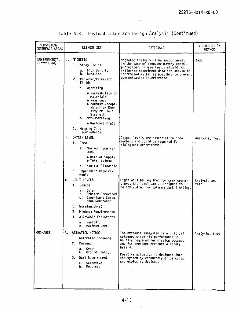
22215-HO14-RO-00
Table 4-3. Payload Interface Design Analysis (Continued)
SUBSYSTEM/ VERIFICATIONINTERFACE AREAS ELEMENT SET RATIONALE METHOD
ENVIRONMENTAL J. MAGNETIC Magnetic fields will be encountered; Test(Continued) 1. Stray Fields in the case of computer memory cores,
propagated. These fields should nota. Flux Density influence experiment data and should beb. Duration controlled as far as possible to prevent
2. Periodic/Permanent communication interference.
Fields
a. Operating
* Permeability ofMaterials
* Remanence* Maximum Accept-
able Flux Den-sity or FieldStrength
b. Non-Operating
a Residual Field
3. Mapping TestRequirements
K. OXYGEN LEVEL Oxygen levels are essential to crew Analysis, testI. Crew members and could be required for
biological experiments.a. Minimum Require-
ment
e Rate of Supply* Total Volume
b. Maximum Allowable
2. Experiment Require-ments
L. LIGHT LEVELS Light will be required for crew opera- Analysis and1. Source tions; the level can be designed to test
be controlled for optimum task lighting.a. Solarb. Orbiter-Generatedc. Experiment Compo-
nent-Generated
2. Wavelength(s)
3. Minimum Requirements
4. Allowable Variations
a. Periodicb. Maximum Level
ORDNANCE A. ACTUATION METHOD The ordnance subsystem is a critical Analysis, test1. Automatic Sequence category since its performance is
usually required for mission success2. Command and its presence presents a safety
a. Crew hazard.
b. Ground Station Positive actuation is designed into3. Dual Requirement the system by redundancy of circuits
a. Selective and explosive devices.
b. Required
4-13

2221 5-HO4-RO-00
Table 4-3. Payload Interface Design Analysis (Concluded)
SUBSYSTEM/ VERIFICATIONINTERFACE AREAS ELEMENT SET RATIONALE METHOD
ORDNANCE B. ACTUATION SEQUENCE Analysis and(Continued) 1. Safing/Arming test
2. All-Fire
3. Discrete Fire
4. Fire IntervalsSchedule
C. VOLTAGE REQUIREMENTS Sample test1. Minimum Firing Level
2. Sustained VoltageLevel
3. Minimum Rise Timeat Initiation
STRUCTURAL/ A. ENVELOPE SIZE, LIMITS The structure and mechanical subsystem Drawing inspec-MECHANICAL B. INSTALLATION supports the total mission. System tion, part
elements are maintained in specified inspection,1. Method relationships to each other by the assembly test2. Interface Requirements structure; the crew safety depends on
the structure; and flight attitudes are3. Attitude/Position influenced by the structure moments and
center-of-gravity.
C. MASS PROPERTIES/WEIGHT TestORIENTATION DYNAMICS
D. CENTER-OF-GRAVITY TestREQUIREMENTS
E. ACCESS REQUIREMENTS Drawing inspec-1. Ground Operations tion, test
2. Flight Operations
F. MAINTAINED ATTITUDE OR TestORTHOGONALITY REQUIREMENTS
G. DEPLOYMENT REQUIREMENTS Requirements for extending or ejecting Test1. Excursion Axis/Plans experiments increases the structural/
mechanical design complexity. The2. Travel Limit(s) stipulated limits of such deployments3. Frequency of Deploy- allow the design to be adequately
ment and Schedule prepared.
4. Rate of Deployment/Retraction
H. MATERIALS Material selection should exclude Analysis, test1. Non-allowable incompatible materials, separate or
Structures/Materials eliminate dissimilar metals withgalvanic potentials, control the use
2. Requirements and of coatings and bondings, and assureAllowances adequate strength for all environmental
a. Coatings requirements.
b. Bondings andAdhesives
c. Paints
3. Strength
J. MARKINGS AND InspectionIDENTIFICATIONS
K. RESONANCE Structures and mechanisms should not Testi. Natural Frequencies demonstrate natural frequencies and
resonances in the range of operating2. Transmissibility vibration frequencies.
4-14
22215-HOl4-RO-00
4.4 SUBSYSTEM DETERMINATION
The subsystems and considerations of the interface design analyses
were necessarily general because sortie payloads have not yet been fully
specified. In order to more closely correspond to the orbiter subsystem
and interface area nomenclature, the following categories for payload
criteria management and control were selected:
* Communications * Guidance, Navigation* Cryogenics and Controle Data Processing * Instrumentation
and Software * Onboard Checkout* Displays and Controls * Payload Environment* Electrical Power * Pyrotechnics* Environmental Control e Structures
and Life Support * Thermal Control* Extravehicular/Intra- * General
vehicular Activity
This selection should aid in understanding the criteria categories andtherefore assist in the usability of the criteria.
4.5 CRITERIA SYNTHESIS
The preponderance of information gathered to support the criteriadetermination task were not criteria. The data consisted primarily ofspecification statements, guidelines, and other requirements. This in-formation was sorted into appropriate subsystem categories and the redun-dant and overlapping information was deleted (which reduced the volume ofinformation considerably). At this point, those data which were obviouslynot applicable to the compatibility study were also omitted. For instance,information which involved ground support equipment, safety, procedures,or non-sortie elements was rejected or referred to the Crew Safety CriteriaStudy (Volume II). In effect, the first three blocks of the design cate-gorization process were implemented to a certain degree. Those items de-leted during this effort, as well as all other rejected information, wereretained for NASA use.
4-15

22215-HOl4-RO-00
The iterative process of criteria determination continued by com-
bining data elements where appropriate, and structuring the information
into proper syntax for criteria presentation. Concurrent with the latter
stages of the synthesizing effort, candidate criteria were subjected to
the categorization process. This accomplished two purposes. It enabled
the criteria syntax and categorization processes to be adjusted for clarity
and completeness. It also enabled cross-correlation between the processes
and criteria to assure that the basic interfaces for systems compatibility
were being addressed.
The synthesizing task reduced the original data from Precedent
Practices Research and the interface design analyses to approximately 50
criteria. These criteria were then subjected to the categorization pro-
cesses (Section 3) for further analysis and categorization as mandatory
or discretionary criteria.
4-16

22215-H014-RO-O0
5. SYSTEMS COMPATIBILITY DESIGN AND VERIFICATION CRITERIA
The principal results of this study are presented in this section.
They are the recommended minimum set of criteria considered mandatory, at
any cost, to achieve orbiter-payload systems compatibility. A partial
listing of the unbounded set of discretionary criteria (see Table 1-2) are
also presented. As required, rationale for each criteria categorization
is included along with the recommended minimum verification level for
mandatory criteria.
The total of 34 mandatory and 7 discretionary criteria are distributed
within the 15 subsystem/interface areas as shown below. The criteria are
Table 5-1 Table 5-2Subsystem/Interface Area Mandatory Discretionary
9 Communications 4 --
* Cryogenics 1 --
* Data Processing and Software 1 --
* Displays and Controls 1 --
* Electrical Power 4 --
* Environmental Control and 1 --Life Support
* Extravehicular/Intravehicular 1 --Activity
* Guidance, Navigation and 2 --Control
* Instrumentation 1 5
* Onboard Checkout 1 1
* Payload Environment 1 --
* Pyrotechnics 1 --
* Structures 9 1
* Thermal Control 2 --
* General 4 --
5-1

22215-HO14-RO-00
presented in summary in Table 5-1 and in their entirety in Tables 5-2 and
5-3. Specific MSCM 8080 (Reference 23) standards which contributed to
criteria development are referenced. Also, to denote whether orbiter or
payload operation is of primary concern, the word "orbiter" or "payload"
is underlined in the rationale of each criterion. Criteria which address
only payload operation are further identified with the note "This criterion
may be controlled by payload management". This indicates that even though
mandatory criteria are levied by shuttle management to provide for nominal
operation, actual control and management of the criteria after being levied
may be exercised by payload management. The criteria and rationale pre-
sented are the result of the criteria structuring effort described in
Section 4 and the subsequent subjection of these criteria to the design and
verification processes discussed in Section 3.
5-2

22215-HO14-RO-00
Table 5-1. Systems Compatibility Design Criteria Summary
COMMUNICATIONS (4) ECLS (1) PYROTECHNICS (1)
* Commands IM,-- * Atmospheric Maintenance IM,-- a Generated Environment IM,--
-Uplink -Contamination
-PCDS EVA/IVA (1) -Shock
-Onboard -Thrust
# TV Payloads IM,-- * Astronaut Capabilities IM,--
-Hardware -Reach-Signal Characteristics -Visibility
* Voice IM,-- -Torque/Force STRUCTURES (10)
* Carrier Frequencies lM,-- -Transferables
e Mounting Provisions IM,--GN&C (2) -Location, Attachment
CRYOGENICS (1) a Orientation & A!gnment 1M,--a Realtime Data IM,-- * Orbiter-InducEl Environ.IM,--
* Reactants IM,-- -Data Characteristics -Acceleration
-Purity 9 Pointing/Stabilizing 1M,-- -Shock
-Cleanliness -Accuracy -Vibration-Stability -Acoustical-Deadband -Thermal
-Nuclear Radiation
DATA PROCESSING & SOFTWARE (1) INSTRUMENTATION (6) -Magnetic Fields
-Contamination
s Computation Support IM,-- e Downlink IM,-- -Structural Distortion
-RAU e P/L Envelope & Mass
-Hardware Properties IM,--
-Signal Characteristics e Boom-Mounted Equipment lM,--DISPLAY & CONTROL (1) e Transducers --,lD * Fields-of-View IM,--
-Operating Range e Materials IM,--
* Panels IM,-- -Resolution e Flaking 1M,--
-Hardware * Telemetry --,4D e Service Panels 1M,--
-Electrical Characteristics a Decompression --,1D
ONBOARD CHECKOUT (2)
ELECTRICAL POWER (4) * Go/No-Go Criteria 1M,--
-Checkout Command Decoder THERMAL CONTROL (2)* Power Sources IM,-- -Stored Program Processor
-Hardware e Payload Viewing --,1D e Heat Transport IM,---Voltage-Transi ents -Coldplate Hardware
-Impedance P/L ENVIRONMENT (1) Temperature Limits lM,--
-Grounding
* EMC and RF iM,-- 9 Natural Environment lM,--
-Conducted -Low-g & Pressure-Radiated -Space Radiation GENERAL (4)
* P/L-InducedCharacteristics lM,-- -Space Thermal
-Load Impedance -Meteoroid * Orbiter Support Limits IM,--
-Transients -Space Magnetic Fields * P/L-Induced Forces,Impulses IM,--
-Capacitance -Humidity P/L Inducede P/L Induced
-Feedback -Solar Illumination Environments lM,--a Corona lM,-- -Contaminations a Waste Storage ,M,--
M = Mandatory D = Discretionary
5-3

22215-H014-RO-00
Table 5-2. Mandatory Compatibility Design Criteria
DESIGN CRITERION CATEGORIZING RATIONALE VERIFICATION
COMMUNICATIONS
COMM-I. Payloads that require This design criterion is applicable to sortie pay- Testground and/or orbiter commands loads that require orbiter support for payloadmust be designed to interface commanding. Crew hazards are not a considerationwith the GFE Payload Command of this criterion nor is a contingency situationDecoder Subunit (PCDS). The involved. Adhering to this criterion assuresstandard PCDS interface require- that the payload can be commanded in a nominalments are: interconnecting manner and is therefore mandatory.hardware and locations; cabletype and size; command signallevels, both on and off states;number and type of commandsrequired; and impedancematching.
COMM-2. Payloads requiring This design criterion for sortie payloads which Testorbiter support for display produce TV signals is applicable to those payloadsand/or downlink transmission of that require orbital support to transmit thoseTV signals must interface with signals to ground or to the orbiter displays.specified orbiter design con- This criterion would be a normal requirementfiguration. This interface must for payloads which require this support andbe compatible with the inter- is not imposed to circumvent a contingency orconnecting hardware and the abnormal situation. If the payload designfollowing electrical signal for this interface is improper, payloadcharacteristic/requirements: operation would be non-nominal; therefore,data formats, bit rates, opera- the criterion is mandatory.tional modes, coding accuracy,input/output load impedance,duty cycle, and the active andquiescent operating voltages.
COMM-3. Sortie payload elements, This orbiter payload-support element is provided Testrequiring two-way voice communi- for those payloads which require voice communica-cations with the orbiter crew tions. Sortie payload design is affected by thisand/or ground, must be designed support element in that hardware connection, cableto interface with the orbiter size, length, and type along with signal charac-Mission Specialist Station teristics must interface properly with the stand-through the standardized audio ardized orbiter equipment in order to receive andstations located in the payload transmit voice communications. Voice supportbay with respect to inter- would be used in the normal operation of the pay-connecting hardware, impedance load and it is mandatory that payloads adhere tomatching, and driver voltage. this criterion.
COMM-4. Payload-transmitted Carrier frequencies of payloads and the orbiter Inspection/carrier frequencies must be that are too close could cause interference to Testutilized that allow sufficient occur in orbiter-to-ground voice and data trans-bandwidth separation between mission or in payload communications trans-payload and orbiter carrier missions. This interference could prevent nominalfrequencies to preclude inter- operations of either the orbiter or the payloadference. Orbiter carrier fre- and it is therefore mandatory that payloads bequencies and permissible pay- designed to adhere to this criterion.load carrier frequencies willbe specified to assure properallocation.
*This criterion may be controlled by payload management.
5-4

22215-HO14-RO-00
Table 5-2. Mandatory Compatibility Design Criteria (Continued)
DESIGN CRITERION CATEGORIZING RATIONALE VERIFICATION
CRYOGENICS
CRYO-1. Payload elements which Payloads, like sortie laboratories, may utilize Inspectionutilize cryogenic reactants fuel cells to provide power. These power sourcessupplied by the orbiter must be utilize cryogenic reactants and can be simultan-designed to interface with the eously loaded from common shuttle/payload umbili-interconnecting hardware and cals. The payload must be designed to assure thatmust be able to operate at speci- the reactant plumbing interfaces properly with thefied reactant purity and systems orbiter plumbing so that the payload reactantcleanliness levels. (See MSCM storage tanks can be loaded. If the payload fuel8080, No. 78.) cells utilize orbiter reactants, the plumbing hard-
ware must also be proper to assure that reactantsare supplied to the payload fuel cells. Payloadsystems cleanliness requirements must meet andreactant purity requirements must not exceedthe orbiter specifications. The considerationsof this criterion, therefore, impact nominaloperation and are mandatory for payloads thatemploy fuel cells.
DATA PROCESSING AND SOFTWARE
DP&S-1. Payloads requiring the Payloads may utilize the orbiter computer for real- Testorbiter payload and performance time data computation and manipulation for datamonitoring computers for compu- display and other purposes. In order to utilizetation support must be designed the orbiter computer support, the payload willto interface with the orbiter have to properly interface with the orbiter com-data processing and software puter system through input/output units. Thesubsystem through the input/ payload must be designed to orbiter standards foroutput units with respect to all each of the specifications or nominal payloadhardware and software specifi- operation will not be possible. Therefore, thecations. criterion is mandatory.
DISPLAYS AND CONTROLS
D&C-1. Instrumentation and con- Sortie payload design must be compatible with Testtrol panels provided by the pay- orbiter space allocation and electrical char-load for location in the Mission acteristics in order for the payload hardware toSpecialist Station, Commander/ fit and operate properly with the orbiter. Incom-Pilot, or Payload Specialists patibility at this interface could prevent pay-Stations that require orbiter load information from being received and/or thesupport for power or data dis- payload from being controlled. Since nominal pay-tribution must be designed to load operation would be impaired if this interfaceinterface with orbiter configu- was improper, the criterion is mandatory.ration and must be compatiblewith the orbiter space allocated.The orbiter power configurationwill specify the maximum power,voltage levels, ripple and tran-sients, source impedance, andreturn grounding requirements.The data distribution configura-tion will specify the cable sizeand type, signal levels, dutycycle, number of functions, andimpedance matching requirements.
*This criterion may be controlled by payload management.
5-5
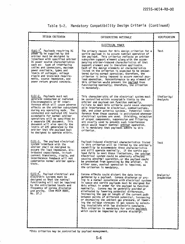
22215-HO14-RO-00
Table 5-2. Mandatory Compatibility Design Criteria (Continued)
DESIGN CRITERION CATEGORIZING RATIONALE VERIFICATION
ELECTRICAL POWER
ELEC-1. Payloads requiring DC The primary reason for this design criterion for a Testpower to be supplied by the sortie payload is to assure nominal operation oforbiter must be designed to the payload. This criterion reflects an orbiterinterface with specified orbiter subsystem support element along with the accom-DC power source characteristics panying orbiter-induced characteristics of thatsuch as: type of interfacing support element and is therefore applicable.cables and connectors, maximum Each of the design elements or characteristicspower available, types and listed in the criterion is expected to be encoun-levels of voltages, voltage tered during normal operation; therefore, theripple and transient require- criterion is being imposed to assure nominal pay-ments, source impedance, and load operation. Nonconformance to any element ofpower return ground concepts, this criterion would prevent the payload from
functioning nominally; therefore, the criterionis mandatory.
ELEC-2. Payloads must not This characteristic of the electrical system must Similarity/generate conducted or radiated be controlled within acceptable limits so the Analysiselectromagnetic or RF inter- orbiter and payload can function nominally.ference which will cause adverse Failure to meet this criteria could cause unaccept-effects on the orbiter subsystems able interference in electrical, communications,during any operating mode. The G&N, and other avionics systems. Potential inter-conducted and radiated EMI levels ference from these sources is anticipated wheneveracceptable for normal orbiter electrical systems are used. Shielding, selectionoperations will be specified in of proper components, suppression and filteringa separate EMC document. This are usually used to prevent such interferencedocument will also specify the which would impair nominal orbiter operation.levels of EMI generated by the It is mandatory that payloads adhere to thisorbiter that the payload must criterion.be designed to operate within.
ELEC-3. The payload electrical Payload-induced electrical characteristics listed Testsystem interface with the in this criterion will be limited by the orbiter'sorbiter shall be designed to capability to accommodate these characteristicsassure the load impedance, dis- and still operate nominally. If the sortie pay-tributed capacitance, in-rush load fails to meet these limitations, the orbitercurrent transients, ripple, and electrical system could be adversely affectedinterference feedback will not causing abnormal operation, or the payload couldcompromise normal orbiter opera- be prevented from operating by the orbiter. Intions. either case, nominal operation is impaired; so
the criterion is mandatory.
ELEC-4. Payload electrical and Corona effects could distort the data being Analysis/electronic systems must be gathered by a payload. Corona discharge or arc- Inspectiondesigned so that the nominal ing is a normal occurrence with electrical systemsfunctioning will not be impaired in space and sortie payloads must be designed forby the anticipated levels and this effect in order for the payload to functionfrequency of corona discharge nominally. Corona may be generally avoided orand arcing. (See MSCM 8080, eliminated by lowering potential differences,No. 37.) increasing the gap or length of the current path
between points of different potential, increasingor decreasing the ambient gas pressure, or lower-ing the voltage stresses in gas spaces by select-ing insulations with low dielectric constants.This criterion is mandatory for sortie payloadswhich could be impacted by corona discharge.
*This criterion may be controlled by payload management.
5-6

22215-HO14-RO-00
Table 5-2. Mandatory Compatibility Design Criteria (Continued)
DESIGN CRITERION CATEGORIZING RATIONALE VERIFICATION
ENVIRONMENTAL CONTROL ANDLIFE SUPPORT
ECLS-1. Manned payload elements Failure to meet this design criterion would cause Analysis/Testinterfacing with orbiter atmos- excessive utilization of the orbiter supportpheric capabilities must be provisions which could lead to crew discomfort anddesigned to insure the following possibly to non-nominal operations. Therefore,environmental requirements are to assure nominal orbiter mission operations, thecompatible with the orbiter criterion is considered mandatory.system: pressure, temperature,humidity, CO2 control, and leakrate.
EXTRAVEHICULAR/INTRAVEHICULARACTIVITY
EVA-I. Payloads requiring EVA/ In order for the sortie payload to receive crew DemonstrationIVA support to complete their support, it must be designed so the crew inter-missions must be designed to con- face systems can be operable in the space en-form to the applicable man- vironment. This criterion reflects a nominalmachine interface standards with situation when crew support is required forrespect to crew capabilities such necessary payload operation. To provide foras reach, visibility, maximum nominal payload and crew operation, thistorque and force limitations, and criterion is categorized as mandatory.ability to handle the size andweight of transferable payloads.
GUIDANCE, NAVIGATION ANDCONTROL
GN&C-1. Payloads requiring orbi- Sortie payloads will utilize GN&C data for real- Analysis/Testter guidance and navigation real- time purposes such as for pointing accuracy deter-time data must be designed to mination and data correlation. This criterion
-interface with the orbiter GN&C will affect how the payload is designed in ordercomputer. This interface to utilize the orbiter support element properly..requires that the payload be Nominal payload operation or data correlationcapable of connecting to the would be affected if this payload interface werehardware provided by the orbiter not designed properly. Therefore, the criterionand accepting the data format is mandatory.(timing, state vector initiali-zation and extrapolation, andspacecraft attitudes and atti-tude rates) along with thecharacteristics of the dataprovided.
GN&C-2. Payloads which must be If a sortie payload must be pointed toward some Analysispointed/stabilized for data area of interest for data gathering purposes ingathering or other purposes must order for the payload to accomplish its purpose,be designed to operate and inter- this criterion must be considered in payloadface with the orbiter consider- design. A definite interface exists since theing the orbiter capabilities for orbiter is providing a support element (point-pointing accuracy, stability ing) with certain limitations which the payloadrate, and deadband. must consider in its design. Payloads may
incorporate additional gimballing systems toeffect greater fccuracy than the orbiter aloneprovides. Nonetheless, these systems also mustinterface satisfactorily with the orbiter capa-bilities for pointing. The limitations onaccuracy, etc., are expected and are specifiedto allow design for nominal payload operation;therefore, the criterion is mandatory.
*This criterion may be controlled by payload management.
5-7

22215-HO14-RO-00
Table 5-2. Mandatory Compatibility Design Criteria (Continued)
DESIGN CRITERION CATEGORIZING RATIONALE VERIFICATION
INSTRUMENTATION
INST-1. Payloads that generate In order for sortie paylods to transmit data to Testdata to be downlinked must inter- earth through the orbiter in a nominal manner, theface with the orbiter Stored design of interfacing instrumentation must beProgram Processor through the proper. This orbiter support element is providedGFE Regional Acquisition Unit for normal payload data transmission and therefore(RAU). Payloads that generate primarily affects payload operation. Improperwideband data to be downlinked design at this interface could prevent payloadmust interface with the orbiter data transmission and therefore render the payloadFM transmitter. These inter- useless. Therefore, the criterion is mandatory.faces require that the hardwareand data signal characteristicsof the payload instrumentationconform to the specificationsof the orbiter equipment.
ONBOARD CHECKOUT
OBCO-1. Payloads that require Prior to liftoff, the payload can be checked out Testinflight checkout must be via the Checkout Command Decoder for serial digi-designed to interface with the tal checkout commands and data and via the Storedstandardized Checkout Command Program Processor for payload narrowband checkoutDecoder and the Stored Program data. The Decoder and Processor are connected toProcessor with respect to hard- the ground by hardwire. The sortie payloads mustware connection, checkout com- interface with these checkout units in order tomands and data characteristics determine if the payload is capable of flightand formats. operation. This criterion reflects an orbiter
support element used to determine if the a loadis capable of nominal operation and is manFatory.
PAYLOAD ENVIRONMENT
PLE-l. Payloads must be The primary reason for this sortie payload design Similarity/designed to operate nominally criterion is to assure nominal operation while Analysisunder the influence of expected under the influence of mission-induced naturallevels of these environmental ele- environments. Since certain levels of each ofments: low gravity and pressure, these elements is expected during a mission, pay-space radiation, space thermal load design must include utilization of shielding,characteristics, meteoroid insulation, and other protective devices to allowimpact, space magnetic fields, nominal operation. If the payload did not meetsolar illumination, and atmos- this criterion, nominal operation would be jeop-pheric contaminations such as ardized and thus the criterion is consideredhumidity, dust, fungus, and mandatory.ozone.
*This criterion may be controlled by payload management.
5-8
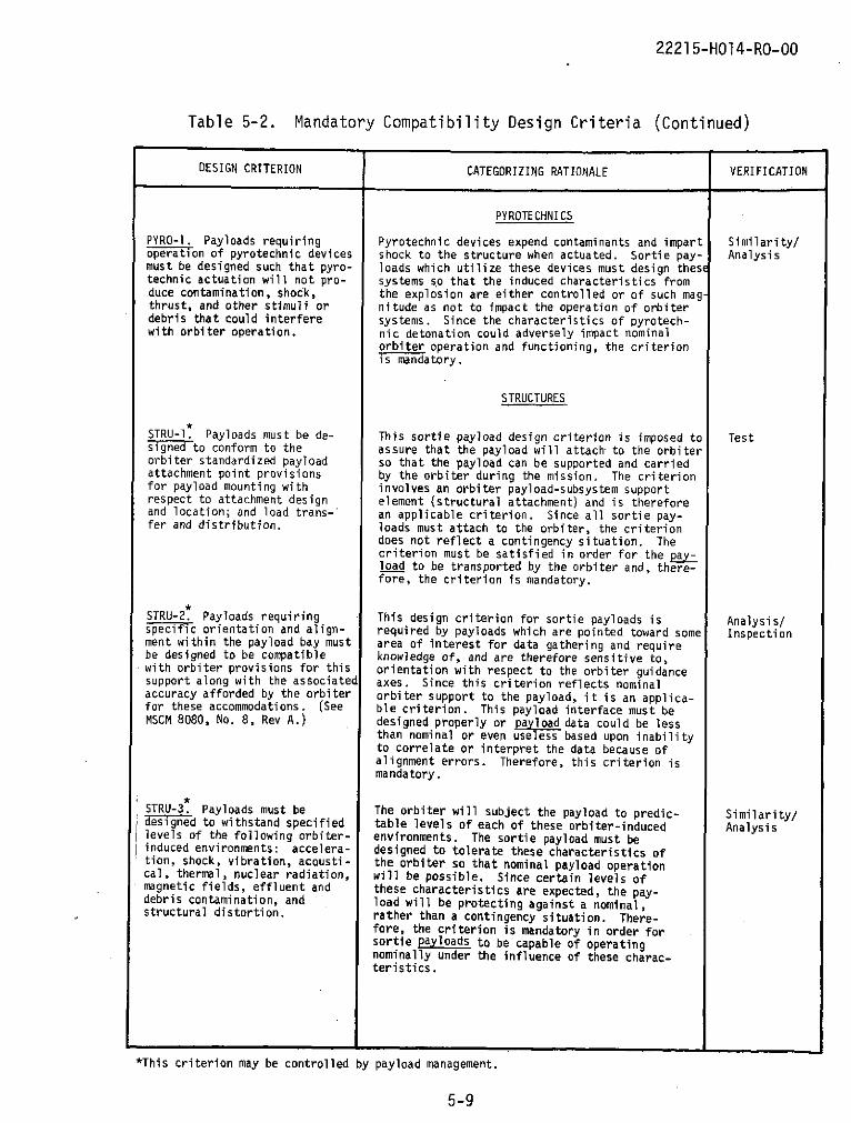
22215-H014-RO-00
Table 5-2. Mandatory Compatibility Design Criteria (Continued)
DESIGN CRITERION CATEGORIZING RATIONALE VERIFICATION
PYROTECHNICS
PYRO-1. Payloads requiring Pyrotechnic devices expend contaminants and impart Similarity/operation of pyrotechnic devices shock to the structure when actuated. Sortie pay- Analysismust be designed such that pyro- loads which utilize these devices must design thesetechnic actuation will not pro- systems so that the induced characteristics fromduce contamination, shock, the explosion are either controlled or of such mag-thrust, and other stimuli or nitude as not to impact the operation of orbiterdebris that could interfere systems. Since the characteristics of pyrotech-with orbiter operation. nic detonation could adversely impact nominal
orbiter operation and functioning, the criterionis mandatory.
STRUCTURES
STRU-1. Payloads must be de- This sortie payload design criterion is imposed to Testsignedto conform to the assure that the payload will attach to the orbiterorbiter standardized payload so that the payload can be supported and carriedattachment point provisions by the orbiter during the mission. The criterionfor payload mounting with involves an orbiter payload-subsystem supportrespect to attachment design element (structural attachment) and is thereforeand location; and load trans- an applicable criterion. Since all sortie pay-fer and distribution. loads must attach to the orbiter, the criterion
does not reflect a contingency situation. Thecriterion must be satisfied in order for the pay-load to be transported by the orbiter and, there-fore, the criterion is mandatory.
STRU-2. Payloads requiring This design criterion for sortie payloads is Analysis/specific orientation and align- required by payloads which are pointed toward some Inspectionment within the payload bay must area of interest for data gathering and requirebe designed to be compatible knowledge of, and are therefore sensitive to,with orbiter provisions for this orientation with respect to the orbiter guidancesupport along with the associated axes. Since this criterion reflects nominalaccuracy afforded by the orbiter orbiter support to the payload, it is an applica-for these accommodations. (See ble criterion. This payload interface must beMSCM 8080, No. 8, Rev A.) designed properly or payload data could be less
than nominal or even useless based upon inabilityto correlate or interpret the data because ofalignment errors. Therefore, this criterion ismandatory.
STRU-3. Payloads must be The orbiter will subject the payload to predic- Similarity/designed to withstand specified table levels of each of these orbiter-induced Analysislevels of the following orbiter- environments. The sortie payload must beinduced environments: accelera- designed to tolerate these characteristics oftion, shock, vibration, acousti- the orbiter so that nominal payload operationcal, thermal, nuclear radiation, will be possible. Since certain levels ofmagnetic fields, effluent and these characteristics are expected, the pay-debris contamination, and load will be protecting against a nominal,structural distortion. rather than a contingency situation. There-
fore, the criterion is mandatory in order forsortie payloads to be capable of operatingnominally under the influence of these charac-teristics.
*This criterion may be controlled by payload management.
5-9
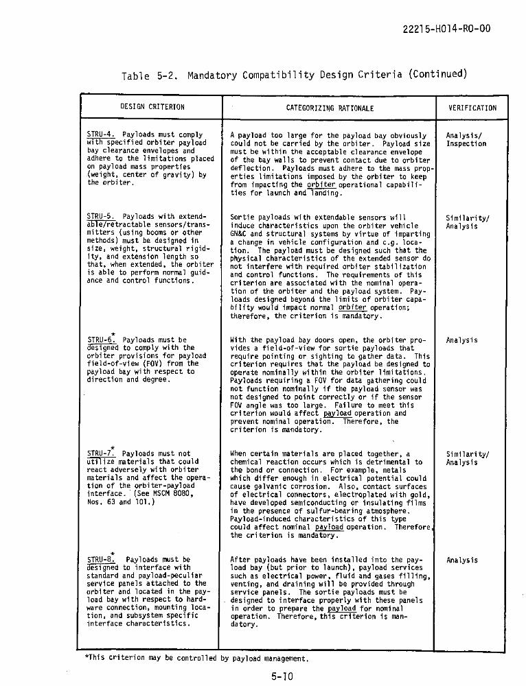
22215-H014-RO-00
Table 5-2. Mandatory Compatibility Design Criteria (Continued)
DESIGN CRITERION CATEGORIZING RATIONALE VERIFICATION
STRU-4. Payloads must comply A payload too large for the payload bay obviously Analysis/with specified orbiter payload could not be carried by the orbiter. Payload size Inspectionbay clearance envelopes and must be within the acceptable clearance envelopeadhere to the limitations placed of the bay walls to prevent contact due to orbiteron payload mass properties deflection. Payloads must adhere to the mass prop-(weight, center of gravity) by erties limitations imposed by the orbiter to keepthe orbiter, from impacting the orbiter operational capabili-
ties for launch and landing.
STRU-5. Payloads with extend- Sortie payloads with extendable sensors will Similarity/able/retractable sensors/trans- induce characteristics upon the orbiter vehicle Analysismitters (using booms or other GN&C and structural systems by virtue of impartingmethods) must be designed in a change in vehicle configuration and c.g. loca-size, weight, structural rigid- tion. The payload must be designed such that theity, and extension length so physical characteristics of the extended sensor dothat, when extended, the orbiter not interfere with required orbiter stabilizationis able to perform normal guid- and control functions. The requirements of thisance and control functions, criterion are associated with the nominal opera-
tion of the orbiter and the payload system. Pay-loads designed beyond the limits of orbiter capa-bility would impact normal orbiter operation;therefore, the criterion is mandatory.
STRU-6. Payloads must be With the payload bay doors open, the orbiter pro- Analysisdesigned to comply with the vides a field-of-view for sortie payloads thatorbiter provisions for payload require pointing or sighting to gather data. Thisfield-of-view (FOV) from the criterion requires that the payload be designed topayload bay with respect to operate nominally within the orbiter limitations.direction and degree. Payloads requiring a FOV for data gathering could
not function nominally if the payload sensor wasnot designed to point correctly or if the sensorFOV angle was too large. Failure to meet thiscriterion would affect payload operation andprevent nominal operation. Therefore, thecriterion is mandatory.
STRU-7. Payloads must not When certain materials are placed together, a Similarity/utilize materials that could chemical reaction occurs which is detrimental to Analysisreact adversely with orbiter the bond or connection. For example, metalsmaterials and affect the opera- which differ enough in electrical potential couldtion of the orbiter-payload cause galvanic corrosion. Also, contact surfacesinterface. (See MSCM 8080, of electrical connectors, electroplated with gold,Nos. 63 and 101.) have developed semiconducting or insulating films
in the presence of sulfur-bearing atmosphere.Payload-induced characteristics of this typecould affect nominal payload operation. Thereforethe criterion is mandatory.
STRU-8. Payloads must be After payloads have been installed into the pay- Analysisdesigned to interface with load bay (but prior to launch), payload servicesstandard and payload-peculiar such as electrical power, fluid and gases filling,service panels attached to the venting, and draining will be provided throughorbiter and located in the pay- service panels. The sortie payloads must beload bay with respect to hard- designed to interface properly with these panelsware connection, mounting loca- in order to prepare the payload for nominaltion, and subsystem specific operation. Therefore, this criterion is man-interface characteristics. datory.
*This criterion may be controlled by payload management.
5-10

2221 5-H014-RO-00
Table 5-2. Mandatory Compatibility Design Criteria (Continued)
DESIGN CRITERION CATEGORIZING RATIONALE VERIFICATION
STRU-9. Surfaces of payload This criterion indicates a payload-induced envi- Analysis/equipment in the spacecraft crew ronment resulting from crew contact with payload Inspectioncompartment or in manned sortie surfaces. The flaking from these surfaces couldlabs which are expected to be result in contaminating particles "floating" inexposed to extensive or continu- the zero-g environment. This contaminationous abrasion by the spacecraft could then impact nominal orbiter electrical andcrew must not be painted or environmental control and life support subsystemscoated with materials which are operation and could possibly cause irritation tosubject to flaking. (See MSCM the (orbiter) crew, further interfering with8080, No. 43.) operations. Therefore, the criterion is manda-
tory.
THERMAL CONTROL
THER-1. Payloads which require This criterion is imposed primarily to assure Analysisorbiter active thermal control nominal payload support from the orbiter HTS.must be designed to operate with Meeting the requirements of this criterion impactsthe orbiter heat exchanger by sortie payload design. The requirements of thisassuring that the coldplate criterion do not reflect a contingency situationinterconnection type, size, and but rather a necessity for nominal payload opera-location are proper and that the tion. The criterion is therefore categorized aspayload thermal control require- mandatory.ments do not exceed the specifiedorbiter capability for allmission phases.
THER-2. The payload must be The orbiter will subject the sortie payload to Similarity/capable of withstanding the various temperature environments during the Analysisanticipated thermal limits flight phases. The payload must be designedexpected to occur during the to withstand these expected temperatures byvarious flight phases of pre- utilizing the orbiter heat transport system,launch, launch, on-orbit (bay insulation, shielding, and other thermaldoor open and closed), and protection devices. Since these temperatureentry and post-landing. limits are anticipated, nominal payload opera-
tion would be jeopardized if measures were nottaken to protect against this environment.Therefore, the criterion is mandatory.
GENERAL
GEN-1. Normal payload support If, in fact, the accommodations of the orbiter Analysisrequirements which are not are not sufficient for normal payload operations,within the specified orbiter the payload would not be able to function nomi-capabilities must be provided nally unless it is designed for this requiredby the payload, additional accommodation. For example, if the
payload required AC or some different inputvoltage than the orbiter supplied, the payloadmust provide the DC to AC rectifying equipmentor transformer to be able to function nominally.Or, if the payload required more accurate point-ing capability than the orbiter could provide,the payload must be designed for this addi-tional accuracy capability. This criterionreflects an absence of orbiter provisions fornominal payload operation and assumes that thepayload data would be essentially useless un-less this additional capability is designedinto the payload. Therefore, the criterionis mandatory.
*This criterion may be controlled by payload management.
5-11
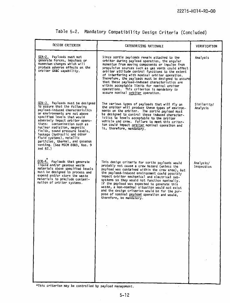
22215-H014-RO-00
Table 5-2. Mandatory Compatibility Design Criteria (Concluded)
DESIGN CRITERION CATEGORIZING RATIONALE VERIFICATION
GEN-2. Payloads must not Since sortie payloads remain attached to the Analysisgenerate forces, impulses or orbiter during payload operation, the angularmomentum changes which will momentum from moving components or impulse fromproduce adverse effects on the propulsive sources such as gas vents could affectorbiter GN&C capability. orbiter attitude control functions to the extent
of interfering with nominal orbiter operation.Therefore, the payloads must be designed to assurethat these payload-induced characteristics arewithin acceptable limits for nominal orbiteroperations. This criterion is mandatory toassure nominal orbiter operation.
GEN-3. Payloads must be designed The various types of payloads that will fly on Similarity/to assure that the following the orbiter will produce these types of environ- Analysispayload-induced characteristics ments on the orbiter. The sortie payload mustor environments are not above be designed to control these induced character-specified levels that would istics to levels acceptable to the orbiteradversely impact orbiter opera- vehicle and crew. Failure to meet this criter-tions: contamination such as ion could impact orbiter nominal operation andnuclear radiation, magnetic is, therefore, mandatory.fields, sound pressure levels,leakage (hydraulic and otherfluid systems), metallicparticles, thermal, and gaseousventing. (See MSCM 8080, Nos. 9and 62.)
GEN-4. Payloads that generate This design criteria for sortie payloads would Analysis/liquid and/or gaseous waste probably not cause a crew hazard (unless the Inspectionmaterials above specified levels payload was contained within the crew area), butmust be designed to process and the payload-induced environment could possiblyexpend and/or store the waste impact orbiter mechanical and electrical sub-materials to preclude contami- systems so they would not function nominally.nation of orbiter systems. If the payload was expected to generate this
waste, a non-nominal situation would not existand the design criterion would be for the pur-pose of nominal payload operation and would,therefore, be mandatory.
*This criterion may be controlled by payload management.
5-12

2221 5-H014-RO-00
Table 5-3. Discretionary Compatibility Design Criteria
DESIGN CRITERION CATEGORIZING RATIONALE VERIFICATION
INSTRUMENTATION
INST-2. Transducers must be This criterion is a choice of components used toselected to monitor at least the monitor the payload. This choice does notnominal operating range of the assure compatibility with the orbiter but possiblyparameter to be measured. Also, enables corrective action for a non-nominalto enhance problem resolution, occurrence. The effects of this criterion enhancetransducer ranges must extend far mission success from a ground flight controlenough beyond expected ranges to standpoint and is discretionary.allow monitoring of off-nominalconditions, but not so far as todegrade the granularity (resolu-tion) of the measurement.
INST-3. All parametric readouts This criterion is a configuration choice which isand displays required by the utilized to increase the possibility of missioncrew must be telemetered for success through ground mission-control activitiesindependent ground observation.
INST-4. Instrumentation must be This criterion is designed to preclude a non-provided to monitor and indicate nominal occurrence from impacting missionto the crew that a non-observ- success. Since this criterion is not requiredable function is either taking for basic compatibility or nominal operation,place or has been completed. it is considered discretionary.
INST-5. Commands affecting This design is a configuration choice to insure3ritical equipment status must payload mission success and is therefore cate-
have associated telemetry direct gorized as discretionary.from the commanded end item toprovide a positive functionalverification.
INST-6. Payload operation, This orbiter (crew) support element is a con-normalTy checked by direct figuration choice of payload monitoring capa-human senses, must be instru- bility and is discretionary.mented for shuttle missions.
ONBOARD CHECKOUT
OBCO-2. Payloads must be Payload developers may utilize this method ofdesigned recognizing that pay- payload checkout in lieu of instrumentationload viewing from the Mission or other checkout devices; thus affecting howSpecialist Station will be avail- the payload is designed. This is a configu-able to payloads for operational ration choice subject to cost-benefit analysischeckout. and is, therefore, discretionary.
STRUCTURES
STRU-10. Payloads which will be This sortie payload design criterion would belocate within pressurized com- imposed to protect the payload from an orbiter-partments of the orbiter must be induced environment (decompression). Sincedesigned to withstand rapid de- rapid decompression is not a nominal or plannedcompression to vacuum without occurrence, then the primary reason for thedamage to the payload equipment. criterion is to assure payload mission success(See MSCM 8080, No. 2, Rev A.) probability if this contingency situation does
occur. Therefore, the criterion is discretionary.
5-13
22215-HO14-RO-0
6. CONCLUSIONS
The results of this study will form the basis for detailed sortie
payload specifications to be written when quantitative shuttle data are
available. Utilization of the mandatory design criteria will help assure
that future shuttle sortie payloads will be compatible with the space
shuttle vehicle and help assure crew and hardware safety.
Since shuttle program management may concentrate only on those cri-
teria and specifications considered mandatory, considerable cost savings
can be realized by reduced manpower, less need for shuttle program mana-
gerial cognizance over certain criteria, and less paperwork. Also, when
new criteria are generated due to changes in subsystems, designs, or guide-
lines used by this study, the categorization processes can be used to aid
in managerial decision-making concerning these criteria.
6-1

22215-HO14-RO-00
REFERENCES
1. "Research and Applications Modules (RAM) Phase B Study," GDCA-DDA72-006 and 71x0030, Convair et al, 12 May 1972.
2. "Shuttle Orbital Applications and Requirements Follow-On (SOAR II),First Formal Progress Review," MSFC/McDonnell Douglas, August 1972.
3. "ALSEP Integrated Test Plan for Flight Configuration Array E,"ALSEP-TM-569, Bendix Aerospace, 24 March 1971.
4. "Design Criteria and Environments, LM (U)," LED 520-1, GrummanAerospace Corporation, 15 May 1963.
5. "Apollo Lunar Exploration Mission Experiment Instruments Performanceand Interface Specification Block 2-CSM," SD 69-315, North AmericanRockwell, 23 December 1969.
6. "General Requirements for Hardware Procurement," D2-118444-1, BoeingCompany, 21 July 1972.
7. "Apollo Applications Program Experiment Hardware General Require-ments," MSC-KA-D-68-1, Revision B, NASA/MSC, 27 January 1970.
8. "NASA CV-990 Laboratory Experimenters' Handbook," NASA/ARC, November1970.
9. "Scout Planning Guide," Vought, May 1971.
10. "Performance, Design and Verification Requirement for Experiment onGeneral Laboratory Equipment to be Selected for Project Sortie Labora-tory," (Preliminary), MSFC EC 006M 00000, NASA/MSFC, 23 June 1972.
11. "Delta Payload Planner's Guide," McDonnell Douglas, Rev. June 1970.
12. "Delta Spacecraft Design Restraints," DAC-61687, McDonnell Douglas,October 1968, Revision 1, December 1970.
13. "Orbiter/Payload Interface Control Document for the Space ShuttleSystem," IF 2556700, MSFC/McDonnell Douglas, et al, 30 June 1971.
14. "OGO-E-Experiment Interface Specification," D-13356-1 Revision E,TRW, 25 April 1966.
15. "Pioneer Program Specification, Spacecraft/Launch Vehicle InterfaceSpecification," PC-221.01, NASA/ARC, 1 April 1969.
R-1

22215-HO 4-RO-00
16. "Spacecraft/Scientific Instrument Interface, Pioneer F/G Project,"PC-220, NASA/ARC, 22 December 1969.
17. "Vela Advanced Spacecraft Program Specification, Spacecraft/PayloadInterface," IF 1-17, TRW, 31 March 1966.
18. "Vela Advanced Spacecraft Program Specification, Spacecraft/SubsystemInterface," IF 2-1C, TRW, 14 April 1967.
19. "HEAO Interface Control Documents," NASA/MSFC,* MSFC 72M23006, 22 August 1972* MSFC 72M21007, 9 August 1972* MSFC 72M21157, 9 August 1972.
20. "EOS Payload Interface Definition," TOR-0059(6758-02)-1, AerospaceCorporation, 1 July 1970.
21. "Shuttle/Agena Compatibility Study," (Final Presentation), D15 2751,Lockheed Missiles and Space Corporation, 18 January 1972.
22. "LEM Scientific Equipment GFE Performance and Interface Specifica-tion," LSP-360-11, Grumman Aerospace Corporation, 18 March 1966.
23. "Manned Spacecraft Criteria and Standards," MSCM 8080, NASA/MSC,26 April 1971.
24. "Space Shuttle Baseline Accommodations for Payloads," MSC 06900,NASA/MSC, 27 June 1972.
R-2

22215-H014-RO-O0
BIBLIOGRAPHY
"ALSEP Integrated Test Plan for Flight Configuration Array E,"
ALSEP-TM-569, Bendix Aerospace, 24 March 1971.
"Apollo Applications Program Experiment Hardware General Require-
ments," MSC-KA-D-68-1, Revision B, NASA/MSC, 27 January
1970.
"Apollo Ground Support Equipment General Environmental Criteria and
Test Specification," MSC-GSE-lB, Revision 1, NASA/MSFC,
23 June 1964.
"Apollo Lunar Exploration Mission Experiment Instruments Performance
and Interface Specification Block 2-CSM," SD 69-315,North American Rockwell, 23 December 1969.
"Apollo Test Requirements," NHB 8080.1, NASA, March 1967.
"Centaur Payload User's Manual," NASA CR-72109, General DynamicsConvair Division, August 1966.
"Delta Payload Planner's Guide," McDonnell Douglas, Rev. June 1970.
"Delta Spacecraft Design Restraints," DAC-61687, McDonnell Douglas,
October 1968, Revision 1, December 1970.
"Design Criteria and Environments, LM (U)," LED 520-1, Grumman
Aerospace Corporation, 15 May 1963.
"Design Handbook for Aerospace System, General-Electromagnetic
Compatibility," AFSC DH 1-4, DOD/Air Force, 10 January
1969.
"Design Requirements for Shuttle Payloads," NASA Memo from Dale D.Myers to Philip E. Culbertson, 23 February 1973.
"Electromagnetic Compatibility," MSFC-SPEC-279, NASA/MSFC, November1967.
"Electromagnetic Interference Characteristics, Measurement of,"MIL-STD-462, DOD, 9 February 1971.
R-3

22215-H014-RO-O0
bIBLIOGRAPHY (Continued)
"Electromagnetic Interference Characteristics, Requirements for
Equipment," MIL-STD-461A, DOD, 1 August 1968.
"EOS/Payload Interface Definition," TOR-0059(6758-02)-1, Aerospace
Corporation, 1 July 1970.
"General Requirements for Hardware Procurement," D2-118444-1, Boeing
Company, 21 July 1972.
"General Specification for Airborne Electronic Equipment," MIL-E-
5400 N, DOD, 30 November 1971.
"HEAO Interface Control Documents"
* MSFC 72M23006, 22 August 1972* MSFC 72M21007, 9 August 1972* MSFC 72M21157, NASA/MSFC, 9 August 1972
"Human Engineering Design Criteria for Military Systems, Equipment,
and Facilities," MIL-STD-1472A, Revision 1, DOD, 15 May
1970.
"In-Place Calibration Indicating Instrumentation: Hypergolic Fuels
and Oxidizer Tankers," GP-837, NASA/KSC, 25 March 1970.
"Interface Control Documents Aeronautical Equipment," MIL-I-2660 (2)
and ISC-ASPO-EMI-1OA, DOD and NASA/MSC, October 1963.,
"KSC Standards and Calibration Manual," GP-730, NASA/KSC, 15
November 1969.
"Laboratory Branch Facilities, Equipment and Capabilities Manual,"
GP-839, NASA/KSC, 15 April 1970.
"LEM Scientific Equipment GFE Performance and Interface Specifi-
cation," LSP-360-11, Grumman Aerospace Corporation,18 March 1966.
"Manned Spacecraft Criteria and Standards," MSCM 8080, NASA/MSC,
26 April 1971.
I"MOL Program Structural Criteria for the Laboratory Vehicle Segment,"TOR 1001 (2107-30)-3, Aerospace Corporation, December 1966.
R-4

22215-H014-RO-00
BIBLIOGRAPHY (Continued)
"NASA CV-990 Laboratory Experimenters' Handbook," NASA/ARC, November
1970.
"OGO-E Experiment Interface Specification," D-13356-1 Revision E,
TRW, 25 April 1966.
"Orbiter/Payload Interface Control Document for the Space Shuttle
System," IF 2556700, MSFC/McDonnell Douglas et al, 30 June
1971.
"Performance, Design and Verification Requirement for Experiment on
General Laboratory Equipment to be Selected for Project
Sortie Laboratory" (Preliminary), MSFC EC 006M 00000,
NASA/MSFC, 23 June 1972.
"Pioneer Program Specification, Spacecraft/Launch Vehicle Interface
Specification," PC-221.01, NASA/ARC, 1 April 1969.
"Proceedings of the Space Shuttle Sortie Workshop," NASA/GSFC,
31 July - 4 August 1972.
"Research and Applications Modules(RAM) Phase B Study," GDCA-DDA72-
006 and 71X0030, Convair et al, 12 May 1972.
"Reference Earth Orbital Search and Applications Investigations
(Blue Book)," NHB 7150.1, NASA, January 1971.
"Scout Planning Guide," Vought, May 1971.
"Shuttle/Agena Compatibility Study" (Final Presentation), D015 2751,
Lockheed Missiles and Space Corporation, 18 January 1972.
"Shuttle Orbital Applications and Requirements Follow-On (SOAR II),
First Formal Progress Review," MSFC/McDonnell Douglas,
August 1972.
"Shuttle Orbiter/Payloads Monitor and Control Interface Study," SD 72-
SA-0043, North American Rockwell, 1 May 1972.
R-5
22215-HO14-RO-00
BIBLIOGRAPHY (Concluded)
"Sortie Lab Guidelines and Constraints Level I," NASA, 15 August1972.
"Spacecraft/Scientific Instrument Interface, Pioneer F/G Project,"PC-220, NASA/ARC, 22 December 1969.
"Space Shuttle Baseline Accommodations for Payloads," MSC 06900,NASA/MSC, 27 June 1972.
"Standard General Requirements for Electronic Equipment," MIL-STD-454 C, DOD, 15 October 1970.
"Technical Manual Apollo/Saturn Operations and Maintenance ManualGaseous Hydrogen Detection System Cryogenics BuildingNo. 2," TM-591, NASA/KSC, 31 August 1969.
"Technical Manual Apollo/Saturn Operations and Maintenance ManualGaseous Hydrogen Detection System East Altitude Chamber0 & C Building," TM-575, Revision 1, NASA/KSC, 30 September1969.
"Testing Compatibility of Materials for Liquid Oxygen Systems"(Amendment 1), MSFC-SPEC-106B, NASA/MSFC, 6 October 1967.
"Test Report for J-Mission Experiments Data Systems Integrated Test,CSM-112 Configuration-ATEE Lab," 70-072, North AmericanRockwell, 15 November 1970.
"The KSC Television Data Display (TDDS)," GP-965, NASA/KSC,3 January 1972.
"Titan IIIC Payload User's Guide," MCR-68-62 Rev. 2, Martin MariettaCorporation, 7 October 1969.
"Vela Advanced Spacecraft Program Specification, Spacecraft/PayloadInterface," IF 1-17, TRW, 31 March 1966.
"Vela Advanced Spacecraft Program Specification, Spacecraft/SubsystemInterface," IF 2-1C, TRW, 14 April 1967.
"What Made Apollo A Success?" NASA SP-287, NASA, 1971.
R-6