
ARMINES, BME, UNINOVAapi.ning.com/files/zxy*xRp5iQ4ZSO*nuXiqeTaUahACYmL*3cIJI4X5f5... · ARMINES...
47
Project Number 611125 D3.2 – Scalable query and transformation engine Version 1.0 18 May 2015 Final Public Distribution ARMINES, BME, UNINOVA Project Partners: ARMINES, Autonomous University of Madrid, BME, IKERLAN, Soft-Maint, SOFTEAM, The Open Group, UNINOVA, University of York Every effort has been made to ensure that all statements and information contained herein are accurate, however the Project Partners accept no liability for any error or omission in the same. © 2015 Copyright in this document remains vested in the MONDO Project Partners.
Transcript of ARMINES, BME, UNINOVAapi.ning.com/files/zxy*xRp5iQ4ZSO*nuXiqeTaUahACYmL*3cIJI4X5f5... · ARMINES...
Project Number 611125
D3.2 – Scalable query and transformation engine
Version 1.018 May 2015
Final
Public Distribution
ARMINES, BME, UNINOVA
Project Partners: ARMINES, Autonomous University of Madrid, BME, IKERLAN, Soft-Maint,SOFTEAM, The Open Group, UNINOVA, University of York
Every effort has been made to ensure that all statements and information contained herein are accurate, howeverthe Project Partners accept no liability for any error or omission in the same.
© 2015 Copyright in this document remains vested in the MONDO Project Partners.

D3.2 – Scalable query and transformation engine
Project Partner Contact Information
ARMINES Autonomous University of MadridMassimo Tisi Juan de LaraRue Alfred Kastler 4 Calle Einstein 344070 Nantes Cedex, France 28049 Madrid, SpainTel: +33 2 51 85 82 09 Tel: +34 91 497 22 77E-mail: [email protected] E-mail: [email protected]
BME IKERLANDaniel Varro Salvador TrujilloMagyar Tudosok korutja 2 Paseo J.M. Arizmendiarrieta 21117 Budapest, Hungary 20500 Mondragon, SpainTel: +36 146 33598 Tel: +34 943 712 400E-mail: [email protected] E-mail: [email protected]
Soft-Maint SOFTEAMVincent Hanniet Alessandra BagnatoRue du Chateau de L’Eraudiere 4 Avenue Victor Hugo 2144300 Nantes, France 75016 Paris, FranceTel: +33 149 931 345 Tel: +33 1 30 12 16 60E-mail: [email protected] E-mail: [email protected]
The Open Group UNINOVAScott Hansen Pedro MalóAvenue du Parc de Woluwe 56 Campus da FCT/UNL, Monte de Caparica1160 Brussels, Belgium 2829-516 Caparica, PortugalTel: +32 2 675 1136 Tel: +351 212 947883E-mail: [email protected] E-mail: [email protected]
University of YorkDimitris KolovosDeramore LaneYork YO10 5GH, United KingdomTel: +44 1904 32516E-mail: [email protected]
Page ii Version 1.0Confidentiality: Public Distribution
18 May 2015
Contents
1 Reactive ATL 4
1.1 Use Cases . . . . . . . . . . . . . . . . . . . . . . . . . . . . . . . . . . . . . . . . 6
1.1.1 Reactive views in BIM . . . . . . . . . . . . . . . . . . . . . . . . . . . . . 6
1.1.2 Illustrative example . . . . . . . . . . . . . . . . . . . . . . . . . . . . . . . 7
1.2 Reactive Model Transformation . . . . . . . . . . . . . . . . . . . . . . . . . . . . 9
1.3 A Reactive Engine for ATL . . . . . . . . . . . . . . . . . . . . . . . . . . . . . . . 11
1.3.1 Reactive-EMF . . . . . . . . . . . . . . . . . . . . . . . . . . . . . . . . . 11
1.3.2 Reactive-ATL . . . . . . . . . . . . . . . . . . . . . . . . . . . . . . . . . . 12
1.4 Using Reactive Transformations . . . . . . . . . . . . . . . . . . . . . . . . . . . . 15
1.5 Evaluation . . . . . . . . . . . . . . . . . . . . . . . . . . . . . . . . . . . . . . . . 18
1.5.1 Synthesized benchmarks . . . . . . . . . . . . . . . . . . . . . . . . . . . . 18
1.5.2 Real-world Benchmarks . . . . . . . . . . . . . . . . . . . . . . . . . . . . 21
1.5.3 Language Limitations . . . . . . . . . . . . . . . . . . . . . . . . . . . . . 21
1.5.4 Prototype framework limitations . . . . . . . . . . . . . . . . . . . . . . . . 23
2 VIATRA3-CEP:Streaming Model Transformations By Complex Event Processing 24
2.1 Case study: gesture recognition by live models . . . . . . . . . . . . . . . . . . . . 25
2.2 Overview of the approach . . . . . . . . . . . . . . . . . . . . . . . . . . . . . . . . 27
2.2.1 A taxonomy of structural model changes . . . . . . . . . . . . . . . . . . . 27
2.2.2 Changes, events and streaming transformations . . . . . . . . . . . . . . . . 28
Model queries for structural constraints . . . . . . . . . . . . . . . . . . . . 28
Defining atomic events . . . . . . . . . . . . . . . . . . . . . . . . . . . . . 29
Defining complex events . . . . . . . . . . . . . . . . . . . . . . . . . . . . 30
Defining transformation rules . . . . . . . . . . . . . . . . . . . . . . . . . 31
2.2.3 Detecting complex events . . . . . . . . . . . . . . . . . . . . . . . . . . . 31
iii

D3.2 – Scalable query and transformation engine
2.3 Architecture and use of the prototype tooling . . . . . . . . . . . . . . . . . . . . . 32
2.3.1 Architectural overview . . . . . . . . . . . . . . . . . . . . . . . . . . . . . 32
2.3.2 Sample execution of the case study . . . . . . . . . . . . . . . . . . . . . . 34
2.4 Evaluation . . . . . . . . . . . . . . . . . . . . . . . . . . . . . . . . . . . . . . . . 35
Page iv Version 1.0Confidentiality: Public Distribution
18 May 2015

D3.2 – Scalable query and transformation engine
Document Control
Version Status Date0.1 Document outline 10 December 20140.2 First draft 14 February 20150.7 Full draft 25 March 20150.9 Revision after reviews 27 April 20151.0 Final version 18 May 2015
18 May 2015 Version 1.0Confidentiality: Public Distribution
Page v
D3.2 – Scalable query and transformation engine
Executive Summary
Model-driven applications may maintain large networks of structured data models and transforma-tions among them. The development of such applications is complicated by the need to reflect on thewhole network any runtime update performed on models or transformation logic. If not carefully de-signed, the execution of such updates may be computationally expensive. In MONDO we proposetwo complementary approaches to address these challenges.
In Chapter 1, we propose reactive paradigm for programming model transformations, and we imple-ment a reactive model-transformation language. We argue that this paradigm facilitates the devel-opment of autonomous model-driven systems that react to update and request events from the hostapplication by identifying and performing only the needed computation. We implement such ap-proach by providing a reactive engine for the ATL transformation language. We evaluate the usagescenarios that this paradigm supports and we experimentally measure its ability to reduce computa-tion time in transformation-based applications.
In Chapter 2, we address streaming model transformations that represent a novel class of transforma-tions dealing with models whose elements are continuously produced or modified by a backgroundprocess [37]. Executing streaming transformations requires efficient techniques to recognize the acti-vated transformation rules on a potentially infinite input stream. Detecting a series of events triggeredby compound structural changes is especially challenging for a high volume of rapid modifications,a characteristic of an emerging class of applications built on runtime models. We propose a novel ap-proach for streaming model transformations by combining incremental model query techniques withcomplex event processing (CEP) and reactive (event-driven) transformations. The event stream is au-tomatically populated from elementary model changes by the incremental query engine, and the CEPengine is used to identify complex event combinations, which are used to trigger the execution oftransformation rules. We demonstrate our approach in the context of automated gesture recognitionover live models populated by KINECT sensor data.
Related Work
Reactivity outside MDE. Reactive programming is a subject largely studied out of the modellingresearch community. As an example, the ESTEREL [7] synchronous language, designed to programcomplex reactive systems and Reactive-C [9], an extension of the C programming language followingthe same paradigm, reached a high level of popularity. Reactive programming has also been studiedin relation to functional languages. [46] studies the semantics of functional reactive programmingsystems.
Chapter 1 of this deliverable is inspired by similar efforts in the attribute grammar research commu-nity. In [35], the authors describe incremental evaluations through caching visit sequence functions.Moreover, instead of explicitly representing the tree, it is represented through a set of visit functionscorresponding to its successive visits. Then, they only visit the parts of the tree that need to be read.This can be regarded as similar to the lazy model presented in this deliverable. In [45], visit func-tions are used instead of visit sequences in order to achieve efficient incrementality. More recently
18 May 2015 Version 1.0Confidentiality: Public Distribution
Page 1
D3.2 – Scalable query and transformation engine
and for an specific kind of attribute grammars, in [11], the author presents an approach for incremen-tal evaluation based, as in the present work, on cache invalidation. They achieve incrementality bykeeping pointers from a place in the tree where a field is written to the place in the tree where the ob-ject being written was created. Then pointers from the creation point to the places where the objectsare read are also kept. If a change happens, these pointers are used to invalidate the cache.
[38] follows a lazy approach for the evaluation of XSLT. The authors provide an interpreter for XSLTthat allows random access to the transformation result. They also show how their implementationenables efficient pipelining of XSLT transformations.
The implementation of a lazy evaluator for functional (navigation) languages is a subject with a longtradition [28]. We refer the reader to [27] for an example based on Lisp.
Reactivity in MDE. Chapter 1 of this deliverable builds upon the two works: [30] and [41], by thesame authors, where incrementality and on-demand execution are studied. Here we add a systematicclassification of the model transformation scenarios that benefit/require these features and provide anapproach that combines both solutions to cover all scenarios.
Model incremental synchronization has been extensively studied in the modeling community. [48]proposes an automatic way to synchronize the source and target models of an ATL transformationoffline. Incrementality is implemented by interfacing with existing differencing tools for calculatingchanges to the models and propagating them bidirectionally. With respect to their work, the approachfollowed in [30] requires only limited changes to the ATL compiler and no change to the ATL Vir-tual Machine (VM), whereas they rely on several VM modifications. We follow here the approachproposed in [30] for tracking OCL expressions in order to calculate the affected target elements of asource model update.
In an alternative approach, Hearnden et al. [25] synchronize two models incrementally, by using adeclarative logic-based transformation engine. The approach records a transformation execution andlinks each transformation step to the correspondent changes in the source model. This information isthen used for change propagation.
Live and offline incrementality has been already implemented with Graph Transformations tech-niques, for example in [4]. Especially the work in [36] implements live incrementality, based onthe Rete algorithm, a well-known technique in the field of rule-based systems. These graph trans-formation approaches focus on incremental pattern-matching to improve the performances of thetransformation. In opposition to these graph-based systems, the proposal we follow does not directlyapply in-place transformations, but it could be extended for that purpose. In this sense the proposalwe are building on is more similar to [23], that employs Triple Graph Grammars for incrementaloffline model synchronization in both directions.
Regarding on-demand generation and fine grained control of transformation execution, the Stratego[43] system allows user-defined execution strategies for transformation rules, whereas VIATRA eval-uates lazily the matchings of connected rules to avoid unnecessary computation, as described in [40].While user-defined strategies have been used to implement target-driven approaches [47] and somelimited lazy evaluation has been provided, the activation of rules as answer to external consumptionhas been only addressed in [41]. In that mentioned work target model request tracking and caching
Page 2 Version 1.0Confidentiality: Public Distribution
18 May 2015

D3.2 – Scalable query and transformation engine
support is implemented in an ad-hoc way. Here, we tackle the support for these two features in amore generic way and we add support for cache invalidation.
Lazy evaluation has been explored for OCL in [2] and in [16] where performance measures arepresented. The topic of evaluating OCL expression incrementally has been investigated by Cabot[14], especially for detecting if a modification to a UML model violates constraints that were satisfiedbefore.
Streaming model transformations. In [37] the authors present streaming transformations workingon a stream of model fragments and elements. In contrast to this technique, our approach leveragesderived information regarding the model in the form of change events, which decouples the executionfrom the actual model. Consequently, the issues discussed in [37] (e.g. dealing with references amongmodel elements and transformation scheduling) are not present in our case.
The concept of change-driven transformations is proposed in [6] for executing transformations onchange models as input or output. Our approach extends this approach since identifying complexmodel changes enables CDTs of higher granularity and also enables the integration of complex eventprocessing. Live models used in the current report are different from living models [12], while thechange pattern formalism is reused from [6], a similar formalism was proposed in [49]. A formalfoundation of infinite models is presented in [17] by redefining OCL operators over infinite collec-tions. This is complementary problem as the models themselves are finite in our case, but theirlifeline is infinite due to high frequency model changes.
Complex event processing. ESPER [21] is an open source event processing engine. It has beenemployed in our preliminary work [19], presented at the EclipseCon Europe 2012. Despite being ahigh-end CEP engine concerning its performance and the descriptive power of its language, support-ing the scenarios like those presented in [37] is cumbersome and infeasible.
Other open CEP engines (e.g. StreamBase, Drools Fusion) can also be considered but integration intoan existing MDE tooling remains a significant technical challenge since defining change patterns andfeeding model (change) information into the engine requires significant programming effort. Theintegrated approach presented in this report (classified as a detection-oriented CEP) overcomes thisissue by providing a language supporting directly referencing graph patterns and organizing theminto complex event patterns.
Processing runtime models. Processing of runtime models may introduce somewhat related chal-lenges. Incremental model transformations are used in [44] for efficient runtime monitoring. Song etal. introduced incremental QVT transformations [39] for runtime models. However, these techniquesprimarily focus on obtaining a faithful model of the running system, while they do not consider eventstreams or complex event processing over live models.
Context-aware systems [1] introduce novel challenges for model transformations where not onlybusiness-relevant data needs to be processed, but also data from the context or environment of thesystem. Our approach could be a feasible solution to execute model-transformations in a context-aware fashion, e.g. in cyber-physical systems where environmental data gathered by the sensorscould affect the overall transformation process.
18 May 2015 Version 1.0Confidentiality: Public Distribution
Page 3
Chapter 1
Reactive ATL
Model-driven applications, i.e. applications based on explicit structured data models, are becomingwide-spread within both the academic and industrial worlds. Modeling frameworks like EMF (theEclipse Modeling Framework 1) simplify the development of such applications by providing a stan-dard representation and interface to the data structure (i.e., the model), code generation facilities,scalable serialization and interoperability with several other model-driven tools. Modeling frame-works are extensively used in a wide range of scenarios2 and even the Eclipse 4 platform is itselfdeveloped on EMF3.
Model-driven applications manipulate models by executing model transformations, defined us-ing general-purpose languages (GPLs, e.g., Java), or domain-specific languages called model-transformation languages (MTLs). Popular MTLs like the Object Management Group (OMG) QVT(Query/View/Transformation) [34] and the AtlanMod Transformation Language (ATL) [29] are sup-posed to provide a higher level of abstraction and expressiveness in describing the transformationas a relationship among source and target model elements. In a typical model-driven application,the application logic results separated in two parts: 1) transformations specify how to derive targetmodels from source models, 2) the host application defines what (i.e., which model elements) tocompute, when, and why (e.g., in response to which events). The application is responsible of ex-plicitly executing the transformations, seen as black-box functions that return the computed targetmodels.
In MONDO we argue that MTLs, when provided with a specific execution environment, enable abeneficial shift of paradigm for programming model-driven applications towards reactive program-ming. Reactive programming[24] denotes a programming paradigm oriented towards the propagationof changes through data-flows. A reactive programming language, in this broad sense, is a languagewhose programs automatically update their computation whenever some input data changes. In ourmodel-driven context we propose a paradigm where a network of reactive transformations definespersistent data-flows among models. A reactive transformation engine takes care of activating onlythe strictly needed computation in response to updates or requests of model elements. Computa-
1www.eclipse.org/emf/2http://en.wikipedia.org/wiki/List_of_Eclipse_Modeling_Framework_based_
software3http://www.eclipse.org/e4/resources/e4-whitepaper.php
4
D3.2 – Scalable query and transformation engine
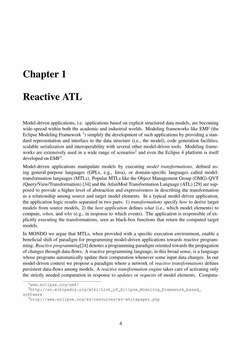
Figure 1.1: The transformation chain Class2Relational + Relational2XML
tion is updated when necessary, in an autonomous and optimized way. The application architectureresults deeply changed, since the host application does not directly control the execution of the trans-formations anymore, but only accesses or updates the underlying models.
We want to argue that reactive transformation systems have the following benefits:
1. The development of the host application is simplified, since the application relinquishes re-sponsibility over when and what to transform. However, despite this loss of control, the re-active transformation engine can be used for an efficient implementation of all the applicationscenarios of traditional transformation engines.
2. The amount of computation to perform is automatically minimized, allowing for more efficientapplications in several scenarios, w.r.t. traditional transformation systems.
We support our arguments by implementing a reactive engine for the ATL language4, evaluating itsapplication to different usage scenarios and experimentally assessing the performance gain w.r.t. thestandard ATL engine in the same application. For implementing our reactive transformation enginefor ATL we build on our previous work, where we studied the possibility to apply incrementality [30]and lazy evaluation [41] to model transformations. In MONDO we design a transformation systemthat reacts to both updates and requests, by integrating incrementality and lazy evaluation as dualaspects of reactive transformation. In addition, our system is able to react to updates to the modeltransformation code itself, by identifying the computation needed to keep the whole transformationnetwork consistent.
The rest of the chapter is organized as follows. Section 1.1 presents a running example and Sec-tion 1.2 describes our proposed approach. Section 1.3 illustrates the corresponding implementationwhereas Section 1.4 evaluates the application scenarios that our engine can address. Section 1.5shows the results of a performance evaluation on these scenarios.
18 May 2015 Version 1.0Confidentiality: Public Distribution
Page 5
D3.2 – Scalable query and transformation engine
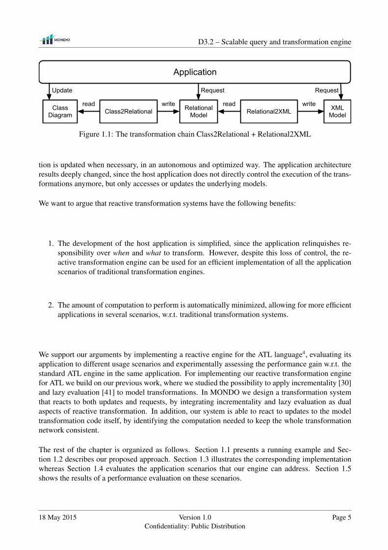
Figure 1.2: Class diagram and ER metamodels
1.1 Use Cases
1.1.1 Reactive views in BIM
Among the use cases identified in the MONDO project a reactive transformation engine would pro-vide a solution for scalability in view creations on the BIM scenario for construction industry.
The construction industry has traditionally communicated building construction information (sites,buildings, floors, spaces, and equipment and their attributes) through drawings with notes and spec-ifications. BIM (Building Information Model), a CAD (Computer Aided Design) method, came toautomate that process and enhance its operability according to different tools, actors, etc. within theAECO (Architecture, Engineering, Construction, and Operations) industry. A BIM model is a multi-disciplinary data specific model instance which describes all the information pertinent to a buildingand its components. It is described using the IFC (Industry Foundation Classes) specification, a freelyavailable format to describe, exchange, and share information typically used within the building andfacility management industry sector.
Intrinsically, the IFC model is expressed using the EXPRESS data definition language, defined asISO10303-11 by the ISO TC184/SC4 committee. EXPRESS representations are known to be com-pact and well suited to include data validation rules within the data specification.
The IFC model is necessarily large and complex, as it includes all common concepts used in build-ing industry projects, from feasibility analysis, through design, construction, and operation of a builtfacility. As IFC models definition involves a considerable collaboration and requirements exchangebetween different stakeholders in building industry, a handful coordination scheme is a key to produc-tive collaboration. Model View Definition, MVD, defines a subset of the IFC schema, that is neededto satisfy one or many Exchange Requirements of the AEC industry. MVDs include three primary de-liverables, each using standard formats. These are: (i) MVD Overview/Description which describesthe scope of the MVD, (ii) MVD Diagrams which define the MVD Concepts that will be used inthe exchange, as well as the structure and relationships between these Concepts, and (iii) ConceptImplementation Guidance (which defines the IFC entities used to exchange each concept and the Im-plementer agreements that general reduce the implementation scope that would otherwise be required
4The full code of Reactive-ATL and the running case can be found at the address: http://www.emn.fr/z-info/atlanmod/index.php/Reactive-ATL
Page 6 Version 1.0Confidentiality: Public Distribution
18 May 2015
D3.2 – Scalable query and transformation engine
by the extremely general IFC schema). The BuildingSmart foundation has developed and made avail-able a set of MDVs for IFC4 and IFC2x3 (http://www.buildingsmart-tech.org/specifications/ifc-view-definition). These specifications give a clear insight about the mandatory or optional concepts thatshould be kept to satisfy a particular exchange requirement. The Coordination View has been the firstview definition developed by buildingSMART International and is currently the most implementedview of the IFC schema. This view targets the coordination between the architectural, mechanicaland structural engineering tasks during the design phase. It contains definitions of spatial structure,building, and building service elements that are needed for coordinating design information amongthese disciplines.
In the MONDO BIM use case, we rely on these specifications to build view transformations in ATL.Given the size of BIM models, that can reach several GBs, we want the MVD view to be computed ondemand, only for the strictly necessary part. The user would navigate the view in their own editor anda reactive system would catch the model-element requests from the editor and activate the minimalcomputation for generating them from the source model.
1.1.2 Illustrative example
In order to simplify the illustration of the reactive transformation engine, we introduce another sce-nario, very simple, concerning the development of an ideal database schema editor based on modeltransformations (see Figure 1.1). The developer in charge of producing such application should pro-vide the user with an editor of the conceptual model of the database (in the form of a UML ClassDiagram) and use a model transformation that generates a corresponding relational model (i.e., theClass2Relational transformation). The developer then provide the user with the capability of brows-ing the relational model in read-only mode. Additionally, the developer may also provide means forthe relational model to be transformed to an XML model or to SQL code in order to facilitate inter-operability, code-generation and/or report generation tasks. Thus, our ideal database schema editormay constitute a transformation chain as we can see in Figure 1.1 (the class diagram model, rela-tional model, XML model and SQL code can, in turn, be part of other more complex transformationnetworks).
In this scenario, updates of the source class diagram and inspection of its corresponding relationalmodel may occur often. Therefore, in order to reduce the amount of work to be performed by thetransformation chain, it would be desirable to be able to: 1) when the user modifies the ConceptualUML model, propagate only the changes to the affected elements in the Relational Model, 2) whilereading the Relational Model, perform the transformation and updates w.r.t. possible changes in theConceptual UML model, in an on-demand basis, so that unread Relational Model elements do nottrigger any uneeded transformation evaluation. Summarizing, it would be desirable for the trans-formation chain to perform source updates in an incremental manner and target model requests in aLazy manner. Adding a given Class should only require the transformation to the corresponding Ta-ble (and then, the corresponding XML element) and the update of the elements using that informationin the target models. Reading the Columns of a given table should only trigger the transformationcalculations for that Table, ignoring other existing Tables until they are requested.
In Fig. 1.2, we show the source and target metamodels of the Class2Relational transformation.The ClassDiagram metamodel represents a very simplified UML Class diagram. In this metamodel,
18 May 2015 Version 1.0Confidentiality: Public Distribution
Page 7

D3.2 – Scalable query and transformation engine
Packages are containers of Classifiers that are either Datatypes or Classes. Classes can, in turn,be containers of Attributes, which can be multivalued. The Relational metamodel describes sim-ple relational schemas. Schema contains Tables that are composed of Columns. Columns have atype that characterizes the kind of elements they can hold. Listing 1.1 shows the main rules of theClass2Relational transformation written in ATL.
Listing 1.1: ATLClass2Relational transformation.
r u l e Package2Schema{fromp :ClassDiagram !Package
toout :Relational !Schema (
ownedElements<−p .ownedElement−>select (e | e .↪→oclIsTypeOf (ClassDiagram !Class ) )
)}
r u l e Class2Table {fromc :ClassDiagram !Class
toout :Relational !Table (
name<−c .name ,col<−Sequence {key}−>union (c .attr−>select (e | not e .multiValued )
↪→ ) ,key<−Set{key}
) ,key :Relational !Column (name<−’objectId’)
}
r u l e DataType2Type {fromdt :ClassDiagram !DataType
to
out :Relational !Type (name <− dt .name
)}
r u l e DataTypeAttribute2Column {froma :ClassDiagram !Attribute (a .type .oclIsKindOf (ClassDiagram !DataType )
↪→andnot a .multiValued)toout :Relational !Column (name <− a .name ,type <− a .type
)}
r u l e ClassAttribute2Column {froma :ClassDiagram !Attribute (a .type .oclIsKindOf (ClassDiagram !Class ) andnot a .multiValued
)to
foreignKey :Relational !Column (name <− a .name + ’Id’ ,
)}
The ATL transformation constitutes a set of rules that describe how parts of the input model generateparts of the target model. These rules must have an input pattern and an output pattern. E.g., in therule ClassAttribute2Column input model elements of type Attribute are selected to be transformedinto output elements of type Column. Rules can have filters and bindings. Filters are used to imposeconditions on the input elements selected by the input pattern and bindings are used to initialize valuesof the elements created by the output pattern. For instance, in rule DataTypeAttribute2Column, a filteris introduced to select only Attributes that are not multivalued and whose type is Class. Two bindingsare then used to initialize the name and type of the created Column. Rule Class2Table creates aTable for each Class, adds a key Column and initializes the list of columns with the respectivelytransformed Attributes. Finally, rule Package2Schema transforms a Package into a relational Schemaand initializes the list of Tables.
For simplicity, in the following sections we limit the discussion to applications based on 1-to-1 uni-directional transformations, analogous to Figure 1.1. This kind of application maintains a singlesource model. The model is then manipulated by a transformation chain, but the generated models
Page 8 Version 1.0Confidentiality: Public Distribution
18 May 2015
D3.2 – Scalable query and transformation engine
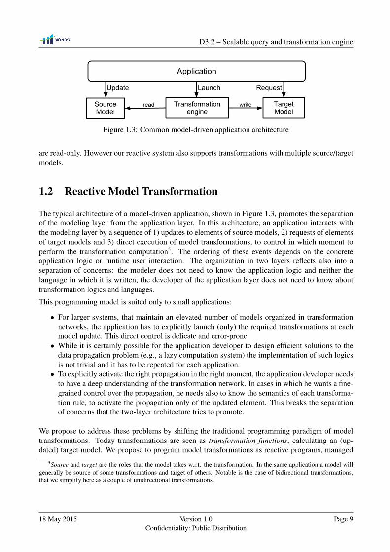
Figure 1.3: Common model-driven application architecture
are read-only. However our reactive system also supports transformations with multiple source/targetmodels.
1.2 Reactive Model Transformation
The typical architecture of a model-driven application, shown in Figure 1.3, promotes the separationof the modeling layer from the application layer. In this architecture, an application interacts withthe modeling layer by a sequence of 1) updates to elements of source models, 2) requests of elementsof target models and 3) direct execution of model transformations, to control in which moment toperform the transformation computation5. The ordering of these events depends on the concreteapplication logic or runtime user interaction. The organization in two layers reflects also into aseparation of concerns: the modeler does not need to know the application logic and neither thelanguage in which it is written, the developer of the application layer does not need to know abouttransformation logics and languages.
This programming model is suited only to small applications:
• For larger systems, that maintain an elevated number of models organized in transformationnetworks, the application has to explicitly launch (only) the required transformations at eachmodel update. This direct control is delicate and error-prone.• While it is certainly possible for the application developer to design efficient solutions to the
data propagation problem (e.g., a lazy computation system) the implementation of such logicsis not trivial and it has to be repeated for each application.• To explicitly activate the right propagation in the right moment, the application developer needs
to have a deep understanding of the transformation network. In cases in which he wants a fine-grained control over the propagation, he needs also to know the semantics of each transforma-tion rule, to activate the propagation only of the updated element. This breaks the separationof concerns that the two-layer architecture tries to promote.
We propose to address these problems by shifting the traditional programming paradigm of modeltransformations. Today transformations are seen as transformation functions, calculating an (up-dated) target model. We propose to program model transformations as reactive programs, managed
5Source and target are the roles that the model takes w.r.t. the transformation. In the same application a model willgenerally be source of some transformations and target of others. Notable is the case of bidirectional transformations,that we simplify here as a couple of unidirectional transformations.
18 May 2015 Version 1.0Confidentiality: Public Distribution
Page 9

D3.2 – Scalable query and transformation engine
Reactivemodel
Reactivemodel
Transformationengine
requestnotification
updatenotification
Application
Update Request
operation
Reactive System
read
Figure 1.4: Reactive transformation system
by a reactive engine. A reactive transformation engine would autonomously activate the computationin answer to external events, taking complete charge of data propagation in the model driven sys-tem. For a model-transformation system these events are model updates and requests coming fromthe application layer, along with changes to the transformation itself.
The traditional advantages of reactive programming apply also to the model-transformation case:
• when dealing with complex propagation networks, a reactive engine frees the application de-veloper from designing the propagation system; The same is true for the higher-order case,where updates occur to the transformation itself.• the engine provides an optimized propagation mechanism, using strategies like lazy and partial
evaluation, whose implementation would be too expensive for the application developer; theengine can perform the propagation at arbitrary granularity, while fine-grained propagationsystems would be more difficult to implement for the application developer;• the developer can focus on describing the rest of the application and does not have to get in
contact with the transformation logic or even with the transformation language.
Our proposed architecture for reactive transformation systems is represented in Figure 1.4. A reactivesystem is made of two components: a reactive modeling framework (i.e., the interface to interact withsource and target reactive models) and a reactive transformation engine.
To be able to react to modeling events, the transformation engine has to intercept them.
This task is performed by 1) the modeling framework, that receives updates and requests from theapplication. Hence we have to substitute a standard modeling framework (e.g., EMF) with a re-active version that communicates to the transformation engine the arrival of events. The reactivetransformation engine will then be responsible of calculating the transformation computation thatneeds to be updated. 2) the transformation framework itself, that receives updates to the transforma-tion definition. As with model changes, the reactive transformation engine will then be responsibleof calculating the transformation computation that needs to be updated in order to synchronize anongoing transformation operation with the new transformation definition.
Having a single standard modeling framework accessed by all the applications in a technical space isa crucial aspect of model-driven engineering. To maintain interoperability with the technical space
Page 10 Version 1.0Confidentiality: Public Distribution
18 May 2015

D3.2 – Scalable query and transformation engine
we need a mechanism to allow existing applications to use the reactive modeling framework trans-parently, without requiring modifications. For this reason we propose a reactive modeling frameworkthat re-implements the interface of the standard modeling framework by adding a reactive behaviorto each method.
1.3 A Reactive Engine for ATL
In this section we illustrate our reactive implementations of EMF and ATL, namely Reactive-EMFand Reactive-ATL, that compose our reactive transformation system.
1.3.1 Reactive-EMF
As a standard solution for reactive models under Eclipse, we propose a reactive version of the EMFmodeling framework, built by extending the EMF EObject class. This so-called ReactiveEObjectclass allows transformation engines to subscribe to it and be notified according to the observer pattern.Standard EMF already implements a notification mechanism for model-element updates. We extendthis behavior to model-element requests, so that subscribers get notified when model elements arerequested. As an observed object, ReactiveEObject is not aware of the specific transformation enginethat will react to its events. In this architecture, the responsibility of the modeling framework isonly to notify the transformation engine, that will have to answer accordingly by computing updatedvalues for target elements or properties.
We add an invalidation mechanism for model elements and properties, useful to postpone the com-putation of updated values until they are actually required. This mechanism is implemented byincluding in ReactiveEObject a set of validity flags for 1) each property of the element and 2) the el-ement itself. ReactiveEObject notifies its observers when an invalid element or property is accessed,to trigger their re-computation.
In the architecture of Figure 1.4 we use ReactiveEObject for both source and target models. Thisuniform treatment of source and target events (and correspondingly of incrementality and lazy eval-uation) allows us to construct chains of reactive transformations by sharing intermediate reactivemodels.
Cache Invalidation Model elements that have been already transformed are stored in the targetmodel. Thus, this target model acts as a cache for already calculated results, so that new request forthe same results does not imply recalculation. When a change occurs in the source model, insteadof forwarding the changes to the target model, target element invalidation operations are performed.This way, the actual change propagation happens only if needed.
To be able to identify which elements of the cache need recalculation, ReactiveEObject includes thefollowing flags:
1. featuresValidity holds a validity flag for each of the features of the element and tells whether thefeature can be retrieved directly from the cache or needs to be calculated (was never requestedbefore) or re-calculated (the source model changed affecting its value).
18 May 2015 Version 1.0Confidentiality: Public Distribution
Page 11
D3.2 – Scalable query and transformation engine
2. elementValidity indicates whether the element can be safely explored or is to be deleted (makingsenseless any request of its features) due to changes in the source model.
Notifications The EMF EObject already provides notifications for events related to the setting ofproperties (setting features, adding elements to containment features or removing elements). How-ever, our approach requires the modelling framework to notify for two other kinds of event: 1)requests of EObject features and 2) updates to the validity flags. Being notified about flag modifica-tions make it possible to implement a cache invalidation strategy whereas tracking feature requestspermits to react to user model exploration on-demand.
We extended the EMF Notification class to represent the two new kinds of notifications and weimplemented in EMFReactiveEObject the production of these notifications.
Finally, developers can directly use the notification facilities, i.e, to start listening to the mentionedevents, by implementing the EMF EContentAdapter class providing the handling of the notificationevents and add it to the root of the models to attach it to all the model elements.
1.3.2 Reactive-ATL
The reactive version of ATL transformation language, that we call Reactive-ATL, has been developedwithout changing the ATL syntax, but adding reactivity to the language semantics. For this reason,in building Reactive-ATL we reused most of the default ATL engine.
The reactive engine for ATL has to be able to propagate changes on the source model as well asactivating computation on-demand.
From [30] we take expression tracking. An ATL transformation definition uses OCL [33] as anexpression language to query and compute model elements. In ATL all the OCL expressions areevaluated on the source model. Any time a source model property changes, OCL expressions usedwithin an ATL rule could be affected. To avoid the recalculation of every OCL expression when thesechanges happen we need to track which source model properties are used in which OCL expressions.This tracking is achieved by the construction of a map at execution time. When a OCL expression isfound in a rule, we associate it with the source model properties it uses. Then, this map is reversedto ease finding the affected expressions, given the updated property.
From [41] we take the mechanism of fine-grained computation activation for launching individualrules and calculate individual bindings. In order to generate target models on demand and to man-age source model changes without re-executing the whole transformation, the ability of launchingindividual rules is needed. However, rule-level granularity is not enough since both, target elementrequests and source element changes could affect just a model element property. To address thisrequirement, we need also a mechanism for individual calculation of bindings. These features areobtained by modifying the ATL compiler to expose operations performing individual rule executionand binding calculation.
Practically, the lazy engine has been refactored to expose two new operations, additional to the stan-dard ones:
Page 12 Version 1.0Confidentiality: Public Distribution
18 May 2015
D3.2 – Scalable query and transformation engine
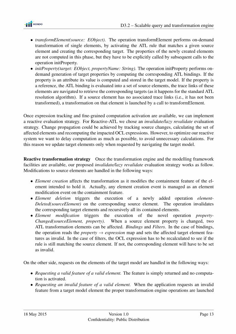
• transformElement(source: EObject). The operation transformElement performs on-demandtransformation of single elements, by activating the ATL rule that matches a given sourceelement and creating the corresponding target. The properties of the newly created elementsare not computed in this phase, but they have to be explicitly called by subsequent calls to theoperation initProperty.• initProperty(target: EObject, propertyName: String). The operation initProperty performs on-
demand generation of target properties by computing the corresponding ATL bindings. If theproperty is an attribute its value is computed and stored in the target model. If the property isa reference, the ATL binding is evaluated into a set of source elements, the trace links of theseelements are navigated to retrieve the corresponding targets (as it happens for the standard ATLresolution algorithm). If a source element has no associated trace links (i.e., it has not beentransformed), a transformation on that element is launched by a call to transformElement.
Once expression tracking and fine-grained computation activation are available, we can implementa reactive evaluation strategy. For Reactive-ATL we chose an invalidate/lazy revalidate evaluationstrategy. Change propagation could be achieved by tracking source changes, calculating the set ofaffected elements and recomputing the impacted OCL expressions. However, to optimize our reactivesystem we want to delay computation as much as possible, to avoid unnecessary calculations. Forthis reason we update target elements only when requested by navigating the target model.
Reactive transformation strategy Once the transformation engine and the modelling frameworkfacilities are available, our proposed invalidate/lazy revalidate evaluation strategy works as follow.Modifications to source elements are handled in the following ways:
• Element creation affects the transformation as it modifies the containment feature of the el-ement intended to hold it. Actually, any element creation event is managed as an elementmodification event on the containment feature.• Element deletion triggers the execution of a newly added operation element-
Deleted(sourceElement) on the corresponding source element. The operation invalidatesthe corresponding target elements and recursively all its contained elements.• Element modification triggers the execution of the novel operation property-
Changed(sourceElement, property). When a source element property is changed, twoATL transformation elements can be affected. Bindings and Filters. In the case of bindings,the operation reads the property → expression map and sets the affected target element fea-tures as invalid. In the case of filters, the OCL expression has to be recalculated to see if therule is still matching the source element. If not, the corresponding element will have to be setas invalid.
On the other side, requests on the elements of the target model are handled in the following ways:
• Requesting a valid feature of a valid element. The feature is simply returned and no computa-tion is activated.• Requesting an invalid feature of a valid element. When the application requests an invalid
feature from a target model element the proper transformation engine operations are launched
18 May 2015 Version 1.0Confidentiality: Public Distribution
Page 13
D3.2 – Scalable query and transformation engine
Application
Transformationsource code
Transformationengine
Reactivetarget model
write
notify
update
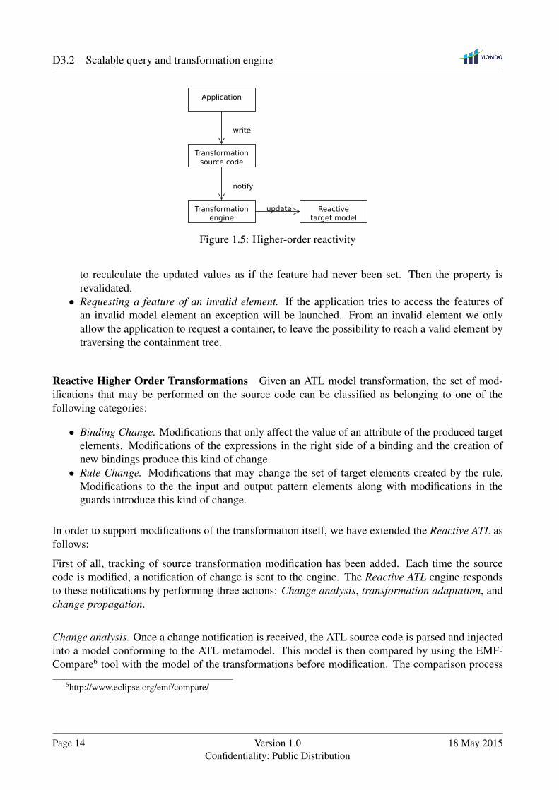
Figure 1.5: Higher-order reactivity
to recalculate the updated values as if the feature had never been set. Then the property isrevalidated.• Requesting a feature of an invalid element. If the application tries to access the features of
an invalid model element an exception will be launched. From an invalid element we onlyallow the application to request a container, to leave the possibility to reach a valid element bytraversing the containment tree.
Reactive Higher Order Transformations Given an ATL model transformation, the set of mod-ifications that may be performed on the source code can be classified as belonging to one of thefollowing categories:
• Binding Change. Modifications that only affect the value of an attribute of the produced targetelements. Modifications of the expressions in the right side of a binding and the creation ofnew bindings produce this kind of change.• Rule Change. Modifications that may change the set of target elements created by the rule.
Modifications to the the input and output pattern elements along with modifications in theguards introduce this kind of change.
In order to support modifications of the transformation itself, we have extended the Reactive ATL asfollows:
First of all, tracking of source transformation modification has been added. Each time the sourcecode is modified, a notification of change is sent to the engine. The Reactive ATL engine respondsto these notifications by performing three actions: Change analysis, transformation adaptation, andchange propagation.
Change analysis. Once a change notification is received, the ATL source code is parsed and injectedinto a model conforming to the ATL metamodel. This model is then compared by using the EMF-Compare6 tool with the model of the transformations before modification. The comparison process
6http://www.eclipse.org/emf/compare/
Page 14 Version 1.0Confidentiality: Public Distribution
18 May 2015
D3.2 – Scalable query and transformation engine
yields as a result a list of changes, classified as Binding or Rule changes.
Transformation adaptation. After detecting what have changed from one version of the transfor-mation to another, the running live transformation needs to be adapted so that new transformationoperations conform to the newer transformation specification.
Upon the initialization of any transformation, the ATL engine parses a compiled ATL transforma-tion (ASM code) and creates a map of operations (including those operations meant to transformelements and initialize bindings). These operations will be then called from the engine when neededduring the transformation process. Therefore, in order to make the engine use the specifications of anew transformation, this map of operations needs to be updated, so that it contains the modified ver-sion of the operations transforming elements and bindings. This goal is achieved by performing thefollowing steps: 1) the new transformation code is recompiled into ASM bytecode, 2) a new map ofoperations is calculated from the ASM code, 3) a hot replacement of the operations map is performed.
Change propagation. Once the running live transformation have been adapted to integrate thechanges introduced in the source code, a change propagation step is required in order to keep thetarget model consistent w.r.t. the transformation specification. The propagation operations dependon the kind of the transformation change to be propagated:
• Binding change propagation. A change on a binding is processed as follows: first, startingfrom the rule containing the modified binding, all model elements of the type of the targetmodel element holding the modified attribute are retrieved from the stored trace links. Noticethat this operation is not expensive, as the trace link set class stores maps allowing to retrievethe trace links produced by a given rule. Then, for each retrieved target model element, thefeature flag corresponding to the modified attribute is set to invalid.• Rule change propagation. A change affecting the set of elements a rule produce is more chal-
lenging to manage.As in the case of binding changes, trace links are used to retrieve affected target model elementsand, as it is a rule change, in this case it is the full element what is invalidated by setting itsvalidity flag to invalid. However, this processing is not enough as invalid elements may bereached by the application user while requesting target elements. In order to prevent this tohappen, we need to find target elements that reference elements of the type of the invalidatedtarget element and set their referencing feature to invalid, so that it is recalculated in the nextaccess. We achieve this objective by Cross-reference calculation on the metamodel. Given atarget metamodel type, we store the list of types holding references to it. Then, as a secondstep in the processing of a rule change we use trace links to find elements corresponding tothose types and set their feature flag to invalid.
1.4 Using Reactive Transformations
While the reactive system autonomously manages the computation, the user still keeps an indirectcontrol over the evaluation strategy by organizing the sequence of model updates and requests. In
18 May 2015 Version 1.0Confidentiality: Public Distribution
Page 15
D3.2 – Scalable query and transformation engine
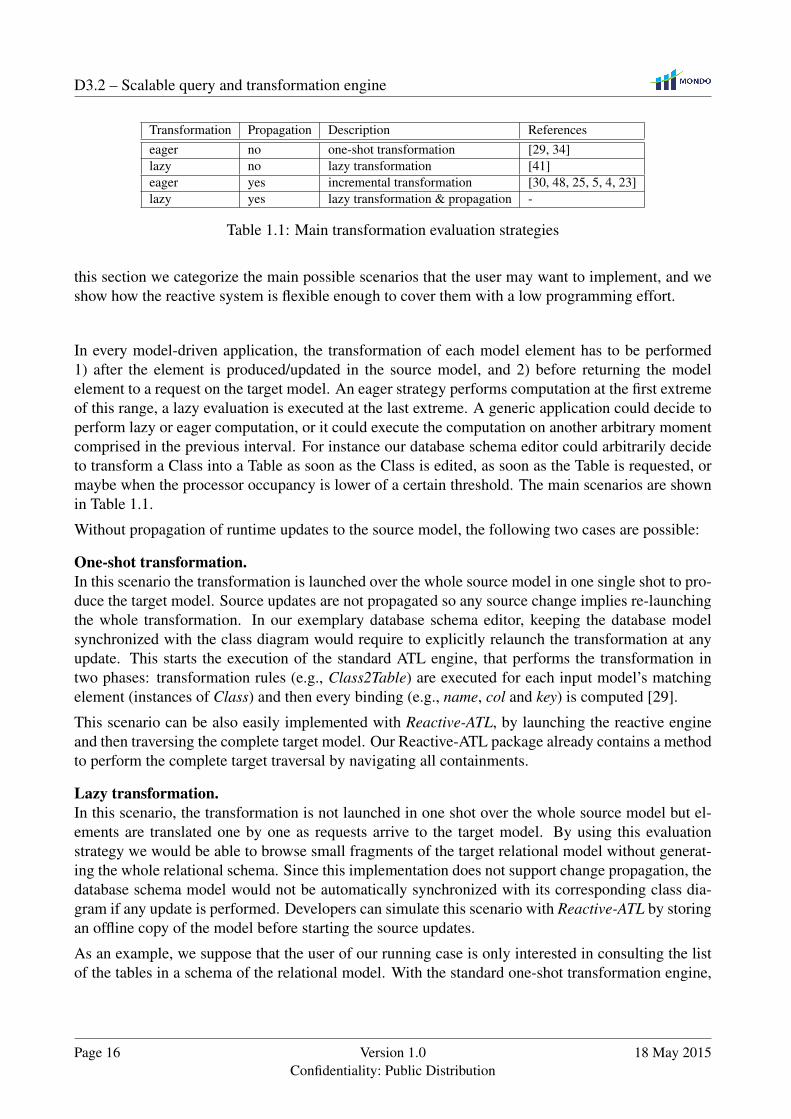
Transformation Propagation Description Referenceseager no one-shot transformation [29, 34]lazy no lazy transformation [41]eager yes incremental transformation [30, 48, 25, 5, 4, 23]lazy yes lazy transformation & propagation -
Table 1.1: Main transformation evaluation strategies
this section we categorize the main possible scenarios that the user may want to implement, and weshow how the reactive system is flexible enough to cover them with a low programming effort.
In every model-driven application, the transformation of each model element has to be performed1) after the element is produced/updated in the source model, and 2) before returning the modelelement to a request on the target model. An eager strategy performs computation at the first extremeof this range, a lazy evaluation is executed at the last extreme. A generic application could decide toperform lazy or eager computation, or it could execute the computation on another arbitrary momentcomprised in the previous interval. For instance our database schema editor could arbitrarily decideto transform a Class into a Table as soon as the Class is edited, as soon as the Table is requested, ormaybe when the processor occupancy is lower of a certain threshold. The main scenarios are shownin Table 1.1.
Without propagation of runtime updates to the source model, the following two cases are possible:
One-shot transformation.In this scenario the transformation is launched over the whole source model in one single shot to pro-duce the target model. Source updates are not propagated so any source change implies re-launchingthe whole transformation. In our exemplary database schema editor, keeping the database modelsynchronized with the class diagram would require to explicitly relaunch the transformation at anyupdate. This starts the execution of the standard ATL engine, that performs the transformation intwo phases: transformation rules (e.g., Class2Table) are executed for each input model’s matchingelement (instances of Class) and then every binding (e.g., name, col and key) is computed [29].
This scenario can be also easily implemented with Reactive-ATL, by launching the reactive engineand then traversing the complete target model. Our Reactive-ATL package already contains a methodto perform the complete target traversal by navigating all containments.
Lazy transformation.In this scenario, the transformation is not launched in one shot over the whole source model but el-ements are translated one by one as requests arrive to the target model. By using this evaluationstrategy we would be able to browse small fragments of the target relational model without generat-ing the whole relational schema. Since this implementation does not support change propagation, thedatabase schema model would not be automatically synchronized with its corresponding class dia-gram if any update is performed. Developers can simulate this scenario with Reactive-ATL by storingan offline copy of the model before starting the source updates.
As an example, we suppose that the user of our running case is only interested in consulting the listof the tables in a schema of the relational model. With the standard one-shot transformation engine,
Page 16 Version 1.0Confidentiality: Public Distribution
18 May 2015
D3.2 – Scalable query and transformation engine
the application has to generate the full relational model, including the tables from other schemas andall the attributes.
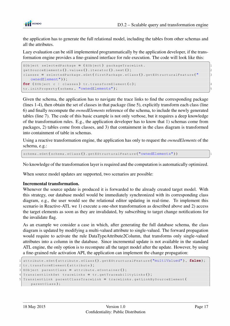
Lazy evaluation can be still implemented programmatically by the application developer, if the trans-formation engine provides a fine-grained interface for rule execution. The code will look like this:� �
1EObject selectedPackage = ( EObject ) packageTraceLink .2getSourceElements ( ) . values ( ) . iterator ( ) . next ( ) ;3classes = selectedPackage . eGet ( firstPackage . eClass ( ) . getEStructuralFeature ("
ownedElement" ) ) ;4for ( EObject c : classes ) tr . transformElement ( c ) ;5tr . initProperty ( schema , "ownedElements" ) ;� �
Given the schema, the application has to navigate the trace links to find the corresponding package(lines 1-4), then obtain the set of classes in that package (line 5), explicitly transform each class (line6) and finally recompute the ownedElements reference of the schema, to include the newly generatedtables (line 7). The code of this basic example is not only verbose, but it requires a deep knowledgeof the transformation rules. E.g., the application developer has to know that 1) schemas come frompackages, 2) tables come from classes, and 3) that containment in the class diagram is transformedinto containment of table in schemas.
Using a reactive transformation engine, the application has only to request the ownedElements of theschema, e.g.:� �
1schema . eGet ( schema . eClass ( ) . getEStructuralFeature ("ownedElements" ) )� �No knowledge of the transformation layer is required and the computation is automatically optimized.
When source model updates are supported, two scenarios are possible:
Incremental transformation.Whenever the source update is produced it is forwarded to the already created target model. Withthis strategy, our database model would be immediately synchronized with its corresponding classdiagram, e.g., the user would see the relational editor updating in real-time. To implement thisscenario in Reactive-ATL we 1) execute a one-shot transformation as described above and 2) accessthe target elements as soon as they are invalidated, by subscribing to target change notifications forthe invalidate flag.
As an example we consider a case in which, after generating the full database schema, the classdiagram is updated by modifying a multi-valued attribute to single-valued. The forward propagationwould require to activate the rule DataTypeAttribute2Column, that transforms only single-valuedattributes into a column in the database. Since incremental update is not available in the standardATL engine, the only option is to recompute all the target model after the update. However, by usinga fine-grained rule activation API, the application can implement the change propagation:� �
1 attribute . eSet ( attribute . eClass ( ) . getEStructuralFeature ("multiValued" ) , false ) ;2 tr . transformElement ( attribute ) ;3 EObject parentClass = attribute . eContainer ( ) ;4 TransientLinkSet traceLinks = tr . getTraceabilityLinks ( ) ;5 TransientLink parentClassTraceLink = traceLinks . getLinkBySourceElement (
parentClass ) ;
18 May 2015 Version 1.0Confidentiality: Public Distribution
Page 17
D3.2 – Scalable query and transformation engine
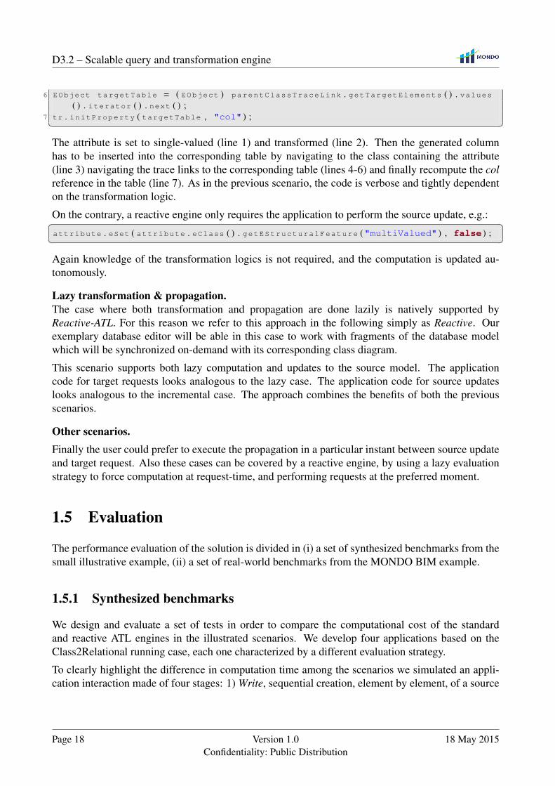
6 EObject targetTable = ( EObject ) parentClassTraceLink . getTargetElements ( ) . values( ) . iterator ( ) . next ( ) ;
7 tr . initProperty ( targetTable , "col" ) ;� �The attribute is set to single-valued (line 1) and transformed (line 2). Then the generated columnhas to be inserted into the corresponding table by navigating to the class containing the attribute(line 3) navigating the trace links to the corresponding table (lines 4-6) and finally recompute the colreference in the table (line 7). As in the previous scenario, the code is verbose and tightly dependenton the transformation logic.
On the contrary, a reactive engine only requires the application to perform the source update, e.g.:� �attribute . eSet ( attribute . eClass ( ) . getEStructuralFeature ("multiValued" ) , false ) ;� �Again knowledge of the transformation logics is not required, and the computation is updated au-tonomously.
Lazy transformation & propagation.The case where both transformation and propagation are done lazily is natively supported byReactive-ATL. For this reason we refer to this approach in the following simply as Reactive. Ourexemplary database editor will be able in this case to work with fragments of the database modelwhich will be synchronized on-demand with its corresponding class diagram.
This scenario supports both lazy computation and updates to the source model. The applicationcode for target requests looks analogous to the lazy case. The application code for source updateslooks analogous to the incremental case. The approach combines the benefits of both the previousscenarios.
Other scenarios.Finally the user could prefer to execute the propagation in a particular instant between source updateand target request. Also these cases can be covered by a reactive engine, by using a lazy evaluationstrategy to force computation at request-time, and performing requests at the preferred moment.
1.5 Evaluation
The performance evaluation of the solution is divided in (i) a set of synthesized benchmarks from thesmall illustrative example, (ii) a set of real-world benchmarks from the MONDO BIM example.
1.5.1 Synthesized benchmarks
We design and evaluate a set of tests in order to compare the computational cost of the standardand reactive ATL engines in the illustrated scenarios. We develop four applications based on theClass2Relational running case, each one characterized by a different evaluation strategy.
To clearly highlight the difference in computation time among the scenarios we simulated an appli-cation interaction made of four stages: 1) Write, sequential creation, element by element, of a source
Page 18 Version 1.0Confidentiality: Public Distribution
18 May 2015
D3.2 – Scalable query and transformation engine
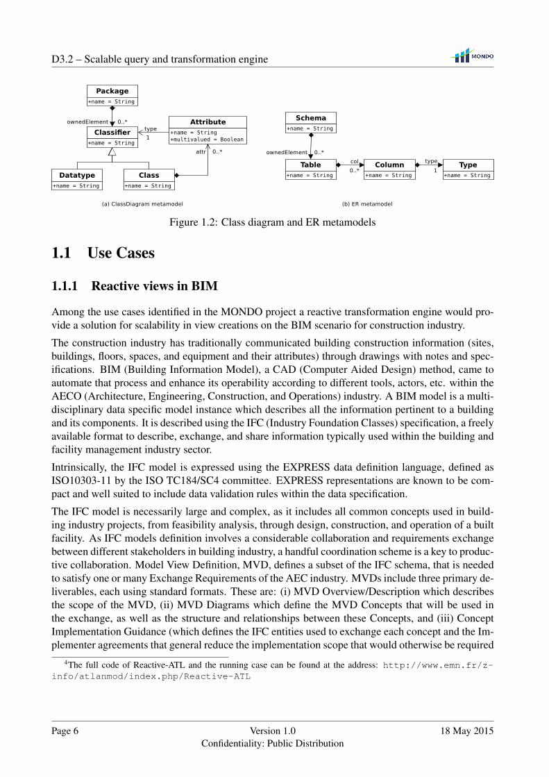
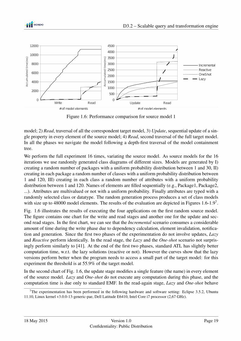
Figure 1.6: Performance comparison for source model 1
model; 2) Read, traversal of all the correspondent target model, 3) Update, sequential update of a sin-gle property in every element of the source model; 4) Read, second traversal of the full target model.In all the phases we navigate the model following a depth-first traversal of the model containmenttree.
We perform the full experiment 16 times, variating the source model. As source models for the 16iterations we use randomly generated class diagrams of different sizes. Models are generated by I)creating a random number of packages with a uniform probability distribution between 1 and 30, II)creating in each package a random number of classes with a uniform probability distribution between1 and 120, III) creating in each class a random number of attributes with a uniform probabilitydistribution between 1 and 120. Names of elements are filled sequentially (e.g., Package1, Package2,...). Attributes are multivalued or not with a uniform probability. Finally attributes are typed with arandomly selected class or datatype. The random generation process produces a set of class modelswith size up to 48000 model elements. The results of the evaluation are depicted in Figures 1.6-1.97.
Fig. 1.6 illustrates the results of executing the four applications on the first random source model.The figure contains one chart for the write and read stages and another one for the update and sec-ond read stages. In the first chart, we can see that the Incremental scenario consumes a considerableamount of time during the write phase due to dependency calculation, element invalidation, notifica-tion and generation. Since the first two phases of the experimentation do not involve updates, Lazyand Reactive perform identically. In the read stage, the Lazy and the One-shot scenario not surpris-ingly perform similarly to [41]. At the end of the first two phases, standard ATL has slightly bettercomputation time, w.r.t. the lazy solutions (reactive or not). However the curves show that the lazyversions perform better when the program needs to access a small part of the target model: for thisexperiment the threshold is at 55.9% of the target model.
In the second chart of Fig. 1.6, the update stage modifies a single feature (the name) in every elementof the source model. Lazy and One-shot do not execute any computation during this phase, and thecomputation time is due only to standard EMF. In the read-again stage, Lazy and One-shot behave
7The experimentation has been performed in the following hardware and software setting: Eclipse 3.5.2, Ubuntu11.10, Linux kernel v3.0.0-13-generic-pae, Dell Latitude E6410, Intel Core i7 processor (2,67 GHz).
18 May 2015 Version 1.0Confidentiality: Public Distribution
Page 19
D3.2 – Scalable query and transformation engineSheet1
Page 1
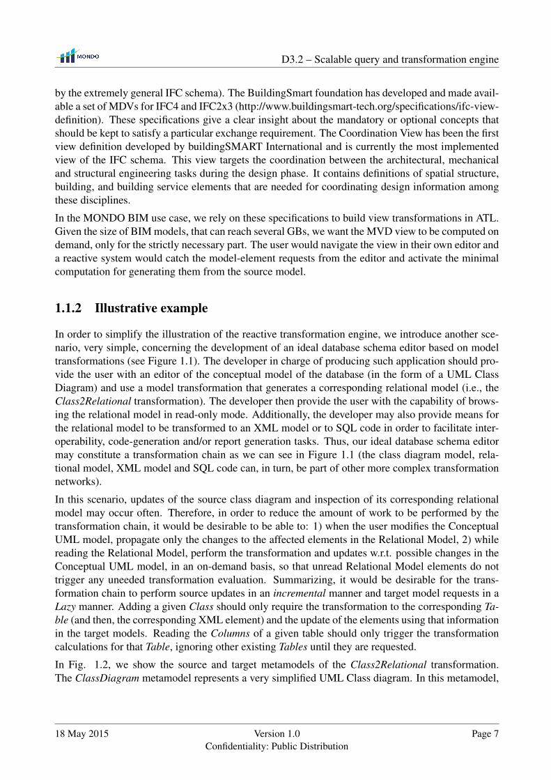
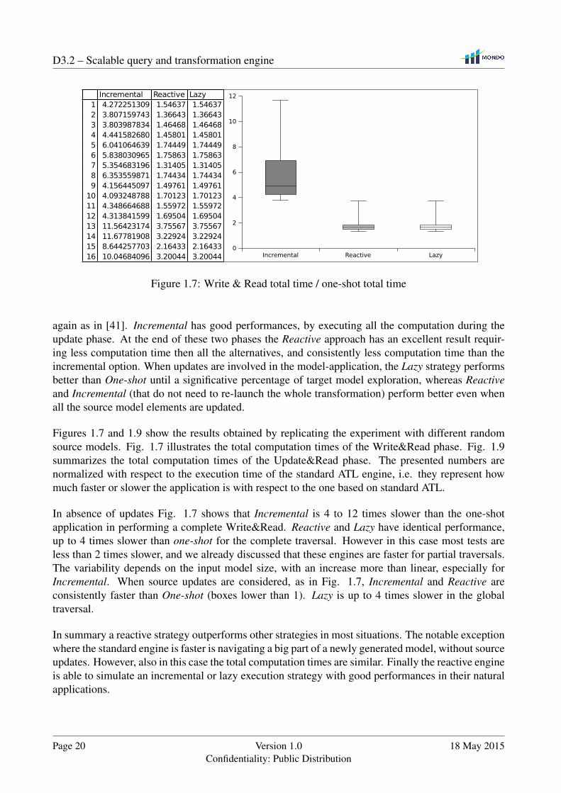
Incremental Reactive Lazy1 4.272251309 1.54637 1.546372 3.807159743 1.36643 1.366433 3.803987834 1.46468 1.464684 4.441582680 1.45801 1.458015 6.041064639 1.74449 1.744496 5.838030965 1.75863 1.758637 5.354683196 1.31405 1.314058 6.353559871 1.74434 1.744349 4.156445097 1.49761 1.4976110 4.093248788 1.70123 1.7012311 4.348664688 1.55972 1.5597212 4.313841599 1.69504 1.6950413 11.56423174 3.75567 3.7556714 11.67781908 3.22924 3.2292415 8.644257703 2.16433 2.1643316 10.04684096 3.20044 3.20044 Incremental Reactive Lazy
0
2
4
6
8
10
12
Figure 1.7: Write & Read total time / one-shot total time
again as in [41]. Incremental has good performances, by executing all the computation during theupdate phase. At the end of these two phases the Reactive approach has an excellent result requir-ing less computation time then all the alternatives, and consistently less computation time than theincremental option. When updates are involved in the model-application, the Lazy strategy performsbetter than One-shot until a significative percentage of target model exploration, whereas Reactiveand Incremental (that do not need to re-launch the whole transformation) perform better even whenall the source model elements are updated.
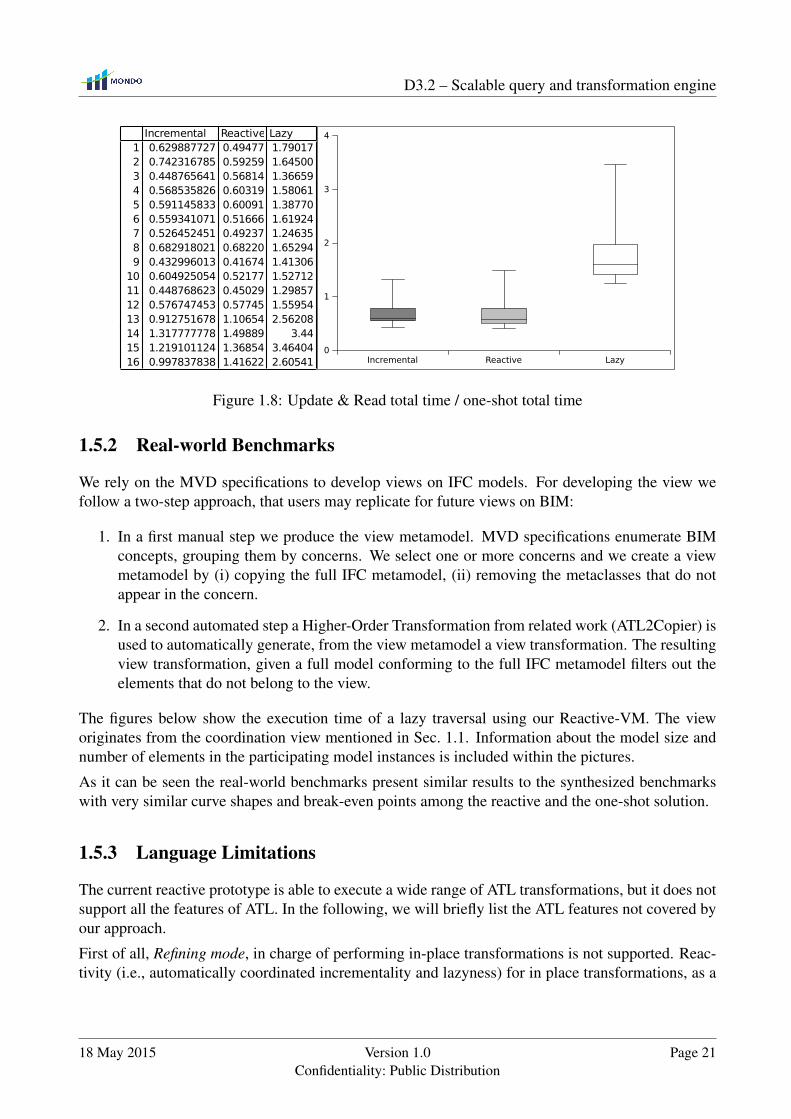
Figures 1.7 and 1.9 show the results obtained by replicating the experiment with different randomsource models. Fig. 1.7 illustrates the total computation times of the Write&Read phase. Fig. 1.9summarizes the total computation times of the Update&Read phase. The presented numbers arenormalized with respect to the execution time of the standard ATL engine, i.e. they represent howmuch faster or slower the application is with respect to the one based on standard ATL.
In absence of updates Fig. 1.7 shows that Incremental is 4 to 12 times slower than the one-shotapplication in performing a complete Write&Read. Reactive and Lazy have identical performance,up to 4 times slower than one-shot for the complete traversal. However in this case most tests areless than 2 times slower, and we already discussed that these engines are faster for partial traversals.The variability depends on the input model size, with an increase more than linear, especially forIncremental. When source updates are considered, as in Fig. 1.7, Incremental and Reactive areconsistently faster than One-shot (boxes lower than 1). Lazy is up to 4 times slower in the globaltraversal.
In summary a reactive strategy outperforms other strategies in most situations. The notable exceptionwhere the standard engine is faster is navigating a big part of a newly generated model, without sourceupdates. However, also in this case the total computation times are similar. Finally the reactive engineis able to simulate an incremental or lazy execution strategy with good performances in their naturalapplications.
Page 20 Version 1.0Confidentiality: Public Distribution
18 May 2015
D3.2 – Scalable query and transformation engineSheet1
Page 1
Incremental Reactive Lazy1 0.629887727 0.49477 1.790172 0.742316785 0.59259 1.645003 0.448765641 0.56814 1.366594 0.568535826 0.60319 1.580615 0.591145833 0.60091 1.387706 0.559341071 0.51666 1.619247 0.526452451 0.49237 1.246358 0.682918021 0.68220 1.652949 0.432996013 0.41674 1.4130610 0.604925054 0.52177 1.5271211 0.448768623 0.45029 1.2985712 0.576747453 0.57745 1.5595413 0.912751678 1.10654 2.5620814 1.317777778 1.49889 3.4415 1.219101124 1.36854 3.4640416 0.997837838 1.41622 2.60541 Incremental Reactive Lazy
0
1
2
3
4
Figure 1.8: Update & Read total time / one-shot total time
1.5.2 Real-world Benchmarks
We rely on the MVD specifications to develop views on IFC models. For developing the view wefollow a two-step approach, that users may replicate for future views on BIM:
1. In a first manual step we produce the view metamodel. MVD specifications enumerate BIMconcepts, grouping them by concerns. We select one or more concerns and we create a viewmetamodel by (i) copying the full IFC metamodel, (ii) removing the metaclasses that do notappear in the concern.
2. In a second automated step a Higher-Order Transformation from related work (ATL2Copier) isused to automatically generate, from the view metamodel a view transformation. The resultingview transformation, given a full model conforming to the full IFC metamodel filters out theelements that do not belong to the view.
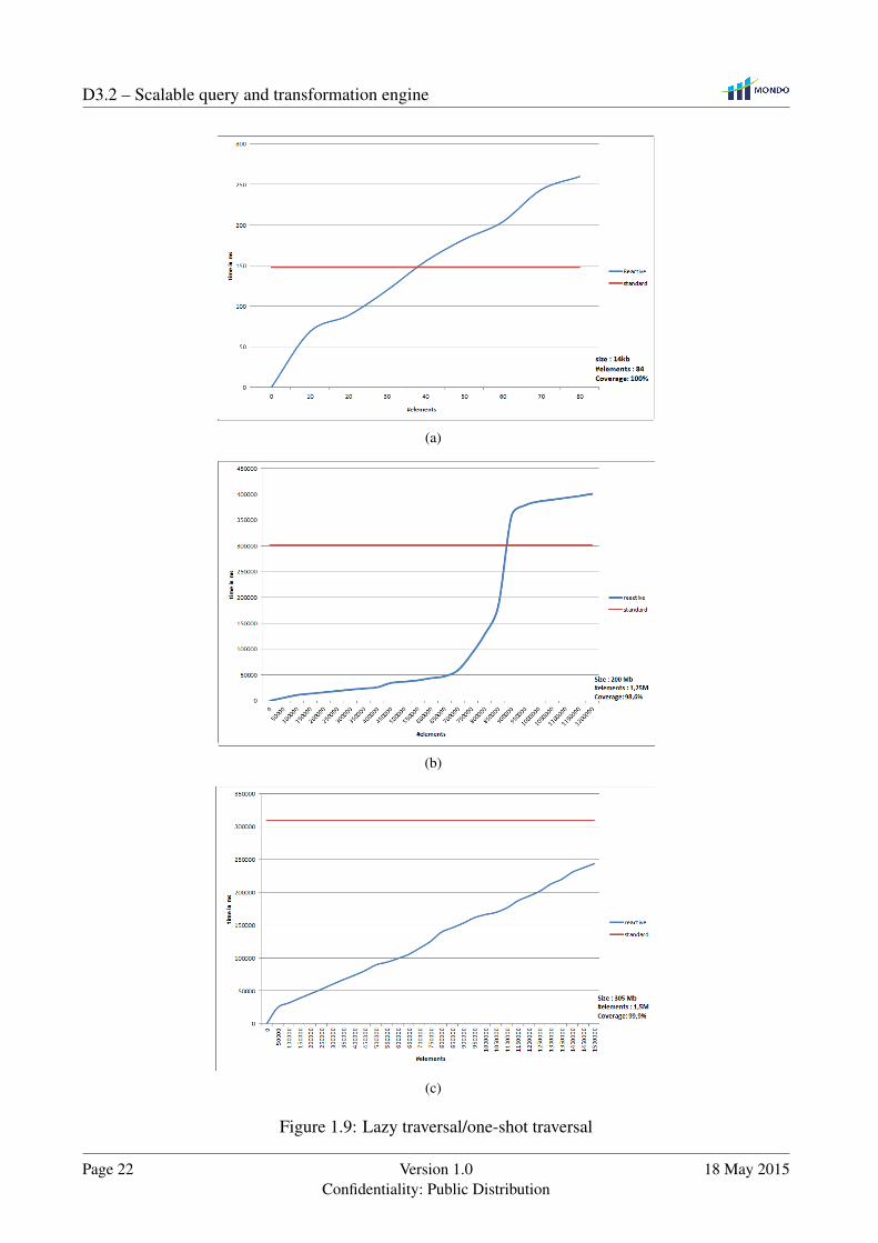
The figures below show the execution time of a lazy traversal using our Reactive-VM. The vieworiginates from the coordination view mentioned in Sec. 1.1. Information about the model size andnumber of elements in the participating model instances is included within the pictures.
As it can be seen the real-world benchmarks present similar results to the synthesized benchmarkswith very similar curve shapes and break-even points among the reactive and the one-shot solution.
1.5.3 Language Limitations
The current reactive prototype is able to execute a wide range of ATL transformations, but it does notsupport all the features of ATL. In the following, we will briefly list the ATL features not covered byour approach.
First of all, Refining mode, in charge of performing in-place transformations is not supported. Reac-tivity (i.e., automatically coordinated incrementality and lazyness) for in place transformations, as a
18 May 2015 Version 1.0Confidentiality: Public Distribution
Page 21
D3.2 – Scalable query and transformation engine
(a)
(b)
(c)
Figure 1.9: Lazy traversal/one-shot traversal
Page 22 Version 1.0Confidentiality: Public Distribution
18 May 2015

D3.2 – Scalable query and transformation engine
very specific case of model transformation, constitutes a research subject on ist own. Nevertheless,note that in place transformations can be simulated by just creating a normal ATL transformation thatcopies the input model to an output model conforming to the same metamodel, what is supported byour prototype.
Secondly, the imperative constructs, i.e., Called rules and do patterns in rules lay out of the scopeof the present deliverable. Reactivity in imperative languages have been largely studied and thus, theresults in literature may be integrated to our approach. Moreover, the preferred style while writingATL transformation is the declarative one, leaving the use of imperative constructs to only specificproblems that are too difficult to solve following a declarative style.
Finally, for simplicity, some standard ATL stataments are currently not supported. The list of non-supported statements is as follows:
• Metamodel specific operations (refInvokeOperation())• Helpers• Rule Variables• Rule Inheritance• Multiple Source Elements• Reflection (operations like refInmmediateComposite())• Resolution of specific target elements (resolveTemp())• allInstances()
Note however that, unlike Refining mode and the imperative statements, that would require chang-ing/adapting the approaches used for providing incrementality and lazy evaluation, all other state-ments could be handled by just extending our prototype to support them.
1.5.4 Prototype framework limitations
Our reactive prototipe can be used to efficiently handle the development of many application con-texts. However, there are some limitations (or possible extensions) that may be integrated in order toincrease the range of supported scenarios.
Target model edition. As for now, our reactive engine allows edition only in the source model,while the target model is read-only. This applies also for models participating in a chain, where themiddle models gets modified only by the updates of the source model and not direcly by the directediting of users or developers. It would be interesting to provide support for the direct editing ofthe target model. This will require to propage the changes to the sources models, thus, requiringbidirectionality.
Transactions. The granularity of changes or request supported by reactive ATL is at the level ofmodel element or model element property. For some scenarios, it would be interesting to record a setof changes in a transaction, so that they can be safely applied (or rolled back) all together.
18 May 2015 Version 1.0Confidentiality: Public Distribution
Page 23
Chapter 2
VIATRA3-CEP:Streaming Model Transformations ByComplex Event Processing
Scalability of models, queries and transformations is a key challenge in model-driven engineeringto handle complex industrial domains such as automotive, avionics, cyber-physical systems or ubiq-uitous computing. The maintenance and manipulation of large models identifies unique scenariosaddressed by a novel class of model transformations (MT) to overcome the limitations or extend thecapabilities of traditional (batch or incremental) MT approaches.
Change-driven transformations [6] consume or produce changes of source and target models as theirinput or output models to enable transformations over partially materialized models and to reducetraceability information. Streaming transformations are defined [37] as a “special kind of transfor-mation in which the whole input model is not completely available at the beginning of the transfor-mation, but it is continuously generated.“ An additional class of streaming transformations aims totackle huge models by feeding a transformation process incrementally (keeping only a part of themodel in memory at any time).
In the current report, we identify and address a novel class of streaming transformations for livemodels where the models themselves are not necessarily huge or infinite, but they change or evolve ata very fast rate (for instance, 25 times per second), and it is the stream of model changes that requiresefficient processing. We propose a novel technique for streaming transformations to process theseevent streams in order to identify a complex series of events and then execute model transformationsover them in a reactive way.
Our contribution includes a domain-specific event processing language for defining atomic eventsclasses (from elementary or compound model changes using change patterns [6]) and combiningthese events into complex patterns of events. We also propose a general, model-based complexevent processing architecture with a prototype engine VIATRA-CEP to process rapidly evolvingevent streams. We also include an initial scalability assessment of the framework on a live modeltransformation scenario.
24
D3.2 – Scalable query and transformation engine
Our approach keeps the advantages of change-driven transformation as models can be partially ma-terialized, since the processed event stream carries over only few relevant contextual model elementsbut not the models themselves. Instead, incremental model queries observe the model and publishrelevant structural changes as atomic events in an event stream. Then this stream is processed byintegrating known techniques from complex event processing (CEP) [31] to identify and handle acomplex series of events.
In the rest of the chapter, in Section 2.1, we introduce a case study of gesture recognition over livemodels used as a running example. The core ideas of our approach are presented in Section 2.2 whileSection 2.3 presents an integrated tool set as a proof-of-concept. We carry out an initial performanceof the approach in Section 2.4.
2.1 Case study: gesture recognition by live models
Our approach will be demonstrated on a gesture recognition case study. The use case is based on ourpreliminary work [19], presented earlier at EclipseCon Europe 2012, but without using the frameworkdescribed in this report.
In the case study, a human body is observed by optical sensors. The stream of data from the sensors(Microsoft KINECT [32] in our case) carries the spatial position of the hands, wrists, knees, etc. Thisstream is continuously processed and its data is stored in a live model, technically, an EMF modelmaintained via a Java based API [26]. Every time the optical sensors capture a new frame, the modelis updated with the appropriate spatial data. The sensors process 25 frames per second, resulting in25 model update transactions each second. The complexity of the scenario arises from the frequentchanges the model undergoes. Executing model transformations on such a model poses several prob-lems, since it would become obsolete quickly after being loaded into the memory. Moreover, modelupdate transactions affect multiple model elements.
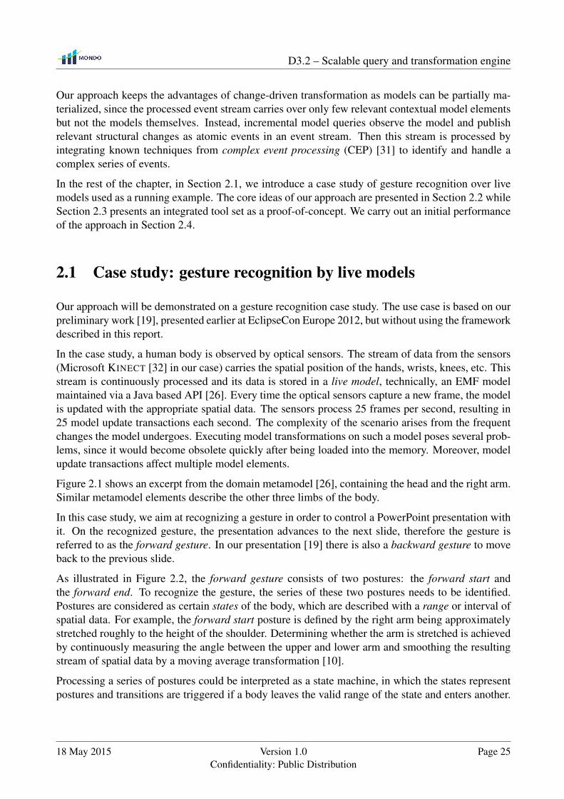
Figure 2.1 shows an excerpt from the domain metamodel [26], containing the head and the right arm.Similar metamodel elements describe the other three limbs of the body.
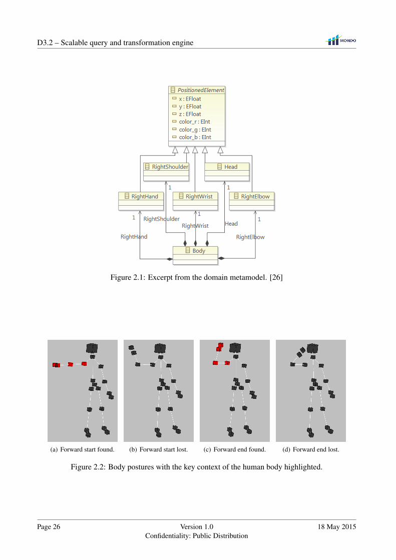
In this case study, we aim at recognizing a gesture in order to control a PowerPoint presentation withit. On the recognized gesture, the presentation advances to the next slide, therefore the gesture isreferred to as the forward gesture. In our presentation [19] there is also a backward gesture to moveback to the previous slide.
As illustrated in Figure 2.2, the forward gesture consists of two postures: the forward start andthe forward end. To recognize the gesture, the series of these two postures needs to be identified.Postures are considered as certain states of the body, which are described with a range or interval ofspatial data. For example, the forward start posture is defined by the right arm being approximatelystretched roughly to the height of the shoulder. Determining whether the arm is stretched is achievedby continuously measuring the angle between the upper and lower arm and smoothing the resultingstream of spatial data by a moving average transformation [10].
Processing a series of postures could be interpreted as a state machine, in which the states representpostures and transitions are triggered if a body leaves the valid range of the state and enters another.
18 May 2015 Version 1.0Confidentiality: Public Distribution
Page 25
D3.2 – Scalable query and transformation engine
Figure 2.1: Excerpt from the domain metamodel. [26]
(a) Forward start found. (b) Forward start lost. (c) Forward end found. (d) Forward end lost.
Figure 2.2: Body postures with the key context of the human body highlighted.
Page 26 Version 1.0Confidentiality: Public Distribution
18 May 2015
D3.2 – Scalable query and transformation engine
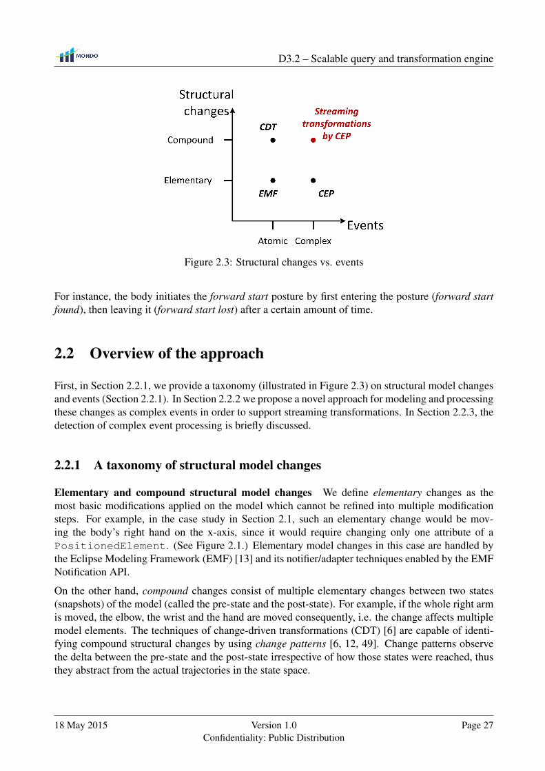
Figure 2.3: Structural changes vs. events
For instance, the body initiates the forward start posture by first entering the posture (forward startfound), then leaving it (forward start lost) after a certain amount of time.
2.2 Overview of the approach
First, in Section 2.2.1, we provide a taxonomy (illustrated in Figure 2.3) on structural model changesand events (Section 2.2.1). In Section 2.2.2 we propose a novel approach for modeling and processingthese changes as complex events in order to support streaming transformations. In Section 2.2.3, thedetection of complex event processing is briefly discussed.
2.2.1 A taxonomy of structural model changes
Elementary and compound structural model changes We define elementary changes as themost basic modifications applied on the model which cannot be refined into multiple modificationsteps. For example, in the case study in Section 2.1, such an elementary change would be mov-ing the body’s right hand on the x-axis, since it would require changing only one attribute of aPositionedElement. (See Figure 2.1.) Elementary model changes in this case are handled bythe Eclipse Modeling Framework (EMF) [13] and its notifier/adapter techniques enabled by the EMFNotification API.
On the other hand, compound changes consist of multiple elementary changes between two states(snapshots) of the model (called the pre-state and the post-state). For example, if the whole right armis moved, the elbow, the wrist and the hand are moved consequently, i.e. the change affects multiplemodel elements. The techniques of change-driven transformations (CDT) [6] are capable of identi-fying compound structural changes by using change patterns [6, 12, 49]. Change patterns observethe delta between the pre-state and the post-state irrespective of how those states were reached, thusthey abstract from the actual trajectories in the state space.
18 May 2015 Version 1.0Confidentiality: Public Distribution
Page 27

D3.2 – Scalable query and transformation engine
Atomic and complex events In our work, we consider both atomic and compound structuralchanges as atomic events in the event stream. This setup allows the use of events of different granu-larity. An atomic event is specified by its type, a set of model elements passed as parameters and atimestamp. Complex events are built up from sequences of atomic events and other complex events,using operators of an event algebra. Common operators enable the definition of events followingother events, mutually prohibited events, or events occurring within a given time window.
Complex event processing (CEP) [31] techniques provide guidance on how to evaluate the streamof atomic events in order to detect complex events. Unfortunately, most CEP tools do not integratewell with existing model management frameworks (like EMF) and significant programming effort isrequired to translate elementary and compound structural model changes originating from a modelingtool into event types appropriate for a CEP engine.
In our work, we aim at combining the benefits of CDT and CEP resulting in a novel technique foridentifying arbitrarily complex change events of compound structural changes.
2.2.2 Changes, events and streaming transformations
In this section, we demonstrate how streaming transformations can be defined by building upon well-established model query and transformation languages by elaborating the case study of Section 2.1.First, model queries will be used to identify the current state of the model and automatically publishnotifications on relevant state changes in the form of atomic events. Then these atomic events will becombined into complex events using operators of an event algebra. Finally, we define transformationrules that are activated by a complex event.
Model queries for structural constraints
Model queries capture structural constraints of a model. In this report, we employ the graph patternlanguage IQPL used by EMF-INCQUERY [42]. This choice is motivated by the high expressivenessof the language and the incremental query evaluation strategy of EMF-INCQUERY, which allows thesending of notifications upon the change of the result set of queries.
Listing 2.1 presents the graph pattern depicting the Forward start posture, as presented in Fig-ure 2.2(a). The pattern is parameterized with the spatial data of the right arm (consisting of theright hand, the right elbow and the right shoulder); the head; and the body the previous parts belongto. Accordingly, joins over the model are defined to describe this relationship in Lines 8-11. The For-ward start posture requires a stretched right arm to be detected, but the arm shall not be held higherthan head level (see Lines 13-14 and 16-17, respectively).
The latter one is a negative pattern call, which prohibits the occurrence of therightHandAboveHead pattern presented in Listing 2.2. The pattern compares the spatialcoordinates of the right hand and the head by their y coordinate. In Lines 8-9, the y coordinate of theright hand and the head is bound to the RHy and Hy variables, respectively. The variables are eval-uated in a check block in Lines 11-18 by invoking a Java based MovingAverageCalculatorusing Xbase syntax [20]. The details of the rightHandAboveHead pattern are omitted for spaceconsideration.
Page 28 Version 1.0Confidentiality: Public Distribution
18 May 2015
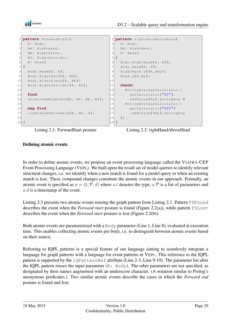
D3.2 – Scalable query and transformation engine
� �1 pattern ForwardStart (2 B : Body ,3 RH : RightHand ,4 RE : RightElbow ,5 RS : RightShoulder ,6 H : Head )7 {8 Body . Head ( B , H ) ;9 Body . RightHand ( B , RH ) ;10 Body . RightElbow ( B , RE ) ;11 Body . RightShoulder ( B , RS ) ;12
13 find14 stretchedRightArm ( B , RH , RE , RS ) ;15
16 neg find17 rightHandAboveHead ( B , RH , H ) ;18
19 }� �Listing 2.1: ForwardStart posture
� �1 pattern rightHandAboveHead (2 B : Body ,3 RH : RightHand ,4 H : Head )5 {6 Body . RightHand ( B , RH ) ;7 Body . Head ( B , H ) ;8 RightHand . y ( RH , RHy ) ;9 Head . y ( H , Hy ) ;10
11 check (12 MovingAverageCalculator : :13 getCalculator ("HY" ) .14 addValue ( Hy ) . movingAvg <15 MovingAverageCalculator : :16 getCalculator ("RHY" )17 . addValue ( RHy ) . movingAvg18 ) ;19 }� �
Listing 2.2: rightHandAboveHead
Defining atomic events
In order to define atomic events, we propose an event processing language called the VIATRA-CEPEvent Processing Language (VEPL). We built upon the result set of model queries to identify relevantstructural changes, i.e. we identify when a new match is found for a model query or when an existingmatch is lost. These compound changes constitute the atomic events in our approach. Formally, anatomic event is specified as a = (t,P , d) where a.t denotes the type, a.P is a list of parameters anda.d is a timestamp of the event.
Listing 2.3 presents two atomic events reusing the graph pattern from Listing 2.1. Pattern FSFounddescribes the event when the Forward start posture is found (Figure 2.2(a)), while pattern FSLostdescribes the event when the Forward start posture is lost (Figure 2.2(b)).
Both atomic events are parameterized with a Body parameter (Line 1, Line 8), evaluated at executiontime. This enables collecting atomic events per body, i.e. to distinguish between atomic events basedon their source.
Referring to IQPL patterns is a special feature of our language aiming to seamlessly integrate alanguage for graph patterns with a language for event patterns in VEPL. This reference to the IQPLpattern is supported by the iqPatternRef attribute (Line 2-3, Line 9-10). The parameter list afterthe IQPL pattern reuses the input parameter (B: Body). The other parameters are not specified, asdesignated by their names augmented with an underscore character. (A notation similar to Prolog’sanonymous predicates.) Two similar atomic events describe the cases in which the Forward endposture is found and lost.
18 May 2015 Version 1.0Confidentiality: Public Distribution
Page 29
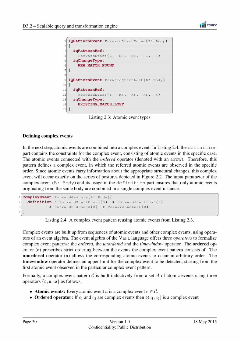
D3.2 – Scalable query and transformation engine
� �1 IQPatternEvent ForwardStartFound ( B : Body )2 {3 iqPatternRef :4 ForwardStart ( B , _RH , _RE , _RS , _H )5 iqChangeType :6 NEW_MATCH_FOUND7 }8
9 IQPatternEvent ForwardStartLost ( B : Body )10 {11 iqPatternRef :12 ForwardStart ( B , _RH , _RE , _RS , _H )13 iqChangeType :14 EXISTING_MATCH_LOST15 }� �
Listing 2.3: Atomic event types
Defining complex events
In the next step, atomic events are combined into a complex event. In Listing 2.4, the definitionpart contains the constraints for the complex event, consisting of atomic events in this specific case.The atomic events connected with the ordered operator (denoted with an arrow). Therefore, thispattern defines a complex event, in which the referred atomic events are observed in the specificorder. Since atomic events carry information about the appropriate structural changes, this complexevent will occur exactly on the series of postures depicted in Figure 2.2. The input parameter of thecomplex event (B: Body) and its usage in the definition part ensures that only atomic eventsoriginating from the same body are combined in a single complex event instance.� �
1 ComplexEvent ForwardGesture ( B : Body ) {2 definition : ForwardStartFound ( B ) -> ForwardStartLost ( B )3 -> ForwardEndFound ( B ) -> ForwardEndLost ( B )4 }� �
Listing 2.4: A complex event pattern reusing atomic events from Listing 2.3.
Complex events are built up from sequences of atomic events and other complex events, using opera-tors of an event algebra. The event algebra of the VEPL language offers three operators to formalizecomplex event patterns: the ordered, the unordered and the timewindow operator. The ordered op-erator (o) prescribes strict ordering between the events the complex event pattern consists of. Theunordered operator (u) allows the corresponding atomic events to occur in arbitrary order. Thetimewindow operator defines an upper limit for the complex event to be detected, starting from thefirst atomic event observed in the particular complex event pattern.
Formally, a complex event pattern C is built inductively from a set A of atomic events using threeoperators {o, u,w} as follows:
• Atomic events: Every atomic event a is a complex event e ∈ C.• Ordered operator: If c1 and c2 are complex events then o(c1, c2) is a complex event
Page 30 Version 1.0Confidentiality: Public Distribution
18 May 2015
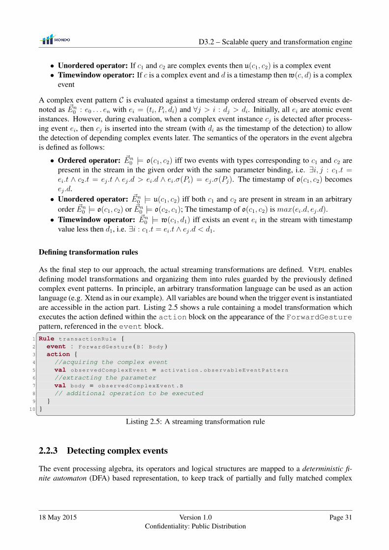
D3.2 – Scalable query and transformation engine
• Unordered operator: If c1 and c2 are complex events then u(c1, c2) is a complex event• Timewindow operator: If c is a complex event and d is a timestamp then w(c, d) is a complex
event
A complex event pattern C is evaluated against a timestamp ordered stream of observed events de-noted as ~En
0 : e0 . . . en with ei = (ti, Pi, di) and ∀j > i : dj > di. Initially, all ei are atomic eventinstances. However, during evaluation, when a complex event instance cj is detected after process-ing event ei, then cj is inserted into the stream (with di as the timestamp of the detection) to allowthe detection of depending complex events later. The semantics of the operators in the event algebrais defined as follows:
• Ordered operator: ~En0 |= o(c1, c2) iff two events with types corresponding to c1 and c2 are
present in the stream in the given order with the same parameter binding, i.e. ∃i, j : c1.t =ei.t ∧ c2.t = ej.t ∧ ej.d > ei.d ∧ ei.σ(Pi) = ej.σ(Pj). The timestamp of o(c1, c2) becomesej.d.• Unordered operator: ~En
0 |= u(c1, c2) iff both c1 and c2 are present in stream in an arbitraryorder ~En
0 |= o(c1, c2) or ~En0 |= o(c2, c1); The timestamp of o(c1, c2) is max(ei.d, ej.d).
• Timewindow operator: ~En0 |= w(c1, d1) iff exists an event ei in the stream with timestamp
value less then d1, i.e. ∃i : c1.t = ei.t ∧ ej.d < d1.
Defining transformation rules
As the final step to our approach, the actual streaming transformations are defined. VEPL enablesdefining model transformations and organizing them into rules guarded by the previously definedcomplex event patterns. In principle, an arbitrary transformation language can be used as an actionlanguage (e.g. Xtend as in our example). All variables are bound when the trigger event is instantiatedare accessible in the action part. Listing 2.5 shows a rule containing a model transformation whichexecutes the action defined within the action block on the appearance of the ForwardGesturepattern, referenced in the event block.� �
1 Rule transactionRule {2 event : ForwardGesture ( B : Body )3 action {4 //acquiring the complex event5 val observedComplexEvent = activation . observableEventPattern6 //extracting the parameter7 val body = observedComplexEvent . B8 // additional operation to be executed9 }10 }� �
Listing 2.5: A streaming transformation rule
2.2.3 Detecting complex events
The event processing algebra, its operators and logical structures are mapped to a deterministic fi-nite automaton (DFA) based representation, to keep track of partially and fully matched complex
18 May 2015 Version 1.0Confidentiality: Public Distribution
Page 31
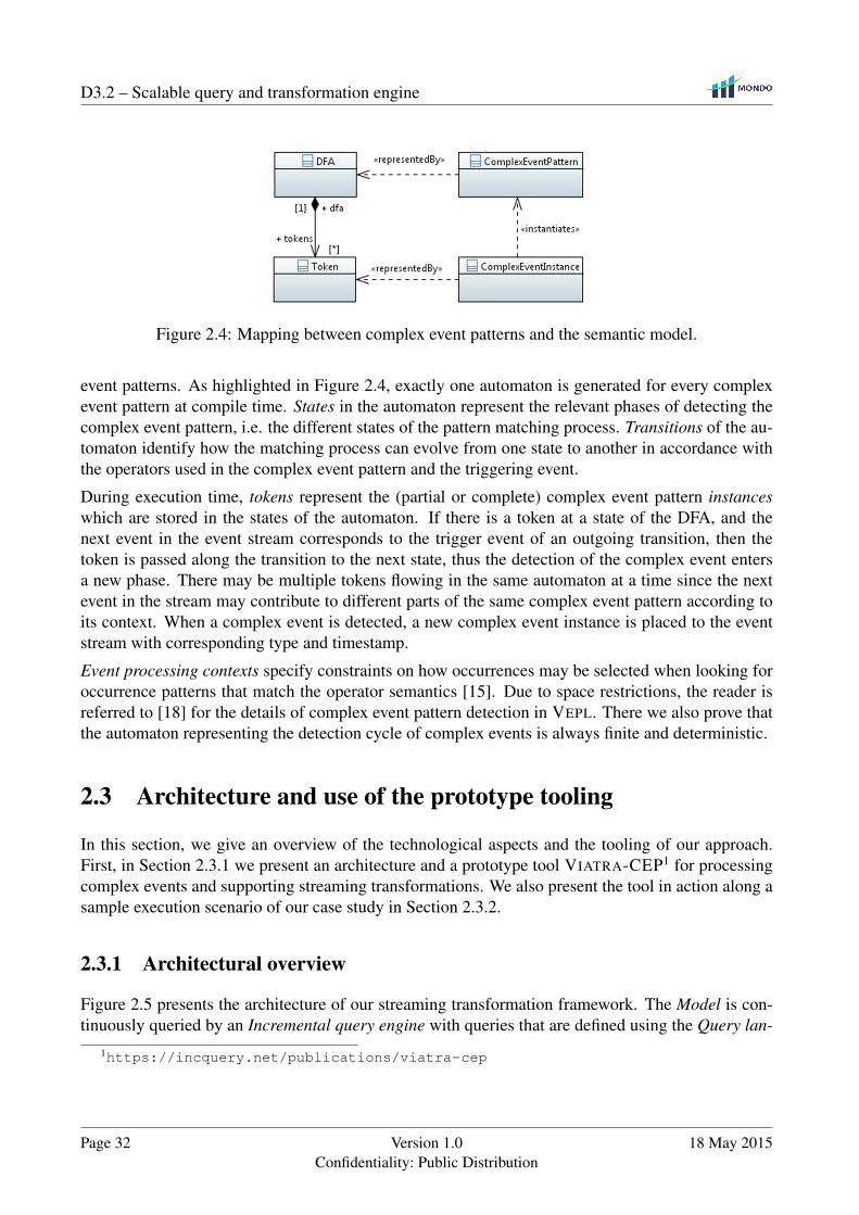
D3.2 – Scalable query and transformation engine
Figure 2.4: Mapping between complex event patterns and the semantic model.
event patterns. As highlighted in Figure 2.4, exactly one automaton is generated for every complexevent pattern at compile time. States in the automaton represent the relevant phases of detecting thecomplex event pattern, i.e. the different states of the pattern matching process. Transitions of the au-tomaton identify how the matching process can evolve from one state to another in accordance withthe operators used in the complex event pattern and the triggering event.
During execution time, tokens represent the (partial or complete) complex event pattern instanceswhich are stored in the states of the automaton. If there is a token at a state of the DFA, and thenext event in the event stream corresponds to the trigger event of an outgoing transition, then thetoken is passed along the transition to the next state, thus the detection of the complex event entersa new phase. There may be multiple tokens flowing in the same automaton at a time since the nextevent in the stream may contribute to different parts of the same complex event pattern according toits context. When a complex event is detected, a new complex event instance is placed to the eventstream with corresponding type and timestamp.
Event processing contexts specify constraints on how occurrences may be selected when looking foroccurrence patterns that match the operator semantics [15]. Due to space restrictions, the reader isreferred to [18] for the details of complex event pattern detection in VEPL. There we also prove thatthe automaton representing the detection cycle of complex events is always finite and deterministic.
2.3 Architecture and use of the prototype tooling
In this section, we give an overview of the technological aspects and the tooling of our approach.First, in Section 2.3.1 we present an architecture and a prototype tool VIATRA-CEP1 for processingcomplex events and supporting streaming transformations. We also present the tool in action along asample execution scenario of our case study in Section 2.3.2.
2.3.1 Architectural overview
Figure 2.5 presents the architecture of our streaming transformation framework. The Model is con-tinuously queried by an Incremental query engine with queries that are defined using the Query lan-
1https://incquery.net/publications/viatra-cep
Page 32 Version 1.0Confidentiality: Public Distribution
18 May 2015
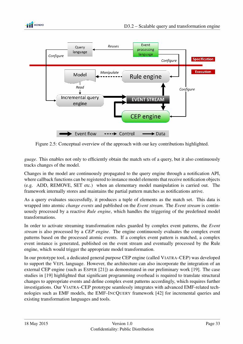
D3.2 – Scalable query and transformation engine
Figure 2.5: Conceptual overview of the approach with our key contributions highlighted.
guage. This enables not only to efficiently obtain the match sets of a query, but it also continuouslytracks changes of the model.
Changes in the model are continuously propagated to the query engine through a notification API,where callback functions can be registered to instance model elements that receive notification objects(e.g. ADD, REMOVE, SET etc.) when an elementary model manipulation is carried out. Theframework internally stores and maintains the partial pattern matches as notifications arrive.
As a query evaluates successfully, it produces a tuple of elements as the match set. This data iswrapped into atomic change events and published on the Event stream. The Event stream is contin-uously processed by a reactive Rule engine, which handles the triggering of the predefined modeltransformations.
In order to activate streaming transformation rules guarded by complex event patterns, the Eventstream is also processed by a CEP engine. The engine continuously evaluates the complex eventpatterns based on the processed atomic events. If a complex event pattern is matched, a complexevent instance is generated, published on the event stream and eventually processed by the Ruleengine, which would trigger the appropriate model transformation.
In our prototype tool, a dedicated general purpose CEP engine (called VIATRA-CEP) was developedto support the VEPL language. However, the architecture can also incorporate the integration of anexternal CEP engine (such as ESPER [21]) as demonstrated in our preliminary work [19]. The casestudies in [19] highlighted that significant programming overhead is required to translate structuralchanges to appropriate events and define complex event patterns accordingly, which requires furtherinvestigations. Our VIATRA-CEP prototype seamlessly integrates with advanced EMF-related tech-nologies such as EMF models, the EMF-INCQUERY framework [42] for incremental queries andexisting transformation languages and tools.
18 May 2015 Version 1.0Confidentiality: Public Distribution
Page 33
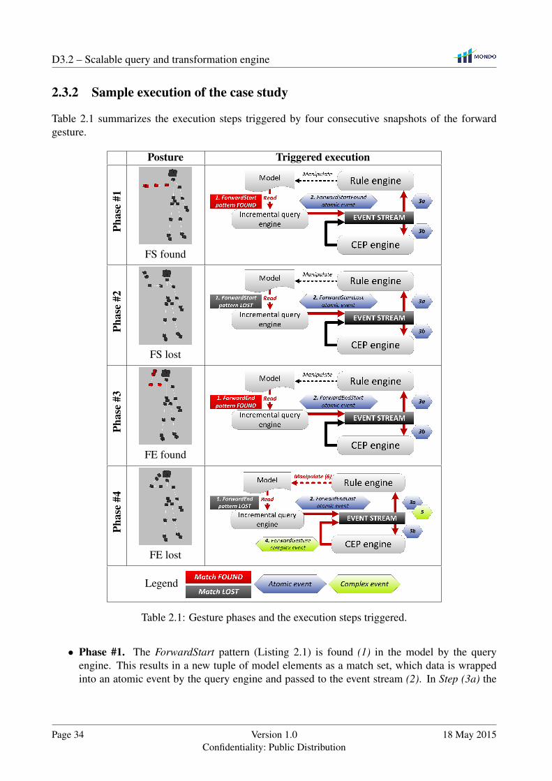
D3.2 – Scalable query and transformation engine
2.3.2 Sample execution of the case study
Table 2.1 summarizes the execution steps triggered by four consecutive snapshots of the forwardgesture.
Posture Triggered execution
Phas
e#1
FS found
Phas
e#2
FS lost
Phas
e#3
FE found
Phas
e#4
FE lost
Legend
Table 2.1: Gesture phases and the execution steps triggered.
• Phase #1. The ForwardStart pattern (Listing 2.1) is found (1) in the model by the queryengine. This results in a new tuple of model elements as a match set, which data is wrappedinto an atomic event by the query engine and passed to the event stream (2). In Step (3a) the
Page 34 Version 1.0Confidentiality: Public Distribution
18 May 2015

D3.2 – Scalable query and transformation engine
Rule engine processes the atomic event and if a transformation rule is activated, the appropriatetransformation gets executed. However, since no transformation rules are associated with eventForwardStart, no transformation rules are activated at this point. In Step (3b) the CEP engineprocesses the atomic event as well and updates the complex event candidates, i.e. the partiallymatched complex events.• Phase #2 and #3. In the next phase, we detect that a match of the ForwardStart pattern is lost.
The same steps are executed as above, only this time an atomic event of type ForwardStartLostis published on the event stream and processed by the Rule engine and the CEP engine. InPhase #3, a ForwardEndFound atomic event is identified and placed on the stream.• Phase #4. The ForwardEnd pattern is lost and a ForwardEndLost atomic event is published
on the event stream consequently. Now there will be additional steps triggered after Step (3b).After having processed the ForwardEndLost atomic event, the CEP engine detects the For-wardGesture complex event, instantiates the appropriate complex event instance consequentlyand publishes it on the event stream Step (4). In Step (5) the Rule engine processes the com-plex event and checks for activated transformation rules. The rule defined in Listing 2.5 willbe activated and the appropriate action will be executed in Step (6).
2.4 Evaluation
To estimate the performance and scalability of our tool, we had to design a semi-synthetic benchmarkbased on the use case of Section 2.1. The reason for this is that Microsoft KINECT can only detect atmost two bodies, and the refresh rate is a fixed 25 frames per second (FPS), which is easily processedby our CEP engine.
Evaluation setup. The core of the simulation is a previously recorded real execution sequence inwhich the right arm is rotated. A full arm cycle consists of 12 positions, i.e. 12 frames. Every cycleyields exactly one Forward gesture (Figure 2.2) composed of the sequence of 4 atomic events; andevery cycle also yields two atomic events considered as noise. This makes 6 atomic events generatedfor each cycle.
Our simulations aim at stress testing our CEP prototype, which is carried out by multiplying thissequence along a different number of bodies in the model. This part of the benchmark scenario isartificial in the sense that KINECT can handle at most two bodies, but the actual positions of thebodies remain realistic.
After starting the simulations, we primarily measure the number of detected complex events persecond. From this rate, we calculate the effective processing rate (i.e. the theoretical upper limit) ofthe CEP engine measured in frames per second (FPS). This value is compared to the original FPSrate of the KINECT sensor. We continue increasing the number of bodies up to the point when theprocessing rate is greater than the recording rate.
Summary of results. Table 2.6 summarizes our results. Rows represent the individual measure-ments with respect to the increasing number of bodies Body count. The next two columns present the
18 May 2015 Version 1.0Confidentiality: Public Distribution
Page 35
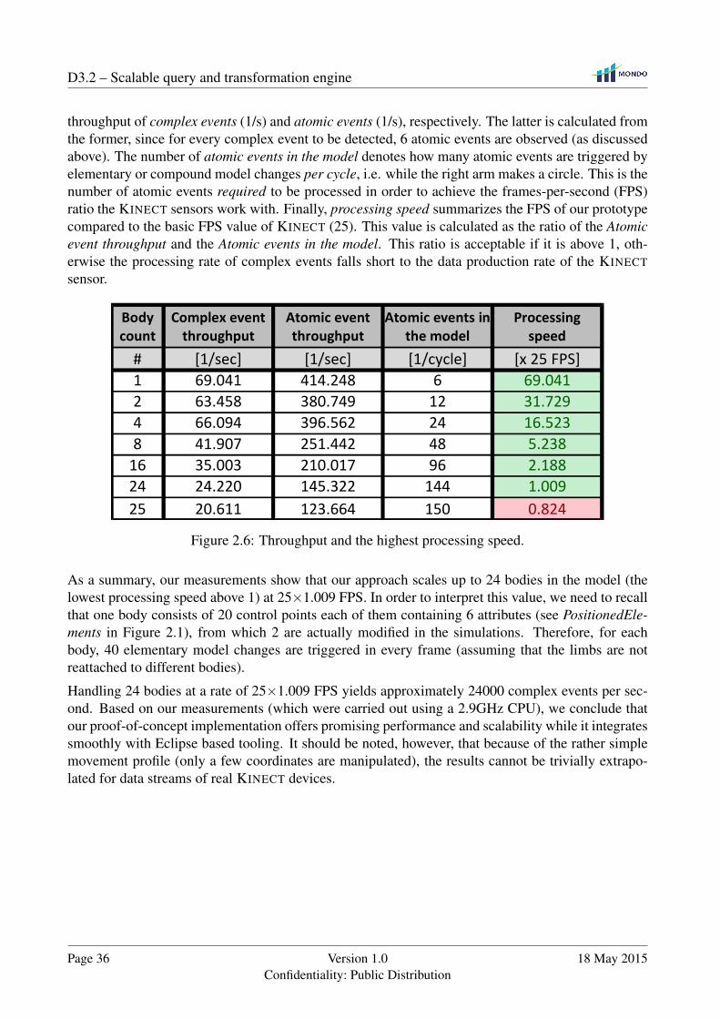
D3.2 – Scalable query and transformation engine
throughput of complex events (1/s) and atomic events (1/s), respectively. The latter is calculated fromthe former, since for every complex event to be detected, 6 atomic events are observed (as discussedabove). The number of atomic events in the model denotes how many atomic events are triggered byelementary or compound model changes per cycle, i.e. while the right arm makes a circle. This is thenumber of atomic events required to be processed in order to achieve the frames-per-second (FPS)ratio the KINECT sensors work with. Finally, processing speed summarizes the FPS of our prototypecompared to the basic FPS value of KINECT (25). This value is calculated as the ratio of the Atomicevent throughput and the Atomic events in the model. This ratio is acceptable if it is above 1, oth-erwise the processing rate of complex events falls short to the data production rate of the KINECT
sensor.
# [1/sec] [1/sec] [1/cycle] [x 25 FPS]
1 69.041 414.248 6 69.041
2 63.458 380.749 12 31.729
4 66.094 396.562 24 16.523
8 41.907 251.442 48 5.238
16 35.003 210.017 96 2.188
24 24.220 145.322 144 1.009
25 20.611 123.664 150 0.824
Body
count
Complex event
throughput
Atomic event
throughput
Atomic events in
the model
Processing
speed
Figure 2.6: Throughput and the highest processing speed.
As a summary, our measurements show that our approach scales up to 24 bodies in the model (thelowest processing speed above 1) at 25×1.009 FPS. In order to interpret this value, we need to recallthat one body consists of 20 control points each of them containing 6 attributes (see PositionedEle-ments in Figure 2.1), from which 2 are actually modified in the simulations. Therefore, for eachbody, 40 elementary model changes are triggered in every frame (assuming that the limbs are notreattached to different bodies).
Handling 24 bodies at a rate of 25×1.009 FPS yields approximately 24000 complex events per sec-ond. Based on our measurements (which were carried out using a 2.9GHz CPU), we conclude thatour proof-of-concept implementation offers promising performance and scalability while it integratessmoothly with Eclipse based tooling. It should be noted, however, that because of the rather simplemovement profile (only a few coordinates are manipulated), the results cannot be trivially extrapo-lated for data streams of real KINECT devices.
Page 36 Version 1.0Confidentiality: Public Distribution
18 May 2015
Conclusions
In Chapter 1 of this deliverable we focused in implementing and evaluating an experimental prototypeof reactive transformation engine that can cover a wide range of application scenarios. The MONDOproject shows that the use of a declarative MTL like ATL, besides benefits (yet to be proved) inexpressiveness and abstraction, allows developers to easily build autonomous data-flow systems thatreact to application events, with advantages in terms of development and computation time.
In Chapter 2 we identified and addressed a novel class of streaming transformations [37] for livemodels where the models themselves are available, but they evolve at a very fast rate (resulting inthousands of changes in every second). Elementary model changes (e.g. EMF notifications) as wellas derived compound changes of match sets of change patterns [6] are encapsulated into a stream ofatomic events. This event stream is consumed by complex event processing techniques to identifycomplex series of events (appearing within a timeframe) and execute streaming transformations upontheir detection. We proposed a language built as an extension of an existing query and transformationlanguage with execution semantics, and presented an integrated model-based complex event process-ing engine VIATRA-CEP to a proof-of-concept prototype. Initial experimental evaluation over acomplex gesture recognition case study demonstrates the practical feasibility of our approach. Amain advantage of our framework is that models are not required to be kept in memory during trans-formation as only the stream of events is processed. Elementary and compound structural changes arefirst encapsulated into atomic changes by incremental model queries. Atomic events contain only thefew relevant contextual model elements required to identify complex events and trigger related trans-formations for complex event processing. As a result, the time and structural dimension of changesis kept separated both from a conceptual and a tooling viewpoint.
We envision several lines for future work:
Classification and characterization of transformation scenarios. We have shown how our re-active prototype can be configured to cover a wide range of transformation scenarios like one-shottransformations for scenarios requiring access to the full target model (e.g., metric calculation,model serialization and persistence) or incremental transformation for performing target-source livesynchronization (e.g., live model editors). As a future work we intend to provide a classification oftransformation problems, characterizing their particularities and analyzing the best transformationapproach to tackle them.
Extended support for ATL. Our prototype does not yet implement a complete reactive paradigmfor ATL: currently we don’t support all the ATL features and we don’t have any support to trans-
37
D3.2 – Scalable query and transformation engine
actional or concurrent updates. Moreover, our reactive engine works in a synchronous way, i.e.,when a source model element change is produced or a target model element is requested, the clientapplication must wait until the transformation engine has finished its computation. Conversely, asyn-chronous computation is likely to be useful when dealing with updates affecting a big subset of thetarget models or when the request for a feature involves heavy computations. We plan to study theseaspects in future work.
Extensions to the paradigm. In the context of model transformations, the reactive paradigm canbe further extended with advanced features like back-propagation and support for target updatesand retainment rules. Furthermore, we plan to provide support to other reactivity features than re-sponsiveness and message passing. Currently we are working in a distributed and fault toleranttransformation engine, that along with our current reactive engine will enable a good resiliency andreliability.
Networks of transformation. We previously mentionned that MDE applications commonly involvenetworks of transformations. In this sense, we started working on a API hiding the complexities ofdirectly configuring such chains. This API will be later on lifted to a more complete and generic DSL.
Performance and memory footprint improvement Keeping the trace and other accessory informa-tion permanently in memory impacts the effiency and the memory footprint of the reactive engine. asfuture work we intend to investigate a mechanism to 1) serialize traces and other accessory informa-tion 2) load/unload in memory just the required portions of this information. We believe that a staticanalysis of the transformation could be very helpful. it could be also used to improve the invalidationprocess and the error handling by helping to better calculate the chain of invalidation/revalidationoperations needed to leave the system in a safe state.
Streaming transformations. We plan several enhancements to the change pattern modeling lan-guage, which currently lacks desirable features, such as branching patterns [3], negative patterns andtemporal algebraic structures [22]. We envisage a general canonical form of event pattern defini-tions, which every event pattern could be translated into and would enable optimization steps priorto the execution. We plan to apply the framework in various domains. Models at runtime (M@RT)[8] aim at representing the prevailing state of the underlying system. Processing streams of changesor change events arising from these models, instead of approaching them with batch or incrementaltransformations seems to be a natural fit.
Page 38 Version 1.0Confidentiality: Public Distribution
18 May 2015

Bibliography
[1] Matthias Baldauf, Schahram Dustdar, and Florian Rosenberg. A Survey on Context-AwareSystems. Int. J. Ad Hoc Ubiquitous Comput., 2(4):263–277, June 2007.
[2] Olivier Beaudoux, Arnaud Blouin, Olivier Barais, and Jean-Marc Jézéquel. Active operationson collections. In MoDELS, volume 6394 of Lecture Notes in Computer Science, pages 91–105.Springer, 2010.
[3] Mordechai Ben-Ari, Zohar Manna, and Amir Pnueli. The Temporal Logic of Branching Time.In Proceedings of the 8th ACM SIGPLAN-SIGACT Symposium on Principles of ProgrammingLanguages, POPL ’81, pages 164–176, New York, NY, USA, 1981. ACM.
[4] G. Bergmann, I. Ráth, and D. Varró. Parallelization of graph transformation based on incre-mental pattern matching. Electronic Communications of EASST, 18, 2009.
[5] Gábor Bergmann, András Ökrös, István Ráth, Dániel Varró, and Gergely Varró. Incrementalpattern matching in the viatra model transformation system. ACM Press, New York, USA,2008.
[6] Gábor Bergmann, István Ráth, Gergely Varró, and Dániel Varró. Change-driven model transfor-mations. change (in) the rule to rule the change. Software and Systems Modeling, 11:431–461,2012 2012.
[7] Gerard Berry and Georges Gonthier. The Esterel Synchronous Programming Language: De-sign, Semantics, Implementation. Science of Computer Programming, 19(2):87–152, 1992.
[8] G. Blair, N. Bencomo, and R.B. France. Models@ run.time. Computer, 42(10):22–27, 2009.
[9] Frédéric Boussinot. Reactive c: An extension of c to program reactive systems. Software:Practice and Experience, 21(4):401–428, 1991.
[10] G.E.P. Box, G.M. Jenkins, and G.C. Reinsel. Time Series Analysis: Forecasting and Control.Wiley Series in Probability and Statistics. Wiley, 2008.
[11] John Boyland. Incremental evaluators for remote attribute grammars. electronic Notes in The-oretical Computer Science, 65(3):9–29, 2002.
[12] Ruth Breu, Berthold Agreiter, Matthias Farwick, Michael Felderer, Michael Hafner, and FrankInnerhofer-Oberperfler. Living Models - Ten Principles for Change-Driven Software Engineer-ing. Int. J. Software and Informatics, 5(1-2):267–290, 2011.
39
D3.2 – Scalable query and transformation engine
[13] Frank Budinsky, Stephen A. Brodsky, and Ed Merks. Eclipse Modeling Framework. PearsonEducation, 2003.
[14] J. Cabot and E. Teniente. Incremental evaluation of OCL constraints. Lecture Notes in Com-puter Science, 4001:81, 2006.
[15] Jan Carlson. An Intuitive and Resource-Efficient Event Detection Algebra. http://citeseerx.ist.psu.edu/viewdoc/summary?doi=10.1.1.3.9957, 2004. Ac-cessed: 2014-07-01.
[16] Manuel Clavel, Marina Egea, and Miguel Angel García de Dios. Building an efficient compo-nent for OCL evaluation. Electronic Communications of EASST, 15, 2008.
[17] Benoît Combemale, Xavier Thirioux, and Benoit Baudry. Formally Defining and IteratingInfinite Models. In Robert B. France, Jürgen Kazmeier, Ruth Breu, and Colin Atkinson, editors,Model Driven Engineering Languages and Systems - 15th International Conference, MODELS2012, Innsbruck, Austria, September 30-October 5, 2012. Proceedings, volume 7590 of LNCS,pages 119–133. Springer, 2012.
[18] István Dávid. Complex Event Processing In Model Transformation Systems. Master’s thesis,Department of Measurement and Information Systems, Budapest University of Technology andEconomics, 2013.
[19] István Dávid and István Ráth. Realtime gesture recognition with Jnect and Esper. Tech demoat EclipseCon Europe 2012, http://incquery.net/incquery/demos/jnect. Ac-cessed: 2014-07-01.
[20] Eclipse Foundation. Xtext 2.6.0 Documentation. http://www.eclipse.org/Xtext/documentation/2.6.0/Xtext%20Documentation.pdf. Accessed: 2014-07-01.
[21] EsperTech Inc. Esper Official Website. http://esper.codehaus.org. Accessed: 2014-07-01.
[22] Dov M Gabbay. Temporal Logic: Mathematical Foundations and Computational Aspects.Clarendon Press, Oxford, 1994.
[23] Holger Giese and Robert Wagner. From model transformation to incremental bidirectionalmodel synchronization. Software & Systems Modeling, 8(1):21–43, 2008.
[24] D. Harel and A. Pnueli. On the development of reactive systems, pages 477–498. Springer-Verlag Inc., New York, USA, 1985.
[25] D. Hearnden, M. Lawley, and K. Raymond. Incremental model transformation for the evolutionof model-driven systems. Lecture Notes in Computer Science, 4199:321, 2006.
[26] Jonas Helming, Eugen Neufeld, and Maximilian Koegel. jnect – An Eclipse Plug-In pro-viding a Java Adapter for the Microsoft Kinect SDK. http://code.google.com/a/eclipselabs.org/p/jnect/. Accessed: 2014-07-01.
Page 40 Version 1.0Confidentiality: Public Distribution
18 May 2015
D3.2 – Scalable query and transformation engine
[27] Peter Henderson and James H. Morris, Jr. A lazy evaluator. In Proc. of the 3rd ACM SIGACT-SIGPLAN symposium on Principles on programming languages, POPL ’76, pages 95–103.ACM, 1976.
[28] Paul Hudak, John Hughes, Simon L. Peyton Jones, and Philip Wadler. A history of Haskell:being lazy with class. In HOPL, pages 1–55. ACM, 2007.
[29] Frédéric Jouault and Ivan Kurtev. Transforming Models with ATL. In MoDELS Satellite Events,pages 128–138, 2005.
[30] Frédéric Jouault and Massimo Tisi. Towards incremental execution of atl transformations. InLaurence Tratt and Martin Gogolla, editors, ICMT, volume 6142 of Lecture Notes in ComputerScience, pages 123–137. Springer, 2010.
[31] David C. Luckham. The Power of Events: An Introduction to Complex Event Processing inDistributed Enterprise Systems. Addison-Wesley Longman Publishing Co., Inc., Boston, MA,USA, 2001.
[32] Microsoft Corp. Microsoft Kinect official website. http://www.microsoft.com/en-us/kinectforwindows/. Accessed: 2014-07-01.
[33] OMG. 2.0 OCL specification. Adopted Specification (ptc/03-10-14), 2003.
[34] OMG. MOF QVT Final Adopted Specification. Object Management Group, 2005.
[35] Maarten Pennings, S. Doaitse Swierstra, and Harald Vogt. Using cached functions and construc-tors for incremental attribute evaluation. In Maurice Bruynooghe and Martin Wirsing, editors,PLILP, volume 631 of Lecture Notes in Computer Science, pages 130–144. Springer, 1992.
[36] I. Ráth, G. Bergmann, A. Okrös, and D. Varró. Live model transformations driven by incremen-tal pattern matching. Theory and Practice of Model Transformations, 5063:107–121, 2008.
[37] Jesús Sánchez Cuadrado and Juan Lara. Streaming model transformations: Scenarios, chal-lenges and initial solutions. In Keith Duddy and Gerti Kappel, editors, Theory and Practiceof Model Transformations, volume 7909 of Lecture Notes in Computer Science, pages 1–16.Springer Berlin Heidelberg, 2013.
[38] Steffen Schott and Markus L. Noga. Lazy XSL transformations. In ACM Symposium on Docu-ment Engineering, pages 9–18. ACM, 2003.
[39] Hui Song, Gang Huang, Franck Chauvel, Wei Zhang, Yanchun Sun, Weizhong Shao, and HongMei. Instant and Incremental QVT Transformation for Runtime Models. In Proceedings of the14th International Conference on Model Driven Engineering Languages and Systems, MOD-ELS’11, pages 273–288, Berlin, Heidelberg, 2011. Springer-Verlag.
[40] Gabriele Taentzer, Karsten Ehrig, Esther Guerra, J. de Lara, L. Lengyel, Tihamer Levendovszky,Ulrike Prange, D. Varró, and S. Varró-Gyapay. Model transformation by graph transformation:A comparative study. In Proc. of Workshop Model Transformation in Practice, 2005.
18 May 2015 Version 1.0Confidentiality: Public Distribution
Page 41
D3.2 – Scalable query and transformation engine
[41] Massimo Tisi, Salvador Martínez, Frédéric Jouault, and Jordi Cabot. Lazy execution of model-to-model transformations. In MoDELS, Lecture Notes in Computer Science, pages 32–46.Springer, 2011.
[42] Zoltán Ujhelyi, Gábor Bergmann, Ábel Hegedüs, Ákos Horváth, Benedek Izsó, Zoltán Szat-mári, and Dániel Varró. An Integrated Development Environment for Live Model Queries.Science of Computer Programming, 2013.
[43] Eelco Visser. Program transformation with Stratego/XT: Rules, strategies, tools, and systemsin Stratego/XT 0.9. In Domain-Specific Program Generation, volume 3016 of Lecture Notes inComputer Science, pages 216–238. Springer, 2003.
[44] Thomas Vogel, Stefan Neumann, Stephan Hildebrandt, Holger Giese, and Basil Becker. Incre-mental Model Synchronization for Efficient Run-Time Monitoring. In Sudipto Ghosh, editor,Models in Software Engineering, Workshops and Symposia at MODELS 2009, Denver, CO,USA, October 4-9, 2009, Reports and Revised Selected Papers, volume 6002 of LNCS, pages124–139, 2009.
[45] Harald Vogt, Doaitse Swierstra, and Matthijs Kuiper. Efficient incremental evaluation of higherorder attribute grammars. In Programming Language Implementation and Logic Programming,pages 231–242. Springer, 1991.
[46] Zhanyong Wan and Paul Hudak. Functional reactive programming from first principles. SIG-PLAN Not., 35:242–252, May 2000.
[47] Jonne Van Wijngaarden and Eelco Visser. Program transformation mechanics: A classificationof mechanisms for program transformation with a survey of existing transformation systems.Technical report, UU-CS, 2003.
[48] Yingfei Xiong, Dongxi Liu, Zhenjiang Hu, Haiyan Zhao, Masato Takeichi, and Hong Mei.Towards automatic model synchronization from model transformations. Proc. of the twenty-second IEEE/ACM international conference on Automated software engineering ASE07, page164, 2007.
[49] Koen Yskout, Riccardo Scandariato, and Wouter Joosen. Change patterns: Co-evolving re-quirements and architecture. Software and Systems Modeling, 2012.
Page 42 Version 1.0Confidentiality: Public Distribution
18 May 2015


![ZXY]djl` cbkpyqv^riu - Wing On Travel · 26](https://static.fdocuments.us/doc/165x107/5e63bf0a9168961cd91b0bae/zxydjl-cbkpyqvriu-wing-on-travel-26.jpg)