ARMINES, BME, UNINOVA, YORK - Ningapi.ning.com/files/zxy*xRp5iQ42n1g40skoWswxaHXgPzmwV9JPNq5... ·...
45
Project Number 611125 D3.3 – Cloud-enabled query and transformation engine Version 1.0 23 December 2015 Final Public Distribution ARMINES, BME, UNINOVA, YORK Project Partners: ARMINES, Autonomous University of Madrid, BME, IKERLAN, Soft-Maint, SOFTEAM, The Open Group, UNINOVA, University of York Every effort has been made to ensure that all statements and information contained herein are accurate, however the Project Partners accept no liability for any error or omission in the same. © 2015 Copyright in this document remains vested in the MONDO Project Partners.
Transcript of ARMINES, BME, UNINOVA, YORK - Ningapi.ning.com/files/zxy*xRp5iQ42n1g40skoWswxaHXgPzmwV9JPNq5... ·...
Project Number 611125
D3.3 – Cloud-enabled query and transformation engine
Version 1.023 December 2015
Final
Public Distribution
ARMINES, BME, UNINOVA, YORK
Project Partners: ARMINES, Autonomous University of Madrid, BME, IKERLAN, Soft-Maint,SOFTEAM, The Open Group, UNINOVA, University of York
Every effort has been made to ensure that all statements and information contained herein are accurate, howeverthe Project Partners accept no liability for any error or omission in the same.
© 2015 Copyright in this document remains vested in the MONDO Project Partners.

D3.3 – Cloud-enabled query and transformation engine
Project Partner Contact Information
ARMINES Autonomous University of MadridMassimo Tisi Juan de LaraRue Alfred Kastler 4 Calle Einstein 344070 Nantes Cedex, France 28049 Madrid, SpainTel: +33 2 51 85 82 09 Tel: +34 91 497 22 77E-mail: [email protected] E-mail: [email protected]
BME IKERLANDaniel Varro Salvador TrujilloMagyar Tudosok korutja 2 Paseo J.M. Arizmendiarrieta 21117 Budapest, Hungary 20500 Mondragon, SpainTel: +36 146 33598 Tel: +34 943 712 400E-mail: [email protected] E-mail: [email protected]
Soft-Maint SOFTEAMVincent Hanniet Alessandra BagnatoRue du Chateau de L’Eraudiere 4 Avenue Victor Hugo 2144300 Nantes, France 75016 Paris, FranceTel: +33 149 931 345 Tel: +33 1 30 12 16 60E-mail: [email protected] E-mail: [email protected]
The Open Group UNINOVAScott Hansen Pedro MalóAvenue du Parc de Woluwe 56 Campus da FCT/UNL, Monte de Caparica1160 Brussels, Belgium 2829-516 Caparica, PortugalTel: +32 2 675 1136 Tel: +351 212 947883E-mail: [email protected] E-mail: [email protected]
University of YorkDimitris KolovosDeramore LaneYork YO10 5GH, United KingdomTel: +44 1904 32516E-mail: [email protected]
Page ii Version 1.0Confidentiality: Public Distribution
23 December 2015
Contents
1 Introduction 2
2 Distributed ATL 3
2.1 Running Example: Model Transformation for Data-Flow Analysis . . . . . . . . . . 4
2.2 ATL on MapReduce . . . . . . . . . . . . . . . . . . . . . . . . . . . . . . . . . . . 7
2.2.1 ATL and MapReduce Alignment . . . . . . . . . . . . . . . . . . . . . . . . 8
2.3 Tool Support . . . . . . . . . . . . . . . . . . . . . . . . . . . . . . . . . . . . . . 13
2.3.1 Distributed Transformation Engine . . . . . . . . . . . . . . . . . . . . . . . 13
2.3.2 Data Distribution . . . . . . . . . . . . . . . . . . . . . . . . . . . . . . . . 13
2.3.3 Tool Limitations . . . . . . . . . . . . . . . . . . . . . . . . . . . . . . . . 14
2.4 Experimental Evaluation . . . . . . . . . . . . . . . . . . . . . . . . . . . . . . . . 14
2.4.1 Experiment I: Speed-Up Curve . . . . . . . . . . . . . . . . . . . . . . . . . 16
2.4.2 Experiment II: Size/Speed-Up Correlation . . . . . . . . . . . . . . . . . . . 16
3 INCQUERY-D 18
3.1 Running Example: a DSL for Railways System Design . . . . . . . . . . . . . . . . 19
3.1.1 Queries . . . . . . . . . . . . . . . . . . . . . . . . . . . . . . . . . . . . . 19
3.1.2 Transformations . . . . . . . . . . . . . . . . . . . . . . . . . . . . . . . . 20
3.2 A Distributed Incremental Model Query Framework . . . . . . . . . . . . . . . . . . 21
3.2.1 Architecture . . . . . . . . . . . . . . . . . . . . . . . . . . . . . . . . . . . 21
3.2.2 The Rete Algorithm in a Distributed Environment . . . . . . . . . . . . . . . 23
3.3 Evaluation . . . . . . . . . . . . . . . . . . . . . . . . . . . . . . . . . . . . . . . . 26
3.3.1 Benchmark Scenario . . . . . . . . . . . . . . . . . . . . . . . . . . . . . . 26
3.3.2 Benchmark Architecture . . . . . . . . . . . . . . . . . . . . . . . . . . . . 27
3.3.3 Results . . . . . . . . . . . . . . . . . . . . . . . . . . . . . . . . . . . . . 28
iii

D3.3 – Cloud-enabled query and transformation engine
4 Related Work 314.1 Distributed Batch Computation . . . . . . . . . . . . . . . . . . . . . . . . . . . . . 31
4.2 Distributed Incremental Query Evaluation . . . . . . . . . . . . . . . . . . . . . . . 32
5 Summary and Future Work 345.1 Contributions . . . . . . . . . . . . . . . . . . . . . . . . . . . . . . . . . . . . . . 34
5.2 Future Work . . . . . . . . . . . . . . . . . . . . . . . . . . . . . . . . . . . . . . . 34
Page iv Version 1.0Confidentiality: Public Distribution
23 December 2015

D3.3 – Cloud-enabled query and transformation engine
Document Control
Version Status Date0.2 First draft 2 Novembre 20150.6 Full draft 15 Novembre 20151.0 Final version 23 Decembre 2015
23 December 2015 Version 1.0Confidentiality: Public Distribution
Page v
D3.3 – Cloud-enabled query and transformation engine
Executive Summary
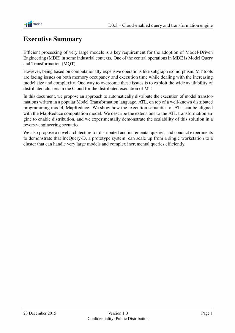
Efficient processing of very large models is a key requirement for the adoption of Model-DrivenEngineering (MDE) in some industrial contexts. One of the central operations in MDE is Model Queryand Transformation (MQT).
However, being based on computationally expensive operations like subgraph isomorphism, MT toolsare facing issues on both memory occupancy and execution time while dealing with the increasingmodel size and complexity. One way to overcome these issues is to exploit the wide availability ofdistributed clusters in the Cloud for the distributed execution of MT.
In this document, we propose an approach to automatically distribute the execution of model transfor-mations written in a popular Model Transformation language, ATL, on top of a well-known distributedprogramming model, MapReduce. We show how the execution semantics of ATL can be alignedwith the MapReduce computation model. We describe the extensions to the ATL transformation en-gine to enable distribution, and we experimentally demonstrate the scalability of this solution in areverse-engineering scenario.
We also propose a novel architecture for distributed and incremental queries, and conduct experimentsto demonstrate that IncQuery-D, a prototype system, can scale up from a single workstation to acluster that can handle very large models and complex incremental queries efficiently.
23 December 2015 Version 1.0Confidentiality: Public Distribution
Page 1

Chapter 1
Introduction
Model-Driven Engineering (MDE) is gaining ground in industrial environments, thanks to its promiseof lowering software development and maintenance effort [32]. It has been adopted with successin producing software for several domains like civil engineering [62], car manufacturing [35] andmodernization of legacy software systems [9]. Core concepts of MDE are the centrality of (software,data and system) models in all phases of software engineering and the automation of model processingduring the software life-cycle. Model Transformation (MT) languages have been designed to helpusers specifying and executing these model-graph manipulations. They are often used in implementingtooling for software languages, especially domain-specific [66], e.g. in reverse engineering [9]. TheAtlanMod Transformation Language (ATL) [30] is one of the most popular examples among them,and a plethora of transformations exist addressing different model types and intentions1.
Similarly to other software engineering approaches, MDE has been recently facing the growing com-plexity of data and systems [34], that comes in MDE in the form of Very Large Models (VLMs) [13].For example, the Building Information Modeling language (BIM) [62] contains a rich set of concepts(more than eight hundred) for modeling different aspects of physical facilities and infrastructures. Abuilding model in BIM is typically made of several gigabytes of densely interconnected graph nodes.Existing MDE tools, including MT engines, are based on graph matching and traversing techniquesthat are facing serious scalability issues in terms of memory occupancy and execution time. Thisstands especially when MT execution is limited by the resources of a single machine. In the case studythat we selected for our experimentation, we show how typical MT tasks in the reverse-engineering oflarge Java code bases take several hours to compute in local.
This work Chapter 2 presents a distributed version of ATL and Chapter 3 INCQUERY-D, a distributedincremental query engine.
1The Eclipse Foundation, ATL transformation zoo, http://www.eclipse.org/atl/atlTransformations/, visited on June 2015
2
Chapter 2
Distributed ATL
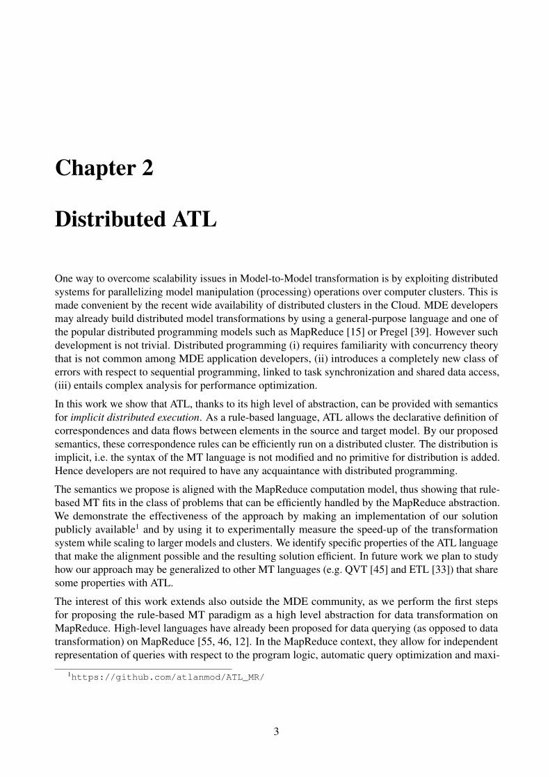
One way to overcome scalability issues in Model-to-Model transformation is by exploiting distributedsystems for parallelizing model manipulation (processing) operations over computer clusters. This ismade convenient by the recent wide availability of distributed clusters in the Cloud. MDE developersmay already build distributed model transformations by using a general-purpose language and one ofthe popular distributed programming models such as MapReduce [15] or Pregel [39]. However suchdevelopment is not trivial. Distributed programming (i) requires familiarity with concurrency theorythat is not common among MDE application developers, (ii) introduces a completely new class oferrors with respect to sequential programming, linked to task synchronization and shared data access,(iii) entails complex analysis for performance optimization.
In this work we show that ATL, thanks to its high level of abstraction, can be provided with semanticsfor implicit distributed execution. As a rule-based language, ATL allows the declarative definition ofcorrespondences and data flows between elements in the source and target model. By our proposedsemantics, these correspondence rules can be efficiently run on a distributed cluster. The distribution isimplicit, i.e. the syntax of the MT language is not modified and no primitive for distribution is added.Hence developers are not required to have any acquaintance with distributed programming.
The semantics we propose is aligned with the MapReduce computation model, thus showing that rule-based MT fits in the class of problems that can be efficiently handled by the MapReduce abstraction.We demonstrate the effectiveness of the approach by making an implementation of our solutionpublicly available1 and by using it to experimentally measure the speed-up of the transformationsystem while scaling to larger models and clusters. We identify specific properties of the ATL languagethat make the alignment possible and the resulting solution efficient. In future work we plan to studyhow our approach may be generalized to other MT languages (e.g. QVT [45] and ETL [33]) that sharesome properties with ATL.
The interest of this work extends also outside the MDE community, as we perform the first stepsfor proposing the rule-based MT paradigm as a high level abstraction for data transformation onMapReduce. High-level languages have already been proposed for data querying (as opposed to datatransformation) on MapReduce [55, 46, 12]. In the MapReduce context, they allow for independentrepresentation of queries with respect to the program logic, automatic query optimization and maxi-
1https://github.com/atlanmod/ATL_MR/
3

D3.3 – Cloud-enabled query and transformation engine
FlowInstrtxt : String
Varname : String
Method ParamSimpleStmt
cfNext * use*def*
(a) ControlFlow metamodel excerpt
FlowInstrtxt : String
MethodSimpleStmt
dfNext *
(b) DataFlow metamodel excerpt
Figure 2.1: Simplified ControlFlow and DataFlow metamodels
mization of query reuse [37]. We want to extend this approach, aiming at obtaining similar benefits indata transformation scenarios.
2.1 Running Example: Model Transformation for Data-FlowAnalysis
While our distribution approach is applicable to model transformations in any domain, to exemplifythe discussion we refer throughout this document to a case study related to the analysis of data-flowsin Java programs. The case study is well-known in the MDE community, being proposed by theTransformation Tool Contest (TTC) 2013 [26] as a benchmark for MT engines. We focus on onephase of the scenario, the transformation of the control-flow diagram of a Java program into a data-flow diagram. Such task would be typically found in real-world model-driven applications on programanalysis and reverse engineering of legacy code [9].
Excerpts of the source and target metamodels of this step are shown in 2.1. In a control-flow diagram(Figure 2.1a), a FlowInstruction (FlowInstr) has a field txt containing the textual code of the instruction,a set of variables it defines or writes (def ), and a set of variables it reads (use). A FlowInstructionpoints to the potential set of instructions that may be executed after it (cfNext). Method signatures andSimpleStatements (SimpleStmt) are kinds of FlowInstruction. A Parameter is a kind of Variable thatis defined in method signatures.
The data-flow diagram (Figure 2.1b) has analogous concepts of FlowInstruction, Method and Sim-pleStatements but a different topology based on the data-flow links among instructions (dfNext). Forevery flow instruction n, a dfNext link has to be created from all nearest control-flow predecessors mthat define a variable which is used by n. Formally [26]:
m→dfNext n⇐⇒ def(m) ∩ use(n) 6= ∅ ∧ ∃ Path m =
n0 →cfNext . . .→cfNext nk = n :
(def(m) ∩ use(n))\( ⋃0<i<k
def(ni))6= ∅
(2.1)
Page 4 Version 1.0Confidentiality: Public Distribution
23 December 2015

D3.3 – Cloud-enabled query and transformation engine
Figure 2.2: ControlFlow2DataFlow transformation example
Figure 2.2 shows an example of models for each metamodel, derived from a small program calculatinga number factorial. As it can be seen in the figure, the transformation changes the topology of themodel graph, the number of nodes and their content, and therefore can be regarded as a representativeexample of general transformations. In this chapter we refer to an ATL implementation of thetransformation named ControlFlow2DataFlow and available at the article website1.
Model transformations in ATL are unidirectional. They are applied to read-only source models andproduce write-only target models. ATL developers are encouraged to use declarative rules to visualizeand implement transformations. Declarative rules abstract the relationship between source and targetelements while hiding the semantics dealing with rule triggering, ordering, traceability managementand so on.
1 module ControlFlow2DataFlow ;2 c r e a t e OUT : DataFlow from IN : ControlFlow ;3 r u l e Method {4 from5 s : ControlFlow !Method6 to7 t : DataFlow !Method (8 txt <− s .txt ,9 dfNext <− s .computeNextDataFlows ( )10 )11 }1213 r u l e SimpleStmt {14 from15 s : ControlFlow !SimpleStmt (not (s . def−>16 isEmpty ( ) and s .use−>isEmpty ( ) ) )17 to18 t : DataFlow !SimpleStmt (19 txt <− s .txt ,20 dfNext <− s .computeNextDataFlows ( )21 )22 }
Listing 2.1: ControlFlow2DataFlow - ATL transformation rules (excerpt)
23 December 2015 Version 1.0Confidentiality: Public Distribution
Page 5
D3.3 – Cloud-enabled query and transformation engine
However, rules can be augmented with imperative sections to simplify the expression of complexalgorithms. Hereafter, we focus on declarative-only ATL.
Languages like ATL are structured in a set of transformation rules encapsulated in a transformation unit.These transformation units are called modules (Listing 2.1, line 1). The query language used in ATLis the OMG’s Object Constraint Language (OCL) [44]. A significant subset of OCL data types andoperations is supported in ATL. Listing 2.1 shows a subset of the rules in the ControlFlow2DataFlowtransformation and Listing 2.2 an excerpt of its OCL queries (helpers).
ATL matched rules are composed of a source pattern and a target pattern. Both of source and targetpatterns might contain one or many pattern elements. Input patterns are fired automatically when aninstance of the source pattern (a match) is identified, and produce an instance of the correspondingtarget pattern in the output model. Implicitly, transient tracing information is built to associate inputelements to their correspondences in the target model.
Source patterns are defined as OCL guards over a set of typed elements, i.e. only combinations ofinput elements satisfying that guard are matched. In ATL, a source pattern lays within the body of theclause ’from’ (Listing 2.1, line 14). For instance, in the rule SimpleStmt, the source pattern (Listing 2.1,line 15) matches an element of type SimpleStmt that defines or uses at least a variable. Output patterns,delimited by the clause ’to’ (Listing 2.1, line 17) describe how to compute the model elements toproduce when the rule is fired, starting from the values of the matched elements. E.g., the SimpleStmtrule produces a single element of type SimpleStmt. A set of OCL bindings specify how to populateeach of the features (attributes and references) of the produced elements. The binding at line 19copies the textual representation of the instruction, and the one at line 20 fills the dfNext link withvalues computed by the computeNextDataFlows OCL helper. The rule for transforming methods isanalogous (Listing 2.1, lines 3-11).
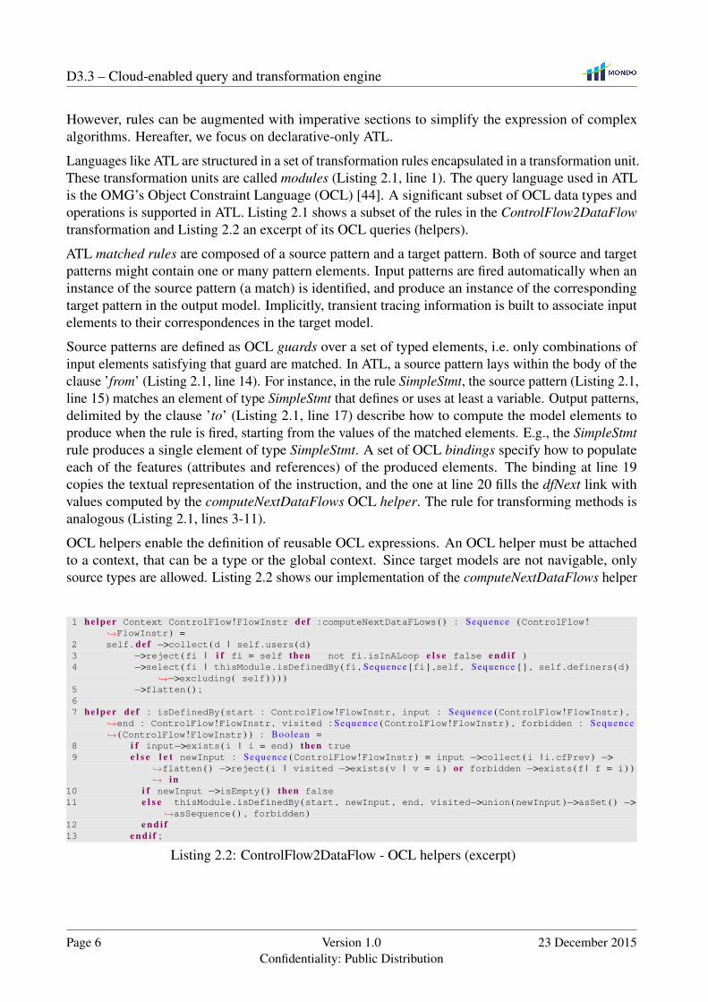
OCL helpers enable the definition of reusable OCL expressions. An OCL helper must be attachedto a context, that can be a type or the global context. Since target models are not navigable, onlysource types are allowed. Listing 2.2 shows our implementation of the computeNextDataFlows helper
1 he lp er Context ControlFlow !FlowInstr def :computeNextDataFLows ( ) : Sequence (ControlFlow !↪→FlowInstr ) =
2 self . def −>collect (d | self .users (d )3 −>reject (fi | i f fi = self then not fi .isInALoop e l s e false e n d i f )4 −>select (fi | thisModule .isDefinedBy (fi , Sequence {fi} ,self , Sequence {} , self .definers (d )
↪→−>excluding ( self ) ) ) )5 −>flatten ( ) ;67 he lp er def : isDefinedBy (start : ControlFlow !FlowInstr , input : Sequence (ControlFlow !FlowInstr ) ,
↪→end : ControlFlow !FlowInstr , visited : Sequence (ControlFlow !FlowInstr ) , forbidden : Sequence↪→ (ControlFlow !FlowInstr ) ) : Boolean =
8 i f input−>exists (i | i = end ) then true9 e l s e l e t newInput : Sequence (ControlFlow !FlowInstr ) = input −>collect (i | i .cfPrev ) −>
↪→flatten ( ) −>reject (i | visited −>exists (v | v = i ) or forbidden −>exists (f | f = i ) )↪→ in
10 i f newInput −>isEmpty ( ) then false11 e l s e thisModule .isDefinedBy (start , newInput , end , visited−>union (newInput )−>asSet ( ) −>
↪→asSequence ( ) , forbidden )12 e n d i f13 e n d i f ;
Listing 2.2: ControlFlow2DataFlow - OCL helpers (excerpt)
Page 6 Version 1.0Confidentiality: Public Distribution
23 December 2015
D3.3 – Cloud-enabled query and transformation engine
derived by the direct translation in OCL of the data-flow definition we gave in Equation 2.1. It has ascontext FlowInstr and returns a sequence of same type (Listing 2.2, line 1).
ATL matched rules are executed in two phases, a match phase and an apply phase. In the firstphase, the rules are applied over source models’ elements satisfying their guards. Each single match,corresponds to the creation of an explicit traceability link. This link connects three items: the rule thattriggered the application, the match, and the newly created output elements (according to the targetpattern). At this stage, only output pattern elements types are considered, bindings evaluation is left tothe next phase.
The apply phase deals with the initialization of output elements’ features. Every feature is associatedto a binding in an output pattern element of a given rule application. Indeed, a rule applicationcorresponds to a trace link. Features initialization is performed in two steps, first the correspondingbinding expression is computed. Resulting in a collection of elements, it is then passed to a resolutionalgorithm (called resolve algorithm) for final update into the output model. The resolve algorithmbehaves differently according to the type of each element. If the type is primitive (in case of attributes)or target, then it is directly assigned to the feature. Otherwise, if it is a source element type, it is firstresolved to its respective target element – using the tracing information – before being assigned tothe feature. Thanks to this algorithm we are able to initialize the target features without needing tonavigate the target models.
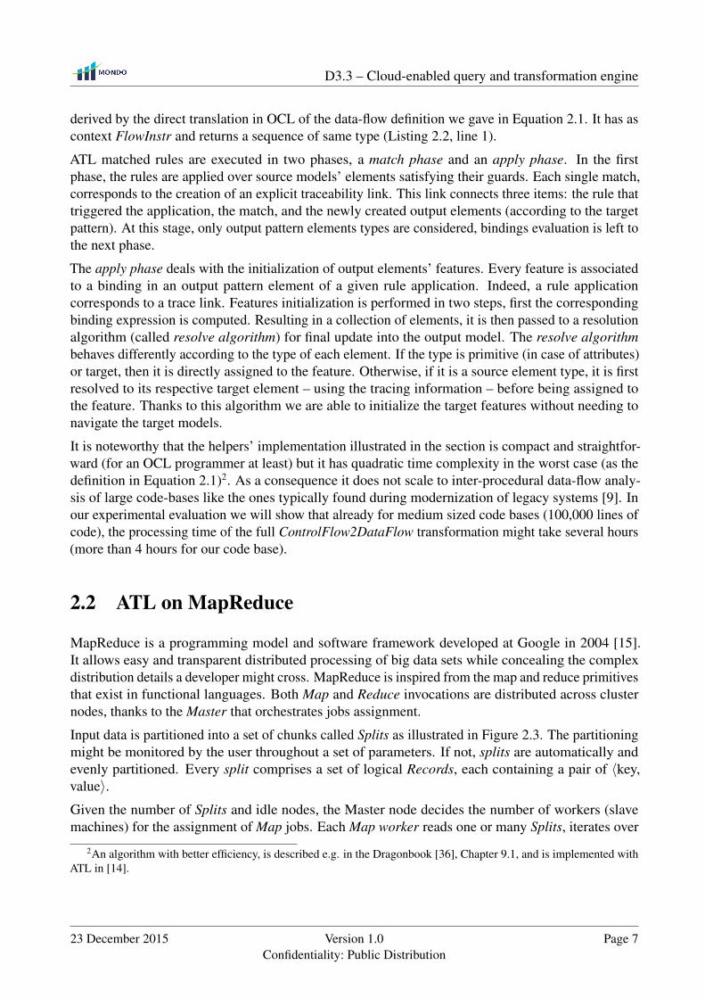
It is noteworthy that the helpers’ implementation illustrated in the section is compact and straightfor-ward (for an OCL programmer at least) but it has quadratic time complexity in the worst case (as thedefinition in Equation 2.1)2. As a consequence it does not scale to inter-procedural data-flow analy-sis of large code-bases like the ones typically found during modernization of legacy systems [9]. Inour experimental evaluation we will show that already for medium sized code bases (100,000 lines ofcode), the processing time of the full ControlFlow2DataFlow transformation might take several hours(more than 4 hours for our code base).
2.2 ATL on MapReduce
MapReduce is a programming model and software framework developed at Google in 2004 [15].It allows easy and transparent distributed processing of big data sets while concealing the complexdistribution details a developer might cross. MapReduce is inspired from the map and reduce primitivesthat exist in functional languages. Both Map and Reduce invocations are distributed across clusternodes, thanks to the Master that orchestrates jobs assignment.
Input data is partitioned into a set of chunks called Splits as illustrated in Figure 2.3. The partitioningmight be monitored by the user throughout a set of parameters. If not, splits are automatically andevenly partitioned. Every split comprises a set of logical Records, each containing a pair of 〈key,value〉.Given the number of Splits and idle nodes, the Master node decides the number of workers (slavemachines) for the assignment of Map jobs. Each Map worker reads one or many Splits, iterates over
2An algorithm with better efficiency, is described e.g. in the Dragonbook [36], Chapter 9.1, and is implemented withATL in [14].
23 December 2015 Version 1.0Confidentiality: Public Distribution
Page 7

D3.3 – Cloud-enabled query and transformation engine
Remote read
<+, 1>
<+ , 1>
<*, 1>
< , 1>
<+, 1><*, 1>
< , 1>
<*, 1>
<+, 1>
Log0
Log1
Log2
Log3
Log4
Log5
Log6
Log7
Log8
SP
LIT1
SP
LIT2
SP
LIT3
Write result
<*, 1><*, 1><*, 1>< , 1>< , 1>
<+, 1><+, 1><+, 1><+, 1>
Map Reduce
Worker
Read splitLocalwrite <*, 3>
< , 2>
<+, 4>
Record
Figure 2.3: MapReduce programming model overview
the Records, processes the 〈key, value〉 pairs and stores locally the intermediate 〈key, value〉 pairs. Inthe meanwhile, the Master receives periodically the location of these pairs. When Map workers finish,the Master forwards these locations to the Reduce workers that sort them so that all occurrences of thesame key are grouped together. The mapper then passes the key and list of values to the user-definedreduce function. Following the reduce tasks achievement, an output result is generated per reduce task.Output results do not need to be always combined, especially if they will subsequently be processedby other distributed applications.
Let’s take a closer look to the MapReduce programming model by means of a simple example, depictedin 2.3. Assume we have set of log entries coming from a git repository. Each entry contains informationabout actions performed over a particular file (creation→ + , deletion→ X , or modification→ ∗ ).We want to know how many times each action was performed, using MapReduce. The master evenlysplits the entries among workers. For every record (log entry), the map worker extracts the action typeand creates a 〈key,value〉 pair with a key the action itself and value ’1’. In the reduce phase, pairswith the same key are grouped together. In our example, the modification and deletion go to the firstreducer, while the creation goes to the second one. For each group, the reducer combines the pairs,and creates a 〈key,value〉 pair, but this time with value the sum of the values with same key. This valuerefers to how many times the action occurred in the logs.
Much of the interest of MapReduce is due to its fault-tolerant processing. The Master keeps track ofthe evolution of every worker execution. If after a certain amount of time a worker does not react, it isconsidered as idle and the job is re-assigned to another worker.
2.2.1 ATL and MapReduce Alignment
Transformations in ATL could be regarded as the union of elementary transformation tasks, whereeach takes charge of transforming a pattern of model elements. The approach we are proposing followsa data-distribution scheme, where each one of the nodes that are computing in parallel takes charge oftransforming a part of the input model. This is made possible, thanks to the semantics alignment forATL distributed execution with MapReduce described in this section.
However, implicit data distribution is not trivial for transformation languages where rules appliedto different parts of the model can interact in complex ways with each other. As result of ATL’s
Page 8 Version 1.0Confidentiality: Public Distribution
23 December 2015

D3.3 – Cloud-enabled query and transformation engine
int fact(int a)
int r = 1;
while (a>0)
r *= a--;
return r;
a
r
int fact(int a)
int r = 1;
while (a>0)
r *= a--;
return r;
int fact(int a)
int r = 1;
while (a>0)
r *= a--;
return r;
Map 1 output
Map 2 output
Reduce outputInput ModelLocal match\apply Global resolve
Figure 2.4: ControlFlow2DataFlow example on MapReduce
execution semantics, especially four specific properties of the language (below), we argue that inter-rule communication is made discernible. More precisely, interaction among ATL transformation rulesis reduced to bindings resolution, where a target element’s feature needs to reference to other targetelements created by other rules:
1. Locality. Each ATL rule is the only one responsible of the computation of the elements it creates,i.e., the rule that creates the element is also responsible of initializing its features. In case of bi-directional references, responsibility is shared among the rules that create the source and thetarget ends of the reference.
2. Single assignment on target properties. The assignment of a single-valued property in a targetmodel element happens only once in the transformation execution. Multi-valued properties canbe updated only for adding values, but never deleting them.
3. Non-recursive rule application. Model elements that are produced by ATL rules are notsubject to further matches. As a consequence, new model elements can not be created asintermediate data to support the computation. This differentiates ATL from typically recursivegraph-transformation languages. This should not be confused with recursion in OCL helpers,that are responsible for intermediate computations over the source models, not target ones.
4. Forbidden target navigation. Rules are not allowed to navigate the part of the target model thathas already been produced, to avoid assumptions on the rule execution order. Thanks to theresolve algorithm along with the trace links that it is made possible.
These properties strongly reduce the possible kinds of interaction among ATL rules, and allow us todecouple rule applications and execute them in independent execution units, as explained below.
As an example, Figure 2.4 shows how the ATL transformation of our running example could beexecuted on top of a MapReduce architecture comprising three nodes, two map and one reduceworkers. The input model is equally split according to the number of map workers (in this case eachmap node takes as input half of the input model elements). In the map phase, each worker runsindependently the full transformation code but applies it only to the transformation of the assignedsubset of the input model. We call this phase Local match-apply. Afterwards each map worker
23 December 2015 Version 1.0Confidentiality: Public Distribution
Page 9
D3.3 – Cloud-enabled query and transformation engine
int fact(int a)
while (a>0)
r *= a--;
int fact(int a)
while (a>0)
r *= a--;
Map 1
Map 2
Input Model
(a) results of dfNext binding for {int fact (int a)}
int fact(int a)
while (a>0)
r *= a--;
int fact(int a)
while (a>0)
r *= a--;
Map 1
Map 2
Input Model
(b) Resolving the results of dfNext binding for {int fact (int a)}
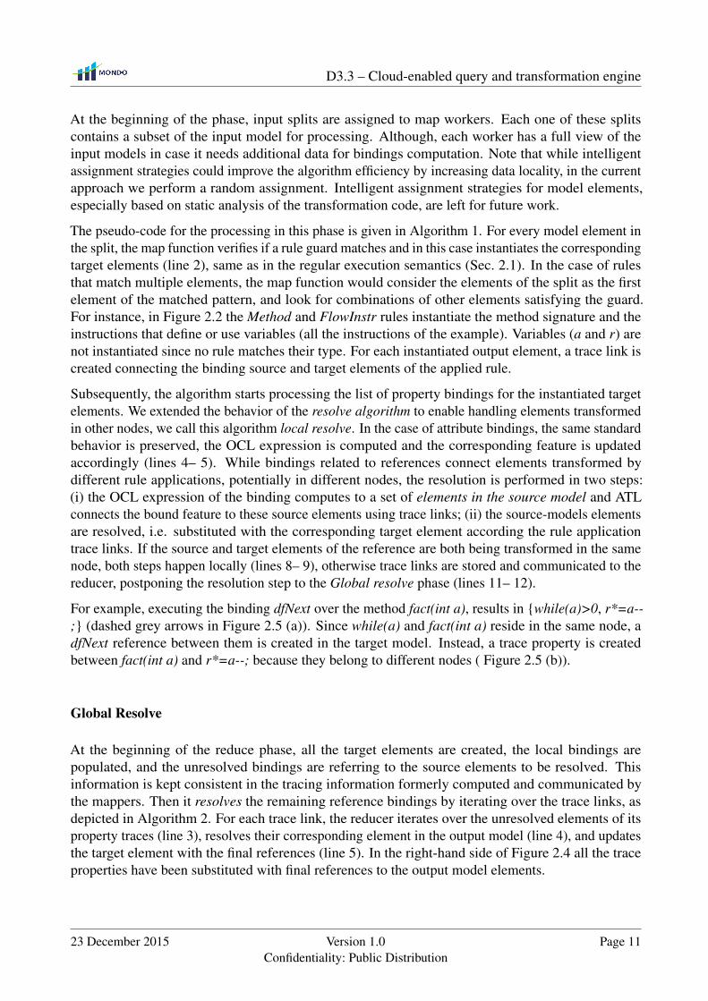
Figure 2.5: Local resolve of dfNext for {int fact (int a)}
communicates the set of model elements it created to the reduce phase, together with trace information.These trace links (grey arrows in Figure 2.4) encode the additional information that will be needed toresolve the binding, i.e. identify the exact target element that has to be referenced based on the tracinginformation. The reduce worker is responsible of gathering partial models and trace links from themap workers, and updating properties value of unresolved bindings. We call this phase Global resolve.
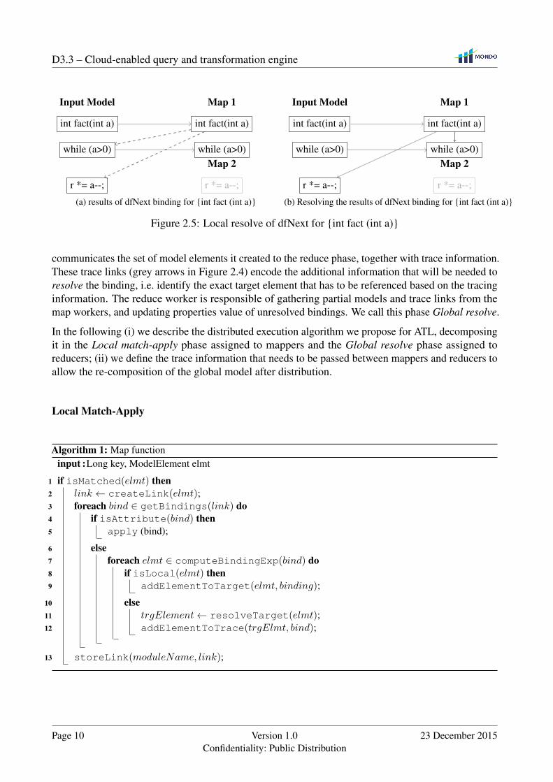
In the following (i) we describe the distributed execution algorithm we propose for ATL, decomposingit in the Local match-apply phase assigned to mappers and the Global resolve phase assigned toreducers; (ii) we define the trace information that needs to be passed between mappers and reducers toallow the re-composition of the global model after distribution.
Local Match-Apply
Algorithm 1: Map functioninput :Long key, ModelElement elmt
1 if isMatched(elmt) then2 link ← createLink(elmt);3 foreach bind ∈ getBindings(link) do4 if isAttribute(bind) then5 apply (bind);
6 else7 foreach elmt ∈ computeBindingExp(bind) do8 if isLocal(elmt) then9 addElementToTarget(elmt, binding);
10 else11 trgElement← resolveTarget(elmt);12 addElementToTrace(trgElmt, bind);
13 storeLink(moduleName, link);
Page 10 Version 1.0Confidentiality: Public Distribution
23 December 2015
D3.3 – Cloud-enabled query and transformation engine
At the beginning of the phase, input splits are assigned to map workers. Each one of these splitscontains a subset of the input model for processing. Although, each worker has a full view of theinput models in case it needs additional data for bindings computation. Note that while intelligentassignment strategies could improve the algorithm efficiency by increasing data locality, in the currentapproach we perform a random assignment. Intelligent assignment strategies for model elements,especially based on static analysis of the transformation code, are left for future work.
The pseudo-code for the processing in this phase is given in Algorithm 1. For every model element inthe split, the map function verifies if a rule guard matches and in this case instantiates the correspondingtarget elements (line 2), same as in the regular execution semantics (Sec. 2.1). In the case of rulesthat match multiple elements, the map function would consider the elements of the split as the firstelement of the matched pattern, and look for combinations of other elements satisfying the guard.For instance, in Figure 2.2 the Method and FlowInstr rules instantiate the method signature and theinstructions that define or use variables (all the instructions of the example). Variables (a and r) arenot instantiated since no rule matches their type. For each instantiated output element, a trace link iscreated connecting the binding source and target elements of the applied rule.
Subsequently, the algorithm starts processing the list of property bindings for the instantiated targetelements. We extended the behavior of the resolve algorithm to enable handling elements transformedin other nodes, we call this algorithm local resolve. In the case of attribute bindings, the same standardbehavior is preserved, the OCL expression is computed and the corresponding feature is updatedaccordingly (lines 4– 5). While bindings related to references connect elements transformed bydifferent rule applications, potentially in different nodes, the resolution is performed in two steps:(i) the OCL expression of the binding computes to a set of elements in the source model and ATLconnects the bound feature to these source elements using trace links; (ii) the source-models elementsare resolved, i.e. substituted with the corresponding target element according the rule applicationtrace links. If the source and target elements of the reference are both being transformed in the samenode, both steps happen locally (lines 8– 9), otherwise trace links are stored and communicated to thereducer, postponing the resolution step to the Global resolve phase (lines 11– 12).
For example, executing the binding dfNext over the method fact(int a), results in {while(a)>0, r*=a--;} (dashed grey arrows in Figure 2.5 (a)). Since while(a) and fact(int a) reside in the same node, adfNext reference between them is created in the target model. Instead, a trace property is createdbetween fact(int a) and r*=a--; because they belong to different nodes ( Figure 2.5 (b)).
Global Resolve
At the beginning of the reduce phase, all the target elements are created, the local bindings arepopulated, and the unresolved bindings are referring to the source elements to be resolved. Thisinformation is kept consistent in the tracing information formerly computed and communicated bythe mappers. Then it resolves the remaining reference bindings by iterating over the trace links, asdepicted in Algorithm 2. For each trace link, the reducer iterates over the unresolved elements of itsproperty traces (line 3), resolves their corresponding element in the output model (line 4), and updatesthe target element with the final references (line 5). In the right-hand side of Figure 2.4 all the traceproperties have been substituted with final references to the output model elements.
23 December 2015 Version 1.0Confidentiality: Public Distribution
Page 11
D3.3 – Cloud-enabled query and transformation engine
Algorithm 2: Reduce functioninput :String key, Set<TraceLink> links
1 foreach link ∈ links do2 foreach prop ∈ getTraceProperties(link) do // unresolved properties3 foreach elmt ∈ getSourceElements(prop) do4 trgElmt← resolveTarget(elmt);5 updateUnresolvedElement(prop, trgElmt);
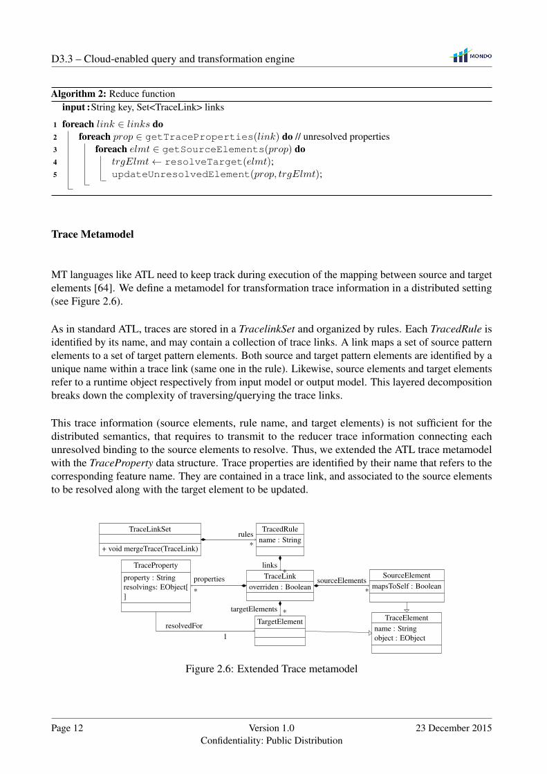
Trace Metamodel
MT languages like ATL need to keep track during execution of the mapping between source and targetelements [64]. We define a metamodel for transformation trace information in a distributed setting(see Figure 2.6).
As in standard ATL, traces are stored in a TracelinkSet and organized by rules. Each TracedRule isidentified by its name, and may contain a collection of trace links. A link maps a set of source patternelements to a set of target pattern elements. Both source and target pattern elements are identified by aunique name within a trace link (same one in the rule). Likewise, source elements and target elementsrefer to a runtime object respectively from input model or output model. This layered decompositionbreaks down the complexity of traversing/querying the trace links.
This trace information (source elements, rule name, and target elements) is not sufficient for thedistributed semantics, that requires to transmit to the reducer trace information connecting eachunresolved binding to the source elements to resolve. Thus, we extended the ATL trace metamodelwith the TraceProperty data structure. Trace properties are identified by their name that refers to thecorresponding feature name. They are contained in a trace link, and associated to the source elementsto be resolved along with the target element to be updated.
TracedRulename : String
TraceLinkSet
+ void mergeTrace(TraceLink)
TraceLinkoverriden : Boolean
TargetElement
SourceElementmapsToSelf : Boolean
TraceElementname : Stringobject : EObject
TraceProperty
property : Stringresolvings: EObject[]
rules*
links*
sourceElements*
targetElements *
properties
*
resolvedFor1
Figure 2.6: Extended Trace metamodel
Page 12 Version 1.0Confidentiality: Public Distribution
23 December 2015
D3.3 – Cloud-enabled query and transformation engine
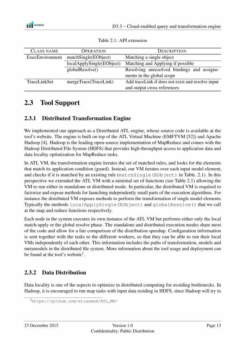
Table 2.1: API extension
CLASS NAME OPERATION DESCRIPTION
ExecEnvironment matchSingle(EObject) Matching a single objectlocalApplySingle(EObject) Matching and Applying if possibleglobalResolve() Resolving unresolved bindings and assigne-
ments in the global scopeTraceLinkSet mergeTrace(TraceLink) Add traceLink if does not exist and resolve input
and output cross references
2.3 Tool Support
2.3.1 Distributed Transformation Engine
We implemented our approach as a Distributed ATL engine, whose source code is available at thetool’s website. The engine is built on top of the ATL Virtual Machine (EMFTVM [52]) and ApacheHadoop [4]. Hadoop is the leading open-source implementation of MapReduce and comes with theHadoop Distributed File System (HDFS) that provides high-throughput access to application data anddata locality optimization for MapReduce tasks.
In ATL VM, the transformation engine iterates the set of matched rules, and looks for the elementsthat match its application condition (guard). Instead, our VM iterates over each input model element,and checks if it is matched by an existing rule (matchSingle(EObject) in Table. 2.1). In thisperspective we extended the ATL VM with a minimal set of functions (see Table 2.1) allowing theVM to run either in standalone or distributed mode. In particular, the distributed VM is required tofactorize and expose methods for launching independently small parts of the execution algorithms. Forinstance the distributed VM exposes methods to perform the transformation of single model elements.Typically the methods localApplySingle(EObject) and globalResolve() that we callat the map and reduce functions respectively.
Each node in the system executes its own instance of the ATL VM but performs either only the localmatch-apply or the global resolve phase. The standalone and distributed execution modes share mostof the code and allow for a fair comparison of the distribution speedup. Configuration informationis sent together with the tasks to the different workers, so that they can be able to run their localVMs independently of each other. This information includes the paths of transformation, models andmetamodels in the distributed file system. More information about the tool usage and deployment canbe found at the tool’s website3.
2.3.2 Data Distribution
Data locality is one of the aspects to optimize in distributed computing for avoiding bottlenecks. InHadoop, it is encouraged to run map tasks with input data residing in HDFS, since Hadoop will try to
3https://github.com/atlanmod/ATL_MR/
23 December 2015 Version 1.0Confidentiality: Public Distribution
Page 13

D3.3 – Cloud-enabled query and transformation engine
assign tasks to nodes where data to be processed is stored. In Distributed ATL we make use of HDFSfor storing input and output models, metamodels and transformation code.
Each mapper is assigned a subset of model elements by the splitting process. In Distributed ATL wefirst produce a text file containing model elements URIs as plain strings, one per line. This file will besplitted in chunks by Hadoop. Hadoop provides several input format classes with specific splittingbehavior. In our implementation we use an NLineInputFormat, that allows to specify the exact numberof lines per split. Finally, the default record reader in Hadoop creates one record for each line of theinput file. As a consequence, every map function in Distributed ATL will be executing on a singlemodel element.
Choosing the right number of splits has significant impact on the global performance. Having manysplits means that the time taken to process each split will be small compared to the time to process thewhole input. On the other hand, if splits are too small, then the overhead of managing the splits andcreating map tasks for each one of them may dominate the total job execution time. In our case weobserved better results where the number of splits matches the number of available workers. In otherwords, while configuring Distributed ATL, the number of lines per split should be set to model size
available nodes.
2.3.3 Tool Limitations
Currently, our ATL VM supports only the default EMF serialization format XMI. This file-basedrepresentation faces many issues related to scalability. In particular, models stored in XMI need tobe fully loaded in memory, but more importantly, XMI does not support concurrent read/write. Thishampers our tool at two levels, first, all the nodes should load the whole model even though if they onlyneed a subset of it. This prevents us from transforming very big models that would fit in memory. Thesecond one concerns the reduce phase parallelization, and this is due to the fact that only one mappercan write to the output XMI file at once. In a recent work, we extended an existing persistence backendNeoEMF [21] with support for concurrent read/write [22] on top of Apache HBase [51]. NeoEMF isalso part of the WP5 (High-Performance Model Persistence Format), and presented in details in D5.6.NeoEMF is an extensible and transparent persistence layer for modeling tools designed to optimizeruntime performance and memory occupancy. In future work, we plan to couple it with our VM tosolve these two particular issues.
2.4 Experimental Evaluation
We evaluate the scalability of our proposal by comparing how the transformation of our runningexample performs in different test environments. The transformation covers a sufficient set ofdeclarative ATL constructs enabling the specification of a large group of MTs. It also contains aninteresting number of OCL operations, recursive helper’s call included.
We use as input different sets of models of diverse sizes. The original case study [26] alreadyincludes a set of input models for the benchmark. These models are reverse-engineered from a set ofautomatically generated Java programs, with sizes up to 12 000 lines of code. For our benchmark weused the same generation process but to stress scalability we produced larger models with sizes up to
Page 14 Version 1.0Confidentiality: Public Distribution
23 December 2015
D3.3 – Cloud-enabled query and transformation engine
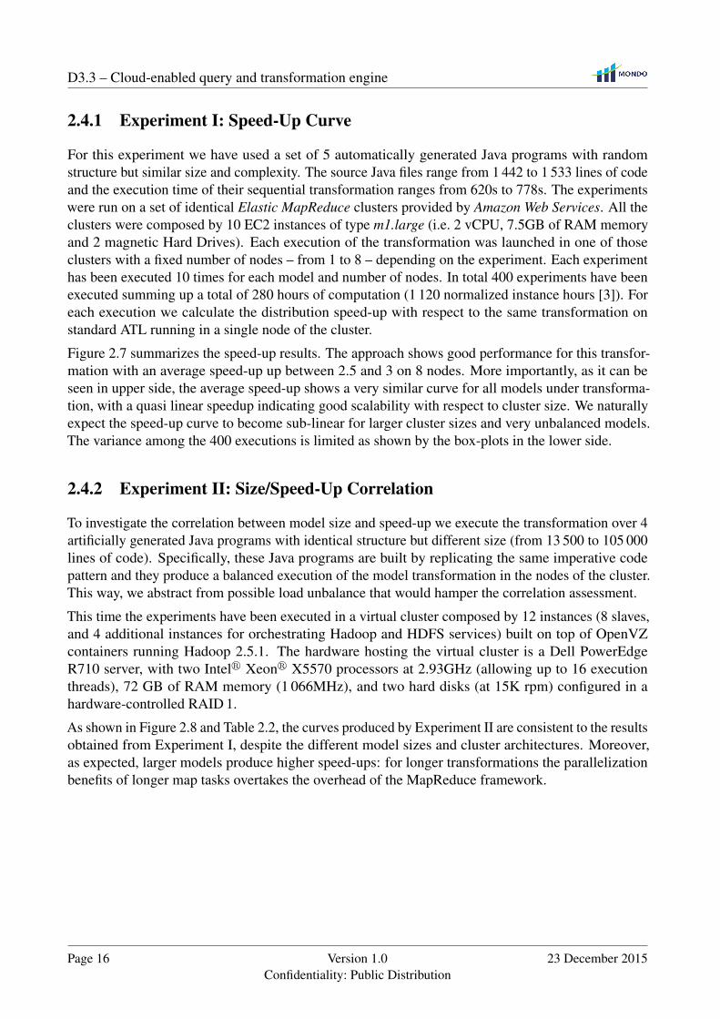
Table 2.2: Execution times and speed-up (between parentheses) per model
STD. Distributed VM using x nodes (time and speed-up)# SIZE ELTS VM 1 2 3 4 5 6 7 81 ∼4MB 20 706 244s 319s
(×0.8)165s(×1.5)
128s(×1.9)
107s(×2.3)
94s(×2.6)
84s(×2.9)
79s(×3.1)
75s(×3.3)
2 ∼8MB 41 406 1 005s 1 219s(×0.8)
596s(×1.7)
465s(×2.2)
350s(×2.9)
302s(×3.3)
259s(×3.9)
229s(×4.4)
199s(×5.1)
3 ∼16MB 82 806 4 241s 4 864s(×0.9)
2 318s(×1.8)
1 701s(×2.5)
1 332s(×3.2)
1 149s(×3.7)
945s(×4.5)
862s(×4.9)
717s(×5.9)
4 ∼32MB 161 006 14 705s 17 998s(×0.8)
8 712s(×1.7)
6 389s(×2.3)
5 016s(×2.9)
4 048s(×3.6)
3 564s(×4.1)
3 050s(×4.8)
2 642s(×5.6)
105 000 lines of code. We consider models of these sizes sufficient for benchmarking scalability inour use case: in our experimentation, processing in a single machine the largest of these models takesmore than four hours. All the models we generated and the experimentation results are available at thearticle website.
In what follows we demonstrate the scalability of our approach through two different but comple-mentary experimentations. The first one shows a quasi-linear speed-up with respect to the clustersize for input models with similar size, while the second one illustrates that the speed-up grows withincreasing model size.
1 2 3 4 5 6 7 8
0.51
1.52
2.53
3.54
Number of splits/nodes
× fasterAverage speed-up
1 2 3 4 5 6 7 8
0.5
1
1.5
2
2.5
3
Number of splits/nodes
× fasterAggregated speed-up variation
Model 1 Model 2 Model 3Model 4 Model 5
Figure 2.7: Speed-up obtained in Experiment I
23 December 2015 Version 1.0Confidentiality: Public Distribution
Page 15
D3.3 – Cloud-enabled query and transformation engine
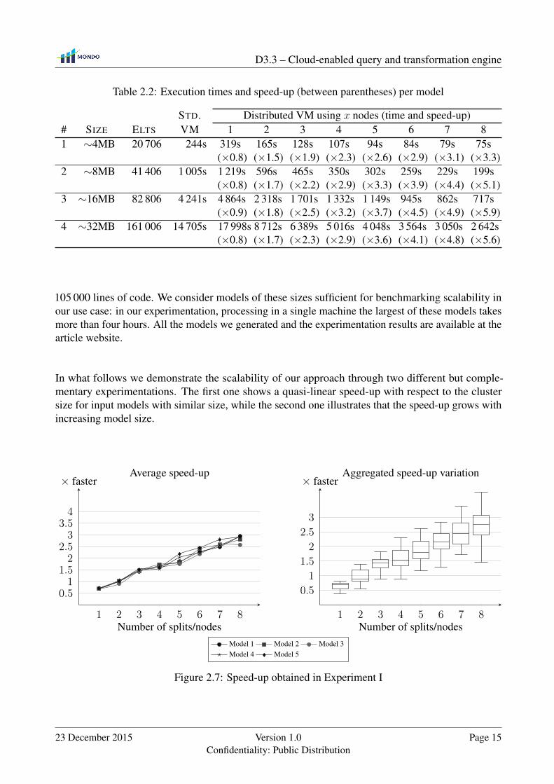
2.4.1 Experiment I: Speed-Up Curve
For this experiment we have used a set of 5 automatically generated Java programs with randomstructure but similar size and complexity. The source Java files range from 1 442 to 1 533 lines of codeand the execution time of their sequential transformation ranges from 620s to 778s. The experimentswere run on a set of identical Elastic MapReduce clusters provided by Amazon Web Services. All theclusters were composed by 10 EC2 instances of type m1.large (i.e. 2 vCPU, 7.5GB of RAM memoryand 2 magnetic Hard Drives). Each execution of the transformation was launched in one of thoseclusters with a fixed number of nodes – from 1 to 8 – depending on the experiment. Each experimenthas been executed 10 times for each model and number of nodes. In total 400 experiments have beenexecuted summing up a total of 280 hours of computation (1 120 normalized instance hours [3]). Foreach execution we calculate the distribution speed-up with respect to the same transformation onstandard ATL running in a single node of the cluster.
Figure 2.7 summarizes the speed-up results. The approach shows good performance for this transfor-mation with an average speed-up up between 2.5 and 3 on 8 nodes. More importantly, as it can beseen in upper side, the average speed-up shows a very similar curve for all models under transforma-tion, with a quasi linear speedup indicating good scalability with respect to cluster size. We naturallyexpect the speed-up curve to become sub-linear for larger cluster sizes and very unbalanced models.The variance among the 400 executions is limited as shown by the box-plots in the lower side.
2.4.2 Experiment II: Size/Speed-Up Correlation
To investigate the correlation between model size and speed-up we execute the transformation over 4artificially generated Java programs with identical structure but different size (from 13 500 to 105 000lines of code). Specifically, these Java programs are built by replicating the same imperative codepattern and they produce a balanced execution of the model transformation in the nodes of the cluster.This way, we abstract from possible load unbalance that would hamper the correlation assessment.
This time the experiments have been executed in a virtual cluster composed by 12 instances (8 slaves,and 4 additional instances for orchestrating Hadoop and HDFS services) built on top of OpenVZcontainers running Hadoop 2.5.1. The hardware hosting the virtual cluster is a Dell PowerEdgeR710 server, with two Intelr Xeonr X5570 processors at 2.93GHz (allowing up to 16 executionthreads), 72 GB of RAM memory (1 066MHz), and two hard disks (at 15K rpm) configured in ahardware-controlled RAID 1.
As shown in Figure 2.8 and Table 2.2, the curves produced by Experiment II are consistent to the resultsobtained from Experiment I, despite the different model sizes and cluster architectures. Moreover,as expected, larger models produce higher speed-ups: for longer transformations the parallelizationbenefits of longer map tasks overtakes the overhead of the MapReduce framework.
Page 16 Version 1.0Confidentiality: Public Distribution
23 December 2015

D3.3 – Cloud-enabled query and transformation engine
1 2 3 4 5 6 7 8
102
103
104
Number of splits/nodes
s Execution time
1 2 3 4 5 6 7 8
0
2
4
6
Number of splits/nodes
× faster Speed-up
Model 1 (∼4MB) Model 2 (∼8MB)Model 3 (∼16MB) Model 4 (∼32MB)
Figure 2.8: Execution times and speed-up on Experiment II
23 December 2015 Version 1.0Confidentiality: Public Distribution
Page 17
Chapter 3
INCQUERY-D
In the previous chapter we proposed a solution for distributing batch transformations, that computea full target model at each execution. However in several practical scenarios the source model of aquery/transformation evolves in time. In these cases, recomputing a full result at each change of thesource would not be judicious. Incremental evaluation of model queries aims to reduce query executiontime by limiting the impact of model modifications to query result calculation. Such algorithms workby either (i) building a cache of interim query results and keeping it up-to-date as models change(e.g. EMF-INCQUERY [8]) or (ii) applying impact analysis techniques and reevaluating queriesonly in contexts that are affected by a change [20, 47]. This technique has been proven to improveperformance dramatically in several scenarios (e.g. on-the-fly well-formedness validation or modelsynchronization), at the cost of increasing memory consumption. Unfortunately, this overhead iscombined with the increase in model sizes due to in-memory representation (found in state-of-the-artframeworks such as EMF [53]). Since single-computer heaps cannot grow arbitrarily (as executiontimes degrade drastically due to garbage collection problems), memory consumption is the mostsignificant scalability limitation.
An alternative approach to tackling MDE scalability issues is to make use of advances in persistencetechnology. As the majority of model-based tools uses a graph-oriented data model, recent results ofthe NoSQL and Linked Data movement [43, 1, 2] are straightforward candidates for adaptation to MDEpurposes (as experimented e.g. in Morsa [17] or Neo4EMF [5]). Unfortunately, this idea poses difficultconceptual and technological challenges as property graph databases lack strong metamodeling supportand their query features are simplistic compared to MDE needs [29]. Additionally, the underlyingdata representation format of semantic databases (RDF [23]) has crucial conceptual and technologicaldifferences to traditional metamodeling languages such as Ecore [53]. Additionally, while there areinitial efforts to overcome the mapping issues between the MDE and Linked Data worlds [25], eventhe most sophisticated NoSQL storage technologies lack efficient and mature support for executingexpressive queries incrementally.
We aim to address these challenges by proposing a novel architecture for a distributed and incrementalmodel query framework by adapting incremental graph pattern matching techniques to a distributedcloud based infrastructure. A main contribution of our novel architecture is that the distributedstorage of data is completely separated from the distributed handling of indexing and query evaluation.Therefore, caching the result sets of queries in a distributed fashion provides a way to scale out the
18
D3.3 – Cloud-enabled query and transformation engine
Route
Segment
length : EInt
SensorSignal
actualState : SignalStateKind
Switch
actualState : SwitchStateKind
SwitchPosition
switchState : SwitchStateKindTrackElement
SwitchStateKind
FAILURE
LEFT
RIGHT
STRAIGHT
SignalStateKind
STOP
FAILURE
GO
1 + route
* + switchPosition
2..*+ routeDefinition
1 + exit
1 + entry
*+ sensor
*+ trackElement
*
+ connectsTo
* + switchPosition
1 + switch
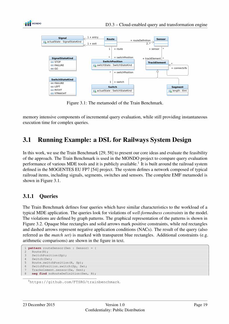
Figure 3.1: The metamodel of the Train Benchmark.
memory intensive components of incremental query evaluation, while still providing instantaneousexecution time for complex queries.
3.1 Running Example: a DSL for Railways System Design
In this work, we use the Train Benchmark [29, 58] to present our core ideas and evaluate the feasibilityof the approach. The Train Benchmark is used in the MONDO project to compare query evaluationperformance of various MDE tools and it is publicly available.1 It is built around the railroad systemdefined in the MOGENTES EU FP7 [54] project. The system defines a network composed of typicalrailroad items, including signals, segments, switches and sensors. The complete EMF metamodel isshown in Figure 3.1.
3.1.1 Queries
The Train Benchmark defines four queries which have similar characteristics to the workload of atypical MDE application. The queries look for violations of well-formedness constraints in the model.The violations are defined by graph patterns. The graphical representation of the patterns is shown inFigure 3.2. Opaque blue rectangles and solid arrows mark positive constraints, while red rectanglesand dashed arrows represent negative application conditions (NACs). The result of the query (alsoreferred as the match set) is marked with transparent blue rectangles. Additional constraints (e.g.arithmetic comparisons) are shown in the figure in text.� �1 pattern routeSensor(Sen : Sensor) = {2 Route(R);3 SwitchPosition(Sp);4 Switch(Sw);5 Route.switchPosition(R, Sp);6 SwitchPosition.switch(Sp, Sw);7 Trackelement.sensor(Sw, Sen);8 neg find noRouteDefinition(Sen, R);
1https://github.com/FTSRG/trainbenchmark.
23 December 2015 Version 1.0Confidentiality: Public Distribution
Page 19
D3.3 – Cloud-enabled query and transformation engine
segment: Segment
segment.length 0
(a) PosLength
sensor
switch: Switch
sensor: Sensor
(b) SwitchSensor
sensorrouteDefinition switch
switchPosition
switch: Switch
sp: SwitchPositionroute: Route
sensor: Sensor
(c) RouteSensor
connectsTo
routeDefinition
exit
sensor sensor
routeDefinition
routeDefinition
entry
route1 != route3
te1: TrackElement
sensor1: Sensor
route1: Route
signal: Signal
te2: TrackElement
sensor2: Sensor
route3: Route
route2: Route
(d) SignalNeighbor
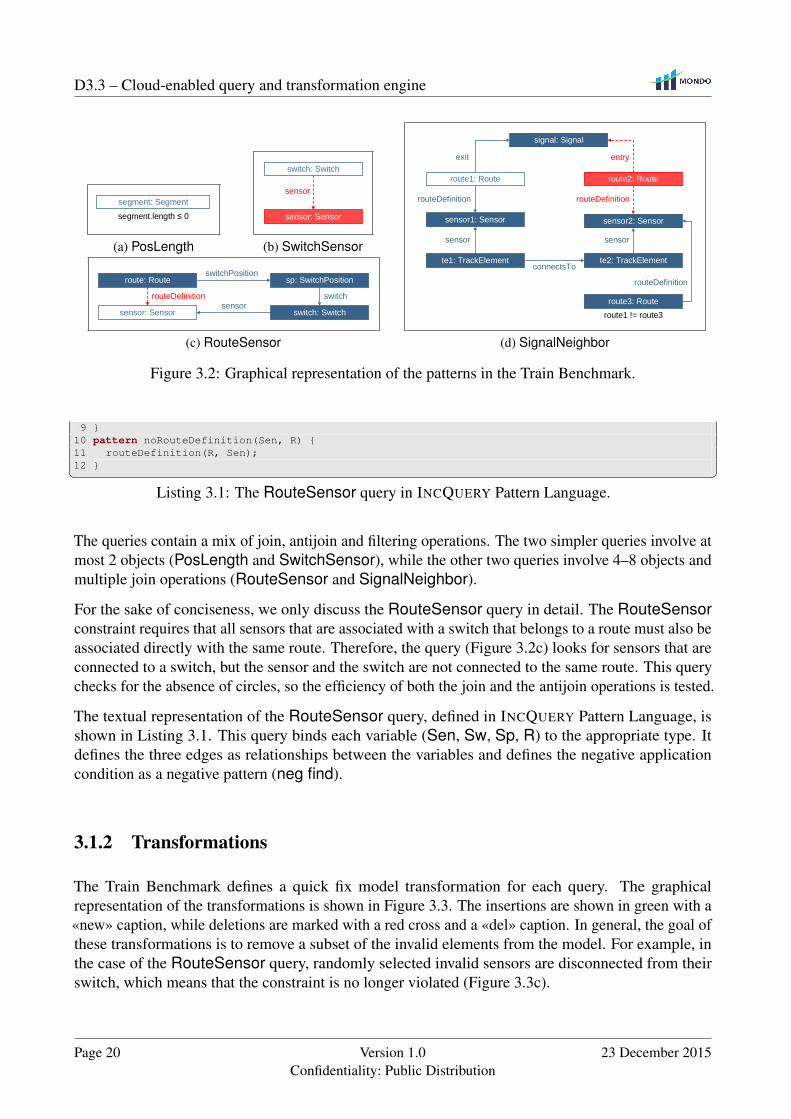
Figure 3.2: Graphical representation of the patterns in the Train Benchmark.
9 }10 pattern noRouteDefinition(Sen, R) {11 routeDefinition(R, Sen);12 }� �
Listing 3.1: The RouteSensor query in INCQUERY Pattern Language.
The queries contain a mix of join, antijoin and filtering operations. The two simpler queries involve atmost 2 objects (PosLength and SwitchSensor), while the other two queries involve 4–8 objects andmultiple join operations (RouteSensor and SignalNeighbor).
For the sake of conciseness, we only discuss the RouteSensor query in detail. The RouteSensorconstraint requires that all sensors that are associated with a switch that belongs to a route must also beassociated directly with the same route. Therefore, the query (Figure 3.2c) looks for sensors that areconnected to a switch, but the sensor and the switch are not connected to the same route. This querychecks for the absence of circles, so the efficiency of both the join and the antijoin operations is tested.
The textual representation of the RouteSensor query, defined in INCQUERY Pattern Language, isshown in Listing 3.1. This query binds each variable (Sen, Sw, Sp, R) to the appropriate type. Itdefines the three edges as relationships between the variables and defines the negative applicationcondition as a negative pattern (neg find).
3.1.2 Transformations
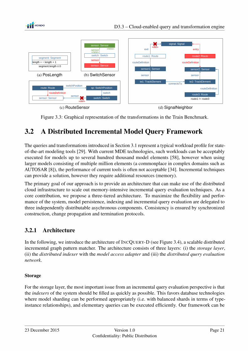
The Train Benchmark defines a quick fix model transformation for each query. The graphicalrepresentation of the transformations is shown in Figure 3.3. The insertions are shown in green with a«new» caption, while deletions are marked with a red cross and a «del» caption. In general, the goal ofthese transformations is to remove a subset of the invalid elements from the model. For example, inthe case of the RouteSensor query, randomly selected invalid sensors are disconnected from theirswitch, which means that the constraint is no longer violated (Figure 3.3c).
Page 20 Version 1.0Confidentiality: Public Distribution
23 December 2015
D3.3 – Cloud-enabled query and transformation engine
length = length + 1
segment.length 0
segment: Segment
(a) PosLength
sensor
sensor: Sensor
sensor: Sensor
sensor«new»
«new»
switch: Switch
(b) SwitchSensor
sensorrouteDefinition switch
switchPosition
switch: Switch
sp: SwitchPositionroute: Route
sensor: Sensor«del»
(c) RouteSensor
connectsTo
routeDefinition
exit
sensor sensor
routeDefinition
routeDefinition
entry
route1 != route3
te1: TrackElement
sensor1: Sensor
route1: Route
signal: Signal
te2: TrackElement
sensor2: Sensor
route3: Route
route2: Route
«del»
(d) SignalNeighbor
Figure 3.3: Graphical representation of the transformations in the Train Benchmark.
3.2 A Distributed Incremental Model Query Framework
The queries and transformations introduced in Section 3.1 represent a typical workload profile for state-of-the-art modeling tools [29]. With current MDE technologies, such workloads can be acceptablyexecuted for models up to several hundred thousand model elements [58], however when usinglarger models consisting of multiple million elements (a commonplace in complex domains such asAUTOSAR [8]), the performance of current tools is often not acceptable [34]. Incremental techniquescan provide a solution, however they require additional resources (memory).
The primary goal of our approach is to provide an architecture that can make use of the distributedcloud infrastructure to scale out memory-intensive incremental query evaluation techniques. As acore contribution, we propose a three-tiered architecture. To maximize the flexibility and perfor-mance of the system, model persistence, indexing and incremental query evaluation are delegated tothree independently distributable asychronous components. Consistency is ensured by synchronizedconstruction, change propagation and termination protocols.
3.2.1 Architecture
In the following, we introduce the architecture of INCQUERY-D (see Figure 3.4), a scalable distributedincremental graph pattern matcher. The architecture consists of three layers: (i) the storage layer,(ii) the distributed indexer with the model access adapter and (iii) the distributed query evaluationnetwork.
Storage
For the storage layer, the most important issue from an incremental query evaluation perspective is thatthe indexers of the system should be filled as quickly as possible. This favors database technologieswhere model sharding can be performed appropriately (i.e. with balanced shards in terms of type-instance relationships), and elementary queries can be executed efficiently. Our framework can be
23 December 2015 Version 1.0Confidentiality: Public Distribution
Page 21

D3.3 – Cloud-enabled query and transformation engine
Server 0
Database
shard 0
Transaction
Server 1
Database
shard 1
Server 2
Database
shard 2
Server 3
Database
shard 3
Distributed query evaluation network
Notifications3
Results
1
Model
manipulationElementary queries
and modifications2
4
Distributed indexer Model access adapter
Figure 3.4: The architecture of INCQUERY-D, an incremental query framework(deployed in a sample four-node cluster configuration).
adapted to fundamentally different storage back-ends, including triple stores, graph databases andrelational database managements systems.
Model Access Adapter
In contrast to a traditional setup where the distributed model repository is accessed on a per-node basisby a model manipulation transaction, INCQUERY-D provides a model access adapter that offers threecore services:
1. The primary task is to provide a surrogate key mechanism so that each model element in theentire distributed repository can be uniquely identified and located within storage shards.
2. The model access adapter provides a graph-like data manipulation API ( 1© in Figure 3.4) tothe user. The model access adapter translates the operations issued by the user to the querylanguage of the backend and forwards it to the underlying data storage.
3. Change notifications are required by incremental query evaluation, thus model changes arecaptured and their effects are propagated in the form of notification objects ( 3© in Figure 3.4).The notifications generate update messages that keep the state of the query evaluation networkconsistent with the model. While relational databases usually provide triggers for generatingnotifications, most triplestores and graph databases lack this feature. Due to the lack of generalsupport, notifications are controlled by the model access adapter by providing a façade for allmodel manipulation operations.
Page 22 Version 1.0Confidentiality: Public Distribution
23 December 2015
D3.3 – Cloud-enabled query and transformation engine
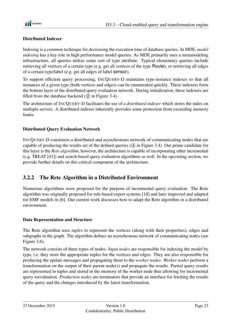
Distributed Indexer
Indexing is a common technique for decreasing the execution time of database queries. In MDE, modelindexing has a key role in high performance model queries. As MDE primarily uses a metamodelinginfrastructure, all queries utilize some sort of type attribute. Typical elementary queries includeretrieving all vertices of a certain type (e.g. get all vertices of the type Route), or retrieving all edgesof a certain type/label (e.g. get all edges of label sensor).
To support efficient query processing, INCQUERY-D maintains type-instance indexes so that allinstances of a given type (both vertices and edges) can be enumerated quickly. These indexers formthe bottom layer of the distributed query evaluation network. During initialization, these indexers arefilled from the database backend ( 2© in Figure 3.4).
The architecture of INCQUERY-D facilitates the use of a distributed indexer which stores the index onmultiple servers. A distributed indexer inherently provides some protection from exceeding memorylimits.
Distributed Query Evaluation Network
INCQUERY-D constructs a distributed and asynchronous network of communicating nodes that arecapable of producing the results set of the defined queries ( 4© in Figure 3.4). Our prime candidate forthis layer is the Rete algorithm, however, the architecture is capable of incorporating other incremental(e.g. TREAT [41]) and search-based query evaluation algorithms as well. In the upcoming section, weprovide further details on this critical component of the architecture.
3.2.2 The Rete Algorithm in a Distributed Environment
Numerous algorithms were proposed for the purpose of incremental query evaluation. The Retealgorithm was originally proposed for rule-based expert systems [18] and later improved and adaptedfor EMF models in [6]. Our current work discusses how to adapt the Rete algorithm in a distributedenvironment.
Data Representation and Structure
The Rete algorithm uses tuples to represent the vertices (along with their properties), edges andsubgraphs in the graph. The algorithm defines an asynchronous network of communicating nodes (seeFigure 3.6).
The network consists of three types of nodes. Input nodes are responsible for indexing the model bytype, i.e. they store the appropriate tuples for the vertices and edges. They are also responsible forproducing the update messages and propagating them to the worker nodes. Worker nodes perform atransformation on the output of their parent node(s) and propagate the results. Partial query resultsare represented in tuples and stored in the memory of the worker node thus allowing for incrementalquery reevaluation. Production nodes are terminators that provide an interface for fetching the resultsof the query and the changes introduced by the latest transformation.
23 December 2015 Version 1.0Confidentiality: Public Distribution
Page 23

D3.3 – Cloud-enabled query and transformation engine
1 2 3 4
Serialized
model
Metamodel
specification
Query
specification
9
Construct Rete
Database
shards
Load model,
initialize Rete
Maintain
query resultsEvaluate queryDeploy Rete
Model access
adapterClient
6
7
5
8
Figure 3.5: The operational workflow of the distributed Rete algorithm.
Construction
The system constructs the Rete network from the layout derived from the query specification. Theconstruction algorithm may apply various optimization techniques, e.g. reusing existing Rete nodes,known as node sharing [6]. An efficient Rete construction algorithm is discussed in detail in [60].
In a distributed environment, the construction of the Rete network introduces additional challenges.First, the system must keep track of the resources available in the server cluster and maintain themapping between the Rete nodes and the servers accordingly. Second, the Rete nodes need to beaware of the current infrastructure mapping so they can send their messages to the appropriate servers.In our system, the Rete nodes are remotely instantiated by the coordinator node. The coordinator nodethen sends the infrastructure mapping of the Rete network to all nodes. This way, each node is capableof subscribing to the update messages of its parent node(s). The coordinator also starts the operationsin the network, such as loading the model, initiating transformations and retrieving the query results.
Operation
The operational workflow of INCQUERY-D is shown in Figure 3.5. Based on the metamodel and thequery specification, INCQUERY-D first constructs a Rete network 1© and deploys it 2©. In the nextstep, it loads the model 3© and traverses it to initialize the indexers of the Rete network. The Retenetwork evaluates the query by processing the incoming tuples 4©. Because both the Rete indexersand the database shards are distributed across the cluster, loading the model and initializing the Retenetwork needs network communication. The client is able to retrieve the results 5©– 6©, modify themodel and reevaluate the query 7©– 9©.
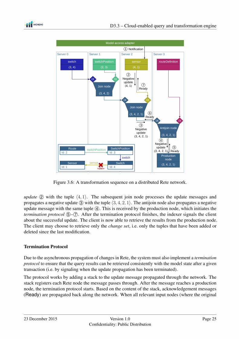
The modifications are propagated in the form of update messages (also known as deltas). Creating newgraph elements (vertices or edges) results in positive update messages, while removing graph elementsresults in negative update messages. The operation of the network is illustrated on the instance graphdepicted in the lower left corner of Figure 3.6. This graph violates the well-formedness constaintdefined by the RouteSensor query, hence the tuple 〈3, 4, 2, 1〉 appears in the result set of the query.The figure also shows the Rete network containing partial matches of the original graph.
To resolve the violation, we apply the quick fix transformation defined in the Train Benchmarkand delete the sensor edge between vertices 4 and 1. When the edge is deleted, the sensor typeindexer (an input node) receives a notification from the model access adapter 1© and sends a negative
Page 24 Version 1.0Confidentiality: Public Distribution
23 December 2015
D3.3 – Cloud-enabled query and transformation engine
Server 0 Server 1 Server 2 Server 3
switch routeDefinitionsensorswitchPosition
Join node
Production
node
Join node
Antijoin node
3, 4 2, 3 4, 1
3, 4, 2
3, 4, 2, 1
3, 4, 2, 1
Negative
update
3, 4, 2, 1
Negative
update
4, 1
Ready
Ready
5
4
2
7
IX IX
IX IX
IX IX
Negative
update
3, 4, 2, 1
3
Ready
6
3, 4, 2, 1 sensor
switch
switchPositionRoute
Id: 2
SwitchPosition
Id: 3
Switch
Id: 4
Sensor
Id: 1«del»
Model access adapter
Notification1
Figure 3.6: A transformation sequence on a distributed Rete network.
update 2© with the tuple 〈4, 1〉. The subsequent join node processes the update messages andpropagates a negative update 3© with the tuple 〈3, 4, 2, 1〉. The antijoin node also propagates a negativeupdate message with the same tuple 4©. This is received by the production node, which initiates thetermination protocol 5©– 7©. After the termination protocol finishes, the indexer signals the clientabout the successful update. The client is now able to retrieve the results from the production node.The client may choose to retrieve only the change set, i.e. only the tuples that have been added ordeleted since the last modification.
Termination Protocol
Due to the asynchronous propagation of changes in Rete, the system must also implement a terminationprotocol to ensure that the query results can be retrieved consistently with the model state after a giventransaction (i.e. by signaling when the update propagation has been terminated).
The protocol works by adding a stack to the update message propagated through the network. Thestack registers each Rete node the message passes through. After the message reaches a productionnode, the termination protocol starts. Based on the content of the stack, acknowledgement messages(Ready) are propagated back along the network. When all relevant input nodes (where the original
23 December 2015 Version 1.0Confidentiality: Public Distribution
Page 25

D3.3 – Cloud-enabled query and transformation engine
update message(s) started from) receive the acknowledge messages, the termination protocol finishes.The operation of the termination protocol can be observed in Figure 3.6 (messages 5©– 7©).
3.3 Evaluation
To evaluate the feasibility and performance of the INCQUERY-D approach, we created a distributedbenchmark environment. We implemented a prototype of INCQUERY-D and compared its performanceto a state-of-the-art non-incremental SPARQL query engine of a (distributed) RDF store.
3.3.1 Benchmark Scenario
In order to measure the efficiency of model queries and manipulation operations over the distributedarchitecture, we adapted the Train Benchmark [29, 58] (dintroduced in Section 3.1) to a distributedenvironment. The main goal of the Train Benchmark is to measure the query reevaluation times insystems operating on a graph-like data set. The benchmark targets a “real-world” MDE workload byrunning a specific set of queries (Section 3.1.1) and transformations on the model (Section 3.1.2). Inthis workload profile, the system runs either a single query or a single transformation at a time, asquickly as possible.
To assess scalability, the benchmark uses instance models of growing sizes, each model containingtwice as many model elements as the previous one. Scalability is also evaluated against queries ofdifferent complexity. For a successful run, the tested tool is expected to evaluate the query and returnthe identifiers of the model elements in the result set.
Execution Phases
The benchmark transaction sequence consists of four distinct phases. The serialization of the modelis loaded into the database (load); a well-formedness query is executed on the model (initial valida-tion); some elements are programmatically modified (transformation) and the query is reevaluated(revalidation).
Instance Models
We developed a generator that creates instance models. The instance models are generated pseudoran-domly, with pre-defined structural constraints and a regular fan-out structure (i.e. the in-degree andout-degree of the vertices follow a uniform distribution) [29].
Transformations
In the transformation phase, the benchmark runs quick fix transformations (Section 3.1.2) on 10% ofthe invalid elements (the result set of the initial validation phase), except for the SignalNeighborquery, where 1/3 of the invalid elements are modified. The transformations run in a single logicaltransaction, implemented with multiple physical transactions.
Page 26 Version 1.0Confidentiality: Public Distribution
23 December 2015
D3.3 – Cloud-enabled query and transformation engine
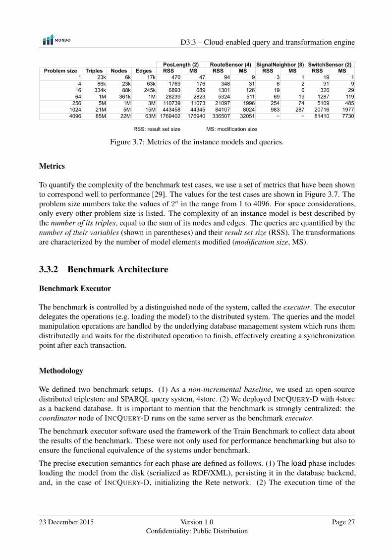
PosLength (2) RouteSensor (4) SignalNeighbor (8) SwitchSensor (2)Problem size Triples Nodes Edges RSS MS RSS MS RSS MS RSS MS
1 23k 6k 17k 470 47 94 9 3 1 19 14 86k 23k 63k 1769 176 348 31 6 2 91 9
16 334k 88k 245k 6893 689 1301 126 19 6 326 2964 1M 361k 1M 28239 2823 5324 511 69 19 1287 119
256 5M 1M 3M 110739 11073 21097 1996 254 74 5109 4851024 21M 5M 15M 443458 44345 84107 8024 983 287 20716 19774096 85M 22M 63M 1769402 176940 336507 32051 − − 81410 7730
RSS: result set size MS: modification size
Figure 3.7: Metrics of the instance models and queries.
Metrics
To quantify the complexity of the benchmark test cases, we use a set of metrics that have been shownto correspond well to performance [29]. The values for the test cases are shown in Figure 3.7. Theproblem size numbers take the values of 2n in the range from 1 to 4096. For space considerations,only every other problem size is listed. The complexity of an instance model is best described bythe number of its triples, equal to the sum of its nodes and edges. The queries are quantified by thenumber of their variables (shown in parentheses) and their result set size (RSS). The transformationsare characterized by the number of model elements modified (modification size, MS).
3.3.2 Benchmark Architecture
Benchmark Executor
The benchmark is controlled by a distinguished node of the system, called the executor. The executordelegates the operations (e.g. loading the model) to the distributed system. The queries and the modelmanipulation operations are handled by the underlying database management system which runs themdistributedly and waits for the distributed operation to finish, effectively creating a synchronizationpoint after each transaction.
Methodology
We defined two benchmark setups. (1) As a non-incremental baseline, we used an open-sourcedistributed triplestore and SPARQL query system, 4store. (2) We deployed INCQUERY-D with 4storeas a backend database. It is important to mention that the benchmark is strongly centralized: thecoordinator node of INCQUERY-D runs on the same server as the benchmark executor.
The benchmark executor software used the framework of the Train Benchmark to collect data aboutthe results of the benchmark. These were not only used for performance benchmarking but also toensure the functional equivalence of the systems under benchmark.
The precise execution semantics for each phase are defined as follows. (1) The load phase includesloading the model from the disk (serialized as RDF/XML), persisting it in the database backend,and, in the case of INCQUERY-D, initializing the Rete network. (2) The execution time of the
23 December 2015 Version 1.0Confidentiality: Public Distribution
Page 27

D3.3 – Cloud-enabled query and transformation engine
initial validation phase is the time required for the first complete evaluation of the query. (3) Thetransformation phase starts with the selection of the invalid model elements and is finished after themodifications are persisted in the database backend. In the case of INCQUERY-D, the transformationis only finished after the Rete network has processed the changes and is in a consistent state. (4) Therevalidation phase re-runs the query of the initial validation phase, and retrieves the updated results.
The execution time includes the time required for the defined operation, the computation and I/Ooperations of the servers in the cluster and the network communication (to both directions). Theexecution times were determined using the System.nanoTime() Java method.
Environment
We used 4store [24] (version 1.1.5) as our storage backend. The servers ran the Ubuntu 12.10 64-bitoperating system with Oracle Java 7. For the implementation of the distributed Rete network, we usedAkka [57] (version 2.1.4), a distributed, asynchronous messaging system.
The system was deployed on the private cloud that runs on the Apache VCL (Virtual Computing Lab)platform. We reserved four virtual machines on separate host machines, with each using a quad-coreIntel Xeon L5420 CPU running at 2.5 GHz and having 16 GB of RAM. The host machines wereconnected to a dedicated gigabit Ethernet network.
3.3.3 Results
The benchmark results of our experiments are shown in Figure 3.8. On each plot, the x axis shows theproblem size, i.e. the size of the instance model, while the y axis shows the execution time of a certainphase, measured in seconds. Both axes use logarithmic scale.
First, we discuss the results for RouteSensor, a query of medium complexity. Figure 3.8a presents thecombined execution time for the load and initial validation phases. The execution time is a low orderpolynomial of the model size for both the standalone 4store and the INCQUERY-D system. The resultsshow that despite the initial overhead of the Rete network initialization, INCQUERY-D has a significantadvantage starting from medium-sized models (with approximately 1 million triples). Figure 3.8bshows the execution time for the sum of the transformation and revalidation phases. The results showthat the Rete maintenance overhead imposed by INCQUERY-D on model manipulation operations islow, and overall the model transformation phase when using INCQUERY-D is considerably faster formodels larger than a few hundred thousand triples. Figure 3.8c focuses on the revalidation phase.The performance of INCQUERY-D is characteristically different from that of the SPARQL engine of4store. Even for models with tens of millions of tuples, INCQUERY-D provides close to instantaneousquery re-evaluation.
Figure 3.8d–3.8f are presented to compare the results for the PosLength, the SignalNeighbor andthe SwitchSensor queries, respectively. The PosLength query uses only a few variables but has alarge result set. The SignalNeighbor query includes many variables but has a small match set. TheSwitchSensor query uses a few variables and has a medium-sized result set.
The large result set of the PosLength query (Figure 3.8d) is a challenge for incremental queryevaluation systems, however, INCQUERY-D still provides reasonably fast load, transformation and
Page 28 Version 1.0Confidentiality: Public Distribution
23 December 2015

D3.3 – Cloud-enabled query and transformation engine
Combined execution phases●●●
load+initial validation transformation+revalidation revalidation
Configuration4storeIncQuery-D
0.75
6.27
52.42
438.52
3668.00
1 4 16 64 256 1024 4096
Problem size
Exe
cutio
n tim
e [s
]
(a) Load and initial validation(RouteSensor)
●
●
●
●●
●●
●
●
●
●●
●
●
●
●●
●
●
●
●
●●
0.25
3.35
45.47
617.11
8376.00
1 4 16 64 256 1024 4096
Problem size
Exe
cu
tio
n t
ime
[s]
(b) Transformation and revalidation(RouteSensor)
0.02
0.34
7.28
157.28
3399.00
1 4 16 64 256 1024 4096
Problem size
Exe
cutio
n tim
e [s
]
(c) Revalidation (RouteSensor)
●●
●●
●●
●●
●
●●
●●
●●
●
●●
●●
●●
●●
0.06
0.76
10.07
133.61
1773.00
1 4 16 64 256 1024 4096
Problem size
Exe
cu
tio
n t
ime
[s]
(d) PosLength
●
●
●
●
●
●●●
●
●●●
●
●●●
●
●
●
●●●
0.01
0.14
3.82
108.27
3067.00
1 4 16 64 256 1024
Problem sizeE
xe
cu
tio
n t
ime
[s]
(e) SignalNeighbor
●
●●●
●●●●
●●●
●● ●
● ●
●●
●
●●●
●●
0.01
0.15
3.41
75.25
1660.00
1 4 16 64 256 1024 4096
Problem size
Exe
cu
tio
n t
ime
[s]
(f) SwitchSensor
Figure 3.8: Benchmark results
query evaluation times, while outperforming 4store on the revalidation time. The results for theSignalNeighbor query (Figure 3.8e) show INCQUERY-D has a characteristic advantage on both thetransformation and the revalidation times. The SwitchSensor query also shows a clear advantage ofINCQUERY-D for transformation and revalidation.
Summary of Observations
Based on the results, we can make the following observations. As expected, due to the overhead of theRete construction, the non-incremental approach is often faster for small models. However, even formedium-sized models (with a couple of million triples), the Rete construction overhead already paysoff for the initial validation. After the Rete network is initialized, INCQUERY-D provides significantlyimproved transformation and revalidation times, with the revalidation times being consistently ordersof magnitude faster due to the different characteristics of their execution time.
In summary, these observations show that INCQUERY-D is not just capable of processing modelswith over 10 million elements (pushing the limits well beyond the capabilities of single-workstationmodeling tools), but also, it provides close to instantaneous query evaluation times even for verycomplex queries.
23 December 2015 Version 1.0Confidentiality: Public Distribution
Page 29

D3.3 – Cloud-enabled query and transformation engine
Threats to Validity
To minimize internal threats to validity, we turned off the caching mechanisms of the operating systemto force rereading the serialized model from the disk. Additionally, to avoid the propagation of thewarmup effect of the Java Virtual Machine between the runs, each test case was started independentlyin a separate JVM.
As our cloud infrastructure was subject to minimal concurrent load during the measurements, weaimed to minize the distortion due to load transients by running the benchmark three times andtaking the minimum value for each phase into consideration. We did experience a certain deviation ofexecution times for smaller models (Figure 3.8f). However, for larger models (our most importanttarget), the transient effects do not influence validity of the benchmark results.
Regarding external validity, we used a benchmark that is a faithful representation of a workload profileof a modeling tool for large-scale models [29, 58]. The queries both for 4store and INCQUERY-D werevalidated by domain experts. We aimed to minimize the potential bias introduced by the additionaldegrees of freedom inherent in distributed systems, e.g. by a randomized manual allocation of theprocessing nodes of Rete network in the cloud. We plan to conduct a more detailed investigation ofthese effects as future work.
Page 30 Version 1.0Confidentiality: Public Distribution
23 December 2015
Chapter 4
Related Work
This chapter presentes the related work for distributed batch computation (Section 4.1) and distributedincremental query evaluation (Section 4.2).
4.1 Distributed Batch Computation
To our knowledge, the distributed ATL engine presented in Chapter 2 is the first application of theMapReduce programming model to model transformation. The only other proposal addressing MTdistribution is Lintra, by Burgueño et al. [10], based on the Linda coordination language. Lintrauses the master-slave design pattern for their execution, where slaves are in charge of applying thetransformation in parallel to submodels of the input model. The same authors propose a minimalset of primitives to specify distributed model transformations, LintraP [11]. With respect to ourapproach, Lintra requires to explicitly use distribution primitives, but it can be used in principle todistribute any transformation language by compilation. However no compiler is provided, and it isdifficult to compare their performance results with ours, since they only perform a local multi-threadedexperimentation in a case with low speed-up (maximum 3.4 on 16 nodes).
Among distributed graph transformation proposals, a recent one is Mezei et al. [40]. It is composedof a transformation-level parallelization and a rule-level parallelization with four different matchingalgorithms to address different distribution types. Unlike our approach, their main focus is on therecursive matching phase, particularly expensive for graph transformations, but less significant in MT(because of Property 3).
Shared-memory parallelization is a closely related problem to distribution. For model transformation,Tisi et al. [56] present a systematic two-steps approach to parallelize ATL transformations. Theauthors provided a multi-threaded implementation of the ATL engine, where every rule is executed ina separate thread for both steps. The parallel ATL compiler and virtual machine have been adaptedto enable a parallel execution and reduce synchronization overhead. A similar approach for parallelgraph transformations in multicore systems [27] introduces a two-phase algorithm (matching andmodifier) similar to ours. Bergmann et al. propose an approach to parallelize graph transformationsbased on incremental pattern matching [7]. This approach uses a message passing mechanism tonotify of model changes. The incremental pattern matcher is split into different containers, each one
31

D3.3 – Cloud-enabled query and transformation engine
is responsible for a set of patterns. The lack of distributed memory concerns make these solutionsdifficult to adapt to the distributed computing scenario. Moreover in these cases the authors investigatetask distribution, while we focus on data distribution, especially for handling VLMs.
While MapReduce lacks a high-level transformation language, several high-level query languageshave been proposed. Microsoft SCOPE [12], Pig Latin [46], and HiveQL [55] are high level SQL-like scripting languages targeting massive data analysis on top of MapReduce. Pig Latin and SCOPEare hybrid languages combining both forces of a SQL-like declarative style and a procedural pro-gramming style using MapReduce primitives. They provide an extensive support for user definedfunctions. Hive is a data warehousing solution built on top of Hadoop. It comes with a SQL-like lan-guage, HiveQL, which supports data definition statements to create tables with specific serializationformats, and partitioning and bucketing columns. While all these query languages compile down toexecution plans in the form of series of MapReduce jobs, in our approach each node executes its owninstance of the transformation VM, re-using the standard engine. However our approach computessingle transformations in only two MapReduce rounds, while these language may compile in multi-round MapReduce chains. We also manipulate EMF model elements instead of tool-specific datarepresentations, hence leaning on a standardized way to represent data structure.
4.2 Distributed Incremental Query Evaluation
Up to our best knowledge, INCQUERY-D is the first approach to support distributed incrementalquery evaluation in an MDE context. Its conceptual foundations of INCQUERY-D are based onEMF-INCQUERY [8], a tool that evaluates graph patterns over EMF models using Rete. With respectto an earlier prototype [28], the main contributions of the current paper are (i) a novel architecturethat introduces a separate distributed indexer component in addition to the distributed data storeand distributed query evaluation network (which is key distinguishing feature compared to similartools [42, 48, 65]) and (ii) the detailed performance evaluation and analysis of the system with respectto a state-of-the-art distributed RDF/SPARQL engine.
A wide range of special languages have been developed to support graph-based querying overEMF [53] for a single-machine environment. OCL is a declarative constraint and query languagethat can be evaluated with the local-search based [16] engine. To address scalability issues, impactanalysis tools [20, 47] have been developed as extensions.
Outside the Eclipse ecosystem, the Resource Description Framework (RDF [23]) is developed to sup-port the description of instances of the semantic web, assuming sparse, ever-growing and incompletedata stored as triples and queried using the SPARQL [63] graph pattern language. Property graphs [49]provide a more general way to describe graphs by annotating vertices and edges with key-value prop-erties. They can be stored in graph databases like Neo4j [43] which provides the Cypher [50] querylanguage.
Even though big data storages (like document databases, column family stores or MapReduce baseddatabases) provide fast object persistence and retrieval, query engines realized directly on these datastructures do not provide dedicated support for incremental query evaluation or efficient evaluation ofquery primitives (like join). This inspired Morsa [17] and Neo4EMF [5] to use MongoDB and Neo4j,respectively, as a scalable NoSQL persistence backend for EMF persistence, extended with caching
Page 32 Version 1.0Confidentiality: Public Distribution
23 December 2015

D3.3 – Cloud-enabled query and transformation engine
and dynamic loading capabilities. The commercial Virtuoso binds relational and RDF domains intoone universal database, supporting SQL and SPARQL querying, and distributed query evaluation.While Morsa and Virtuoso use disk-based backend, Trinity.RDF [65] is a closed source, pure in-memory solution, which executes a highly optimized local-search based algorithm on top of the Trinitydistributed key-value store with low response time. However, the effect of data updating on queryperformance is currently not investigated.
Rete-based caching approaches have been proposed to process Linked Data (bearing the closestsimilarity of our approach). INSTANS [48] uses this algorithm to perform complex event processing(formulated in SPARQL) on RDF data, gathered from distributed sensors. Diamond [42] evaluatesSPARQL queries on Linked Data, where the main challenge is the efficient traversal of data, but ourdistributed indexing technique is still unique wrt. these approaches.
The Train Benchmark framework was introduced in [58], where the domain and scenario were definedtogether with four queries, and an instance model generator. In [29], we extended the approach bycharacterizing models and queries with metrics, and introducing 30 new queries, and a new instancemodel generator. There are numerous graph and model transformation benchmarks [61, 19] presentedalso at GRABATS and TTC tool contests, but only [31, 59] focuses specifically on query performancefor large models.
23 December 2015 Version 1.0Confidentiality: Public Distribution
Page 33
Chapter 5
Summary and Future Work
In this work we presented a distributed ATL engine and INCQUERY-D, a distributed incrementalquery engine.
5.1 Contributions
We argue that model transformation with rule-based languages like ATL is a problem that fits in theMapReduce execution model. As a proof of concept, we introduce a semantics for ATL distributedexecution on MapReduce. We experimentally show the good scalability of our solution. Thanks to ourpublicly available execution engine, users may exploit the availability of MapReduce clusters on theCloud to run model transformations in a scalable and fault-tolerant way.
INCQUERY-D is a novel approach to adapt distributed incremental query techniques to large andcomplex model-driven software engineering scenarios. Our proposal is based on a distributed Retenetwork that is decoupled from a sharded graph database by a distributed model indexer and modelaccess adapter. We presented a detailed performance evaluation in the context of quick-fix softwaredesign model transformations combined with on-the-fly well-formedness validation. The results arepromising as they show nearly instantaneous complex query re-evaluation well beyond 107 modelelements.
5.2 Future Work
In our future work we plan to improve the efficiency of the ATL query engine, by addressing relatedresearch aspects. We aim to investigate:
• I/O optimization of model processing in MapReduce by coupling with the transformation engineour distributed model-persistence backend supporting concurrent read/write;
• parallelization of the Global Resolve phase, made possible by high-performance I/O;
34

D3.3 – Cloud-enabled query and transformation engine
• efficient distribution of the input model over map workers aiming to optimize load balancingand minimize workload, relying on a static analysis of the transformation;
• global optimization and pipelining for transformation networks on MapReduce.
For INCQUERY-D, we plan to investigate the effects of various strategies for allocating the processingnodes of Rete network in the cloud [38].
23 December 2015 Version 1.0Confidentiality: Public Distribution
Page 35

Bibliography
[1] OpenLink Software: Virtuoso Universal Server. http://virtuoso.openlinksw.com/.
[2] Sesame: RDF API and Query Engine. http://www.openrdf.org/.
[3] Amazon Web Services, Inc. Amazon EMR FAQs, June, 2015. URL: http://aws.amazon.com/elasticmapreduce/faqs.
[4] Apache Software Foundation. Apache Hadoop, June, 2015. URL: http://hadoop.apache.org/.
[5] Atlanmod research team. NEO4EMF. http://neo4emf.com/, Oct. 2013.
[6] G. Bergmann. Incremental Model Queries in Model-Driven Design. Ph.D. dissertation, BudapestUniversity of Technology and Economics, Budapest, 10/2013 2013.
[7] G. Bergmann, I. Ráth, and D. Varró. Parallelization of Graph Transformation Based on Incre-mental Pattern Matching. In Electronic Communications of the EASST, volume 18, 2009.
[8] Bergmann, Gábor et al. Incremental Evaluation of Model Queries over EMF Models. InMODELS, volume 6394 of LNCS. Springer, 2010.
[9] H. Bruneliére, J. Cabot, G. Dupé, and F. Madiot. MoDisco: A Model Driven Reverse EngineeringFramework. Information and Software Technology, 56(8):1012–1032, 2014.
[10] L. Burgueño, J. Troya, M. Wimmer, and A. Vallecillo. On the Concurrent Execution of ModelTransformations with Linda. In Proceeding of the First Workshop on Scalability in MDE,BigMDE ’13, pages 3:1–3:10, New York, NY, USA, 2013. ACM.
[11] L. Burgueño, E. Syriani, M. Wimmer, J. Gray, and A. Moreno Vallecillo. LinTraP: PrimitiveOperators for the Execution of Model Transformations with LinTra. In Proceedings of 2ndBigMDE Workshop, volume 1206. CEUR Workshop Proceedings, 2014.
[12] R. Chaiken, B. Jenkins, P.-Å. Larson, B. Ramsey, D. Shakib, S. Weaver, and J. Zhou. SCOPE:Easy and Efficient Parallel Processing of Massive Data Sets. Proceedings of the VLDB Endow-ment, 1(2):1265–1276, 2008.
[13] C. Clasen, M. Didonet Del Fabro, and M. Tisi. Transforming Very Large Models in the Cloud: aResearch Roadmap. In First International Workshop on Model-Driven Engineering on and forthe Cloud, Copenhagen, Denmark, 2012. Springer.
36
D3.3 – Cloud-enabled query and transformation engine
[14] V. Cosentino, M. Tisi, and F. Büttner. Analyzing Flowgraphs with ATL. arXiv preprintarXiv:1312.0343, 2013.
[15] J. Dean and S. Ghemawat. MapReduce: Simplified Data Processing on Large Clusters. InCommun. ACM, volume 51, pages 107–113, NY, USA, 2008. ACM.
[16] Eclipse MDT Project. Eclispe OCL website, 2011. http://eclipse.org/modeling/mdt/?project=ocl.
[17] J. Espinazo Pagan, J. Sanchez Cuadrado, and J. García Molina. Morsa: A scalable approachfor persisting and accessing large models. In J. Whittle, T. Clark, and T. Kühne, editors, ModelDriven Engineering Languages and Systems, volume 6981 of Lecture Notes in Computer Science,pages 77–92. Springer Berlin / Heidelberg, 2011. 10.1007/978-3-642-24485-8_7.
[18] C. Forgy. Rete: A fast algorithm for the many pattern/many object pattern match problem.Artificial Intelligences, 19(1):17–37, 1982.
[19] R. Geiß and M. Kroll. On improvements of the Varro benchmark for graph transformation tools.Technical Report 2007-7, Universität Karlsruhe, IPD Goos, 12 2007. ISSN 1432-7864.
[20] T. Goldschmidt and A. Uhl. Efficient OCL impact analysis, 2011.
[21] A. Gómez, M. Tisi, G. Sunyé, and J. Cabot. Map-based transparent persistence for verylarge models. In A. Egyed and I. Schaefer, editors, Proceedings of Fundamental Approachesto Software Engineering, volume 9033 of Lecture Notes in Computer Science, pages 19–34.Springer Berlin Heidelberg, 2015.
[22] A. Gómoz, A. Benelallam, and M. Tisi. Decentralized Model Persistence for Distributed Com-puting. In Proceedings of 3rd BigMDE Workshop, volume 1406. CEUR Workshop Proceedings,July 2015.
[23] R. C. W. Group. Resource Description Framework (RDF). http://www.w3.org/RDF/,2004.
[24] S. Harris, N. Lamb, and N. Shadbolt. 4store: The design and implementation of a clusteredRDF store. In 5th International Workshop on Scalable Semantic Web Knowledge Base Systems(SSWS2009), 2009.
[25] G. Hillairet, F. Bertrand, J. Y. Lafaye, et al. Bridging emf applications and rdf data sources. InProceedings of the 4th International Workshop on Semantic Web Enabled Software Engineering,SWESE, 2008.
[26] T. Horn. The TTC 2013 Flowgraphs Case. arXiv preprint arXiv:1312.0341, 2013.
[27] G. Imre and G. Mezei. Parallel Graph Transformations on Multicore Systems. In MulticoreSoftware Engineering, Performance, and Tools, volume 7303 of LNCS, pages 86–89. Springer,2012.
23 December 2015 Version 1.0Confidentiality: Public Distribution
Page 37
D3.3 – Cloud-enabled query and transformation engine
[28] B. Izsó, G. Szárnyas, I. Ráth, and D. Varró. Incquery-d: Incremental graph search in the cloud.In Proceedings of the Workshop on Scalability in Model Driven Engineering, BigMDE ’13,pages 4:1–4:4, New York, NY, USA, 2013. ACM.
[29] B. Izsó, Z. Szatmári, G. Bergmann, Á. Horváth, and I. Ráth. Towards precise metrics forpredicting graph query performance. In 2013 IEEE/ACM 28th International Conference onAutomated Software Engineering (ASE), pages 412–431, Silicon Valley, CA, USA, 11/20132013. IEEE, IEEE.
[30] F. Jouault, F. Allilaire, J. Bézivin, and I. Kurtev. ATL: A Model Transformation Tool. Scienceof Computer Programming, 72(1-2):31–39, 2008. Special Issue on 2nd issue of experimentalsoftware and toolkits (EST).
[31] F. Jouault, J.-S. Sottet, et al. An AmmA/ATL solution for the grabats 2009 reverse engineeringcase study. 5th International Workshop on Graph-Based Tools, Grabats, 2009.
[32] J. Kärnä, J.-P. Tolvanen, and S. Kelly. Evaluating the use of domain-specific modeling in practice.In 9th OOPSLA workshop on Domain-Specific Modeling. Helsinki School of Economics, 2009.
[33] D. S. Kolovos, R. F. Paige, and F. A. Polack. The epsilon transformation language. In Proceedingsof the 1st International Conference on Theory and Practice of Model Transformations, ICMT’08, pages 46–60, Berlin, Heidelberg, 2008. Springer-Verlag.
[34] D. S. Kolovos, L. M. Rose, N. Matragkas, R. F. Paige, E. Guerra, J. S. Cuadrado, J. De Lara,I. Ráth, D. Varró, M. Tisi, and J. Cabot. A research roadmap towards achieving scalability inmodel driven engineering. In Proceedings of the Workshop on Scalability in Model DrivenEngineering, BigMDE ’13, pages 2:1–2:10, New York, NY, USA, 2013. ACM.
[35] A. Kuhn, G. Murphy, and C. Thompson. An Exploratory Study of Forces and Frictions AffectingLarge-Scale Model-Driven Development. In R. France, J. Kazmeier, R. Breu, and C. Atkinson,editors, MDE Languages and Systems, volume 7590 of LNCS, pages 352–367. Springer, 2012.
[36] M. Lam, R. Sethi, J. Ullman, and A. Aho. Compilers: Principles, Techniques, and Tools.Addison-Wesley, 2006.
[37] K.-H. Lee, Y.-J. Lee, H. Choi, Y. D. Chung, and B. Moon. Parallel Data Processing withMapReduce: A Survey. In SIGMOD Rec., volume 40, pages 11–20, New York, NY, USA, 2012.ACM.
[38] J. Makai, G. Szárnyas, Á. Horváth, I. Ráth, and D. Varró. Optimization of incremental queries inthe cloud. In CloudMDE, 2015.
[39] G. Malewicz, M. H. Austern, A. J. Bik, J. C. Dehnert, I. Horn, N. Leiser, and G. Czajkowski.Pregel: A System for Large-scale Graph Processing. In Proceeding of the 2010 ACM SIGMODInternational Conference on Management of Data, SIGMOD ’10, pages 135–146, Indianapolis,Indiana, USA, 2010. ACM.
Page 38 Version 1.0Confidentiality: Public Distribution
23 December 2015
D3.3 – Cloud-enabled query and transformation engine
[40] G. Mezei, T. Levendovszky, T. Meszaros, and I. Madari. Towards Truly Parallel Model Transfor-mations: A Distributed Pattern Matching Approach. In IEEE EUROCON 2009, pages 403–410.IEEE, 2009.
[41] D. P. Miranker and B. J. Lofaso. The Organization and Performance of a TREAT-BasedProduction System Compiler. IEEE Trans. on Knowl. and Data Eng., 3(1):3–10, Mar. 1991.
[42] Miranker, Daniel P et al. Diamond: A SPARQL query engine, for linked data based on the Retematch. AImWD, 2012.
[43] Neo Technology. Neo4j. http://neo4j.org/, 2013.
[44] Object Management Group. Object Constraint Language, OCL, June, 2015. URL: http://www.omg.org/spec/OCL/.
[45] Object Management Group. Query/View/Transformation, QVT, June, 2015. URL: http://www.omg.org/spec/QVT/.
[46] C. Olston, B. Reed, U. Srivastava, R. Kumar, and A. Tomkins. Pig latin: a not-so-foreign languagefor data processing. In Proceedings of the 2008 ACM SIGMOD international conference onManagement of data, pages 1099–1110. ACM, 2008.
[47] A. Reder and A. Egyed. Incremental consistency checking for complex design rules and largermodel changes. In MODELS’12. Springer-Verlag, 2012.
[48] M. Rinne. SPARQL update for complex event processing. In ISWC’12, volume 7650 of LNCS.2012.
[49] M. A. Rodriguez and P. Neubauer. Constructions from dots and lines. CoRR, abs/1006.2361,2010.
[50] A. Taylor and A. Jones. Cypher Query Lang., 2012.
[51] The Apache Software Foundation. Apache HBase, June, 2015. URL: http://hbase.apache.org/.
[52] The Eclipse Foundation. ATL EMFTVM, June, 2015. URL: https://wiki.eclipse.org/ATL/EMFTVM/.
[53] The Eclipse Project. Eclipse Modeling Framework. http://www.eclipse.org/emf/.
[54] The MOGENTES project. Model-Based Generation of Tests for Dependable Embedded Systems.http://www.mogentes.eu/.
[55] A. Thusoo, J. S. Sarma, N. Jain, Z. Shao, P. Chakka, S. Anthony, H. Liu, P. Wyckoff, andR. Murthy. Hive: a warehousing solution over a map-reduce framework. Proceedings of theVLDB Endowment, 2(2):1626–1629, 2009.
23 December 2015 Version 1.0Confidentiality: Public Distribution
Page 39

D3.3 – Cloud-enabled query and transformation engine
[56] M. Tisi, S. Martínez, and H. Choura. Parallel Execution of ATL Transformation Rules. InModel-Driven Engineering Languages and Systems, volume 8107 of Lecture Notes in ComputerScience, pages 656–672. Springer, 2013.
[57] Typesafe, Inc. Akka documentation. http://akka.io/, 2013.
[58] Z. Ujhelyi, G. Bergmann, Á. Hegedüs, Á. Horváth, B. Izsó, I. Ráth, Z. Szatmári, and D. Varró.EMF-IncQuery: an integrated development environment for live model queries. Science ofComputer Programming, 2014. Accepted.
[59] Z. Ujhelyi, Á. Horváth, D. Varró, N. I. Csiszár, G. Szoke, L. Vidács, and R. Ferenc. Anti-patternDetection with Model Queries: A Comparison of Approaches. In IEEE CSMR-WCRE 2014Software Evolution Week. IEEE, IEEE, 02/2014 2014.
[60] G. Varró and F. Deckwerth. A rete network construction algorithm for incremental patternmatching. In K. Duddy and G. Kappel, editors, ICMT, volume 7909 of Lecture Notes inComputer Science, pages 125–140. Springer, 2013.
[61] G. Varró, A. Schürr, and D. Varró. Benchmarking for graph transformation. In Proc. IEEESymposium on Visual Languages and Human-Centric Computing (VL/HCC 05), pages 79–88,Dallas, Texas, USA, September 2005. IEEE Press.
[62] R. Volk, J. Stengel, and F. Schultmann. Building Information Modeling (BIM) for ExistingBuildings: Literature Review and Future Needs. Automation in Construction, 38(0):109–127,2014.
[63] W3C. SPARQL Query Language for RDF. http://www.w3.org/TR/rdf-sparql-query/.
[64] A. Yie and D. Wagelaar. Advanced Traceability for ATL. In Proceeding of the 1st InternationalWorkshop on Model Transformation with ATL (MtATL), pages 78–87, Nantes, France, 2009.
[65] K. Zeng, J. Yang, H. Wang, B. Shao, and Z. Wang. A distributed graph engine for web scale rdfdata. In Proceedings of the 39th international conference on Very Large Data Bases, PVLDB’13,pages 265–276. VLDB Endowment, 2013.
[66] S. Zschaler, D. Kolovos, N. Drivalos, R. Paige, and A. Rashid. Domain-specific metamodellinglanguages for software language engineering. In M. van den Brand, D. Gaševic, and J. Gray,editors, Software Language Engineering, volume 5969 of Lecture Notes in Computer Science,pages 334–353. Springer Berlin Heidelberg, 2010.
Page 40 Version 1.0Confidentiality: Public Distribution
23 December 2015
![ZXY]djl` cbkpyqv^riu - Wing On Travel · 26](https://static.fdocuments.us/doc/165x107/5e63bf0a9168961cd91b0bae/zxydjl-cbkpyqvriu-wing-on-travel-26.jpg)


![Nonlinear Control Using Coordinate-Free and Euler ... · like Euler angles (For example, the ZXY -ordering Euler-angles ([ ]T) exhibit a singularity when = = 2). The singularity-free](https://static.fdocuments.us/doc/165x107/5f673c4fea4d1d7bb252f9e2/nonlinear-control-using-coordinate-free-and-euler-like-euler-angles-for-example.jpg)