
Archived: GPIB-110 User Manual and Specifications ... · Le présent appareil numérique n’émet...
60
© Copyright 1986, 1994 National Instruments Corporation. All Rights Reserved. GPIB-110 User Manual August 1994 Edition Part Number 320052-01
Transcript of Archived: GPIB-110 User Manual and Specifications ... · Le présent appareil numérique n’émet...

© Copyright 1986, 1994 National Instruments Corporation.All Rights Reserved.
GPIB-110User Manual
August 1994 Edition
Part Number 320052-01

National Instruments Corporate Headquarters6504 Bridge Point ParkwayAustin, TX 78730-5039(512) 794-0100Technical support fax: (800) 328-2203
(512) 794-5678
Branch Offices:Australia (03) 879 9422, Austria (0662) 435986, Belgium 02/757.00.20, Canada (Ontario) (519) 622-9310,Canada (Québec) (514) 694-8521, Denmark 45 76 26 00, Finland (90) 527 2321, France (1) 48 14 24 24,Germany 089/741 31 30, Italy 02/48301892, Japan (03) 3788-1921, Netherlands 03480-33466, Norway 32-848400,Spain (91) 640 0085, Sweden 08-730 49 70, Switzerland 056/20 51 51, U.K. 0635 523545

Limited Warranty
The GPIB-110 is warranted against defects in materials and workmanship for a period of two years from the date ofshipment, as evidenced by receipts or other documentation. National Instruments will, at its option, repair or replaceequipment that proves to be defective during the warranty period. This warranty includes parts and labor.
A Return Material Authorization (RMA) number must be obtained from the factory and clearly marked on theoutside of the package before any equipment will be accepted for warranty work. National Instruments will pay theshipping costs of returning to the owner parts which are covered by warranty.
National Instruments believes that the information in this manual is accurate. The document has been carefullyreviewed for technical accuracy. In the event that technical or typographical errors exist, National Instrumentsreserves the right to make changes to subsequent editions of this document without prior notice to holders of thisedition. The reader should consult National Instruments if errors are suspected. In no event shall NationalInstruments be liable for any damages arising out of or related to this document or the information contained in it.
EXCEPT AS SPECIFIED HEREIN, NATIONAL INSTRUMENTS MAKES NO WARRANTIES, EXPRESS OR IMPLIED,AND SPECIFICALLY DISCLAIMS ANY WARRANTY OF MERCHANTABILITY OR FITNESS FOR A PARTICULARPURPOSE. CUSTOMER'S RIGHT TO RECOVER DAMAGES CAUSED BY FAULT OR NEGLIGENCE ON THE PARTOF NATIONAL INSTRUMENTS SHALL BE LIMITED TO THE AMOUNT THERETOFORE PAID BY THE CUSTOMER.NATIONAL INSTRUMENTS WILL NOT BE LIABLE FOR DAMAGES RESULTING FROM LOSS OF DATA, PROFITS,USE OF PRODUCTS, OR INCIDENTAL OR CONSEQUENTIAL DAMAGES, EVEN IF ADVISED OF THE POSSIBILITYTHEREOF. This limitation of the liability of National Instruments will apply regardless of the form of action,whether in contract or tort, including negligence. Any action against National Instruments must be brought withinone year after the cause of action accrues. National Instruments shall not be liable for any delay in performance dueto causes beyond its reasonable control. The warranty provided herein does not cover damages, defects,malfunctions, or service failures caused by owner's failure to follow the National Instruments installation, operation,or maintenance instructions; owner's modification of the product; owner's abuse, misuse, or negligent acts; andpower failure or surges, fire, flood, accident, actions of third parties, or other events outside reasonable control.
Copyright
Under the copyright laws, this publication may not be reproduced or transmitted in any form, electronic ormechanical, including photocopying, recording, storing in an information retrieval system, or translating, in wholeor in part, without the prior written consent of National Instruments Corporation.
Trademarks
Product and company names listed are trademarks or trade names of their respective companies.
Warning Regarding Medical and Clinical Useof National Instruments Products
National Instruments products are not designed with components and testing intended to ensure a level of reliabilitysuitable for use in treatment and diagnosis of humans. Applications of National Instruments products involvingmedical or clinical treatment can create a potential for accidental injury caused by product failure, or by errors onthe part of the user or application designer. Any use or application of National Instruments products for or involvingmedical or clinical treatment must be performed by properly trained and qualified medical personnel, and alltraditional medical safeguards, equipment, and procedures that are appropriate in the particular situation to preventserious injury or death should always continue to be used when National Instruments products are being used.National Instruments products are NOT intended to be a substitute for any form of established process, procedure, orequipment used to monitor or safeguard human health and safety in medical or clinical treatment.

FCC/DOC Radio Frequency Interference Compliance
This equipment generates and uses radio frequency energy and, if not installed and used in strict accordance with theinstructions in this manual, may cause interference to radio and television reception. This equipment has been testedand found to comply with the following two regulatory agencies:
Federal Communications Commission
This device complies with Part 15 of the Federal Communications Commission (FCC) Rules for a Class A digitaldevice. Operation is subject to the following two conditions:
1. This device may not cause harmful interference in commercial environments.
2. This device must accept any interference received, including interference that may cause undesired operation.
Canadian Department of Communications
This device complies with the limits for radio noise emissions from digital apparatus set out in the RadioInterference Regulations of the Canadian Department of Communications (DOC).
Le présent appareil numérique n’émet pas de bruits radioélectriques dépassant les limites applicables aux appareilsnumériques de classe A prescrites dans le règlement sur le brouillage radioélectrique édicté par le ministère descommunications du Canada.
Instructions to Users
These regulations are designed to provide reasonable protection against harmful interference from the equipment toradio reception in commercial areas. Operation of this equipment in a residential area is likely to cause harmfulinterference, in which case the user will be required to correct the interference at his own expense.
There is no guarantee that interference will not occur in a particular installation. However, the chances ofinterference are much less if the equipment is installed and used according to this instruction manual.
If the equipment does cause interference to radio or television reception, which can be determined by turning theequipment on and off, one or more of the following suggestions may reduce or eliminate the problem.
• Operate the equipment and the receiver on different branches of your AC electrical system.
• Move the equipment away from the receiver with which it is interfering.
• Reorient or relocate the receiver’s antenna.
• Be sure that the equipment is plugged into a grounded outlet and that the grounding has not been defeated witha cheater plug.
Notice to user: Changes or modifications not expressly approved by National Instruments could void the user’sauthority to operate the equipment under the FCC Rules.
If necessary, consult National Instruments or an experienced radio/television technician for additional suggestions.The following booklet prepared by the FCC may also be helpful: How to Identify and Resolve Radio-TVInterference Problems. This booklet is available from the U.S. Government Printing Office, Washington, DC20402, Stock Number 004-000-00345-4.

© National Instruments Corporation v GPIB-110 User Manual
Contents
About This Manual............................................................................................................. ixOrganization of This Manual ......................................................................................... ixConventions Used in This Manual.................................................................................xRelated Documentation..................................................................................................xCustomer Communication .............................................................................................x
Chapter 1Description of the GPIB-110 ...........................................................................................1-1
What Your Kit Should Contain......................................................................................1-3Optional Equipment .......................................................................................................1-4Unpacking ......................................................................................................................1-4
Chapter 2Configuration and Installation .......................................................................................2-1
Grounding Configuration...............................................................................................2-1The GPIB-110 Front and Rear Panels............................................................................2-3
The GPIB-110 Front Panel ................................................................................2-3The GPIB-110 Rear Panel..................................................................................2-4
GPIB-110 Setup .............................................................................................................2-5Cable Selection ..............................................................................................................2-6
Coaxial Cable Setup...........................................................................................2-6Fiber Optic Cable Setup.....................................................................................2-7
Master Switch Setting ....................................................................................................2-7Fiber Optic Transmit Power...............................................................................2-7
Transmit Clock...............................................................................................................2-8Extension Modes............................................................................................................2-8
Immediate Extension Mode ...............................................................................2-8IFC Wait Mode ..................................................................................................2-9
Parallel Poll Response (PPR) Modes .............................................................................2-9Latched PPR Mode (Approach 1)......................................................................2-10Unlatched PPR Mode (Approach 2) ..................................................................2-10Mixed Mode Option...........................................................................................2-10
Installation...................................................................................................................... 2-11Mounting........................................................................................................................2-11Power On........................................................................................................................2-11Self-Test Mode............................................................................................................... 2-11
Self-Test with Coaxial Cable ............................................................................. 2-12Self-Test with Fiber Optic Cable .......................................................................2-12
Connecting to Hewlett-Packard (HP) Controllers .........................................................2-13
Chapter 3Theory of Operation ..........................................................................................................3-1
Extension Circuitry ........................................................................................................3-2Power On............................................................................................................3-2
Contents
GPIB-110 User Manual vi © National Instruments Corporation
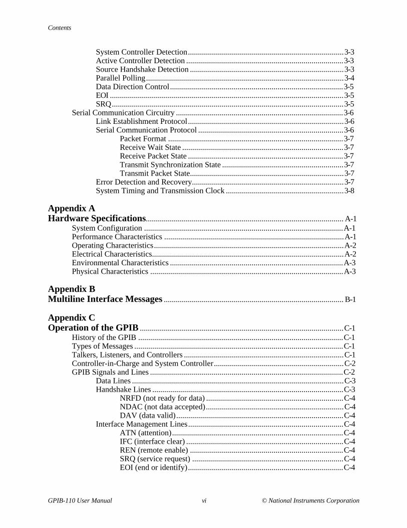
System Controller Detection..............................................................................3-3Active Controller Detection ...............................................................................3-3Source Handshake Detection .............................................................................3-3Parallel Polling...................................................................................................3-4Data Direction Control.......................................................................................3-5EOI .....................................................................................................................3-5SRQ....................................................................................................................3-5
Serial Communication Circuitry ....................................................................................3-6Link Establishment Protocol..............................................................................3-6Serial Communication Protocol .........................................................................3-6
Packet Format ........................................................................................3-7Receive Wait State .................................................................................3-7Receive Packet State ..............................................................................3-7Transmit Synchronization State .............................................................3-7Transmit Packet State.............................................................................3-7
Error Detection and Recovery............................................................................3-7System Timing and Transmission Clock ...........................................................3-8
Appendix AHardware Specifications................................................................................................... A-1
System Configuration ....................................................................................................A-1Performance Characteristics ..........................................................................................A-1Operating Characteristics...............................................................................................A-2Electrical Characteristics................................................................................................A-2Environmental Characteristics .......................................................................................A-3Physical Characteristics .................................................................................................A-3
Appendix BMultiline Interface Messages .......................................................................................... B-1
Appendix COperation of the GPIB ......................................................................................................C-1
History of the GPIB .......................................................................................................C-1Types of Messages .........................................................................................................C-1Talkers, Listeners, and Controllers ................................................................................C-1Controller-in-Charge and System Controller.................................................................C-2GPIB Signals and Lines .................................................................................................C-2
Data Lines ..........................................................................................................C-3Handshake Lines ................................................................................................C-3
NRFD (not ready for data) .....................................................................C-4NDAC (not data accepted).....................................................................C-4DAV (data valid)....................................................................................C-4
Interface Management Lines..............................................................................C-4ATN (attention)......................................................................................C-4IFC (interface clear) ...............................................................................C-4REN (remote enable) .............................................................................C-4SRQ (service request) ............................................................................C-4EOI (end or identify)..............................................................................C-4

Contents
GPIB-110 User Manual vii © National Instruments Corporation
Physical and Electrical Characteristics ..........................................................................C-5Configuration Restrictions: The Role of Extenders and Expanders .............................C-7
Appendix DCustomer Communication...............................................................................................D-1
Glossary ......................................................................................................................Glossary-1
Index .................................................................................................................................. Index-1
Figures
Figure 1-1. The Model GPIB-110 Bus Extender.................................................................1-1Figure 1-2. Typical GPIB-110 Extension System (Physical Configuration) ......................1-2Figure 1-3. Typical GPIB-110 Extension System (Logical Configuration)........................1-2
Figure 2-1. Isolation Selection ............................................................................................2-2Figure 2-2. Rear Panel.........................................................................................................2-4Figure 2-3. Configuration Switch........................................................................................2-5Figure 2-4. GPIB-110 Label................................................................................................2-5Figure 2-5. Internal Cable Selection Jumper (Shown for Coaxial Cable)...........................2-6
Figure 3-1. GPIB-110 Block Diagram ................................................................................3-2
Figure C-1. GPIB Cable Connector .....................................................................................C-3Figure C-2. Linear Configuration of the GPIB Devices ......................................................C-5Figure C-3. Star Configuration of GPIB Devices ................................................................C-6
Tables
Table 2-1. Transmit Clock Values Versus Cable Length ..................................................2-8
Table A-1. Performance Versus Distance...........................................................................A-1
Table A-2. Electrical Specifications ................................................................................... A-3

© National Instruments Corporation ix GPIB-110 User Manual
About This Manual
The GPIB-110 User Manual describes how to install, configure, and operate the GPIB-110. TheGPIB-110 is a high-performance bus extender that converts IEEE 488 signals into data packetsfor transmission to a matching GPIB-110, using a serial communication link to the distantextender. The receiving extender converts the packets back to IEEE 488 signals.
Organization of This Manual
This manual is organized as follows:
• Chapter 1, Description of the GPIB-110 , contains general information about the NationalInstruments GPIB-110, lists the contents of the GPIB-110 kit, and explains how to unpackthe GPIB-110 kit.
• Chapter 2, Configuration and Installation, contains instructions for configuring, installing,and verifying the operation of the GPIB-110.
• Chapter 3, Theory of Operation , contains an overview of the GPIB-110 and explains theoperation of each part of the GPIB-110.
• Appendix A, Hardware Specifications, lists the specifications of the GPIB-110.
• Appendix B, Multiline Interface Messages , lists the multiline interface messages anddescribes the mnemonics and messages that correspond to the interface functions. Thesefunctions include initializing the bus, addressing and unaddressing devices, and settingdevice modes for local or remote programming. The multiline interface messages areIEEE 488-defined commands that are sent and received with ATN TRUE.
• Appendix C, Operation of the GPIB , describes some basic concepts you should understand tooperate the GPIB. It also contains a description of the physical and electrical characteristicsas well as configuration requirements of the GPIB.
• Appendix D, Customer Communication, contains forms you can use to request help fromNational Instruments or to comment on our products and manuals.
• The Glossary contains an alphabetical list and description of terms used in this manual,including abbreviations, acronyms, metric prefixes, mnemonics, and symbols.
• The Index contains an alphabetical list of key terms and topics in this manual, including thepage where you can find each one.
About This Manual
GPIB-110 User Manual x © National Instruments Corporation
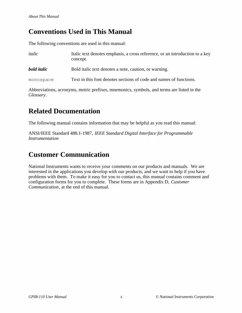
Conventions Used in This Manual
The following conventions are used in this manual:
italic Italic text denotes emphasis, a cross reference, or an introduction to a keyconcept.
bold italic Bold italic text denotes a note, caution, or warning.
monospace Text in this font denotes sections of code and names of functions.
Abbreviations, acronyms, metric prefixes, mnemonics, symbols, and terms are listed in theGlossary.
Related Documentation
The following manual contains information that may be helpful as you read this manual:
ANSI/IEEE Standard 488.1-1987, IEEE Standard Digital Interface for ProgrammableInstrumentation
Customer Communication
National Instruments wants to receive your comments on our products and manuals. We areinterested in the applications you develop with our products, and we want to help if you haveproblems with them. To make it easy for you to contact us, this manual contains comment andconfiguration forms for you to complete. These forms are in Appendix D, CustomerCommunication , at the end of this manual.

© National Instruments Corporation 1-1 GPIB-110 User Manual
Chapter 1Description of the GPIB-110
This chapter contains general information about the National Instruments GPIB-110, lists thecontents of the GPIB-110 kit, and explains how to unpack the GPIB-110 kit.
The GPIB-110 is a high-performance bus extender with the following features:
• Transparent to user software
• Extends the distance between GPIB instruments up to 2 km
• Transfer rates up to 144 kbytes/s
• Choice of fiber optic or coaxial cable
• Passes control over the GPIB
• FCC Class A (verified) noise emission
• Optional rack-mount hardware
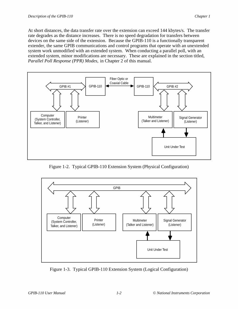
The high-speed GPIB-110 Bus Extender, shown in Figure 1-1, is used in pairs with serial fiberoptic or coaxial cables to connect two separate GPIB or IEEE 488 bus systems in a functionallytransparent manner. While the two bus systems are physically separate, as shown in Figure 1-2,devices operate as if located on the same bus, as shown in Figure 1-3.
Figure 1-1. The Model GPIB-110 Bus Extender
Description of the GPIB-110 Chapter 1
GPIB-110 User Manual 1-2 © National Instruments Corporation
At short distances, the data transfer rate over the extension can exceed 144 kbytes/s. The transferrate degrades as the distance increases. There is no speed degradation for transfers betweendevices on the same side of the extension. Because the GPIB-110 is a functionally transparentextender, the same GPIB communications and control programs that operate with an unextendedsystem work unmodified with an extended system. When conducting a parallel poll, with anextended system, minor modifications are necessary. These are explained in the section titled,Parallel Poll Response (PPR) Modes, in Chapter 2 of this manual.
GPIB #2GPIB-110
Fiber Optic or Coaxial Cable
GPIB #1 GPIB-110
Computer (System Controller, Talker, and Listener)
Printer (Listener)
Multimeter (Talker and Listener)
Signal Generator (Listener)
Unit Under Test
Figure 1-2. Typical GPIB-110 Extension System (Physical Configuration)
Computer (System Controller, Talker, and Listener)
Printer (Listener)
Multimeter (Talker and Listener)
Signal Generator (Listener)
Unit Under Test
GPIB
Figure 1-3. Typical GPIB-110 Extension System (Logical Configuration)

Chapter 1 Description of the GPIB-110
© National Instruments Corporation 1-3 GPIB-110 User Manual
With the GPIB-110, you can overcome the two following configuration restrictions imposed byANSI/IEEE Standard 488-1987:
• Cable length limit of 20 m per contiguous bus or 2 m times the number of devices on the bus,whichever is smaller.
• Electrical loading limit of 15 devices per contiguous bus.
Each GPIB-110 system extends the distance limit by 2 km and the loading limit to 30 devicesincluding the extenders. You can connect these point-to-point extender systems in series forlonger distances or in star patterns for additional loading.
What Your Kit Should Contain
Your GPIB-110 kit should contain the following components:
Kit Component Part Number
Model GPIB-110 Bus Extender
100-120 VAC:
Fiber Optic Version 776103-01
Coaxial Version 776103-02
Dual Fiber Optic and Coaxial Capability 776103-03
220-240 VAC:
Fiber Optic Version 776103-31
Coaxial Version 776103-32
Dual Fiber Optic & Coaxial Capability 776103-33
Power Cord:
U.S. standard 3-wire power cable 763000-01
GPIB-110 User Manual 320052-01
Description of the GPIB-110 Chapter 1
GPIB-110 User Manual 1-4 © National Instruments Corporation
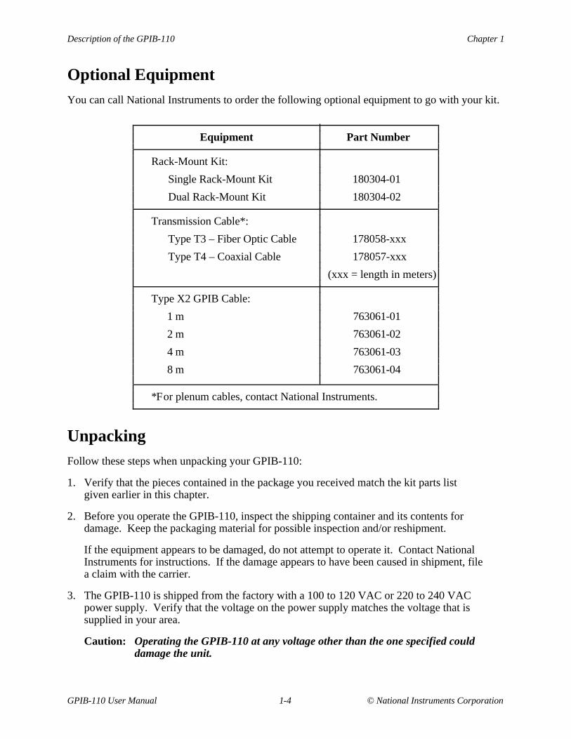
Optional EquipmentYou can call National Instruments to order the following optional equipment to go with your kit.
Equipment Part Number
Rack-Mount Kit:
Single Rack-Mount Kit 180304-01
Dual Rack-Mount Kit 180304-02
Transmission Cable*:
Type T3 – Fiber Optic Cable 178058-xxx
Type T4 – Coaxial Cable 178057-xxx
(xxx = length in meters)
Type X2 GPIB Cable:
1 m 763061-01
2 m 763061-02
4 m 763061-03
8 m 763061-04
*For plenum cables, contact National Instruments.
UnpackingFollow these steps when unpacking your GPIB-110:
1. Verify that the pieces contained in the package you received match the kit parts listgiven earlier in this chapter.
2. Before you operate the GPIB-110, inspect the shipping container and its contents fordamage. Keep the packaging material for possible inspection and/or reshipment.
If the equipment appears to be damaged, do not attempt to operate it. Contact NationalInstruments for instructions. If the damage appears to have been caused in shipment, filea claim with the carrier.
3. The GPIB-110 is shipped from the factory with a 100 to 120 VAC or 220 to 240 VACpower supply. Verify that the voltage on the power supply matches the voltage that issupplied in your area.
Caution: Operating the GPIB-110 at any voltage other than the one specified coulddamage the unit.

© National Instruments Corporation 2-1 GPIB-110 User Manual
Chapter 2Configuration and Installation
This chapter contains instructions for configuring, installing, and verifying the operation of theGPIB-110.
Users unfamiliar with the GPIB should first read Appendix C, Operation of the GPIB , to becomefamiliar with GPIB terminology and protocol before continuing with this chapter.
The GPIB-110 comes in the following three models:
• The 776103-01 (776103-31) model–Uses an optical fiber cable.
• The 776103-02 (776103-32) model–Uses a coaxial cable.
• The 776103-03 (776103-33) model–Uses either type of cable.
The GPIB-110 has several configurations depending on the type and length of cable used andother operating conditions.
Grounding Configuration
A U.S. standard 3-wire power cable is provided with the GPIB-110. When connected to a powersource, this cable connects the equipment chassis to the power ground.
The GPIB-110 is shipped from the factory with the logic ground of the digital circuitryconnected to both the power and chassis ground and interfacing cable shields.
If it is necessary to isolate either of these grounds to prevent current loops between units,disassemble the unit according to the following instructions.
Hazardous voltage inside. Remove power cord before opening unit.Warning:!
1. Turn the power switch to OFF. This switch is located on the rear panel of the GPIB-110.
2. Disconnect the power cord from the power source and from the rear panel of the GPIB-110.
3. Remove the cover from the GPIB-110 by first removing the two screws located on each sideof the housing. Lift off the cover.
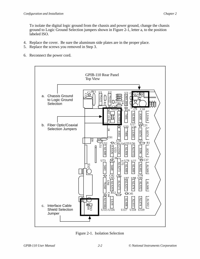
To isolate the interface cable shield from the chassis, power ground, and logic ground,change the interface cable Shield Selection Jumper shown in Figure 2-1, letter c, to theposition labeled ISO.
Configuration and Installation Chapter 2
GPIB-110 User Manual 2-2 © National Instruments Corporation
To isolate the digital logic ground from the chassis and power ground, change the chassisground to Logic Ground Selection jumpers shown in Figure 2-1, letter a, to the positionlabeled ISO.
4. Replace the cover. Be sure the aluminum side plates are in the proper place.5. Replace the screws you removed in Step 3.
6. Reconnect the power cord.
R3R4R5
CX
FOC2 RV1 U1 U2 U3 C5
J2
C1
R2
R1 C60C9
R6
C3 U4
U15 U16
C6
C7
C10
C8
U20
J4M
IT J3 R
CV
C61R9
D9
U51
U52
U17 U18
D1
D2
D3
C21
U34
U35 U36
U37C30
U53
U54U55 U56
U57
R1
U73 U74
U75
U76 U77
U78
S1J5
C42
U94
U95U96
U97 U98 U99
C44
C36C37
C45R12
U116 U117 U118 U119
ISOSH
U115
75121
75122
AL
S00
7406
AL
S04
AS00
LS164
AS02
7406
LS393
26012601
AS74
AS74
AL
S00
LS126
LS164
AL
S04
AL
S151
S196
AS74
3441
3448
AL
S273
AL
S00
AL
S00
AL
S02
AL
S00
76160
AL
S257
AL
S273
AL
S257
AL
S74
AL
S32
AL
S08
LS19
AL
S08
AL
S11
AL
S74
AL
S02
AL
S166
Fiber Optic/Coaxial Selection Jumpers
Chassis Ground to Logic Ground Selection
a.
GPIB-110 Rear Panel Top View
b.
Interface Cable Shield Selection Jumper
c.
ISO
Figure 2-1. Isolation Selection

Chapter 2 Configuration and Installation
© National Instruments Corporation 2-3 GPIB-110 User Manual
The GPIB-110 Front and Rear Panels
In the following discussions, the terms local and remote refer to certain states of the twoGPIB-110 Bus Extenders. When one extender is in a local state, meaning that the state inquestion originated on its side, the other extender is in the corresponding remote state. The threestates in question are the System Controller, Active Controller, and Source Handshake.
The GPIB-110 Front Panel
The GPIB-110 front panel is shown in Chapter 1, Figure 1-1. The front panel has nine LightEmitting Diodes (LEDs). The PWR LED on the left side of the front panel lights up wheneverpower is applied to the GPIB-110.
The Serial Communication LEDs are LINK and ERR (error). The GPIB-110 condenses the 16IEEE 488 signals into data packets that are sent across the serial link and are converted back toIEEE 488 signals by the remote GPIB-110. When lit, the LINK LED indicates that the remoteGPIB-110 is on and the extension is operating normally. The ERR LED flashes whenever a datapacket containing an error is received.
The System Controller, Active Controller, and Source Handshake each have two LEDsindicating local (LOC) and remote (REM). If the System Controller LOC LED is lit, theInterface Clear (IFC) or Remote Enable (REN) message has been detected on the local GPIB. Ifthe System Controller REM LED is lit, IFC or REN has been received from the remote unit. Ifthe Active Controller LOC LED is lit, the Attention (ATN) message has been detected on thelocal GPIB. If the Active Controller REM LED is lit, ATN has been received from the remoteunit. If the Source Handshake LOC LED is lit, a Data Valid (DAV) message has been detectedon the local GPIB; that is, the Talker is on the local GPIB. If the REM LED lights up, DAV hasbeen received from the remote unit; that is, the Talker is on the remote side.
Configuration and Installation Chapter 2
GPIB-110 User Manual 2-4 © National Instruments Corporation
The GPIB-110 Rear Panel
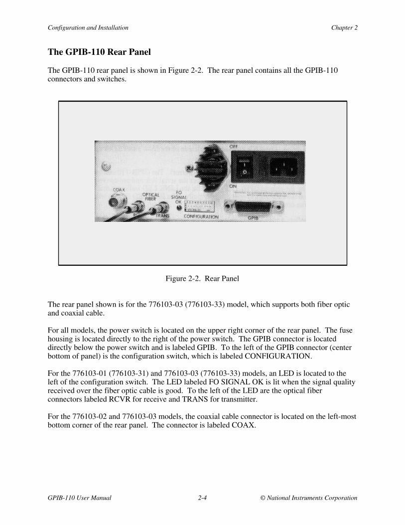
The GPIB-110 rear panel is shown in Figure 2-2. The rear panel contains all the GPIB-110connectors and switches.
Figure 2-2. Rear Panel
The rear panel shown is for the 776103-03 (776103-33) model, which supports both fiber opticand coaxial cable.
For all models, the power switch is located on the upper right corner of the rear panel. The fusehousing is located directly to the right of the power switch. The GPIB connector is locateddirectly below the power switch and is labeled GPIB. To the left of the GPIB connector (centerbottom of panel) is the configuration switch, which is labeled CONFIGURATION.
For the 776103-01 (776103-31) and 776103-03 (776103-33) models, an LED is located to theleft of the configuration switch. The LED labeled FO SIGNAL OK is lit when the signal qualityreceived over the fiber optic cable is good. To the left of the LED are the optical fiberconnectors labeled RCVR for receive and TRANS for transmitter.
For the 776103-02 and 776103-03 models, the coaxial cable connector is located on the left-mostbottom corner of the rear panel. The connector is labeled COAX.
Chapter 2 Configuration and Installation
© National Instruments Corporation 2-5 GPIB-110 User Manual
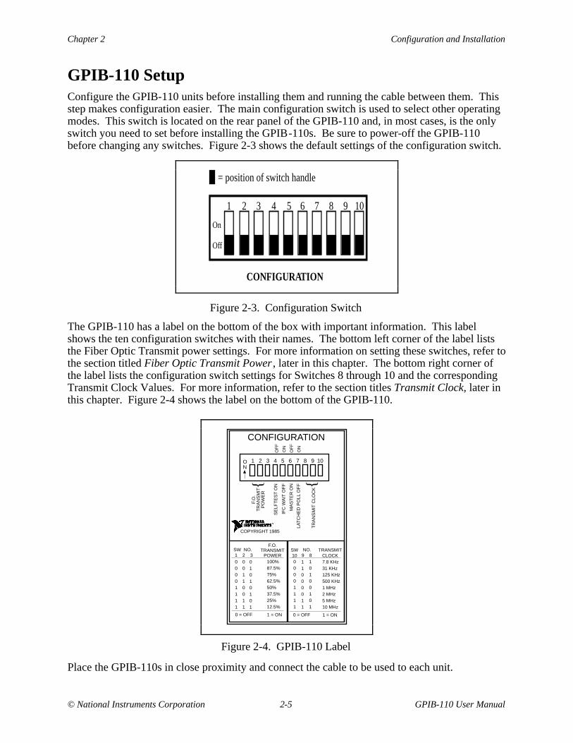
GPIB-110 SetupConfigure the GPIB-110 units before installing them and running the cable between them. Thisstep makes configuration easier. The main configuration switch is used to select other operatingmodes. This switch is located on the rear panel of the GPIB-110 and, in most cases, is the onlyswitch you need to set before installing the GPIB-110s. Be sure to power-off the GPIB-110before changing any switches. Figure 2-3 shows the default settings of the configuration switch.
On
Off
31 2 4 5 6 7 8 9 10
CONFIGURATION
= position of switch handle
Figure 2-3. Configuration Switch
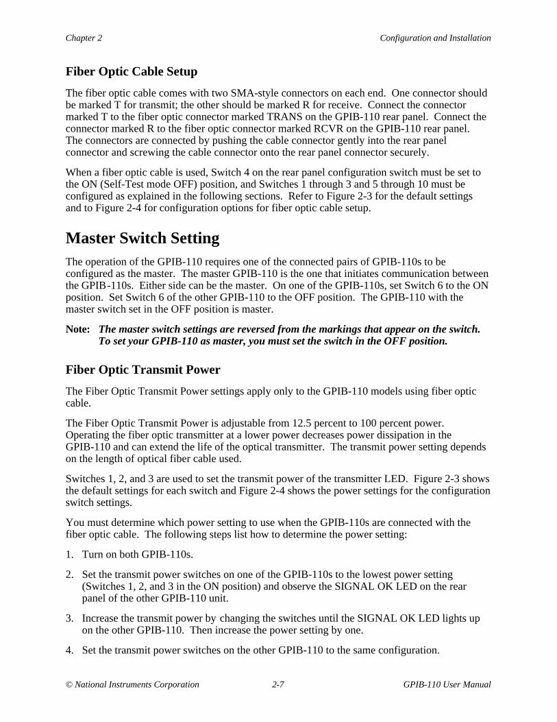
The GPIB-110 has a label on the bottom of the box with important information. This labelshows the ten configuration switches with their names. The bottom left corner of the label liststhe Fiber Optic Transmit power settings. For more information on setting these switches, refer tothe section titled Fiber Optic Transmit Power , later in this chapter. The bottom right corner ofthe label lists the configuration switch settings for Switches 8 through 10 and the correspondingTransmit Clock Values. For more information, refer to the section titles Transmit Clock, later inthis chapter. Figure 2-4 shows the label on the bottom of the GPIB-110.
CONFIGURATION
1 2 3 4 5 6 7 8 9 10ON
COPYRIGHT 1985
F.O
.T
RA
NS
MIT
PO
WE
R
SE
LFT
ES
T O
N
IFC
WA
IT O
FF
MA
ST
ER
ON
LAT
CH
ED
PO
LL O
FF
TR
AN
SM
IT C
LOC
K
OF
F
OF
F
ON
ON
SW10
NO. 9 8
TRANSMITCLOCK
00001111
11000011
10100101
7.8 KHz31 KHz125 KHz500 KHz1 MHz2 MHz5 MHz10 MHz
0 = OFF 1 = ON
SW 1
NO.2 3
F.O.TRANSMIT
POWER00001111
00110011
01010101
100%87.5%75%62.5%50%37.5%25%12.5%
0 = OFF 1 = ON
Figure 2-4. GPIB-110 Label
Place the GPIB-110s in close proximity and connect the cable to be used to each unit.

Configuration and Installation Chapter 2
GPIB-110 User Manual 2-6 © National Instruments Corporation
Cable Selection
The GPIB-110 is shipped with either a coaxial or fiber optic cable and with the cable selectionjumper set according to the model number. However, if you have to change the type of cableyou are using, you must also change the jumper setting located on the inside of the GPIB-110 asshown in Figure 2-5. (See Figure 2-1, letter b, for the location of this jumper.)
CX
FO
RCV XMIT
Figure 2-5. Internal Cable Selection Jumper (Shown for Coaxial Cable)
Use the following steps to change the setting of the cable selection jumper.
Hazardous voltage inside. Remove power cord before opening unit.Warning:!
1. Turn the power switch to OFF. This switch is located on the rear panel of the GPIB-110.
2. Disconnect the power cord from the power source and from the rear panel of the GPIB-110.
3. Remove the cover from the GPIB-110 by first removing the two screws located on each sideof the housing. Lift off the cover.
4. The Internal Cable Selection Jumper, shown in Figure 2-5, is located underneath thetransformer near the rear panel. (See Figure 2-1, letter b, for the exact location.) Usingneedle-nosed pliers (right angle works best), place the two blue jumpers on the correctsetting. The position labeled FO is for fiber optic cable. The position labeled CX is forcoaxial cable.
5. Replace the cover. Be sure the aluminum side plates are in the proper place.
6. Replace the screws you removed in Step 3.
7. Reconnect the power cord.
Coaxial Cable Setup
The coaxial cable should be connected to the Coaxial BNC connector on the rear panel of theGPIB-110. When using a coaxial cable, Switch 4 on the rear panel configuration switch must beset to ON (Self-Test mode OFF), and Switches 5 through 10 must be configured as explained inthe following sections. Refer to Figure 2-3 for the default settings of the configuration switchand Figure 2-4 for other possible configurations.
Chapter 2 Configuration and Installation
© National Instruments Corporation 2-7 GPIB-110 User Manual
Fiber Optic Cable Setup
The fiber optic cable comes with two SMA-style connectors on each end. One connector shouldbe marked T for transmit; the other should be marked R for receive. Connect the connectormarked T to the fiber optic connector marked TRANS on the GPIB-110 rear panel. Connect theconnector marked R to the fiber optic connector marked RCVR on the GPIB-110 rear panel.The connectors are connected by pushing the cable connector gently into the rear panelconnector and screwing the cable connector onto the rear panel connector securely.
When a fiber optic cable is used, Switch 4 on the rear panel configuration switch must be set tothe ON (Self-Test mode OFF) position, and Switches 1 through 3 and 5 through 10 must beconfigured as explained in the following sections. Refer to Figure 2-3 for the default settingsand to Figure 2-4 for configuration options for fiber optic cable setup.
Master Switch SettingThe operation of the GPIB-110 requires one of the connected pairs of GPIB-110s to beconfigured as the master. The master GPIB-110 is the one that initiates communication betweenthe GPIB-110s. Either side can be the master. On one of the GPIB-110s, set Switch 6 to the ONposition. Set Switch 6 of the other GPIB-110 to the OFF position. The GPIB-110 with themaster switch set in the OFF position is master.
Note: The master switch settings are reversed from the markings that appear on the switch.To set your GPIB-110 as master, you must set the switch in the OFF position.
Fiber Optic Transmit Power
The Fiber Optic Transmit Power settings apply only to the GPIB-110 models using fiber opticcable.
The Fiber Optic Transmit Power is adjustable from 12.5 percent to 100 percent power.Operating the fiber optic transmitter at a lower power decreases power dissipation in theGPIB-110 and can extend the life of the optical transmitter. The transmit power setting dependson the length of optical fiber cable used.
Switches 1, 2, and 3 are used to set the transmit power of the transmitter LED. Figure 2-3 showsthe default settings for each switch and Figure 2-4 shows the power settings for the configurationswitch settings.
You must determine which power setting to use when the GPIB-110s are connected with thefiber optic cable. The following steps list how to determine the power setting:
1. Turn on both GPIB-110s.
2. Set the transmit power switches on one of the GPIB-110s to the lowest power setting(Switches 1, 2, and 3 in the ON position) and observe the SIGNAL OK LED on the rearpanel of the other GPIB-110 unit.
3. Increase the transmit power by changing the switches until the SIGNAL OK LED lights upon the other GPIB-110. Then increase the power setting by one.
4. Set the transmit power switches on the other GPIB-110 to the same configuration.

Configuration and Installation Chapter 2
GPIB-110 User Manual 2-8 © National Instruments Corporation
Transmit Clock
The GPIB-110 has a variable transmit frequency that must be set for a given length of fiber opticor coaxial cable. If you are using fiber optic cable, set the transmit clock to 10 MHz for anylength of cable. For a coaxial cable, you must reduce the transmit clock values as the cablelength increases. Set Switches 8, 9, and 10 on the rear panel configuration switch so the transmitclock value corresponds to your cable length. Table 2-1 shows the appropriate transmit clockvalues versus cable length.
Table 2-1. Transmit Clock Values Versus Cable Length
Cable Type Cable Length Transmit Clock ConfigurationSwitch Setting
10 9 8
Coaxial 0 m to 240 m 10 MHz 1 1 1Cable 240 m to 425 m 5 MHz 1 1 0
425 m to 730 m 2 MHz 1 0 1730 m to 1035 m 1 MHz 1 0 0
1035 m to 1340 m 500 KHz 0 0 01340 m to 1765 m 125 KHz 0 0 11765 m to 2000 m 31 KHz 0 1 0
Note: 0 = Off1 = ON
Fiber Optic Any Length 10 MHz 1 1 1Cable
Extension Modes
The GPIB-110 has two extension modes–Immediate Extension mode and IFC Wait mode. BothGPIB-110 units in the extension system must be set to the same mode using Switch 5, which islocated on the rear panel configuration switch.
Immediate Extension Mode
The GPIB-110 is set at the factory to the Immediate Extension mode (Switch 5 OFF). In thismode, the extenders connect the two local GPIB buses as soon as they are both turned on.

Chapter 2 Configuration and Installation
© National Instruments Corporation 2-9 GPIB-110 User Manual
IFC Wait Mode
In IFC Wait Mode (Switch 5 ON), the GPIB-110s do not connect the two local GPIB buses untilan IFC signal is detected. This mode requires a System Controller on one side of the extensionand any number of Talkers, Listeners, and other Controllers in the system. This mode causes theGPIB-110s to be synchronized with the local buses so that the buses do not disturb each otherwhen the GPIB-110s are turned on.
In IFC Wait mode, the two GPIB-110s wait to detect the following information in this sequence:
1. The Interface Clear (IFC) signal from the System Controller
2. The Attention (ATN) signal from the Active Controller
3. The Data Valid (DAV) signal from the Active Controller or Talker
Both units turn on in a quiescent condition without an active local or remote state. They remainthis way until one unit detects an IFC true from the System Controller that is on the samecontiguous bus. That unit enters the Local System Controller (LSC) state and causes the otherunit to enter the Remote System Controller (RSC) state. The IFC and Remote Enable (REN)signals are switched to flow from the local to the remote unit. Next, one unit detects theAttention (ATN) signal from the Active Controller, enters the Local Active Controller (LAC)state, and places the other unit in the Remote Active Controller (RAC) state. The ATN signal isswitched to flow from the local to the remote side and the Service Request (SRQ) is switched toflow in the opposite direction. Finally, one unit detects the Data Valid (DAV) signal from theSource Handshake function of the Talker or Active Controller. That unit enters the Local Source(LS) state and places the other unit in the Remote Source (RS) state. The DAV and Data (DIO)signals are switched to flow from local to remote side, and the Not Ready for Data (NRFD) andNot Data Accepted (NDAC) signals are switched to flow from remote to local side.
As the source side for these three key signals (IFC, ATN, and DAV) change, the local/remotestates of each extender change. The directions of the other GPIB signals change accordingly.See the Active Controller Detection and Source Handshake Detection sections in Chapter 3 formore information about this operation.
Parallel Poll Response (PPR) ModesAccording to the ANSI/IEEE Standard 488-1987, devices must respond to a parallel poll within200 ns after the Identify (IDY) message is asserted by the Active Controller, which then waits 2µs or more to read the Parallel Poll Response (PPR). A remote device on an extended systemcannot respond this quickly because of cable propagation delay. GPIB extender manufacturershave approached this problem in three ways:
Approach 1: Respond to IDY within 200 ns with the results of the previous poll of the remotebus.
Approach 2: Ignore the 200 ns rule and assume the Controller will wait sufficiently long tocapture the response.
Approach 3: Do not support parallel polling at all.

Configuration and Installation Chapter 2
GPIB-110 User Manual 2-10 © National Instruments Corporation
The GPIB-110 supports either Approach 1 or 2 selected by Switch 7, which is located on the rearpanel configuration switch as shown in Figure 2-3.
Latched PPR Mode (Approach 1)
This mode is selected by setting Switch 7 ON. Most Controllers pulse the IDY signal for aperiod of time exceeding 2 µs and expect a response within that time. When used with this typeof Controller, the GPIB-110 must be set in the Latched PPR mode. After power on, the initialpoll response is FFH, subsequent poll responses are the results of the previous poll.
In this mode, the local GPIB-110 extender responds to IDY by outputting the contents of thePPR data register. At the same time, a parallel poll message is sent to the remote bus and thepoll response is returned to the local unit. When the local IDY signal is unasserted, the registeris loaded with the new remote response. Consequently, the register contains the response of theprevious poll. To obtain the response of both the local and remote buses, the control programexecutes two parallel polls back-to-back and uses the second response.
The software driver library of most Controllers contains an easy-to-use parallel poll function.For example, if the function is called PPOLL and the control program is written in BASIC, thesequence to conduct a poll in Latched PPR mode might be like this:
CALL PPOLL(PPR)CALL PPOLL(PPR)IF PPR > 0 GOTO NNN
If two GPIB extender systems are connected in series, three polls are necessary to get responsesfrom the local, middle, and far buses.
Unlatched PPR Mode (Approach 2)
Many Hewlett-Packard GPIB Controllers remain in a parallel poll state with IDY assertedwhenever they are not performing another function. A change in the response causes an interruptof the control program. In other Controllers, the IDY signal is toggled on and off and theduration of the signal can vary to accommodate delayed responses over extenders.
When used with these types of Controllers, the GPIB-110 should be set to Unlatched PPR modeby setting Switch 7 to the OFF position. This means that the IDY message is sent to the remotebus and the response is returned as fast as propagation delays allow. It is the responsibility of theController to wait long enough for the response.
Mixed Mode Option
If there are multiple Controllers and all of the same type are located on the same side of theextension, the two GPIB-110 units can be set to Latched and Unlatched PPR modes accordingly.

Chapter 2 Configuration and Installation
© National Instruments Corporation 2-11 GPIB-110 User Manual
InstallationAfter configuring both GPIB-110s and connecting the coaxial or fiber optic cable, follow theseinstructions:
Verify the Voltage Requirement
The GPIB-110 is shipped from the factory with either a 100 to 120 VAC or 220 to 240 VACinternal power supply. Verify that the voltage specified on the power supply matches the voltagesupplied in your area.
Caution: Operating the unit at any voltage other than the one specified could damagethe unit.
1. Plug the utility power cord into an acceptable electrical outlet (100 to 120 VAC or 220 to 240VAC, depending upon which model of the GPIB-110 you have). Then plug the other end ofthe power cord into the back panel of the GPIB.
2. Link the first GPIB to the GPIB-110 with an appropriate cable (Type X1 or better). Thecable coming from the GPIB should be plugged into the back panel of the GPIB-110.
3. Link the second GPIB to the remote GPIB-110 with the appropriate GPIB cable.
MountingThe GPIB-110 enclosure is designed for table top or rack-mount operation. Single- and dual-unit rack-mount kits are available from National Instruments.
Power OnThe GPIB-110 extension system is fully operational when power is applied to both units andthey are connected. If the extenders are set for IFC Wait Mode, it may be necessary to turn onthe System Controller last after the extenders and all other devices are operating. This step isnecessary if the System Controller executes only one IFC shortly after power on.
The preferred operating mode is to keep both extenders and at least two-thirds of the devices onboth buses turned on when there is any GPIB activity.
Self-Test ModeThe GPIB-110s are equipped with a Self-Test mode that determines if the GPIB-110 receivers,transmitters, and packet transmission and reception circuitry are operating correctly. This modeis controlled by Switch 4.
This mode should be used only if you want to check the operation of the GPIB-110. It is notnecessary to use this mode to operate the GPIB-110s.
Note: The self-test switch settings are reversed from the markings that appear on the switch.To set your GPIB-110 for self-test mode, you must set the switch in the OFF position.
Configuration and Installation Chapter 2
GPIB-110 User Manual 2-12 © National Instruments Corporation
Self-Test with Coaxial Cable
Use the following steps to run the Self-Test mode with the coaxial cable.
1. Turn the GPIB-110 power switch to OFF.
2. Disconnect the coaxial cable from the rear panel connector.
3. Set the master switch to the ON position (Switch 6 OFF) and the self-test switch to the ONposition (Switch 4 OFF).
4. Turn the GPIB-110 power switch to ON.
At this point, the LINK LED on the front panel lights up indicating that the Self-Test mode isoperating correctly. In addition, the ERR LED remains off.
Note: Be sure to turn the self-test switch to the OFF position (Switch 4 ON) and the masterswitch to the original position and reconnect the coaxial cable before re-using theGPIB-110.
Self-Test with Fiber Optic Cable
To run the Self-Test mode with the fiber optic cable, you must connect a single fiber optic cablein a loop from the transmit output to the receive input of the GPIB-110. You can use theopposite ends of the extension cable, or purchase a short loopback cable from NationalInstruments.
Use the following steps to run the Self-Test mode with the fiber optic cable.
1. Turn the GPIB-110 power switch to OFF.
2. Disconnect the fiber optic cable from the rear panel transmit and receiver connectors.
3. Connect the transmitter connector to the receiver connector with a single fiber optic cable.
4. Set the master switch to the ON position (Switch 6 OFF) and the self-test switch to the ONposition (Switch 4 OFF).
5. Turn the GPIB-110 power switch to ON.
At this point, the LINK LED on the front panel lights up indicating that the Self-Test mode isoperating correctly. The ERR LED should remain off.
Note: Be sure to turn the self-test switch to the OFF position (Switch 4 ON) and the masterswitch to the original position and reconnect the fiber optic extension cable beforere-using the GPIB-110.

Chapter 2 Configuration and Installation
© National Instruments Corporation 2-13 GPIB-110 User Manual
Connecting to Hewlett-Packard (HP) Controllers
To achieve high data transfer rates and long cable spans between devices, many HP controllersand computers, such as the 64000 series, use a preload technique on the unit designated MasterController. When preloaded, the GPIB lines of the Master Controller are terminated to representsix device loads. HP has two types of preloading: Class A, in which all 16 GPIB lines areloaded, and Class B, in which all except Not Ready For Data (NRFD) and Not Data Accepted(NDAC) messages are loaded.
Preloading increases ringing on signal transitions and can cause improper operation of theGPIB-110. If this happens, set all signals on the Master Controller to normal (1-unit) load. Thisis done by using a back-panel switch. It is also important to limit the cabling to no more than 2mper device.

© National Instruments Corporation 3-1 GPIB-110 User Manual
Chapter 3Theory of Operation
This chapter contains an overview of the GPIB-110 and explains the operation of each part of theGPIB-110.
The GPIB-110 design consists of two main parts:
• The extension circuitry
• The serial communication circuitry
The extension circuitry monitors the local GPIB states and converts the signals monitored intothe X (for transmit) signals that are sent to the serial communication circuitry.
The serial communication circuitry samples the X signal lines and serializes the information intopackets that are transmitted to the remote GPIB-110 unit.
The serial communication circuitry decodes packets received from the remote unit and convertsthe packets into the parallel GPIB signals prefixed with an R (for receive) that are sent to theextension circuitry.
The extension circuitry monitors the R signal lines and drives the local GPIB lines accordingly.

Theory of Operation Chapter 3
GPIB-110 User Manual 3-2 © National Instruments Corporation
Figure 3-1 shows a block diagram of the GPIB-110.
System ControllerDetection
Power On Delay
Active Controller Detection
Source Handshake Detection and
Handshake Control
Packet Transmission
TransmissionSynchronization
and TimingGP
IB S
tate
Sa
mp
ling
Pa
ralle
l To
Se
ria
l Co
nve
rsio
n
IFC Wait
Error Detectionand Recovery
Parallel PollControl
Data Direction Control
LatchedPPR
GP
IB T
ran
sce
ive
rs
Parallel PollResponseRegisterG
PIB
Tra
nsc
eiv
ers
Se
ria
l To
Pa
ralle
l Co
nve
rsio
n
Mu
ltip
lexe
r
GP
IB
Extension Circuitry
System Timing and Transmission Clock
Master
Transmit Data
TransmitClock
Selftest Mode
Sys
tem
Clo
ck
Fib
er
Op
tic
Tra
nsm
itte
r a
nd
Re
ceiv
er
Link Establishment
F.O. TransmitPower
Co
ax
Tra
nsm
itte
r a
nd
Re
ceiv
er
Receive Data
Communication Circuitry
Packet Reception
Packet Receptionand
Decoding Timing
Figure 3-1. GPIB-110 Block Diagram
Extension CircuitryThe extension circuitry converts signals received from the local GPIB to the X signals, as shownin Figure 3-1, and drives the R signals onto the local GPIB. The X signals sent from oneGPIB-110 unit after serialization and transmission, become the R signals on the remoteGPIB-110 unit after being received and converted back into parallel form. The SystemController, Active Controller, and Source Handshake states on the GPIB-110 unit determinewhich GPIB signals are sensed and/or driven.
Power On
When the GPIB-110 is turned on, a reset pulse clears all circuitry to an initialized state. Theunits then begin executing the link establishment protocol, which is discussed in the LinkEstablishment Protocol section later in this chapter.
Chapter 3 Theory of Operation
© National Instruments Corporation 3-3 GPIB-110 User Manual
After the GPIB-110 is turned on, the GPIB transceivers are in a passive, receive state (notdriving anything on the GPIB). The extender remains in this state until communication isestablished with the remote GPIB-110 unit.
Once the link is established, the GPIB-110 is able to monitor the local GPIB state and receivepackets containing the remote GPIB state.
System Controller Detection
The GPIB-110 monitors the location of the System Controller with the System Controllerdetection circuitry.
When IFC or REN true is received from the local GPIB, the Local System Controller (LSC) statebecomes true. The X.IFC or X.REN signal is then sent true to the communication circuitrywhere it is sent to the remote unit. The LSC state is cleared if R.IFC or R.REN is received truefrom the remote unit and IFC or REN is not true on the local GPIB.
R.IFC or R.REN true is received from the remote GPIB-110 unit, the Remote System Controller(RSC) state becomes true. The IFC and REN signals are then driven onto the local GPIB. TheRSC state is cleared if IFC or REN true is sensed from the local bus and R.IFC or R.REN is notreceived true.
Active Controller Detection
The GPIB-110 monitors the location of the Active Controller with the Active Controllerdetection circuitry. The location of the Active controller is determined by sensing the location ofATN. After power on, the Remote Active Controller (RAC) and Local Active Controller (LAC)states are cleared.
When ATN is received from the local bus, the LAC state becomes true on the leading edge ofATN. X.ATN is then sent to the remote unit. LAC true allows the local unit to receive SRQfrom the remote unit and to drive the SRQ line on the local bus. LAC is cleared if R.ATN isreceived from the remote unit and ATN is false on the local GPIB.
When R.ATN is received from the remote unit, the RAC state becomes true. When RAC is true,the local ATN signal is driven according to the state of R.ATN received from the remote side.The local state of SRQ is sent to the remote side (that is, to the Active Controller). RAC iscleared if ATN is true on the local GPIB and R.ATN is received false.
If IFC Wait mode is selected, both the RAC and LAC states remain cleared until either the LSCor the RSC state is true.
Source Handshake Detection
The GPIB-110 monitors the location of the Source Handshake. The location of the SourceHandshake is determined by the location of DAV.
The Local Source (LS) Handshake and Remote Source (RS) Handshake states are cleared uponpower on.

Theory of Operation Chapter 3
GPIB-110 User Manual 3-4 © National Instruments Corporation
The LS Handshake state is also cleared on the following events:
• When IFC Wait mode is selected with Switch 5 on the rear panel configuration switch andbefore the Active Controller is identified
• Whenever ATN from the local bus or R.ATN changes state
• When ATN or DAV is received from the remote unit
• During a parallel poll
The Remote Source (RS) Handshake state is cleared during the following events:
• When IFC Wait Mode is selected with Switch 5 on the rear panel configuration switch andbefore the Active Controller is identified
• Whenever there is a change in state from the remote ATN signal
• When ATN or DAV is received from the local GPIB
• During a parallel poll
Until the LS state is true and unless a parallel poll is in progress, the unit drives the local NRFDsignal passively false. After the Active Controller is identified (if in IFC Wait mode) and untilthe Source Handshake is identified, the unit drives NDAC true. Thus, the unit appears to thelocal GPIB to be in a normal RFD/NDAC state, awaiting the first data or command byte.
When DAV is received from the Local GPIB, the LS state becomes true. DAV is then sent tothe remote unit as X.DAV.
When R.DAV is received from the remote unit, the signal is delayed 2 µs and the RS statebecomes true. Once the RS state is true, DAV is driven onto the local GPIB. Subsequently,whenever R.DAV true is received from the remote unit, the signal is delayed 500 ns before beingdriven onto the local GPIB to satisfy T1. The local NRFD and NDAC are sensed and sent to theremote unit as X.RFD and X.DAC.
Once the LS state is true, the propagation of R.RFD from the remote side allows the handshaketo continue. At this point, the unit drives the NRFD and NDAC lines according to the levelssensed at the remote unit and received as R.RFD and R.DAC.
Parallel Polling
When the GPIB-110 detects ATN and EOI simultaneously asserted on the local bus, the ParallelPoll-In-Progress state becomes true and X.EOI is transmitted to the remote side along withX.ATN. X.EOI and X.ATN continue to be propagated to the remote side until a Parallel PollResponse is returned from the remote unit, even if the local ATN and EOI signals become false.NRFD is asserted on the local bus during the Parallel Poll.
If the latched Parallel Poll Response (PPR) mode is selected, the contents of the PPR register aredriven onto the local GPIB DIO lines. Otherwise, the local GPIB DIO lines are driven passivelyfalse until a packet is received from the remote unit containing the Parallel Poll Response. TheGPIB DIO lines are then driven with the response byte when it is received.

Chapter 3 Theory of Operation
© National Instruments Corporation 3-5 GPIB-110 User Manual
X.EOI and X.ATN are received on the remote side as R.EOI and R.ATN and propagated to theGPIB. Two microseconds later, the Parallel Poll Response on the remote side GPIB is sampledand returned as the Parallel Poll Response to the local unit. When the Parallel Poll Response isreceived by the local unit, the Parallel Poll Response byte is driven onto the GPIB DIO lines ifthe GPIB-110 is not in latched Parallel Poll mode.
When the Parallel Poll Response is received from the remote unit, and the local EOI signal goesfalse, the Parallel Poll-In-Progress state becomes false. This event causes the Parallel Pollregister to latch the Parallel Poll Response when operating in latched Parallel Poll mode. Theextender then stops driving NRFD true.
Data Direction Control
The unit drives the GPIB data lines DIO1-8 from R.DIO1-8 if there is a local Parallel Poll inprogress or if the RS state is true and a remote Parallel Poll is not in progress. Otherwise, theselines are not driven.
When a packet containing DAV true or RPP true is received and unlatched parallel poll responsemode is selected, the GPIB data lines are driven with the data from the data packet received fromthe remote unit. If DAV is not true during a Parallel Poll, the data lines are driven from theParallel Poll Response register.
The local unit sends the data lines to the remote unit via X.DIO1-8 if there is a remote ParallelPoll in progress or if the LS state is true and a local Parallel Poll is not in progress. Otherwise,the data bytes are not sent.
EOI
The local unit transmits EOI to the remote unit as X.EOI if the LS state is true. X.EOI isasserted from the start of a local Parallel Poll until the poll handshake signal is received from theremote unit and the local poll completes.
X.EOI is received as R.EOI at the remote unit. X.EOI propagates to the remote GPIB if the localunit is conducting a Parallel Poll or if the RS state is true and the local unit is not conducting aParallel Poll.
SRQ
The local GPIB unit transmits X.SRQ to the remote unit if the location of the Active Controllerhas not been detected. The remote unit drives the local bus according to the value of R.SRQreceived.
When the location of the Active Controller has been detected, SRQ is sent to the remote unitonly if the Active Controller is on the remote unit side.
Theory of Operation Chapter 3
GPIB-110 User Manual 3-6 © National Instruments Corporation
Serial Communication Circuitry
The GPIB-110 units connected via a serial link maintain their communication through the use ofdigital packets. The serial communication circuitry is responsible for converting packets fromparallel-to-serial form for transmission and back to parallel form after reception. The circuitryalso maintains continuous communication between the extenders and is responsible for packeterror-detection and recovery.
Link Establishment Protocol
The two GPIB-110s use a protocol in which each extender transmits a packet as soon as a packetis received. In this way, communication between the extenders is continuous. The LINK LEDon the GPIB-110 front panel lights up when the unit is receiving error-free packets from theremote unit.
When you power on, the master GPIB-110 transmits a packet to the remote unit and waitsapproximately 30 µs for a packet to be received. If a packet is not received, the GPIB-110 timesout and retransmits the packet. This process continues until a packet is received.
When you power on, the non-master GPIB-110 waits to receive a packet from the masterGPIB-110 unit.
The extender link is established when a GPIB-110 receives two successive packets withouterrors. When the packets are received, the LINK LED on the front panel lights up indicating thatthe remote unit is turned on and operating properly. The extension is then operational.
When the remote unit no longer receives packets, the extender times out, turns off the LINKLED, and stops driving the local GPIB.
Serial Communication Protocol
The extender Serial Communication Protocol consists of each extender transmitting a packetwhenever one is received while the link is established. In this way, each GPIB-110 unit canmonitor that the remote unit is still on.
Transmission and reception of packets consists of four states:
• Receive Wait state
• Receive Packet state
• Transmit Synchronization state
• Transmit Packet state
If a communication error occurs, the GPIB-110 attempts to recover from the error as explained inthe section, Error Detection and Recovery , later in this chapter.
Chapter 3 Theory of Operation
© National Instruments Corporation 3-7 GPIB-110 User Manual
Packet Format
Information is sent between GPIB-110 units via digital packets. The packet is made up of one ormore start bits, followed by encoded GPIB information, and terminated by a cyclical redundancycheck code. Each packet also contains a sequence number.
Receive Wait State
The Receive Wait state is entered after a packet has been transmitted to the remote unit. TheGPIB-110 has a timeout circuit that corresponds to twice the propagation delay of 2 km of cableplus a GPIB-110 transmit wait time and the time it takes to transmit one packet. This equalsapproximately 26 µs plus the time it takes to transmit one packet, which varies depending on thetransmit clock used. If a packet is not received within this time, the GPIB-110 goes into an errorstate.
Once a packet is received, the Receive Wait state is exited and the Receive Packet state isentered.
Receive Packet State
In the Receive Packet state, a packet is received and converted into parallel information as it isreceived. A redundancy check code is generated for the packet as it is received. This code iscompared with the cyclical redundancy check code appended to the packet. If an error isdetected, the packet is discarded. Otherwise, the packet information is latched and sent to theextension circuitry. The GPIB-110 then enters the Transmit Synchronization state.
Transmit Synchronization State
In the Transmit Synchronization state, the GPIB-110 waits up to approximately 3 µs for a changeto occur on the local GPIB. A change consists of a change in the state of the IFC, REN, ATN,DAV, or RFD GPIB signals. When a change occurs or when the 3-µs time period has expired,the current state of the GPIB is sampled and the Transmit Packet state is entered.
Transmit Packet State
In the Transmit Packet state, the GPIB state information is serialized and start bits and sequencenumbers are added. As the packet is transmitted, the cyclical redundancy check code isgenerated and appended to the packet. When this step is complete, the Receive Wait state isentered.
Error Detection and Recovery
In the GPIB-110, a communication error is recognized in one of two ways.
• If a packet is not received within a certain time limit from the previous transmission, theremote unit is turned off, and the GPIB-110 shuts down the GPIB-110 drivers and waits forresumption of communication as it does with the Link Establishment Protocol. Refer to thesection, Link Establishment Protocol, earlier in this chapter.

Theory of Operation Chapter 3
GPIB-110 User Manual 3-8 © National Instruments Corporation
• If a packet is received containing an error, the GPIB-110 attempts to recover from the error.A packet is received with an error if the cyclical redundancy check is wrong or the sequencenumber is wrong.
If either of these packet errors is detected, the packet is discarded. The GPIB-110 thenretransmits the packet it had previously sent.
If two or more packets with errors are received in succession, the GPIB-110 unit assumes thatthe remote unit or the link is malfunctioning, and the GPIB-110 shuts down the GPIB drivers.The unit then waits for link establishment. Refer to the section, Link Establishment Protocol,earlier in this chapter.
System Timing and Transmission Clock
System timing for serial communication is based on the Transmit Clock, which is determined bythe configuration switch setting. The clock starts when the start bit of a packet is received so thatit can be synchronized to receive the incoming packet. The clock is then used to transmit theacknowledging packet. When the packet transmission has completed, the clock stops. The unitthen waits for the next packet to be received.
Upon power on, or when the link is not established, the clock is started in the GPIB-110 masterunit to allow packet transmission to proceed.

© National Instruments Corporation A-1 GPIB-110 User Manual
Appendix AHardware Specifications
This appendix lists the specifications of the GPIB-110.
System Configuration
Distance per extension Up to 2 km
Loading per extension Up to 14 additional devices
Multiple extensions Permitted in any combination of star or linearpattern
GPIB driver output circuit and T1 timing No restrictions (automatic conversion to 0.5 µsecof source device T1 delay on remote side is built-in)
Note: T1 is the data settling time (DIO valid to DAV) and varies according to the type ofdrivers and the system configuration used.
Performance Characteristics
Speed Up to 144 kbytes/sec (speed depends on type ofserial link and distance). See Table A-1.
No limitation to device speeds when there are nolisteners on remote side of extension
Table A-1. Performance Versus Distance
Performance Cable Cable LengthMeasurement Type short 250 m 500 m 1000 m 1500 m 2000 m
Max Data TransferRate (kbytes/sec)
Fiber OpticCoaxial
144.0144.0
108.0108.0
85.033.0
56.017.9
44.01.6
36.00.4
Max SRQ Prop.Delay (µsec)
Fiber OpticCoaxial
11.011.6
14.014.8
18.035.4
27.067.0
35.0378.0
44.01450.0
Max Parallel PollResponse Delay (µsec)
Fiber OpticCoaxial
17.023.9
21.030.8
26.053.2
38.098.0
48.0606.0
58.02340.0
Hardware Specifications Appendix A
GPIB-110 User Manual A-2 © National Instruments Corporation
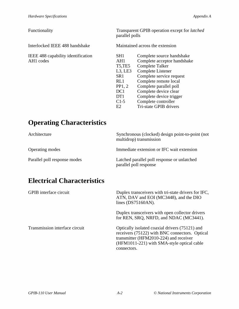
Functionality Transparent GPIB operation except for latchedparallel polls
Interlocked IEEE 488 handshake Maintained across the extension
IEEE 488 capability identification SH1 Complete source handshakeAH1 codes AH1 Complete acceptor handshake
T5,TE5 Complete TalkerL3, LE3 Complete ListenerSR1 Complete service requestRL1 Complete remote localPP1, 2 Complete parallel pollDC1 Complete device clearDT1 Complete device triggerC1-5 Complete controllerE2 Tri-state GPIB drivers
Operating Characteristics
Architecture Synchronous (clocked) design point-to-point (notmultidrop) transmission
Operating modes Immediate extension or IFC wait extension
Parallel poll response modes Latched parallel poll response or unlatchedparallel poll response
Electrical Characteristics
GPIB interface circuit Duplex transceivers with tri-state drivers for IFC,ATN, DAV and EOI (MC3448), and the DIOlines (DS75160AN).
Duplex transceivers with open collector driversfor REN, SRQ, NRFD, and NDAC (MC3441).
Transmission interface circuit Optically isolated coaxial drivers (75121) andreceivers (75122) with BNC connectors. Opticaltransmitter (HFM2010-224) and receiver(HFM1011-221) with SMA-style optical cableconnectors.

Appendix A Hardware Specifications
© National Instruments Corporation A-3 GPIB-110 User Manual
Table A-2. Electrical Specifications
Characteristic Specification
Power Supply Unit 100 to 120 VAC, 50 to 50 Hz, or220 to 240 VAC, 50 to 60 Hz
Maximum CurrentRequirement
100 to 120 VAC, 200mA220 to 240 VAC, 100mA
Fuse Rating and Type 100 to 120 VAC, 300mA, 250V, SLOBLO, UL/CSA Approved220 to 240 VAC, 200mA, 250V, SLOBLO, IEC Approved
Caution: Replacement fuses should be the correct type and rating. Refer to the sectionentitled, Electrical Characteristics, for fuse information.
Environmental CharacteristicsOperating temperature 0° to 45° C
Humidity 5% to 95% non-condensing conditions
FCC Class A verified
Physical CharacteristicsCase style CS2
Size 3.5 in. by 8.5 in. by 13 in. (89 mm by 216 mm by330 mm)
Case material UL94V-0 flame-retardant polystyrene Dow60875F or equivalent
Rack-mounting Single or dual kits available
GPIB cable National Instruments part number 763061-xx orequivalent
Transmission cable Belden V.P.C. part number 95680 75 Ω coaxialcable 9248, RG-6/U type with male BNCconnectors.
Optical Cable Corporation fiber optic cableA02-030D-C4DB/900.3 mm cable diameter.Flame-retardant PVC jacket.Graded, 100/140 micron core/clad with aminimum NA of 0.28.850 nm operating wavelength.4 dB/km attenuation.100 MHz-km fiber bandwidth.Duplex style, terminated with aluminumSMA-style connectors.
© National Instruments Corporation B-1 GPIB-110 User Manual
Appendix BMultiline Interface Messages
This appendix lists the multiline interface messages and describes the mnemonics and messagesthat correspond to the interface functions. These functions include initializing the bus,addressing and unaddressing devices, and setting device modes for local or remote programming.The multiline interface messages are IEEE 488-defined commands that are sent and receivedwith ATN TRUE.
For more information on these messages, refer to the ANSI/IEEE Standard 488-1987, IEEEStandard Digital Interface for Programmable Instrumentation.
Multiline Interface Messages Appendix B
GPIB-110 User Manual B-2 © National Instruments Corporation
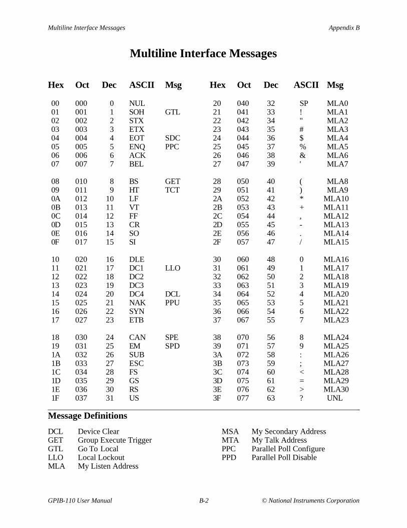
Multiline Interface Messages
Hex Oct Dec ASCII Msg Hex Oct Dec ASCII Msg
00 000 0 NUL 20 040 32 SP MLA001 001 1 SOH GTL 21 041 33 ! MLA102 002 2 STX 22 042 34 " MLA203 003 3 ETX 23 043 35 # MLA304 004 4 EOT SDC 24 044 36 $ MLA405 005 5 ENQ PPC 25 045 37 % MLA506 006 6 ACK 26 046 38 & MLA607 007 7 BEL 27 047 39 ' MLA7
08 010 8 BS GET 28 050 40 ( MLA809 011 9 HT TCT 29 051 41 ) MLA90A 012 10 LF 2A 052 42 * MLA100B 013 11 VT 2B 053 43 + MLA110C 014 12 FF 2C 054 44 , MLA120D 015 13 CR 2D 055 45 - MLA130E 016 14 SO 2E 056 46 . MLA140F 017 15 SI 2F 057 47 / MLA15
10 020 16 DLE 30 060 48 0 MLA1611 021 17 DC1 LLO 31 061 49 1 MLA1712 022 18 DC2 32 062 50 2 MLA1813 023 19 DC3 33 063 51 3 MLA1914 024 20 DC4 DCL 34 064 52 4 MLA2015 025 21 NAK PPU 35 065 53 5 MLA2116 026 22 SYN 36 066 54 6 MLA2217 027 23 ETB 37 067 55 7 MLA23
18 030 24 CAN SPE 38 070 56 8 MLA2419 031 25 EM SPD 39 071 57 9 MLA251A 032 26 SUB 3A 072 58 : MLA261B 033 27 ESC 3B 073 59 ; MLA271C 034 28 FS 3C 074 60 < MLA281D 035 29 GS 3D 075 61 = MLA291E 036 30 RS 3E 076 62 > MLA301F 037 31 US 3F 077 63 ? UNL
Message Definitions
DCL Device ClearGET Group Execute TriggerGTL Go To LocalLLO Local LockoutMLA My Listen Address
MSA My Secondary AddressMTA My Talk AddressPPC Parallel Poll ConfigurePPD Parallel Poll Disable
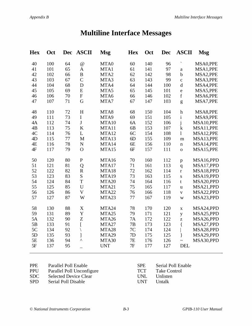
Appendix B Multiline Interface Messages
© National Instruments Corporation B-3 GPIB-110 User Manual
Multiline Interface Messages
Hex Oct Dec ASCII Msg Hex Oct Dec ASCII Msg
40 100 64 @ MTA0 60 140 96 ` MSA0,PPE41 101 65 A MTA1 61 141 97 a MSA1,PPE42 102 66 B MTA2 62 142 98 b MSA2,PPE43 103 67 C MTA3 63 143 99 c MSA3,PPE44 104 68 D MTA4 64 144 100 d MSA4,PPE45 105 69 E MTA5 65 145 101 e MSA5,PPE46 106 70 F MTA6 66 146 102 f MSA6,PPE47 107 71 G MTA7 67 147 103 g MSA7,PPE
48 110 72 H MTA8 68 150 104 h MSA8,PPE49 111 73 I MTA9 69 151 105 i MSA9,PPE4A 112 74 J MTA10 6A 152 106 j MSA10,PPE4B 113 75 K MTA11 6B 153 107 k MSA11,PPE4C 114 76 L MTA12 6C 154 108 l MSA12,PPE4D 115 77 M MTA13 6D 155 109 m MSA13,PPE4E 116 78 N MTA14 6E 156 110 n MSA14,PPE4F 117 79 O MTA15 6F 157 111 o MSA15,PPE
50 120 80 P MTA16 70 160 112 p MSA16,PPD51 121 81 Q MTA17 71 161 113 q MSA17,PPD52 122 82 R MTA18 72 162 114 r MSA18,PPD53 123 83 S MTA19 73 163 115 s MSA19,PPD54 124 84 T MTA20 74 164 116 t MSA20,PPD55 125 85 U MTA21 75 165 117 u MSA21,PPD56 126 86 V MTA22 76 166 118 v MSA22,PPD57 127 87 W MTA23 77 167 119 w MSA23,PPD
58 130 88 X MTA24 78 170 120 x MSA24,PPD59 131 89 Y MTA25 79 171 121 y MSA25,PPD5A 132 90 Z MTA26 7A 172 122 z MSA26,PPD5B 133 91 [ MTA27 7B 173 123 MSA27,PPD5C 134 92 \ MTA28 7C 174 124 | MSA28,PPD5D 135 93 ] MTA29 7D 175 125 MSA29,PPD5E 136 94 ^ MTA30 7E 176 126 ~ MSA30,PPD5F 137 95 _ UNT 7F 177 127 DEL
PPE Parallel Poll EnablePPU Parallel Poll UnconfigureSDC Selected Device ClearSPD Serial Poll Disable
SPE Serial Poll EnableTCT Take ControlUNL UnlistenUNT Untalk

Multiline Interface Messages Appendix B
GPIB-110 User Manual B-4 © National Instruments Corporation
Interface Message Reference List
Local Messages Received (by interface functions)
Mnemonic Message Interface Function(s)
gts go to standby Cist individual status qualifier PPlon listen only L, LE[lpe] local poll enable PPltn listen L, LElun local unlisten L, LEnba new byte available SHpon power on SH, AH, T, TE, L, LE, SR,
RL, PP, Crdy ready AHrpp request parallel poll Crsc request system control Crsv request service SRrtl return to local RLsic send interface clear Csre send remote enable Ctca take control asynchronously Ctcs take control synchronously AH, Cton talk only T, TE
Remote Messages Received
Mnemonic Message Interface Function(s)
ATN attention SH, AH, T, TE, L, LE, PP, CDAB data byte (via L, LE)DAC data accepted SHDAV data valid AHDCL device clear DCEND end (via L, LE)GET group execute trigger DTGTL go to local RLIDY identify L, LE, PPIFC interface clear T, TE, L, LE, CLLO local lockout RLMLA my listen address L, LE, RL[MLA] my listen address TMSA or [MSA] my secondary address TE, LEMTA my talk address T, TE[MTA] my talk address LOSA other secondary address TEOTA other talk address T, TEPCG primary command group TE, LE, PPPPC parallel poll configure PP[PPD] parallel poll disable PP[PPE] parallel poll enable PP

Appendix B Multiline Interface Messages
© National Instruments Corporation B-5 GPIB-110 User Manual
Interface Message Reference List (Continued)
Remote Messages Received (Continued)
Mnemonic Message Interface Function(s)
PPRn parallel poll response n (via C)PPU parallel poll unconfigure PP
Remote Messages Sent
Mnemonic Message Interface Function(s)
REN remote enable RLRFD ready for data SHRQS request service (via L, LE)[SDC] selected device clear DCSPD serial poll disable T, TESPE serial poll enable T, TESRQ service request (via C)STB status byte (via L, LE)TCT or [TCT] take control CUNL unlisten L, LEATN attention CDAB data byteDAC data accepted AHDAV data valid SHDCL device clear (via C)END end (via T)GET group execute trigger (via C)GTL go to local (via C)IDY identify CIFC interface clear CLLO local lockout (via C)MLA or [MLA] my listen address (via C)MSA or [MSA] my secondary address (via C)MTA or [MTA] my talk address (via C)OSA other secondary address (via C)OTA other talk address (via C)PCG primary command group (via C)PPC parallel poll configure (via C)[PPD] parallel poll disable (via C)[PPE] parallel poll enable (via C)PPRn parallel poll response n PPPPU parallel poll unconfigure (via C)REN remote enable CRFD ready for data AHRQS request service T, TE[SDC] selected device clear (via C)SPD serial poll disable (via C)SPE serial poll enable (via C)SRQ service request SR

Multiline Interface Messages Appendix B
GPIB-110 User Manual B-6 © National Instruments Corporation
Interface Message Reference List (Continued)
Remote Messages Sent (Continued)
Mnemonic Message Interface Function(s) STB status byte (via T, TE)TCT take control (via C)UNL unlisten (via C)UNT untalk (via C)
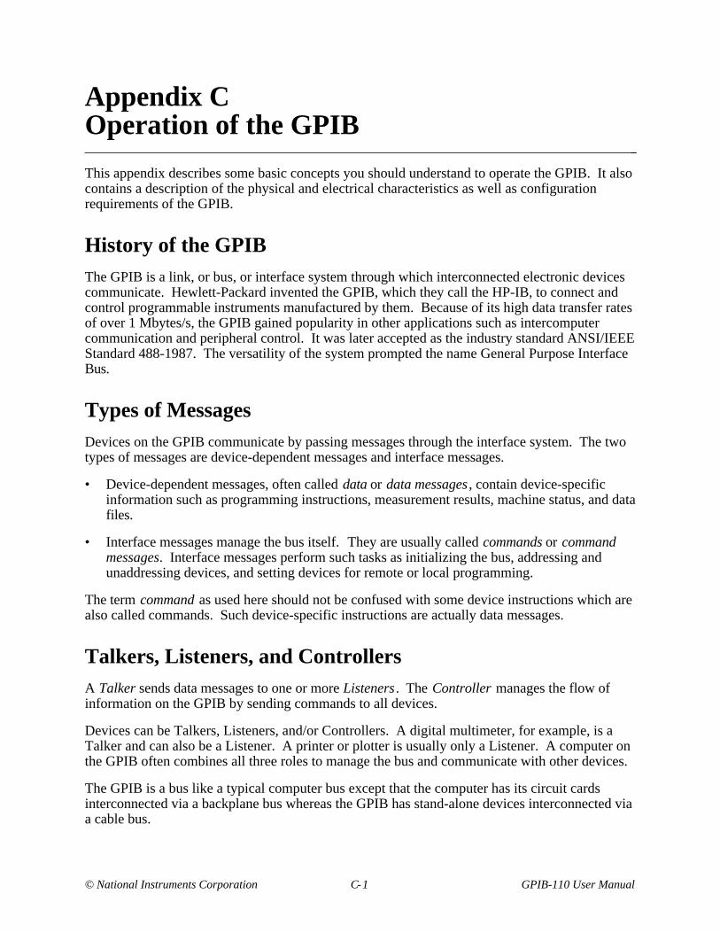
© National Instruments Corporation C-1 GPIB-110 User Manual
Appendix COperation of the GPIB
This appendix describes some basic concepts you should understand to operate the GPIB. It alsocontains a description of the physical and electrical characteristics as well as configurationrequirements of the GPIB.
History of the GPIBThe GPIB is a link, or bus, or interface system through which interconnected electronic devicescommunicate. Hewlett-Packard invented the GPIB, which they call the HP-IB, to connect andcontrol programmable instruments manufactured by them. Because of its high data transfer ratesof over 1 Mbytes/s, the GPIB gained popularity in other applications such as intercomputercommunication and peripheral control. It was later accepted as the industry standard ANSI/IEEEStandard 488-1987. The versatility of the system prompted the name General Purpose InterfaceBus.
Types of MessagesDevices on the GPIB communicate by passing messages through the interface system. The twotypes of messages are device-dependent messages and interface messages.
• Device-dependent messages, often called data or data messages , contain device-specificinformation such as programming instructions, measurement results, machine status, and datafiles.
• Interface messages manage the bus itself. They are usually called commands or commandmessages. Interface messages perform such tasks as initializing the bus, addressing andunaddressing devices, and setting devices for remote or local programming.
The term command as used here should not be confused with some device instructions which arealso called commands. Such device-specific instructions are actually data messages.
Talkers, Listeners, and ControllersA Talker sends data messages to one or more Listeners . The Controller manages the flow ofinformation on the GPIB by sending commands to all devices.
Devices can be Talkers, Listeners, and/or Controllers. A digital multimeter, for example, is aTalker and can also be a Listener. A printer or plotter is usually only a Listener. A computer onthe GPIB often combines all three roles to manage the bus and communicate with other devices.
The GPIB is a bus like a typical computer bus except that the computer has its circuit cardsinterconnected via a backplane bus whereas the GPIB has stand-alone devices interconnected viaa cable bus.

Operation of the GPIB Appendix C
GPIB-110 User Manual C-2 © National Instruments Corporation
The role of the GPIB Controller can also be compared to the role of the CPU of a computer, buta better analogy is to the switching center of a city telephone system.
The switching center (Controller) monitors the communications network (GPIB). When thecenter (Controller) notices that a party (device) wants to make a call (send a data message), itconnects the caller (Talker) to the receiver (Listener).
The Controller usually addresses a Talker and a Listener before the Talker can send its messageto the Listener. After the message is transmitted, the Controller usually unaddresses bothdevices.
Some bus configurations do not require a Controller. For example, one device may only be aTalker (called a Talk-only device) and there may be one or more Listen-only devices.
A Controller is necessary when the active or addressed Talker or Listener must be changed. TheController function is usually handled by a computer.
With the GPIB interface board, your personal computer plays all three roles.
• Controller–manages the GPIB
• Talker–sends data
• Listener–receives data
Controller-In-Charge and System Controller
Although there can be multiple Controllers on the GPIB, only one Controller at a time is ActiveController or Controller-in-Charge (CIC). Active control can be passed from the current ActiveController to an idle Controller. Only one device on the bus, the System Controller, can makeitself the CIC.
GPIB Signals and Lines
The interface bus consists of 16 signal lines and 8 ground return or shield drain lines. The 16signal lines are divided into three groups:
• Eight data lines
• Three handshake lines
• Five interface management lines
Appendix C Operation of the GPIB
© National Instruments Corporation C-3 GPIB-110 User Manual
Figure C-1 shows the arrangement of these signals on the GPIB cable connector.
DIO1*DIO2*DIO3*DIO4*
EOI*DAV*
NRFD*NDAC*
IFC*SRQ*ATN*
SHIELD
DIO5*DIO6*DIO7*DIO8*REN*GND (Twisted Pair with DAV*)GND (Twisted Pair with NRFD*)GND (Twisted Pair with NDAC*)GND (Twisted Pair with IFC*)GND (Twisted Pair with SRQ*)GND (Twisted Pair with ATN*)SIGNAL GROUND
123456789101112
131415161718192021222324
Figure C-1. GPIB Cable Connector
Data Lines
The eight data lines, DIO1 through DIO8, carry both data and command messages. Allcommands and most data use the 7-bit ASCII or ISO code set, in which case the 8th bit, DIO8, isunused or used for parity.
The GPIB command messages are listed in Appendix B, Multiline Interface Messages .
Handshake Lines
Three lines asynchronously control the transfer of message bytes among devices. The process iscalled a three-wire interlocked handshake and it guarantees that message bytes on the data linesare sent and received without transmission error.
Operation of the GPIB Appendix C
GPIB-110 User Manual C-4 © National Instruments Corporation
NRFD (not ready for data)
NRFD indicates when a device is ready or not ready to receive a message byte. The line isdriven by all devices when receiving commands and by Listeners when receiving data messages.
NDAC (not data accepted)
NDAC indicates when a device has or has not accepted a message byte. The line is driven by alldevices when receiving commands and by Listeners when receiving data messages.
DAV (data valid)
DAV tells when the signals on the data lines are stable (valid) and can be accepted safely bydevices. The Controller drives DAV when sending commands and the Talker drives it whensending data messages.
The way in which NRFD and NDAC are used by the receiving device is called the AcceptorHandshake. Likewise, the sending device uses DAV in the Source Handshake.
Interface Management Lines
Five lines are used to manage the flow of information across the interface.
ATN (attention)
The Controller drives ATN true when it uses the data lines to send commands and false when itallows a Talker to send data messages.
IFC (interface clear)
The System Controller drives the IFC line to initialize the bus to become CIC.
REN (remote enable)
The System Controller drives the REN line, which is used to place devices in remote or localprogram mode.
SRQ (service request)
Any device can drive the SRQ line to asynchronously request service from the CIC with the SRQline.
EOI (end or identify)
The EOI line has two purposes. The Talker uses it to mark the end of a message string. The CICuses it to tell devices to identify their responses in a parallel poll.

Appendix C Operation of the GPIB
© National Instruments Corporation C-5 GPIB-110 User Manual
Physical and Electrical Characteristics
Devices are usually connected with a cable assembly consisting of a shielded 24-conductor cablewith both a plug and receptacle at each end. This design allows devices to be connected in eithera linear or a star configuration, or a combination of the two. See Figures C-2 and C-3.
GPIB Cables
Device A
Device C
Device B
Figure C-2. Linear Configuration of the GPIB Devices
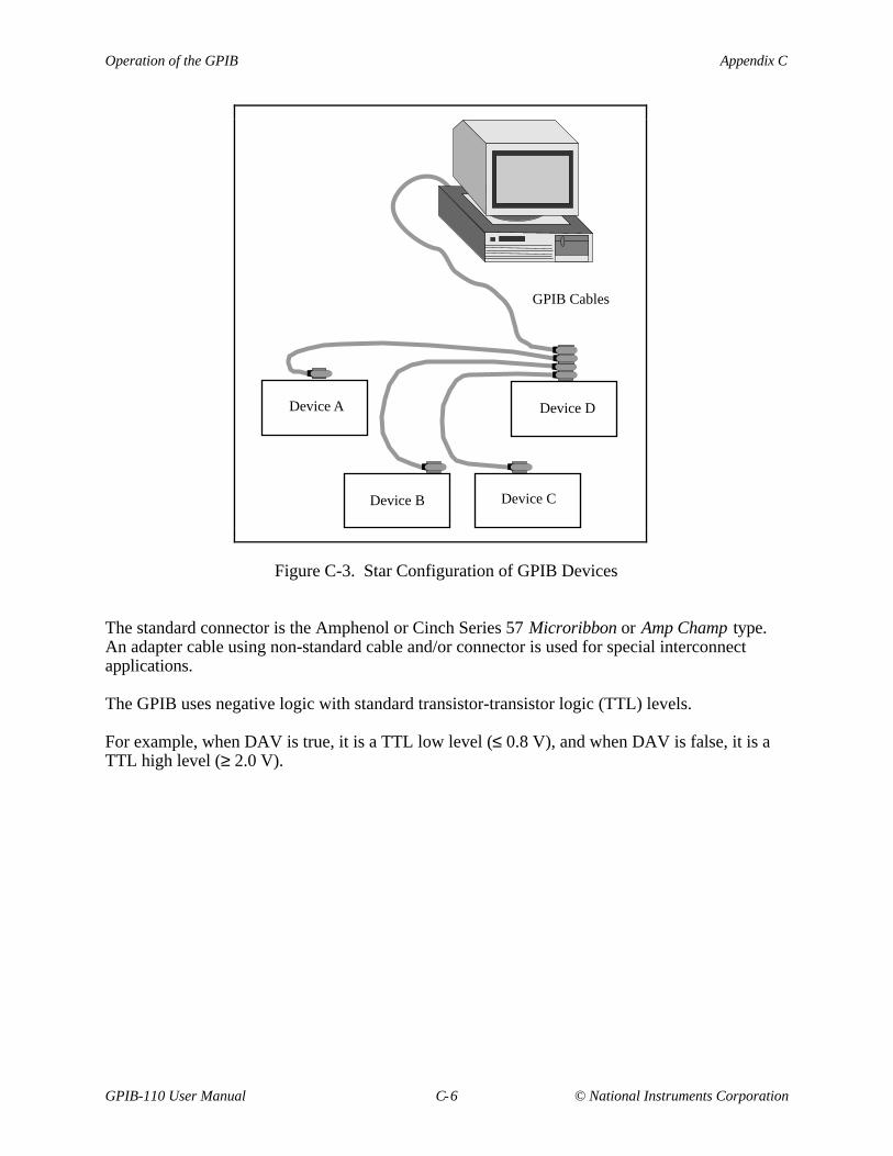
Operation of the GPIB Appendix C
GPIB-110 User Manual C-6 © National Instruments Corporation
GPIB Cables
Device A
Device C
Device D
Device B
Figure C-3. Star Configuration of GPIB Devices
The standard connector is the Amphenol or Cinch Series 57 Microribbon or Amp Champ type.An adapter cable using non-standard cable and/or connector is used for special interconnectapplications.
The GPIB uses negative logic with standard transistor-transistor logic (TTL) levels.
For example, when DAV is true, it is a TTL low level (≤ 0.8 V), and when DAV is false, it is aTTL high level (≥ 2.0 V).

Appendix C Operation of the GPIB
© National Instruments Corporation C-7 GPIB-110 User Manual
Configuration Restrictions: The Role of Extenders andExpanders
To achieve the high data transfer rate that the GPIB is designed for, the physical distancebetween devices and the number of devices on the bus is limited.
The following restrictions are typical:
• A maximum separation of 4 m between any two devices and an average separation of 2 mover the entire bus.
• A maximum total cable length of 20 m.
• No more than 15 devices connected to each bus, with at least two-thirds of the devices turnedon.
You can usually connect a cluster of lab instruments without exceeding these restrictions.However, many applications require longer cable spans or additional loading.
From the time the GPIB was invented, the need existed for bus extenders and expanders(repeaters). Extenders connect two separate buses via a transmission medium, and the distancebetween the buses can be quite long. Expanders or repeaters generally buffer one bus from anadjacent bus that doubles the total cable and loading limits.
The GPIB-110 is a serial extender that uses either low-cost coaxial cable or high-performanceelectrically isolated fiber-optic cable as its transmission medium. The GPIB-110 samples GPIBsignals on each bus to which it is connected, serializes the information encoded in small packets,and transmits the packets to the remote side. Separate packets are sent for each message or bytehandshaking, maintaining GPIB synchronization between both connected buses.
The GPIB-110 uses a handshake protocol that allows it to maintain optimum communicationbetween both extenders in the link. In addition, a low-bit cyclical redundancy code is used todetect serial transmission errors. The GPIB-110 recovers automatically from detected errors.
National Instruments also manufactures a parallel extender, the GPIB-130. This extender relaysthe instantaneous status of all GPIB signals over an RS-422 compatible cable and allows up to a300 m extension.
The National Instruments GPIB-120A is a high-speed GPIB expander that allows up to 14additional devices to be connected to the bus and 20 m of cable length to be added to the system.In addition, optical isolation is provided between the two connected GPIBs to prevent groundloop and noise problems. Only one GPIB-120A is required per expansion.

© National Instruments Corporation D-1 GPIB-110 User Manual
Appendix DCustomer Communication
For your convenience, this appendix contains forms to help you gather the information necessaryto help us solve technical problems you might have as well as a form you can use to comment onthe product documentation. Filling out a copy of the Technical Support Form before contactingNational Instruments helps us help you better and faster.
National Instruments provides comprehensive technical assistance around the world. In the U.S.and Canada, applications engineers are available Monday through Friday from 8:00 a.m. to6:00 p.m. (central time). In other countries, contact the nearest branch office. You may faxquestions to us at any time.
Corporate Headquarters(512) 795-8248Technical support fax: (800) 328-2203
(512) 794-5678
Branch Offices Phone Number Fax NumberAustralia (03) 879 9422 (03) 879 9179Austria (0662) 435986 (0662) 437010-19Belgium 02/757.00.20 02/757.03.11Denmark 45 76 26 00 45 76 71 11Finland (90) 527 2321 (90) 502 2930France (1) 48 14 24 00 (1) 48 14 24 14Germany 089/741 31 30 089/714 60 35Italy 02/48301892 02/48301915Japan (03) 3788-1921 (03) 3788-1923Netherlands 03480-33466 03480-30673Norway 32-848400 32-848600Spain (91) 640 0085 (91) 640 0533Sweden 08-730 49 70 08-730 43 70Switzerland 056/20 51 51 056/20 51 55U.K. 0635 523545 0635 523154

Technical Support Form___________________________________________________
Photocopy this form and update it each time you make changes to your software or hardware, and use the completedcopy of this form as a reference for your current configuration. Completing this form accurately before contactingNational Instruments for technical support helps our applications engineers answer your questions more efficiently.
If you are using any National Instruments hardware or software products related to this problem, include theconfiguration forms from their user manuals. Include additional pages if necessary.
Name
Company
Address
Fax ( ) Phone ( )
Computer brand Model Processor
Operating system
Speed MHz RAM M Display adapter
Mouse yes no Other adapters installed
Hard disk capacity M Brand
Instruments used
National Instruments hardware product model Revision
Configuration
National Instruments software product Version
Configuration
The problem is
List any error messages
The following steps will reproduce the problem

GPIB-110 Hardware and SoftwareConfiguration Form Record the settings and revisions of your hardware and software on the line to the right of each item. Updatethis form each time you revise your software or hardware configuration, and use this form as a reference foryour current configuration.
National Instruments Products
• GPIB-110 Revision
• Remote GPIB-110 Revision
• National Instruments GPIB Interface
• National Instruments Software
• Fiber Optic or Coax Cable or Both
• Length of cable
Other Products
• Computer Make and Model
• Operating System Version
• Number of GPIB Devices on Bus
• Other Boards in System
• GPIB Devices in System
• Other Cables in Systems
• Type and Manufacturer
• Length of cable

Documentation Comment Form
National Instruments encourages you to comment on the documentation supplied with our products. Thisinformation helps us provide quality products to meet your needs.
Title: GPIB-110 User Manual
Edition Date: August 1994
Part Number: 320052-01
Please comment on the completeness, clarity, and organization of the manual.
If you find errors in the manual, please record the page numbers and describe the errors.
Thank you for your help.
Name
Title
Company
Address
Phone ( )
Mail to: Technical Publications Fax to: Technical PublicationsNational Instruments Corporation National Instruments Corporation6504 Bridge Point Parkway, MS 53-02 MS 53-02Austin, TX 78730-5039 (512) 794-5678

© National Instruments Corporation Glossary-1 GPIB-110 User Manual
Glossary___________________________________________________
Prefix Meaning Value
n- nano- 10-9
µ- micro- 10-6
m- milli- 10-3
k- kilo- 103
M- mega- 106
° degrees≥ is greater than or equal to≤ is less than or equal toΩ ohms% percent
A amperesAC Active ControllerAC alternating currentASCII American Standard Code for Information ExchangeBNC refers to coaxial cable connectorC CelsiusCIC Controller-In-ChargeCPU central processing unitdB decibelsDC direct currentEOI End-or-IdentifyERR Error bitFCC Federal Communications CommissionFO fiber opticGPIB General Purpose Interface BusHP Hewlett-PackardHz hertzIDY Identify messageIFC Interface Clearin. inchesISO International Standards Organizationkbytes 1,000 bytesLAC Local Active ControllerLED light-emitting diodeLOC Local LEDLS Local Source state

Glossary
GPIB-110 User Manual Glossary-2 © National Instruments Corporation
LSC Local System Controllerm metersMB megabytes of memoryMbytes 1,000,000 bytesNA numerical aperturePPR Parallel Poll ResponsePVC PolyvinylchlorideRAC Remote Active ControllerREM Remote LEDRS Remote Source stateRSC Remote System Controllers secondsTTL transistor-transistor logicV voltsVAC volts alternating currentW watts

© National Instruments Corporation Index-1 GPIB-110 User Manual
Index
A
abbreviations and acronyms used in the manual, vi
Active ControllerLEDs for, 2-3theory of operation, 3-3
ATN line (attention), C-4
C
cablescoaxial cable setup, 2-6fiber optic cable setup, 2-7GPIB cable connector (illustration), C-3jumper settings for selecting, 2-6overcoming length restrictions, 1-3
COAX connector, 2-4coaxial cable
self-test mode, 2-13setting up, 2-6
commands or command messages, C-1configuration
cable selection, 2-6coaxial cable setup, 2-6extension modes, 2-8 to 2-9fiber optic cable setup, 2-7grounding configuration, 2-1 to 2-2IFC Wait Mode, 2-9Immediate Extension Mode, 2-8master switch setting, 2-7Parallel Poll Response modes, 2-9 to 2-10role of extenders and expanders,
C-6 to C-7settings for configuration switch, 2-5system configuration specifications, A-1transmit clock, 2-8
configuration switchdefault settings, 2-5illustration of, 2-5location of, 2-4possible configurations for, 2-5
connectors and switches. See also jumpers.
COAX connector, 2-4coaxial cable setup, 2-6configuration switch, 2-4, 2-5
fiber optic cable setup, 2-7Fiber Optic Transmit Power setting, 2-7GPIB connector, 2-4IFC Wait Mode, 2-9Immediate Extension Mode, 2-8master switch setting, 2-7RCVR connector, 2-4on rear panel of GPIB-110, 2-4TRANS connector, 2-4
ControllersController-in-Charge, C-2role of Controller, C-2
customer support, vii
D
data direction control, 3-5data lines, C-3data or data messages, C-1DAV signal (data valid), C-4documentation
abbreviations used in the manual, viacronyms used in the manualrelated documentation
E
electrical specifications, A-2environmental specifications, A-3EOI, operation of, 3-5EOI line (end or identify), C-4equipment, optional, 1-4ERR LED, 2-3error detection and recovery for serial
communication, 3-7 to 3-8extenders and expanders
limitations on, C-7operation of, C-6 to C-7
extension circuitry, definition of, 3-1

Index
GPIB-110 User Manual Index-2 © National Instruments Corporation
extension modesIFC Wait Mode, 2-9Immediate Extension Mode, 2-8
F
fiber optic cableFiber Optic Transmit Power setting, 2-7self-test mode, 2-12setting up, 2-6
FO SIGNAL OK LED, 2-4front panel of GPIB-110, 2-3
G
GPIB-110 bus extender. See also operation of the GPIB; theory of operation.block diagram, 3-2contents of kit, 1-3definition of, 1-1description of, 1-1 to 1-3features of, 1-1illustration of, 1-1logical configuration (illustration), 1-2models of, 2-1optional equipment, 1-4physical configuration (illustration), 1-2physical restrictions on, C-6 to C-7
grounding configurationisolation of grounds, 2-1 to 2-2isolation selection (illustration), 2-2overview, 2-1
H
handshake linesDAV (data valid), C-4NDAC (not data accepted), C-4NRFD (not ready for data), C-4
Hewlett-Packard controllers, 2-13history of the GPIB, C-1
I
IFC line (interface clear), C-4
IFC Wait Mode, 2-9Immediate Extension Mode, 2-8installation. See also configuration.
connecting to Hewlett-Packardcontrollers, 2-13
front panel, 2-3mounting the GPIB-110, 2-11overview, 2-1power on, 2-11procedure for, 2-11rear panel, 2-4Self-Test mode, 2-11 to 2-12unpacking the GPIB-110, 1-4
interface management linesATN (attention), C-4EOI (end or identify), C-4IFC (interface clear), C-4REN (remote enable), C-4SRQ (service request), C-4
J
jumpers. See also connectors and switches.grounding isolation selection
(illustration), 2-2setting for cable selection, 2-6
L
Latched PPR mode, 2-11LEDs
for Active Controller, 2-3ERR, 2-3FO SIGNAL OK, 2-4LINK, 2-3LOC, 2-3PWR LED, 2-3REM, 2-3Serial Communication LEDs, 2-3for Source Handshake, 2-3for System Controller, 2-3
light emitting diodes. See LEDs.link establishment protocol, 3-6LINK LED, 2-3, 3-6Listeners, C-2LOC LED, 2-3local state, definition of, 2-3

Index
© National Instruments Corporation Index-3 GPIB-110 User Manual
M
Master Controller, preloading, 2-13master switch setting
Fiber Optic Transmit Power setting, 2-7overview, 2-7
messages. See also multiline interface messages.commands or command messages, C-1data or data messages, C-1
mounting the GPIB-110, 2-11multiline interface messages
interface message reference list,B-4 to B-6
list of, B-2 to B-3local messages received, B-4remote messages received, B-4 to B-5remote messages sent, B-5 to B-6
N
NDAC signal (not data accepted), C-4NRFD signal (not ready for data), C-4
O
operating characteristics, A-2operation of the GPIB. See also theory ofoperation.
configuration restrictions, C-6 to C-7GPIB signals
data lines, C-3GPIB cable connector (illustration), C-3handshake lines, C-3 to C-4interface management lines, C-4overview, C-2
history of the GPIB, C-1physical and electrical characteristics, C-5 to C-6role of extenders and expanders,
C-6 to C-7System Controller and Active
Controller, C-2Talkers, Listeners, and Controllers,
C-1 to C-2types of messages, C-1
P
packetspacket format, 3-7Receive Packet state, 3-7Transmit Packet state, 3-7
Parallel Poll Response modesANSI/IEEE Std. 488-1987 response
requirement, 2-9Latched PPR mode, 2-10mixed mode option, 2-10response time problems, 2-9theory of operation, 3-4 to 3-5Unlatched PPR mode, 2-10
performance characteristic specifications, A-1 to A-2
physical and electrical characteristicsdescription of, C-5 to C-6linear configuration of GPIB devices (illustration), C-5star configuration of GPIB devices (illustration), C-6
physical restrictions on configuration,C-6 to C-7
physical specifications, A-3power switch, 2-4powering on the GPIB-110
after installation, 2-11theory of operation, 3-2
preloading of Master Controller, 2-13PWR LED, 2-3
R
RCVR connector, 2-4rear panel of GPIB-110, 2-4Receive Packet state, 3-7Receive Wait state, 3-7REM LED, 2-3remote state, definition of, 2-3REN line (remote enable), C-4
S
Self-Test modecoaxial cable self-test, 2-12fiber optic cable self-test, 2-12

Index
GPIB-110 User Manual Index-4 © National Instruments Corporation
overview, 2-11serial communication circuitry
definition of, 3-1error detection and recovery, 3-7 to 3-8link establishment protocol, 3-6serial communication protocol
overview, 3-6packet format, 3-7Receive Packet state, 3-7Receive Wait state, 3-7Transmit Packet state, 3-7transmit synchronization state, 3-7
system timing and transmission clock,3-8
theory of operation, 3-6 to 3-7Serial Communication LEDs, 2-3signals
data lines, C-3GPIB cable connector (illustration), C-3handshake lines
DAV (data valid), C-4NDAC (not data accepted), C-4NRFD (not ready for data), C-4
interface management linesATN (attention), C-4EOI (end or identify), C-4IFC (interface clear), C-4REN (remote enable), C-4SRQ (service request), C-4
Source HandshakeLEDs for, 2-3theory of operation, 3-3 to 3-4
specificationselectrical, A-2environmental, A-3operating characteristics, A-2performance characteristics, A-1 to A-2physical, A-3system configuration, A-1
SRQ, operation of, 3-5SRQ line (service request), C-4switches. See connectors and switches.system configuration specifications, A-1System Controller
Controller-in-Charge, C-2LEDs for, 2-3theory of operation, 3-3
system timing and transmission clock forserial communication, 3-8
T
Talkers, Listeners, and Controllers,C-1 to C-2
technical support, viitheory of operation. See also operation of
the GPIB.Active Controller detection, 3-3block diagram of GPIB-110, 3-2data direction control, 3-5EOI, 3-5overview, 3-1parallel polling, 3-4 to 3-5powering on the GPIB-110, 3-2serial communication circuitry
error detection and recovery,3-7 to 3-8
link establishment protocol, 3-6system timing and transmission clock, 3-8
serial communication protocoloverview, 3-6packet format, 3-7Receive Packet state, 3-7Receive Wait state, 3-7Transmit Packet state, 3-7transmit synchronization state, 3-7
Source Handshake detection, 3-3 to 3-4SRQ, 3-5System Controller detection, 3-3
TRANS connector, 2-4transmit clock
configuring, 2-8system timing for serial communication, 3-3values versus cable length (table), 2-8
Transmit Packet state, 3-7Transmit Synchronization state, 3-7
U
Unlatched PPR mode, 2-10unpacking the GPIB-110, 1-4