
Arc Problems in Intercity Buses and Solution Studies of...
15
1009 1. Introduction Not more one or two decades ago, most of vehicles have only a few electrical systems such as ignition system, alternator, battery, lights, wiper, radio (optional) and air conditioner (optional). There were a few fuses, a few relays and short wiring harness to operate them. However modern vehicles have sophisticated and integrated systems such as Power train (Engine, Gearbox and Brake controllers) system, Safety (Active Brake assistance, Air-Cushion, Night and rear view system, Active or Dynamic lighting) system, Comfort (Automated HVAC, Cruise control system, Navigation, Park assistance, central locking and anti-theft) systems, Entertainment (Audio-Video player, CD/DVD player, Satellite receiver) systems which turned the vehicles to a vehicle like space shuttles. Each system has sub-systems and enormous number of detectors, sensors, actuators and controllers in a comprehensive structure. Furthermore, systems communicate with related ones via a common protocol like CAN Bus for proper operation. Arc Problems in Intercity Buses and Solution Studies of a Real Problem Reşit ERÇETIN 1 Hamdi Emre BAĞIRAN 2 Abstract Although modern vehicles are equipped with special electronic controller similar to programmable logic controller (PLC) to reduce wiring harness and relays, switching elements have found more and more place in vehicles with the increase of electronic circuits and safety requirements like every aspect of industry. In spite of its wide use, relays have some disadvantages because of being an electromechanical part. Limited mechanical and electrical lifetime, influence from environmental conditions such as ambient temperature, humidity, dust and contaminant gases, arc discharge between contacts and subsequently material transfer and erosion on contact surface are some of them. The main aim of manufacturers and consumers of relay is to remove these disadvantages and subsequently to increase efficiency of relays. In this study, DC relays which uses automotive applications, arc and arc caused a real problem belongs to an intercity bus electrical system will be mentioned. Keywords:Arc problem, PLC,Electronic controller 1 Department of Electricity and Energy, Electricity Programme, Anadolu Bil Vocational School of Higher Education, Istanbul Aydın University, [email protected] 2 Department of Electricity and Energy, Electricity Programme, Anadolu Bil Vocational School of Higher Education, Istanbul Aydın University, [email protected] Doi: 10.17932/ IAU.IJEMME.m.21460604.2015.5/4.1009-1023
-
Upload
phungkhanh -
Category
Documents
-
view
221 -
download
1
Transcript of Arc Problems in Intercity Buses and Solution Studies of...

1009
1. IntroductionNot more one or two decades ago, most of vehicles have only a few electrical systems such as ignition system, alternator, battery, lights, wiper, radio (optional) and air conditioner (optional). There were a few fuses, a few relays and short wiring harness to operate them. However modern vehicles have sophisticated and integrated systems such as Power train (Engine, Gearbox and Brake controllers) system, Safety (Active Brake assistance, Air-Cushion, Night and rear view system, Active or Dynamic lighting) system,
Comfort (Automated HVAC, Cruise control system, Navigation, Park assistance, central locking and anti-theft) systems, Entertainment (Audio-Video player, CD/DVD player, Satellite receiver) systems which turned the vehicles to a vehicle like space shuttles. Each system has sub-systems and enormous number of detectors, sensors, actuators and controllers in a comprehensive structure. Furthermore, systems communicate with related ones via a common protocol like CAN Bus for proper operation.
Arc Problems in Intercity Buses and Solution Studies of a Real Problem
Reşit ERÇETIN1 Hamdi Emre BAĞIRAN2
AbstractAlthough modern vehicles are equipped with special electronic controller similar to programmable logic controller (PLC) to reduce wiring harness and relays, switching elements have found more and more place in vehicles with the increase of electronic circuits and safety requirements like every aspect of industry.
In spite of its wide use, relays have some disadvantages because of being an electromechanical part. Limited mechanical and electrical lifetime, influence from environmental conditions such as ambient temperature, humidity, dust and contaminant gases, arc discharge between contacts and subsequently material transfer and erosion on contact surface are some of them.
The main aim of manufacturers and consumers of relay is to remove these disadvantages and subsequently to increase efficiency of relays. In this study, DC relays which uses automotive applications, arc and arc caused a real problem belongs to an intercity bus electrical system will be mentioned.
Keywords:Arc problem, PLC,Electronic controller
1 Department of Electricity and Energy, Electricity Programme, Anadolu Bil Vocational School of Higher Education, Istanbul Aydın University, [email protected] Department of Electricity and Energy, Electricity Programme, Anadolu Bil Vocational School of Higher Education, Istanbul Aydın University, [email protected]
Doi: 10.17932/ IAU.IJEMME.m.21460604.2015.5/4.1009-1023

1010
Arc Problems in Intercity Buses and Solution Studies of a Real Problem
The loads which have less consumption and have less voltage drop thanks to low current and short wires are directly driven by a switch or button except special case. But most of typical automotive applications such as motors, lights, HVAC (Heating, Ventilating and Air Conditioning), electronic control units, valve coils, audio-video systems, and window resistances are driven by relays. Toilet, front refrigerator and kitchenette should be added to typical automotive applications considering intercity buses. Automotive relays with a load voltage DC-12/24/42 V are generally designed and used to switch these automotive applications. Typical loads are with load currents from app. 3-5 A to 100-150 A.
For relay users, relay is just a switching element therefore relay manufacturer gives life expectancy of relay as number of opening-closing cycles of relay contacts. This life expectancy is given as electrical life expectancy and/or mechanical life expectancy.
Electrical life expectancy of a general purpose relay is rated to be 100,000 operations minimum roughly, while mechanical life expectancy may be one million, or more. The reason of difference is that electrical contact life is application dependent. When a contact switches a load of less than rated value, contact life can be significantly greater.
Figure 1: Main Applications of Switching Contacts1
Relay switching performances are affected by high ambient temperatures, humidity, dust and contaminant gases. A relay should be chosen according to these parameters as well as according to the parameters such as coil and contact voltage, contact load and type, electrical lifetime, enclosure type, temperature and vibration endurance, dimension, type of terminals.
2. Arc in Automotive RelaysArc is an electrical discharge which can be described as a passage of electrical current through a material which normally does not conduct electricity. The normally insulating air was transformed into a conductor, a process called electrical breakdown, and the sparks which we would see are a form of an electrical discharge. Normally air consists of neutral molecules of nitrogen, oxygen, and other gases, in which electrons are tightly bound to atomic nuclei. During the breakdown process, some of the negatively charged electrons are separated from their host atoms, leaving
1011INTERNATIONAL JOURNAL OF ELECTRONICS, MECHANICAL AND MECHATRONICS ENGINEERING Vol.5 Num.4 - 2015 (1009-1023)
Reşit ERÇETIN, Hamdi Emre BAĞIRAN
them with a positive charge. The negatively charged electrons and the positively charged atoms (known as positive ions) are then free to move separately under the influence of the applied voltage. Their movement constitutes an electrical current. The collection of ions and electrons is known as plasma, and one of its more important properties is that plasma can conduct electrical current.60
In a relay, arc is a spark ignition between contacts when they open and close produced by load current, inrush current or reverse (counter EMF) voltage.
Arc, which is serial, is one of the main influencing factors for the lifetime of switching elements. Dealing with arc in DC system is more difficult than AC system. Dissimilar with AC system, whose current crosses zero 100 times per second for 50 Hertz, DC remains continuous current. In AC system, the arc will extinguish at a zero crossover point. An ac load is easier to interrupt than a dc load because the ac interrupts itself each half cycle in spite of the fact that the max. voltage and current of the AC are 1.42 times greater than the equivalent DC for the same load voltage. Polarity changes prevent continued metal transfer in the same direction, a condition that often leads to early contact failure with DC loads.
Permanent arcs are produced mainly by DC current. Alternating current quenches the arc when the current crosses the zero point. Arcs are influenced by contact material, a reduction in arcing voltage and arcing current and the speed of the switching elements. When switching high DC loads, a larger contact gap and blow out magnet may be critical.
As current flows through the relay, power is dissipated in the contacts: P = I2 Rcontact + I2
Rarc . Rarc is the resistance of the arc that exists between the relay contacts during bounce. This power will dissipate as heat, raising the temperature of the contacts. Inrush currents expose the contacts to very high momentary power levels. The energy associated with inrush current may be sufficient to melt the contact surfaces. After bouncing, when the contacts come back together they can weld shut.
Inrush currents usually decrease rapidly to the steady state levels. Contact bounce, however, can subject the relay to multiple inrushes per activation, causing further damage.115
When a relay is powered, an arc ignites during the initial closure and subsequent contact bounce. Arcing causes contact erosion and unless precautions are taken, contact welding may result. At the very least, it can result in considerable contact damage. Therefore, the duration of the arc, the level of current and voltage are critical in determining relay life and reliability. High voltage power switching relays normally have stronger contacts materials (see section 1.1) because these metals are hard and have high melting temperatures which help to withstand the effects of arcing.
In an automotive, the existence of an arc requires a minimum current (IArc,min) <1A and a minimum arc voltage (VArc,min) ≥12VDC. There will be no arc if load current at a given minimum arc voltage is less than the minimum arc current for that voltage. Likewise, there will be no arc if load voltage (or counter emf) is less than the minimum arc voltage of the contact metal. These two arc characteristics depend on the contact materials and the

1012
Arc Problems in Intercity Buses and Solution Studies of a Real Problem
surrounding atmosphere (Table 2). An arc will ignite if both minimum arc voltage and current are exceeded.
Table 2: Minimum arc current and voltage for arc ignition in air [50]
Contact material UArc,min [V] IArc,min [A]Cu 13 0,43
Fe 13-15 0,35…0.55
C 20 0,01…0,03
Ag 12 0,4
Au 15 0,3
Ni 14 0,4…0,5
As shown in the table, an arc is an issue at any voltage higher than 12VDC and becomes more severe if voltage is higher. That’s why arc issues in buses, which have DC24V electrical system, are more important problems than arc problems in passenger cars.
Figure 2: Early deformation spots on a contact surface caused by arc
Let’s focus on following subjects which either cause an arc or make the effect of an arc more severe:
• Relay construction • Load types, Inrush current• Electrical connection • Environmental condition
2.1. Relay Construction Relays are electrically controlled devices that open or close electrical contacts to affect the operation of other devices in the same or different circuits. A relay’s most basic components are its coil, armature, and contacts. The armature spring keeps the contacts open when there is no voltage applied to the coil and opens the contacts when the voltage is removed from the coil. When voltage is applied to the coil, the armature starts to close and the armature spring force increases until the moveable contact touches the stationary contact. At this point the armature spring force is combined with the contact spring force. This total force increases until the armature is fully seated. When the voltage applied to the relay coil is above the minimum requirement, the pull force of the magnet is greater than the spring force and the relay operates normally.65
Arc duration is inversely but arc length is directly proportional to speed of the armature 66
Contact material is the material used in contacts and generally shown in chemistry formula, for example, AgNi represents silver-nickel alloy contacts. With modern production techniques, relay contacts are constructed as multi-layer contacts using plating, joining, or other method. The most common contact materials for automotive relays are alloys of silver such as AgNi and AgSnO2. In table-3, some contact materials and their properties is shown.
Contact materials are affected by sulfidation and oxidation. These layers of oxides, sulfides and other compounds can be formed on the surface of metal-contacts by absorption of gas molecules from the ambient atmosphere. The layers can increase the contact resistance which depends on the thickness of the layer, effective contact area and the specific

1013INTERNATIONAL JOURNAL OF ELECTRONICS, MECHANICAL AND MECHATRONICS ENGINEERING Vol.5 Num.4 - 2015 (1009-1023)
Reşit ERÇETIN, Hamdi Emre BAĞIRAN
resistance of the contact material. In order to get a reliable electric contact, the layer has to be removed by mechanical or electrical destruction. (Maybe the unique advantage of an arc is that destruction called electrical fritting.)
Material transfer of contacts refers to the transfer of the contact material from one contact to the other. When material transfer becomes serious the contact surface can be seen by eyes. Generally, material transfer of contacts is caused by the one-way flowing of the large current or the inrush current of the capacitive load and often happens in DC circuit. Generally it shows the protruding shape in the passive polarity and the concave shape in the positive polarity. The proper use of the contact protection circuit or the use of AgSnO contact which has better resistance against material transfer may reduce the material transfer of contacts.
Figure 3: Contact deformation caused by material transfer
In the left of Figure 3, a new contact is shown. In the right, accumulated material on contact surface is shown.
Compliance with RoHS (Restriction of
Hazardous Substances, the European Union Directive 2002/95/EC) is also a restriction for relay manufacturers in terms of materials. The directive restricts the use of certain hazardous substances, in electrical and electronic equipment including relays. Lead, Mercury, Cadmium, Hexavelent Chromium, PBBs and PBDEs are all subject to restriction. Relay manufacturers have to replace lead solder with tin solder, and AgCdO contacts with AgSn02.
Tabel 3: Main Contact Materials3
Contact Material Properties Main Applications
AgSnO2 (8-12)
AgSnO2 is a nontoxic material, compared to AgCdO, and has very good and stable welding resistance and arc erosion resistance. It has better erosion resistance than AgCdO in the current range of 500 ~ 3000 A, and shows better welding resistance than AgCdO and AgNi under lamp load and capacitive load. AgSnO2 shows low and stable resistance at DC lamp /motor loads (such as automobile relays). Under DC condition, AgSnO2 has less material transfer compared to AgCdO.
Widely used to AC contactors of large or medium capacity, and AC switches of large power (more than 50kW), DC contactors, AC/DC power relays, automobile equipment, and low-voltage circuit breakers of medium / small capacity. Excessively high surge current load (up to 120A)
AgNi (10-20)
The nickel grains in the material are of fiber structure. The material has high conductivity, and low and stable contact resistance; good resistance against welding and electric wear. Material transfer is very little under DC condition.
Widely used to AC or DC relays, command switches, contactors, optical controlled switches, temperature controllers and machine timers, etc.
AgNi (10-20)K
The welding resistance and arc erosion resistance are obviously improved by addition of a small quantity of additives.
Applied for high- and medium-current relays and medium- and low-power contactors.
2.2. Load Types Although the fact that automotive applications are highly complex and unfamiliar, classification of them is very familiar; typical loads are capacitive, inductive or resistive which can be found rarely in applications purely but mostly mixed. In table 4, typical loads and application examples are given.

1014
Arc Problems in Intercity Buses and Solution Studies of a Real Problem
Table 4: Typical loads and application examples4
Load Application Examples Current Curve
Res ist ive Loads
Heating
- Window heater
- Air/Water pre-heaters
Capacitive Loads
- Lamps8 (front, rear, lateral and interior lights)
- Filter capacitor (in ECU’s)
- Electronic ballast
Inductive Loads
- Motor and Pumps
(blowing fan, power window, central lock, pumps in HVAC system) - Solenoids (valves, relay coils)
Electrical loads are generally defined capacitive, inductive or resistive. All three types are usually present in real applications, but circuits with significant capacitive or inductive elements are more difficult to switch because of their stored energy.
As shown in table2, resistive loads consume certain current steadily. We can’t see any changes in current unless electrical or physical conditions change. But inductive and capacitive loads create instability for a while. One important feature of inductors is that they can store energy, like capacitors. Stored energy is;
The stored energy in the inductance induces a voltage that tends to maintain the current
till the energy of the inductance dissipates. The minus sign in VL means when the current decreases, the voltage across the inductor will tend to oppose the decrease. The storage of energy causes two main behaviors of inductors in DC system. One of them is current reaches its steady value with a time delay (see current diagram of solenoids in table 4) and other one is that it causes transient peak when interruption of coil power called reverse voltage or counter EMF.
On the contrary, capacitive loads cause time delay on voltage while capacitor is powered. At same time, initial (inrush) current which has effects on the contacts is very high transiently. The effect depends on the magnitude of the time constant of the circuit. Stored energy is;
E Stored=1/2CV2=e. A.E2.d2/2d=e. A.E2.d/2 [Joule]5
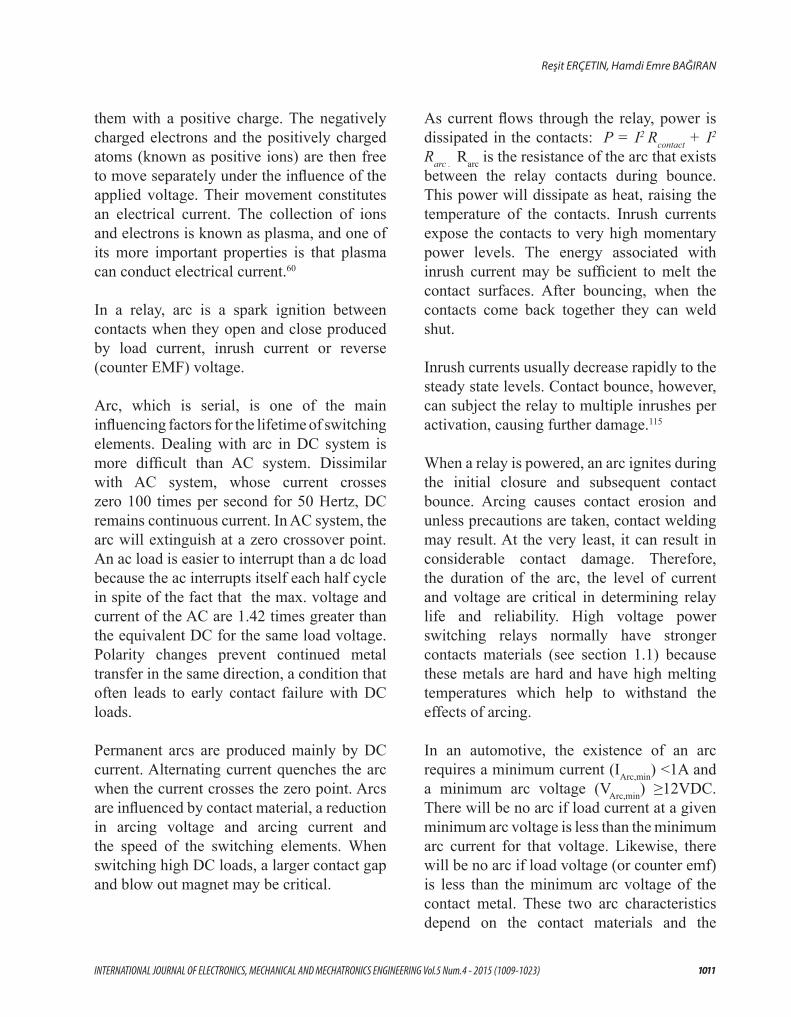
Inrush current can be explained that initial current higher than normal that flows instantaneously or transiently when system is switched on. Under high inrush conditions, contacts attempt to interrupt very high currents during the period of contact bounce resulting in a heavy arc being drawn that causes melting and welding of the contact metal. For examples, an electric motor will draw a very high current in the start process. This leads to a high make current as relay contacts close together. The load will vary according to motor size and design, but peaks can reach to 15 times of steady state current. Industrial relays will be operating at their design limits close to the normal value and will often not be suitable for the inrush current. Similarly, the resistance of cold filament bulbs is only about app. 10% of the value measured at operating temperature. Inrush current is therefore 10 times higher. A 5W bulb for example has an
1015INTERNATIONAL JOURNAL OF ELECTRONICS, MECHANICAL AND MECHATRONICS ENGINEERING Vol.5 Num.4 - 2015 (1009-1023)
Reşit ERÇETIN, Hamdi Emre BAĞIRAN
inrush power of more then 60W6. See figure below for inrush current of some automotive loads.
Inrush current do not affect only relays but also overcurrent protection devices like fuses. The selection of fuses and circuit breakers is made more complicated when high inrush currents must be tolerated. The overcurrent protection must react quickly to overload or short circuit but must not interrupt the circuit when the (usually harmless) inrush current flows.9
Figure 4 : Inrush currents of some automotive loads7
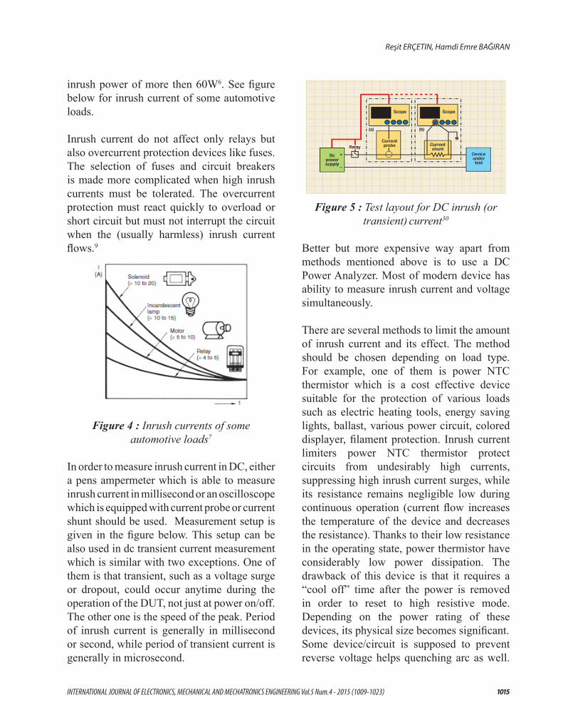
In order to measure inrush current in DC, either a pens ampermeter which is able to measure inrush current in millisecond or an oscilloscope which is equipped with current probe or current shunt should be used. Measurement setup is given in the figure below. This setup can be also used in dc transient current measurement which is similar with two exceptions. One of them is that transient, such as a voltage surge or dropout, could occur anytime during the operation of the DUT, not just at power on/off. The other one is the speed of the peak. Period of inrush current is generally in millisecond or second, while period of transient current is generally in microsecond.
Figure 5 : Test layout for DC inrush (or transient) current30
Better but more expensive way apart from methods mentioned above is to use a DC Power Analyzer. Most of modern device has ability to measure inrush current and voltage simultaneously.
There are several methods to limit the amount of inrush current and its effect. The method should be chosen depending on load type. For example, one of them is power NTC thermistor which is a cost effective device suitable for the protection of various loads such as electric heating tools, energy saving lights, ballast, various power circuit, colored displayer, filament protection. Inrush current limiters power NTC thermistor protect circuits from undesirably high currents, suppressing high inrush current surges, while its resistance remains negligible low during continuous operation (current flow increases the temperature of the device and decreases the resistance). Thanks to their low resistance in the operating state, power thermistor have considerably low power dissipation. The drawback of this device is that it requires a “cool off” time after the power is removed in order to reset to high resistive mode. Depending on the power rating of these devices, its physical size becomes significant.Some device/circuit is supposed to prevent reverse voltage helps quenching arc as well.

1016
Arc Problems in Intercity Buses and Solution Studies of a Real Problem
Some relay users connect a diode across the inductive load to prevent reverse voltage from reaching the contacts. When the relay contacts close, the stored energy of the inductance re-circulates through the diode, not through the arc.
Both inrush current and the reverse voltage will damage greatly the contacts and obviously shorten the life of the relay. But knowing the reason is important for choosing proper solution. If do so, most of arc problems will be overcome at first.
2.3. Electrical ConnectionIf working with high current or capacitive/ inductive loads which can ignite arc easily, arc ignition or increasing the negative effect of the arc will be unavoidable because of improper connection.
Depending on practical connection diagram, in some applications, like in side figure, reverse voltage flows over contacts and causes an arc. As mentioned in Section 2.2, inductive loads cause reverse voltage produced when the coil is de-energized. The stored energy (E=1/2 LI2) in a coil induces a voltage (VL) which depends on its inductance in Henry (L) and the rate of change of current in amperes per second (dI/dt). Unless any precaution is taken, reverse voltage can cause the arc as well as conducted im-munity problem which is one of the most difficult problems in the buses.
Although the re-sult on the con-tacts is same, it
should be clarified that arc caused by reverse (counter EMF) voltage is different from nor-mal arc. While the source of the arc is gen-erally normal or inrush current of load, the source of the arc caused by reverse voltage is counter emf produced by relay coils or induc-tive loads. Normal arc occurs while contacts open or close, the arc caused by reverse volt-age occurs while coil is de-energized. Thus, solution studies should be focused on these features accordingly. Coil suppression device or circuit is generally located in parallel with relay coil. (Sometimes it’s in parallel with the switch used to control the relay but normally not preferred because of less efficiency.) Arc quenching device or circuit is generally locat-ed in parallel with contact or load.
Working conditions such as on-off time and switching frequency can cause early contact failure. Therefore these parameters should be considered accordingly. In the contact circuit of the relay, when the lead wire with more than 10m length is used, the inrush current will be generated due to the capacitance in the lead wire.
2.4. Environmental ConditionIn terms of surrounding, every relays have some limitations to work in an environment. These environmental conditions such as temperature, humidity, dust, sulfur gases (SO2, H2S etc.) or organic gases, salty and acidic air have significant adverse effect on relays. They can not only affect the switching performance of relay but also can increase the magnitude of arcs and its effect. Under same electrical condition, a relay can have longer switching life under gentle environmental conditions than a relay under harsh environmental conditions. Similarly, the magnitude of an arc and its effect will be more severe in a relay under harsh environmental conditions.

1017INTERNATIONAL JOURNAL OF ELECTRONICS, MECHANICAL AND MECHATRONICS ENGINEERING Vol.5 Num.4 - 2015 (1009-1023)
Reşit ERÇETIN, Hamdi Emre BAĞIRAN
When a relay is used in an atmosphere high in humidity to switch a load which easily produces an arc, the NOx created by the arc and the water absorbed from outside the relay can combine to produce nitric acid. This corrodes the internal metal parts and adversely affects operation. The relay should not be used in the environment where the humidity is beyond 85%RH (at 20C).
Silicon-based substances (silicon rubber, silicon oil, silicon-based coating material and silicon caulking compound etc.) around the relay will emit volatile silicon gas, which may cause the silicon to adhere to the contacts and may result in contact failure.
Strong magnetic field around the relay such as large relays, transformers or speakers can cause false operation of relay with the variation of the external magnetic fields, especially for polarized relays. Because the operation of the relay is dependent on the internal permanent magnet, it is easily influenced by the external magnetic fields.
Against harsh environmental conditions, some special relays such as hermetic/sealed, latched types are produced. However in automotive application choosing a moderate place for relays to install would be best.
3. Arc Quenching MethodsIn automotive application, there are several method to eliminate the arc problems such as using special relay which has double contact, using arc suppress circuits or using solid state (semi-conductor) relay. In this chapter, these solution methods will be focused on:
3.1. Double contact (pre and main contacts) relayDouble (pre and main) contacts relay is a special relay which has twin contact electrically connected where one contact always closes first (pre-make) and opens last. The pre-make contact, for example out of tungsten (high resistive and very resistant to contact erosion), switches the current, while the main contact, like a low resistive silver contact, carries the load.
3.2. Arc quenching circuits/deviceThere are several circuits or device alone for quenching an arc. However, the most important issue is not choosing one of them. The most important issue is that knowing the reason of the arc. For that reason firstly, practical application, wiring diagram, environment should be checked to find out what the reason is, then an appropriate arc quenching method should be chosen from table-4.
Table 4 10

1018
Arc Problems in Intercity Buses and Solution Studies of a Real Problem
The most popular method of quenching an arc between separating contacts is with an R-C network placed directly across the contacts. As the contacts just begin to separate and an arc ignites, load current feeding the arc will be shunted into the capacitor through the series resistance, depriving the arc of some of its energy. As a result, arc duration will be shortened and material loss will be minimized.
Theoretically, the simple arc suppression method would be a capacitor placed directly across the contacts. However, without resistor in the circuit, when the contacts are closed, there is nothing to limit capacitor discharge current. We will have solved the arc problem produced by load but now we can face a new arc problem produced by the arc quenching device. Thus, the resistor is necessary to limit capacitor discharge current. On the other hand, resistor value should be kept as small as possible because big resistors tend to isolate the capacitor from the contacts.
When the protective elements such as diode, RC, piezo resistance are mounted, they must be mounted beside the load or the contacts. The more distance is the less efficiency.
Another benefit of arc suppression is the minimization of EMI. An unsuppressed arc between contacts is an excellent noise generator. Such a noise can be troublesome to sensitive components in a circuit, or within the RFI field.
3.3. Solid State RelaysSolid state relay (SSR) and semiconductor relay are both names of relay which works like a normal relay but has no electromechanical, movable parts. An SSR is a semiconductor device that can be used in place of a mechanical relay to switch electricity to a
load in many applications. Solid-state relays are purely electronic, normally composed of a low current control side (equivalent to the coil of an electromechanical relay) and a high-current load side (equivalent to the contact on a conventional relay). SSRs typically also feature electrical isolation to several thousand volts between the control and load sides. Because of this isolation, the load side of the relay is actually powered by the switched line; both line voltage and a load (not to mention a control signal) must be present for the relay to operate.112 Here are some advantages and disadvantages of SSR111 ;
Figure 7 : A typical SSR relay for DC/DC with MOSFET 114
Advantages over mechanical relays• SSRs are faster than electromechanical
relays; their switching time is in microseconds to milliseconds
• Increased lifetime due to the fact that there are no moving parts, and thus no wear
• Clean, bounce and arc free operation• Decreased electrical noise when switching• Can be used in explosive environments
where a spark must not be generated during turn-on
• Smaller than a corresponding mechanical relay.
• High input-output isolation
Disadvantages• Fail short more easily than
electromechanical relays• Increased electrical noise when conducting

1019INTERNATIONAL JOURNAL OF ELECTRONICS, MECHANICAL AND MECHATRONICS ENGINEERING Vol.5 Num.4 - 2015 (1009-1023)
Reşit ERÇETIN, Hamdi Emre BAĞIRAN
• Higher impedance when closed (-> heat production)
• Lower impedance when open• Reverse leakage current when open (µA
range)• Possibility of false switching due to
voltage transients• Isolated bias supply required for gate
charge circuit• Higher Transient Reverse Recovery time
(Trr) due to the presence of Body diode.
4. Case StudyIntercity buses which transport plenty of people are one of the most important road vehicles. A modern intercity bus with 15 m length, with the passenger capacity of 55 people and with over 20 tons weight is a huge vehicle. In order to satisfy passenger’s requirements in long distances travel, buses are equipped with air conditioner, audio-video systems, toilet, refrigerator, and kitchenette which consume more electricity.
Kitchenettes have different versions to serve the passengers. Different modals which have refrigerator, microwave oven, coffee machine, tee pot, water boiler, sausage cooker are available. Although kitchenette is one of the most powerful devices, there is no communication between load and vehicle. In assembly line, bus is produced and get ready to put kitchen module into its prepared space then just power lined is connected. Although some modals have release button to activate the functions, kitchen modules are produced as stand alone component. This makes kitchen module dependent from bus diagnose system.
Figure 8 : Modern kitchenette examples for intercity buses11
In this case, the problem is that water boiler was out of service due to arc problem in relay. Because of the high current, app. 22 Ampere, arc is formed between relay contacts. During the bounce phase, the first momentary closure starts current flow through the relay. As the contacts open, an arc forms that it can melt part of the contact surface. If the molten contacts solidify in the closed position, a micro-weld may form, sticking the relay closed. The spring force of the relay may not be sufficient to break this weld and the boiler resistance starts to work continuously. Heat increases in spite of thermostat is open. Finally, thermal fuse cuts off to protect the boiler and kitchenette. Hot water, coffee and tea services are out of order anymore.
Figure 9: Arc ignition in the relay
4.1. DetailsIn the case, a boiler relay which is used to get warm water in a kitchenette will be studied. Definitions are listed below;Vehicle rated voltage: DC 24 V

1020
Arc Problems in Intercity Buses and Solution Studies of a Real Problem
Vehicle nominal voltage while engine is on25: DC 27 VLoad: Boiler resistance in KitchenetteLoad type: Resistive (1.1 Ohm/23C)Electrical load: 500 W Principal scheme of boiler;
Photo of water boiler and its relay;
1. Investigation of arcing faults in test setup is necessary to reproduce realistic arc faults. Most of test engineer make a representative circuit to evaluate the relay and its arc …on a test bench. However, every deviation from real circuit will create new uncertainty. Some deviations can give the wrong impression about the situation and take the engineer away from finding appropriate solution. For example in this case, if a representative circuit such as side figure, it won’t be possible to see the effect of reverse voltage from relay coil due to missing elements in control stage and reverse voltage will flow over load unintentionally. Similarly, some loads which are missing in power stage can change the typical behavior of circuit which is capacitive, inductive or resistive.
2. The arc ignition should be observed in its original location in the vehicle. For instance, if paralleled with the power line and long distance, when the supply power of the coil is switched, the voltage at the terminals of the coil will be generated due to the capacitance stored in the wire and then result in the release worse. Likewise, when the lead wire with more than 10m length is used, the inrush current will be generated due to the capacitance in the lead wire. This type of failure can not be seen on the test bench. So, the real application must be checked whether layout in the vehicle can cause extra problem or not.
3. Real working condition should be checked whether there is any excessive condition or not.
3. Arc ignition should be monitored whether

1021INTERNATIONAL JOURNAL OF ELECTRONICS, MECHANICAL AND MECHATRONICS ENGINEERING Vol.5 Num.4 - 2015 (1009-1023)
Reşit ERÇETIN, Hamdi Emre BAĞIRAN
4. Some Recommendations for Long Life of Relays
• Use relay according to its rated values Every relay should be used under its rated values such as current, voltage, electric and mechanic life etc. Be aware that each exceed of that values will be ended up with shorter life.
• Choose proper relay according to load and working scenario.
The type of circuit load is an important factor in selecting the proper relay. Although proper switch current and coil voltage applied to relay, some loads which have inrush current and working conditions such as on-off time and switching frequency can cause early contact failure. Therefore these parameters should be considered accordingly.
• Choose proper environment to installAvoid temperature, humidity, acidic and magnetic environment
• Precaution For The Long Power WireIf the power wire is longer, please select the relay according to the principles of impressing the rated voltage after testing the coil voltage of the relay.
If paralleled with the power line and long distance, when the supply power of the coil is switched, the voltage at the terminals of the coil will be generated due to the capacitance stored in the wire and then result in the release worse. In this case, please connect the bypass resistor at the two ends of the coil.
In the contact circuit of the relay, when the lead wire with more than 10m length is used, the inrush current will be generated due to the capacitance in the lead wire. Please connect in
series the resistance (about 10C to 50 C) in the contact circuit, as shown in below.
• Long Term Current CarryingIf the coil is continuously applied the power to for a long term, the self heating of the coil promotes the aging of the insulation materials of the coil and the worse characteristics, so in this case please use special relay such as latching relay which its contacts operate when the coil is energized while the contacts will keep the state when the coil is de-energized. To reset the contacts, the counter-energization will be applied to the single-coil coil or the energization is applied to the double-coil reset coil.
• Avoid from wrong electrical connectionWhen designing the circuit, please avoid the leakage current flowing through the relay when the relay does not work. Similarly, several relays connected in parallel, please take care of the wrong operation for the bypass current and leakage current shown as figure below.
Improper Applications
Proper Applications

1022
Arc Problems in Intercity Buses and Solution Studies of a Real Problem
Avoiding Parallel Loads : When switching the high load, the scattered contact material is produced, which will attach to the contacts with the low load and lead to the failure of the contacts. Therefore, please avoid the same relay switching both the high load and the low load.
Avoiding Parallel Contacts : In some application, a pairs of contacts are connected in parallel in order to double the contact rating. But this will increase inrush current which pass over one contact due to contacts are not closed at the same time.
Against high capacitive loads, the relay should be placed on the ground side of the load for optimum results. If this is not done, high current arcs can occur between the contacts and case, bypassing the load. The power source is the only limitation to the current surge.
REFERENCES[1] Tyco Electronics, Main Applications of Switching Contacts http://relays.tycoelectronics.com/lexicon/SuitableContact.asp
[2] Tyco Electronics has acquired the automotive relay business of Robert Bosch GmbH at the end of 2005 and is now manufacturing this relay to the original Bosch specifications.
[3] Guilin Coninst Electrical & Electronic Material Co. http://www.gljg.com.cn/en/lvc_sn.html
[4] TYCO Electronics, Automotive Relays and Switching Modules Application Notes, Catalog 1308028-2, relays.tycoelectronics.com/appnotes/app_pdfs/Auto_Applications.pdf
[5] 1 Joule= 2.7778×10⁻⁴ Wh
[6]
[7] Omron Industrial Automation www.ia.omron.com/product/cautions/28/img/safety_1.gif
[8] Actually a lamp is a pure resistive load. But, initial surge current behavior of incandescent filament lamps is similar to capacitive loads. At first, the resistance of cold filament is low because of low temperature. When bulb is turned on, temperature which is generated by lamps make its own resistance increased. Subsequently, lamp current decreases to the normal at operating temperature. Thus, the initial surge current will be very high as a function of the resistance corresponding with the temperature. Therefore filament lamps are accepted as a capacitor.
5W Bulb
R(off) = 11.6 Ω
It
In t

1023INTERNATIONAL JOURNAL OF ELECTRONICS, MECHANICAL AND MECHATRONICS ENGINEERING Vol.5 Num.4 - 2015 (1009-1023)
Reşit ERÇETIN, Hamdi Emre BAĞIRAN
[9] Time-Current curves of typical an automotive fuse ;
http://www.littelfuse.com/data/en/Data_Sheets/498.pdf
[10] Hongfa Electro Acoustic Co. Ltd. http://www.hongfa.com/technical/jishu.htm
[11] Frenzel Mini Kitchen FOB 554 and 815 http://www.frenzel.de/file_db/images/fob_555554_5.pdf
[12] http://en.wikipedia.org/wiki/Solid_state_relay
[13] http://www.sunrom.com/index.php?main_page=product_info&cPath=41&products_id=539
[14] http://www.panasonic-electric-works.co.uk/pewuk/en/safedownloads/ds_61606_0001_en_aqf.pdf
[15] http://www.teledynerelays.com/pdf/industrial/SH10DC40.pdf
[16] http://zone.ni.com/devzone/cda/tut/p/id/3953
[17] http://www.eac-electronics.com/images/relayb1.gif
[18] In automative designation, it’s called “Terminal D+” or “Terminal 61”.
[19] Characterizing DC Inrush Currents Bob ZOLLO, Agilent Technologies http://www.agilent.com
[20] A. Keil: Werkstoffe für elektrische Kontakte. Springer-Verlag, Berlin/Göttingen/Heidelberg, 1960.
[21] Electrical Discharge and Plasma Laboratory Tel Aviv University http://www.eng.tau.ac.il/research/laboratories/edp_lab/
[22] Cut the Chatter, Matt Moeller, August 1, 2006 http://www.appliancedesign.com/CDA/Articles/Electrical
[23] S. Zarei, 2000 Future Transportation Technology Conference, 8/21/00