Applications of RLC Circuits
23
• Presentati on • Filter circuits • Mirza Zain Ul Abideen • 14TC06 • Instructor : Abdul Rehman Chishti • (UCET)The Islamia University of Bahawalpur
-
Upload
zain-saleem -
Category
Engineering
-
view
488 -
download
3
Transcript of Applications of RLC Circuits
•Presentation
• Filter circuits• Mirza Zain Ul Abideen• 14TC06
• Instructor : Abdul Rehman Chishti
•(UCET)The Islamia University of Bahawalpur
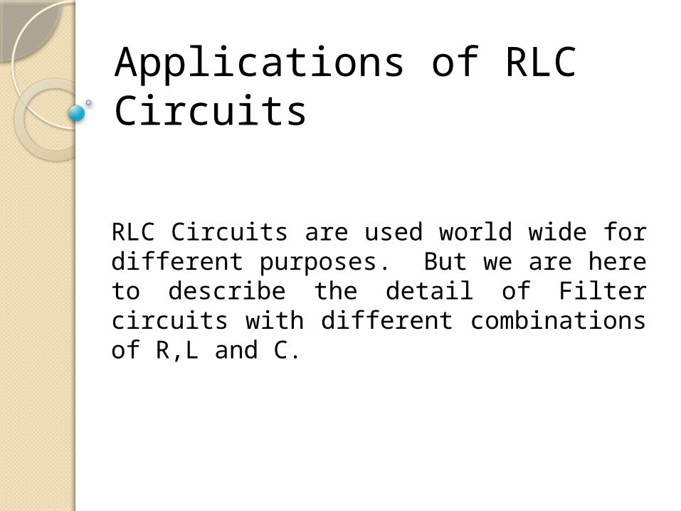
Applications of RLC Circuits
RLC Circuits are used world wide for different purposes. But we are here to describe the detail of Filter circuits with different combinations of R,L and C.
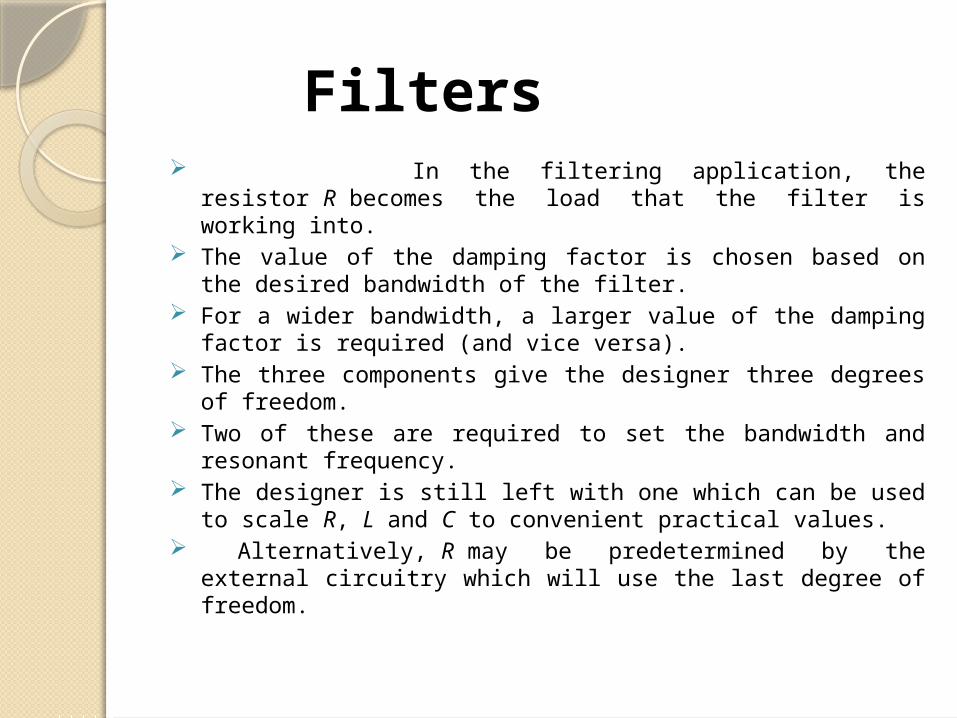
Filters In the filtering application, the resistor R becomes
the load that the filter is working into. The value of the damping factor is chosen based on the
desired bandwidth of the filter. For a wider bandwidth, a larger value of the damping
factor is required (and vice versa). The three components give the designer three degrees
of freedom. Two of these are required to set the bandwidth and
resonant frequency. The designer is still left with one which can be used to
scale R, L and C to convenient practical values. Alternatively, R may be predetermined by the external
circuitry which will use the last degree of freedom.
Types of filters.There are four types of filter as
are following: Low-pass filter
High-pass filter
Band-pass filter
Band-stop filter

Low pass filter A low-pass filter is a circuit offering easy
passage to low-frequency signals and difficult passage to high-frequency signals.
low-pass filter is a filter that passes signals with a frequency lower than a certain cutoff frequency and weak signals with frequencies higher than the cutoff frequency. The amount of weak for each frequency depends on the filter design. The filter is sometimes called a high-cut filter, or treble cut filter in audio applications. A low-pass filter is the opposite of a high-pass filter A band-pass filter is a combination of a low-pass and a high-pass filter.

Low-pass filters exist in many different forms, including electronic circuits (such as a hiss filter used in audio), anti-aliasing filters for conditioning signals prior to analog-to-digital conversion, digital filters for smoothing sets of data, acoustic barriers, blurring of images, and so on. This is also the bandwidth of the filter
RLC circuit as a low-pass filter
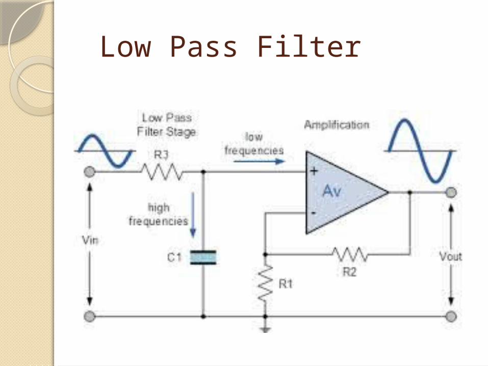
Low Pass Filter

High-pass filterA high pass filter is a filter which passes
high-frequency signals and blocks, or impedes, low-frequency signals.
In other words, high-frequency signals go through much easier and low-frequency signals have a much harder getting through, which is why it's a high pass filter.
RLC circuit as a high-pass filter

The filter has a stop-band of this width. High-pass filters have many
applications. They are used as part of an audio crossover to direct high frequencies to a tweeter while attenuating bass signals which could interfere with, or damage, the speaker. When such a filter is built into a loudspeaker cabinet it is normally a passive filter that also includes a low-pass filter for the woofer and so often employs both a capacitor and inductor (although very simple high-pass filters for tweeters can consist of a series capacitor and nothing else).


Band-pass filter A band-pass filter is a device that
passes frequencies within a certain range and rejects (attenuates) frequencies outside that range. Band pass is an adjective that describes a type of filter or filtering process; it is to be distinguished from pass band, which refers to the actual portion of affected spectrum. Hence, one might say
"A dual band pass filter has two pass bands." A band pass signal is a signal containing a
band of frequencies not adjacent to zero frequency, such as a signal that comes out of a band pass filter.

Caution An ideal band pass filter
would have a completely flat pass band (e.g. with no gain/attenuation throughout) and would completely attenuate all frequencies outside the pass band. Additionally, the transition out of the pass band would have brick wall characteristics.
The bandwidth of the filter is simply the difference between the upper and lower cutoff frequencies. The shape factor is the ratio of bandwidths measured using two different attenuation values to determine the cutoff frequency, e.g., a shape factor of 2:1 at 30/3 dB means the bandwidth measured between frequencies at 30 dB attenuation is twice that measured between frequencies at 3 dB attenuation.
Optical band-pass filters are common in photography and theatre lighting work. These filters take the form of a transparent colored film or sheet.
Q factorA band-pass filter can be
characterized by its Q factor. The Q-factor is the inverse of the fractional bandwidth. A high-Q factor will have a narrow pass band and a low-Q factor will have a wide pass band. These are respectively referred to as narrow-band and wide-band filters.
Applications Band pass filters are widely used in wireless
transmitters and receivers. The main function of such a filter in a transmitter is to limit the bandwidth of the output signal to the band allocated for the transmission. This prevents the transmitter from interfering with other stations. In a receiver, a band pass filter allows signals within a selected range of frequencies to be heard or decoded, while preventing signals at unwanted frequencies from getting through. A band pass filter also optimizes the signal-to-noise ratio and sensitivity of a receiver.
In both transmitting and receiving applications, well-designed band pass filters, having the optimum bandwidth for the mode and speed of communication being used, maximize the number of signal transmitters that can exist in a system, while minimizing the interference or competition among signals.
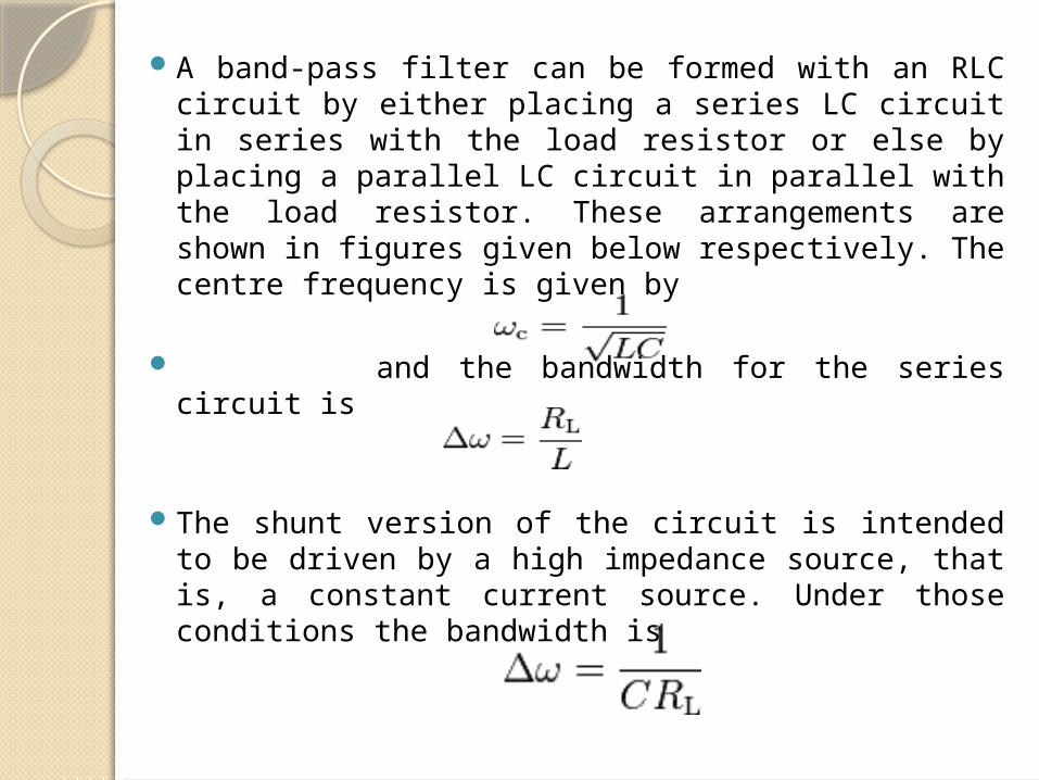
A band-pass filter can be formed with an RLC circuit by either placing a series LC circuit in series with the load resistor or else by placing a parallel LC circuit in parallel with the load resistor. These arrangements are shown in figures given below respectively. The centre frequency is given by
and the bandwidth for the series circuit is The shunt version of the circuit is intended to
be driven by a high impedance source, that is, a constant current source. Under those conditions the bandwidth is

RLC circuit as a series band-pass filter in series with the line
RLC circuit as a parallel band-pass filter in shunt across the line
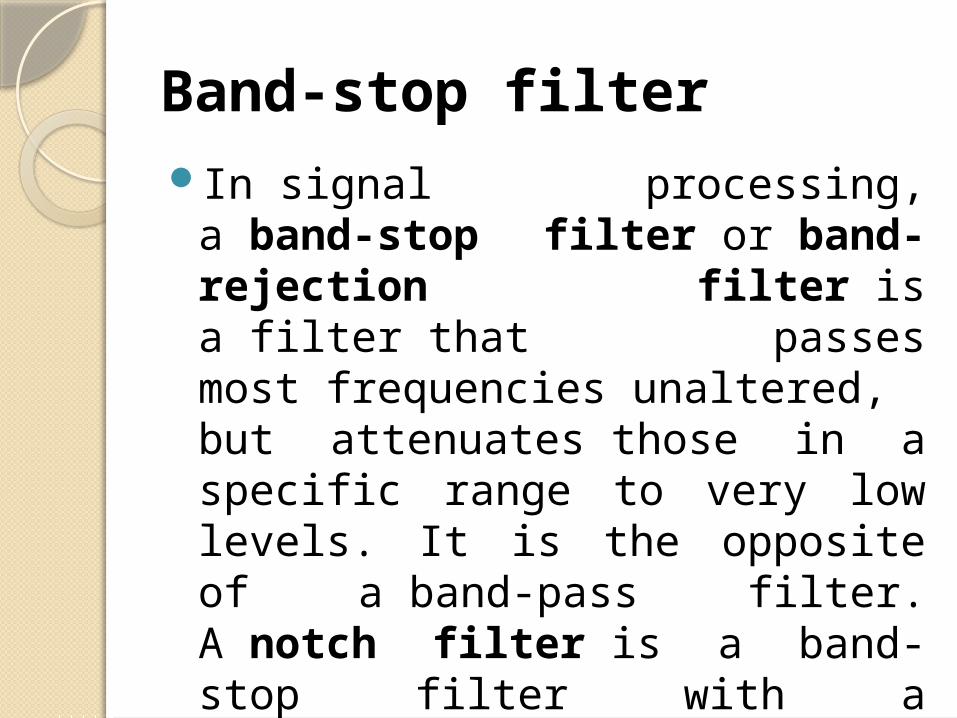
Band-stop filterIn signal processing, a band-
stop filter or band-rejection filter is a filter that passes most frequencies unaltered, but attenuates those in a specific range to very low levels. It is the opposite of a band-pass filter. A notch filter is a band-stop filter with a narrow stop band (high Q factor).

Narrow notch filters (optical) are used in Raman spectroscopy, live sound reproduction (public address systems, or PA systems) and in instrument amplifiers (especially amplifiers or preamplifiers for acoustic instruments such as acoustic guitar, mandolin, bass instrument amplifier, etc.) to reduce or prevent audio feedback, while having little noticeable effect on the rest of the frequency spectrum (electronic or software filters). Other names include 'band limit filter', 'T-notch filter', 'band-elimination filter', and 'band-reject filter'
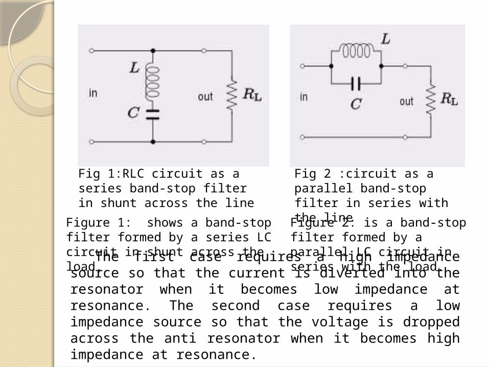
Fig 1:RLC circuit as a series band-stop filter in shunt across the line
Fig 2 :circuit as a parallel band-stop filter in series with the line
Figure 1: shows a band-stop filter formed by a series LC circuit in shunt across the load.
Figure 2: is a band-stop filter formed by a parallel LC circuit in series with the load.The first case requires a high impedance source so that the
current is diverted into the resonator when it becomes low impedance at resonance. The second case requires a low impedance source so that the voltage is dropped across the anti resonator when it becomes high impedance at resonance.

Q&A session Any question regarding my
presentation?
?