Applications Engineering Department Application Note 77 ... · Tel: +1 408 414 9200 Fax: +1 408 414...
28
Power Integrations 5245 Hellyer Avenue, San Jose, CA 95138 USA. Tel: +1 408 414 9200 Fax: +1 408 414 9201 www.power.com Title Getting Started with InnoSwitch TM 3-Pro Code Library using Arduino Author Applications Engineering Department Document Number Application Note 77 (AN-77) Date September 6, 2018 Revision 1.0 Summary InnoSwitch3-Pro is a digitally controllable CV/CC QR Flyback Switcher IC with integrated High Voltage MOSFET, Synchronous Rectification and FluxLink Feedback. RDK-641 is a reference design board rated for 40W output power and is programmable from 3V to 20V output voltage. This reference design features an on board PIC16F18325 microcontroller and uses the InnoSwitch3-Pro integrated power supply IC. This application note describes use of Arduino code libraries provided by Power Integrations to develop control logic and firmware for customizing RDK-641. Information presented in this application note was used to develop firmware for Arduino UNO. PATENT INFORMATION The products and applications illustrated herein (including transformer construction and circuits external to the products) may be covered by one or more U.S. and foreign patents, or potentially by pending U.S. and foreign patent applications assigned to Power Integrations. A complete list of Power Integrations' patents may be found at www.powerint.com. Power Integrations grants its customers a license under certain patent rights as set forth at https://www.power.com/company/intellectual- property-licensing/.
Transcript of Applications Engineering Department Application Note 77 ... · Tel: +1 408 414 9200 Fax: +1 408 414...

Power Integrations 5245 Hellyer Avenue, San Jose, CA 95138 USA.
Tel: +1 408 414 9200 Fax: +1 408 414 9201 www.power.com
Title Getting Started with InnoSwitchTM3-Pro Code Library using Arduino
Author Applications Engineering Department
Document Number
Application Note 77 (AN-77)
Date September 6, 2018
Revision 1.0
Summary
InnoSwitch3-Pro is a digitally controllable CV/CC QR Flyback Switcher IC with integrated High Voltage MOSFET, Synchronous Rectification and FluxLink Feedback.
RDK-641 is a reference design board rated for 40W output power and is programmable from 3V to 20V output voltage. This reference design features an on board PIC16F18325 microcontroller and uses the InnoSwitch3-Pro integrated power supply IC.
This application note describes use of Arduino code libraries provided by Power Integrations to develop control logic and firmware for customizing RDK-641.
Information presented in this application note was used to develop firmware for Arduino UNO.
PATENT INFORMATION The products and applications illustrated herein (including transformer construction and circuits external to the products) may be covered by one or more U.S. and foreign patents, or potentially by pending U.S. and foreign patent applications assigned to Power Integrations. A complete list of Power Integrations' patents may be found at www.powerint.com. Power Integrations grants its customers a license under certain patent rights as set forth at https://www.power.com/company/intellectual-property-licensing/.
AN-77 Getting Started with InnoSwitch3-Pro using Arduino 06-Sep-18
Page 2 of 28
Power Integrations Tel: +1 408 414 9200 Fax: +1 408 414 9201
www.power.com
Table of Contents Introduction ................................................................................................................ 3 1 System Requirements ................................................................................................ 4 2 Hardware Overview .................................................................................................... 5 3
Headers and Jumpers Settings ........................................................................... 5 3.1 InnoSwitch3-Pro Arduino Code Library ...................................................................... 7 4
Library Installation ............................................................................................... 7 4.1 Library Installation Complete ............................................................................... 8 4.2 Library Examples ................................................................................................ 9 4.3
Folder Contents ........................................................................................................ 11 5 File Description ................................................................................................. 12 5.1
Application Example ................................................................................................. 14 6 Step-By-Step Procedure ................................................................................... 14 6.1
Header Files Inclusion ............................................................................... 14 6.1.1 Class Instance Creation ............................................................................. 14 6.1.2
InnoSwitch3-Pro Initialization ..................................................................... 14 6.1.3 Basic Control Functions .............................................................................. 15 6.1.4
Basic Code Examples .................................................................................. 16 6.1.5 Building the Project .................................................................................................. 18 7
Arduino board selection .................................................................................... 18 7.1 Select the Active Com Port ............................................................................... 18 7.2 Verify / Compile ................................................................................................. 19 7.3 Upload ............................................................................................................... 19 7.4
Demonstration of Operation ..................................................................................... 20 8 Running the Program ........................................................................................ 20 8.1 Constant voltage operation ............................................................................... 21 8.2 Constant current operation ................................................................................ 21 8.3
Doxygen Documentation .......................................................................................... 22 9 Opening html file ............................................................................................... 22 9.1 Viewing the API Functions ................................................................................ 23 9.2 Functions summary ........................................................................................... 24 9.3 Functions definition ........................................................................................... 25 9.4 Examples .......................................................................................................... 26 9.5
Revision History .................................................................................................... 27 10
AN-77 Getting Started with InnoSwitch3-Pro using Arduino 06-Sep-18
Page 3 of 28
Power Integrations Tel: +1 408 414 9200 Fax: +1 408 414 9201
www.power.com
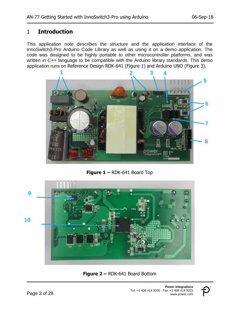
Introduction 1 This application note describes the structure and the application interface of the InnoSwitch3-Pro Arduino Code Library as well as using it on a demo application. The code was designed to be highly portable to other microcontroller platforms, and was written in C++ language to be compatible with the Arduino library standards. This demo
application runs on Reference Design RDK-641 (Figure 1) and Arduino UNO (Figure 3).
Figure 1 – RDK-641 Board Top
Figure 2 – RDK-641 Board Bottom
1 2 3 4
5
6
7
8
9
10

AN-77 Getting Started with InnoSwitch3-Pro using Arduino 06-Sep-18
Page 4 of 28
Power Integrations Tel: +1 408 414 9200 Fax: +1 408 414 9201
www.power.com
The RDK-641 board’s key features are indicated on the table below
Figure 3 – Arduino Uno Rev 3
System Requirements 2 The following are required to run the InnoSwitch3-Pro Arduino demo application
Arduino Software version 1.8.2 or later
Arduino UNO Rev3 SMD
RDK – 641 Board rev C
InnoSwitch3-Pro Arduino Library version 1.0.0
Number Description Label
1 AC Input Terminals TP1, TP2
2 DC Output Terminals TP3, TP4
3 MCU GPIO Headers J8
4 Green LED Indicator D5
5 Pickit3 Programming Header J5
6 Push Buttons SW1, SW2
7 uVCCand I2C Isolation Jumpers J3, J6, J7
8 External Interface Header J4
9 PIC16F18325 microcontroller U3
10 InnoSwitch3-Pro IC U1
SCL SDA GND

AN-77 Getting Started with InnoSwitch3-Pro using Arduino 06-Sep-18
Page 5 of 28
Power Integrations Tel: +1 408 414 9200 Fax: +1 408 414 9201
www.power.com
Hardware Overview 3
The Reference Design (RDK-641) hardware consists of an 8-bit Microchip microcontroller (PIC16F18325), interface headers and the user interface elements: two push buttons and a green LED. The InnoSwitch3-Pro can be controlled using it’s on board microcontroller or by an external I2C Master through the interface header. This Demo Application does not use the on board microcontroller but an Arduino Uno as an I2C Master and InnoSwitch3-Pro as slave device.
SDA and SCL lines pull-up resistors R24 and R23 respectively are available on the board. The output of the InnoSwitch3-Pro provides 3.6V pull up voltage from its μVCC output pin.
To further ease in development, the following documents are available and recommended as supplemental reference resources I2C
RDR-641 - 40 W Variable Output (3 V to 8 V, 5 A; 8 V – 20 V Constant Power)
Supply Using InnoSwitch3-Pro and Microchip’s PIC16F18325 Microcontroller
AN-74 InnoSwitch3-Pro Programming Manual
Headers and Jumpers Settings 3.1
The table provides the description for each jumper available on the board.
Jumper Description Settings
J3 uVCC and MCU Supply Jumper
If connected the uVCC output pin of the InnoSwitch3-Pro will provide power to the on board microcontroller and
provide pull up voltage to the I2C lines
J6 , J7 I2C Lines Isolation Jumper
The user can select whether or not the SDA and SCL lines from the MCU will be connected to the InnoSwitch3-Pro
The following headers are also available on the board.
Header Description Settings
J4 InnoSwitch3-Pro I2C lines
Header When J6 and J7 are removed, an external I2C
Master can be connected through these header
J5 PICkit3 Programming
Header For MCU Firmware Update using PICkit3 In-
Circuit Debugger/Programmer
J8 MCU GPIO Header This can be used as Debug Pins
AN-77 Getting Started with InnoSwitch3-Pro using Arduino 06-Sep-18
Page 6 of 28
Power Integrations Tel: +1 408 414 9200 Fax: +1 408 414 9201
www.power.com
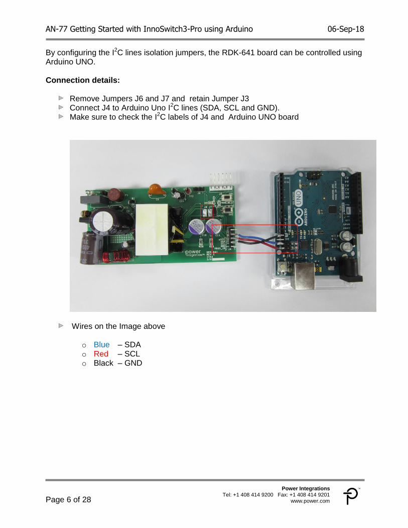
By configuring the I2C lines isolation jumpers, the RDK-641 board can be controlled using Arduino UNO. Connection details:
Remove Jumpers J6 and J7 and retain Jumper J3 Connect J4 to Arduino Uno I2C lines (SDA, SCL and GND). Make sure to check the I2C labels of J4 and Arduino UNO board
Wires on the Image above
o Blue – SDA o Red – SCL o Black – GND
AN-77 Getting Started with InnoSwitch3-Pro using Arduino 06-Sep-18
Page 7 of 28
Power Integrations Tel: +1 408 414 9200 Fax: +1 408 414 9201
www.power.com
InnoSwitch3-Pro Arduino Code Library 4
To simplify the technicalities on controlling the InnoSwitch3-Pro, a simple code library is provided as a reference. The library contains all the registers needed for controlling the device. These registers are organized as Command Registers and Telemetry registers. Command registers are sent to the device for performance control and Telemetry Registers are for reading back values. Computation Macros are presented to aid in set point calculations. Register default values are also defined to simplify writing to the required registers at device initialization. The InnoSwitch3-Pro Arduino code library is available from the Power integrations website.
https://ac-dc.power.com/design-support/articles/innoswitch3-pro-code-library-api-arduino/
Library Installation 4.1
Full installation guide can be found on the link below https://www.arduino.cc/en/Guide/Libraries
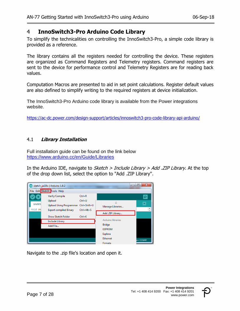
In the Arduino IDE, navigate to Sketch > Include Library > Add .ZIP Library. At the top of the drop down list, select the option to "Add .ZIP Library''.
Navigate to the .zip file's location and open it.
AN-77 Getting Started with InnoSwitch3-Pro using Arduino 06-Sep-18
Page 8 of 28
Power Integrations Tel: +1 408 414 9200 Fax: +1 408 414 9201
www.power.com
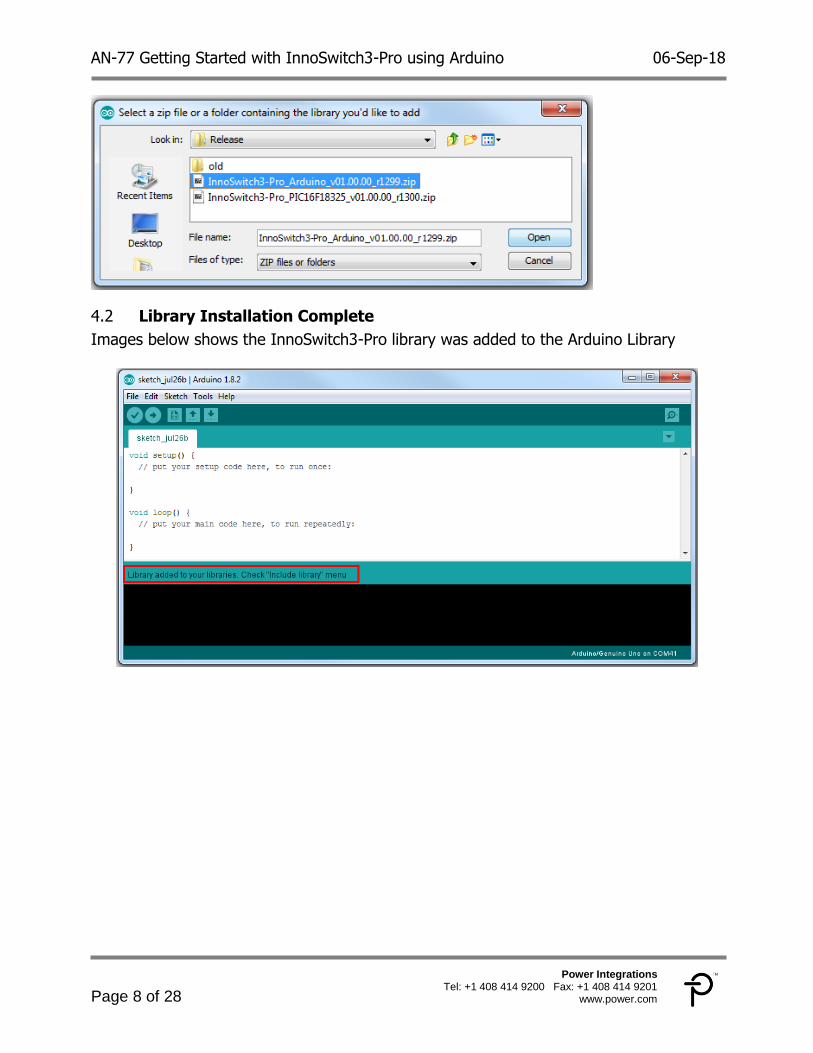
Library Installation Complete 4.2
Images below shows the InnoSwitch3-Pro library was added to the Arduino Library
AN-77 Getting Started with InnoSwitch3-Pro using Arduino 06-Sep-18
Page 9 of 28
Power Integrations Tel: +1 408 414 9200 Fax: +1 408 414 9201
www.power.com
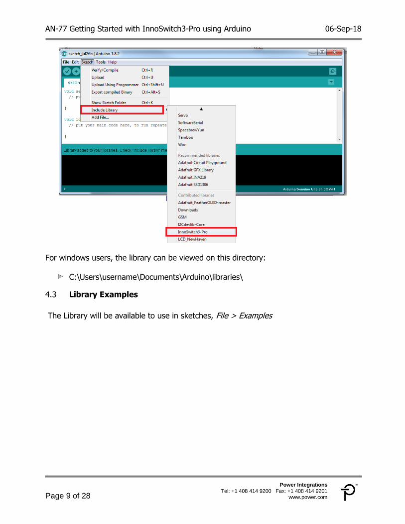
For windows users, the library can be viewed on this directory:
C:\Users\username\Documents\Arduino\libraries\
Library Examples 4.3
The Library will be available to use in sketches, File > Examples

AN-77 Getting Started with InnoSwitch3-Pro using Arduino 06-Sep-18
Page 10 of 28
Power Integrations Tel: +1 408 414 9200 Fax: +1 408 414 9201
www.power.com
AN-77 Getting Started with InnoSwitch3-Pro using Arduino 06-Sep-18
Page 11 of 28
Power Integrations Tel: +1 408 414 9200 Fax: +1 408 414 9201
www.power.com
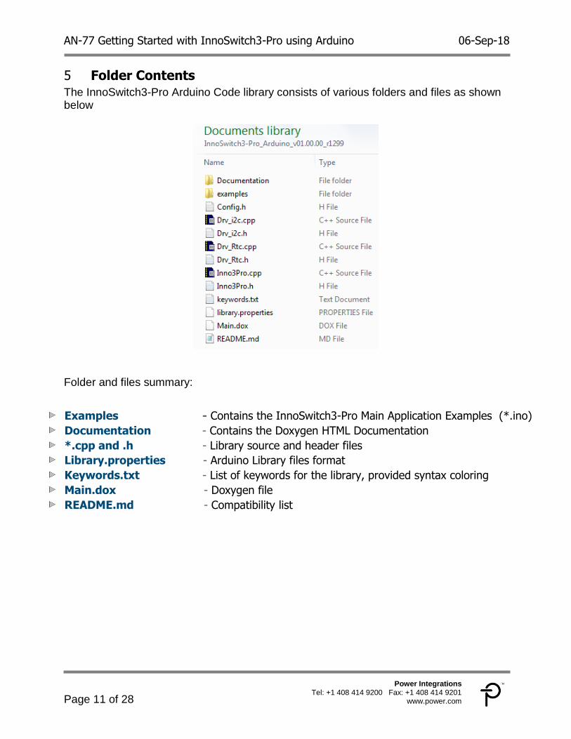
Folder Contents 5The InnoSwitch3-Pro Arduino Code library consists of various folders and files as shown below
Folder and files summary:
Examples - Contains the InnoSwitch3-Pro Main Application Examples (*.ino)
Documentation - Contains the Doxygen HTML Documentation
*.cpp and .h - Library source and header files
Library.properties - Arduino Library files format
Keywords.txt - List of keywords for the library, provided syntax coloring
Main.dox - Doxygen file
README.md - Compatibility list
AN-77 Getting Started with InnoSwitch3-Pro using Arduino 06-Sep-18
Page 12 of 28
Power Integrations Tel: +1 408 414 9200 Fax: +1 408 414 9201
www.power.com
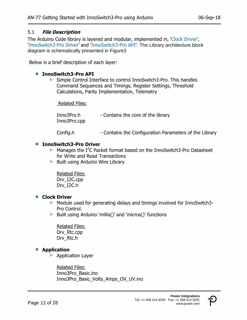
File Description 5.1
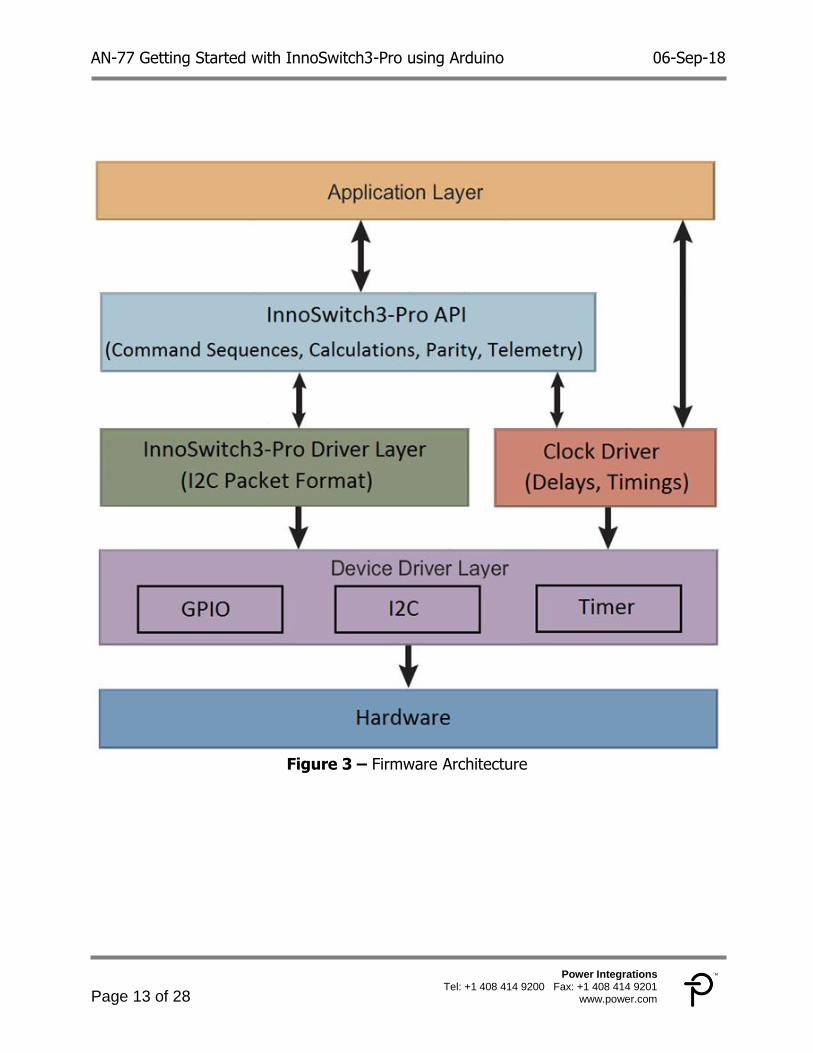
The Arduino Code library is layered and modular, implemented in, ‘Clock Driver’, ‘InnoSwitch3-Pro Driver’ and ‘InnoSwitch3-Pro API’. The Library architecture block diagram is schematically presented in Figure3
Below is a brief description of each layer:
InnoSwitch3-Pro API Simple Control Interface to control InnoSwitch3-Pro. This handles
Command Sequences and Timings, Register Settings, Threshold Calculations, Parity Implementation, Telemetry
Related Files: Inno3Pro.h - Contains the core of the library Inno3Pro.cpp Config.h - Contains the Configuration Parameters of the Library
InnoSwitch3-Pro Driver Manages the I2C Packet format based on the InnoSwitch3-Pro Datasheet
for Write and Read Transactions Built using Arduino Wire Library
Related Files: Drv_I2C.cpp Drv_I2C.h
Clock Driver Module used for generating delays and timings involved for InnoSwitch3-
Pro Control. Built using Arduino ‘millis()’ and ‘micros()’ functions
Related Files: Drv_Rtc.cpp Drv_Rtc.h
Application Application Layer
Related Files: Inno3Pro_Basic.ino Inno3Pro_Basic_Volts_Amps_OV_UV.ino
AN-77 Getting Started with InnoSwitch3-Pro using Arduino 06-Sep-18
Page 13 of 28
Power Integrations Tel: +1 408 414 9200 Fax: +1 408 414 9201
www.power.com
Figure 3 – Firmware Architecture

AN-77 Getting Started with InnoSwitch3-Pro using Arduino 06-Sep-18
Page 14 of 28
Power Integrations Tel: +1 408 414 9200 Fax: +1 408 414 9201
www.power.com
Application Example 6
This section describes the step-by-step procedures for setting up the Arduino sketch for InnoSwitch3-Pro.
Step-By-Step Procedure 6.1
Header Files Inclusion 6.1.1
The library header files contain all of the function declarations and macro definitions. This must be included in the main page as shown.
Class Instance Creation 6.1.2
Construct a Class instance to call the functions inside Inno3Pro_Application. Constructing a Class instance of Inno3Pro_Rtc is Optional.
InnoSwitch3-Pro Initialization 6.1.3
Before continuous execution of the main code, the status of System Ready Signal is monitored to ensure the InnoSwitch3-Pro is ready to receive I2C commands. Afterwards initialization commands are sent to the device to configure the default settings. This initialization routine disables the watchdog timer and Fast VI Limit. UVL timer is also initialized to 64ms. The 400 kHz clock frequency for I2C communication is set-up on initialization.

AN-77 Getting Started with InnoSwitch3-Pro using Arduino 06-Sep-18
Page 15 of 28
Power Integrations Tel: +1 408 414 9200 Fax: +1 408 414 9201
www.power.com
Basic Control Functions 6.1.4
Updates the Output Voltage and Constant Current Setting
Follows a certain sequence of I2C commands in order to avoid inadvertent triggering of UV or OV faults
Controls the VOUT pin strong bleeder when Decreasing the voltage from High to Low Setting
Automatically updates the Over Voltage (OVA) and Under Voltage (UVA) settings OVA is 124% of CV Setpoint UVA is Fixed to 3V Setting
Inno3Pro.Inno3Pro_Write_VI( Volts, Amps )
Updates the Output Voltage without Bleeder Control
Inno3Pro.Inno3Pro_Write_Volts( Volts )
Sets the Constant Current Setting
Inno3Pro.Inno3Pro_Write_Amps( Amps )
Sets the Over Voltage Setting
Inno3Pro.Inno3Pro_Write_Over_Volts( Value )
Sets the Under Voltage Setting
Inno3Pro.Inno3Pro_Write_Under_Volts( Value )
Sets the Cable Drop Compensation Value
Inno3Pro.Inno3Pro_Write_Cable_Drop_Comp( Value )
Sets the Constant Output Power Threshold
Inno3Pro.Inno3Pro_Write_Volt_Peak( Value )
Used for Turning On or Off the Bus Voltage Switch
Inno3Pro.Inno3Pro_Vbus_Switch_Control( Value )
Used for Turning On or Off the VOUT pin strong bleeder
The BLEEDER must not be enabled for extended period of time to prevent excessive power dissipation in the controller
Inno3Pro.Inno3Pro_Bleeder_Enable ( Value )

AN-77 Getting Started with InnoSwitch3-Pro using Arduino 06-Sep-18
Page 16 of 28
Power Integrations Tel: +1 408 414 9200 Fax: +1 408 414 9201
www.power.com
Basic Code Examples 6.1.5
Example 1 - Inno3Pro_Basic.ino 6.1.5.1
Demonstrates the basic usage of InnoSwitch3-Pro Arduino Library.
Initial commands are sent using the InnoSwitch3-Pro Initialization Routine. The Main Routine using write VI sets the output voltage to 5V and constant current
current to 5.1A. Cable Drop Compensation is programmed to 300mV. Constant power is knee voltage is set to 7V and then Vbus Switch is turned ON
This code example is presented on “examples\Inno3Pro_Basic\Inno3Pro_Basic.c” Copy and paste these contents to your Arduino sketch.
AN-77 Getting Started with InnoSwitch3-Pro using Arduino 06-Sep-18
Page 17 of 28
Power Integrations Tel: +1 408 414 9200 Fax: +1 408 414 9201
www.power.com
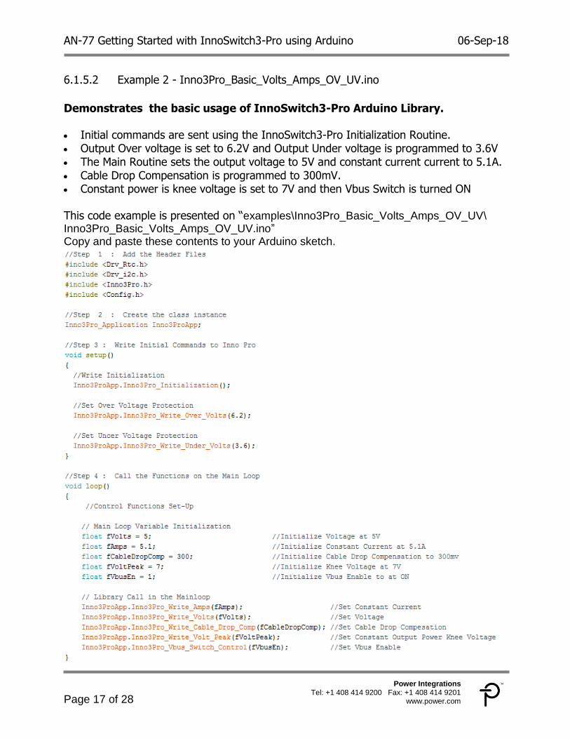
Example 2 - Inno3Pro_Basic_Volts_Amps_OV_UV.ino 6.1.5.2
Demonstrates the basic usage of InnoSwitch3-Pro Arduino Library.
Initial commands are sent using the InnoSwitch3-Pro Initialization Routine. Output Over voltage is set to 6.2V and Output Under voltage is programmed to 3.6V The Main Routine sets the output voltage to 5V and constant current current to 5.1A. Cable Drop Compensation is programmed to 300mV. Constant power is knee voltage is set to 7V and then Vbus Switch is turned ON
This code example is presented on “examples\Inno3Pro_Basic_Volts_Amps_OV_UV\ Inno3Pro_Basic_Volts_Amps_OV_UV.ino” Copy and paste these contents to your Arduino sketch.

AN-77 Getting Started with InnoSwitch3-Pro using Arduino 06-Sep-18
Page 18 of 28
Power Integrations Tel: +1 408 414 9200 Fax: +1 408 414 9201
www.power.com
Building the Project 7
Arduino board selection 7.1
Under tools menu, Select Arduino UNO board Make sure your Arduino Uno is already connected to your computer
through the usb port
Select the Active Com Port 7.2
Under tools menu, Select the correct port For Arduino UNO, the name will appear next to the serial port

AN-77 Getting Started with InnoSwitch3-Pro using Arduino 06-Sep-18
Page 19 of 28
Power Integrations Tel: +1 408 414 9200 Fax: +1 408 414 9201
www.power.com
Verify / Compile 7.3
Click the check icon to Verify After few seconds , “Done Compiling” should show up on the Notification Area
This means the sketch is ready for uploading to the Arduino board
Upload 7.4
Click the Arrow icon to Upload After few seconds , “Done Uploading” should show up on the Notification Area
This means the upload was successful
AN-77 Getting Started with InnoSwitch3-Pro using Arduino 06-Sep-18
Page 20 of 28
Power Integrations Tel: +1 408 414 9200 Fax: +1 408 414 9201
www.power.com
Demonstration of Operation 8
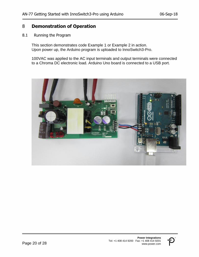
Running the Program 8.1
This section demonstrates code Example 1 or Example 2 in action. Upon power up, the Arduino program is uploaded to InnoSwitch3-Pro. 100VAC was applied to the AC input terminals and output terminals were connected to a Chroma DC electronic load. Arduino Uno board is connected to a USB port.

AN-77 Getting Started with InnoSwitch3-Pro using Arduino 06-Sep-18
Page 21 of 28
Power Integrations Tel: +1 408 414 9200 Fax: +1 408 414 9201
www.power.com
Constant voltage operation 8.2
Image below shows the operation of RDK-641 at constant voltage of 5V and Full load of 5.1A
Constant current operation 8.3
Image below shows the operation of RDK-641 at constant current mode
AN-77 Getting Started with InnoSwitch3-Pro using Arduino 06-Sep-18
Page 22 of 28
Power Integrations Tel: +1 408 414 9200 Fax: +1 408 414 9201
www.power.com
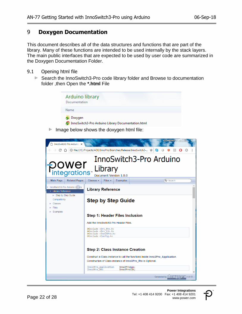
Doxygen Documentation 9 This document describes all of the data structures and functions that are part of the library. Many of these functions are intended to be used internally by the stack layers. The main public interfaces that are expected to be used by user code are summarized in the Doxygen Documentation Folder.
Opening html file 9.1
Search the InnoSwitch3-Pro code library folder and Browse to documentation folder ,then Open the *.html File
Image below shows the doxygen html file:

AN-77 Getting Started with InnoSwitch3-Pro using Arduino 06-Sep-18
Page 23 of 28
Power Integrations Tel: +1 408 414 9200 Fax: +1 408 414 9201
www.power.com
Viewing the API Functions 9.2
Under Inno3_Application Class List, Select and Open Function Summary and Description:
AN-77 Getting Started with InnoSwitch3-Pro using Arduino 06-Sep-18
Page 24 of 28
Power Integrations Tel: +1 408 414 9200 Fax: +1 408 414 9201
www.power.com
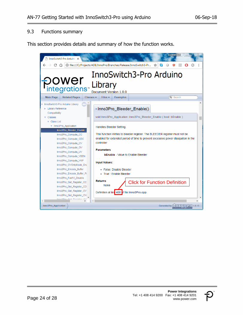
Functions summary 9.3
This section provides details and summary of how the function works.
Click for Function Definition

AN-77 Getting Started with InnoSwitch3-Pro using Arduino 06-Sep-18
Page 25 of 28
Power Integrations Tel: +1 408 414 9200 Fax: +1 408 414 9201
www.power.com
Functions definition 9.4
This section provides the actual body and implementation of the function

AN-77 Getting Started with InnoSwitch3-Pro using Arduino 06-Sep-18
Page 26 of 28
Power Integrations Tel: +1 408 414 9200 Fax: +1 408 414 9201
www.power.com
Examples 9.5
This section provides different examples that showcase the use of the library functions
AN-77 Getting Started with InnoSwitch3-Pro using Arduino 06-Sep-18
Page 27 of 28
Power Integrations Tel: +1 408 414 9200 Fax: +1 408 414 9201
www.power.com
Revision History 10
Date Author Revision Description & changes Reviewed
06-Sep-18 CS 1.0 Initial Release Apps and Mktg
AN-77 Getting Started with InnoSwitch3-Pro using Arduino 06-Sep-18
Page 28 of 28
Power Integrations Tel: +1 408 414 9200 Fax: +1 408 414 9201
www.power.com