Application of Impact-echo Method to Degradation Diagnosis ...
13
沿岸域学会誌/第23巻 第2号 2010.12 1. Introduction Fishing port, a major coastal structure in fishing village area, is approx. 3000 in number located in Japan forming a huge existing stocks. Construction of fishing port facilities started at the high-growth period and the fishing port fa- cilities more than 30-year old dominates almost 40 percent. They are now subjected to updating with a fear of considerable deterioration (Fig. 1). Within the limited budget, the central and local governments should proceed appropriate main- tenance including timely repair and rehabilitation for the existing stocks. In this circumstance, the Life Cycle Management (hereafter referred to as LCM) capable of optimizing the entire cost of repair, retrofitting and rehabilitation of the facili- ties in their service lives attracts attentions. Basic concept of LCM for the fishing port facili- ties was outlined 1) as shown in Fig. 2 while it is still under development leaving a number of tasks including selection of deterioration diagno- sis method, advancement of accuracy in the di- agnosis, simplification of inspection and diagno- sis procedure, and advancement of precision in * Member Fisheries Infrastructure Department, Fisheries Agency, ** Non-Member Department of Civil Engineering, Tokai University Fig. 1 State of deterioration of concrete at fishing port. Application of Impact-echo Method to Degradation Diagnosis of Existing Coastal Structures Nobuo MIKAMI* and Tetsuro KASAI** ABSTRACT:Fishing port facilities are the main coastal structure in fishing village and form a large number of existing stocks for which introduction of life-cycle management such as durability upgrading and life ex- tension measures is needed. To this end, degradation level of the facilities must be known and the degradation diagnosis must take into account the particularity of each facility. Hence, the scatter in diagnosis results by operator and inefficiency of diagnosis procedure should be eliminated by clear evaluation criteria and labor saving diagnosis procedure. This study aims at establishing a degradation index and simplification of diagno- sis procedure applicable to the fishing port facilities. Applicability of impact-echo method using surface P-wave to the degradation diagnosis of fishing port facilities was investigated for the first time in terms of effects of moisture content and expansive cracks of concrete. Finally, accuracy and applicable range of the diagnosis method were studied using existing fishing port facilities. KEYWORDS : Fishing Port Facility, Concrete Structure, LCM, Degradation Diagnosis, Impact-echo Method 沿岸域学会誌, Vol.23 No.2,pp. 85-97 (Journal of Coastal Zone Studies) 報告 2010 年 12 月 -85-
Transcript of Application of Impact-echo Method to Degradation Diagnosis ...

沿岸域学会誌/第23巻 第2号 2010.12
1. Introduction
Fishing port, a major coastal structure in
fishing village area, is approx. 3000 in number
located in Japan forming a huge existing stocks.
Construction of fishing port facilities started at
the high-growth period and the fishing port fa-
cilities more than 30-year old dominates almost
40 percent. They are now subjected to updating
with a fear of considerable deterioration (Fig. 1).
Within the limited budget, the central and local
governments should proceed appropriate main-
tenance including timely repair and rehabilitation
for the existing stocks. In this circumstance, the
Life Cycle Management (hereafter referred to as
LCM) capable of optimizing the entire cost of
repair, retrofitting and rehabilitation of the facili-
ties in their service lives attracts attentions.
Basic concept of LCM for the fishing port facili-
ties was outlined1)
as shown in Fig. 2 while it is
still under development leaving a number of
tasks including selection of deterioration diagno-
sis method, advancement of accuracy in the di-
agnosis, simplification of inspection and diagno-
sis procedure, and advancement of precision in
* Member Fisheries Infrastructure Department, Fisheries Agency,
** Non-Member Department of Civil Engineering, Tokai University
Fig. 1 State of deterioration of concrete at fishing
port.
Application of Impact-echo Method to Degradation Diagnosis
of Existing Coastal Structures
Nobuo MIKAMI* and Tetsuro KASAI**
ABSTRACT:Fishing port facilities are the main coastal structure in fishing village and form a large number
of existing stocks for which introduction of life-cycle management such as durability upgrading and life ex-
tension measures is needed. To this end, degradation level of the facilities must be known and the degradation
diagnosis must take into account the particularity of each facility. Hence, the scatter in diagnosis results by
operator and inefficiency of diagnosis procedure should be eliminated by clear evaluation criteria and labor
saving diagnosis procedure. This study aims at establishing a degradation index and simplification of diagno-
sis procedure applicable to the fishing port facilities. Applicability of impact-echo method using surface
P-wave to the degradation diagnosis of fishing port facilities was investigated for the first time in terms of
effects of moisture content and expansive cracks of concrete. Finally, accuracy and applicable range of the
diagnosis method were studied using existing fishing port facilities.
KEYWORDS:Fishing Port Facility, Concrete Structure, LCM, Degradation Diagnosis, Impact-echo Method
沿岸域学会誌, Vol.23 No.2,pp. 85-97 (Journal of Coastal Zone Studies)
報告
2010 年 12 月
-85-

三上・笠井:
沿岸域学会誌/第23巻 第2号 2010.12
LCC estimation result. It was particularly pointed
out that human factors such as operators’ knowl-
edge and skill and the geographical conditions of
the facilities (immersion or hiding by
wave-absorbing constructions) pose significant
impact on the accuracy in diagnosis.
Taking into account the problems with main-
tenance of fishing port facilities, this study fo-
cused on the impact-echo method among other
non-destructive, inexpensive and easy-operation
methods applicable to large-scale concrete struc-
tures. Laboratory test was conducted to study the
characteristics and applicability of the im-
pact-echo method to fishing ports, which was
then evaluated in the field test at existing fishing
ports to examine the new application.
2. Degradation diagnosis method applica-
ble to fishing port facilities
2.1 Characteristics of degradation in the fish-
ing port facilities
Fishing port facilities comprising huge
amount of existing stocks show following char-
acteristics.
(a) Shapes of concrete structures are generally
elongated as typically seen in a breakwater.
(b) Because they are close to the coastal zone,
chemical or physical degradation is easy to occur
at concrete surfaces due to waves and seawater.
(c) Major facilities are made of reinforced con-
crete and sometimes of plain concrete in revet-
ment facilities. (Almost 50 percent of the total
length)
(d) Quay walls are normally backfilled as shown
in Fig. 3 hence the approach to the facility for
degradation diagnosis is limited, from the top or
horizontally from the sea side.
2.2 Target of degradation diagnosis of the
fishing port facilities
Fishing port facilities have been built as new
or extension constructions without taking main-
tenance strategy into account and appropriate
degradation diagnosis have never been attempted
as yet. Managers of the fishing port facilities are
aware of the necessity of diagnosis for the facili-
ties dotted along the littoral regions, while they
have no objective procedure and definite means
for the necessary diagnosis in addition to the li-
mitation in budget and management system. To
manage this limitation, the following LCM must
Fig. 2 Approximate LCM flow for fishing port
facilities.
H.W.L.
L.W.L.
Fig. 3 Quaywall cross section .
Setting the goal of maintenance
Checkup (routine, regular and extra)
Inspecting the current situation of facilities
Soundness evaluation of facilities
(decision and prediction of degradation level)
Formulation (or review) of maintenance strategy
(determination of countermeasure construction method,
LCC optimization)
Execution of repair, reinforcing and improvement
Monitoring
-86-
既設沿岸コンクリート構造物の劣化診断への衝撃弾性波法の適用
沿岸域学会誌/第23巻 第2号 2010.12
be introduced for the efficient and appropriate
maintenance of the existing facilities.
(a) Selection of optimum repair construction
method and smoothing the budget for the main-
tenance and update of the existing facilities.
(b) Development of efficient degradation diagno-
sis according to the step-by-step procedure as
shown in Fig. 4 to accelerate the diagnosis of
entire existing facilities
(c) Development of quantitative and easy diag-
nosis method applicable to elongated members to
ensure universal and objective evaluation method
for the soundness of structure.
However, considerable time and budget are
needed to execute consecutive degradation diag-
nosis over the existing stocks, and any simple
methods using visual observation and simple
equipment may lead to a considerable scatter in
the diagnosis results depending on the operators’
skill and geographical conditions of the structure.
In addition, detailed inspection requires high ex-
pertise and expensive inspection const. Hence, as
stated in the previous section (c), development of
an exact, reliable and accurate diagnosis method
for the simple inspection is an ideal measure to
execute rapid and efficient degradation diagnosis
and to save labor, inspection cost and finally
LCC.
3. Degradation diagnosis using im-
pact-echo method
3.1 The impact-echo method
Non-destructive testing method is widely ap-
plied to on-site degradation diagnosis2) 3)
and
various equipment and analytical methods are
under developing because it does not harm
structures and relatively easy to figure out the
degradation state.
Among non-destructive testing methods, the
impact-echo method shows following advan-
tages; it is relatively easy to use, rapid in meas-
urement and inexpensive. Energy input by impact
is large enough to cover a wide area of meas-
urement. Effect of reinforcing steel and aggregate
is small owing to the use of long-wavelength
elastic wave. A variety of testing is possible in-
cluding estimation of concrete compressive
strength, internal flaw detection and crack depth
measurement. It is thus very likely that the im-
pact-echo method could be applied to the degra-
dation diagnosis of fishing port facilities, which
are mainly composed of reinforced concrete.
Impact-echo method can detect size and posi-
tion of cracks and internal flaws in concrete us-
ing elastic wave that is generated by impact
transmitter and received with a receiver both
placed on the concrete surface. The applicable
range depends on the frequency of the elastic
wave and the transmission distance becomes
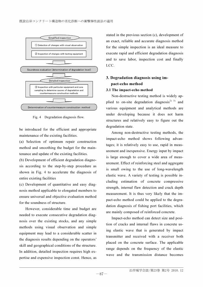
① Detection of changes with visual observation
② Inspection of changes with testing equipment
Simplified inspection
③ Inspection with particular equipment and core
sampling to determine causes of degradation and
countermeasure construction methods
Detailed inspection
Soundness evaluation (determination of degradation level)
Determination of countermeasure construction method
Fig. 4 Degradation diagnosis flow.
-87-

三上・笠井:
沿岸域学会誌/第23巻 第2号 2010.12
longer at lower frequencies4)
.
3.2 Characteristics of the impact-echo method
Some standard impact-echo methods for di-
agnosis of structures are known in overseas
countries5)
while no standard is available in our
country. However, estimation methods of
strength6)
, thickness and internal flaws7,8)
of con-
crete members has been proposed by the Ministry
of Land, Infrastructure, Transport and Tourism.
Impact-echo method uses an elastic wave that
is generated by a steel ball or impact hammer and
received with a receiver placed on the surface of
a concrete member. Elastic wave comprises
compressive wave (P-wave) vibrating parallel to
the traveling direction, shear wave (S-wave) vi-
brating perpendicular to the traveling direction
and Rayleigh wave (R-wave) propagating along
the surface as shown in Fig. 5. When a receiver
of the elastic wave is placed on the concrete sur-
face, waveforms of P-wave, S-wave and R-wave
at the receiver can be given as schematically
shown in Fig. 6 where P-wave reaches first9)
.
Hence detection of the arrival time of the first
elastic wave and the distance between the impact
point and the receiver could give a P-wave speed
that travels at the surface (hereafter called as
surface P-wave) as shown in Fig. 7. Carino10)
compiled diagnosis methods using surface
P-wave, and the strength estimation method pro-
posed by the Ministry of Land, Infrastructure,
Transport and Tourism uses surface P-wave
speed.
3.3 Application of the impact-echo method to
the fishing port facilities
A more accurate degradation estimation be-
comes possible when the impact-echo method
with a large transmission length is introduced and
an objective degradation criteria (degradation
index) is established taking into account the
characteristics of existing fishing port facilities
as stated in 2.1. Regular monitoring of degrada-
P
S
RRDirect PDirect P
Impact
Fig. 5 Elastic waves generated by the impact on
the surface of concrete member. 9)
Displacements caused by
Internal reflectionsP S
R
Time
Fig. 6 Schematic representation of P, S and R-waves
at arrival. 10)
[ Input wave form ]
[ Received wave form ]
t=0.24738msec
[ Propagation time ]
0.0194 0.0294 0.0394 0.0494 0.0594 0.0694 0.0794 0.0894
Time(ms)
mv/(m/s2)
mv/(m/s2)
1000
1000-1000
-1000
~ ~
~ ~
Fig. 7 An example of impact-induced wave forms.
-88-

既設沿岸コンクリート構造物の劣化診断への衝撃弾性波法の適用
沿岸域学会誌/第23巻 第2号 2010.12
tion of structures based on the quantitative deg-
radation criteria using impact-echo method may
contribute to the early detection of degradation of
the huge existing fishing port facilities.
In this study, the degradation diagnosis me-
thod using surface P-wave, which has a large
transmission length and can be favorably appli-
cable to concrete structures among other
non-destructive testing methods, is introduced to
the simplified inspection as described in Fig. 4
②. However, the existing studies of the applica-
tion of the impact-echo method dealt mainly with
new structures built on the land7), 11), 12)
, and those
with old and coastal structures are quite few. It is
a novel approach of this study that the degrada-
tion diagnosis using surface P-wave method was
applied to the existing coastal structures having
largely different degradation characteristics and
structural systems from the land-based structures.
On-site tests for the 30 to 40 year-old existing
fishing port facilities as well as laboratory tests
with various types of concrete specimens were
conducted to figure out the transmission charac-
teristics of the surface P-wave method. Because
of its simplicity and perspicuity, the method us-
ing surface P-wave speed was adopted, and the
applicability of the impact-echo method to the
fishing ports was examined in terms of identifi-
cation of “deterioration positions in concrete
structure” and “evaluation of relative deteriora-
tion condition.” Particular care was paid for the
surface P-wave transmission characteristics at a
transmission length of few meters.
4. Laboratory tests
Before applying to the fishing port facilities
located closed to the coast, performance of the
impact-echo test system and reproducibility of
the past research results were examined in the
laboratory. Especially, the effects of seawater
were concerned in application, hence the effects
of surface deterioration and expansive cracks due
to corrosion and frost damage on the surface
P-wave transmission were studied.
4.1 Testing methods
(1) Effects of compressive strength
Effects of compressive strength were exam-
ined in the test series 1 and 2 and the materials
used and mix proportions are shown in Tables 1
and 2. Water-cement ratio was 0.35, 0.5 and 0.65
to have three compressive strength levels.
Specimens for the surface P-wave speed
measurement were produced using a metal form
with a size of 150 x 150 x 900 mm. Specimens
were unmolded 24 hours after placing and
subjected to under water curing of 20±1°C for 27
Table 1 Materials used.
Material Type Nota-
tionProperties or ingredients
Cement Ordinary port-
land cement C Density: 3.16 g/cc
Fine
aggregate
Ooigawa
crushed sand S
Density: 2.59 g/cc
F.M: 3.00.
Coarse
aggregate
Fujigawa
crushed rock G
Density: 2.70 g/cc
Max. size: 20mm.
AE water re-
ducing agent AE
Lignin sulfonic acid and
polyol compound
Super plasti-
cizer SP Polycarboxylic acid type Admixture
Lime type ex-
pansion agent E
Density: 3.16 g/cc
Std. substitution: 20 kg/m3.
Table 2 Mix proportions.
Unit content (kg/m3) Admixture
(kg/m3)
P Series No. W/C
W C E
S G AE SP
1 0.35 162 463 - 717 998 - 3.01
2 0.50 162 324 - 819 1010 0.97 - 1
3 0.65 172 264 -- 866 986 0.66 -
4 324 0 -
5 304 20 -
6 274 50
0.97
- 2
7
0.50 162
244 80
819 1010
1.62 -
-89-

三上・笠井:
沿岸域学会誌/第23巻 第2号 2010.12
under water curing of 20±1°C for 27 days. Con-
cept of the laboratory test for surface P-wave
speed is shown in Fig 8. Accelerometers working
as a receiver (Manufactured by company P with a
sampling frequency of 0.5 µs) were glued to en-
sure the contact with the concrete surface at any
positions. Impact source was an impact hammer
with an impact accelerometer working as a
transmitter which introduced an impact at every
100 mm spacing within 800 mm distance from
the receiver13)
. Traveling times at each distance
were recorded and subjected to the least-square
regression analysis. Surface P-wave speed was
obtained as the gradient of the regression line.
The age of the concrete specimen was 28 days.
(2) Effects of moisture content
Specimens were the same as used in the test of
the effect of compressive strength and hence had
three compressive strength levels. At the age of
28 days, specimens were cured in air until the
age of 160 days and, after the measurement of
dry mass and surface P-wave speed, immersed in
water for 7 days. Wet mass and surface P-wave
speed was measured immediately and after air
drying of 1, 2, 14, 42 and 45 days. After 42-day,
specimens were subjected to oven drying at
105 °C for 3 days. Measuring method of surface
P-wave speed was the same as used in section (1),
and changes in moisture content of concrete were
calculated based on the mass loss of specimen.
(3) Effects of swelling and expansive cracks
Materials used and mix proportions are
shown as series 2 in Table 1 and 2 where wa-
ter-cement ratio was 0.5 throughout and unit
contents of expansive agent replacing cement
were four levels; 0 20 50 and 80 kg/m3. Because
the standard dosage of expansive agent is 20
kg/m3, excessive dosage was intended to form
expansive cracks in concrete. Specimens sub-
jected to surface P-wave speed measurement
were manufactured with the same metal form as
described in section (1). Specimens were cured
under water for 7 days and subsequently in air.
Surface P-wave speed measurement was per-
formed with the same method as described in
section (1) at a concrete age of 28 days. Length
Arrival time
800 (Measuring length)
100
Impact point Accelerometer
Impact time
Δt (Traveling time)
150 Specimen
unit :mm
Fig. 8 Concept of the laboratory test for surface
P-wave speed.
3900
4000
4100
4200
4300
4400
4500
4600
0 20 40 60 80
Surf
ace P
-w
ave s
peed (m
/s)
Compressive strength (MPa)
Fig. 9 Relationship between surface P-wave speed
and compressive strength of concrete.
-90-

既設沿岸コンクリート構造物の劣化診断への衝撃弾性波法の適用
沿岸域学会誌/第23巻 第2号 2010.12
change measurement was also executed accord-
ing to JIS A 1129-2001 to confirm the amount of
expansion.
4.2 Results and discussion
(1) Effects of compressive strength
Relationship between surface P-wave speed
and compressive strength of concrete is shown in
Fig. 9. It is shown that surface P-wave speed in-
creases with an increase in compressive strength
of concrete specimen. Neglecting the contribu-
tion of Poisson's ratio to the wave speed, the
P-wave speed is given approximately by the fol-
lowing equation,
v =E
ρ (1),
where v is wave speed (m/s), E is elastic modulus
of concrete (Pa) and ρ is bulk density of concrete
(kg/m3), increase in compressive strength corre-
sponding to higher elastic modulus resulted in
the increase in surface P-wave speed.
(2) Effects of moisture content
Mass change rate of specimens immersed in
water for 7 days and subsequent air-drying are
shown in Fig. 10(a). Mass change rate is calcu-
lated using Eq. 2.
Δm =m
d−m
0
m0
×100 (2)
where Δm is mass change rate (%), md is a mass
when a wave measurement is performed and m0
is the mass before immersion. Relationship be-
tween surface P-wave speed and mass change
rate of concrete is shown in Fig. 10 (b). It is
shown that surface P-wave speed increases
slightly during immersion and when drying pro-
ceeds, decreased with decrease in mass change
rate showing a peak in surface P-wave speed.
This tendency agrees with the study of Tatsumi et
al.14)
while Iwano et al. 15)
reported that the
transmission elastic wave speed increase with
decrease in moisture content without exception.
0
10
20
30
40
50
60
0
500
1000
1500
2000
2500
3000
3500
4000
4500
5000
-5 5 15 25 35 45
Com
pre
ssiv
e s
trengt
h (M
Pa)
Surf
ace P
-w
ave s
peed (
m/s)
Expansive strain ( x103µ)
(b)
Surface P-wave speed
Compressive strength
-5.0
0.0
5.0
10.0
15.0
20.0
25.0
30.0
35.0
40.0
0 50 100
Exp
ansi
ve s
train
(µ)
x103
Unit mass of expansion
agent (kg/m3)
(a)
28day
Fig. 11 Relationship between surface P-wave speed
and expansion strain of concrete.
●:No.1(35%) ■:No.2(50%) ▲:No.3(65%)
3600
3800
4000
4200
4400
4600
-3 -2 -1 0 1 2
Surf
ace P
-w
ave s
peed (
m/s)
Mass change rate
(% by mass before immersion)
(b)
-3.0
-2.5
-2.0
-1.5
-1.0
-0.5
0.0
0.5
1.0
1.5
2.0
0 20 40
Mass
change
rate
(% b
y m
ass
befo
re im
mers
ion)
Time (day)
(a)
After oven drying
○:No.1(35%)
□:No.2(50%)
△:No.3(65%)
Oven drying
befo
re im
mersio
n
aft
er im
mersio
n
Fig. 10 Relationship between surface P-wave speed
and mass change rate of concrete.
-91-

三上・笠井:
沿岸域学会誌/第23巻 第2号 2010.12
According to the nature of wave speed as shown
in Eq. (1), surface P-wave speed may be affected
by the following two factors: decrease in ρ with
drying leads to an increase in surface P-wave
speed and changes in moisture content affects
changes in E16)
.
(3) Effects of expansive cracks
Expansion strain of concretes at the age of 28
days is shown in Fig. 11 (a). Relationship be-
tween expansion strain, surface P-wave speed
and compressive strength is shown in Fig. 11 (b).
It is shown that both surface P-wave speed and
compressive strength decreased in the same
manner with an increase in expansive strain.
Specimens with particularly large expansive
strain showed abrupt decrease in compressive
strength and surface P-wave speed. This may be
attributed to cracks in the specimen generated by
excessive expansion.
5. On-site inspection
To examine the applicability of the im-
pact-echo method using surface P-wave speed,
on-site inspection of existing fishing port facili-
ties was executed both in Odawara (Kanagawa
Pref.) and Naru (Nagasaki Pref.) fishing ports.
5.1 Location
(1) Odawara fishing port
Odawara fishing port located in the western
part of Sagami bay is a type-3 fishing port under
jurisdiction of Kanagawa prefecture. The tar-
geted facility was a revetment built in the latter
half of 60th
as shown in Fig. 12.
(2) Naru fishing port
Naru fishing port located in the Goto islands
at the western part of Nagasaki Pref. is a type-3
fishing port under jurisdiction of Nagasaki pre-
fecture. The targeted facility was a revetment
built around 70th
as shown in Fig. 13.
5.2 Diagnosis procedure
Detection of changes with visual observation,
as shown in Fig. 4 ①, was first performed over
the entire facilities of Odawara and Naru fishing
ports and the testing positions of the on-site in-
spection were determined so as not to stride the
joint of the structure.
The impact-echo testing was performed both
in Odawara and Naru fishing port facilities using
a dedicated apparatus7)
starting with the meas-
urement of surface P-wave speed. Measuring
method of the surface P-wave speed on-site was
the same as that of the laboratory testing as
unit:㎜
Fig. 12 General cross section of the targeted facil-
ity in Odawara fishing port.
1100
消波工
620
600
260 500
1
しろWave absorbing worksunit:mm
Fig. 13 General cross section of the targeted facil-
ity in Naru fishing port.
-92-
既設沿岸コンクリート構造物の劣化診断への衝撃弾性波法の適用
沿岸域学会誌/第23巻 第2号 2010.12
shown in Fig. 14. Accelerometers working as a
receiver were glued to ensure the contact with the
concrete surface at any positions. Impacts
were introduced with an impact hammer at
several positions with a specified distance
from the receiver and the input-output
waveforms were recorded. Surface P-wave
speed at each distance was calculated with
the traveling time and the distance.
As shown in Fig. 15, surface deteriora-
tion such as exposure of aggregates due to
chemical weathering of waves and seawater
was observed at the Odawara fishing port
facilities while visible cracks were not de-
tected. To evaluate the change in wave
speed over time in Odawara fishing port
facilities, a newly built concrete block with
a dimension of 2.5 x 5.0 x 2.0 m was sub-
jected to surface P-wave speed measurement
(see Fig. 16) and the results were compared
to that of the existing facilities. No cracks or
flaws were observed in the new concrete
block during the visual inspection.
To examine the crack-detecting capabil-
ity of the impact-echo method, surface
P-wave speed measurement was performed
striding over a visible crack in the Naru
fishing port. As described later, concrete
surfaces in the existing fishing port facilities
are likely to be deteriorated by waves and
seawater thereby polishing the deteriorated
surface may be necessary. To examine the
effect of surface conditions on the result of
measurement, surface P-wave measurement
before and after polishing was performed.
:Receiver :Transmitter(hammer)
(receiving position) (input position)
0m 1m 2m 3m 4m
Fig. 14 Surface P-wave measurement configuration for
the on-site testing.
Fig. 15 State of concrete surface at Odawara fishing port.
Fig. 16 Impact-echo testing at Odawara fishing port.
-93-

三上・笠井:
沿岸域学会誌/第23巻 第2号 2010.12
5.3 Results and discussion
Relationship between surface P-wave speed
and distance between transmitter and receiver is
shown in Fig. 17. The surface P-wave speed is an
average of five measurements at a point. It is
shown that surface P-wave speed of the new
concrete block stays almost constant regardless
of the distance between transmitter and receiver,
while that of existing facilities shows decrease at
a distance between 3.0 to 5.0 m. Because the de-
crease in surface P-wave speed may be in pro-
portional with the extent of deterioration such as
number of cracks, some flaws lowering the sur-
face P-wave speed could probably be present at
the existing structure of Odawara fishing port.
Relationship between surface P-wave speed and
the distance between transmitter and receiver is
shown in Fig. 18. As seen in Fig. 19, measure-
ment was performed striding a visible crack be-
tween transmitter and receiver. It is shown that
the surface P-wave speed drops abruptly at the
distance between 2.5 and 3.0 cm, which corre-
sponds to the position of visible crack shown in
Fig. 19. This implies that the proposed method
may be able to detect cracks and their positions.
It is shown that the surface P-wave speed be-
comes lower than that of the sound part due to
the presence of cracks or surface deterioration
and the P-wave transmission characteristics
through deteriorated concrete found in the labo-
ratory tests was confirmed also in the on-site
tests. This leads to a possibility of quantitative
evaluation of deterioration progress in structure,
without limiting to the detection of local flaws,
provided that the changes in surface P-wave
speed is continuously recorded at a specific posi-
tion of the structure. This method is easier in op-
eration and shorter in testing duration than those
of core strength test and rebound method, and has
an advantage over other elastic wave methods
proposed by the government such as fixed
0.6
0.8
1.0
1.2
0.0 2.0 4.0 6.0 8.0
Norm
aliz
ed s
urf
ace P
-wave s
peed
Distance between input and receiving position (m)
EXISTING
NEW
Fig. 17 Changes in surface P-wave speed at
new and existing concretes.
Crack position
Fig. 19 Surface condition of concrete and a visible
crack at Naru fishing port.
3000
4000
5000
6000
0 1 2 3 4
Surf
ace P
-w
ave s
peed (
m/s)
Distance between transmitter and receiver (m)
Fig. 18 Changes in surface P-wave speed across the
visible crack in the Naru fishing port.
Crack position
-94-

既設沿岸コンクリート構造物の劣化診断への衝撃弾性波法の適用
沿岸域学会誌/第23巻 第2号 2010.12
method (measuring distance of 30 cm) and aver-
age method (measuring distance from 20 to 100
cm), because this method can evaluate deteriora-
tion progress of relatively long section of struc-
ture at one-time. This is particularly useful when
yards of fishing port facilities are subjected to
diagnosis, while its applicable range and accu-
racy have to be more researched in the future.
6. Conclusions
Problems with maintenance of existing fish-
ing port facilities were discussed and applicabil-
ity of the impact-echo method for the degradation
diagnosis was examined. The major findings are
as follows.
Examination of reproducibility in the labo-
ratory.
(1) Surface P-wave speed of concrete is propor-
tional to its compressive strength.
(2) Surface P-wave speed of concrete is affected
by change in elastic modulus due to wetting and
its moisture condition.
(3) Both surface P-wave speed and compressive
strength decrease when expansive cracks are
present.
Examination of applicability at the existing
fishing facilities.
(4) Measurement of surface P-wave with differ-
ent distances between transmitter and receiver
could result in detection of cracking position and
relative development of deterioration.
(5) Among impact-echo techniques, surface
P-wave speed measurement can diagnose degra-
dation degree of relatively long section of struc-
ture at one-time. This is particularly useful when
yards of fishing port facilities are subjected to
diagnosis.
As the next tasks, the degradation diagnosis
results with the surface P-wave method is sub-
jected to an effective use as supplementary in-
dexes for a simplified inspection, such as (a)
supplementary data for the simplified diagnosis,
(b) estimation of degradation by changes in wave
speed and (c) degradation check through the
regular inspection points. To establish the degra-
dation diagnosis method, the impact-echo
method using surface P-wave shall be more
elaborated in applicability and accuracy through
collaborative laboratory and on-site testing
including changes in wave speed according to
crack width and depth.
The present research results will be reflected
in the LCM Manual for the Fishing port Facilities,
which is under consideration for publishing by
the Fisheries Agency.
Acknowledgement
The study is a compilation of the research
supported by the Japanese Institute of Technol-
ogy on Fishing Ports, Grounds and Communities.
The authors would like to acknowledge the gen-
erous support of all those involved in this testing,
especially Kanagawa Prefecture and Nagasaki
Prefecture.
References
1) Fishery Agency : On the introduction of asset management to
fishing port facilities (Draft), pp.1-52, 2007.
2) Nikkei Construction ed. : Introduction to concrete repair, Nikkei
BP, pp.3-8, 2002.
3) Japanese Society for Non-destructive Inspection
ed. :Nondestructive testing of concrete structures, Yoken-do
publisher, pp.105-112, 2002.
4) Japan Concrete Institute : Concrete diagnosis technology
-Basics, pp.105-112, 2004.
-95-
三上・笠井:
沿岸域学会誌/第23巻 第2号 2010.12
5) American Society of Testing and Materials : ASTM C 1383-04:
Standard test method for measuring the P-wave speed and
thickness of concrete plates using the impact-echo method,
pp.1-7, 1999.
6) Public Works Research Institute : Measurement of strength of
concrete in newly built structure with an impact-echo
method-iTECS method: Draft by RIK Co. Ltd, pp.1-7, 2007.
7) Iwano, S., Morihama, K., Sakai, T. and Gokudan, K. : Estima-
tion of compressive strength and internal flaws by impact-echo
method for newly built concrete structure, Japanese Society for
Non-destructive Inspection, Proceedings of Development in
Nondestructive Inspection of Concrete Structures, Vol. 2,
pp.475-482, 2006.
8) Iwano, S., Morihama, K., Gokudan, K. and Sakai, T. : Estima-
tion of compressive strength by elastic wave speed, Proceedings
of Japan Concrete Institute, Vol. 25, No. 1, pp.1637-1642, 2003.
9) Sansalone, M., Lin, J.-M. and Streett, W. B. : A procedure for
determining P-wave speed in concrete for use in impact-echo
testing using a P-wave speed measurement technique, ACI Ma-
terials Journal, Vol. 94, No. 6, pp.531-539 ,1997.
10) Carino, N. J. : The impact-echo method: An overview, Pro-
ceedings of the 2001 Structures Congress & Exposition, Wash-
ington, D.C., American Society of Civil Engineers, Reston, Vir-
ginia, Peter C. Chang, Editor, 18 p., 2001.
11) Tatsumi, E. : Prediction of compressive strength of newly built
strctures using surface 2-point impact-echo method, Concrete
Technology Series, Japanese Society of Civil Engineers, No. 73,
pp. 165-172, 2007.
12) Iwano, S., Morihama, K., Sakai, T and Gokudan,
K. :Evaluation of initial failure of newly built concrete structures
using impact-echo method, Preprint for the Spring Meeting of
the Japan Society for Non-destructive Inspection, pp. 41-44,
2007
13) Yamashita, K., Sakai, T. and Gokudan, K. : Experimental study
of surface elastic wave speed measurement by the impact-echo
method, Preprint of the Annual Convention of Japanese Society
for Nondestructive Inspection, pp.103-106, 2008.
14) Tatsumi, E., Nakata, Y. and Kawatai, S. : Test method for non-
destructive estimation of compressive strength in concrete by
impact-elastic wave: part 1 Influence of total moisture content in
concrete on elastic wave velocity, Preprint of the Annual Con-
vention of Japan Architectural Institute, pp.1227-1228 ,2005.
15) Iwano, S., Morihama, K., Sakai, T. and Gokudan, K. : Effects
of changes in concrete conditions on the elastic weave speed,
Preprint of the 61st Annual Convention of Japan Society of Civil
Engineers, pp.1085-1086, 2006.
16) Matsushita, H. and Onoue, K. : Influence of surface tension of
liquid stored in internal void on compressive strength of concrete,
Concrete Research and Technology, Vol.17, No.1, pp.9-18, 2006.
Author introduction
Nobuo Mikami (Member)
Fisheries Infrastructure Department, Fisheries Agency. (1-2-1,
Kasumigaseki, Chiyoda-ku, Tokyo 100-8907 Japan),He was
born in 1969 and graduated from Hiroshima University in
March 1988. He entered the Fisheries Agency in April 1988
and is now working at the fisheries infrastructure department
as an assistant director. He is also a member of Japan Society
of Civil Engineers.
E-mail:[email protected]
Tetsuro Kasai (Non member)
Department of Civil Engineering, Tokai University (4-1-1,
Kitakaname, Hiratsuka-shi, Kanagawa 259-1292 Japan),He
was born in 1959 and completed doctoral course at Hiroshima
University in March 1990. He joined Tokai University in April
1994 and is now working at Department of Civil Engineering,
Tokai University as a professor. He is a member of Japan So-
ciety of Civil Engineers.
E-mail:[email protected]
-96-
既設沿岸コンクリート構造物の劣化診断への衝撃弾性波法の適用
沿岸域学会誌/第23巻 第2号 2010.12
既設沿岸コンクリート構造物の劣化診断への衝撃弾性波法の適用
三上 信雄・笠井 哲郎
要旨:漁村地域における主要な沿岸構造物である漁港施設は,膨大な既存ストックを有しており,
多くの施設が更新期に近づいておりその劣化が懸念されている。そのため,要求される機能の適切
な維持を図るため,性能向上や延命化に努めるなどライフサイクルマネジメントの導入が求められ
ている。これらの導入には,対象施設の劣化度を的確に把握することが不可欠である。しかし,診
断者の違いによる劣化度評価のバラツキの抑制や劣化診断の効率化といった課題があり,明確な判
定基準と診断手順の設定および診断の省力化が求められている。本報告では,漁港施設の劣化度の
指標化と劣化診断手順の簡易化を指向し,これまでに適用事例がない既設漁港施設を対象に劣化診
断手法としての表面 P 波を用いた衝撃弾性波法の適用性について,コンクリートの含水率や膨張性
ひび割れが表面P波の伝播特性に及ぼす影響について検討した。更に,劣化した既存漁港施設を対
象に本診断法の精度,適用範囲等について検討した。
キーワード:漁港施設,コンクリート構造物,LCM,劣化診断,衝撃弾性波
-97-