Gradient echo pulse sequences Conventional gradient echo Steady state Coherent gradient echo Steady...
42
Gradient echo Gradient echo pulse sequences pulse sequences Conventional gradient echo Conventional gradient echo Steady state Coherent gradient Steady state Coherent gradient echo echo Steady state Incoherent gradient Steady state Incoherent gradient echo echo Steady state free precession Steady state free precession Ultra fast sequences Ultra fast sequences Echo planer imaging (EPI) Echo planer imaging (EPI)
-
Upload
flora-paul -
Category
Documents
-
view
366 -
download
3
Transcript of Gradient echo pulse sequences Conventional gradient echo Steady state Coherent gradient echo Steady...
Gradient echo pulse Gradient echo pulse sequencessequences
Conventional gradient echoConventional gradient echoSteady state Coherent gradient echoSteady state Coherent gradient echoSteady state Incoherent gradient echoSteady state Incoherent gradient echoSteady state free precessionSteady state free precession
Ultra fast sequencesUltra fast sequencesEcho planer imaging (EPI)Echo planer imaging (EPI)
Gradient echo pulse sequencesGradient echo pulse sequences
Conventional gradient echoConventional gradient echo• Uses variable flip angles so that, TR and Uses variable flip angles so that, TR and
therefore the scan time, can be reduced without therefore the scan time, can be reduced without producing saturation.producing saturation.
• A gradientA gradient instead of 180 rephasing RF pulse is instead of 180 rephasing RF pulse is used to used to rephase the FIDrephase the FID..
• The The frequency encoding gradient is used for this frequency encoding gradient is used for this purpose.purpose.
• A gradient is quicker to apply than a 180 pulseA gradient is quicker to apply than a 180 pulse• Therefore the Therefore the minimum TE can be reducedminimum TE can be reduced..
Frequency encoding gradient is Frequency encoding gradient is initially initially applied negativelyapplied negatively to speed up the to speed up the dephasing of the FIDdephasing of the FID..
Then its Then its polarity is reversedpolarity is reversed producing producing rephasingrephasing of the gradientof the gradient echo. echo.
Gradient does not compensate for Gradient does not compensate for magnetic field inhomogenitiesmagnetic field inhomogenities
So the resultant echo displays great deal So the resultant echo displays great deal of T2* informationof T2* information
Used to acquire T2*, T1, and proton Used to acquire T2*, T1, and proton density weightingdensity weighting
Allow for reduction in scan time as the TR Allow for reduction in scan time as the TR is greatly reducedis greatly reduced
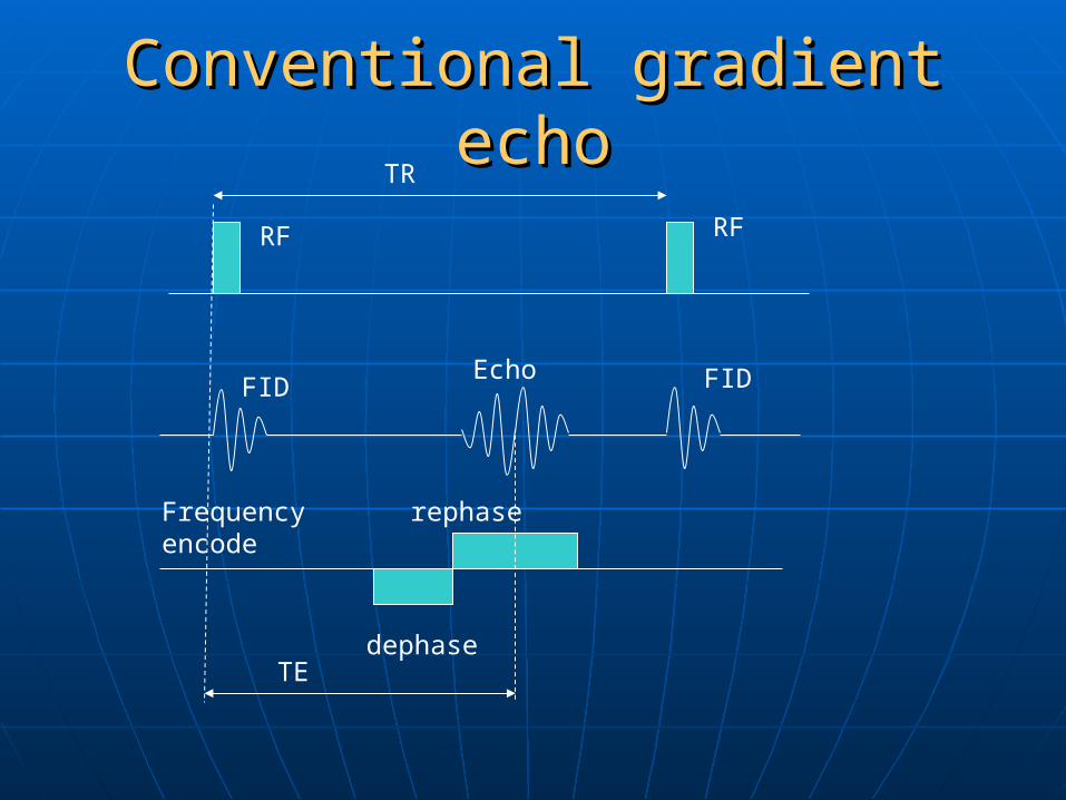
Conventional gradient echoConventional gradient echoTR
RF RF
FIDEcho
Frequency encode
dephase
rephase
TE
FID
Uses of gradient echoUses of gradient echo
Used for single slice breath-hold Used for single slice breath-hold acquisitions in the abdomenacquisitions in the abdomen
Used for dynamic contrast Used for dynamic contrast enhancementenhancement
Used to produce angiographic type Used to produce angiographic type images, because the flowing nuclei images, because the flowing nuclei which have been previously excited, which have been previously excited, always give a signal as gradient always give a signal as gradient rephasing is not slice selective.rephasing is not slice selective.
Manipulating Parameters Manipulating Parameters Flip angle and TR determines the degree Flip angle and TR determines the degree
of saturation and, therefore the T1 of saturation and, therefore the T1 weighting.weighting.
For saturation flip angle should be large For saturation flip angle should be large and TR short so that full recovery cannot and TR short so that full recovery cannot occur.occur.
To prevent saturation, flip angle should be To prevent saturation, flip angle should be small and the TR long enough to permit small and the TR long enough to permit full recovery.full recovery.
TE controls the amount of T2* dephasingTE controls the amount of T2* dephasing To minimize T2* Te should be shortTo minimize T2* Te should be short To maximize T2* TE should be long.To maximize T2* TE should be long.
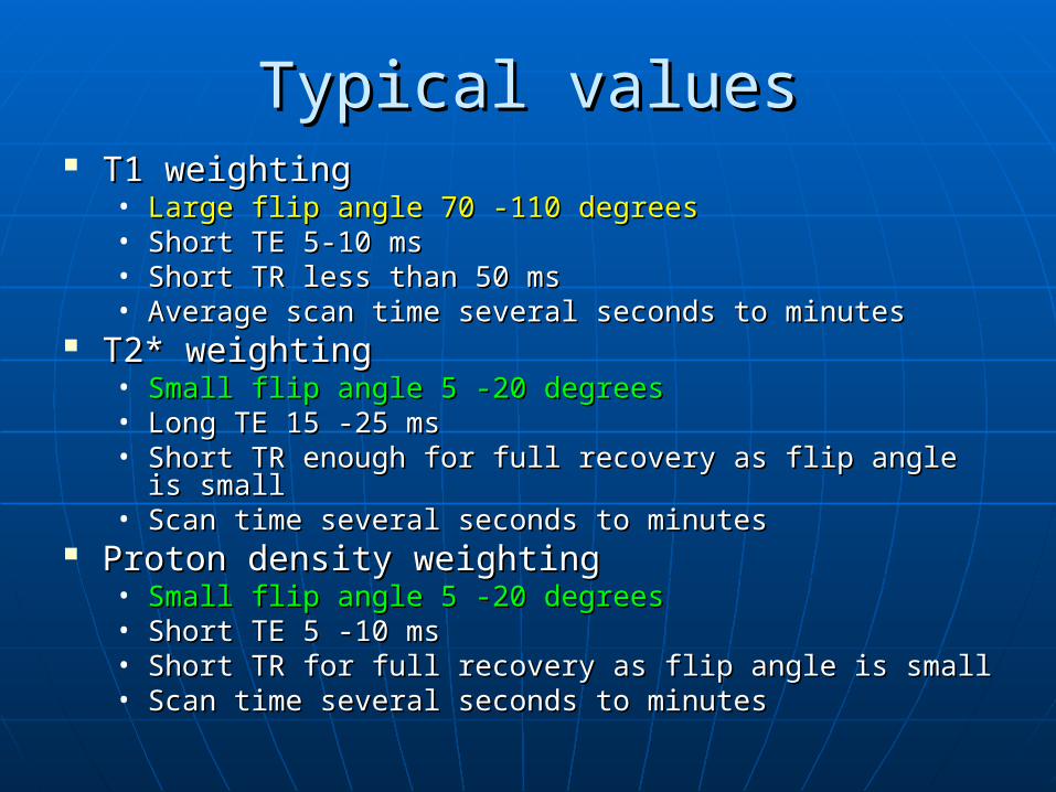
Typical valuesTypical values T1 weightingT1 weighting
• Large flip angle 70 -110 degreesLarge flip angle 70 -110 degrees• Short TE 5-10 msShort TE 5-10 ms• Short TR less than 50 msShort TR less than 50 ms• Average scan time several seconds to minutesAverage scan time several seconds to minutes
T2* weightingT2* weighting• Small flip angle 5 -20 degreesSmall flip angle 5 -20 degrees• Long TE 15 -25 msLong TE 15 -25 ms• Short TR enough for full recovery as flip angle is smallShort TR enough for full recovery as flip angle is small• Scan time several seconds to minutesScan time several seconds to minutes
Proton density weightingProton density weighting• Small flip angle 5 -20 degreesSmall flip angle 5 -20 degrees• Short TE 5 -10 msShort TE 5 -10 ms• Short TR for full recovery as flip angle is smallShort TR for full recovery as flip angle is small• Scan time several seconds to minutesScan time several seconds to minutes
The steady stateThe steady state This is a stage where the This is a stage where the TR is shorterTR is shorter than the than the
T1 and T2T1 and T2 times of the tissues. times of the tissues. There is no time for the transverse magnetization There is no time for the transverse magnetization
to decay, before the pulse sequence is repeatedto decay, before the pulse sequence is repeated There is coexistence of both longitudinal and There is coexistence of both longitudinal and
transverse magnetizationtransverse magnetization The flip angle and TR maintain the steady state The flip angle and TR maintain the steady state
which holds the longitudinal and transverse which holds the longitudinal and transverse components and the NMV steady during the data components and the NMV steady during the data acquisitionacquisition
Flip angles of 30Flip angles of 3000 to 45 to 4500 and TR of 20 to 50 ms and TR of 20 to 50 ms achieves a steady state. achieves a steady state.
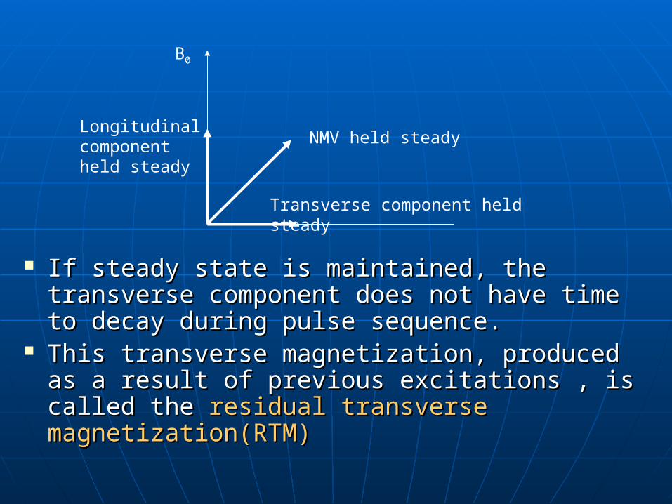
If steady state is maintained, the transverse If steady state is maintained, the transverse component does not have time to decay component does not have time to decay during pulse sequence.during pulse sequence.
This transverse magnetization, produced as a This transverse magnetization, produced as a result of previous excitations , is called the result of previous excitations , is called the residualresidual transverse magnetization(RTM)transverse magnetization(RTM)
B0
Longitudinal component held steady
Transverse component held steady
NMV held steady
The residual transverse magnetization The residual transverse magnetization ((RTMRTM) affects the contrast as it results in ) affects the contrast as it results in tissues with long T2 times , appearing tissues with long T2 times , appearing bright on the imagebright on the image
Most gradient echo sequences use the Most gradient echo sequences use the steady state, as the shortest TR and scan steady state, as the shortest TR and scan times are achieved.times are achieved.
Gradient echo sequences are Gradient echo sequences are classifiedclassified according to whether the according to whether the residual residual transverse magnetizationtransverse magnetization isis in phase in phase ((coherentcoherent) or out of phase () or out of phase (incoherentincoherent).).
Learning pointLearning point The steady state involves The steady state involves
repeatedly applying RF pulses at TR repeatedly applying RF pulses at TR less than the T1 and T2 of all tissuesless than the T1 and T2 of all tissues
This train of RF pulses generates This train of RF pulses generates two signalstwo signals1.1. A FID signal which occurs as a result of A FID signal which occurs as a result of
the withdrawal of the RF pulse and the withdrawal of the RF pulse and contains T2* informationcontains T2* information
2.2. A spin echo whose peak occurs at the A spin echo whose peak occurs at the same time as an RF pulsesame time as an RF pulse
This happens because This happens because every RF pulse every RF pulse contains individual radio wavescontains individual radio waves that have that have sufficient energy to rephase a previous FIDsufficient energy to rephase a previous FID
These radiowaves These radiowaves rephaserephase the RTM left the RTM left over from previous RF excitation pulses to over from previous RF excitation pulses to form a form a spin echospin echo. .
This ocurs at exactly the same time as the This ocurs at exactly the same time as the next RF pulse as the RTM takes the same next RF pulse as the RTM takes the same time to rephase as it took to dephase. time to rephase as it took to dephase. Therfore when utilizing steady state , the Therfore when utilizing steady state , the TR =TAU of the spin echo.TR =TAU of the spin echo.
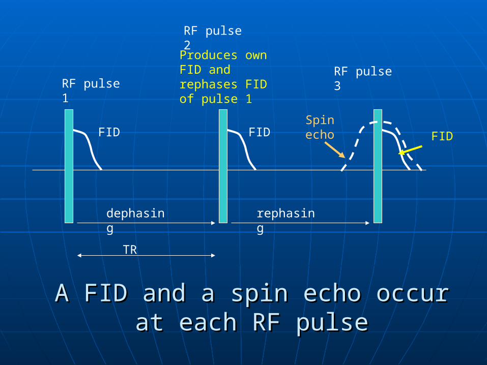
RF pulse 3
RF pulse 2
RF pulse 1
Produces own FID and rephases FID of pulse 1
FID FID FIDSpin echo
dephasing rephasing
TR
A FID and a spin echo occur at each A FID and a spin echo occur at each RF pulseRF pulse
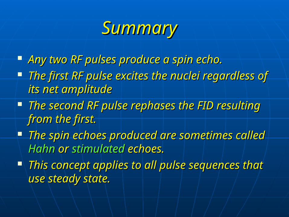
SummarySummary
Any two RF pulses produce a spin echo.Any two RF pulses produce a spin echo. The first RF pulse excites the nuclei The first RF pulse excites the nuclei
regardless of its net amplituderegardless of its net amplitude The second RF pulse rephases the FID The second RF pulse rephases the FID
resulting from the first.resulting from the first. The spin echoes produced are sometimes The spin echoes produced are sometimes
called called HahnHahn or or stimulatedstimulated echoes. echoes. This concept applies to all pulse This concept applies to all pulse
sequences that use steady state.sequences that use steady state.

GE-Coherent residual transverse GE-Coherent residual transverse magnetizationmagnetization
This pulse sequence uses a variable flip This pulse sequence uses a variable flip angle excitation pulse followed by gradient angle excitation pulse followed by gradient rephasing, to produce a gradient echo.rephasing, to produce a gradient echo.
Steady state is maintained by selecting TR Steady state is maintained by selecting TR shorter than T1 and T2shorter than T1 and T2
There is therefore RTM left over when the There is therefore RTM left over when the next excitation pulse is applied.next excitation pulse is applied.
The RTM is kept The RTM is kept coherentcoherent by a process by a process known as known as rewindingrewinding..
RewindingRewinding is achieved by reversing is achieved by reversing the slope of the phase encoding the slope of the phase encoding gradient after readout.gradient after readout.
This results in RTM rephasing, so that This results in RTM rephasing, so that it is in phase at the beginning of the it is in phase at the beginning of the next repetitionnext repetition
This alows the RTM to build up so This alows the RTM to build up so that tissues with a long T2 time that tissues with a long T2 time produce a high signal.produce a high signal.
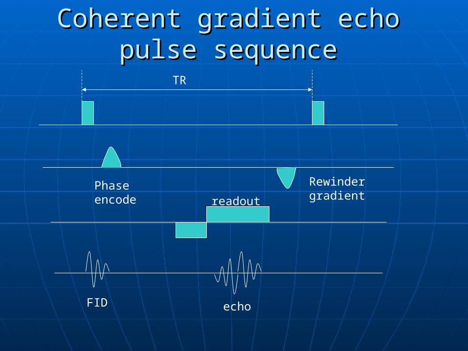
Coherent gradient echo pulse Coherent gradient echo pulse sequencesequenceTR
Phase encode
Rewinder gradientreadout
FID echo
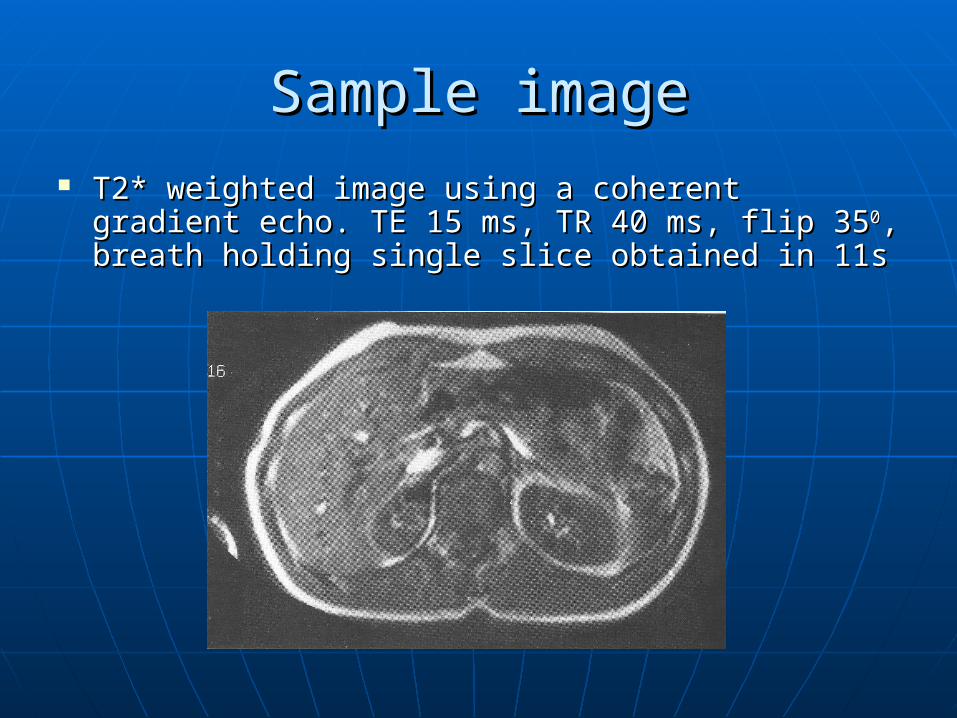
Sample imageSample image T2* weighted image using a coherent gradient T2* weighted image using a coherent gradient
echo. TE 15 ms, TR 40 ms, flip 35echo. TE 15 ms, TR 40 ms, flip 3500, breath holding , breath holding single slice obtained in 11ssingle slice obtained in 11s
Uses of coherent gradient echo Uses of coherent gradient echo This pulse sequences produce This pulse sequences produce T2*T2*
weighted images.weighted images. As As fluid is brightfluid is bright they give an they give an
angiographic, myelographic or angiographic, myelographic or arthrographic effect.arthrographic effect.
Can be used to determine whether a Can be used to determine whether a vesselvessel is patentis patent, or whether an area , or whether an area contains fluid.contains fluid.
Can be acquired slice by slice, or in a 3D Can be acquired slice by slice, or in a 3D volume acquisitionvolume acquisition
As the TR is short, a sliice can be acquired As the TR is short, a sliice can be acquired in a single breath hold.in a single breath hold.
Parameters Parameters To maintain the steady stateTo maintain the steady state
• Flip angles 30 – 45Flip angles 30 – 45• TR 20-50 msTR 20-50 ms
To maximize T2* long TE 15- 25 msTo maximize T2* long TE 15- 25 ms Use gradient moment rephasing to Use gradient moment rephasing to
accentuate T2*accentuate T2* Average scan timeAverage scan time
• Seconds for single sliceSeconds for single slice• 4-15 min for volumes4-15 min for volumes
(to minimize T2* to produce T1 or proton (to minimize T2* to produce T1 or proton density weighting TE should be the density weighting TE should be the shortest possible)shortest possible)
AdvantagesAdvantages & & DisadvantagesDisadvantages
Very fast scans, Very fast scans, breath holding breath holding possiblepossible
Very sensitive to Very sensitive to flow so good for flow so good for angiographyangiography
Can be acquired in Can be acquired in a volume a volume acquisitionacquisition
Poor SNR in 2D Poor SNR in 2D acquisitionsacquisitions
Magnetic Magnetic susceptibility susceptibility increasesincreases
Loud gradient Loud gradient noisenoise
Incoherent(spoiled) RTMIncoherent(spoiled) RTM Pulse sequence that use incoherent RTM Pulse sequence that use incoherent RTM
begin with a variable flip angle excitation begin with a variable flip angle excitation pulse, and use gradient rephasing to pulse, and use gradient rephasing to produce agrdient echo.produce agrdient echo.
The steady state is maintained so that The steady state is maintained so that RTM is left over from the previuos RF.RTM is left over from the previuos RF.
The The RTM is spoiledRTM is spoiled so that its effect on so that its effect on image contrast is minimal.image contrast is minimal.
There are two ways to achieve spoilingThere are two ways to achieve spoiling• Digitized RF spoilingDigitized RF spoiling• Gradient spoilingGradient spoiling
RF spoilingRF spoiling RF spoiling is achived by RF spoiling is achived by controlingcontroling the the phasephase of of
the the digitised RF pulses that are transmitted.digitised RF pulses that are transmitted. The digitizedThe digitized RF RF is transmitted at a is transmitted at a specific specific
frequencyfrequency & & phasephase The resultant NMV and transverse component are The resultant NMV and transverse component are
fillped to a certain position in the transvere plane.fillped to a certain position in the transvere plane. The The receiver coil can lock onto the phasereceiver coil can lock onto the phase of the of the
RF that has just being transmitted and receives RF that has just being transmitted and receives only signal at that phase.only signal at that phase.
Transverse magnetization at other phases or Transverse magnetization at other phases or positions in the transverse plane are not recived positions in the transverse plane are not recived by the coil by the coil
Each RF is delivered at a different Each RF is delivered at a different phase and the receiver coil is locked phase and the receiver coil is locked to recieve signal only at that phaseto recieve signal only at that phase
This process continues and the TRM This process continues and the TRM which is at a different phase is which is at a different phase is ignored by the receiver coil.ignored by the receiver coil.
So the effect of RTM on the image is So the effect of RTM on the image is eleminated.eleminated.
T2* is therefore cannot predominate T2* is therefore cannot predominate and T1 and proton density weighting and T1 and proton density weighting prevails.prevails.
UsesUses
RF spoild GE pulse sequencs produce RF spoild GE pulse sequencs produce T1 or proton density weited images, T1 or proton density weited images, although fluid may have a rather although fluid may have a rather high signal due to gradient rephasinghigh signal due to gradient rephasing
Can be used for 2D and volume Can be used for 2D and volume acquisition and as the TR is short the acquisition and as the TR is short the 2D acquisition can be used to acquire 2D acquisition can be used to acquire T1 weighted breath-hold images.T1 weighted breath-hold images.
Demonstrate good T1 anatomyDemonstrate good T1 anatomy
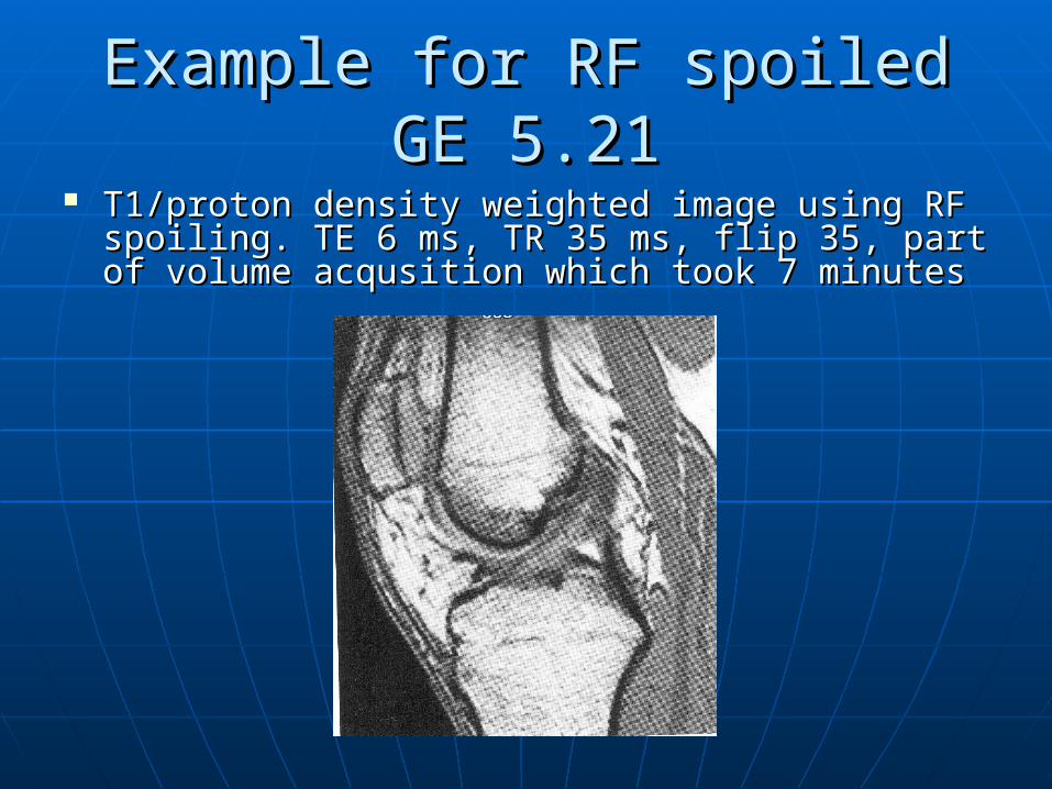
Example for RF spoiled GE 5.21Example for RF spoiled GE 5.21 T1/proton density weighted image using RF T1/proton density weighted image using RF
spoiling. TE 6 ms, TR 35 ms, flip 35, part of spoiling. TE 6 ms, TR 35 ms, flip 35, part of volume acqusition which took 7 minutesvolume acqusition which took 7 minutes
Parameters Parameters
To maintain steady stateTo maintain steady state• Flip angle 30-45Flip angle 30-45• TR 20-50 msTR 20-50 ms
To maximise T1 ; short TE 5-10msTo maximise T1 ; short TE 5-10ms Average scan time; several seconds for Average scan time; several seconds for
single slice, 4-15 min for volumessingle slice, 4-15 min for volumes AdvantagesAdvantages
• Can be acquired in a volume or 2DCan be acquired in a volume or 2D• Breath holding possibleBreath holding possible• Good SNR and anatomical detail in volumesGood SNR and anatomical detail in volumes
Gradient spoilingGradient spoiling Gradient spoiling is the Gradient spoiling is the oppositeopposite of of rewindingrewinding.. The slice select, phase encoding, and frequency The slice select, phase encoding, and frequency
encoding gradients can be used to dephase the encoding gradients can be used to dephase the RTM, so that it is incoherent at the beginning of RTM, so that it is incoherent at the beginning of the next repetition.the next repetition.
T2* effects are reducedT2* effects are reduced Uses and parameters are similar to those in RF Uses and parameters are similar to those in RF
spoiling.spoiling. Can be used to achieve T2* when the Can be used to achieve T2* when the
parameteres are similar to those in conventional parameteres are similar to those in conventional GE.(because GS is less efficient than RF spoiling GE.(because GS is less efficient than RF spoiling and moreT2* information is present in the signal)and moreT2* information is present in the signal)
Steady state free prcession (SSFP)Steady state free prcession (SSFP)
Can be used to get shortest possible TR Can be used to get shortest possible TR and scan time with steady state GEand scan time with steady state GE
Used to produce more T2 weighted images Used to produce more T2 weighted images than conventional gradient echo than conventional gradient echo sequences.sequences.
The pulse sequences used here help to The pulse sequences used here help to obtain images that have a sufficiently long obtain images that have a sufficiently long TE and less T2* when using steady state TE and less T2* when using steady state than other gradient echo pulse sequences.than other gradient echo pulse sequences.
This is achieved in the manner described This is achieved in the manner described below.below.
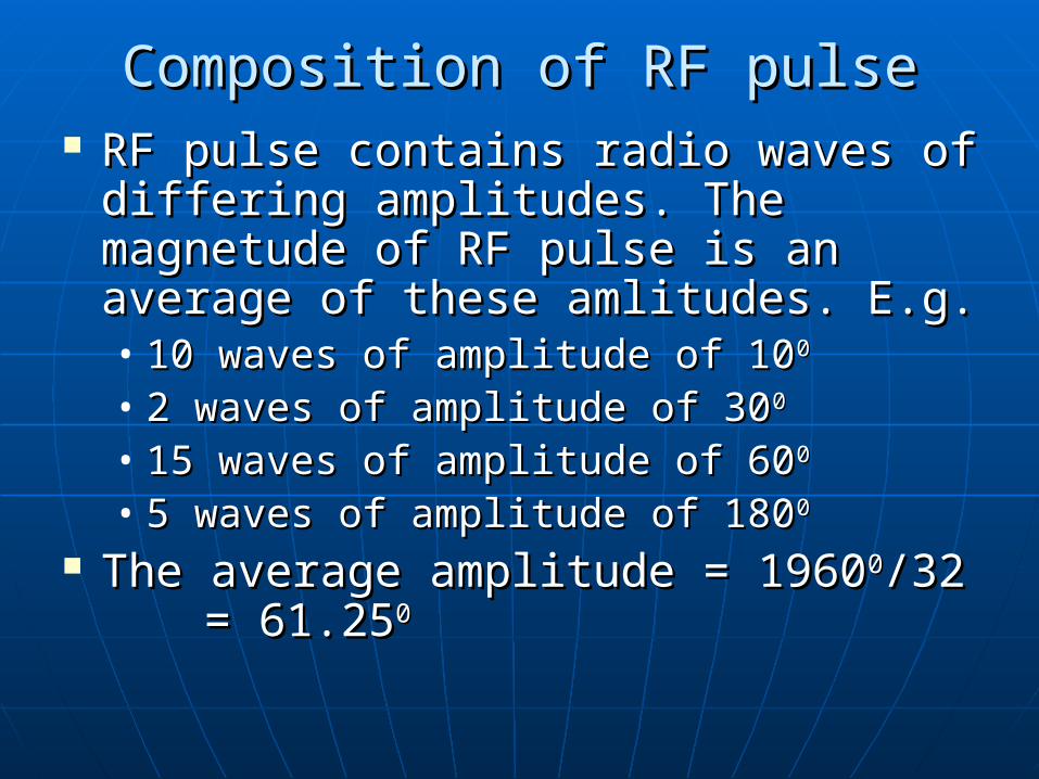
Composition of RF pulseComposition of RF pulse RF pulse contains radio waves of RF pulse contains radio waves of
differing amplitudes. The magnetude differing amplitudes. The magnetude of RF pulse is an average of these of RF pulse is an average of these amlitudes. E.g.amlitudes. E.g.• 10 waves of amplitude of 1010 waves of amplitude of 1000
• 2 waves of amplitude of 302 waves of amplitude of 3000
• 15 waves of amplitude of 6015 waves of amplitude of 6000
• 5 waves of amplitude of 1805 waves of amplitude of 18000
The average amplitude = 1960The average amplitude = 196000/32 /32 = 61.25= 61.2500
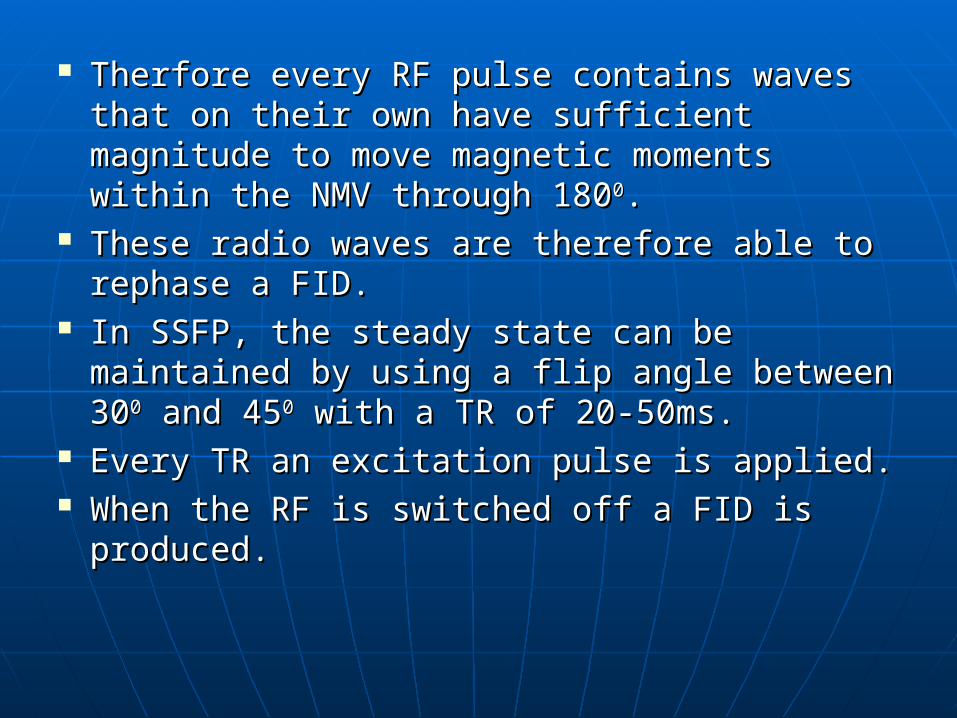
Therfore every RF pulse contains waves Therfore every RF pulse contains waves that on their own have sufficient that on their own have sufficient magnitude to move magnetic moments magnitude to move magnetic moments within the NMV through 180within the NMV through 18000..
These radio waves are therefore able to These radio waves are therefore able to rephase a FID.rephase a FID.
In SSFP, the steady state can be In SSFP, the steady state can be maintained by using a flip angle between maintained by using a flip angle between 303000 and 45 and 4500 with a TR of 20-50ms. with a TR of 20-50ms.
Every TR an excitation pulse is applied.Every TR an excitation pulse is applied. When the RF is switched off a FID is When the RF is switched off a FID is
produced.produced.
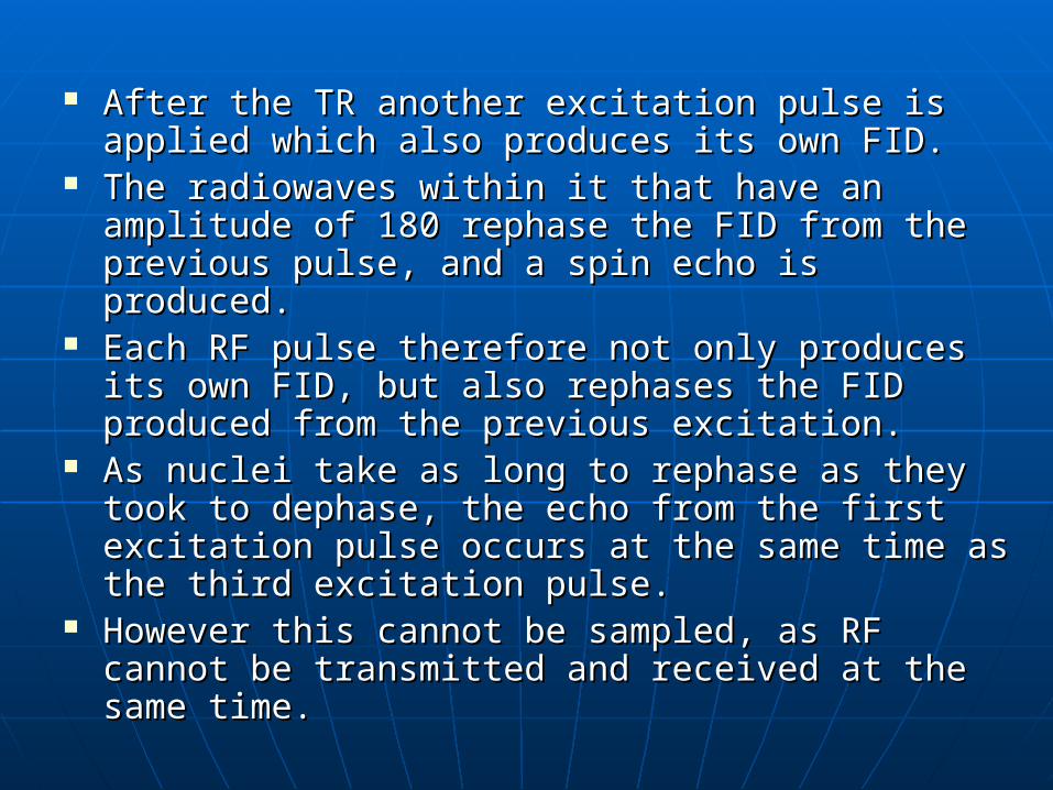
After the TR another excitation pulse is applied After the TR another excitation pulse is applied which also produces its own FID.which also produces its own FID.
The radiowaves within it that have an amplitude of The radiowaves within it that have an amplitude of 180 rephase the FID from the previous pulse, and a 180 rephase the FID from the previous pulse, and a spin echo is produced.spin echo is produced.
Each RF pulse therefore not only produces its own Each RF pulse therefore not only produces its own FID, but also rephases the FID produced from the FID, but also rephases the FID produced from the previous excitation.previous excitation.
As nuclei take as long to rephase as they took to As nuclei take as long to rephase as they took to dephase, the echo from the first excitation pulse dephase, the echo from the first excitation pulse occurs at the same time as the third excitation occurs at the same time as the third excitation pulse.pulse.
However this cannot be sampled, as RF cannot be However this cannot be sampled, as RF cannot be transmitted and received at the same time.transmitted and received at the same time.
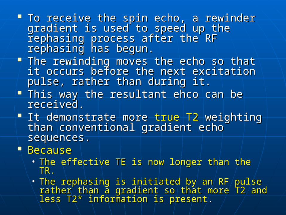
To receive the spin echo, a rewinder To receive the spin echo, a rewinder gradient is used to speed up the rephasing gradient is used to speed up the rephasing process after the RF rephasing has begun.process after the RF rephasing has begun.
The rewinding moves the echo so that it The rewinding moves the echo so that it occurs before the next excitation pulse, occurs before the next excitation pulse, rather than during it.rather than during it.
This way the resultant ehco can be This way the resultant ehco can be received.received.
It demonstrate more It demonstrate more true T2true T2 weighting weighting than conventional gradient echo than conventional gradient echo sequences.sequences.
BecauseBecause• The effective TE is now longer than the TR.The effective TE is now longer than the TR.• The rephasing is initiated by an RF pulse rather The rephasing is initiated by an RF pulse rather
than a gradient so that more T2 and less T2* than a gradient so that more T2 and less T2* information is presentinformation is present..
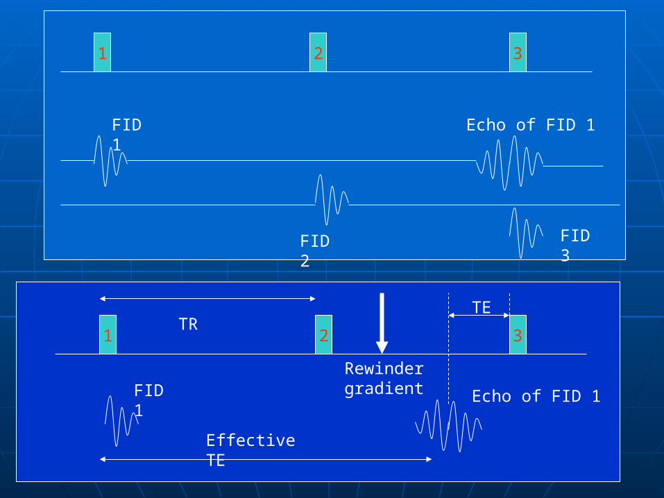
1 32
1 32
FID 1
FID 2
Echo of FID 1
FID 3
Rewinder gradient
TR
Effective TE
TE
FID 1 Echo of FID 1
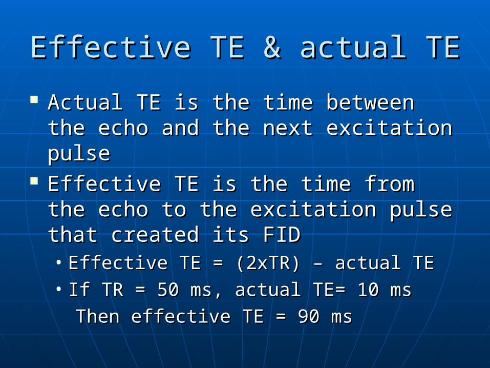
Effective TE & actual TEEffective TE & actual TE
Actual TE is the time between the Actual TE is the time between the echo and the next excitation pulseecho and the next excitation pulse
Effective TE is the time from the echo Effective TE is the time from the echo to the excitation pulse that created to the excitation pulse that created its FIDits FID• Effective TE = (2xTR) – actual TEEffective TE = (2xTR) – actual TE• If TR = 50 ms, actual TE= 10 msIf TR = 50 ms, actual TE= 10 ms
Then effective TE = 90 msThen effective TE = 90 ms
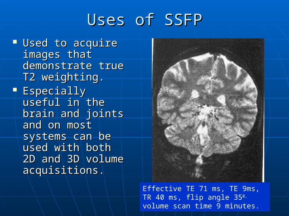
Uses of SSFPUses of SSFP Used to acquire Used to acquire
images that images that demonstrate true demonstrate true T2 weighting.T2 weighting.
Especially useful Especially useful in the brain and in the brain and joints and on most joints and on most systems can be systems can be used with both 2D used with both 2D and 3D volume and 3D volume acquisitions.acquisitions.
Effective TE 71 ms, TE 9ms, TR 40 ms, flip angle 350, volume scan time 9 minutes.
ParametersParameters To maintain steady state; flip angle 30-45, To maintain steady state; flip angle 30-45,
TR 20-50 msTR 20-50 ms Actual TE affects the effective TE unless Actual TE affects the effective TE unless
the system uses a fixed TE. the system uses a fixed TE. Average scan time 4-15 min volume Average scan time 4-15 min volume
acquisitionacquisition Some manufacturers suggest decreasing Some manufacturers suggest decreasing
the effective TE to reduce magnetic the effective TE to reduce magnetic susceptibility, and increasing the flip angle susceptibility, and increasing the flip angle to create more transverse magnetisation to create more transverse magnetisation which results in higher SNR which results in higher SNR
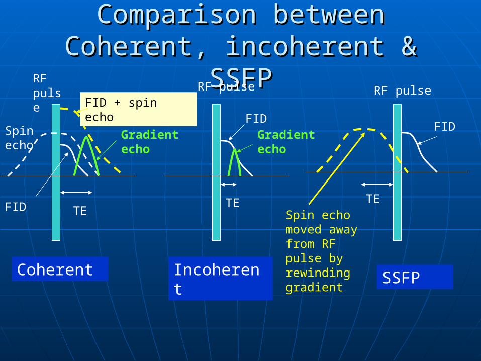
Comparison between Coherent, Comparison between Coherent, incoherent & SSFPincoherent & SSFP
FID + spin echo
Spin echo
FID TE
Gradient echo
FIDFID
Gradient echo
Spin echo moved away from RF pulse by rewinding gradient
RF pulse RF pulse RF pulse
TETE
Coherent Incoherent SSFP
Ultra-fast sequencesUltra-fast sequences Advances have been made in developing Advances have been made in developing
very fast pulse sequences.very fast pulse sequences. Usually Usually employemploy the the coherentcoherent or or incoherentincoherent
gradient echo sequences.gradient echo sequences. The TE is significantly reduced by:The TE is significantly reduced by:
• Aplying only a portion of the RF exciation Aplying only a portion of the RF exciation pulse.pulse.
• Reading only a portion of the echoReading only a portion of the echo TETE kept to a minimum ( kept to a minimum (2.5 – 3.0 ms2.5 – 3.0 ms)) TRTR andand therefore the therefore the scan time is reduced.scan time is reduced. TR as low as 10 ms is achieved and about TR as low as 10 ms is achieved and about
16 slices can be achieved in a single 16 slices can be achieved in a single breath hold.breath hold.
Many ultra-fast sequences use extra Many ultra-fast sequences use extra pulses applied before the pulse sequences pulses applied before the pulse sequences begins, to pre-magnetise the tissue.begins, to pre-magnetise the tissue.
This way certain contrast can be obtained.This way certain contrast can be obtained. Pre-magnetisation is achieved in the Pre-magnetisation is achieved in the
following manner.following manner.• Applying a 180Applying a 18000 pulse before the pulse pulse before the pulse
sequence and a specified delay time similar to sequence and a specified delay time similar to inversion recovery.inversion recovery.
• Applying a combination of 90Applying a combination of 9000/180/18000/90/9000 pulses pulses before the pulse sequence begins.before the pulse sequence begins.
(first 90 pulse produces transverse (first 90 pulse produces transverse magnetisation. 180 pulse rephases this, magnetisation. 180 pulse rephases this, and at a specific time later second 90 and at a specific time later second 90 pulse is applied. This drives the coherent pulse is applied. This drives the coherent transverse magnetisation into the transverse magnetisation into the longitudinal plane. It is available to be longitudinal plane. It is available to be fliped when the pulse sequence begins. fliped when the pulse sequence begins. This is used to produce T2 contrast and is This is used to produce T2 contrast and is sometimes known as driven equilibrium)sometimes known as driven equilibrium)
Echo planer imaging(EPI)Echo planer imaging(EPI)
Fills all the lines of k-space during one TR Fills all the lines of k-space during one TR Uses a single echo trainUses a single echo train Multiple Echos are generated and each is Multiple Echos are generated and each is
phase encoded by a different slope of phase encoded by a different slope of gradient to fill all the required lines of k gradient to fill all the required lines of k space.space.
Echoes are generated either by 180 Echoes are generated either by 180 rephasing pulses or by gradients.rephasing pulses or by gradients.
Gradients are much fasterGradients are much faster