Application of ESD S20.20 to Semiconductor S20.20 Equipment Manufacturers lProgram ensures that...
29
Application of ANSI/ESD S20.20 to Application of ANSI/ESD S20.20 to Semiconductor Manufacturing Semiconductor Manufacturing Carl Newberg River’s Edge Technical Service, Inc. www.retsinc.com
Transcript of Application of ESD S20.20 to Semiconductor S20.20 Equipment Manufacturers lProgram ensures that...

Application of ANSI/ESD S20.20 toApplication of ANSI/ESD S20.20 toSemiconductor ManufacturingSemiconductor Manufacturing
Carl Newberg
River’s Edge Technical Service, Inc.
www.retsinc.com

AcknowledgementsAcknowledgements
We would like to acknowledge Patrick Lim of3M for many of the drawings used in thispresentation.
Many thanks to Patrick and 3M for theirwillingness to allow the use of theirdrawings.

What Is ANSI/ESD S20.20?What Is ANSI/ESD S20.20?
l ANSI/ESD S20.20 defines a companiesESD control program
l Can be equated with (and actually isbecoming a part of) ISO 9000 qualityprograms
l Applies to areas handling devices down to100 volts (HBM).

ANSI/ESD S20.20ANSI/ESD S20.20
Applying ANSI/ESD S20.20 to semiconductormanufacturers
l Equipment Manufacturers
l Semiconductor Manufacturers/Processors

ANSI/ESD S20.20ANSI/ESD S20.20
Equipment Manufacturers
l Program ensures thatequipment is manu-factured in a high qualityESD controlled environ-ment
l Protects Customers fromequipment deliverydelays and latent failures
Semiconductor Manufacturers
l Prevents equipment lockupproblems
l Increased yield due to ESDdamage and electrostaticcharge contamination
l Protects customers fromlatent failures

ANSI/ESD S20.20 & SEMI E-78ANSI/ESD S20.20 & SEMI E-78
l Not explicitly stated
l SEMI E-78 ties into S20.20– Grounding/Bonding
– Electric Fieldsl Materials
l Ionization
l E-78 has some additional elements notcalled out in S20.20

Overview of ANSI/ESD S20.20Overview of ANSI/ESD S20.20
Goal: Provide continuous ESD protection
l Administrative Requirements– The “Plan”
– Training
– Compliance Verification (Audits/Inspections)
l Technical Requirements
l Tailoring
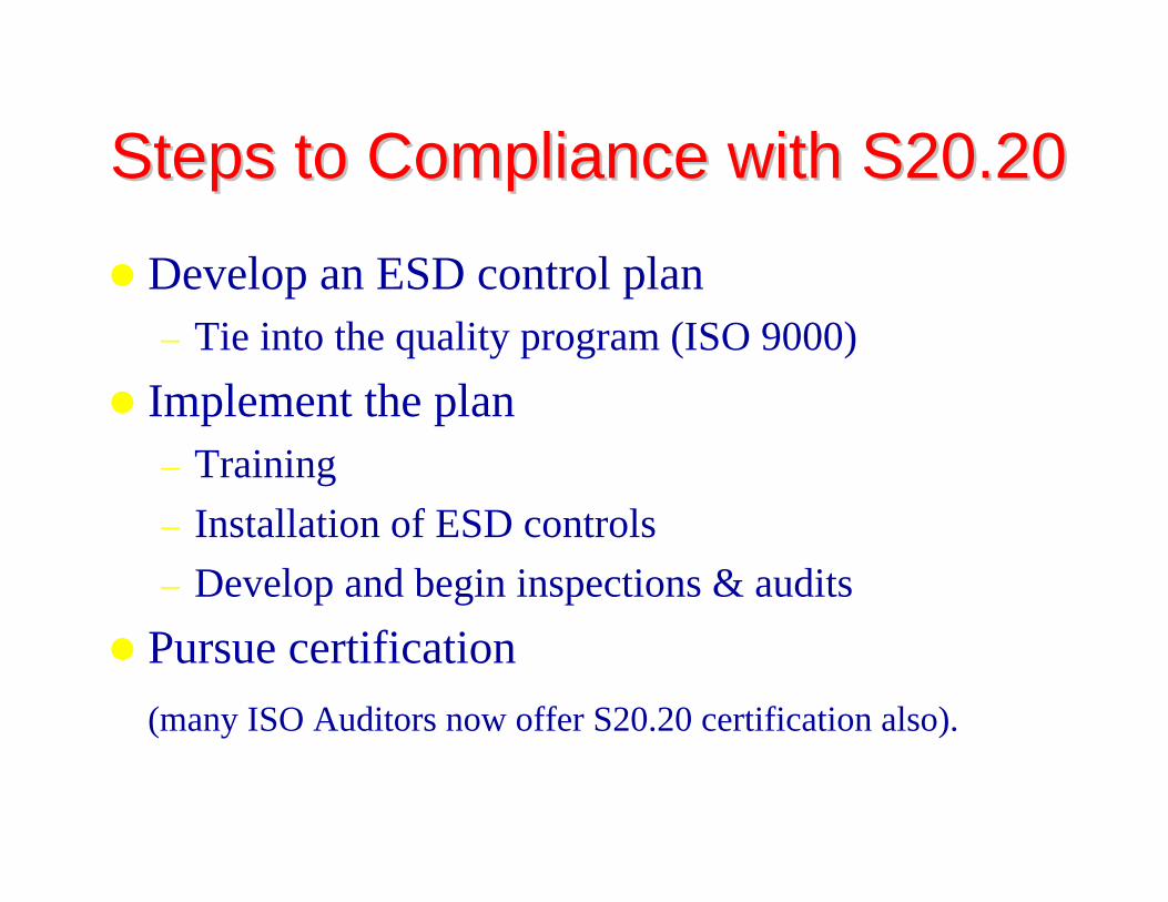
Steps to Compliance with S20.20Steps to Compliance with S20.20
l Develop an ESD control plan– Tie into the quality program (ISO 9000)
l Implement the plan– Training
– Installation of ESD controls
– Develop and begin inspections & audits
l Pursue certification
(many ISO Auditors now offer S20.20 certification also).

The ESD Control PlanThe ESD Control Plan
The Plan should address each of therequirements of the program
l Training
l Compliance Verification
l Technical Requirements
l Organizational Requirements
l Contractual Obligations
The Training PlanThe Training Plan
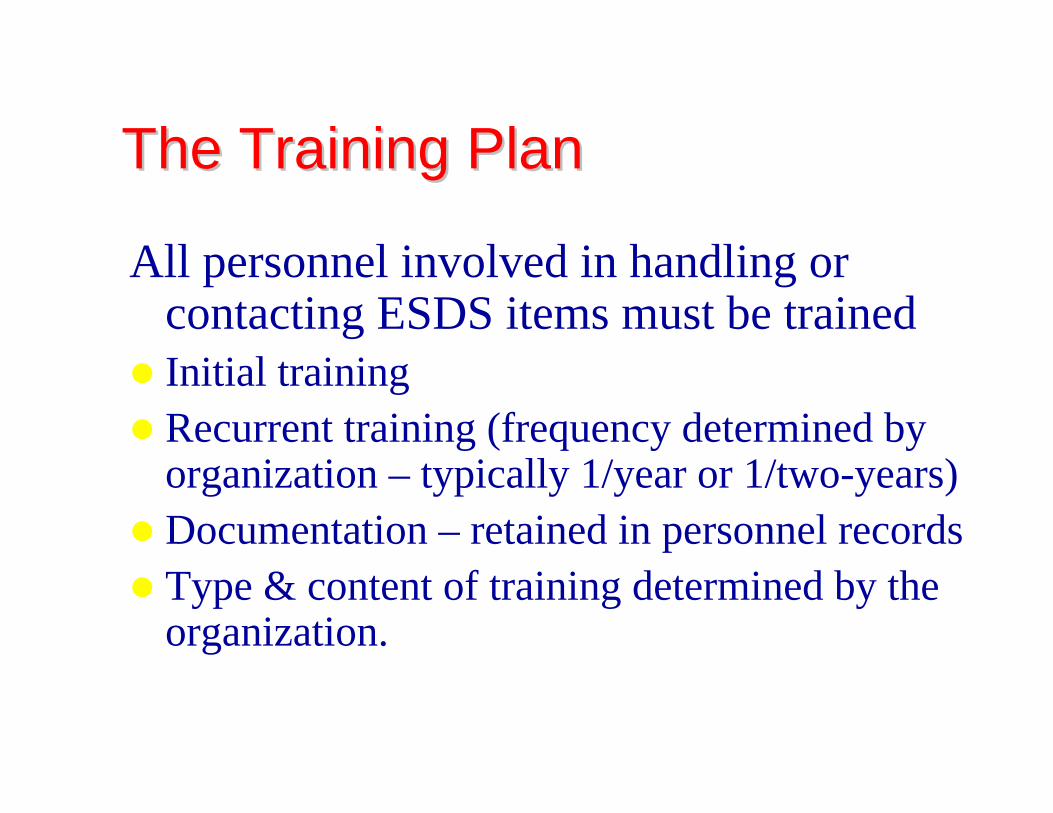
All personnel involved in handling orcontacting ESDS items must be trained
l Initial trainingl Recurrent training (frequency determined by
organization – typically 1/year or 1/two-years)l Documentation – retained in personnel recordsl Type & content of training determined by the
organization.

Compliance Verification PlanCompliance Verification Plan
This makes sure the program continues to work
lInternal Audits– Inspections
l Frequency depends upon sensitivity and cost of failure
l Typically performed by internal personnel
– Audits
lExternal Audits

Technical RequirementsTechnical Requirements
l Grounding / Bonding Systems
l Personnel Grounding
l Protected Areas
l Packaging
lMarking
l Equipment
l Handling

Grounding / Bonding SystemsGrounding / Bonding Systems
Equipment Ground
Auxiliary Ground
Equipotential Bonding
Common Point Ground
< 1.0 Ω (AC Impedance)
< 1.0 Ω (AC Impedance)
< 1.0 x 10⁹ Ω
< 1.0 Ω (AC Impedance)
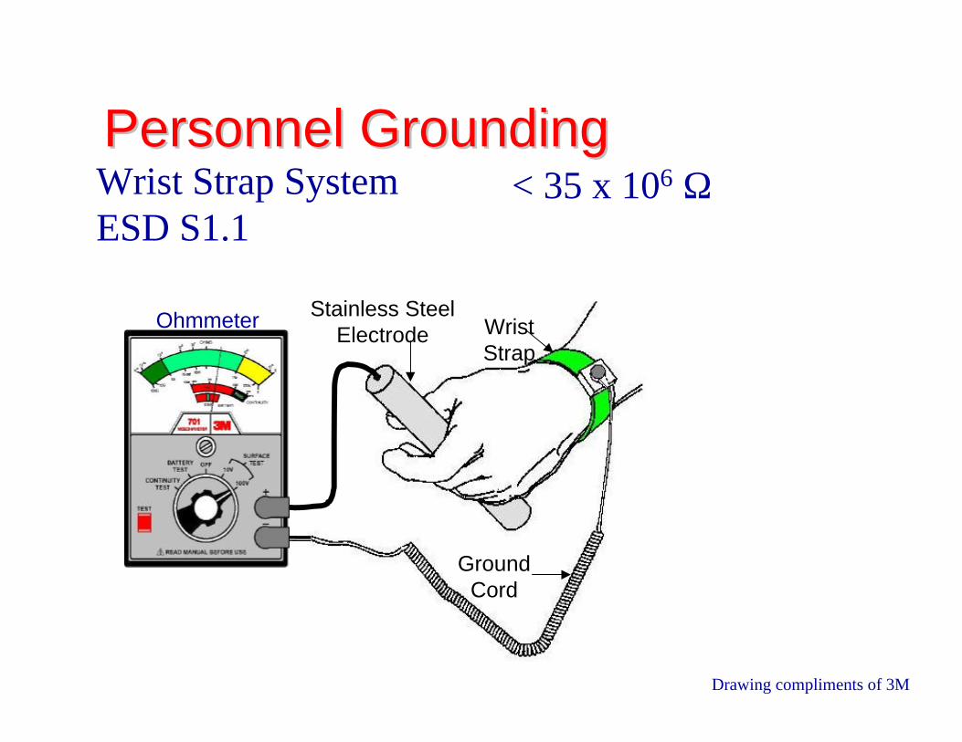
Personnel GroundingPersonnel GroundingWrist Strap SystemESD S1.1
< 35 x 106 Ω
Ohmmeter Stainless SteelElectrode
GroundCord
WristStrap
Drawing compliments of 3M
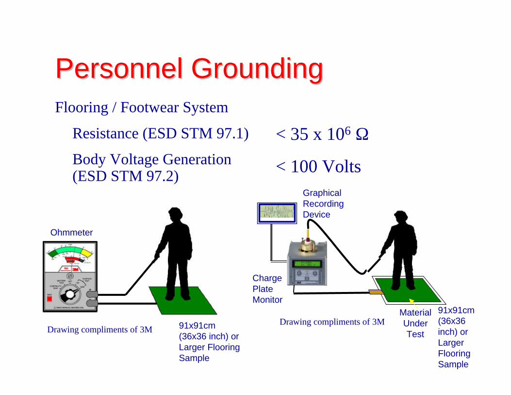
Personnel GroundingPersonnel GroundingFlooring / Footwear System
Resistance (ESD STM 97.1)
Body Voltage Generation(ESD STM 97.2)
< 35 x 106 Ω
< 100 Volts
Ohmmeter
91x91cm(36x36 inch) orLarger FlooringSample
91x91cm(36x36inch) orLargerFlooringSample
MaterialUnderTest
GraphicalRecordingDevice
ChargePlateMonitor
Drawing compliments of 3MDrawing compliments of 3M

Protected AreaProtected Area• Work Surface
• Wrist Strap Cord
• Footwear
• Flooring
• Seating
• Ionization (other thanroom systems)
• Ionization (roomsystems)
< 1.0 x 10⁹ Ω or < 200 Volts
0.8 x 10⁶ - 1.2 x 10⁶ Ω
< 1.0 x 10⁹ Ω
< 1.0 x 10⁹ Ω
< 1.0 x 10⁹ Ω
< + 50 Volts Voltage Offset
< + 150 Volts Voltage Offset

Protected Area (Continued)Protected Area (Continued)• Mobile Equipment
• Continuous Monitors
• Signs
• Equipment
• AC Powered Tools
• Battery Powered andPneumatic Hand Tools
• Garment
• Humidity
< 1.0 x 10⁹ Ω
Manufacturer Specification
Required
< 1.0 Ω
< 1.0 x 10¹² Ω
1 x 10⁵Ω > Resistance <1 x 10¹¹Ω
30% < RH < 70%

PackagingPackaging• Conductive
• Dissipative
• Shielding
• Low Charging
• Protective Material Marking
< 1.0 x 10⁴ Ω
> 1 x 10⁴ to < 1 x 10¹¹ Ω
< 50 nJ
ESD ADV 11.2
EOS/ESD S8.1

Ohmmeter
Work Surfaces (ESD S4.1)
R < 1 x 10⁹ ohm
2”
2”
3”
A
B C
D
E
To: A, B, C, D, E
Resistance-to-Groundable Point - New Installations
Slide compliments of 3M
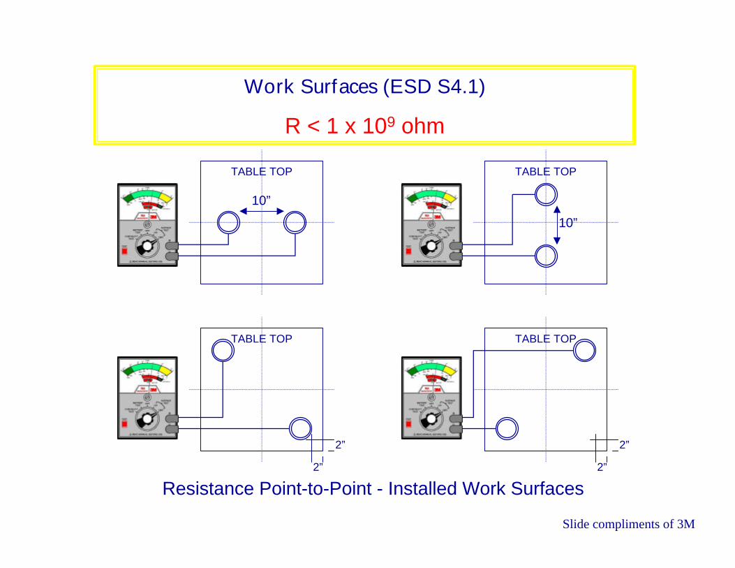
Work Surfaces (ESD S4.1)
R < 1 x 10⁹ ohm
Resistance Point-to-Point - Installed Work Surfaces
10”
TABLE TOP
10”
TABLE TOP
TABLE TOP TABLE TOP
2”
2”
2”
2”
Slide compliments of 3M

Footwear (ESD S9.1)
R < 1 x 10⁹ ohm
Ohmmeter
Stainless SteelPlate
Insulator
AluminumFoil
One Sock Inside the Other Filled with Shot
Footwear Under Test
Slide compliments of 3M

Flooring (ANSI/ESD S7.1)
R < 1 x 10⁹ ohm
3
1 5
42
Resistance to Groundable Point Measurement
6
Groundable Point BGroundable Point A
Electrode (5 lbs, 2.5” dia)
Slide compliments of 3M

Flooring (ANSI/ESD S7.1)
R < 1 x 10⁹ ohm
3
1 5
42
Point to Point Resistance Measurement
6
A B
PositionPosition
Slide compliments of 3M

Seating (ESD STM 12.1)
1 x 10⁵ ohm < R < 1 x 10⁹ ohm
Ohmmeter
5”x10” Foot Plate
Electrode A
Electrode B
Back RestRear of Back Rest
Seat
Conductive Casters
Foot Rest
Drag Chain
Base
Resistance to Groundable Point PositionsSlide compliments of 3M

Seating (ESD STM 12.1)
1 x 10⁵ ohm < R < 1 x 10⁹ ohm
1
2
3 4
51
2
1
2
3 4
5
1
2 3
Seat Back Rest
Rear of Back Rest Arm Rest
Foot Rest
Any Location
1
2
3
4
5
Base with PlasticCovering
Note: If base is baremetal, test only atPosition 1.
Seating Component Test Positions Slide compliments of 3M

Ionization (ANSI EOS/ESD S3.1)
Offset Voltage < + 50 volts
Test Locations for Overhead Ionizer
Overhead Ionizer
60 cm(24”)
45 cm(18”)
15 cm(6”)
Work Surface
Center Line of Test Points
Air Flow
Charge PlateMonitor (CPM)
6”x6” Plate
Slide compliments of 3M

Ionization (ANSI EOS/ESD S3.1)
Offset Voltage < + 50 volts
Test Locations for Bench Top Ionizer
Work Surface
15 cm(6”)
Air Flow
Bench Top Ionizer
30 cm(12”)
30 cm(12”)
30 cm(12”)
30 cm(12”)
Slide compliments of 3M
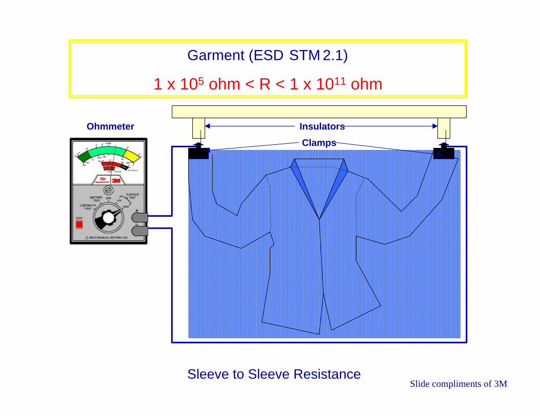
Garment (ESD STM 2.1)
1 x 10⁵ ohm < R < 1 x 10¹¹ ohm
Ohmmeter
Sleeve to Sleeve Resistance
Insulators
Clamps
Slide compliments of 3M

Garment (ESD STM 2.1)
1 x 10⁵ ohm < R < 1 x 10¹¹ ohm
Ohmmeter
Point to Point Resistance
Five Pound Electrodes
Insulative Surface
Slide compliments of 3M