Application manual, Busbar protection REB670 2.0, · PDF fileDisclaimer The data, examples and...
498
Relion ® 670 series Busbar protection REB670 2.0 ANSI Application Manual
Transcript of Application manual, Busbar protection REB670 2.0, · PDF fileDisclaimer The data, examples and...

Relion® 670 series
Busbar protection REB670 2.0 ANSIApplication Manual


Document ID: 1MRK 505 302-UUSIssued: May 2014
Revision: -Product version: 2.0
© Copyright 2014 ABB. All rights reserved

CopyrightThis document and parts thereof must not be reproduced or copied without writtenpermission from ABB, and the contents thereof must not be imparted to a third party,nor used for any unauthorized purpose.
The software and hardware described in this document is furnished under a license andmay be used or disclosed only in accordance with the terms of such license.
This product includes software developed by the OpenSSL Project for use in theOpenSSL Toolkit. (http://www.openssl.org/)
This product includes cryptographic software written/developed by: Eric Young([email protected]) and Tim Hudson ([email protected]).
TrademarksABB and Relion are registered trademarks of the ABB Group. All other brand orproduct names mentioned in this document may be trademarks or registeredtrademarks of their respective holders.
WarrantyPlease inquire about the terms of warranty from your nearest ABB representative.

DisclaimerThe data, examples and diagrams in this manual are included solely for the concept orproduct description and are not to be deemed as a statement of guaranteed properties.All persons responsible for applying the equipment addressed in this manual mustsatisfy themselves that each intended application is suitable and acceptable, includingthat any applicable safety or other operational requirements are complied with. Inparticular, any risks in applications where a system failure and/or product failure wouldcreate a risk for harm to property or persons (including but not limited to personalinjuries or death) shall be the sole responsibility of the person or entity applying theequipment, and those so responsible are hereby requested to ensure that all measuresare taken to exclude or mitigate such risks.
This document has been carefully checked by ABB but deviations cannot becompletely ruled out. In case any errors are detected, the reader is kindly requested tonotify the manufacturer. Other than under explicit contractual commitments, in noevent shall ABB be responsible or liable for any loss or damage resulting from the useof this manual or the application of the equipment.

ConformityThis product complies with the directive of the Council of the European Communitieson the approximation of the laws of the Member States relating to electromagneticcompatibility (EMC Directive 2004/108/EC) and concerning electrical equipment foruse within specified voltage limits (Low-voltage directive 2006/95/EC). Thisconformity is the result of tests conducted by ABB in accordance with the productstandard EN 60255-26 for the EMC directive, and with the product standards EN60255-1 and EN 60255-27 for the low voltage directive. The product is designed inaccordance with the international standards of the IEC 60255 series and ANSI C37.90.

Table of contents
Section 1 Introduction..........................................................................17This manual............................................................................................17Intended audience..................................................................................17Product documentation...........................................................................18
Product documentation set................................................................18Document revision history.................................................................19Related documents............................................................................20
Document symbols and conventions......................................................20Symbols.............................................................................................20Document conventions......................................................................21IEC61850 edition 1 / edition 2 mapping.............................................22
Section 2 Application...........................................................................31General IED application..........................................................................31Main protection functions........................................................................34Back-up protection functions..................................................................35Control and monitoring functions............................................................36Communication.......................................................................................40Basic IED functions.................................................................................42
Section 3 Configuration.......................................................................45Description of configuration REB670......................................................45
Available ACT configurations for pre-configured REB670.................45Configuration X01..............................................................................45Configuration X02..............................................................................45Configuration X03..............................................................................46Description of 3 ph package A20A....................................................46Description of 3 ph package A31A....................................................48Description of 1 ph package B20A....................................................52Description of 1 ph package B31A....................................................55
Section 4 Analog inputs.......................................................................59Analog inputs..........................................................................................59
Introduction........................................................................................59Setting guidelines..............................................................................59
Setting of the phase reference channel........................................59
Table of contents
1Application Manual
Section 5 Local HMI............................................................................89Display....................................................................................................90LEDs.......................................................................................................92Keypad....................................................................................................92Local HMI functionality............................................................................94
Protection and alarm indication.........................................................94Parameter management ...................................................................95Front communication.........................................................................96
Section 6 Differential protection..........................................................97Busbar differential protection .................................................................97
Identification......................................................................................97Basic applications..............................................................................99
General.........................................................................................99Meshed corner application and T-connection application............99
Busbar protection applications..........................................................99General.........................................................................................99Distinctive features of busbar protection schemes.....................100Differential protection..................................................................100Zone selection (CT switching)....................................................103Auxiliary contact requirement and evaluation.............................103Minimum contact requirements..................................................104Auxiliary contact evaluation logic................................................104Zone selection features..............................................................107CT disconnection for bus section and bus coupler currenttransformer cores.......................................................................109End fault protection.....................................................................114Zone interconnection (Load transfer).........................................117Tripping circuit arrangement.......................................................122Trip arrangement with one-phase version..................................123Centralized trip unit.....................................................................124Decentralized trip arrangement..................................................124Mechanical lock-out function......................................................125Contact reinforcement with heavy duty relays............................125Trip circuit supervision for busbar protection..............................126
Different busbar arrangements........................................................126General.......................................................................................126Single busbar arrangements......................................................126Single busbar arrangements with sectionalizer..........................127Single busbar arrangements with bus-section breaker..............128
Table of contents
2Application Manual

H-type busbar arrangements......................................................129Double circuit breaker busbar arrangement...............................131Breaker-and-a-half busbar arrangements..................................133Double busbar single breaker arrangement...............................135Double busbar arrangements with two bus-section breakersand two bus-coupler breakers....................................................141Double busbar-single breaker with transfer busarrangements.............................................................................142Combined busbar arrangements................................................144
Summation principle........................................................................146Introduction.................................................................................146Auxiliary summation CTs............................................................149Possible ASCT connections for REB670....................................151Main CT ratio mismatch correction.............................................152Primary pick-up levels for summation type differentialprotection ...................................................................................152SLCE 8/ASCT characteristics for end-connection......................155SLCE 8/ASCT characteristics for series-connection..................156
Section 7 Current protection..............................................................159Four step phase overcurrent protection 3-phase output OC4PTOC(51/67)..................................................................................................159
Identification....................................................................................159Application.......................................................................................159Setting guidelines............................................................................161
Settings for each step.................................................................162Four step single phase overcurrent protection PH4SPTOC (51)..........165
Identification....................................................................................166Application.......................................................................................166Setting guidelines............................................................................167
Settings for each step (x = 1-4)..................................................167Second harmonic restrain...........................................................170
Four step residual overcurrent protection, (Zero sequence ornegative sequence directionality) EF4PTOC (51N/67N)......................175
Identification....................................................................................175Setting guidelines............................................................................175
Settings for each step (x = 1, 2, 3 and 4)...................................176Common settings for all steps....................................................1782nd harmonic restrain.................................................................179Parallel transformer inrush current logic.....................................180Switch onto fault logic.................................................................181
Table of contents
3Application Manual
Four step directional negative phase sequence overcurrentprotection NS4PTOC (46I2)..................................................................182
Identification....................................................................................182Application.......................................................................................182Setting guidelines............................................................................184
Settings for each step ................................................................184Common settings for all steps....................................................187
Thermal overload protection, two time constants TRPTTR (49)...........188Identification....................................................................................188Application.......................................................................................188Setting guideline..............................................................................189
Breaker failure protection 3-phase activation and output CCRBRF(50BF)...................................................................................................192
Identification....................................................................................192Application.......................................................................................192Setting guidelines............................................................................192
Breaker failure protection, single phase version CCSRBRF(50BF)...................................................................................................196
Identification....................................................................................196Application.......................................................................................196Setting guidelines............................................................................196
Directional underpower protection GUPPDUP (37)..............................199Identification....................................................................................199Application.......................................................................................199Setting guidelines............................................................................201
Directional overpower protection GOPPDOP (32)................................205Identification....................................................................................205Application.......................................................................................205Setting guidelines............................................................................207
Capacitor bank protection CBPGAPC..................................................211Identification....................................................................................211Application.......................................................................................211
SCB protection...........................................................................214Setting guidelines............................................................................216
Restrike detection.......................................................................218
Section 8 Voltage protection.............................................................221Two step undervoltage protection UV2PTUV (27)................................221
Identification....................................................................................221Setting guidelines............................................................................221
Equipment protection, such as for motors and generators.........221
Table of contents
4Application Manual

Disconnected equipment detection............................................222Power supply quality ..................................................................222Voltage instability mitigation.......................................................222Backup protection for power system faults.................................222Settings for Two step undervoltage protection...........................222
Two step overvoltage protection OV2PTOV (59).................................224Identification....................................................................................224Application.......................................................................................225Setting guidelines............................................................................225
Equipment protection, such as for motors, generators,reactors and transformers..........................................................226Equipment protection, capacitors...............................................226Power supply quality...................................................................226High impedance grounded systems...........................................226The following settings can be done for the two stepovervoltage protection................................................................227
Two step residual overvoltage protection ROV2PTOV (59N)...............229Identification....................................................................................229Application.......................................................................................229Setting guidelines............................................................................229
Equipment protection, such as for motors, generators,reactors and transformers..........................................................230Equipment protection, capacitors...............................................230Power supply quality...................................................................230High impedance grounded systems...........................................230Direct grounded system..............................................................232Settings for Two step residual overvoltage protection................232
Voltage differential protection VDCPTOV (60).....................................234Identification....................................................................................234Application.......................................................................................234Setting guidelines............................................................................235
Loss of voltage check LOVPTUV (27)..................................................237Identification....................................................................................237Application.......................................................................................237Setting guidelines............................................................................237
Advanced users settings............................................................238
Section 9 Frequency protection.........................................................239Underfrequency protection SAPTUF (81).............................................239
Identification....................................................................................239Application.......................................................................................239
Table of contents
5Application Manual
Setting guidelines............................................................................240Equipment protection, such as for motors and generators.........240Power system protection, by load shedding...............................241
Overfrequency protection SAPTOF (81)...............................................241Identification....................................................................................241Application.......................................................................................241Setting guidelines............................................................................242
Equipment protection, such as for motors and generators.........242Power system protection, by generator shedding......................242
Rate-of-change frequency protection SAPFRC (81)............................243Identification....................................................................................243Application.......................................................................................243Setting guidelines............................................................................243
Section 10 Multipurpose protection.....................................................245General current and voltage protection CVGAPC................................245
Identification....................................................................................245Application.......................................................................................245
Current and voltage selection for CVGAPC function..................246Base quantities for CVGAPC function........................................249Application possibilities...............................................................249Inadvertent generator energization.............................................250
Setting guidelines............................................................................251Directional negative sequence overcurrent protection...............251Negative sequence overcurrent protection.................................253Generator stator overload protection in accordance with IECor ANSI standards......................................................................256Open phase protection for transformer, lines or generatorsand circuit breaker head flashover protection for generators.....258Voltage restrained overcurrent protection for generator andstep-up transformer....................................................................259Loss of excitation protection for a generator..............................259
Section 11 Secondary system supervision..........................................263Fuse failure supervision FUFSPVC......................................................263
Identification....................................................................................263Application.......................................................................................263Setting guidelines............................................................................264
General.......................................................................................264Setting of common parameters..................................................264Negative sequence based..........................................................265
Table of contents
6Application Manual
Zero sequence based.................................................................266Delta V and delta I .....................................................................267Dead line detection.....................................................................267
Fuse failure supervision VDSPVC (60).................................................267Identification....................................................................................268Application.......................................................................................268Setting guidelines............................................................................269
Section 12 Control...............................................................................271Synchronism check, energizing check, and synchronizingSESRSYN (25).....................................................................................271
Identification....................................................................................271Application.......................................................................................271
Synchronizing.............................................................................271Synchronism check....................................................................272Energizing check........................................................................274Voltage selection........................................................................275External fuse failure....................................................................276
Application examples.......................................................................277Single circuit breaker with single busbar....................................278Single circuit breaker with double busbar, external voltageselection.....................................................................................279Single circuit breaker with double busbar, internal voltageselection.....................................................................................280Double circuit breaker.................................................................281Breaker-and-a-half......................................................................282
Setting guidelines............................................................................285Autorecloser for 1 phase, 2 phase and/or 3 phase operationSMBRREC (79)....................................................................................290
Identification....................................................................................290Application.......................................................................................290
Auto-reclosing operation OFF and ON.......................................295Initiate auto-reclosing and conditions for initiation of areclosing cycle............................................................................295Initiate auto-reclosing from CB open information.......................296Blocking of the autorecloser.......................................................296Control of the auto-reclosing open time for shot 1......................296Long trip signal...........................................................................297Maximum number of reclosing shots..........................................297ARMode=3ph, (normal setting for a single 3 phase shot).........297ARMode=1/2/3ph.......................................................................297
Table of contents
7Application Manual

ARMode=1/2ph, 1-phase or 2-phase reclosing in the firstshot.............................................................................................298ARMode=1ph + 1*2ph, 1-phase or 2-phase reclosing in thefirst shot......................................................................................298ARMode=1/2ph + 1*3ph, 1-phase, 2-phase or 3-phasereclosing in the first shot.............................................................299ARMode=1ph + 1*2/3ph, 1-phase, 2-phase or 3-phasereclosing in the first shot.............................................................299External selection of auto-reclose mode....................................300Reclosing reset timer..................................................................300Pulsing of the CB closing command and Counter......................300Transient fault.............................................................................301Permanent fault and reclosing unsuccessful signal....................301Lock-out initiation........................................................................301Evolving fault..............................................................................303Automatic continuation of the reclosing sequence ....................304Thermal overload protection holding the auto-reclosingfunction back .............................................................................304
Setting guidelines............................................................................304Configuration..............................................................................304Auto-recloser parameter settings...............................................311
Apparatus control APC.........................................................................315Application.......................................................................................315
Bay control (QCBAY)..................................................................318Switch controller (SCSWI)..........................................................319Switches (SXCBR/SXSWI).........................................................320Reservation function (QCRSV and RESIN)................................321
Interaction between modules...........................................................323Setting guidelines............................................................................325
Bay control (QCBAY)..................................................................326Switch controller (SCSWI)..........................................................326Switch (SXCBR/SXSWI).............................................................327Bay Reserve (QCRSV)...............................................................328Reservation input (RESIN).........................................................328
Logic rotating switch for function selection and LHMI presentationSLGAPC...............................................................................................328
Identification....................................................................................328Application.......................................................................................328Setting guidelines............................................................................329
Selector mini switch VSGAPC..............................................................329Identification....................................................................................329
Table of contents
8Application Manual
Application.......................................................................................330Setting guidelines............................................................................330
Generic communication function for Double Point indicationDPGAPC...............................................................................................331
Identification....................................................................................331Application.......................................................................................331Setting guidelines............................................................................331
Single point generic control 8 signals SPC8GAPC...............................331Identification....................................................................................331Application.......................................................................................332Setting guidelines............................................................................332
AutomationBits, command function for DNP3.0 AUTOBITS................332Identification....................................................................................332Application.......................................................................................333Setting guidelines............................................................................333
Single command, 16 signals SINGLECMD..........................................333Identification....................................................................................333Application.......................................................................................333Setting guidelines............................................................................336
Interlocking (3)......................................................................................336Configuration guidelines..................................................................337Interlocking for line bay ABC_LINE (3)............................................338
Application..................................................................................338Signals from bypass busbar.......................................................338Signals from bus-coupler............................................................339Configuration setting...................................................................343
Interlocking for bus-coupler bay ABC_BC (3)..................................344Application..................................................................................344Configuration..............................................................................344Signals from all feeders..............................................................344Signals from bus-coupler............................................................347Configuration setting...................................................................348
Interlocking for transformer bay AB_TRAFO (3)..............................349Application..................................................................................349Signals from bus-coupler............................................................350Configuration setting...................................................................351
Interlocking for bus-section breaker A1A2_BS (3)...........................352Application..................................................................................352Signals from all feeders..............................................................352Configuration setting...................................................................355
Table of contents
9Application Manual
Interlocking for bus-section disconnector A1A2_DC (3)..................356Application..................................................................................356Signals in single breaker arrangement.......................................356Signals in double-breaker arrangement.....................................359Signals in breaker and a half arrangement................................362
Interlocking for busbar grounding switch BB_ES (3).......................363Application..................................................................................363Signals in single breaker arrangement.......................................364Signals in double-breaker arrangement.....................................369Signals in breaker and a half arrangement.................................370
Interlocking for double CB bay DB (3).............................................370Application..................................................................................370Configuration setting...................................................................371
Interlocking for breaker-and-a-half diameter BH (3)........................372Application..................................................................................372Configuration setting...................................................................373
Horizontal communication via GOOSE for interlockingGOOSEINTLKRCV..........................................................................374
Section 13 Logic..................................................................................375Trip matrix logic TMAGAPC..................................................................375
Identification....................................................................................375Application.......................................................................................375Setting guidelines............................................................................375
Logic for group alarm ALMCALH..........................................................376Identification....................................................................................376Application.......................................................................................376Setting guidelines............................................................................376
Logic for group alarm WRNCALH.........................................................376Identification....................................................................................376
Application..................................................................................376Setting guidelines.......................................................................377
Logic for group indication INDCALH.....................................................377Identification....................................................................................377
Application..................................................................................377Setting guidelines.......................................................................377
Configurable logic blocks......................................................................377Application.......................................................................................377
Configuration..............................................................................378Fixed signal function block FXDSIGN...................................................379
Table of contents
10Application Manual

Identification....................................................................................379Application.......................................................................................379
Boolean 16 to Integer conversion B16I.................................................381Identification....................................................................................381Application.......................................................................................381
Boolean 16 to Integer conversion with logic node representationBTIGAPC..............................................................................................382
Identification....................................................................................383Application.......................................................................................383
Integer to Boolean 16 conversion IB16.................................................384Identification....................................................................................384Application.......................................................................................384
Integer to Boolean 16 conversion with logic node representationITBGAPC..............................................................................................385
Identification....................................................................................385Application.......................................................................................386
Elapsed time integrator with limit transgression and overflowsupervision TEIGAPC...........................................................................387
Identification....................................................................................387Application.......................................................................................387Setting guidelines............................................................................387
Section 14 Monitoring..........................................................................389Measurement........................................................................................389
Identification....................................................................................389Application.......................................................................................390Zero clamping..................................................................................391Setting guidelines............................................................................392
Setting examples........................................................................395Gas medium supervision SSIMG (63)..................................................402
Identification....................................................................................402Application.......................................................................................402
Liquid medium supervision SSIML (71)................................................403Identification....................................................................................403Application.......................................................................................403
Breaker monitoring SSCBR..................................................................403Identification....................................................................................403Application.......................................................................................403Setting guidelines............................................................................407
Setting procedure on the IED.....................................................407Event function EVENT..........................................................................408
Table of contents
11Application Manual

Identification....................................................................................408Application.......................................................................................408Setting guidelines............................................................................409
Disturbance report DRPRDRE.............................................................409Identification....................................................................................409Application.......................................................................................410Setting guidelines............................................................................411
Recording times..........................................................................413Binary input signals....................................................................414Analog input signals...................................................................414Sub-function parameters............................................................415Consideration.............................................................................415
Logical signal status report BINSTATREP...........................................416Identification....................................................................................416Application.......................................................................................416Setting guidelines............................................................................417
Limit counter L4UFCNT........................................................................417Identification....................................................................................417Application.......................................................................................417
Setting guidelines.......................................................................418
Section 15 Metering............................................................................419Pulse-counter logic PCFCNT................................................................419
Identification....................................................................................419Application.......................................................................................419Setting guidelines............................................................................419
Function for energy calculation and demand handling ETPMMTR......420Identification....................................................................................420Application.......................................................................................420Setting guidelines............................................................................421
Section 16 Station communication......................................................423670 series protocols..............................................................................423IEC 61850-8-1 communication protocol...............................................423
Application IEC 61850-8-1...............................................................423Horizontal communication via GOOSE for interlockingGOOSEINTLKRCV..........................................................................425Setting guidelines............................................................................425Generic communication function for Single Point indicationSPGAPC, SP16GAPC.....................................................................425
Application..................................................................................426
Table of contents
12Application Manual

Setting guidelines.......................................................................426Generic communication function for Measured ValueMVGAPC.........................................................................................426
Application..................................................................................426Setting guidelines.......................................................................426
IEC 61850-8-1 redundant station bus communication....................426Identification...............................................................................426Application..................................................................................427Setting guidelines.......................................................................429
LON communication protocol...............................................................431Application.......................................................................................431
SPA communication protocol................................................................432Application.......................................................................................432Setting guidelines............................................................................434
IEC 60870-5-103 communication protocol...........................................435Application.......................................................................................435
MULTICMDRCV and MULTICMDSND.................................................443Identification....................................................................................443Application.......................................................................................443Setting guidelines............................................................................443
Settings.......................................................................................443
Section 17 Remote communication.....................................................445Binary signal transfer............................................................................445
Identification....................................................................................445Application.......................................................................................445
Communication hardware solutions...........................................445Application possibility with one-phase REB670..........................447
Setting guidelines............................................................................448
Section 18 Basic IED functions...........................................................451Authority status ATHSTAT....................................................................451
Application.......................................................................................451Change lock CHNGLCK.......................................................................451
Application.......................................................................................451Denial of service DOS..........................................................................452
Application.......................................................................................452Setting guidelines............................................................................453
IED identifiers.......................................................................................453Application.......................................................................................453
Product information...............................................................................453
Table of contents
13Application Manual

Application.......................................................................................453Factory defined settings..................................................................453
Measured value expander block RANGE_XP......................................454Identification....................................................................................454Application.......................................................................................454Setting guidelines............................................................................455
Parameter setting groups.....................................................................455Application.......................................................................................455Setting guidelines............................................................................455
Rated system frequency PRIMVAL......................................................456Identification....................................................................................456Application.......................................................................................456Setting guidelines............................................................................456
Summation block 3 phase 3PHSUM....................................................456Application.......................................................................................456Setting guidelines............................................................................457
Global base values GBASVAL.............................................................457Identification....................................................................................457Application.......................................................................................457Setting guidelines............................................................................458
Signal matrix for binary inputs SMBI.....................................................458Application.......................................................................................458Setting guidelines............................................................................458
Signal matrix for binary outputs SMBO ................................................458Application.......................................................................................458Setting guidelines............................................................................459
Signal matrix for analog inputs SMAI....................................................459Application.......................................................................................459Frequency values............................................................................459Setting guidelines............................................................................460
Test mode functionality TEST...............................................................466Application.......................................................................................466
IEC 61850 protocol test mode....................................................466Setting guidelines............................................................................467
Self supervision with internal event list.................................................467Application.......................................................................................467
Time synchronization............................................................................468Application.......................................................................................468Setting guidelines............................................................................469
Table of contents
14Application Manual

Section 19 Requirements....................................................................471Current transformer requirements........................................................471
Current transformer classification....................................................471Conditions........................................................................................472Fault current.....................................................................................473Secondary wire resistance and additional load...............................473General current transformer requirements......................................474Rated equivalent secondary e.m.f. requirements............................474
Busbar protection.......................................................................474Breaker failure protection...........................................................475Non-directional instantaneous and definitive time, phaseand residual overcurrent protection............................................476Non-directional inverse time delayed phase and residualovercurrent protection.................................................................477
Current transformer requirements for CTs according to otherstandards.........................................................................................478
Current transformers according to IEC 61869-2,class P, PR.................................................................................478Current transformers according to IEC 61869-2, class PX,PXR (and old IEC 60044-6, class TPSand old British Standard, class X)..............................................478Current transformers according to ANSI/IEEE...........................479
Voltage transformer requirements........................................................480SNTP server requirements...................................................................480
Section 20 Glossary............................................................................481
Table of contents
15Application Manual

16

Section 1 Introduction
1.1 This manual
The application manual contains application descriptions and setting guidelines sortedper function. The manual can be used to find out when and for what purpose a typicalprotection function can be used. The manual can also provide assistance for calculatingsettings.
1.2 Intended audience
This manual addresses the protection and control engineer responsible for planning, pre-engineering and engineering.
The protection and control engineer must be experienced in electrical powerengineering and have knowledge of related technology, such as protection schemes andcommunication principles.
1MRK 505 302-UUS - Section 1Introduction
17Application Manual
1.3 Product documentation
1.3.1 Product documentation set
IEC07000220-4-en.vsd
Pla
nnin
g &
pur
chas
e
Eng
inee
ring
Inst
allin
g
Com
mis
sion
ing
Ope
ratio
n
Mai
nten
ance
Dec
omm
issi
onin
gD
eins
talli
ng &
dis
posa
l
Application manual
Operation manual
Installation manual
Engineering manual
Communication protocol manual
Cyber security deployment guideline
Technical manual
Commissioning manual
IEC07000220 V4 EN
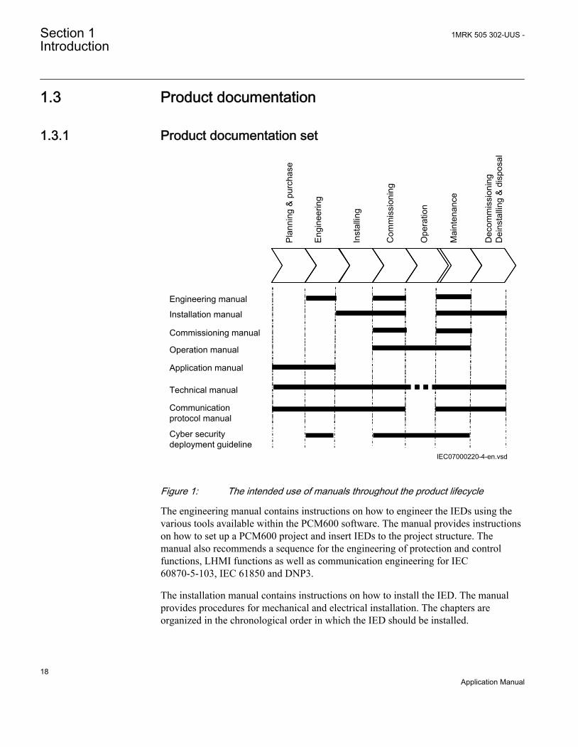
Figure 1: The intended use of manuals throughout the product lifecycle
The engineering manual contains instructions on how to engineer the IEDs using thevarious tools available within the PCM600 software. The manual provides instructionson how to set up a PCM600 project and insert IEDs to the project structure. Themanual also recommends a sequence for the engineering of protection and controlfunctions, LHMI functions as well as communication engineering for IEC60870-5-103, IEC 61850 and DNP3.
The installation manual contains instructions on how to install the IED. The manualprovides procedures for mechanical and electrical installation. The chapters areorganized in the chronological order in which the IED should be installed.
Section 1 1MRK 505 302-UUS -Introduction
18Application Manual
The commissioning manual contains instructions on how to commission the IED. Themanual can also be used by system engineers and maintenance personnel for assistanceduring the testing phase. The manual provides procedures for the checking of externalcircuitry and energizing the IED, parameter setting and configuration as well asverifying settings by secondary injection. The manual describes the process of testingan IED in a substation which is not in service. The chapters are organized in thechronological order in which the IED should be commissioned. The relevantprocedures may be followed also during the service and maintenance activities.
The operation manual contains instructions on how to operate the IED once it has beencommissioned. The manual provides instructions for the monitoring, controlling andsetting of the IED. The manual also describes how to identify disturbances and how toview calculated and measured power grid data to determine the cause of a fault.
The application manual contains application descriptions and setting guidelines sortedper function. The manual can be used to find out when and for what purpose a typicalprotection function can be used. The manual can also provide assistance for calculatingsettings.
The technical manual contains application and functionality descriptions and listsfunction blocks, logic diagrams, input and output signals, setting parameters andtechnical data, sorted per function. The manual can be used as a technical referenceduring the engineering phase, installation and commissioning phase, and during normalservice.
The communication protocol manual describes the communication protocols supportedby the IED. The manual concentrates on the vendor-specific implementations.
The point list manual describes the outlook and properties of the data points specific tothe IED. The manual should be used in conjunction with the correspondingcommunication protocol manual.
The cyber security deployment guideline describes the process for handling cybersecurity when communicating with the IED. Certification, Authorization with rolebased access control, and product engineering for cyber security related events aredescribed and sorted by function. The guideline can be used as a technical referenceduring the engineering phase, installation and commissioning phase, and during normalservice.
1.3.2 Document revision historyDocument revision/date History-/May 2014 First release
1MRK 505 302-UUS - Section 1Introduction
19Application Manual

1.3.3 Related documentsDocuments related to REB670 Identify numberApplication manual 1MRK 505 302-UUS
Commissioning manual 1MRK 505 304-UUS
Product guide 1MRK 505 305-BUS
Technical manual 1MRK 505 303-UUS
Type test certificate 1MRK 505 305-TUS
670 series manuals Identify numberOperation manual 1MRK 500 118-UUS
Engineering manual 1MRK 511 308-UUS
Installation manual 1MRK 514 019-UUS
Communication protocol manual, DNP3 1MRK 511 301-UUS
Communication protocol manual, IEC 61850Edition 2
1MRK 511 303-UUS
Accessories guide 1MRK 514 012-BUS
Connection and Installation components 1MRK 513 003-BEN
Test system, COMBITEST 1MRK 512 001-BEN
1.4 Document symbols and conventions
1.4.1 Symbols
The electrical warning icon indicates the presence of a hazard whichcould result in electrical shock.
The warning icon indicates the presence of a hazard which could resultin personal injury.
The caution hot surface icon indicates important information orwarning about the temperature of product surfaces.
Section 1 1MRK 505 302-UUS -Introduction
20Application Manual

The caution icon indicates important information or warning related tothe concept discussed in the text. It might indicate the presence of ahazard which could result in corruption of software or damage toequipment or property.
The information icon alerts the reader of important facts and conditions.
The tip icon indicates advice on, for example, how to design yourproject or how to use a certain function.
Although warning hazards are related to personal injury, it is necessary to understandthat under certain operational conditions, operation of damaged equipment may resultin degraded process performance leading to personal injury or death. It is importantthat the user fully complies with all warning and cautionary notices.
1.4.2 Document conventions• Abbreviations and acronyms in this manual are spelled out in the glossary. The
glossary also contains definitions of important terms.• Push button navigation in the LHMI menu structure is presented by using the push
button icons.For example, to navigate between the options, use and .
• HMI menu paths are presented in bold.For example, select Main menu/Settings.
• LHMI messages are shown in Courier font.For example, to save the changes in non-volatile memory, select Yes and press
.• Parameter names are shown in italics.
For example, the function can be enabled and disabled with the Operation setting.• Each function block symbol shows the available input/output signal.
• the character ^ in front of an input/output signal name indicates that thesignal name may be customized using the PCM600 software.
• the character * after an input/output signal name indicates that the signalmust be connected to another function block in the application configurationto achieve a valid application configuration.
• Logic diagrams describe the signal logic inside the function block and arebordered by dashed lines.
1MRK 505 302-UUS - Section 1Introduction
21Application Manual
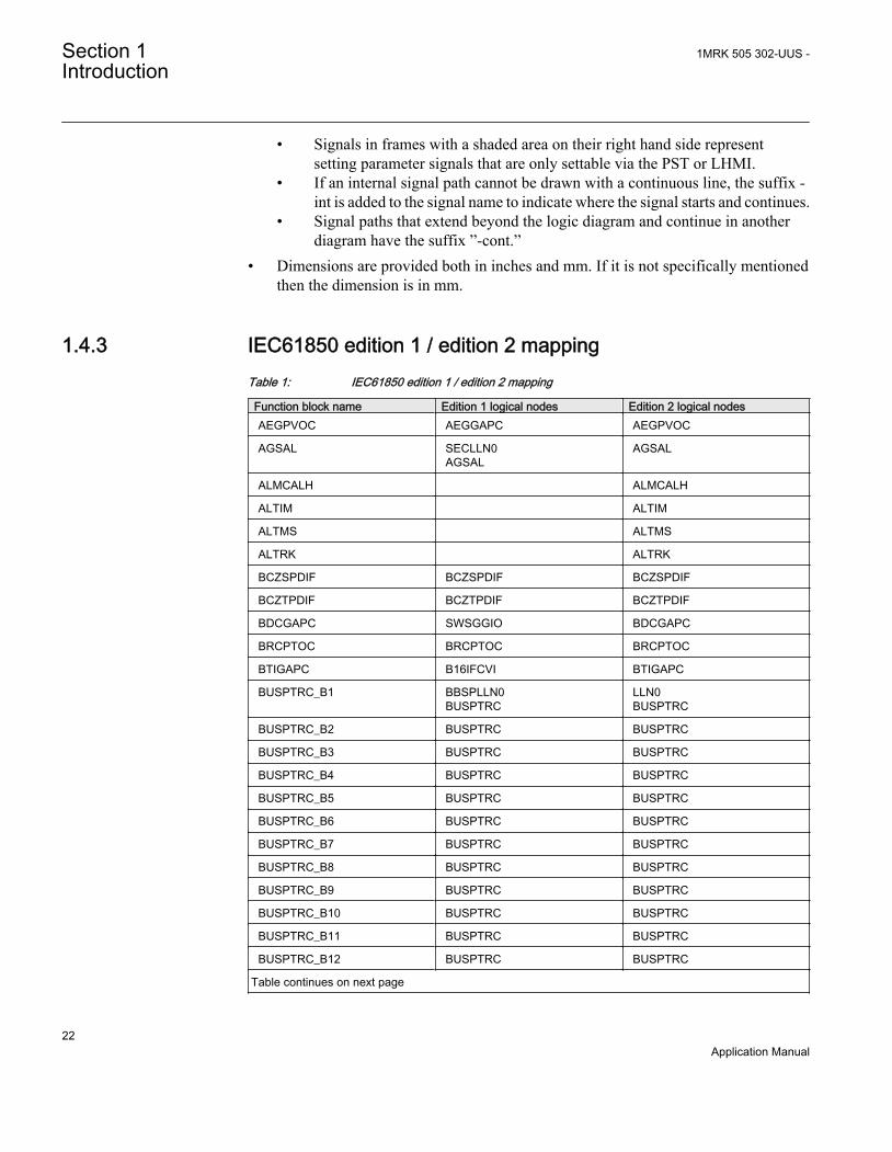
• Signals in frames with a shaded area on their right hand side representsetting parameter signals that are only settable via the PST or LHMI.
• If an internal signal path cannot be drawn with a continuous line, the suffix -int is added to the signal name to indicate where the signal starts and continues.
• Signal paths that extend beyond the logic diagram and continue in anotherdiagram have the suffix ”-cont.”
• Dimensions are provided both in inches and mm. If it is not specifically mentionedthen the dimension is in mm.
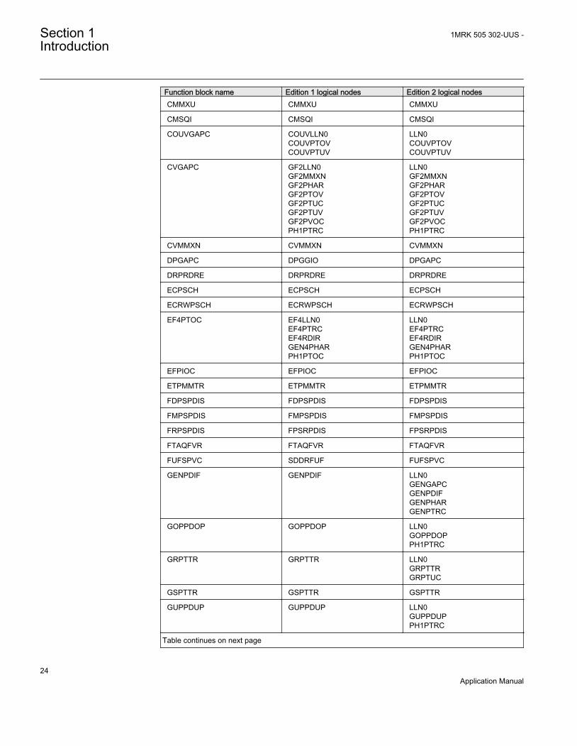
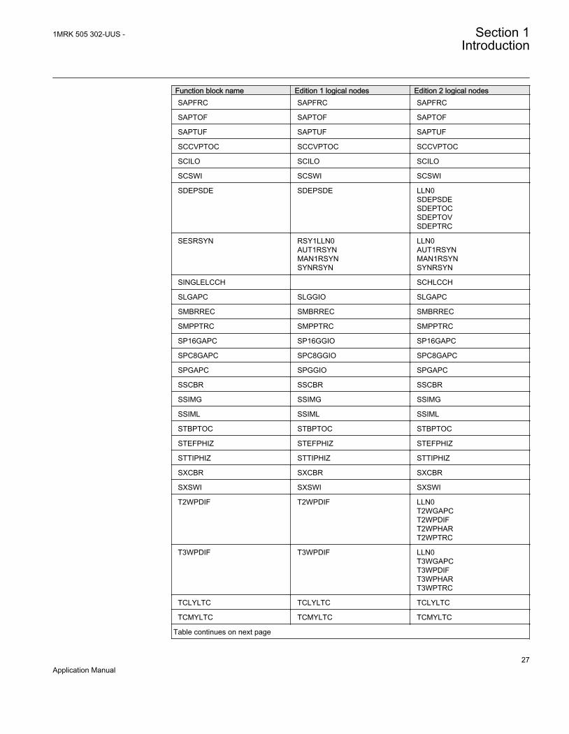
1.4.3 IEC61850 edition 1 / edition 2 mappingTable 1: IEC61850 edition 1 / edition 2 mapping
Function block name Edition 1 logical nodes Edition 2 logical nodesAEGPVOC AEGGAPC AEGPVOC
AGSAL SECLLN0AGSAL
AGSAL
ALMCALH ALMCALH
ALTIM ALTIM
ALTMS ALTMS
ALTRK ALTRK
BCZSPDIF BCZSPDIF BCZSPDIF
BCZTPDIF BCZTPDIF BCZTPDIF
BDCGAPC SWSGGIO BDCGAPC
BRCPTOC BRCPTOC BRCPTOC
BTIGAPC B16IFCVI BTIGAPC
BUSPTRC_B1 BBSPLLN0BUSPTRC
LLN0BUSPTRC
BUSPTRC_B2 BUSPTRC BUSPTRC
BUSPTRC_B3 BUSPTRC BUSPTRC
BUSPTRC_B4 BUSPTRC BUSPTRC
BUSPTRC_B5 BUSPTRC BUSPTRC
BUSPTRC_B6 BUSPTRC BUSPTRC
BUSPTRC_B7 BUSPTRC BUSPTRC
BUSPTRC_B8 BUSPTRC BUSPTRC
BUSPTRC_B9 BUSPTRC BUSPTRC
BUSPTRC_B10 BUSPTRC BUSPTRC
BUSPTRC_B11 BUSPTRC BUSPTRC
BUSPTRC_B12 BUSPTRC BUSPTRC
Table continues on next page
Section 1 1MRK 505 302-UUS -Introduction
22Application Manual

Function block name Edition 1 logical nodes Edition 2 logical nodesBUSPTRC_B13 BUSPTRC BUSPTRC
BUSPTRC_B14 BUSPTRC BUSPTRC
BUSPTRC_B15 BUSPTRC BUSPTRC
BUSPTRC_B16 BUSPTRC BUSPTRC
BUSPTRC_B17 BUSPTRC BUSPTRC
BUSPTRC_B18 BUSPTRC BUSPTRC
BUSPTRC_B19 BUSPTRC BUSPTRC
BUSPTRC_B20 BUSPTRC BUSPTRC
BUSPTRC_B21 BUSPTRC BUSPTRC
BUSPTRC_B22 BUSPTRC BUSPTRC
BUSPTRC_B23 BUSPTRC BUSPTRC
BUSPTRC_B24 BUSPTRC BUSPTRC
BUTPTRC_B1 BBTPLLN0BUTPTRC
LLN0BUTPTRC
BUTPTRC_B2 BUTPTRC BUTPTRC
BUTPTRC_B3 BUTPTRC BUTPTRC
BUTPTRC_B4 BUTPTRC BUTPTRC
BUTPTRC_B5 BUTPTRC BUTPTRC
BUTPTRC_B6 BUTPTRC BUTPTRC
BUTPTRC_B7 BUTPTRC BUTPTRC
BUTPTRC_B8 BUTPTRC BUTPTRC
BZNSPDIF_A BZNSPDIF BZNSGAPCBZNSPDIF
BZNSPDIF_B BZNSPDIF BZNSGAPCBZNSPDIF
BZNTPDIF_A BZNTPDIF BZNTGAPCBZNTPDIF
BZNTPDIF_B BZNTPDIF BZNTGAPCBZNTPDIF
CBPGAPC CBPLLN0CBPMMXUCBPPTRCHOLPTOVHPH1PTOVPH3PTOCPH3PTUCRP3PDOP
LLN0CBPPTRCHOLPTOVHPH1PTOVPH3PTOCPH3PTUCRP3PDOP
CCPDSC CCRPLD CCPDSC
CCRBRF CCRBRF CCRBRF
CCSRBRF CCSRBRF CCSRBRF
CCSSPVC CCSRDIF CCSSPVC
Table continues on next page
1MRK 505 302-UUS - Section 1Introduction
23Application Manual
Function block name Edition 1 logical nodes Edition 2 logical nodesCMMXU CMMXU CMMXU
CMSQI CMSQI CMSQI
COUVGAPC COUVLLN0COUVPTOVCOUVPTUV
LLN0COUVPTOVCOUVPTUV
CVGAPC GF2LLN0GF2MMXNGF2PHARGF2PTOVGF2PTUCGF2PTUVGF2PVOCPH1PTRC
LLN0GF2MMXNGF2PHARGF2PTOVGF2PTUCGF2PTUVGF2PVOCPH1PTRC
CVMMXN CVMMXN CVMMXN
DPGAPC DPGGIO DPGAPC
DRPRDRE DRPRDRE DRPRDRE
ECPSCH ECPSCH ECPSCH
ECRWPSCH ECRWPSCH ECRWPSCH
EF4PTOC EF4LLN0EF4PTRCEF4RDIRGEN4PHARPH1PTOC
LLN0EF4PTRCEF4RDIRGEN4PHARPH1PTOC
EFPIOC EFPIOC EFPIOC
ETPMMTR ETPMMTR ETPMMTR
FDPSPDIS FDPSPDIS FDPSPDIS
FMPSPDIS FMPSPDIS FMPSPDIS
FRPSPDIS FPSRPDIS FPSRPDIS
FTAQFVR FTAQFVR FTAQFVR
FUFSPVC SDDRFUF FUFSPVC
GENPDIF GENPDIF LLN0GENGAPCGENPDIFGENPHARGENPTRC
GOPPDOP GOPPDOP LLN0GOPPDOPPH1PTRC
GRPTTR GRPTTR LLN0GRPTTRGRPTUC
GSPTTR GSPTTR GSPTTR
GUPPDUP GUPPDUP LLN0GUPPDUPPH1PTRC
Table continues on next page
Section 1 1MRK 505 302-UUS -Introduction
24Application Manual

Function block name Edition 1 logical nodes Edition 2 logical nodesHZPDIF HZPDIF HZPDIF
INDCALCH INDCALH
ITBGAPC IB16FCVB ITBGAPC
L3CPDIF L3CPDIF LLN0L3CGAPCL3CPDIFL3CPHARL3CPTRC
L4UFCNT L4UFCNT L4UFCNT
L6CPDIF L6CPDIF LLN0L6CGAPCL6CPDIFL6CPHARL6CPTRC
LAPPGAPC LAPPLLN0LAPPPDUPLAPPPUPF
LLN0LAPPPDUPLAPPPUPF
LCCRPTRC LCCRPTRC LCCRPTRC
LCNSPTOC LCNSPTOC LCNSPTOC
LCNSPTOV LCNSPTOV LCNSPTOV
LCP3PTOC LCP3PTOC LCP3PTOC
LCP3PTUC LCP3PTUC LCP3PTUC
LCPTTR LCPTTR LCPTTR
LCZSPTOC LCZSPTOC LCZSPTOC
LCZSPTOV LCZSPTOV LCZSPTOV
LD0LLN0 LLN0 LLN0
LDLPSCH LDLPDIF LDLPSCH
LDRGFC STSGGIO LDRGFC
LEXPDIS LEXPDIS LLN0LEXPDISLEXPTRC
LFPTTR LFPTTR LFPTTR
LMBRFLO LMBRFLO LMBRFLO
LOVPTUV LOVPTUV LOVPTUV
LPHD LPHD LPHD
LT3CPDIF LT3CPDIF LLN0LT3CGAPCLT3CPDIFLT3CPHARLT3CPTRC
Table continues on next page
1MRK 505 302-UUS - Section 1Introduction
25Application Manual

Function block name Edition 1 logical nodes Edition 2 logical nodesLT6CPDIF LT6CPDIF LLN0
LT6CGAPCLT6CPDIFLT6CPHARLT6CPTRC
MVGAPC MVGGIO MVGAPC
NS2PTOC NS2LLN0NS2PTOCNS2PTRC
LLN0NS2PTOCNS2PTRC
NS4PTOC EF4LLN0EF4PTRCEF4RDIRGEN4PHARPH1PTOC
LLN0EF4PTRCEF4RDIRPH1PTOC
OC4PTOC OC4LLN0GEN4PHARPH3PTOCPH3PTRC
LLN0GEN4PHARPH3PTOCPH3PTRC
OEXPVPH OEXPVPH OEXPVPH
OOSPPAM OOSPPAM LLN0OOSPPAMOOSPTRC
OV2PTOV GEN2LLN0OV2PTOVPH1PTRC
LLN0OV2PTOVPH1PTRC
PAPGAPC PAPGAPC PAPGAPC
PCFCNT PCGGIO PCFCNT
PH4SPTOC OCNDLLN0GEN4PHARPH1BPTOCPH1PTRC
LLN0GEN4PHARPH1BPTOCPH1PTRC
PHPIOC PHPIOC PHPIOC
PRPSTATUS RCHLCCH RCHLCCHSCHLCCH
PSLPSCH ZMRPSL PSLPSCH
PSPPPAM PSPPPAM LLN0PSPPPAMPSPPTRC
QCBAY QCBAY LLN0
QCRSV QCRSV QCRSV
REFPDIF REFPDIF REFPDIF
ROTIPHIZ ROTIPHIZ LLN0ROTIPHIZROTIPTRC
ROV2PTOV GEN2LLN0PH1PTRCROV2PTOV
LLN0PH1PTRCROV2PTOV
Table continues on next page
Section 1 1MRK 505 302-UUS -Introduction
26Application Manual
Function block name Edition 1 logical nodes Edition 2 logical nodesSAPFRC SAPFRC SAPFRC
SAPTOF SAPTOF SAPTOF
SAPTUF SAPTUF SAPTUF
SCCVPTOC SCCVPTOC SCCVPTOC
SCILO SCILO SCILO
SCSWI SCSWI SCSWI
SDEPSDE SDEPSDE LLN0SDEPSDESDEPTOCSDEPTOVSDEPTRC
SESRSYN RSY1LLN0AUT1RSYNMAN1RSYNSYNRSYN
LLN0AUT1RSYNMAN1RSYNSYNRSYN
SINGLELCCH SCHLCCH
SLGAPC SLGGIO SLGAPC
SMBRREC SMBRREC SMBRREC
SMPPTRC SMPPTRC SMPPTRC
SP16GAPC SP16GGIO SP16GAPC
SPC8GAPC SPC8GGIO SPC8GAPC
SPGAPC SPGGIO SPGAPC
SSCBR SSCBR SSCBR
SSIMG SSIMG SSIMG
SSIML SSIML SSIML
STBPTOC STBPTOC STBPTOC
STEFPHIZ STEFPHIZ STEFPHIZ
STTIPHIZ STTIPHIZ STTIPHIZ
SXCBR SXCBR SXCBR
SXSWI SXSWI SXSWI
T2WPDIF T2WPDIF LLN0T2WGAPCT2WPDIFT2WPHART2WPTRC
T3WPDIF T3WPDIF LLN0T3WGAPCT3WPDIFT3WPHART3WPTRC
TCLYLTC TCLYLTC TCLYLTC
TCMYLTC TCMYLTC TCMYLTC
Table continues on next page
1MRK 505 302-UUS - Section 1Introduction
27Application Manual

Function block name Edition 1 logical nodes Edition 2 logical nodesTEIGAPC TEIGGIO TEIGAPC
TMAGAPC TMAGGIO TMAGAPC
TR1ATCC TR1ATCC TR1ATCC
TR8ATCC TR8ATCC TR8ATCC
TRPTTR TRPTTR TRPTTR
UV2PTUV GEN2LLN0PH1PTRCUV2PTUV
LLN0PH1PTRCUV2PTUV
VDCPTOV VDCPTOV VDCPTOV
VDSPVC VDRFUF VDSPVC
VMMXU VMMXU VMMXU
VMSQI VMSQI VMSQI
VNMMXU VNMMXU VNMMXU
VRPVOC VRLLN0PH1PTRCPH1PTUVVRPVOC
LLN0PH1PTRCPH1PTUVVRPVOC
VSGAPC VSGGIO VSGAPC
WRNCALH WRNCALH
ZC1PPSCH ZPCPSCH ZPCPSCH
ZC1WPSCH ZPCWPSCH ZPCWPSCH
ZCLCPSCH ZCLCPLAL LLN0ZCLCPSCH
ZCPSCH ZCPSCH ZCPSCH
ZCRWPSCH ZCRWPSCH ZCRWPSCH
ZCVPSOF ZCVPSOF ZCVPSOF
ZGVPDIS ZGVLLN0PH1PTRCZGVPDISZGVPTUV
LLN0PH1PTRCZGVPDISZGVPTUV
ZMCAPDIS ZMCAPDIS ZMCAPDIS
ZMCPDIS ZMCPDIS ZMCPDIS
ZMFCPDIS ZMFCLLN0PSFPDISZMFPDIS
LLN0PSFPDISZMFPDIS
ZMFPDIS ZMFLLN0PSFPDISZMFPDIS
LLN0PSFPDISZMFPDIS
ZMHPDIS ZMHPDIS ZMHPDIS
ZMMAPDIS ZMMAPDIS ZMMAPDIS
ZMMPDIS ZMMPDIS ZMMPDIS
Table continues on next page
Section 1 1MRK 505 302-UUS -Introduction
28Application Manual

Function block name Edition 1 logical nodes Edition 2 logical nodesZMQAPDIS ZMQAPDIS ZMQAPDIS
ZMQPDIS ZMQPDIS ZMQPDIS
ZMRAPDIS ZMRAPDIS ZMRAPDIS
ZMRPDIS ZMRPDIS ZMRPDIS
ZMRPSB ZMRPSB ZMRPSB
ZSMGAPC ZSMGAPC ZSMGAPC
1MRK 505 302-UUS - Section 1Introduction
29Application Manual

30

Section 2 Application
2.1 General IED application
REB670 is designed for the selective, reliable and fast differential protection ofbusbars, T-connections and meshed corners. REB670 can be used for protection ofsingle and double busbar with or without transfer bus, double circuit breaker or breaker-and-a-half stations. The IED is applicable for the protection of medium voltage (MV),high voltage (HV) and extra high voltage (EHV) installations at a power systemfrequency of 50Hz or 60Hz. The IED can detect all types of internal phase-to-phaseand phase-to-ground faults in solidly grounded or low impedance grounded powersystems, as well as all internal multi-phase faults in isolated or high-impedancegrounded power systems.
Ordering of PT inputs inside of the busbar protection IED will allow integration ofvoltage related functionality like under-voltage release, residual over-voltage, powerfunctions, metering and voltage recording during the faults. However attention shall begiven to the fact that inclusion of PT inputs will reduce number of available CT inputs(in total 24 analogue inputs are the product limit). Consequently when PT inputs areordered the busbar protection IED will be applicable for buses with a fewer number ofbays. Practically the number of available CT inputs will limit the size of the stationwhich can be protected.
REB670 has very low requirements on the main current transformers (that is, CTs) andno interposing current transformers are necessary. For all applications, it is possible toinclude and mix main CTs with 1A and 5A rated secondary current within the sameprotection zone. Typically, CTs with up to 10:1 ratio difference can be used within thesame differential protection zone. Adjustment for different main CT ratios is achievednumerically by a parameter setting.
The numerical, low-impedance differential protection function is designed for fast andselective protection for faults within protected zone. All connected CT inputs areprovided with a restraint feature. The minimum pick-up value for the differentialcurrent is set to give a suitable sensitivity for all internal faults. For busbar protectionapplications typical setting value for the minimum differential operating current isfrom 50% to 150% of the biggest CT. This setting is made directly in primary amperes.The operating slope for the differential operating characteristic is fixed to 53% in thealgorithm.
1MRK 505 302-UUS - Section 2Application
31Application Manual

The fast tripping time (shortest trip time is 5ms) of the low-impedance differentialprotection function is especially advantageous for power system networks with highfault levels or where fast fault clearance is required for power system stability.
All CT inputs are provided with a restraint feature. The operation is based on the well-proven RADSS percentage restraint stabilization principle, with an extra stabilizationfeature to stabilize for very heavy CT saturation. Stability for external faults isguaranteed if a CT is not saturated for at least two milliseconds during each powersystem cycle.
The advanced open CT detection algorithm detects instantly the open CT secondarycircuits and prevents differential protection operation without any need for additionalcheck zone.
Differential protection zones in REB670 include a sensitive operational pickup. Thissensitive operational pickup is designed to be able to detect internal busbar groundfaults in low impedance grounded power systems (that is, power systems where theground-fault current is limited to a certain level, typically between 300A and 2000Aprimary by a neutral point reactor or resistor). Alternatively this sensitive pickup canbe used when high sensitivity is required from busbar differential protection (that is,energizing of the bus via long line).
Overall operating characteristic of the differential function in REB670 is shown infigure 2.
Differential protectionoperation characteristic
Operateregion
Diff Oper Level
I d [P
rimar
y Am
ps]
Iin [Primary Amps]
s=0.53
I d=I in
Sensitivedifferentialprotection
en06000142.vsd
Sensitive Oper Level Sens Iin Block
IEC06000142 V1 EN
Figure 2: REB670 operating characteristic
Section 2 1MRK 505 302-UUS -Application
32Application Manual
Integrated overall check zone feature, independent from any disconnector position, isavailable. It can be used in double busbar stations to secure stability of the busbardifferential protection in case of entirely wrong status indication of busbardisconnector in any of the feeder bays.
Flexible, software based dynamic Zone Selection enables easy and fast adaptation tothe most common substation arrangements such as single busbar with or withouttransfer bus, double busbar with or without transfer bus, breaker-and-a-half stations,double busbar-double breaker stations, ring busbars, and so on. The software baseddynamic Zone Selections ensures:
• Dynamic linking of measured CT currents to the appropriate differential protectionzone as required by substation topology
• Efficient merging of the two differential zones when required by substationtopology (that is load-transfer)
• Selective operation of busbar differential protection ensures tripping only ofcircuit breakers connected to the faulty zone
• Correct marshaling of backup-trip commands from internally integrated orexternal circuit breaker failure protections to all surrounding circuit breakers
• Easy incorporation of bus-section and/or bus-coupler bays (that is, tie-breakers)with one or two sets of CTs into the protection scheme
• Disconnector and/or circuit breaker status supervision
Advanced Zone Selection logic accompanied by optionally available end-fault and/orcircuit breaker failure protections ensure minimum possible tripping time andselectivity for faults within the blind spot or the end zone between bay CT and baycircuit breaker. Therefore REB670 offers best possible coverage for such faults infeeder and bus-section/bus-coupler bays.
Optionally available circuit breaker failure protection, one for every CT input intoREB670, offers secure local back-up protection for the circuit breakers in the station.
Optionally available four-stage, non-directional overcurrent protections, one for everyCT input into REB670, provide remote backup functionality for connected feeders andremote-end stations.
Optionally available voltage and frequency protection functions open possibility toinclude voltage release criterion for busbar protection or to integrate independent over-,under-voltage protection for the bus in the busbar protection IED.
Optionally available over-current, thermal overload and capacitor bank protectionfunctions open possibilities to integrate protection of shunt reactors and shunt capacitorbanks into the busbar protection IED.
1MRK 505 302-UUS - Section 2Application
33Application Manual
It is normal practice to have just one busbar protection IED per busbar. Neverthelesssome utilities do apply two independent busbar protection IEDs per zone of protection.REB670 IED fits both solutions.
A simplified bus differential protection for multi-phase faults and ground faults can beobtained by using a single, one-phase REB670 IED with external auxiliary summationcurrent transformers.
Optional apparatus control for up to 30 objects can provide a facility to draw simplifiedsingle line diagram (SLD) of the station on the local HMI.
Note that customized REB670 is delivered without any configuration.Thus the complete IED engineering shall be done by the customer or itssystem integrator. In order to secure proper operation of the busbarprotection it is strictly recommended to always start engineering workfrom the PCM600 project for the pre-configured REB670 which is theclosest to the actual application. Then, necessary modifications shall beapplied in order to adopt the customized IED configuration to suite theactual station layout. The PCM600 project for the pre-configuredREB670 IEDs is available in the Connectivity Package DVD.
2.2 Main protection functions
2 = number of basic instances0-3 = option quantities3-A03
= optional function included in packages A03 (refer to ordering details)
Section 2 1MRK 505 302-UUS -Application
34Application Manual

IEC 61850 ANSI Function description Busbar Busbar
REB670
REB
670
(A31
A)
Differential protection
BUTPTRC,BCZTPDIF,BZNTPDIF,BZITGGIO,BUTSM4
87B Busbar differential protection, 2 zones, three phase/4bays
BUTPTRC,BCZTPDIF,BZNTPDIF,BZITGGIO,BUTSM8
87B Busbar differential protection, 2 zones, three phase/8bays
1 1
BUSPTRC,BCZSPDIF,BZNSPDIF,BZISGGIO,BUSSM12
87B Busbar differential protection, 2 zones, single phase/12bays
BUSPTRC,BCZSPDIF,BZNSPDIF,BZISGGIO,BUSSM24
87B Busbar differential protection, 2 zones, single phase/24bays
1
BDCGAPC Status of primary switching object for busbar protectionzone selection
96 40
2.3 Back-up protection functions
IEC 61850 ANSI Function description Busbar Busbar
REB670
REB
670
(A31
A)
Current protection
OC4PTOC 51_671) Four step phase overcurrent protection 0-8 8-C07
PH4SPTOC 51 Four step single phase overcurrent protection 0-24
EF4PTOC 51N67N2)
Four step residual overcurrent protection 0-8
NS4PTOC 46I2 Four step directional negative phase sequenceovercurrent protection
0–8
TRPTTR 49 Thermal overload protection, two time constant 0-2
Table continues on next page
1MRK 505 302-UUS - Section 2Application
35Application Manual

IEC 61850 ANSI Function description Busbar Busbar
REB670
REB
670
(A31
A)
CCRBRF 50BF Breaker failure protection 0-8 8-C11
CCSRBRF 50BF Breaker failure protection, single phase version 0-24
GUPPDUP 37 Directional underpower protection 0-4
GOPPDOP 32 Directional overpower protection 0-4
CBPGAPC Capacitor bank protection 0-2
Voltage protection
UV2PTUV 27 Two step undervoltage protection 0-2
OV2PTOV 59 Two step overvoltage protection 0-2
ROV2PTOV 59N Two step residual overvoltage protection 0-2
VDCPTOV 60 Voltage differential protection 0-2
LOVPTUV 27 Loss of voltage check 0-2
Frequency protection
SAPTUF 81 Underfrequency protection 0-6
SAPTOF 81 Overfrequency protection 0-6
SAPFRC 81 Rate-of-change frequency protection 0-6
Multipurpose protection
CVGAPC General current and voltage protection 0-6
1) 67 requires voltage2) 67N requires voltage
2.4 Control and monitoring functions
IEC 61850 ANSI Function description Busbar Busbar
REB670
REB
670
(A31
A)
Control
SESRSYN 25 Synchrocheck, energizing check and synchronizing 0-3
SMBRREC 79 Autorecloser 0-2 2-H05
Table continues on next page
Section 2 1MRK 505 302-UUS -Application
36Application Manual
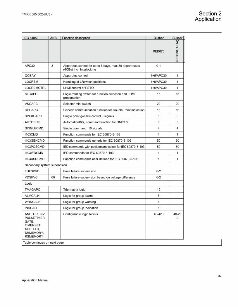
IEC 61850 ANSI Function description Busbar Busbar
REB670
REB
670
(A31
A)
APC30 3 Apparatus control for up to 6 bays, max 30 apparatuses(6CBs) incl. interlocking
0-1
QCBAY Apparatus control 1+5/APC30 1
LOCREM Handling of LRswitch positions 1+5/APC30 1
LOCREMCTRL LHMI control of PSTO 1+5/APC30 1
SLGAPC Logic rotating switch for function selection and LHMIpresentation
15 15
VSGAPC Selector mini switch 20 20
DPGAPC Generic communication function for Double Point indication 16 16
SPC8GAPC Single point generic control 8 signals 5 5
AUTOBITS AutomationBits, command function for DNP3.0 3 3
SINGLECMD Single command, 16 signals 4 4
I103CMD Function commands for IEC 60870-5-103 1 1
I103GENCMD Function commands generic for IEC 60870-5-103 50 50
I103POSCMD IED commands with position and select for IEC 60870-5-103 50 50
I103IEDCMD IED commands for IEC 60870-5-103 1 1
I103USRCMD Function commands user defined for IEC 60870-5-103 1 1
Secondary system supervision
FUFSPVC Fuse failure supervision 0-2
VDSPVC 60 Fuse failure supervision based on voltage difference 0-2
Logic
TMAGAPC Trip matrix logic 12
ALMCALH Logic for group alarm 5
WRNCALH Logic for group warning 5
INDCALH Logic for group indication 5
AND, OR, INV,PULSETIMER,GATE,TIMERSET,XOR, LLD,SRMEMORY,RSMEMORY
Configurable logic blocks 40-420 40-280
Table continues on next page
1MRK 505 302-UUS - Section 2Application
37Application Manual
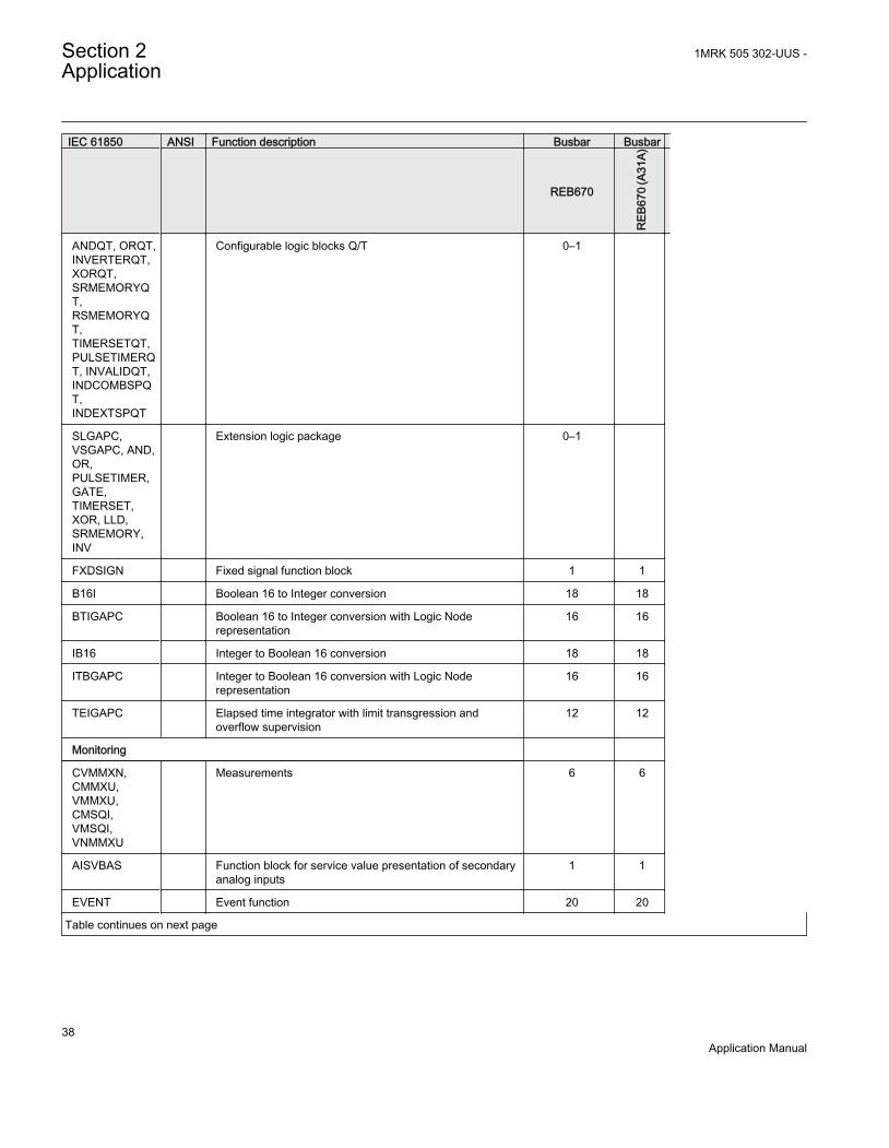
IEC 61850 ANSI Function description Busbar Busbar
REB670
REB
670
(A31
A)
ANDQT, ORQT,INVERTERQT,XORQT,SRMEMORYQT,RSMEMORYQT,TIMERSETQT,PULSETIMERQT, INVALIDQT,INDCOMBSPQT,INDEXTSPQT
Configurable logic blocks Q/T 0–1
SLGAPC,VSGAPC, AND,OR,PULSETIMER,GATE,TIMERSET,XOR, LLD,SRMEMORY,INV
Extension logic package 0–1
FXDSIGN Fixed signal function block 1 1
B16I Boolean 16 to Integer conversion 18 18
BTIGAPC Boolean 16 to Integer conversion with Logic Noderepresentation
16 16
IB16 Integer to Boolean 16 conversion 18 18
ITBGAPC Integer to Boolean 16 conversion with Logic Noderepresentation
16 16
TEIGAPC Elapsed time integrator with limit transgression andoverflow supervision
12 12
Monitoring
CVMMXN,CMMXU,VMMXU,CMSQI,VMSQI,VNMMXU
Measurements 6 6
AISVBAS Function block for service value presentation of secondaryanalog inputs
1 1
EVENT Event function 20 20
Table continues on next page
Section 2 1MRK 505 302-UUS -Application
38Application Manual

IEC 61850 ANSI Function description Busbar Busbar
REB670
REB
670
(A31
A)
DRPRDRE,A1RADR,A2RADR,A3RADR,A4RADR,B1RBDR,B2RBDR,B3RBDR,B4RBDR,B5RBDR,B6RBDR
Disturbance report 1 1
SPGAPC Generic communication function for Single Point indication 64 64
SP16GAPC Generic communication function for Single Point indication16 inputs
16 16
MVGAPC Generic communication function for Measured Value 24 24
BINSTATREP Logical signal status report 3 3
RANGE_XP Measured value expander block 28 28
SSIMG 63 Gas medium supervision 21 21
SSIML 71 Liquid medium supervision 3 3
SSCBR Circuit breaker monitoring 0-8 24-M14
I103MEAS Measurands for IEC 60870-5-103 1 1
I103MEASUSR Measurands user defined signals for IEC 60870-5-103 3 3
I103AR Function status auto-recloser for IEC 60870-5-103 1 1
I103EF Function status earth-fault for IEC 60870-5-103 1 1
I103FLTPROT Function status fault protection for IEC 60870-5-103 1 1
I103IED IED status for IEC 60870-5-103 1 1
I103SUPERV Supervison status for IEC 60870-5-103 1 1
I103USRDEF Status for user defiend signals for IEC 60870-5-103 20 20
L4UFCNT Event counter with limit supervision 30 30
Metering
PCFCNT Pulse-counter logic 16
ETPMMTR Function for energy calculation and demand handling 6
1MRK 505 302-UUS - Section 2Application
39Application Manual

2.5 Communication
IEC 61850 ANSI Function description Busbar Busbar
REB670
REB
670
(A31
A)
Station communication
LONSPA, SPA SPA communication protocol 1 1
ADE LON communication protocol 1 1
HORZCOMM Network variables via LON 1 1
PROTOCOL Operation selection between SPA and IEC60870-5-103 for SLM
1 1
RS485PROT Operation selection for RS485 1 1
RS485GEN RS485 1 1
DNPGEN DNP3.0 communication general protocol 1 1
DNPGENTCP DNP3.0 communication general TCP protocol 1 1
CHSERRS485
DNP3.0 for EIA-485 communication protocol 1 1
CH1TCP,CH2TCP,CH3TCP,CH4TCP
DNP3.0 for TCP/IP communication protocol 1 1
CHSEROPT DNP3.0 for TCP/IP and EIA-485 communicationprotocol
1 1
MST1TCP,MST2TCP,MST3TCP,MST4TCP
DNP3.0 for serial communication protocol 1 1
DNPFREC DNP3.0 fault records for TCP/IP and EIA-485communication protocol
1 1
IEC61850-8-1 Parameter setting function for IEC 61850 1 1
GOOSEINTLKRCV
Horizontal communication via GOOSE for interlocking 59 59
GOOSEBINRCV
Goose binary receive 16 16
GOOSEDPRCV
GOOSE function block to receive a double point value 64 64
GOOSEINTRCV
GOOSE function block to receive an integer value 32 32
GOOSEMVRCV
GOOSE function block to receive a measurand value 60 60
Table continues on next page
Section 2 1MRK 505 302-UUS -Application
40Application Manual

IEC 61850 ANSI Function description Busbar Busbar
REB670
REB
670
(A31
A)
GOOSESPRCV
GOOSE function block to receive a single point value 64 64
MULTICMDRCV,MULTICMDSND
Multiple command and transmit 60/10 60/10
FRONT,LANABI,LANAB,LANCDI,LANCD
Ethernet configuration of links 1 1
GATEWAY Ethernet configuration of link one 1 1
OPTICAL103 IEC 60870-5-103 Optical serial communication 1 1
RS485103 IEC 60870-5-103 serial communication for RS485 1 1
AGSAL Generic security application component 1 1
LD0LLN0 IEC 61850 LD0 LLN0 1 1
SYSLLN0 IEC 61850 SYS LLN0 1 1
LPHD Physical device information 1 1
PCMACCS IED Configuration Protocol 1 1
SECALARM Component for mapping security events on protocolssuch as DNP3 and IEC103
1 1
FSTACCS Field service tool access via SPA protocol overethernet communication
1 1
ACTIVLOG Activity logging parameters 1 1
ALTRK Service Tracking 1 1
SINGLELCCH Single ethernet port link status 1 1
PRPSTATUS Dual ethernet port link status 1 1
PRP IEC 62439-3 parallel redundancy protocol 0-1 1-P03
Remote communication
Binary signal transfer receive/transmit 6/36 6/36
Transmission of analog data from LDCM 1 1
Receive binary status from remote LDCM 6/3/3 6/3/3
1MRK 505 302-UUS - Section 2Application
41Application Manual

2.6 Basic IED functions
Table 2: Basic IED functions
IEC 61850 or functionname
Description
INTERRSIG Self supervision with internal event list
SELFSUPEVLST Self supervision with internal event list
TIMESYNCHGEN Time synchronization module
SYNCHBIN,SYNCHCAN,SYNCHCMPPS,SYNCHLON,SYNCHPPH,SYNCHPPS,SYNCHSNTP,SYNCHSPA,SYNCHCMPPS
Time synchronization
TIMEZONE Time synchronization
DSTBEGIN,DSTENABLE, DSTEND
GPS time synchronization module
IRIG-B Time synchronization
SETGRPS Number of setting groups
ACTVGRP Parameter setting groups
TESTMODE Test mode functionality
CHNGLCK Change lock function
SMBI Signal matrix for binary inputs
SMBO Signal matrix for binary outputs
SMMI Signal matrix for mA inputs
SMAI1 - SMAI20 Signal matrix for analog inputs
3PHSUM Summation block 3 phase
ATHSTAT Authority status
ATHCHCK Authority check
AUTHMAN Authority management
FTPACCS FTP access with password
SPACOMMMAP SPA communication mapping
SPATD Date and time via SPA protocol
DOSFRNT Denial of service, frame rate control for front port
DOSLANAB Denial of service, frame rate control for OEM port AB
DOSLANCD Denial of service, frame rate control for OEM port CD
DOSSCKT Denial of service, socket flow control
Table continues on next page
Section 2 1MRK 505 302-UUS -Application
42Application Manual
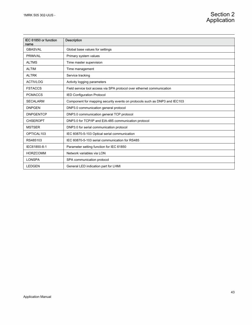
IEC 61850 or functionname
Description
GBASVAL Global base values for settings
PRIMVAL Primary system values
ALTMS Time master supervision
ALTIM Time management
ALTRK Service tracking
ACTIVLOG Activity logging parameters
FSTACCS Field service tool access via SPA protocol over ethernet communication
PCMACCS IED Configuration Protocol
SECALARM Component for mapping security events on protocols such as DNP3 and IEC103
DNPGEN DNP3.0 communication general protocol
DNPGENTCP DNP3.0 communication general TCP protocol
CHSEROPT DNP3.0 for TCP/IP and EIA-485 communication protocol
MSTSER DNP3.0 for serial communication protocol
OPTICAL103 IEC 60870-5-103 Optical serial communication
RS485103 IEC 60870-5-103 serial communication for RS485
IEC61850-8-1 Parameter setting function for IEC 61850
HORZCOMM Network variables via LON
LONSPA SPA communication protocol
LEDGEN General LED indication part for LHMI
1MRK 505 302-UUS - Section 2Application
43Application Manual

44

Section 3 Configuration
3.1 Description of configuration REB670
3.1.1 Available ACT configurations for pre-configured REB670Three configurations have been made available for pre-configured REB670 IED. Itshall be noted that all three configurations include the following features:
• fully configured for the total available number of bays in each REB670 variant• facility to take any bay out of service via the local HMI or externally via binary input• facility to block any of the two zones via the local HMI or externally via binary input• facility to block all bay trips via the local HMI or externally via binary input, but
leaving all other function in service (that is BBP Zones, BFP and OCP whereapplicable)
• facility to externally initiate built-in disturbance recorder• facility to connect external breaker failure backup trip signal from every bay• facility to connect external bay trip signal
3.1.2 Configuration X01This configuration includes only busbar protection for simple stations layouts (in otherwords, breaker-and-a-half, double breaker or single breaker stations). Additionally itcan be used for double busbar-single breaker stations where disconnector replica isdone by using only b auxiliary contact from every disconnector and/or circuit breakers.As a consequence no disconnector/breaker supervision will be available. It is as wellpossible to adapt this configuration by the signal matrix tool to be used as directreplacement of RED521 terminals. This configuration is available for all five REB670variants (that is A20, A31, B20, B21 & B31). It shall be noted that optional functionsbreaker failure protection CCRBRF (50BF), end fault protection and overcurrentprotection PH4SPTOC (51) can be ordered together with this configuration, but theywill not be pre-configured. Thus these optional functions shall be configured by theend user.
3.1.3 Configuration X02This configuration includes only busbar protection for double busbar-single breakerstations, where Zone Selection is done by using a and b auxiliary contacts from every
1MRK 505 302-UUS - Section 3Configuration
45Application Manual
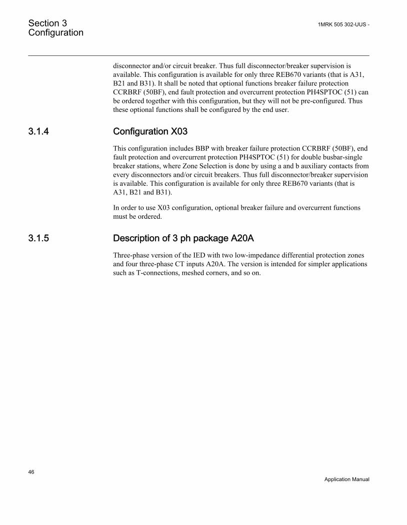
disconnector and/or circuit breaker. Thus full disconnector/breaker supervision isavailable. This configuration is available for only three REB670 variants (that is A31,B21 and B31). It shall be noted that optional functions breaker failure protectionCCRBRF (50BF), end fault protection and overcurrent protection PH4SPTOC (51) canbe ordered together with this configuration, but they will not be pre-configured. Thusthese optional functions shall be configured by the end user.
3.1.4 Configuration X03This configuration includes BBP with breaker failure protection CCRBRF (50BF), endfault protection and overcurrent protection PH4SPTOC (51) for double busbar-singlebreaker stations, where Zone Selection is done by using a and b auxiliary contacts fromevery disconnectors and/or circuit breakers. Thus full disconnector/breaker supervisionis available. This configuration is available for only three REB670 variants (that isA31, B21 and B31).
In order to use X03 configuration, optional breaker failure and overcurrent functionsmust be ordered.
3.1.5 Description of 3 ph package A20AThree-phase version of the IED with two low-impedance differential protection zonesand four three-phase CT inputs A20A. The version is intended for simpler applicationssuch as T-connections, meshed corners, and so on.
Section 3 1MRK 505 302-UUS -Configuration
46Application Manual
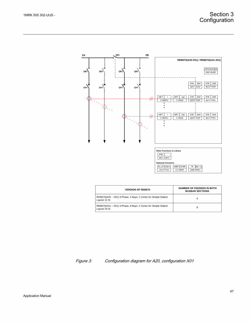
ZA ZB
REB670(A20-X01) / REB670(A31-X01)
QA1
QB1
QA1
QB1
Optional Functions
VERSION OF REB670 NUMBER OF FEEDERS IN BOTH
BUSBAR SECTIONS
REB670(A20 – X01) 3-Phase, 4 Bays, 2 Zones for Simple Station
Layout 12 AI 4
REB670(A31 – X01) 3-Phase, 8 Bays, 2 Zones for Simple Station
Layout 24 AI 8
QA1
QB1
QA1
QB1
BZNT PDIF
87B 3Id/I
BUT PTRC
87B 3Id/I
BUT PTRC
87B 3Id/I
BZNT PDIF
87B 3Id/I
OC4 PTOC
51_67 4(3I>)
CC RBRF
50BF 3I>BF
SMB RREC
79 5(0→1)
BZIT GGIO
87B 3Id/I
BCZT PDIF
87B 3Id/I
Other Functions in Library
BDC GAPC
87B
QB1
DRP RDRE
DFR/SER DR
C MMXU
MET I
C MSQI
MET Isqi
C MMXU
MET I
C MSQI
MET Isqi
GUID-853490E3-9BD2-47E4-93DC-A25765A92AFF V2 EN
Figure 3: Configuration diagram for A20, configuration X01
1MRK 505 302-UUS - Section 3Configuration
47Application Manual

3.1.6 Description of 3 ph package A31AThree-phase version of the IED with two low-impedance differential protection zonesand eight three-phase CT inputs A31A. The version is intended for applications onsmaller busbars, with up to two zones and eight CT inputs.
REB670 ANSI(A20A-X00) / REB670 ANSI(A31A-X00)
AC LOGIC
AC LOGIC
BUT PTRC
87B 3Id/IBZNT PDIF
87B 3Id/I
BUT PTRC
87B 3Id/I
Optional Functions
OC4 PTOC
51_67 4(3I>)
CC RBRF
50BF 3I>BF
SMB RREC
79 5(0→1)
ZA ZB
HW LOGIC189 189 189 189
REB670 ANSI(A20A-X00) / REB670 ANSI(A31A-X00)
BUT PTRC
87B 3Id/I
BUT PTRC
87B 3Id/IBZNT PDIF
87B 3Id/I
Other Functions in Library
BDC GAPC
87B
152BKR
152BKR
152BKR
152BKR
152BKR189 189
BZIT GGIO
87B 3Id/I
BCZT PDIF
87B 3Id/I
C MMXU
MET I
DRP RDRE
DFR/SER DR
BZIT GGIO
87B 3Id/I
BCZT PDIF
87B 3Id/I
C MMXU
MET I
DRP RDRE
DFR/SER DR
VERSION OF REB670NUMBER OF FEDERS IN
BOTH BUSBAR SECTIONS
REB670 ANSI(A20A – X00) 3-Phase, 4 Bays, 2 Zones for
Simple Station Layout 12 AI 6*
REB670 ANSI(A31A – X00) 3-Phase, 8 Bays, 2 Zones for
Simple Station Layout 24 AI 14*
* With Just one CT in the Bus Section Bay
NUMBER OF REB670
REQUIRED BY THE SCHEME
2
2
GUID-5084E3E1-F0EE-457E-96AC-AB8AA3994ADA V1 EN
Figure 4: Configuration diagram for A31A, configuration X00
Section 3 1MRK 505 302-UUS -Configuration
48Application Manual

ZA ZB
REB670(A31-X01)
QA1
QB1
QA1
QB1
QA1
QB1
QA1
QB1HW LOGIC
AC LOGIC
VERSION OF REB670 NUMBER OF FEEDERS IN BOTH BUSBAR SECTIONS
REB670(A31 – X01) 3-Phase, 8 Bays, 2 Zones for Simple Station Layout 24 AI
7*
BUT PTRC
87B 3Id/I
BUT PTRC
87B 3Id/IBZNT PDIF
87B 3Id/I
BUT PTRC
87B 3Id/IBZNT PDIF
87B 3Id/I
Optional Functions
OC4 PTOC
51/67 3I>
CC RBRF
50BF 3I>BF
SMB RREC
79 0? 1
Other Functions in Library
SWS GGIO
* With Just one CT in the Bus Section Bay
QB1 QB2
QA1
BCZT PDIF
87B 3Id/I
BZIT GGIO
87B 3Id/I
C MMXU
MET I
DRP RDRE
DFR/SER DR
IEC13000219-1-en.vsd
GUID-B0D0854B-9CFF-4579-91AB-274BD7B0665A V1 EN
Figure 5: Configuration diagram for A31, configuration X01
1MRK 505 302-UUS - Section 3Configuration
49Application Manual

GUID-1264BCF9-F245-423C-B620-3D66F3292F41 V2 EN
Figure 6: Configuration diagram for A31, configuration X01_1
Section 3 1MRK 505 302-UUS -Configuration
50Application Manual
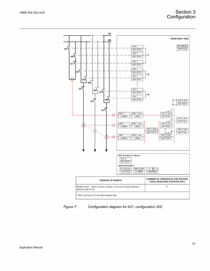
GUID-33AD6AD4-3315-4A4C-AB05-C1C04E815866 V2 EN
Figure 7: Configuration diagram for A31, configuration X02
1MRK 505 302-UUS - Section 3Configuration
51Application Manual
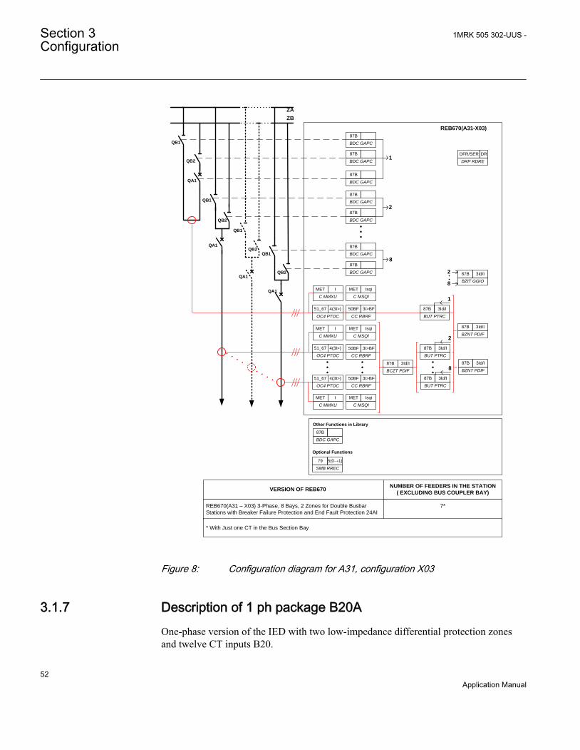
QB1
QB2
QA1
QB1
QB2
QA1
QB1
QB2
QA1
QB1
QB2
QA1
ZA
ZB
1
2
8
2
8
8
2
1
REB670(A31-X03)
Optional Functions
VERSION OF REB670NUMBER OF FEEDERS IN THE STATION
( EXCLUDING BUS COUPLER BAY)
REB670(A31 – X03) 3-Phase, 8 Bays, 2 Zones for Double Busbar
Stations with Breaker Failure Protection and End Fault Protection 24AI
7*
BZIT GGIO
87B 3Id/I
BDC GAPC
87B
BDC GAPC
87B
BDC GAPC
87B
BDC GAPC
87B
BDC GAPC
87B
BDC GAPC
87B
BDC GAPC
87B
BCZT PDIF
87B 3Id/I
BUT PTRC
87B 3Id/I
BUT PTRC
87B 3Id/I
BUT PTRC
87B 3Id/I
BZNT PDIF
87B 3Id/I
BZNT PDIF
87B 3Id/I
SMB RREC
79 5(0→1)
Other Functions in Library
BDC GAPC
87B
* With Just one CT in the Bus Section Bay
DRP RDRE
DFR/SER DR
C MSQI
MET Isqi
C MSQI
MET Isqi
CC RBRF
50BF 3I>BF
CC RBRF
50BF 3I>BF
CC RBRF
50BF 3I>BF
C MSQI
MET Isqi
OC4 PTOC
51_67 4(3I>)
OC4 PTOC
51_67 4(3I>)
OC4 PTOC
51_67 4(3I>)
C MMXU
MET I
C MMXU
MET I
C MMXU
MET I
GUID-223672EB-7E5B-410C-99F0-04B100FD2787 V2 EN
Figure 8: Configuration diagram for A31, configuration X03
3.1.7 Description of 1 ph package B20AOne-phase version of the IED with two low-impedance differential protection zonesand twelve CT inputs B20.
Section 3 1MRK 505 302-UUS -Configuration
52Application Manual

• Due to three available binary input modules, the B20A is intended for applicationswithout need for dynamic Zone Selection such as substations with single busbarwith or without bus-section breaker, breaker-and-a-half or double breakerarrangements. Three such IEDs offer cost effective solutions for such simplesubstation arrangements with up to twelve CT inputs.
• This version can be used with external auxiliary 3-phase to 1-phase summationcurrent transformers with different turns ratio for each phase.
REB670(B20-X01) / REB670(B21-X01) / REB670(B31-X01)PHASE L3
REB670(B20-X01) / REB670(B21-X01) / REB670(B31-X01)PHASE L2
ZA ZB
REB670(B20-X01) / REB670(B21-X01) / REB670(B31-X01)PHASE L1
QA1
QB1
QA1
QB1
Optional Functions
QA1
QB1
QA1
QB1
BUS PTRC
87B Id/IBZNS PDIF
87B Id/I
BZNS PDIF
87B Id/I
BUS PTRC
87B Id/I
PH4S PTOC
51 I>
CCS RBRF
50BF I>BF
SMB RREC
79 0? 1
BZIS GGIO
87B Id/I
BCZS PDIF
87B Id/I
Other Functions in Library
SWS GGIO
VERSION OF REB670 NUMBER OF FEDERS IN BOTH BUSBAR SECTIONS
REB670(B20 – X01) 1-Phase, 12 Bays, 2 Zones for Simple Station Layout 12 AI 12
REB670(B21 – X01) 1-Phase, 12 Bays, 2 Zones for Simple Station Layout 12 AI 12
NUMBER OF REB670 REQUIRED BY THE SCHEME
3
3
REB670(B31 – X01) 1-Phase, 24 Bays, 2 Zones for Simple Station Layout 24 AI 24 3
QB1
C MMXU
MET IDRP RDRE
DFR/SER DR
IEC13000223-1-en.vsd
GUID-FD09D683-B692-410F-A6EC-C501E72AEB14 V1 EN
Figure 9: Configuration diagram for B20, configuration X01
1MRK 505 302-UUS - Section 3Configuration
53Application Manual
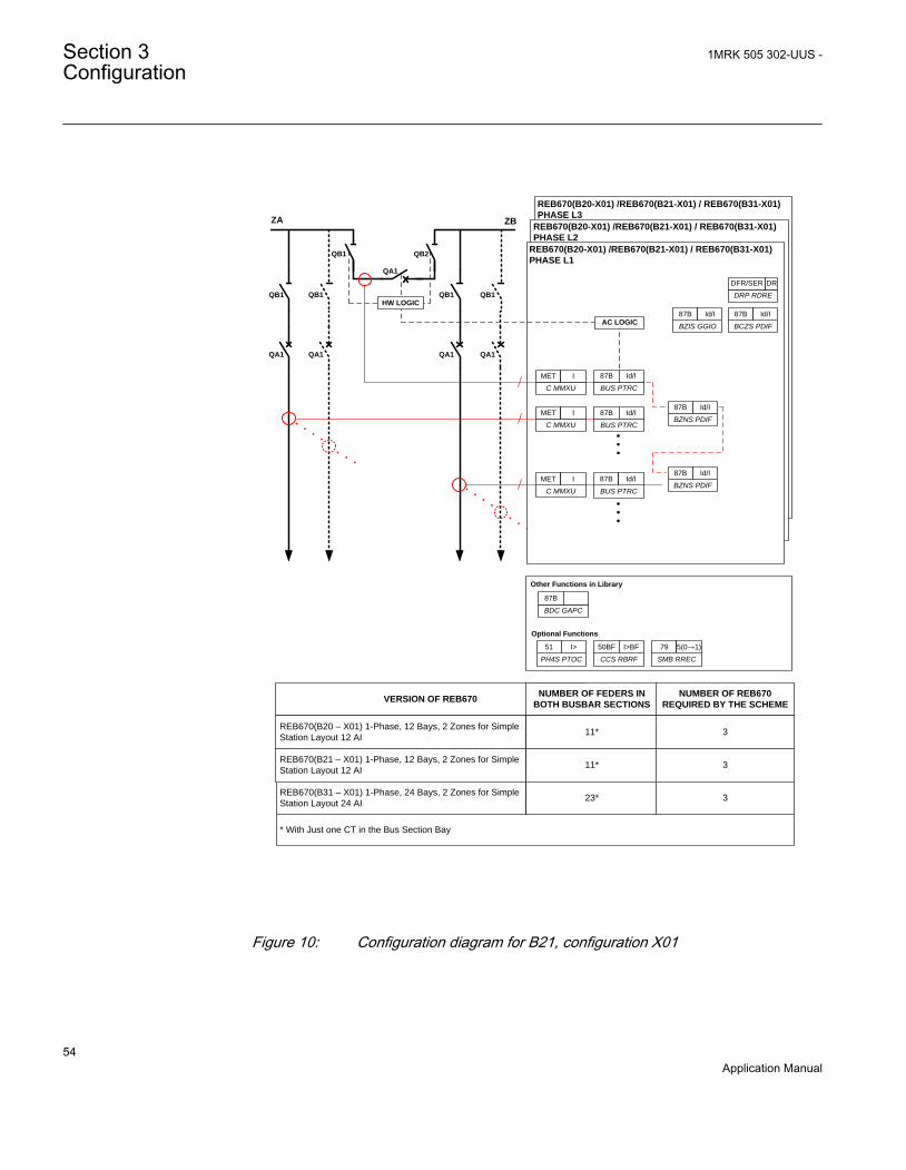
REB670(B20-X01) /REB670(B21-X01) / REB670(B31-X01)
PHASE L3
REB670(B20-X01) /REB670(B21-X01) / REB670(B31-X01)
PHASE L2
REB670(B20-X01) /REB670(B21-X01) / REB670(B31-X01)
PHASE L1
ZA ZB
QA1
QB1
QA1
QB1
QA1
QB1
QA1
QB1HW LOGIC
AC LOGIC
BUS PTRC
87B Id/I
BUS PTRC
87B Id/IBZNS PDIF
87B Id/I
BUS PTRC
87B Id/IBZNS PDIF
87B Id/I
QB1 QB2
QA1
BCZS PDIF
87B Id/I
BZIS GGIO
87B Id/I
C MMXU
MET I
DRP RDRE
DFR/SER DR
VERSION OF REB670NUMBER OF FEDERS IN
BOTH BUSBAR SECTIONS
REB670(B20 – X01) 1-Phase, 12 Bays, 2 Zones for Simple
Station Layout 12 AI 11*
REB670(B21 – X01) 1-Phase, 12 Bays, 2 Zones for Simple
Station Layout 12 AI 11*
* With Just one CT in the Bus Section Bay
NUMBER OF REB670
REQUIRED BY THE SCHEME
3
3
REB670(B31 – X01) 1-Phase, 24 Bays, 2 Zones for Simple
Station Layout 24 AI 23* 3
C MMXU
MET I
C MMXU
MET I
Optional Functions
PH4S PTOC
51 I>
CCS RBRF
50BF I>BF
SMB RREC
79 5(0→1)
Other Functions in Library
BDC GAPC
87B
GUID-7EF9DAD6-8ED2-4C77-8030-0A63AED769EC V2 EN
Figure 10: Configuration diagram for B21, configuration X01
Section 3 1MRK 505 302-UUS -Configuration
54Application Manual

3.1.8 Description of 1 ph package B31AOne-phase version of the IED with two low-impedance differential protection zonesand twenty-four CT inputs B31A.
• The IED is intended for busbar protection applications in big substations wheredynamic Zone Selection, quite large number of binary inputs and outputs andmany CT inputs are needed. The IED includes two differential zones and twenty-four CT inputs. Note that binary inputs can be shared between phases by includingthe LDCM communication module. This simplifies panel wiring and saves IOboards.
• This version can be used with external auxiliary 3-phase to 1-phase summationcurrent transformers with different turns ratio for each phase.
1MRK 505 302-UUS - Section 3Configuration
55Application Manual

REB670(B20-X01) / REB670(B21-X01) / REB670(B31-X01)PHASE L3
REB670(B20-X01) / REB670(B21-X01) / REB670(B31-X01)PHASE L2
REB670(B20-X01) / REB670(B21-X01) / REB670(B31-X01)PHASE L1
REB670(B20-X01) / REB670(B21-X01) / REB670(B31-X01)PHASE L3
REB670(B20-X01) / REB670(B21-X01) / REB670(B31-X01)PHASE L2
REB670(B20-X01) / REB670(B21-X01) / REB670(B31-X01)PHASE L1
ZA ZB
QA1
QB1
QA1
QB1
QA1
QB1
QA1
QB1HW LOGIC
AC LOGIC
AC LOGIC
BZNS PDIF
87B Id/I
BUS PTRC
87B Id/I
BZNS PDIF
87B Id/I
Optional Functions
PH4S PTOC
51 I>
CCS RBRF
50BF I>BF
SMB RREC
79 0? 1
Other Functions in Library
SWS GGIO
BUS PTRC
87B Id/I
BUS PTRC
87B Id/I
VERSION OF REB670 NUMBER OF FEDERS IN BOTH BUSBAR SECTIONS
REB670(B20 – X01) 1-Phase, 12 Bays, 2 Zones for Simple Station Layout 12 AI 22*
REB670(B21 – X01) 1-Phase, 12 Bays, 2 Zones for Simple Station Layout 12 AI 22*
* With Just one CT in the Bus Section Bay
NUMBER OF REB670 REQUIRED BY THE SCHEME
6
6
REB670(B31 – X01) 1-Phase, 24 Bays, 2 Zones for Simple Station Layout 24 AI 46* 6
QB1 QB2
QA1
BCZS PDIF
87B Id/I
BZIS GGIO
87B Id/I
C MMXU
MET IDRP RDRE
DFR/SER DR
BCZS PDIF
87B Id/I
BZIS GGIO
87B Id/I
C MMXU
MET IDRP RDRE
DFR/SER DR
BUS PTRC
87B Id/I
IEC13000225-1-en.vsd
GUID-2F3E344A-450E-4A54-8F09-D242B7890D9F V1 EN
Figure 11: Configuration diagram for B31, configuration X01
Section 3 1MRK 505 302-UUS -Configuration
56Application Manual

REB670(B21-X02)/REB670(B31-X02)- PHASE L3
REB670(B21-X02)/REB670(B31-X02)- PHASE L2
QB1
QB2
QA1
QB1
QB2
QA1
QB1
QB2
QA1
QB1
QB2
QA1
ZA
ZB
1
2
2
N
2
1
REB670(B21-X02)/REB670(B31-X02)- PHASE L1
BDC GAPC
87B
BDC GAPC
87B
BDC GAPC
87B
BDC GAPC
87B
BDC GAPC
87B
BDC GAPC
87B
BDC GAPC
87B
BZIS GGIO
87B Id/I
BUS PTRC
87B Id/I
BCZS PDIF
87B Id/I
BZNS PDIF
87B Id/I
BZNS PDIF
87B Id/I
Optional Functions
PH4S PTOC
51 I>
CCS RBRF
50BF I>BF
SMB RREC
79 5(0→1)
Other Functions in Library
BDC GAPC
87B
N
N
VERSION OF REB670
NUMBER OF FEDERS IN THE
STATION (EXCLUDING BUS
COUPLER BAY)
REB670(B21 – X02) 1-Phase, 12 Bays, 2 Zones for Double
Busbar Station 12AI11*
* With Just one CT in the Bus Section Bay
NUMBER OF REB670
REQUIRED BY THE SCHEME
3
REB670(B31 – X02) 1-Phase, 24 Bays, 2 Zones for Double
Busbar Station 24AI23* 3
BUS PTRC
87B Id/I
BUS PTRC
87B Id/I
C MMXU
MET I
DRP RDRE
DFR/SER DR
C MMXU
MET I
C MMXU
MET I
GUID-5FC5E7AF-235D-405F-8B02-2CC2B3737663 V2 EN
Figure 12: Configuration diagram for B31, configuration X02
1MRK 505 302-UUS - Section 3Configuration
57Application Manual

QB1
QB2
QA1
QB1
QB2
QA1
QB1
QB2
QA1
QB1
QB2
QA1
ZA
ZB
1
2
2N
2
1
Optional Functions
BZIS GGIO
87B Id/I
BDC GAPC
87B
BDC GAPC
87B
BDC GAPC
87B
BDC GAPC
87B
BDC GAPC
87B
BDC GAPC
87B
BDC GAPC
87B
PH4S PTOC
51 I>
CCS RBRF
50BF I>BF
PH4S PTOC
51 I>
CCS RBRF
50BF I>BF
BCZS PDIF
87B Id/I
BUS PTRC
87B Id/I
BUS PTRC
87B Id/I
BUS PTRC
87B Id/I
BZNS PDIF
87B Id/I
BZNS PDIF
87B Id/I
SMB RREC
79 5(0→1)
Other Functions in Library
BDC GAPC
87B
N
N
REB670(B21-X03)/REB670(B31-X03)- PHASE L3
REB670(B21-X03)/REB670(B31-X03)- PHASE L2
REB670(B21-X03)/REB670(B31-X03)- PHASE L1
CCS RBRF
50BF I>BF
PH4S PTOC
51 I>
VERSION OF REB670
NUMBER OF FEDERS IN
THE STATION (EXCLUDING
BUS COUPLER BAY)
REB670(B21 – X03) 1-Phase, 12 Bays, 2 Zones for Double Busbar
Station with Breaker Failure and End-Fault Protection 12AI 11*
* With Just one CT in the Bus Section Bay
NUMBER OF REB670
REQUIRED BY THE
SCHEME
3
REB670(B31 – X03) 1-Phase, 24 Bays, 2 Zones for Double Busbar
Station with Breaker Failure and End-Fault Protection 24AI23* 3
DRP RDRE
DFR/SER DR
C MMXU
MET I
C MMXU
MET I
C MMXU
MET I
GUID-86CF302C-50E3-42A9-ADE5-FE7BE0294893 V2 EN
Figure 13: Configuration diagram for B31, configuration X03
Section 3 1MRK 505 302-UUS -Configuration
58Application Manual
Section 4 Analog inputs
4.1 Analog inputs
4.1.1 IntroductionAnalog input channels must be configured and set properly in order to get correctmeasurement results and correct protection operations. For power measuring and alldirectional and differential functions the directions of the input currents must bedefined in order to reflect the way the current transformers are installed/connected inthe field ( primary and secondary connections ). Measuring and protection algorithmsin the IED use primary system quantities. Setting values are in primary quantities aswell and it is important to set the data about the connected current and voltagetransformers properly.
A reference PhaseAngleRef can be defined to facilitate service values reading. Thisanalog channels phase angle will always be fixed to zero degrees and all other angleinformation will be shown in relation to this analog input. During testing andcommissioning of the IED the reference channel can be changed to facilitate testingand service values reading.
The availability of VT inputs depends on the ordered transformer inputmodule (TRM) type.
4.1.2 Setting guidelines
The available setting parameters related to analog inputs are dependingon the actual hardware (TRM) and the logic configuration made inPCM600.
4.1.2.1 Setting of the phase reference channel
All phase angles are calculated in relation to a defined reference. An appropriateanalog input channel is selected and used as phase reference. The parameterPhaseAngleRef defines the analog channel that is used as phase angle reference.
1MRK 505 302-UUS - Section 4Analog inputs
59Application Manual

ExampleThe setting PhaseAngleRef=10 shall be used if a phase-to-ground voltage (usually theA phase-to-ground voltage connected to VT channel number 10 of the analog card) isselected to be the phase reference.
Setting of current channelsThe direction of a current to the IED is depending on the connection of the CT. Unlessindicated otherwise, the main CTs are supposed to be Wye (star) connected and can beconnected with the grounding point to the object or from the object. This informationmust be set in the IED. The convention of the directionality is defined as follows: Apositive value of current, power, and so on means that the quantity has the directioninto the object and a negative value means direction out from the object. Fordirectional functions the direction into the object is defined as Forward and thedirection out from the object is defined as Reverse. See figure 14
A positive value of current, power, and so on (forward) means that the quantity has adirection towards the object. - A negative value of current, power, and so on (reverse)means a direction away from the object. See figure 14.
Protected ObjectLine, transformer, etc
ForwardReverse
Definition of directionfor directional functions
Measured quantity ispositive when flowing
towards the object
e.g. P, Q, I
ReverseForward
Definition of directionfor directional functions
e.g. P, Q, IMeasured quantity ispositive when flowing
towards the object
Set parameterCTStarPoint
Correct Setting is"ToObject"
Set parameterCTStarPoint
Correct Setting is"FromObject"
en05000456-2.vsdANSI05000456 V2 EN
Figure 14: Internal convention of the directionality in the IED
With correct setting of the primary CT direction, CT_WyePoint set to FromObject orToObject, a positive quantities always flowing towards the object and a directiondefined as Forward always is looking towards the object. The following examplesshow the principle.
Example 1Two IEDs used for protection of two objects.
Section 4 1MRK 505 302-UUS -Analog inputs
60Application Manual
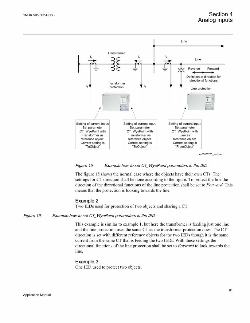
Transformer protection
Transformer
Line
Line
Setting of current input:Set parameter
CT_WyePoint with Transformer as
reference object.Correct setting is
"ToObject"
ForwardReverse
Definition of direction for directional functions
Line protection
Setting of current input:Set parameter
CT_WyePoint with Transformer as
reference object.Correct setting is
"ToObject"
Setting of current input:Set parameter
CT_WyePoint withLine as
reference object.Correct setting is
"FromObject"
en05000753_ansi.vsd
IsIs
Ip Ip Ip
ANSI05000753 V1 EN
Figure 15: Example how to set CT_WyePoint parameters in the IED
The figure 15 shows the normal case where the objects have their own CTs. Thesettings for CT direction shall be done according to the figure. To protect the line thedirection of the directional functions of the line protection shall be set to Forward. Thismeans that the protection is looking towards the line.
Example 2Two IEDs used for protection of two objects and sharing a CT.
Figure 16: Example how to set CT_WyePoint parameters in the IED
This example is similar to example 1, but here the transformer is feeding just one lineand the line protection uses the same CT as the transformer protection does. The CTdirection is set with different reference objects for the two IEDs though it is the samecurrent from the same CT that is feeding the two IEDs. With these settings thedirectional functions of the line protection shall be set to Forward to look towards theline.
Example 3One IED used to protect two objects.
1MRK 505 302-UUS - Section 4Analog inputs
61Application Manual

Transformer and Line protection
Transformer
Line
Setting of current input:Set parameter
CT_WyePoint with Transformer as
reference object.Correct setting is
"ToObject"
ReverseForward
Definition of direction for directional
line functions
Setting of current input:Set parameter
CT_WyePoint with Transformer as
reference object.Correct setting is
"ToObject"
en05000461_ansi.vsd
ANSI05000461 V1 EN
Figure 17: Example how to set CT_WyePoint parameters in the IED
In this example one IED includes both transformer and line protection and the lineprotection uses the same CT as the transformer protection does. For both current inputchannels the CT direction is set with the transformer as reference object. This meansthat the direction Forward for the line protection is towards the transformer. To looktowards the line the direction of the directional functions of the line protection must beset to Reverse. The direction Forward/Reverse is related to the reference object that isthe transformer in this case.
When a function is set to Reverse and shall protect an object in reverse direction it shallbe noted that some directional functions are not symmetrical regarding the reach inforward and reverse direction. It is in first hand the reach of the directional criteria thatcan differ. Normally it is not any limitation but it is advisable to have it in mind andcheck if it is acceptable for the application in question.
If the IED has a sufficient number of analog current inputs an alternative solution isshown in figure 18. The same currents are fed to two separate groups of inputs and the
Section 4 1MRK 505 302-UUS -Analog inputs
62Application Manual

line and transformer protection functions are configured to the different inputs. The CTdirection for the current channels to the line protection is set with the line as referenceobject and the directional functions of the line protection shall be set to Forward toprotect the line.
Transformer and Line protection
Transformer
Line
Setting of current inputfor transformer functions:
Set parameter CT_WyePoint with
Transformer as reference object.Correct setting is
"ToObject"
ForwardReverse
Definition of direction for directional
line functions
Setting of current inputfor transformer functions:
Set parameter CT_WyePoint with
Transformer as reference object.Correct setting is
"ToObject"
Setting of current inputfor line functions:
Set parameter CT_WyePoint with
Line as reference object.Correct setting is
"FromObject"
en05000462_ansi.vsd
ANSI05000462 V1 EN
Figure 18: Example how to set CT_WyePoint parameters in the IED
1MRK 505 302-UUS - Section 4Analog inputs
63Application Manual
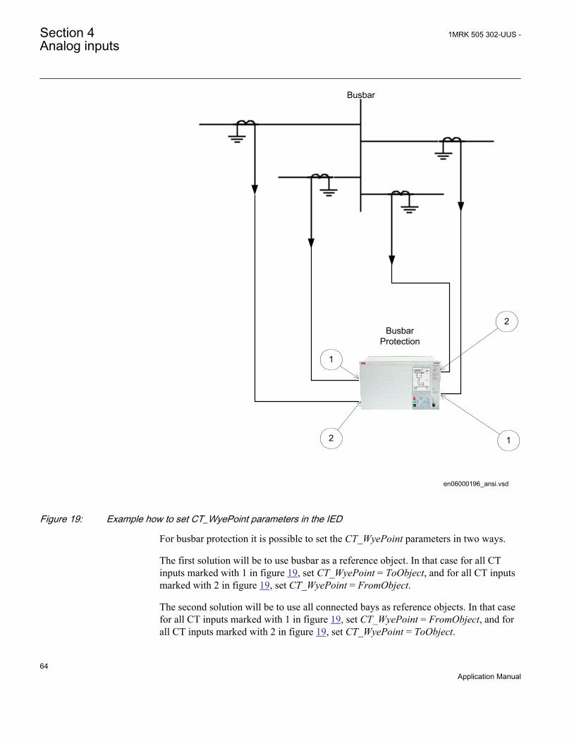
BusbarProtection
Busbar
1
2
2
1
en06000196_ansi.vsd
ANSI06000196 V1 EN
Figure 19: Example how to set CT_WyePoint parameters in the IED
For busbar protection it is possible to set the CT_WyePoint parameters in two ways.
The first solution will be to use busbar as a reference object. In that case for all CTinputs marked with 1 in figure 19, set CT_WyePoint = ToObject, and for all CT inputsmarked with 2 in figure 19, set CT_WyePoint = FromObject.
The second solution will be to use all connected bays as reference objects. In that casefor all CT inputs marked with 1 in figure 19, set CT_WyePoint = FromObject, and forall CT inputs marked with 2 in figure 19, set CT_WyePoint = ToObject.
Section 4 1MRK 505 302-UUS -Analog inputs
64Application Manual
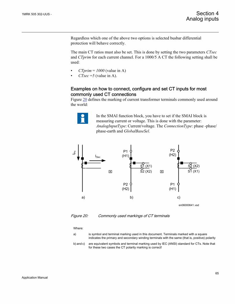
Regardless which one of the above two options is selected busbar differentialprotection will behave correctly.
The main CT ratios must also be set. This is done by setting the two parameters CTsecand CTprim for each current channel. For a 1000/5 A CT the following setting shall beused:
• CTprim = 1000 (value in A)• CTsec =5 (value in A).
Examples on how to connect, configure and set CT inputs for mostcommonly used CT connectionsFigure 20 defines the marking of current transformer terminals commonly used aroundthe world:
In the SMAI function block, you have to set if the SMAI block ismeasuring current or voltage. This is done with the parameter:AnalogInputType: Current/voltage. The ConnectionType: phase -phase/phase-earth and GlobalBaseSel.
ISec
I Pri
S1 (X1)
P1(H1)
P2(H2)
S2 (X2)
P2(H2)
P1(H1)
x x
a) b) c)
en06000641.vsd
S2 (X2) S1 (X1)
IEC06000641 V1 EN
Figure 20: Commonly used markings of CT terminals
Where:
a) is symbol and terminal marking used in this document. Terminals marked with a squareindicates the primary and secondary winding terminals with the same (that is, positive) polarity
b) and c) are equivalent symbols and terminal marking used by IEC (ANSI) standard for CTs. Note thatfor these two cases the CT polarity marking is correct!
1MRK 505 302-UUS - Section 4Analog inputs
65Application Manual

It shall be noted that depending on national standard and utility practices, the ratedsecondary current of a CT has typically one of the following values:
• 1A• 5A
However in some cases the following rated secondary currents are used as well:
• 2A• 10A
The IED fully supports all of these rated secondary values.
It is recommended to:
• use 1A rated CT input into the IED in order to connect CTs with1A and 2A secondary rating
• use 5A rated CT input into the IED in order to connect CTs with5A and 10A secondary rating
Example on how to connect a wye connected three-phase CT set to theIEDFigure 21 gives an example about the wiring of a wye connected three-phase CT set tothe IED. It gives also an overview of the actions which are needed to make thismeasurement available to the built-in protection and control functions within the IEDas well.
For correct terminal designations, see the connection diagrams valid forthe delivered IED.
Section 4 1MRK 505 302-UUS -Analog inputs
66Application Manual

Protected Object
CT 600/5Star Connected
IED
ANSI3000002-2-en.vsd
1 2
3
4
SMAI_20
AI_
A
I_B
I_C
B C
I_A
I_B
I_C
ANSI13000002 V2 EN
Figure 21: Wye connected three-phase CT set with wye point towards the protected object
Where:
1) The drawing shows how to connect three individual phase currents from a wye connected three-phase CT set to the three CT inputs of the IED.
2) The current inputs are located in the TRM. It shall be noted that for all these current inputs thefollowing setting values shall be entered for the example shown in Figure21.'
• CTprim=600A• CTsec=5A• CTStarPoint=ToObject
Inside the IED only the ratio of the first two parameters is used. The third parameter(CTStarPoint=ToObject) as set in this example causes no change on the measured currents. Inother words, currents are already measured towards the protected object.
Table continues on next page
1MRK 505 302-UUS - Section 4Analog inputs
67Application Manual
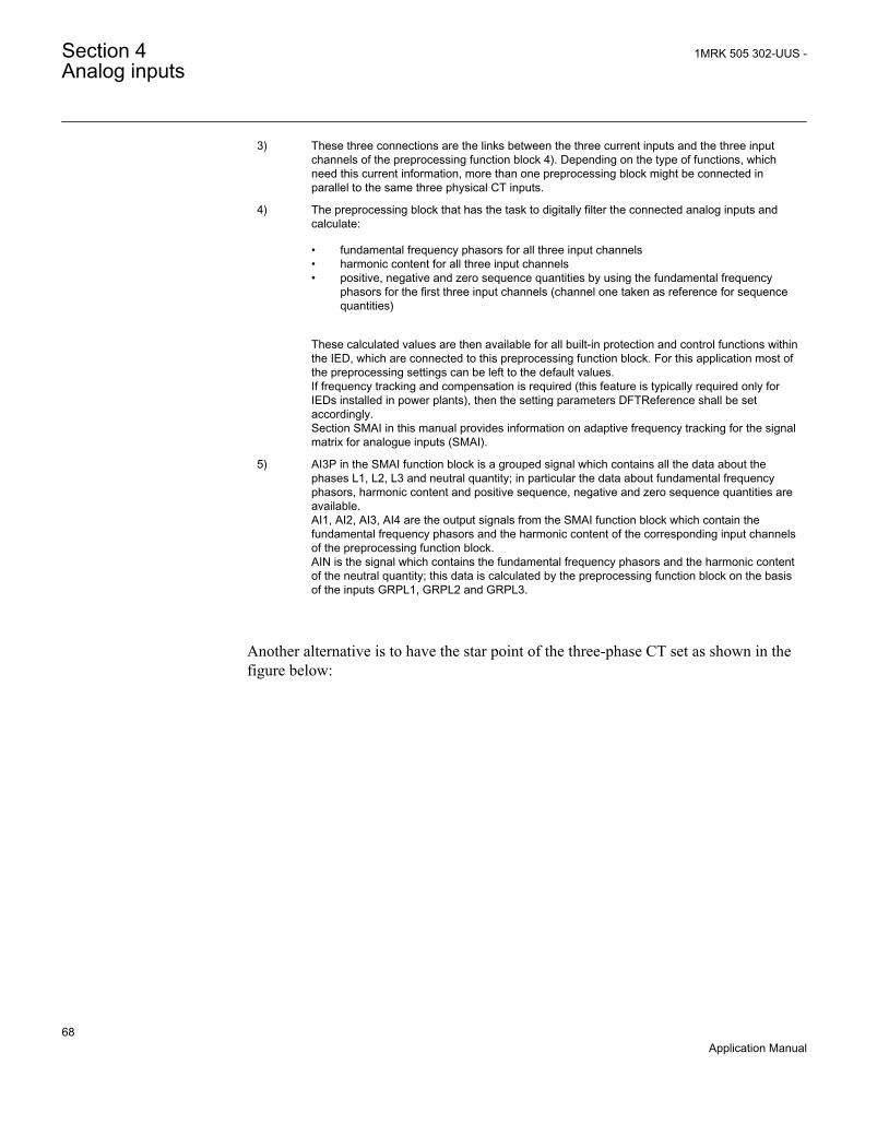
3) These three connections are the links between the three current inputs and the three inputchannels of the preprocessing function block 4). Depending on the type of functions, whichneed this current information, more than one preprocessing block might be connected inparallel to the same three physical CT inputs.
4) The preprocessing block that has the task to digitally filter the connected analog inputs andcalculate:
• fundamental frequency phasors for all three input channels• harmonic content for all three input channels• positive, negative and zero sequence quantities by using the fundamental frequency
phasors for the first three input channels (channel one taken as reference for sequencequantities)
These calculated values are then available for all built-in protection and control functions withinthe IED, which are connected to this preprocessing function block. For this application most ofthe preprocessing settings can be left to the default values.If frequency tracking and compensation is required (this feature is typically required only forIEDs installed in power plants), then the setting parameters DFTReference shall be setaccordingly.Section SMAI in this manual provides information on adaptive frequency tracking for the signalmatrix for analogue inputs (SMAI).
5) AI3P in the SMAI function block is a grouped signal which contains all the data about thephases L1, L2, L3 and neutral quantity; in particular the data about fundamental frequencyphasors, harmonic content and positive sequence, negative and zero sequence quantities areavailable.AI1, AI2, AI3, AI4 are the output signals from the SMAI function block which contain thefundamental frequency phasors and the harmonic content of the corresponding input channelsof the preprocessing function block.AIN is the signal which contains the fundamental frequency phasors and the harmonic contentof the neutral quantity; this data is calculated by the preprocessing function block on the basisof the inputs GRPL1, GRPL2 and GRPL3.
Another alternative is to have the star point of the three-phase CT set as shown in thefigure below:
Section 4 1MRK 505 302-UUS -Analog inputs
68Application Manual
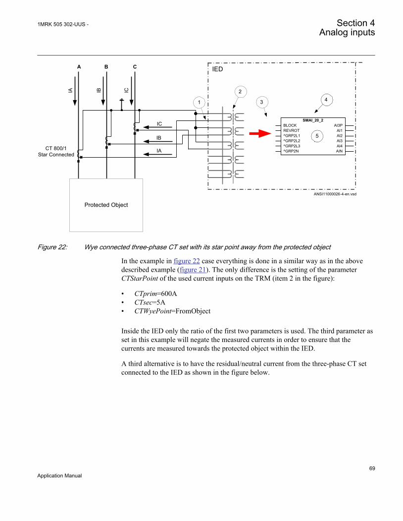
Protected Object
CT 800/1Star Connected
IED
ANSI11000026-4-en.vsd
4 1
2
3
AIA IB IC
B C
IA
IB
ICSMAI_20_2
BLOCKREVROT^GRP2L1^GRP2L2^GRP2L3^GRP2N
AI3PAI1AI2AI3AI4AIN
5
ANSI11000026 V4 EN
Figure 22: Wye connected three-phase CT set with its star point away from the protected object
In the example in figure 22 case everything is done in a similar way as in the abovedescribed example (figure 21). The only difference is the setting of the parameterCTStarPoint of the used current inputs on the TRM (item 2 in the figure):
• CTprim=600A• CTsec=5A• CTWyePoint=FromObject
Inside the IED only the ratio of the first two parameters is used. The third parameter asset in this example will negate the measured currents in order to ensure that thecurrents are measured towards the protected object within the IED.
A third alternative is to have the residual/neutral current from the three-phase CT setconnected to the IED as shown in the figure below.
1MRK 505 302-UUS - Section 4Analog inputs
69Application Manual

789101112
123456
A
IA IB IC
B C
Protected Object
CT 800/1Wye Connected IA
IB
ICAI 01 (I)
AI 02 (I)
AI 03 (I)
AI 04 (I)
AI 05 (I)
AI 06 (I)
IN
IED
1
3
4
2
5
ANSI06000644-2-en.vsd
6
SMAI2BLOCK AI3P
AI1AI2AI3AI4AIN
^GRP2_B^GRP2_A
^GRP2_C^GRP2NTYPE
ANSI06000644 V2 EN
Figure 23: Wye connected three-phase CT set with its star point away from the protected object and the residual/neutral current connected to the IED
Where:
1) The drawing shows how to connect three individual phase currents from a wye connected three-phase CT set to the three CT inputs of the IED.
2) shows how to connect residual/neutral current from the three-phase CT set to the fourth inputsin the IED. It shall be noted that if this connection is not made, the IED will still calculate thiscurrent internally by vectorial summation of the three individual phase currents.
3) is the TRM where these current inputs are located. It shall be noted that for all these currentinputs the following setting values shall be entered.
• CTprim=800A• CTsec=1A• CTStarPoint=FromObject• ConnectionType=Ph-N
Inside the IED only the ratio of the first two parameters is used. The third parameter as set inthis example will have no influence on the measured currents (that is, currents are alreadymeasured towards the protected object).
4) are three connections made in the Signal Matrix tool (SMT), Application configuration tool(ACT), which connects these three current inputs to the first three input channels on thepreprocessing function block 6). Depending on the type of functions, which need this currentinformation, more than one preprocessing block might be connected in parallel to these threeCT inputs.
Table continues on next page
Section 4 1MRK 505 302-UUS -Analog inputs
70Application Manual

5) is a connection made in the Signal Matrix tool (SMT), Application configuration tool (ACT),which connects the residual/neutral current input to the fourth input channel of thepreprocessing function block 6). Note that this connection in SMT shall not be done if the residual/neutral current is not connected to the IED. In that case the pre-processing block will calculate itby vectorial summation of the three individual phase currents.
6) is a Preprocessing block that has the task to digitally filter the connected analog inputs andcalculate:
• fundamental frequency phasors for all four input channels• harmonic content for all four input channels• positive, negative and zero sequence quantities by using the fundamental frequency
phasors for the first three input channels (channel one taken as reference for sequencequantities)
These calculated values are then available for all built-in protection and control functions withinthe IED, which are connected to this preprocessing function block in the configuration tool. Forthis application most of the preprocessing settings can be left to the default values.If frequency tracking and compensation is required (this feature is typically required only forIEDs installed in the generating stations), then the setting parameters DFTReference shall beset accordingly.
Example how to connect delta connected three-phase CT set to the IEDFigure 24 gives an example how to connect a delta connected three-phase CT set to theIED. It gives an overview of the required actions by the user in order to make thismeasurement available to the built-in protection and control functions in the IED as well.
For correct terminal designations, see the connection diagrams valid forthe delivered IED.
1MRK 505 302-UUS - Section 4Analog inputs
71Application Manual
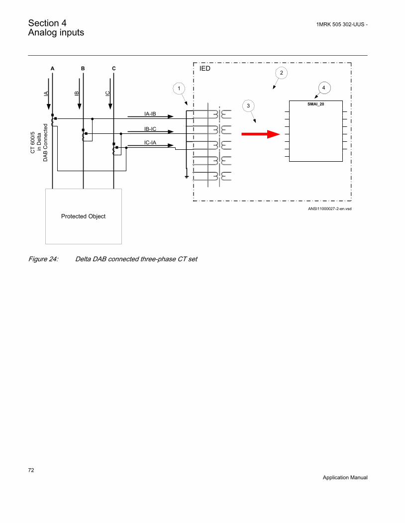
A
IA IB IC
B C
Protected Object
IED
CT
600/
5 in
Del
taD
AB
Con
nect
ed
IA-IB
IB-IC
IC-IA
1
2
3
4
ANSI11000027-2-en.vsd
SMAI_20
ANSI11000027 V2 EN
Figure 24: Delta DAB connected three-phase CT set
Section 4 1MRK 505 302-UUS -Analog inputs
72Application Manual

Where:
1) shows how to connect three individual phase currents from a delta connected three-phase CTset to three CT inputs of the IED.
2) is the TRM where these current inputs are located. It shall be noted that for all these currentinputs the following setting values shall be entered.CTprim=600ACTsec=5A
• CTWyePoint=ToObject• ConnectionType=Ph-Ph
3) are three connections made in Signal Matrix Tool (SMT), Application configuration tool (ACT),which connect these three current inputs to first three input channels of the preprocessingfunction block 4). Depending on the type of functions which need this current information, morethen one preprocessing block might be connected in parallel to these three CT inputs.
4) is a Preprocessing block that has the task to digitally filter the connected analog inputs andcalculate:
• fundamental frequency phasors for all three input channels• harmonic content for all three input channels• positive, negative and zero sequence quantities by using the fundamental frequency
phasors for the first three input channels (channel one taken as reference for sequencequantities)
These calculated values are then available for all built-in protection and control functions withinthe IED, which are connected to this preprocessing function block. For this application most ofthe preprocessing settings can be left to the default values.If frequency tracking and compensation is required (this feature is typically required only forIEDs installed in the generating stations) then the setting parameters DFTReference shall beset accordingly.
Another alternative is to have the delta connected CT set as shown in figure 25:
1MRK 505 302-UUS - Section 4Analog inputs
73Application Manual

A
IA IB IC
B C
Protected Object
IED
CT
800/
1 in
Del
taD
CA
Con
nect
ed
IC-IB
IB-IA
IA-IC
2
3
4
ANSI11000028-2-en.vsd
SMAI_20
ANSI11000028 V2 EN
Figure 25: Delta DAC connected three-phase CT set
In this case, everything is done in a similar way as in the above described example,except that for all used current inputs on the TRM the following setting parametersshall be entered:
CTprim=800A
CTsec=1A
• CTWyePoint=ToObject• ConnectionType=Ph-Ph
It is important to notice the references in SMAI. As inputs at Ph-Ph are expected to beA-B, B-Crespectively C-A we need to tilt 180º by setting ToObject.
Example how to connect single-phase CT to the IEDFigure 26 gives an example how to connect the single-phase CT to the IED. It gives anoverview of the required actions by the user in order to make this measurementavailable to the built-in protection and control functions within the IED as well.
Section 4 1MRK 505 302-UUS -Analog inputs
74Application Manual

For correct terminal designations, see the connection diagrams valid forthe delivered IED.
Protected Object
A B C
IED
INP
2
4
ANSI11000029-3-en.vsd
3
CT
1000
/1
a)
b)INS
INS(+)
(+)
(-)
(-)(+)
(-)
1 SMAI_20_2BLOCKREVROT^GRP2_A^GRP2_B^GRP2_C^GRP2_N
AI3PAI1AI2AI3AI4AIN
ANSI11000029 V3 EN
Figure 26: Connections for single-phase CT input
1MRK 505 302-UUS - Section 4Analog inputs
75Application Manual

Where:
1) shows how to connect single-phase CT input in the IED.
2) is TRM where these current inputs are located. It shall be noted that for all these currentinputs the following setting values shall be entered.For connection (a) shown in figure 26:CTprim = 1000 ACTsec = 1ACTWyePoint=ToObject For connection (b) shown in figure 26:CTprim = 1000 ACTsec = 1ACTWyePoint=FromObject
3) shows the connection made in SMT tool, which connect this CT input to the fourth inputchannel of the preprocessing function block 4).
4) is a Preprocessing block that has the task to digitally filter the connected analog inputs andcalculate values. The calculated values are then available for all built-in protection andcontrol functions within the IED, which are connected to this preprocessing function block.If frequency tracking and compensation is required (this feature is typically required only forIEDs installed in the power plants) then the setting parameters DFTReference shall be setaccordingly.
Setting of voltage channelsAs the IED uses primary system quantities the main VT ratios must be known to theIED. This is done by setting the two parameters VTsec and VTprim for each voltagechannel. The phase-to-phase value can be used even if each channel is connected to aphase-to-ground voltage from the VT.
ExampleConsider a VT with the following data:
132kV 120V3 3
EQUATION1937 V1 EN (Equation 1)
The following setting should be used: VTprim=132 (value in kV) VTsec=120 (value inV)
Examples how to connect, configure and set VT inputs for mostcommonly used VT connectionsFigure 27 defines the marking of voltage transformer terminals commonly used aroundthe world.
Section 4 1MRK 505 302-UUS -Analog inputs
76Application Manual

A(H1)
B(H2)
b(X2)
a(X1)
A(H1)
N(H2)
n(X2)
a(X1)
b) c)
A(H1)
N(H2)
dn(X2)
da(X1)
d)
VPri
+ +VSec
a)
ANSI11000175_1_en.vsdANSI11000175 V1 EN
Figure 27: Commonly used markings of VT terminals
Where:
a) is the symbol and terminal marking used in this document. Terminals marked with a squareindicate the primary and secondary winding terminals with the same (positive) polarity
b) is the equivalent symbol and terminal marking used by IEC (ANSI) standard for phase-to-ground connected VTs
c) is the equivalent symbol and terminal marking used by IEC (ANSI) standard for open deltaconnected VTs
d) is the equivalent symbol and terminal marking used by IEC (ANSI) standard for phase-to-phaseconnected VTs
It shall be noted that depending on national standard and utility practices the ratedsecondary voltage of a VT has typically one of the following values:
• 100 V• 110 V• 115 V• 120 V• 230 V
The IED fully supports all of these values and most of them will be shown in thefollowing examples.
Examples on how to connect a three phase-to-ground connected VT tothe IEDFigure 28 gives an example on how to connect the three phase-to-ground connectedVT to the IED. It as well gives overview of required actions by the user in order tomake this measurement available to the built-in protection and control functions withinthe IED.
For correct terminal designations, see the connection diagrams valid forthe delivered IED.
1MRK 505 302-UUS - Section 4Analog inputs
77Application Manual
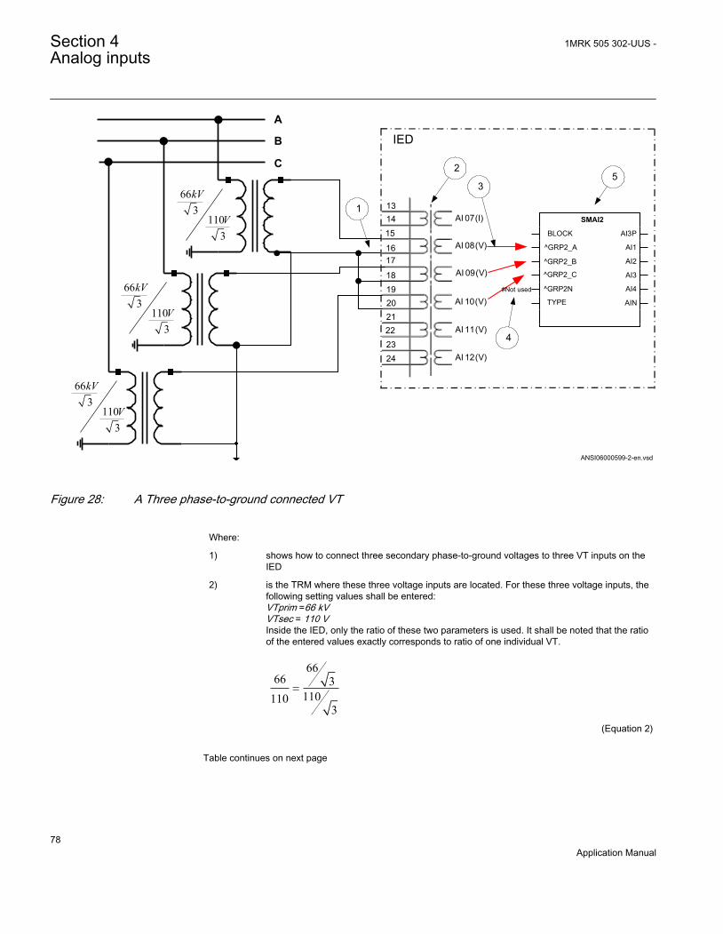
192021222324
131415
1617
18
A
AI 07 (I)
AI 08 (V)
AI 09 (V)
AI 10 (V)
AI 11 (V)
AI 12 (V)
IED B
C
663
1103
kV
V
1
3
2
663
1103
kV
V
663
1103
kV
V
#Not used
5
ANSI06000599-2-en.vsd
SMAI2
BLOCK
^GRP2_A
TYPE
AI3P
AI1
AI2
AI3
AI4
AIN
^GRP2_B
^GRP2_C
^GRP2N
4
ANSI06000599 V2 EN
Figure 28: A Three phase-to-ground connected VT
Where:
1) shows how to connect three secondary phase-to-ground voltages to three VT inputs on theIED
2) is the TRM where these three voltage inputs are located. For these three voltage inputs, thefollowing setting values shall be entered:VTprim =66 kVVTsec = 110 VInside the IED, only the ratio of these two parameters is used. It shall be noted that the ratioof the entered values exactly corresponds to ratio of one individual VT.
6666 3
1101103
=
EQUATION1903 V1 EN (Equation 2)
Table continues on next page
Section 4 1MRK 505 302-UUS -Analog inputs
78Application Manual

3) are three connections made in Signal Matrix Tool (SMT), which connect these three voltageinputs to first three input channels of the preprocessing function block 5). Depending on thetype of functions which need this voltage information, more then one preprocessing blockmight be connected in parallel to these three VT inputs.
4) shows that in this example the fourth (that is, residual) input channel of the preprocessingblock is not connected in SMT tool. Thus the preprocessing block will automatically calculate3Vo inside by vectorial sum from the three phase to ground voltages connected to the firstthree input channels of the same preprocessing block. Alternatively, the fourth input channelcan be connected to open delta VT input, as shown in figure 30.
5) is a Preprocessing block that has the task to digitally filter the connected analog inputs andcalculate:
• fundamental frequency phasors for all four input channels• harmonic content for all four input channels• positive, negative and zero sequence quantities by using the fundamental frequency
phasors for the first three input channels (channel one taken as reference forsequence quantities)
These calculated values are then available for all built-in protection and control functionswithin the IED, which are connected to this preprocessing function block in the configurationtool. For this application most of the preprocessing settings can be left to the default values.However the following settings shall be set as shown here:VBase=66 kV (that is, rated Ph-Ph voltage)If frequency tracking and compensation is required (this feature is typically required only forIEDs installed in the generating stations) then the setting parameters DFTReference shall beset accordingly.
Example on how to connect a phase-to-phase connected VT to the IEDFigure 29 gives an example how to connect a phase-to-phase connected VT to the IED.It gives an overview of the required actions by the user in order to make thismeasurement available to the built-in protection and control functions within the IEDas well. It shall be noted that this VT connection is only used on lower voltage levels(that is, rated primary voltage below 40 kV).
1MRK 505 302-UUS - Section 4Analog inputs
79Application Manual
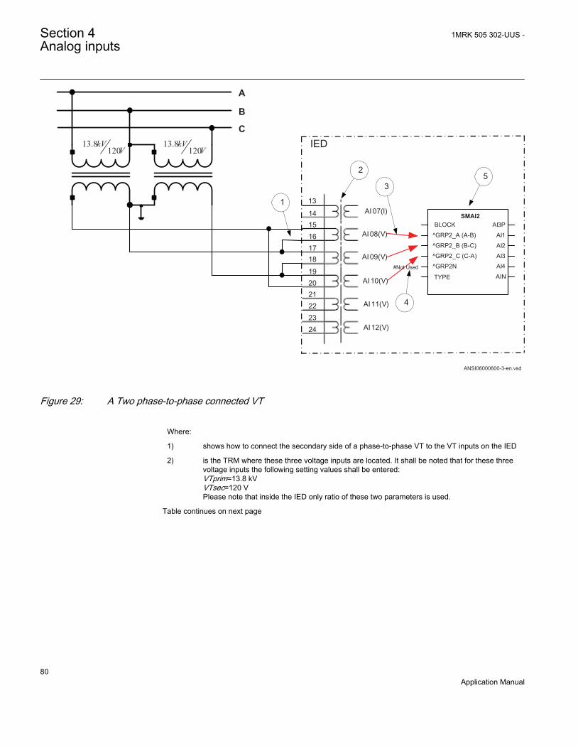
192021222324
13
1415161718
A
AI 07(I)
AI08 (V)
AI09 (V)
AI10(V)
AI11(V)
AI12(V)
IED
B
C13.8
120kV
V
1
2
3
#Not Used
13.8120
kVV
5
ANSI06000600-3-en.vsd
SMAI2BLOCK
^GRP2_A (A-B)
^GRP2_B (B-C)
^GRP2_C (C-A)
^GRP2N
TYPE
AI3P
AI1
AI2
AI3
AI4
AIN
4
ANSI06000600 V3 EN
Figure 29: A Two phase-to-phase connected VT
Where:
1) shows how to connect the secondary side of a phase-to-phase VT to the VT inputs on the IED
2) is the TRM where these three voltage inputs are located. It shall be noted that for these threevoltage inputs the following setting values shall be entered:VTprim=13.8 kVVTsec=120 VPlease note that inside the IED only ratio of these two parameters is used.
Table continues on next page
Section 4 1MRK 505 302-UUS -Analog inputs
80Application Manual
3) are three connections made in the Signal Matrix tool (SMT), Application configuration tool(ACT), which connects these three voltage inputs to first three input channels of thepreprocessing function block 5). Depending on the type of functions, which need this voltageinformation, more than one preprocessing block might be connected in parallel to these threeVT inputs
4) shows that in this example the fourth (that is, residual) input channel of the preprocessing blockis not connected in SMT. Note. If the paameters VA, VB, VC, VN should be used the open deltamust be connected here.
5) Preprocessing block has a task to digitally filter the connected analog inputs and calculate:
• fundamental frequency phasors for all four input channels• harmonic content for all four input channels• positive, negative and zero sequence quantities by using the fundamental frequency
phasors for the first three input channels (channel one taken as reference for sequencequantities)
These calculated values are then available for all built-in protection and control functions withinthe IED, which are connected to this preprocessing function block in the configuration tool. Forthis application most of the preprocessing settings can be left to the default values. Howeverthe following settings shall be set as shown here:ConnectionType=Ph-PhVBase=13.8 kVIf frequency tracking and compensation is required (this feature is typically required only forIEDs installed in the generating stations) then the setting parameters DFTReference shall beset accordingly.
Example on how to connect an open delta VT to the IED for highimpedance grounded or ungrounded netwoeksFigure 30 gives an example about the wiring of an open delta VT to the IED for highimpedance grounded or ungrounded power systems. It shall be noted that this type ofVT connection presents a secondary voltage proportional to 3V0 to the IED.
In case of a solid ground fault close to the VT location the primary value of 3Vo willbe equal to:
3 3 3Ph Ph Ph GndVo V V- -= × = ×
EQUATION1922-ANSI V1 EN (Equation 3)
The primary rated voltage of an open Delta VT is always equal to VPh-Gnd. Three seriesconnected VT secondary windings gives a secondary voltage equal to three times theindividual VT secondary winding rating. Thus the secondary windings of open deltaVTs quite often have a secondary rated voltage equal to one third of the rated phase-to-phase VT secondary voltage (110/3V in this particular example).
Figure 30 gives overview of required actions by the user in order to make thismeasurement available to the built-in protection and control functions within the IEDas well.
1MRK 505 302-UUS - Section 4Analog inputs
81Application Manual

192021222324
13141516
1718
A
AI 07 (I)
AI 08 (V)
AI 09 (V)
AI 10 (V)
AI 11 (V)
AI 12 (V)
IED B
C
6.63
1103
kV
V
+3Vo
6.63
1103
kV
V
6.63
1103
kV
V
1
2
4
3
# Not Used
5
ANSI06000601-2-en.vsd
# Not Used
# Not Used
SMAI2
BLOCK
^GRP2_A
^GRP2_B
^GRP2_C
^GRP2N
TYPE
AI3P
AI1
AI2
AI3
AI4
AIN
ANSI06000601 V2 EN
Figure 30: Open delta connected VT in high impedance grounded power system
Section 4 1MRK 505 302-UUS -Analog inputs
82Application Manual

Where:
1) shows how to connect the secondary side of the open delta VT to one VT input on the IED.
+3Vo shall be connected to the IED
2) is the TRM where this voltage input is located. It shall be noted that for this voltage input thefollowing setting values shall be entered:
3 6.6 11.43VTprim kV= × =
EQUATION1923 V1 EN (Equation 4)
110sec 3 110
3VT V= × =
EQUATION1924 V1 EN (Equation 5)
Inside the IED, only the ratio of these two parameters is used. It shall be noted that the ratioof the entered values exactly corresponds to ratio of one individual open delta VT.
6.63 6.6 3
1101103
×=
EQUATION1925 V1 EN (Equation 6)
3) shows that in this example the first three input channel of the preprocessing block is notconnected in SMT tool or ACT tool.
4) shows the connection made in Signal Matrix Tool (SMT), Application configuration tool(ACT), which connect this voltage input to the fourth input channel of the preprocessingfunction block 5).
5) is a Preprocessing block that has the task to digitally filter the connected analog input andcalculate:
• fundamental frequency phasors for all four input channels• harmonic content for all four input channels• positive, negative and zero sequence quantities by using the fundamental frequency
phasors for the first three input channels (channel one taken as reference for sequencequantities)
These calculated values are then available for all built-in protection and control functionswithin the IED, which are connected to this preprocessing function block in the configurationtool. For this application most of the preprocessing settings can be left to the default values.If frequency tracking and compensation is required (this feature is typically required only forIEDs installed in the generating stations ) then the setting parameters DFTReference shallbe set accordingly.
1MRK 505 302-UUS - Section 4Analog inputs
83Application Manual

Example how to connect the open delta VT to the IED for lowimpedance grounded or solidly grounded power systemsFigure 31 gives an example about the connection of an open delta VT to the IED forlow impedance grounded or solidly grounded power systems. It shall be noted that thistype of VT connection presents secondary voltage proportional to 3V0 to the IED.
In case of a solid ground fault close to the VT location the primary value of 3Vo willbe equal to:
33
Ph PhPh Gnd
VVo V-
-= =
EQUATION1927-ANSI V1 EN (Equation 7)
The primary rated voltage of such VT is always equal to VPh-Gnd. Therefore, threeseries connected VT secondary windings will give the secondary voltage equal only toone individual VT secondary winding rating. Thus the secondary windings of suchopen delta VTs quite often has a secondary rated voltage close to rated phase-to-phaseVT secondary voltage, that is, 115V or 115/√3V as in this particular example. Figure31 gives an overview of the actions which are needed to make this measurementavailable to the built-in protection and control functions within the IED.
Section 4 1MRK 505 302-UUS -Analog inputs
84Application Manual

192021222324
131415161718
A
AI07 (I)
AI08 (V)
AI09 (V)
AI10 (V)
AI11 (V)
AI12 (V)
IED B
C
1383
1153
kV
V
+3Vo
1383
1153
kV
V
1383
1153
kV
V
1
2
4
3
ANSI06000602-2-en.vsd
5
# Not Used
# Not Used
# Not Used
SMAI2
BLOCK
^GRP2_A
^GRP2_B
^GRP2_C
^GRP2N
TYPE
AI3P
AI1
AI2
AI3
AI4
AIN
ANSI06000602 V2 EN
Figure 31: Open delta connected VT in low impedance or solidly grounded power system
1MRK 505 302-UUS - Section 4Analog inputs
85Application Manual

Where:
1) shows how to connect the secondary side of open delta VT to one VT input in the IED.
+3Vo shall be connected to the IED.
2) is TRM where this voltage input is located. It shall be noted that for this voltage inputthe following setting values shall be entered:
1383 138
3VTprim kV= × =
EQUATION1928 V1 EN (Equation 8)
115sec 3 115
3VT V= × =
EQUATION1929 V1 EN (Equation 9)
Inside the IED, only the ratio of these two parameters is used. It shall be noted thatthe ratio of the entered values exactly corresponds to ratio of one individual opendelta VT.
138138 3
1151153
=
EQUATION1930 V1 EN (Equation 10)
3) shows that in this example the first three input channel of the preprocessing block isnot connected in SMT tool.
4) shows the connection made in Signal Matrix Tool (SMT), which connect this voltageinput to the fourth input channel of the preprocessing function block 4).
5) preprocessing block has a task to digitally filter the connected analog inputs andcalculate:
• fundamental frequency phasors for all four input channels• harmonic content for all four input channels• positive, negative and zero sequence quantities by using the fundamental
frequency phasors for the first three input channels (channel one taken asreference for sequence quantities)
These calculated values are then available for all built-in protection and controlfunctions within the IED, which are connected to this preprocessing function block inthe configuration tool. For this application most of the preprocessing settings can beleft to the default values.If frequency tracking and compensation is required (this feature is typically requiredonly for IEDs installed in the generating stations) then the setting parametersDFTReference shall be set accordingly.
Section 4 1MRK 505 302-UUS -Analog inputs
86Application Manual

Example on how to connect a neutral point VT to the IEDFigure 32 gives an example on how to connect a neutral point VT to the IED. This typeof VT connection presents secondary voltage proportional to V0 to the IED.
In case of a solid ground fault in high impedance grounded or ungrounded systems theprimary value of V0 voltage will be equal to:
03
ph phph Gnd
VV V--= =
EQUATION1932 V2 EN (Equation 11)
Figure 32 gives an overview of required actions by the user in order to make thismeasurement available to the built-in protection and control functions within the IEDas well.
Protected Object
19
20
21
22
23
24
13
14
15
16
17
18
A B CAI07 (I)
AI08 (I)
AI09 (I)
AI10 (V)
AI11 (V)
AI12 (V)
IED
6.63
100
kV
V
RVo
1
2
3
4
ANSI06000603-2-en.vsd
5
SMAI2
BLOCK
^GRP2_A
^GRP2_B
^GRP2_C
^GRP2N
TYPE
AI3P
AI1
AI2
AI3
AI4
AIN
# Not Used
# Not Used
# Not Used
ANSI06000603 V2 EN
Figure 32: Neutral point connected VT
1MRK 505 302-UUS - Section 4Analog inputs
87Application Manual
Where:
1) shows how to connect the secondary side of neutral point VT to one VT input in the IED.
V0 shall be connected to the IED.
2) is the TRM or AIM where this voltage input is located. For this voltage input the followingsetting values shall be entered:
6.63.81
3VTprim kV= =
EQUATION1933 V1 EN (Equation 12)
sec 100VT V=
EQUATION1934 V1 EN (Equation 13)
Inside the IED, only the ratio of these two parameters is used. It shall be noted that the ratio ofthe entered values exactly corresponds to ratio of the neutral point VT.
3) shows that in this example the first three input channel of the preprocessing block is notconnected in SMT tool or ACT tool.
4) shows the connection made in Signal Matrix Tool (SMT), Application configuration tool (ACT),which connects this voltage input to the fourth input channel of the preprocessing function block5).
5) is a preprocessing block that has the task to digitally filter the connected analog inputs andcalculate:
• fundamental frequency phasors for all four input channels• harmonic content for all four input channels• positive, negative and zero sequence quantities by using the fundamental frequency
phasors for the first three input channels (channel one taken as reference for sequencequantities)
These calculated values are then available for all built-in protection and control functions withinthe IED, which are connected to this preprocessing function block in the configuration tool. Forthis application most of the preprocessing settings can be left to the default values.If frequency tracking and compensation is required (this feature is typically required only forIEDs installed in the generating stations) then the setting parameters DFTReference shall beset accordingly.
Section 4 1MRK 505 302-UUS -Analog inputs
88Application Manual
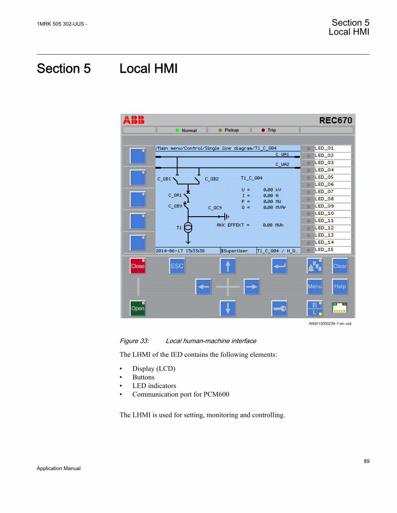
Section 5 Local HMI
ANSI13000239-1-en.vsdANSI13000239 V1 EN
Figure 33: Local human-machine interface
The LHMI of the IED contains the following elements:
• Display (LCD)• Buttons• LED indicators• Communication port for PCM600
The LHMI is used for setting, monitoring and controlling.
1MRK 505 302-UUS - Section 5Local HMI
89Application Manual

5.1 Display
The LHMI includes a graphical monochrome display with a resolution of 320 x 240pixels. The character size can vary.
The display view is divided into four basic areas.
IEC13000063-2-en.vsd
1
3 4
2
IEC13000063 V2 EN
Figure 34: Display layout
1 Path
2 Content
3 Status
4 Scroll bar (appears when needed)
The function button panel shows on request what actions are possible with the functionbuttons. Each function button has a LED indication that can be used as a feedbacksignal for the function button control action. The LED is connected to the requiredsignal with PCM600.
Section 5 1MRK 505 302-UUS -Local HMI
90Application Manual

IEC13000281-1-en.vsdGUID-C98D972D-D1D8-4734-B419-161DBC0DC97B V1 EN
Figure 35: Function button panel
The alarm LED panel shows on request the alarm text labels for the alarm LEDs. Threealarm LED pages are available.
IEC13000240-1-en.vsdGUID-5157100F-E8C0-4FAB-B979-FD4A971475E3 V1 EN
Figure 36: Alarm LED panel
The function button and alarm LED panels are not visible at the same time. Each panelis shown by pressing one of the function buttons or the Multipage button. Pressing theESC button clears the panel from the display. Both the panels have dynamic width thatdepends on the label string length that the panel contains.
1MRK 505 302-UUS - Section 5Local HMI
91Application Manual
5.2 LEDs
The LHMI includes three protection status LEDs above the display: Normal, Pickupand Trip.
There are 15 programmable alarm LEDs on the front of the LHMI. Each LED canindicate three states with the colors: green, yellow and red. The alarm texts related toeach three-color LED are divided into three pages.
There are 3 separate pages of LEDs available. The 15 physical three-color LEDs in oneLED group can indicate 45 different signals. Altogether, 135 signals can be indicatedsince there are three LED groups. The LEDs are lit according to priority, with redbeing the highest and green the lowest priority. For example, if on one page there is anindication that requires the green LED to be lit, and on another page there is anindication that requires the red LED to be lit, the red LED takes priority and is lit. TheLEDs can be configured with PCM600 and the operation mode can be selected withthe LHMI or PCM600.
Information pages for the alarm LEDs are shown by pressing the Multipage button.Pressing that button cycles through the three pages. A lit or un-acknowledged LED isindicated with a highlight. Such lines can be selected by using the Up / Down arrowbuttons. Pressing the Enter key shows details about the selected LED. Pressing theESC button exits from information pop-ups as well as from the LED panel as such.
The Multipage button has a LED. This LED is lit whenever any LED on any page is lit.If there are un-acknowledged alarm LEDs, then the Multipage LED blinks. Toacknowledge LEDs, press the Clear button to enter the Reset menu (refer to descriptionof this menu for details).
There are two additional LEDs which are next to the control buttons and .They represent the status of the circuit breaker.
5.3 Keypad
The LHMI keypad contains push-buttons which are used to navigate in different viewsor menus. The push-buttons are also used to acknowledge alarms, reset indications,provide help and switch between local and remote control mode.
The keypad also contains programmable push-buttons that can be configured either asmenu shortcut or control buttons.
Section 5 1MRK 505 302-UUS -Local HMI
92Application Manual
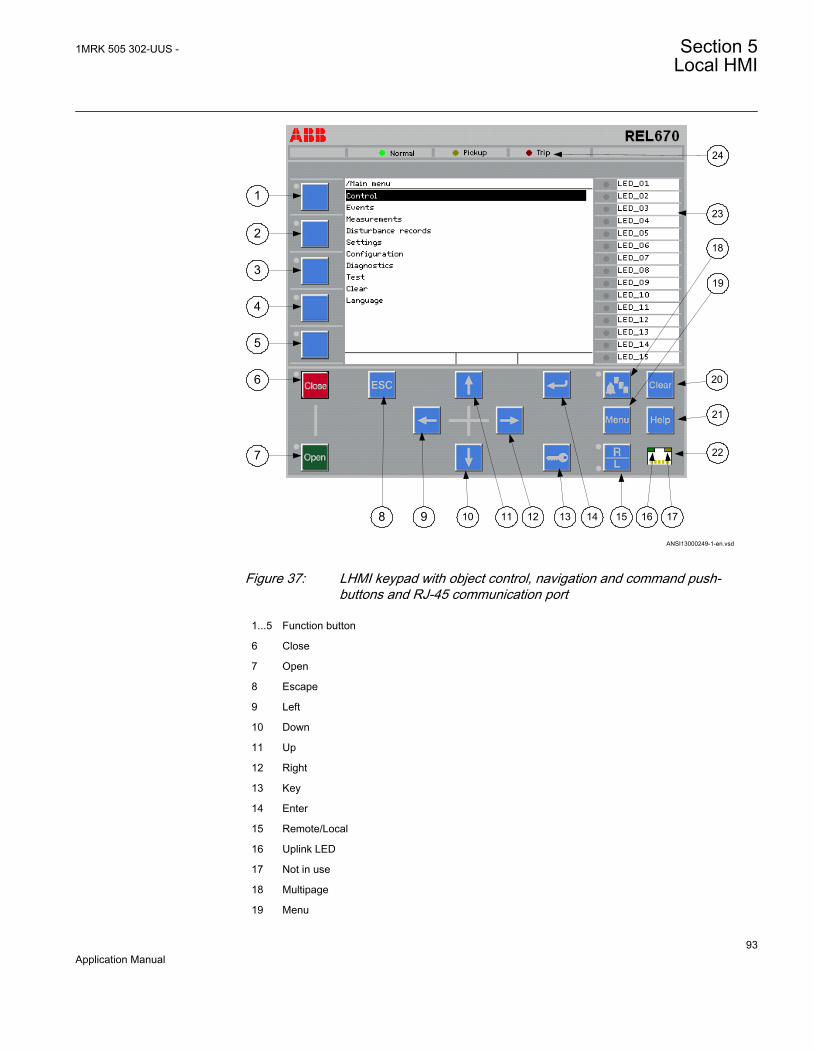
ANSI13000249-1-en.vsd
1
18
19
7
6
5
4
3
2
8
20
21
22
17161514131211109
23
24
GUID-C0B7E9D3-0FEB-4447-B3EB-218D3528B874 V1 EN
Figure 37: LHMI keypad with object control, navigation and command push-buttons and RJ-45 communication port
1...5 Function button
6 Close
7 Open
8 Escape
9 Left
10 Down
11 Up
12 Right
13 Key
14 Enter
15 Remote/Local
16 Uplink LED
17 Not in use
18 Multipage
19 Menu
1MRK 505 302-UUS - Section 5Local HMI
93Application Manual
20 Clear
21 Help
22 Communication port
23 Programmable alarm LEDs
24 Protection status LEDs
5.4 Local HMI functionality
5.4.1 Protection and alarm indication
Protection indicatorsThe protection indicator LEDs are Normal, Pickup and Trip.
Table 3: Normal LED (green)
LED state DescriptionOff Auxiliary supply voltage is disconnected.
On Normal operation.
Flashing Internal fault has occurred.
Table 4: PickUp LED (yellow)
LED state DescriptionOff Normal operation.
On A protection function has picked up and an indication message is displayed.The pick up indication is latching and must be reset via communication,LHMI or binary input on the LEDGEN component. To open the reset menuon the LHMI, press .
Flashing The IED is in test mode and protection functions are blocked, or theIEC61850 protocol is blocking one or more functions.The indication disappears when the IED is no longer in test mode andblocking is removed. The blocking of functions through the IEC61850protocol can be reset in Main menu/Test/Reset IEC61850 Mod. The yellowLED changes to either On or Off state depending on the state of operation.
Section 5 1MRK 505 302-UUS -Local HMI
94Application Manual
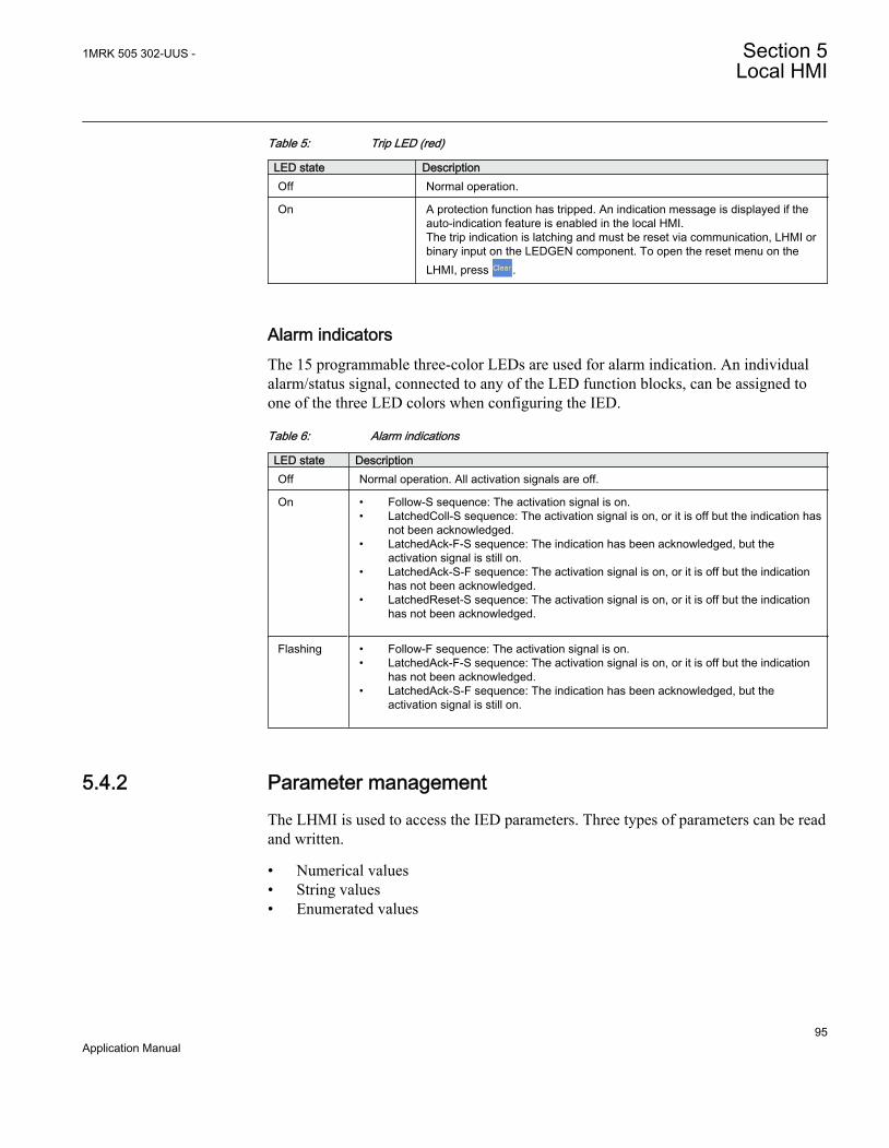
Table 5: Trip LED (red)
LED state DescriptionOff Normal operation.
On A protection function has tripped. An indication message is displayed if theauto-indication feature is enabled in the local HMI.The trip indication is latching and must be reset via communication, LHMI orbinary input on the LEDGEN component. To open the reset menu on theLHMI, press .
Alarm indicatorsThe 15 programmable three-color LEDs are used for alarm indication. An individualalarm/status signal, connected to any of the LED function blocks, can be assigned toone of the three LED colors when configuring the IED.
Table 6: Alarm indications
LED state DescriptionOff Normal operation. All activation signals are off.
On • Follow-S sequence: The activation signal is on.• LatchedColl-S sequence: The activation signal is on, or it is off but the indication has
not been acknowledged.• LatchedAck-F-S sequence: The indication has been acknowledged, but the
activation signal is still on.• LatchedAck-S-F sequence: The activation signal is on, or it is off but the indication
has not been acknowledged.• LatchedReset-S sequence: The activation signal is on, or it is off but the indication
has not been acknowledged.
Flashing • Follow-F sequence: The activation signal is on.• LatchedAck-F-S sequence: The activation signal is on, or it is off but the indication
has not been acknowledged.• LatchedAck-S-F sequence: The indication has been acknowledged, but the
activation signal is still on.
5.4.2 Parameter managementThe LHMI is used to access the IED parameters. Three types of parameters can be readand written.
• Numerical values• String values• Enumerated values
1MRK 505 302-UUS - Section 5Local HMI
95Application Manual
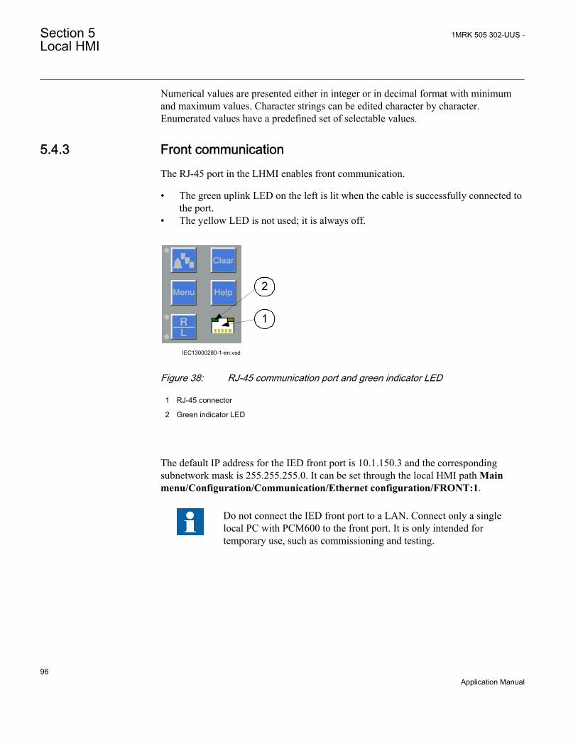
Numerical values are presented either in integer or in decimal format with minimumand maximum values. Character strings can be edited character by character.Enumerated values have a predefined set of selectable values.
5.4.3 Front communicationThe RJ-45 port in the LHMI enables front communication.
• The green uplink LED on the left is lit when the cable is successfully connected tothe port.
• The yellow LED is not used; it is always off.
IEC13000280-1-en.vsd
1
2
GUID-94AF2358-6905-4782-B37B-ACD3DCBF7F9C V1 EN
Figure 38: RJ-45 communication port and green indicator LED
1 RJ-45 connector
2 Green indicator LED
The default IP address for the IED front port is 10.1.150.3 and the correspondingsubnetwork mask is 255.255.255.0. It can be set through the local HMI path Mainmenu/Configuration/Communication/Ethernet configuration/FRONT:1.
Do not connect the IED front port to a LAN. Connect only a singlelocal PC with PCM600 to the front port. It is only intended fortemporary use, such as commissioning and testing.
Section 5 1MRK 505 302-UUS -Local HMI
96Application Manual

Section 6 Differential protection
6.1 Busbar differential protection
6.1.1 Identification
Busbar differential protection, 3-phase version
Function description IEC 61850identification
IEC 60617identification
ANSI/IEEE C37.2device number
Busbar differential protection, 2 zones,three phase/4 bays BUTPTRC 3Id/I
SYMBOL-JJ V1 EN
87B
Busbar differential protection, 2 zones,three phase/4 or 8 bays BTCZPDIF 3Id/I
SYMBOL-JJ V1 EN
87B
Busbar differential protection, 2 zones,three phase/4 or 8 bays BZNTPDIF_A 3Id/I
SYMBOL-JJ V1 EN
87B
Busbar differential protection, 2 zones,three phase/4 or 8 bays BZNTPDIF_B 3Id/I
SYMBOL-JJ V1 EN
87B
Busbar differential protection, 2 zones,three phase/4 or 8 bays BZITGGIO 3Id/I
SYMBOL-JJ V1 EN
87B
1MRK 505 302-UUS - Section 6Differential protection
97Application Manual

Busbar differential protection, 1-phase versionFunction description IEC 61850
identificationIEC 60617identification
ANSI/IEEE C37.2device number
Busbar differential protection, 2 zones,single phase/12 or 24 bays BUSPTRC 3Id/I
SYMBOL-JJ V1 EN
87B
Busbar differential protection, 2 zones,single phase/12 or 24 bays BCZSPDIF 3Id/I
SYMBOL-JJ V1 EN
87B
Busbar differential protection, 2 zones,single phase/12 or 24 bays BZNSPDIF_A 3Id/I
SYMBOL-JJ V1 EN
87B
Busbar differential protection, 2 zones,single phase/12 or 24 bays BZNSPDIF_B 3Id/I
SYMBOL-JJ V1 EN
87B
Busbar differential protection, 2 zones,single phase/12 or 24 bays BZISGGIO 3Id/I
SYMBOL-JJ V1 EN
87B
Status of primary switching object for Busbar protection zone selectionFunction description IEC 61850
identificationIEC 60617identification
ANSI/IEEE C37.2device number
Status of primary switching object forBusbar protection zone selection BDCGAPC - -
Section 6 1MRK 505 302-UUS -Differential protection
98Application Manual
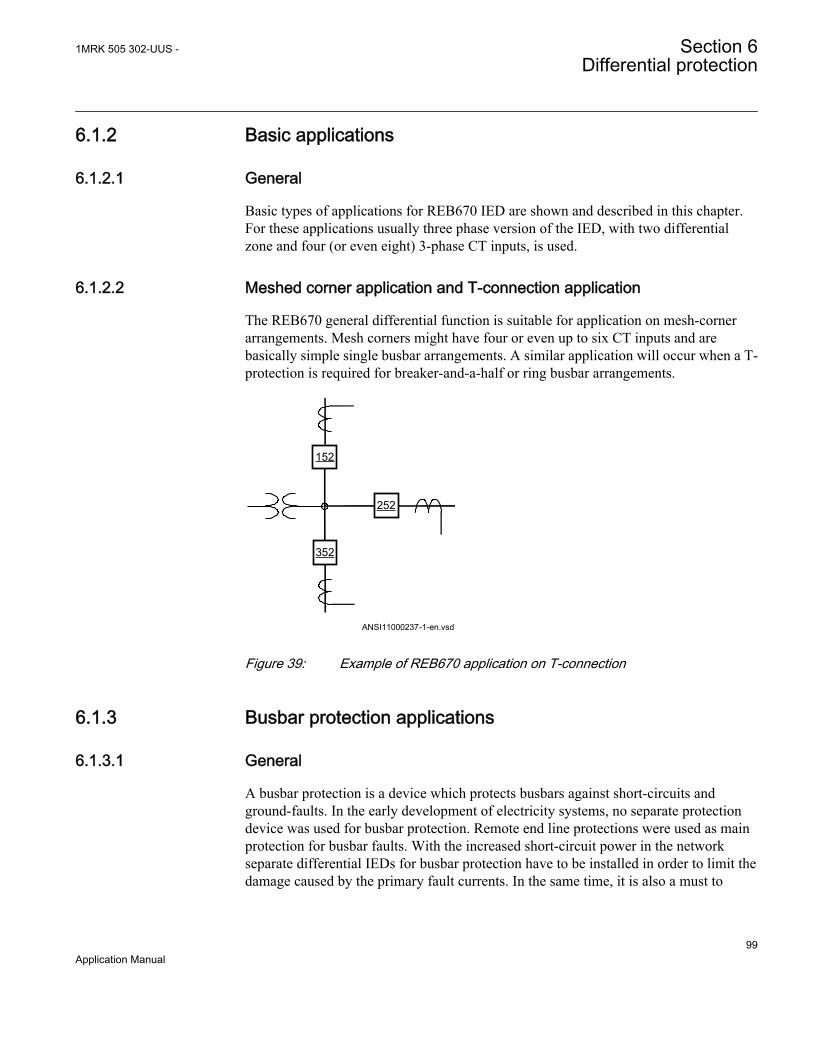
6.1.2 Basic applications
6.1.2.1 General
Basic types of applications for REB670 IED are shown and described in this chapter.For these applications usually three phase version of the IED, with two differentialzone and four (or even eight) 3-phase CT inputs, is used.
6.1.2.2 Meshed corner application and T-connection application
The REB670 general differential function is suitable for application on mesh-cornerarrangements. Mesh corners might have four or even up to six CT inputs and arebasically simple single busbar arrangements. A similar application will occur when a T-protection is required for breaker-and-a-half or ring busbar arrangements.
ANSI11000237-1-en.vsd
252
352
152
ANSI11000237 V1 EN
Figure 39: Example of REB670 application on T-connection
6.1.3 Busbar protection applications
6.1.3.1 General
A busbar protection is a device which protects busbars against short-circuits andground-faults. In the early development of electricity systems, no separate protectiondevice was used for busbar protection. Remote end line protections were used as mainprotection for busbar faults. With the increased short-circuit power in the networkseparate differential IEDs for busbar protection have to be installed in order to limit thedamage caused by the primary fault currents. In the same time, it is also a must to
1MRK 505 302-UUS - Section 6Differential protection
99Application Manual
secure the network stability, as a delayed tripping for busbar faults can also lead tonetwork instability, pole slip of near-by generators and even total system collapse.
For bus zone protection applications, it is extremely important to have good securitysince an unwanted operation might have severe consequences. The unwanted operationof the bus differential IED will have the similar effect from the operational point ofview as simultaneous faults on all power system elements connected to the bus. On theother hand, the IED has to be dependable as well. Failure to operate or even slowoperation of the differential IED, in case of an actual internal fault, can have seriousconsequences. Human injuries, power system blackout, transient instability orconsiderable damage to the surrounding substation equipment and the close-bygenerators are some of the possible outcomes.
Therefore, Busbar differential protection must fulfill the following requirements:
1. Must be absolutely stable during all external faults. External faults are much morecommon than internal faults. The magnitude of external faults can be equal to thestations maximum short circuit capacity. Heavy CT-saturation due to high DCcomponents and/or remanence at external faults must not lead to maloperation ofthe busbar differential protection. The security against misoperation must beextremely high due to the heavy impact on the overall network service.
2. Must have as short tripping time as possible in order to minimize the damage,minimize the danger and possible injury to the people who might be working inthe station at the moment of internal fault, and secure the network stability.
3. Must be able to detect and securely operate for internal faults even with heavy CTsaturation. The protection must also be sensitive enough to operate for minimumfault currents, which sometimes can be lower than the maximum load currents.
4. Must be able to selectively detect faults and trip only the faulty part of the busbarsystem.
5. Must be secure against maloperation due to auxiliary contact failure, possiblehuman mistakes and faults in the secondary circuits and so on.
6.1.3.2 Distinctive features of busbar protection schemes
A busbar protection scheme design, depends very much on the substation arrangement.Complexity of the scheme can drastically vary from station to station. Typicalapplications problems, for the most common busbar protection schemes, are describedin this chapter.
6.1.3.3 Differential protection
The basic concept for any differential IED is that the sum of all currents, which flow toand from the protection zone, must be equal to zero. If this is not the case, an internalfault has occurred. This is practically a direct use of well known Kirchhoffss first law.
Section 6 1MRK 505 302-UUS -Differential protection
100Application Manual

However, busbar differential IEDs do not measure directly the primary currents in thehigh voltage conductors, but the secondary currents of magnetic core currenttransformers (that is, CTs), which are installed in all high-voltage bays connected tothe busbar.
Therefore, the busbar differential IED is unique in this respect, that usually quite a fewCTs, often with very different ratios and classes, are connected to the same differentialprotection zone. Because the magnetic core current transformers are non-linearmeasuring devices, under high current conditions in the primary CT circuits theindividual secondary CT currents can be drastically different from the original primarycurrents. This is caused by CT saturation, a phenomenon that is well known toprotection engineers. During the time when any of the current transformer connected tothe differential IED is saturated, the sum of all CT secondary currents will not be equalto zero and the IED will measure false differential current. This phenomenon isespecially predominant for busbar differential protection applications, because it hasthe strong tendency to cause unwanted operation of the differential IED.
Remanence in the magnetic core of a current transformer is an additional factor, whichcan influence the secondary CT current. It can improve or reduce the capability of thecurrent transformer to properly transfer the primary current to the secondary side.However, the CT remanence is a random parameter and it is not possible in practice toprecisely predict it.
Another, and maybe less known, transient phenomenon appears in the CT secondarycircuit at the instant when a high primary current is interrupted. It is particularlydominant if the HV circuit breaker chops the primary current before its natural zerocrossing. This phenomenon is manifested as an exponentially decaying dc currentcomponent in the CT secondary circuit. This secondary dc current has nocorresponding primary current in the power system. The phenomenon can be simplyexplained as a discharge of the magnetic energy stored in the magnetic core of thecurrent transformer during the high primary current condition. Depending on the typeand design of the current transformer this discharging current can have a time constantin the order of a hundred milliseconds.
Consequently, all these phenomena have to be considered during the design stage of abusbar differential IED in order to prevent the unwanted operation of the IED duringexternal fault conditions.
The analog generation of the busbar differential IEDs (that is, KA2, 87B, RADHA,RADSS, REB 103) generally solves all these problems caused by the CT non-linearcharacteristics by using the galvanic connection between the secondary circuits of allCTs connected to the protected zone. These IEDs are designed in such a way that thecurrent distribution through the IED differential branch during all transient conditionscaused by non-linearity of the CTs will not cause the unwanted operation of thedifferential IED. In order to obtain the required secondary CT current distribution, the
1MRK 505 302-UUS - Section 6Differential protection
101Application Manual
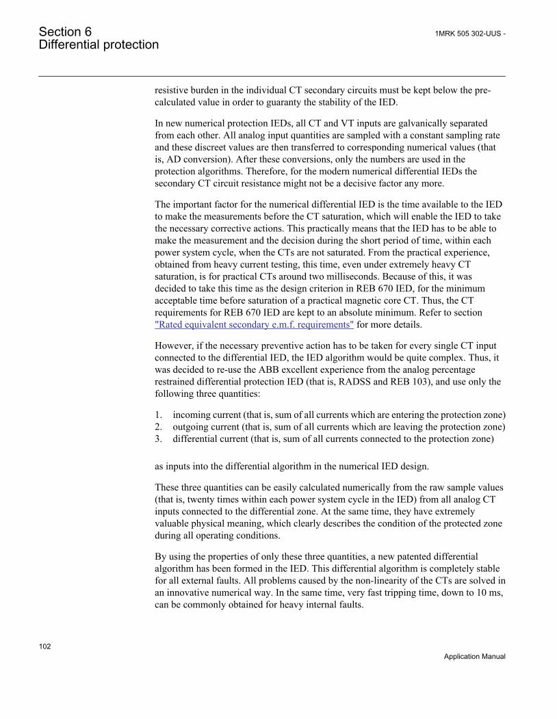
resistive burden in the individual CT secondary circuits must be kept below the pre-calculated value in order to guaranty the stability of the IED.
In new numerical protection IEDs, all CT and VT inputs are galvanically separatedfrom each other. All analog input quantities are sampled with a constant sampling rateand these discreet values are then transferred to corresponding numerical values (thatis, AD conversion). After these conversions, only the numbers are used in theprotection algorithms. Therefore, for the modern numerical differential IEDs thesecondary CT circuit resistance might not be a decisive factor any more.
The important factor for the numerical differential IED is the time available to the IEDto make the measurements before the CT saturation, which will enable the IED to takethe necessary corrective actions. This practically means that the IED has to be able tomake the measurement and the decision during the short period of time, within eachpower system cycle, when the CTs are not saturated. From the practical experience,obtained from heavy current testing, this time, even under extremely heavy CTsaturation, is for practical CTs around two milliseconds. Because of this, it wasdecided to take this time as the design criterion in REB 670 IED, for the minimumacceptable time before saturation of a practical magnetic core CT. Thus, the CTrequirements for REB 670 IED are kept to an absolute minimum. Refer to section"Rated equivalent secondary e.m.f. requirements" for more details.
However, if the necessary preventive action has to be taken for every single CT inputconnected to the differential IED, the IED algorithm would be quite complex. Thus, itwas decided to re-use the ABB excellent experience from the analog percentagerestrained differential protection IED (that is, RADSS and REB 103), and use only thefollowing three quantities:
1. incoming current (that is, sum of all currents which are entering the protection zone)2. outgoing current (that is, sum of all currents which are leaving the protection zone)3. differential current (that is, sum of all currents connected to the protection zone)
as inputs into the differential algorithm in the numerical IED design.
These three quantities can be easily calculated numerically from the raw sample values(that is, twenty times within each power system cycle in the IED) from all analog CTinputs connected to the differential zone. At the same time, they have extremelyvaluable physical meaning, which clearly describes the condition of the protected zoneduring all operating conditions.
By using the properties of only these three quantities, a new patented differentialalgorithm has been formed in the IED. This differential algorithm is completely stablefor all external faults. All problems caused by the non-linearity of the CTs are solved inan innovative numerical way. In the same time, very fast tripping time, down to 10 ms,can be commonly obtained for heavy internal faults.
Section 6 1MRK 505 302-UUS -Differential protection
102Application Manual

Please refer to the technical reference manual for more details about the workingprinciples of the Differential Function algorithm.
6.1.3.4 Zone selection (CT switching)
The so-called CT switching (that is, zone selection) is required in situation when oneparticular circuit (that is, bay) can be connected to different busbars by individualdisconnectors. Typical example is a station with double busbars with or withouttransfer bus as shown in figure 68 and figure 61, where any feeder bay can beconnected to any of the two buses. In such cases the status of all busbar disconnectorsand all transfer disconnectors shall be given to the busbar protection.
Traditionally, the CT switching has been done in CT secondary circuits. However, withREB670 this is not the case. All necessary zone selection (that is, CT switching) isdone in software. Therefore, the CT secondary circuits are always intact and withoutany auxiliary relay contacts.
To provide proper zone selection (that is, busbar replica) the position information fromall relevant primary switches (that is, disconnectors and/or circuit breakers) must begiven to the IED. This is typically done by connecting two auxiliary contacts (that is,normaly open and normaly closed aux contacts) from each primary switch to the IEDbinary inputs (that is, optocouplers). In REB670 configuration one SwitchStatusfunction block shall be associated with each primary switching device. This block isthen used internally to derive the primary object status and then pass this informationto the busbar protection internal Zone Selection logic.
6.1.3.5 Auxiliary contact requirement and evaluation
Auxiliary contact requirements for disconnectors and circuit breakersThe position of the primary switching object is typically obtained via two auxiliarycontacts of the primary apparatus. The first auxiliary contact indicates that primarydevice is closed. In protection literature it is called by different names as stated below:
• Normally open auxiliary contact• “a” contact (that is, 52a)• “closed”
The second auxiliary contact indicates that primary device is open. In protectionliterature it is called by different names as stated below:
• Normally closed auxiliary contact• “b” contact (that is, 52b)• “open”
1MRK 505 302-UUS - Section 6Differential protection
103Application Manual

Typically both contacts are used to provide position indication and supervision forbusbar protection.
6.1.3.6 Minimum contact requirements
The minimum requirement for the busbar replica is the record of the disconnectorposition by using just one auxiliary contact, either NO or NC type. However recordinga pair of auxiliary contacts, representing the OPEN and CLOSE position, offeradditional features which can improve the reliability of the bus replica includingsupervision possibilities.
6.1.3.7 Auxiliary contact evaluation logic
Two logic schemes can be found.
Scheme1_RADSS "If not OPEN then CLOSED"As the name of the scheme suggests, only when the auxiliary contacts signal cleanopen position ("normally open auxiliary (NO) contact input" = inactive and "normallyclosed auxiliary (NC) contact input" = active), the disconnector is taken to be open. Forall other signal combinations the disconnector is considered to be closed. This schemedoes not pose any special requirements to the auxiliary contact timing. Only thedisconnector NC contact must open before the disconnector main contact is withinarcing distance. The time during which the OPEN and CLOSED signal inputs disagree(that is, both binary inputs are active or both are inactive) is monitored by the isolatorsupervision function. The maximum time allowed before an alarm is given can be setaccording to the disconnector timing.
Scheme2_INX "Closed or open if clear indication available otherwiselast position saved"As the name of the scheme suggests, only when the auxiliary contacts signal cleanOPEN or clean CLOSED position disconnector is considered to be open respectivelyclosed. However this poses the stringent requirements on the auxiliary contacts that theCLOSED signal must become active a certain time (>150 ms) before current startsflowing for example, through arcing. Otherwise this current will not be taken intoaccount in the busbar protection and this can result in a maloperation. Therefore, goodtiming of two auxiliary contacts is definitely required.
The time during which the OPEN and CLOSED signals disagree (that is, both binaryinputs are active or both are inactive) is monitored by the isolator supervision functionfor both of the above two schemes. The maximum time allowed before an alarm isgiven can be set according to the disconnector timing.
Table 7 and the following two figures summarize the properties of these two schemes.
Section 6 1MRK 505 302-UUS -Differential protection
104Application Manual

Table 7: Treatment of primary object auxiliary contact status within BBP in REB670
Primary equipment Status in busbar protection Alarm facilityNormallyOpenauxiliarycontact status(“closed” or“a” contact)
NormallyClosedauxiliarycontact status(“open” or “b”contact)
when“Scheme 1RADSS”is selected
when“Scheme 2INX”is selected
Alarm aftersettable timedelay
Information visible onlocal HMI
open open closed Lastpositionsaved
yes intermediate_00
open
closed open open no open
closed
open closed closed no closed
closed closed closed closed yes badState_11
BBP
input „closed“
input „open“
N.O.
N.C.
10
10
10
closedopen
arcing possible
currentassignment
1) 1)
1) disconnector supervision running
en06000084.vsdIEC06000084 V1 EN
Figure 40: Scheme_1 RADSS
1MRK 505 302-UUS - Section 6Differential protection
105Application Manual
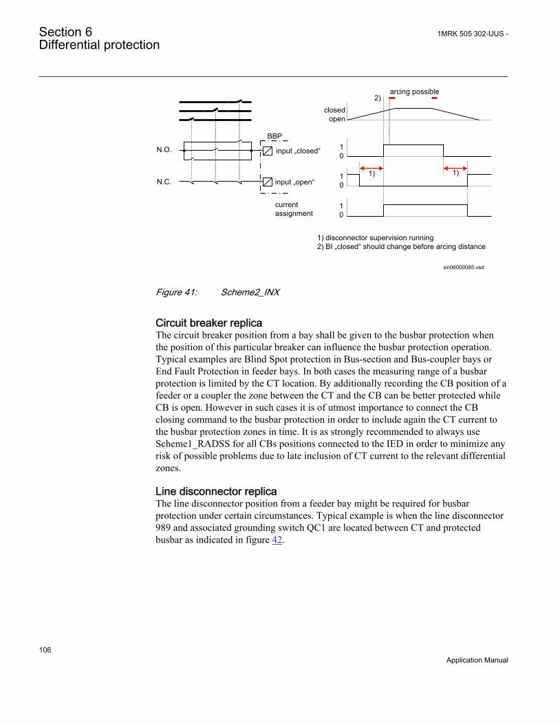
BBP
input „closed“
input „open“
N.O.
N.C.
10
10
10
closedopen
arcing possible
currentassignment
2)
1) 1)
1) disconnector supervision running2) BI „closed“ should change before arcing distance
en06000085.vsdIEC06000085 V1 EN
Figure 41: Scheme2_INX
Circuit breaker replicaThe circuit breaker position from a bay shall be given to the busbar protection whenthe position of this particular breaker can influence the busbar protection operation.Typical examples are Blind Spot protection in Bus-section and Bus-coupler bays orEnd Fault Protection in feeder bays. In both cases the measuring range of a busbarprotection is limited by the CT location. By additionally recording the CB position of afeeder or a coupler the zone between the CT and the CB can be better protected whileCB is open. However in such cases it is of utmost importance to connect the CBclosing command to the busbar protection in order to include again the CT current tothe busbar protection zones in time. It is as strongly recommended to always useScheme1_RADSS for all CBs positions connected to the IED in order to minimize anyrisk of possible problems due to late inclusion of CT current to the relevant differentialzones.
Line disconnector replicaThe line disconnector position from a feeder bay might be required for busbarprotection under certain circumstances. Typical example is when the line disconnector989 and associated grounding switch QC1 are located between CT and protectedbusbar as indicated in figure 42.
Section 6 1MRK 505 302-UUS -Differential protection
106Application Manual

189
ZA
ZB289
989 189G
en06000086_ansi.vsd
152
ANSI06000086 V1 EN
Figure 42: Feeder bay layout when line disconnector position might be requiredfor busbar protection
Such feeder set-up can be often found in GIS stations where cable CTs are used forbusbar protection. If in such feeder the line disconnector 989 is open and thenimmediately the grounding switch 189G is closed before the busbar disconnectors189G & 289 are open there is a danger to get current unbalance into the zonedifferential measurement under following circumstances:
• In case of parallel lines zero sequence mutual coupling can induce zero sequencecurrent into the grounded line especially during externalground-faults.
• In case of cable feeder the stored energy in the cable will be discharged throughthe grounding switch at the moment of its closing.
In order to avoid such problems for busbar protection the status of line disconnectorcan be monitored by busbar protection and CT measurement can be disconnected fromboth differential zones as soon line disconnector is open. Similar functionality can beobtained by instead monitoring the position of feeder breaker 152. In such case thebreaker closing signal shall be connected to busbar protection as well.
6.1.3.8 Zone selection features
The IED offers an extremely effective solution for stations where zone selection (thatis, CT switching) is required. This is possible due to the software facility, which givesfull and easy control over all CT inputs connected to the IED. The philosophy is toallow every CT input to be individually controlled by a setting parameter. Thisparameter called ZoneSel can be individually configured for every CT input. Thisparameter, for every bay, can be set to only one of the following five alternatives:
1MRK 505 302-UUS - Section 6Differential protection
107Application Manual

1. FIXEDtoZA2. FIXEDtoZB3. FIXEDtoZA&-ZB4. CtrlIncludes5. CtrlExcludes
If for a particular CT input setting parameter ZoneSel is set to FIXEDtoZA, then thisCT input will be only included to the differential zone A. This setting is typically usedfor simple single zone application such as: single busbar staions, breaker-and-a-halfstations or double breaker stations.
If for a particular CT input setting parameter ZoneSel is set to FIXEDtoZB, then thisCT input will be only included to the differential zone B. This setting is typically usedfor applications such as: breaker-and-a-half stations or double breaker stations.
If for a particular CT input setting parameter ZoneSel is set to FIXEDtoZA&-ZB, thenthis CT input will be included to the differential zone A, but its inverted current valuewill be as well included to the differential zone B. This setting is typically used for buscoupler or bus section bays when only one current transformer is available see figure44.
If for a particular CT input setting parameter ZoneSel is set to Ctrl_Includes, then thisCT input will be:
• included to the differential zone A when input signal CTRLZA on correspondingbay block is given logical value one and it will be excluded from the differentialzone A when input signal CTRLZA on corresponding bay block is given logicalvalue zero.
• included to the differential zone B when input signal CTRLZB on correspondingbay block is given logical value one and it will be excluded from the differentialzone B when input signal CTRLZB on corresponding bay block is given logicalvalue zero.
This setting is typically used for feeder bays in double busbar stations in order to formproper busbar disconnector replica. It is especially suitable when normally open andnormally closed (that is, a and b) auxiliary contacts from the busbar disconnectors areavailable to the IED.
If for a particular CT input setting parameter ZoneSel is set to Ctrl_Excludes, then thisCT input will be:
• excluded from the differential zone A when input signal CTRLZA oncorresponding bay block is given logical value one and it will be included to the
Section 6 1MRK 505 302-UUS -Differential protection
108Application Manual
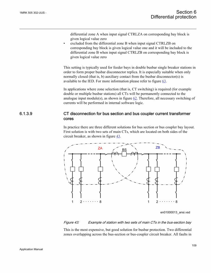
differential zone A when input signal CTRLZA on corresponding bay block isgiven logical value zero
• excluded from the differential zone B when input signal CTRLZB oncorresponding bay block is given logical value one and it will be included to thedifferential zone B when input signal CTRLZB on corresponding bay block isgiven logical value zero
This setting is typically used for feeder bays in double busbar single breaker stations inorder to form proper busbar disconnector replica. It is especially suitable when onlynormally closed (that is, b) auxiliary contact from the busbar disconnector(s) isavailable to the IED. For more information please refer to figure 63.
In applications where zone selection (that is, CT switching) is required (for exampledouble or multiple busbar stations) all CTs will be permanently connected to theanalogue input module(s), as shown in figure 62. Therefore, all necessary switching ofcurrents will be performed in internal software logic.
6.1.3.9 CT disconnection for bus section and bus coupler current transformercores
In practice there are three different solutions for bus section or bus coupler bay layout.First solution is with two sets of main CTs, which are located on both sides of thecircuit breaker, as shown in figure 43.
ZA
21 8
ZB
21 8
BS
en01000013_ansi.vsdANSI01000013 V1 EN
Figure 43: Example of station with two sets of main CTs in the bus-section bay
This is the most expensive, but good solution for busbar protection. Two differentialzones overlapping across the bus-section or bus-coupler circuit breaker. All faults in
1MRK 505 302-UUS - Section 6Differential protection
109Application Manual

the overlapping zone will be instantly tripped by both zones irrespective of the section/coupler circuit breaker status. However with modern busbar protection it is possible todisconnect both CTs from the relevant zones when the bus-section or bus-couplercircuit breaker is open. This will insure that if internal fault happen, in the overlappingzone, while breaker is open, only the faulty zone will be tripped while other busbarsection will remain in service. However, due to low probability of such faulthappening, while the breaker is open, such special considerations are typically notincluded in the busbar protection scheme for this type of stations. In such applicationthe bus section or bus coupler current transformers shall be wired just to two separatecurrent input of the IED. Then in the parameter setting tool (PST) for thecorresponding bays the parameter ZoneSel shall be set to FIXEDtoZA in one bay andFIXEDtoZB in another bay. This will insure that these currents are given to bothdifferential zones.
When live tank circuit breakers are used, owing to the high cost of the HV currenttransformer often only one current transformer is available in bus-section or bus-coupler bay. The suggested solution in such applications is shown in figure 44.
ZA
21 8
ZB
21 8
Blind Zone
en01000014_ansi.vsdANSI01000014 V1 EN
Figure 44: Example of station with just one main CT in the bus-section bay
For this type of solution just one main CT is located on only one side of the circuitbreaker. Thus, there is no zone overlapping across the section/coupler circuit breaker asshown in figure 43. A blind spot exists between the current transformer and the circuitbreaker in the bus section or bus-coupler bay as shown in figure 44.
For an internal fault in the blind spot, the differential zone ZA will unnecessarilyoperate and open the bus section breaker and all other feeder breakers associated with
Section 6 1MRK 505 302-UUS -Differential protection
110Application Manual
it. Nevertheless the fault will still exists on other busbar section, but it is outside thecurrent transformer in the bus section bay and hence outside the zone ZB ( that is, it isexternal fault for zone ZB). Similar problem will also exist if section/coupler circuitbreaker was open before the internal fault in the blind zone. Therefore, the busbarprotection scheme does not protect the complete busbar.
In order to improve the busbar protection scheme with this type of station layout, it isoften required to disconnect the bus-section or bus-coupler CT from the twodifferential zones as soon as the bus-section or bus-coupler circuit breaker is opened.This arrangement can be easily achieved within the IED. In such application the bussection or bus coupler current transformer shall be wired just to one current input of theIED. Then in the Parameter Setting tool for the corresponding bay parameter ZoneSelshall be set to FIXEDtoZA&-ZB. This will insure that this current is given to bothdifferential zones. In order to disconnect this current from both zones, when the coupler/section breaker is open additional logic as shown in figure 45 have to be done in theconfiguration. The following two binary inputs are at least necessary in order toguaranty proper operation of such logic:
• Normally closed contact of the bus section or bus coupler circuit breaker
• Signal from the bus section or bus coupler circuit breaker closing circuit thatsomebody wants to close the breaker
This solution does not depend on contact timing between the main contacts andauxiliary contact of the circuit breaker. It directly follows the philosophy used forRADSS/REB 103 schemes used for similar applications before. Principle connectionbetween the bus-coupler CB normally closed auxiliary contact (b-contact), REB670and internal configuration logic, as shown in figure 45
1MRK 505 302-UUS - Section 6Differential protection
111Application Manual

en06000155_ansi.vsd
Zone AZone B
Bus-Coupler Bay
REB 670
CTRLZACTRLZB
TRIPCONNZACONNZB
Bxxx
I3PB1
BLKTR
TRZONETRBAY
BBP & BFP trip command to Bus-Coupler breaker
BOM
A/D
Parameter ZoneSel must be set to "FixedToZA&-ZB"
tZeroCurrent=150ms
Other Equipment
CT Input TRM
External or InternalBus-Coupler BFP
Backup Trip Command
Bus-Coupler Backup OC Trip
189
289
BI1
ZEROCUR
BIMCB Closing Signal
tt=1s
b 152
AND
OR
ANSI06000155 V1 EN
Figure 45: Bus coupler bay with one CT and b aux. contact only from CB
This scheme will disconnect the section/coupler CTs after about 80 ms (pre-set timeunder parameter setting tZeroCurrent in the relevant bay function block) from themoment of opening of the section/coupler CB ( that is, from the moment whenauxiliary b contact makes). Nevertheless this time delay is absolutely necessary inorder to prevent racing between the opening of the main breaker contact anddisconnection of the CT from the differential zones. This scheme will as welldisconnect the CT in case of the operation of any of the two internal differential zonesused in the scheme. This will secure the delayed (about 150 ms) clearing and trippingof the internal fault within the blind zone even in case of section/coupler circuit breakerfailure during such fault. This facility will improve the performance of the busbarprotection scheme when one CT is located on only one side of the bus-section / bus-coupler circuit breaker.
With GIS or live tank circuit breakers, owing to high cost of HV CT installations,sometimes no current transformers are available in bus-section or bus-coupler bay.This is the third solution shown in figure 46
Section 6 1MRK 505 302-UUS -Differential protection
112Application Manual
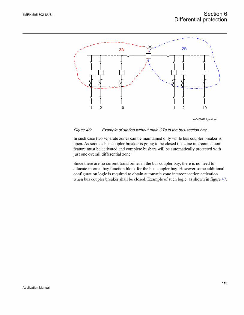
en04000283_ansi.vsd
ZA
21 10
ZB
21 10
BS
ANSI04000283 V1 EN
Figure 46: Example of station without main CTs in the bus-section bay
In such case two separate zones can be maintained only while bus coupler breaker isopen. As soon as bus coupler breaker is going to be closed the zone interconnectionfeature must be activated and complete busbars will be automatically protected withjust one overall differential zone.
Since there are no current transformer in the bus coupler bay, there is no need toallocate internal bay function block for the bus coupler bay. However some additionalconfiguration logic is required to obtain automatic zone interconnection activationwhen bus coupler breaker shall be closed. Example of such logic, as shown in figure 47.
1MRK 505 302-UUS - Section 6Differential protection
113Application Manual
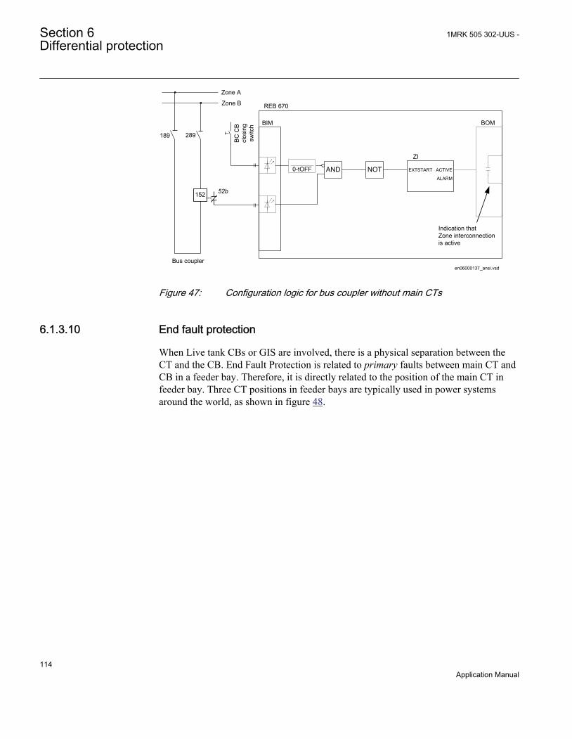
en06000137_ansi.vsd
Zone A
Zone B
ZI
ACTIVE
BOMBIM
REB 670
Bus coupler
EXTSTART
ALARM
Indication that Zone interconnectionis active
BC
CB
clos
ing
switc
h
189 289
152 52b
AND NOT0-tOFF
ANSI06000137 V1 EN
Figure 47: Configuration logic for bus coupler without main CTs
6.1.3.10 End fault protection
When Live tank CBs or GIS are involved, there is a physical separation between theCT and the CB. End Fault Protection is related to primary faults between main CT andCB in a feeder bay. Therefore, it is directly related to the position of the main CT infeeder bay. Three CT positions in feeder bays are typically used in power systemsaround the world, as shown in figure 48.
Section 6 1MRK 505 302-UUS -Differential protection
114Application Manual

en06000138_ansi.vsd
BI1
BI1Busbar
Protection
Feeder Protection BI1
Busbar Protection
Feeder Protection
BI1
Busbar Protection
Feeder Protection
A B
1
C
1152152 152
ANSI06000138 V1 EN
Figure 48: Typical CT locations in a feeder bay
where:
A = two CTs are available one on each side of the feeder circuit breaker
B = one CT is available on the line side of the feeder circuit breaker
C = one CT is available on the bus side of the feeder circuit breaker
1 = End fault region
In figure 48, /A where two CTs are available in a feeder bay the end fault protection isnot an issue. The busbar and feeder protection zones overlap across feeder circuitbreaker and all faults between these two CTs will be instantly detected and tripped byboth protection schemes. As a consequence of such fault both busbar and feeder will bedisconnected from the power system.
In figure 48/B where one CT is available on the line side of the feeder circuit breakerthe primary fault between CT and CB will cause certain problems. Typically such faultwill be detected and tripped by busbar protection. However to completely clear suchfault the remote feeder end CB must be tripped as well. It shall be noted that for thefeeder protection such fault will be either a reverse fault (that is, distance protectionused for feeder protection) or external fault (that is, line/transformer differentialprotection used for feeder protection).
In figure 48/C where one CT is available on the bus side of the feeder circuit breakerthe primary fault between CT and CB will cause problem as well. Typically such faultwill be detected and tripped by feeder protection. However, to completely clear suchfault the associated busbar section must be tripped as well. It shall be noted that thebusbar differential protection will classify such fault as external and without anyadditional measures the busbar protection will remain stable.
For better understanding end fault protection applications within busbar protection, thefigure 49 is used.
1MRK 505 302-UUS - Section 6Differential protection
115Application Manual

ZA
xx06000139_ansi.vsd
4
3
1
2
152 152 152 152
ANSI06000139 V1 EN
Figure 49: Busbar protection measuring and fault clearing boundaries
where:
1 is Busbar Protection measuring boundary determined by feeder CT locations
2 is Busbar Protection internal fault clearing boundary determined by feeder CB locations
3 is End fault region for feeders as shown in figure 48/B
4 is End fault region for feeders as shown in figure 48/C
In figure 49 single busbar station is shown. Two feeders on the left-hand side have CTson the line side of the breaker. The two feeders on the right-hand side of the busbarhave CTs on the busbar side of the breaker. It is assumed that busbar protection isconnected to all four set of CTs in this station.
Due to CT location in feeder bays, busbar protection will detect all primary faultslocated within measuring boundary determined by CT locations, see figure 49.However its operation will only completely clear faults within clearing boundarydetermined by CB locations as shown in figure 49. Obviously, the primary faults in-between these two boundaries do pose certain practical problems.
First of all it shall be noted that there is no ideal solution for faults within end zoneregion in a feeder bay when the feeder breaker is closed. Such faults, within end faultregion, will be then cleared with additional time delay either by operation of localbackup protection (that is, feeder circuit breaker failure protection) or by operation ofremote backup protection (that is, remote ends zone 2 distance protection).
However, the overall busbar protection behavior can be improved for primary faultswithin end fault regions, when feeder breaker is open. Under such circumstances thefollowing actions can be taken:
Section 6 1MRK 505 302-UUS -Differential protection
116Application Manual

• For feeders with CT on the line side of the circuit breaker (that is, two feeders onthe left-hand side in figure 49), the current measurement can be disconnected fromthe busbar protection zone some time after feeder CB opening (for example, 400ms for transformer and cable feeders or longest autoreclosing dead time +300 msfor overhead line feeders). At the same time, appropriately set and fast (that is,typically 40 ms time delayed) overcurrent protection shall be enabled to detectfault within end fault region. Any operation of this overcurrent protection shallonly issue inter-trip command to the remote feeder end CB. Such overcurrentprotection is often called end fault protection in relay literature. It shall be notedthat at the same time busbar protection will remain stable (that is, selective) forsuch fault.
• For feeders with CT on the bus side of the circuit breaker (that is, two feeders onthe right-hand side in figure 49), the current measurement can be disconnectedfrom the busbar protection zone some time after feeder CB opening (that is, after400 ms). This measure will insure fast busbar protection tripping for faults withinend fault region in that feeder bay, while feeder CB is open.
However, it shall be noted that in order to utilize end fault protection feeder circuitbreaker status and its closing command must be connected to the binary inputs ofbusbar protection scheme in order to be available for Zone Selection logic. Please referto Zone Selection section for more info.
End fault protection logic can be easily done with help of graphical configuration tool.One stage (that is, 4th stage) from optionally available overcurrent protection can beused as dedicated end fault protection for feeders with CT on the line side of the CB.
End fault protection is here explained for simple single busbar station. However thesame principles are applicable to almost all other station layouts. However, undercertain circumstances, for stations with a transfer bus more extensive logic for end faultprotection implementation might be required.
6.1.3.11 Zone interconnection (Load transfer)
In double busbar stations or double busbar with transfer bus stations it is commonrequirement to use the possibility of zone interconnection of load current in any feederbay from one busbar to the other. The sequence of operation during zoneinterconnection is normally as the following:
• bus coupler bay is closed (that is, CB and both disconnectors).• feeder bay busbar disconnector to the busbar not already in service is then closed.
The switchgear interlocking system shall allow this only when the bus couplerbreaker is already closed. Depending on the thermal capacity of the feeder busbardisconnectors (189 and 289) the opening of the bus coupler circuit breaker is
1MRK 505 302-UUS - Section 6Differential protection
117Application Manual

sometimes interlocked while both busbar disconnectors within one of the feederbays are closed.
• opening of the feeder bay busbar disconnector originally closed. The load is nowtransferred from one to other bus.
• opening of bus coupler CB.
The zone interconnection has to be taken into consideration for the busbar differentialprotection scheme, as the two busbar zones are interconnected together via twodisconnectors. The primary current split between the two busbars is not known and thetwo separate measuring zones cannot be maintained.
In conventional, analog busbar protection systems the solutions have been to, byextensive zone switching IEDs, disconnect one zone (normally zone B) and to connectall feeders to other zone (normally zone A). At the same time the current from the bus-coupler bay, which just circulates between two zones, must be disconnected from themeasuring differential zone.
Similar situation regarding busbar protection can occur between two single busbarsections interconnected via sectionalizing disconnector, as shown in figure 54. Whensectionalizer is closed then two separate protection zones becomes one and busbarprotection must be able to dynamically handle this.
Due to the numerical design the IED can manage this situation in an elegant and simpleway. Internal feature called ZoneInterconnection will be used to handle both situations.This feature can be activated either externally via binary input or derived internally bybuilt-in logic. Internally, this “zone switching” feature will be activated if the followingconditions are met:
• bays have parameter ZoneSel set to either CtrlInclude or CtrlExcludes• internal zone selection logic concludes that this particular bay shall be
simultaneously connected to both internal differential zones
This situation only means that for this particular bay both busbar disconnectors areclosed and therefore zone interconnection switching is happening in the station.
When zone switching feature is activated inside the IED, each individual bay currentwill behave in the predetermined way as dictated by a parameter settingZoneSwitching. This parameter, for every bay, can be set to only one of the followingthree alternatives
• ForceOut• ForceIn• Conditionally
Section 6 1MRK 505 302-UUS -Differential protection
118Application Manual

If for a particular CT input setting parameter ZoneSwitching is set to ForceOut, thenthis CT input will be disconnected from both the differential zones, regardless of anyother set value or active binary input, while zone switching feature is active within theIED. This setting is typically used for bus coupler bay in double busbar stations.
If for a particular CT input setting parameter ZoneSwitching is set to ForceIn, then thisCT input will be connected to both the differential zones, regardless of any other setvalue or active binary input, while zone switching feature is active within the IED. Thissetting is typically used for all feeders bay in a station with two single zoneinterconnected by a sectionalizing disconnector.
If for a particular CT input setting parameter ZoneSwitching is set to Conditionally,then this CT input will be connected to both the differential zones only if it wasincluded to any of the two zones for 2ms before the zone switching feature wasactivated. This setting is typically used for all feeders bay in double busbar stations.With this setting all feeder bays, which were not connected to any of the two zonesbefore the zone interconnection activation (that is, out for scheduled maintenance), willnot either be included during zone interconnection.
This practically means that for double busbar station, when zone switching feature isactive, all feeder bays will be connected to both differential zones, while bus couplerCT will be disconnected from both zones. In this way simple but effective solution isformed. It is as well important to notice that all necessary changes in the individual baytripping arrangements will be automatically performed within the internal logic.
A dedicated binary signal will be immediately activated in the internal logic when zoneinterconnection feature is activated. If this feature is active longer than the pre-set timeseparate alarm binary signal is activated, in order to alarm the station personnel aboutsuch operating conditions. ZoneInterconnection feature can be disabled by a parametersetting for substation arrangements where it is not required that is, single busbarstations, breaker-and-a-half stations and so on.
Discriminating zones (that is, Zone A and Zone B) in the IED includes a sensitiveoperational level. This sensitive operational level is designed to be able to detectbusbar ground faults in low impedance edgrounded power systems (that is, powersystems where the ground-fault current is limited to a certain level, typically between300 A and 2000 A by neutral point reactor or resistor) or for some other specialapplications where increased sensitivity is required. Operation and operatingcharacteristic of the sensitive differential protection can be set independently from theoperating characteristic of the main differential protection. The sensitive differentiallevel is blocked as soon as the total incoming current exceeds the pre-set level. Byappropriate setting then it can be insured that this sensitive level is blocked for externalphase-to-phase or three-phase faults, which can cause CT saturation. Comparisonbetween these two characteristics is shown in figure 50.
1MRK 505 302-UUS - Section 6Differential protection
119Application Manual

Differential protectionoperation characteristic
Operateregion
Diff Oper LevelI d
[Prim
ary
Amps
]
Iin [Primary Amps]
s=0.53
I d=I in
Sensitivedifferentialprotection
en06000142.vsd
Sensitive Oper Level Sens Iin Block
IEC06000142 V1 EN
Figure 50: Differential protection operation characteristic
Additionally the sensitive differential protection can be time delayed and it must beexternally enabled by a binary signal (that is, from external open delta VT overvoltagerelay or power transformer neutral point overcurrent relay).
The setting parameters for the check zone are set via the local HMI or PCM600.
Such check zone is included in the IED. By a parameter setting CheckZoneSel =NotConnected/Connected can be decided, individually for every bay, if it shall beconnected to the check zone or not. This setting is available in bay function block.
For every zone there is a setting parameter CheckZoneSup, which can be set to Enabledor Disabled. This setting parameter determines if the individual zone shall besupervised or not by a check zone. This setting is available in both Zone functions.Finally the check zone shall be enabled (that is, setting parameter Operation shall beset to Enabled) in order to fully enable the check zone. Operating characteristics for thecheck zone can be set independently from the two discriminating zones.
However, it is to be observed that the check zone has slightly different operatingcharacteristic from the usual discriminating zones. For the check zone the resultantoutgoing current is used as stabilizing current instead of total incoming current in orderto guarantee the check zone operation for all possible operating conditions in thestation. The check zone operating characteristic is shown in figure 51:
Section 6 1MRK 505 302-UUS -Differential protection
120Application Manual
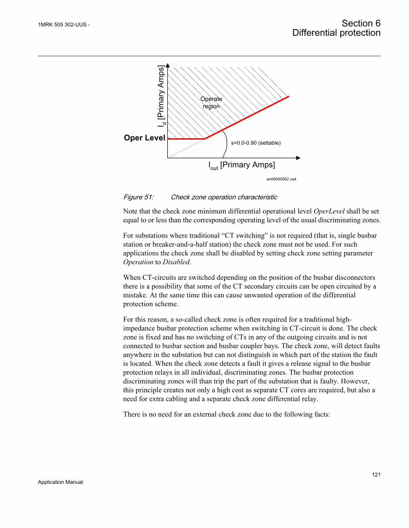
en06000062.vsd
Oper Levels=0.0-0.90 (settable)
Iout [Primary Amps]I d [
Prim
ary
Am
ps]
Operateregion
IEC06000062 V1 EN
Figure 51: Check zone operation characteristic
Note that the check zone minimum differential operational level OperLevel shall be setequal to or less than the corresponding operating level of the usual discriminating zones.
For substations where traditional “CT switching” is not required (that is, single busbarstation or breaker-and-a-half station) the check zone must not be used. For suchapplications the check zone shall be disabled by setting check zone setting parameterOperation to Disabled.
When CT-circuits are switched depending on the position of the busbar disconnectorsthere is a possibility that some of the CT secondary circuits can be open circuited by amistake. At the same time this can cause unwanted operation of the differentialprotection scheme.
For this reason, a so-called check zone is often required for a traditional high-impedance busbar protection scheme when switching in CT-circuit is done. The checkzone is fixed and has no switching of CTs in any of the outgoing circuits and is notconnected to busbar section and busbar coupler bays. The check zone, will detect faultsanywhere in the substation but can not distinguish in which part of the station the faultis located. When the check zone detects a fault it gives a release signal to the busbarprotection relays in all individual, discriminating zones. The busbar protectiondiscriminating zones will than trip the part of the substation that is faulty. However,this principle creates not only a high cost as separate CT cores are required, but also aneed for extra cabling and a separate check zone differential relay.
There is no need for an external check zone due to the following facts:
1MRK 505 302-UUS - Section 6Differential protection
121Application Manual

• the CT switching is made only in software, and CT secondary current circuits donot include any auxiliary contacts, as shown in figure 62.
• the IED is always supplied with a special zone and phase selective “Open CTDetection” algorithm, which can instantly block the differential function in case ofan open CT secondary circuits caused by accidents or mistakes.
• internal check zone feature is available
This means that a very cost effective solution can be achieved using REB670,producing extra savings during scheme engineering, installation, commissioning,service and maintenance.
The pre-configured binary output contacts, are provided in the IED in order to alarmthe open CT circuit condition. At the same time, one of the LEDs on the local HMI canbe programmed to light up. It shall be noted that the Open CT Circuit alarm can onlybe manually reset by one of the three following ways:
1. By using the reset menu on the local HMI2. By energizing the dedicated binary input called “Reset OCT” via communication
links3. By energizing the dedicated binary input called “Reset OCT” via logic done in the
internal configuration
For more details about the working principles of the Open CT Detection algorithm,refer to Technical reference manual.
6.1.3.12 Tripping circuit arrangement
The contact outputs are of medium duty type. It is possible to use them to directly tripthe individual bay circuit breakers. This solution is suitable for all types of stationarrangements. The internal zone selection logic provides individual bay trip signals inthe internal software and no external relay for this purpose are required. Thisarrangement insures correct trip signal distribution to all circuit breakers in case ofbusbar protection operation or individual bay breaker failure protection operation.Breaker failure protection can be internal or external to the IED.
By a parameter setting it is possible to provide self-rest or latched trip output contactsfrom the IED. However it shall be noted that the latching is electrical (that is, if dcsupply to the IED is lost the output contacts will reset).
However, sometimes due to a large number of required trip output contacts (that is,single pole operated circuit breakers and/or main and backup trip coils), a separate triprepeat relay unit is applied for the tripping of the circuit breakers in the station. In thatcase the tripping arrangement can be done in different ways.
Section 6 1MRK 505 302-UUS -Differential protection
122Application Manual
6.1.3.13 Trip arrangement with one-phase version
When one-phase version of the IED is used it is typically required to have three IEDs(that is, one per phase). Thus, when busbar protection in one IED operates the tripcommands will be given to all bays but internal circuit breaker failure function will bestarted in the same phase only. In order to secure internal breaker failure picking-up inall three phases it is advisable to do the following. Connect Zone A trip signal fromone IED to the external trip input of the Zone A in the other two IEDs. Thus all threeIEDs will then issue trip in Zone A and pick-up internally circuit breaker failureprotection in all three phases.
Note that:
• similar arrangements shall be done for Zone B• this have to be done between all three IEDs (that is, three times)
Such a scheme can be arranged in one of the following ways:
• by wiring between three IEDs• by using GOOSE messages when IEC 61850-8-1 is used• by using LDCM communication module.
Note that in this case the external trip signal from other two IEDs shall be arranged viapulse timer in configuration in order to avoid locking of the trip signal between threeIED. Such arrangement via GOOSE is given in figure 52:
1MRK 505 302-UUS - Section 6Differential protection
123Application Manual

IED 670
IED 670
IED 670
Switch
ZoneA Trip
ZoneB Trip
Ext ZoneA Trip
Ext ZoneB Trip
Ext ZoneA Trip
Ext ZoneB Trip
50 ms
50 ms
50 ms
t50 ms
IEC
618
50P
ort (
OEM
)IE
C 6
1850
Por
t (O
EM)
en06000227.vsd
Sam
e G
OO
SE
from
IED
#3
tow
ards
IED
#1
and
IED
#2 S
ame
GO
OS
E fr
om IE
D #
2to
war
ds IE
D #
1 an
d IE
D #
3
IEC
618
50P
ort (
OE
M) GOOSE for ZoneA
GOOSE for ZoneB
IEC06000227 V1 EN
Figure 52: Principal trip arrangement via GOOSE between three one-phase IEDs
6.1.3.14 Centralized trip unit
Tripping is performed directly from the IED contacts, which then activate an auxiliarytrip unit, which multiplies the number of required trip contacts. Separate potential freecontacts are provided for each bay and are supplied by the bay auxiliary voltage andwill activate the trip coil of each bay circuit breaker at operation. This tripping setup issuitable when no individual circuit breaker failure IEDs or lock-out of individual bayCB closing coils is required. A suitable external trip unit consists of a combination ofRXMS1/RXMH 2 alternatively AR/MG6 when heavy duty contacts are required andonly RXMS 1/AR relays when medium duty contacts are sufficient.
6.1.3.15 Decentralized trip arrangement
Tripping is performed directly from the IED contacts, which then activate dedicatedauxiliary trip unit per bay. This individual auxiliary trip unit can be mounted either inthe busbar protection cubicle or in the individual bay cubicles. This tripping setup issuitable when individual circuit breaker failure relays exist in all bays. A suitableexternal trip unit consists of a combination of RXMS1/RXMH 2 alternatively AR/
Section 6 1MRK 505 302-UUS -Differential protection
124Application Manual
MG6 when heavy duty contacts are required and only RXMS 1/AR relays whenmedium duty contacts are sufficient.
This solution is especially suitable for the station arrangements, which require thedynamic zone selection logic (that is, so called CT switching).
6.1.3.16 Mechanical lock-out function
It is sometimes required to use lock-out relays for busbar protection operation.
The IED has built-in feature to provide either self-reset or latched tripping in case ofbusbar protection operation. Which type of trip signal each zone will issue isdetermined by a parameter setting DiffTripOut which can be set either to SelfReset orLatched. When Latched is selected the trip output from the IED will only reset if:
1. Manual reset command is given to the IED2. DC power auxiliary supply to the IED is interrupted (that is, switched-off)
However, if it is required to have mechanically latched tripping and lock-out in thecircuit breaker closing circuit, then it is recommended to use one dedicated lockoutIED for each bay. Such mechanical lock-out trip IEDs are available in theCOMBIFLEX range (for example RXMVB2 or RXMVB4 bistable IEDs alternativelyMG6 (hand reset contact) IEDs).
From the application point of view lock-out trip IEDs might have the followingdrawbacks:
• The trip contacts will remain closed. If the breaker would fail to open the trippingcoil will be burnt and the DC supply short-circuited.
• The trip circuit supervision (TCS) IEDs will reset and give alarm for a failure inthe trip circuit if the alarm is not opened by the lock-out IED or a double tripcircuit supervision is recommended where the trip circuit is supervised with twoalternatively, TCS IEDs.
6.1.3.17 Contact reinforcement with heavy duty relays
There is sometimes a request for heavy duty trip relays. Normally the circuit breakertrip coils, with a power consumption of 200 to 300 W, are provided with an auxiliarycontact opening the trip circuit immediately at breaker tripping. Therefore, no heavyduty breaking capacity is required for the tripping relays. Nevertheless heavy duty triprelays are still often specified to ensure trip circuit opening also if the circuit breakerfails due to a mechanical failure or a lack of energy for operation. This can particularlyoccur during site testing. In this case it is recommended to use COMBIFLEX RXMH 2or RXMVB 2 or MG6 heavy duty relays.
1MRK 505 302-UUS - Section 6Differential protection
125Application Manual

6.1.3.18 Trip circuit supervision for busbar protection
Trip circuit supervision is mostly required to supervise the trip circuit from theindividual bay IED panel to the circuit breaker. It can be arranged also for the trippingcircuits from the busbar protection.
However, it can be stated that the circuit from a busbar protection trip relay located inthe busbar protection panel is not so essential to supervise as busbar faults are very rarecompared to faults in bays, especially on overhead power lines. Also it is normally asmall risk for faults in the tripping circuit and if there is a fault it affects only one bayand all other bays are thus correctly tripped meaning that the fault current disappears oris limited to a low value.
6.1.4 Different busbar arrangements
6.1.4.1 General
Busbar differential protection application principles for typical busbar arrangementsare shown and described in this chapter.
6.1.4.2 Single busbar arrangements
The simplest form of busbar protection is a one-zone protection for single busbarconfiguration, as shown in figure 53. When different CT ratios exist in the bayscompensation is done by setting the CT ratio individually for each bay.
The only requirement for busbar protection is that the protection scheme must have onedifferential zone. For any internal fault all circuit breakers must be tripped, which willcause loss of supply to all loads connected to the station.
ZA
xx06000087_ansi.vsd
152 152 152 152
ANSI06000087 V1 EN
Figure 53: Example of single busbar section with six feeder bays
Section 6 1MRK 505 302-UUS -Differential protection
126Application Manual

This type of busbar arrangement can be very easily protected. The most commonsetups for this type of station are described in the following table.
Table 8: Typical solutions for single busbar arrangement
Version of REB670 IED Numbers of feeders perbusbar
Number of REB670 IEDsrequired for the scheme
3PH; 2-zones, 4-bays BBP (A20) 4 1
3PH; 2-zones, 8-bays BBP (A31) 8 1
1Ph; 2-zones, 12-bays BBP (B20) 12 3
1Ph; 2-zones, 12-bays BBP (B21) 12 3
1Ph; 2-zones, 24-bays BBP (B31) 24 3
Please note that the above table 8 is given for the preconfigured versions of REB670which do not contain any VT inputs.
6.1.4.3 Single busbar arrangements with sectionalizer
This arrangement is very similar to the single busbar arrangement. The sectionalizerallows the operator to split the station into two separate buses. However, switching ofthe sectionalizing disconnector has to be done without any load. This means that one ofthe two busbars has to be de-energized before any opening or closing of the sectionalizer.
For this case the protection scheme must have two differential zones, which can beeither split to work independently from each other or switched to one overalldifferential zone when sectionalizing disconnector is closed. Nevertheless, whensectionalizer is closed, for internal fault on any of the two buses all feeder circuitbreakers have to be tripped, which causes loss of supply to all loads connected to thisstation.
1MRK 505 302-UUS - Section 6Differential protection
127Application Manual

189ZA ZB
ANSI11000238-1-en.vsd
152 152 152 152 152 152152
ANSI11000238 V1 EN
Figure 54: Example of two single busbar sections with bus-sectionalizingdisconnector and eight feeder bays per each busbar section
The most common setups for this type of station are described in the following table.
Table 9: Typical solutions for stations with two single busbar sections with bus-sectionalizingdisconnector
Version of REB670 IED Total Number of feedersin both busbar sections
Number of REB670 IEDsrequired for the scheme
3PH; 2-zones, 4-bays BBP (A20) 4 1
3PH; 2-zones, 8-bays BBP (A31) 8 1
1Ph; 2-zones, 12-bays BBP (B20) 12 3
1Ph; 2-zones, 12-bays BBP (B21) 12 3
1Ph; 2-zones, 24-bays BBP (B31) 24 3
Please note that table 9 is given for the preconfigured versions of REB670 which donot contain any VT inputs.
Two differential zones are available in the IED and the connecting of the two zones issimply controlled via zone interconnection logic, as described in section "Zoneinterconnection (Load transfer)". In practice, the closed position of the sectionalizershall start the zone interconnection logic inside the IED. All other thinks (that is,tripping) will automatically be arranged.
6.1.4.4 Single busbar arrangements with bus-section breaker
This arrangement is very similar to the single busbar arrangement. The bus-sectionbreaker allows the operator to split the station into two separate buses under full load.The requirement for busbar protection scheme is that the scheme must have twoindependent differential zones, one for each busbar section. If there is an internal fault
Section 6 1MRK 505 302-UUS -Differential protection
128Application Manual

on one of the two sections, bus-section circuit breaker and all feeder circuit breakersassociated with this section have to be tripped, leaving the other busbar section innormal operation.
xx06000088_ansi.vsd
ZA ZB
152 152 152152152152
152
ANSI06000088 V1 EN
Figure 55: Example of two single busbar sections with bus-section circuit breakerand eight feeder bays per each busbar section
This type of busbar arrangement can be quite easily protected. The most commonsetups for this type of station are described in the following table.
Table 10: Typical solutions for single busbar arrangements with bus-section breaker
Version of REB670 IED Total number of feedersin both busbar sections
Number of REB670 IEDsrequired for the scheme
3PH; 2-zones, 4-bays BBP (A20) 3*)/6 1/2
3PH; 2-zones, 8-bays BBP (A31) 7*)/14 1/2
1Ph; 2-zones, 12-bays BBP (B20) 11*)/22 3/6
1Ph; 2-zones, 12-bays BBP (B21) 11*)/22 3/6
1Ph; 2-zones, 24-bays BBP (B31) 23*)/46 3/6
*) with just one CT input from bus-section bay
Please note that table 10 is given for the preconfigured versions of REB670 which donot contain any VT inputs.
For station with just one CT in the bus-section bay, it might be required, depending onthe client requirements, to provide the special scheme for disconnection of bus-sectionCT when the bus-section CB is open. For more information, refer to figure 45.
6.1.4.5 H-type busbar arrangements
The H-type stations are often used in transmission and sub-transmission networks as load-centre substations, as shown in figure 56. These arrangements are very similar to the
1MRK 505 302-UUS - Section 6Differential protection
129Application Manual
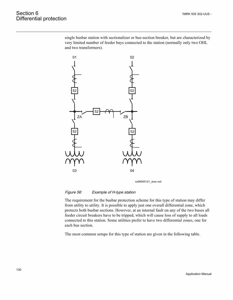
single busbar station with sectionalizer or bus-section breaker, but are characterized byvery limited number of feeder bays connected to the station (normally only two OHLand two transformers).
01 02
0403
ZA ZB
xx06000121_ansi.vsd
52
52 52
5252
ANSI06000121 V1 EN
Figure 56: Example of H-type station
The requirement for the busbar protection scheme for this type of station may differfrom utility to utility. It is possible to apply just one overall differential zone, whichprotects both busbar sections. However, at an internal fault on any of the two buses allfeeder circuit breakers have to be tripped, which will cause loss of supply to all loadsconnected to this station. Some utilities prefer to have two differential zones, one foreach bus section.
The most common setups for this type of station are given in the following table.
Section 6 1MRK 505 302-UUS -Differential protection
130Application Manual

Table 11: Typical solutions for H-type stations
Version of REB670 IED Number of differentialzones/number of feedersper zone
Number of REB670 IEDsrequired for the scheme
3PH; 2-zones, 4-bays BBP (A20) 1/4 1
3PH; 2-zones, 8-bays BBP (A31) 2/3 1
1Ph; 2-zones, 12-bays BBP (B20) NA NA
1Ph; 2-zones, 12-bays BBP (B21) NA NA
1Ph; 2-zones, 24-bays BBP (B31) NA NA
Please note that table 11 is given for the preconfigured versions of REB670 which donot contain any VT inputs.
For station with double zone protection and just one set of CTs in the bus-section bay,it might be required, depending on the client requirements, to provide the specialscheme for disconnection of bus-section CT when the bus-section CB is open. Formore information, refer to figure 45.
6.1.4.6 Double circuit breaker busbar arrangement
The circuit breaker, disconnectors and instrument transformers are duplicated for everyfeeder, as shown in figure 57.
ZB252252 252 252 252
ZA
xx06000018_ansi.vsd
152152152152152
ANSI06000018 V1 EN
Figure 57: Example of double breaker station
This is an extremely flexible solution. In normal service all breakers are closed. Therequirement for busbar protection scheme is that the scheme must have twoindependent differential zones, one for each busbar. If there is an internal fault on oneof the two buses all circuit breakers associated with the faulty busbar have to be
1MRK 505 302-UUS - Section 6Differential protection
131Application Manual

tripped, but supply to any load will not be interrupted. The tripping logic for the circuitbreaker failure protection must be carefully arranged.
The most common setups for this type of busbar arrangement are described in thefollowing table.
Table 12: Typical solutions for double circuit breaker busbar arrangement
Version of REB670 IED Numbers of feeders perstation
Number of REB670 IEDsrequired for the scheme
3PH; 2-zones, 4-bays BBP (A20) 4 2
3PH; 2-zones, 8-bays BBP (A31) 4/8 1/2
1Ph; 2-zones, 12-bays BBP (B20) 6/12 3/6
1Ph; 2-zones, 12-bays BBP (B21) 6/12 3/6
1Ph; 2-zones, 24-bays BBP (B31) 12/24 3/6
Please note that table 12 is given for the preconfigured versions of REB670 which donot contain any VT inputs.
A principle overall drawing of how to use REB670 for this type of station is given infigure 58.
Section 6 1MRK 505 302-UUS -Differential protection
132Application Manual

en06000148_ansi.vsd
Double breaker
REB 670
CTRLZA
CTRLZB
TRIP
CONNZA
CONNZB
Bxxx
I3PB1
BLKTR
TRZONE
TRBAY
BOM
CTRLZA
CTRLZB
TRIP
CONNZA
CONNZB
Bxxx
I3PB1
BLKTR
TRZONE
TRBAY
CT Input
TRM
152 Internal BFP Backup Trip Command
Zone B
Other Equipment
Other Equipment
CT Input
Zone A
A/D
A/D
252 Internal BFP Backup Trip Command
BBP & BFP TRIP 152
BBP & BFP TRIP 252
ORBFP
RemoteFeeder
End Inter-Trip
Feed
er
Parameter ZoneSel must be set to "FixedToZB"
Parameter ZoneSel must be set to "FixedToZA"
152
252
BI1
BI1
152
ANSI06000148 V1 EN
Figure 58: Feeder bay in double bus – double breaker station
6.1.4.7 Breaker-and-a-half busbar arrangements
A fewer number of circuit breakers are needed for the same flexibility as for doublecircuit breaker busbar arrangement, as shown in figure 59.
1MRK 505 302-UUS - Section 6Differential protection
133Application Manual

ZA
ZB
ANSI11000240-1-en.vsd
252 252 252 252 252
152
352
152152152152
352 352 352352
ANSI11000240 V1 EN
Figure 59: Example of breaker-and-a-half station
All breakers are normally closed. The requirement for the busbar protection scheme isthat the scheme must have two independent differential zones, one for each busbar. Incase of an internal fault on one of the two buses, all circuit breakers associated with thefaulty busbar have to be tripped, but the supply to any load will not be interrupted. Thebreaker failure protection tripping logic also needs careful design.
This type of busbar arrangement can be very easily protected. The most commonsetups for this type of station are described in the following table.
Table 13: Typical solutions for breaker-and-a-half stations when CBF for middle breaker is notrequired
Version of REB670 IED Number of diameters inthe station
Number of REB670 IEDsrequired for the scheme
3PH; 2-zones, 4-bays BBP (A20) 2/4 1/2
3PH; 2-zones, 8-bays BBP (A31) 4/8 1/2
1Ph; 2-zones, 12-bays BBP (B20) 6/12 3/6
1Ph; 2-zones, 12-bays BBP (B21) 6/12 3/6
1Ph; 2-zones, 24-bays BBP (B31) 12/24 3/6
Please note that table 13 is given for the preconfigured versions of REB670 which donot contain any VT inputs.
Section 6 1MRK 505 302-UUS -Differential protection
134Application Manual
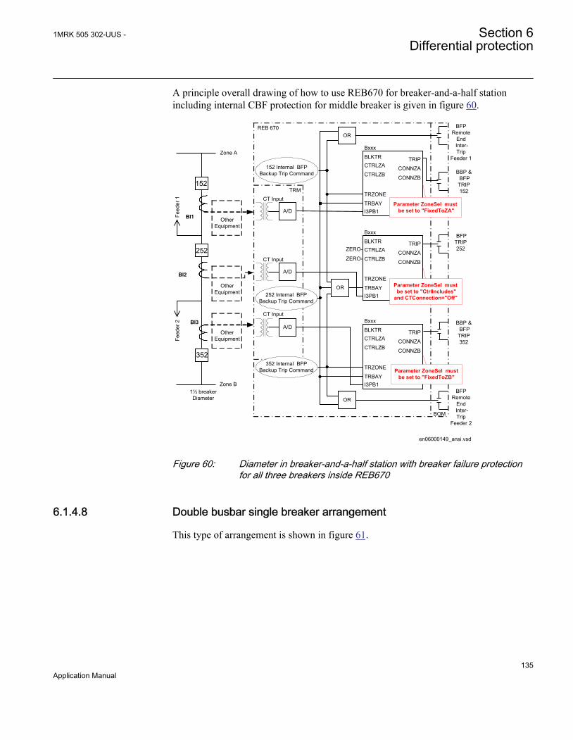
A principle overall drawing of how to use REB670 for breaker-and-a-half stationincluding internal CBF protection for middle breaker is given in figure 60.
en06000149_ansi.vsd
REB 670OR
BFPRemote
End Inter-Trip
Feeder 1CTRLZA
CTRLZB
TRIP
CONNZA
CONNZB
Bxxx
I3PB1
BLKTR
TRZONE
TRBAY
Zone A
BBP & BFP TRIP 152
BFP TRIP 252
BBP & BFP TRIP 352
BFPRemote
End Inter-Trip
Feeder 2
1½ breaker Diameter
CTRLZA
CTRLZB
TRIP
CONNZA
CONNZB
Bxxx
I3PB1
BLKTR
TRZONE
TRBAY
BOM
Parameter ZoneSel must be set to "FixedToZB"
Parameter ZoneSel must be set to "FixedToZA"
CT Input
TRM
152 Internal BFP Backup Trip Command
BI2
Zone B
Other Equipment
Other Equipment
Other Equipment
CT Input
CT Input
CTRLZA
CTRLZB
TRIP
CONNZA
CONNZB
Bxxx
I3PB1
BLKTR
TRZONE
TRBAY
A/D
A/D
A/D
Parameter ZoneSel must be set to "CtrlIncludes"and CTConnection="Off"
ZERO-
ZERO-
252 Internal BFP Backup Trip Command
OR
OR
Feed
er 1
Feed
er 2
352 Internal BFP Backup Trip Command
BI1
BI3
352
152
252
ANSI06000149 V1 EN
Figure 60: Diameter in breaker-and-a-half station with breaker failure protectionfor all three breakers inside REB670
6.1.4.8 Double busbar single breaker arrangement
This type of arrangement is shown in figure 61.
1MRK 505 302-UUS - Section 6Differential protection
135Application Manual
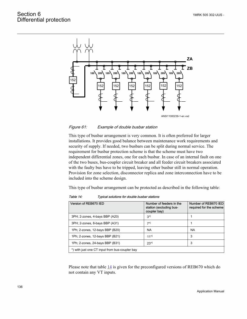
189 289 189 289 189 289 189 289 189 289189 289
ZA
ZB
ANSI11000239-1-en.vsd
152152152152152152
152
ANSI11000239 V1 EN
Figure 61: Example of double busbar station
This type of busbar arrangement is very common. It is often preferred for largerinstallations. It provides good balance between maintenance work requirements andsecurity of supply. If needed, two busbars can be split during normal service. Therequirement for busbar protection scheme is that the scheme must have twoindependent differential zones, one for each busbar. In case of an internal fault on oneof the two buses, bus-coupler circuit breaker and all feeder circuit breakers associatedwith the faulty bus have to be tripped, leaving other busbar still in normal operation.Provision for zone selection, disconnector replica and zone interconnection have to beincluded into the scheme design.
This type of busbar arrangement can be protected as described in the following table:
Table 14: Typical solutions for double busbar stations
Version of REB670 IED Number of feeders in thestation (excluding bus-coupler bay)
Number of REB670 IEDrequired for the scheme
3PH; 2-zones, 4-bays BBP (A20) 3*) 1
3PH; 2-zones, 8-bays BBP (A31) 7*) 1
1Ph; 2-zones, 12-bays BBP (B20) NA NA
1Ph; 2-zones, 12-bays BBP (B21) 11*) 3
1Ph; 2-zones, 24-bays BBP (B31) 23*) 3
*) with just one CT input from bus-coupler bay
Please note that table 14 is given for the preconfigured versions of REB670 which donot contain any VT inputs.
Section 6 1MRK 505 302-UUS -Differential protection
136Application Manual
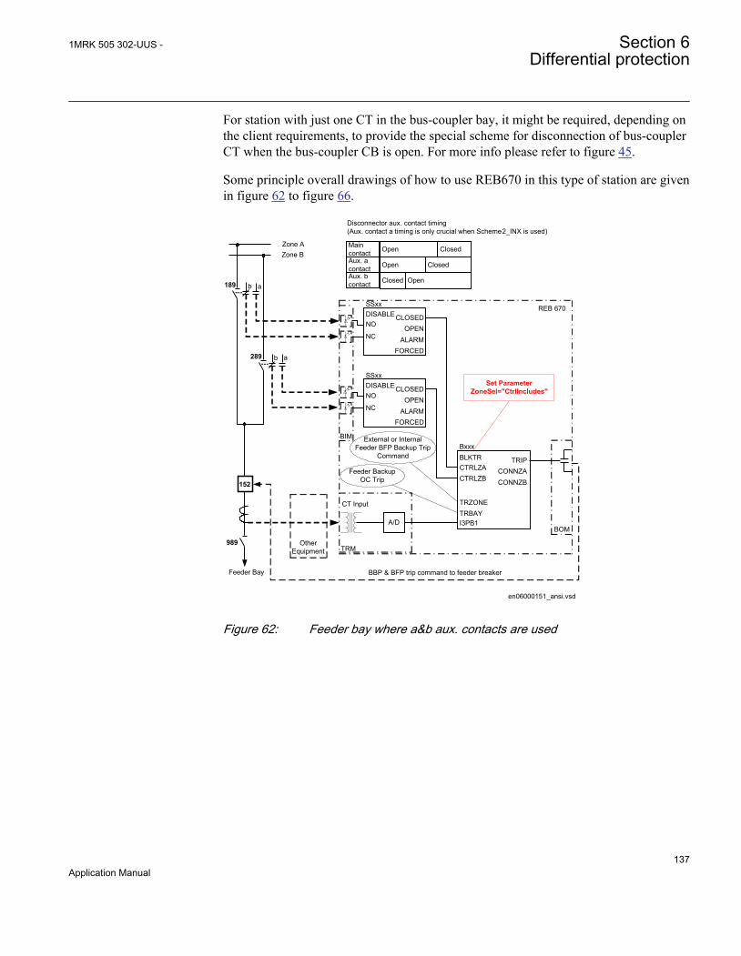
For station with just one CT in the bus-coupler bay, it might be required, depending onthe client requirements, to provide the special scheme for disconnection of bus-couplerCT when the bus-coupler CB is open. For more info please refer to figure 45.
Some principle overall drawings of how to use REB670 in this type of station are givenin figure 62 to figure 66.
en06000151_ansi.vsd
Zone AZone B
Feeder Bay
Other Equipment
REB 670
a
A/D
CT Input
MaincontactAux. acontactAux. bcontact
Open
Open
Closed Open
Closed
Closed
CTRLZACTRLZB
TRIPCONNZACONNZB
Bxxx
I3PB1
BLKTR
TRZONETRBAY
NO
NC
CLOSEDOPEN
ALARMFORCED
SSxxDISABLE
NO
NC
CLOSEDOPEN
ALARMFORCED
SSxxDISABLE
BBP & BFP trip command to feeder breaker
BIM
BOM
Set ParameterZoneSel="CtrlIncludes"
TRM
External or InternalFeeder BFP Backup Trip
Command
Feeder Backup OC Trip
Disconnector aux. contact timing (Aux. contact a timing is only crucial when Scheme2_INX is used)
989
152
b 189
b 289 a
ANSI06000151 V1 EN
Figure 62: Feeder bay where a&b aux. contacts are used
1MRK 505 302-UUS - Section 6Differential protection
137Application Manual

Zone A
Zone B
BI1
REB 670
CT Input
Aux . bcontact
Closed Open
CTRLZA
CTRLZB
TRIP
CONNZA
CONNZB
Bxxx
I3PB1
BLKTR
TRZONE
TRBAY
BBP & BFP trip command to feeder breaker
BIM
BOM
Maincontact
Open Closed
Set ParameterZoneSel=" CtrlExcludes"
Feeder Bay
Other Equipment
A/D
TRM
Feeder Backup OC Trip
Disconnector aux. contact timing
External or InternalFeeder BFP Backup
Trip Command
b 189
989
152
b 289
ANSI06000152_2_en.vsdANSI06000152 V2 EN
Figure 63: Feeder bay where b aux. contacts are used
Section 6 1MRK 505 302-UUS -Differential protection
138Application Manual

en06000153_ansi.vsd
BOM
189
Zone AZone B
Bus-Coupler Bay
REB 670
CTRLZA
CTRLZB
TRIP
CONNZA
CONNZB
Bxxx
I3PB1
BLKTR
TRZONE
TRBAY
BBP & BFP trip command to Bus-Coupler breaker
BI1
BI2
CT Input
A/D
A/D
CTRLZA
CTRLZB
TRIP
CONNZA
CONNZB
Bxxx
I3PB1
BLKTR
TRZONE
TRBAY
Parameter ZoneSel must be set to "FixedToZA"
OR
Other Equipment
Other Equipment
CT Input
TRM
Bus-Coupler Backup OC Trip
289
External or InternalBus-Coupler BFP
Backup Trip Command
Parameter ZoneSel must be set to "FixedToZB"
152
ANSI06000153 V1 EN
Figure 64: Bus coupler bay with two sets of CTs
1MRK 505 302-UUS - Section 6Differential protection
139Application Manual

en06000154_ansi.vsd
Zone AZone B
Bus-Coupler Bay
REB 670
CTRLZACTRLZB
TRIPCONNZACONNZB
Bxxx
I3PB1
BLKTR
TRZONETRBAY
BBP & BFP trip command to Bus-Coupler breaker
BOM
A/D
Parameter ZoneSel must be set to "FixedToZA&-ZB"
tZeroCurrent=150ms
Other Equipment
CT Input TRM
External or InternalBus-Coupler BFP
Backup Trip Command
Bus-Coupler Backup OC Trip
189
289
BI1
NO
NC
CLOSEDOPEN
ALARMFORCED
SSxxDISABLE
ZEROCUR
BIM
CB Closing Signal
tt=1sb
OR152
a
ANSI06000154 V1 EN
Figure 65: Bus coupler bay with one CT and a&b aux. contact from CB
Section 6 1MRK 505 302-UUS -Differential protection
140Application Manual
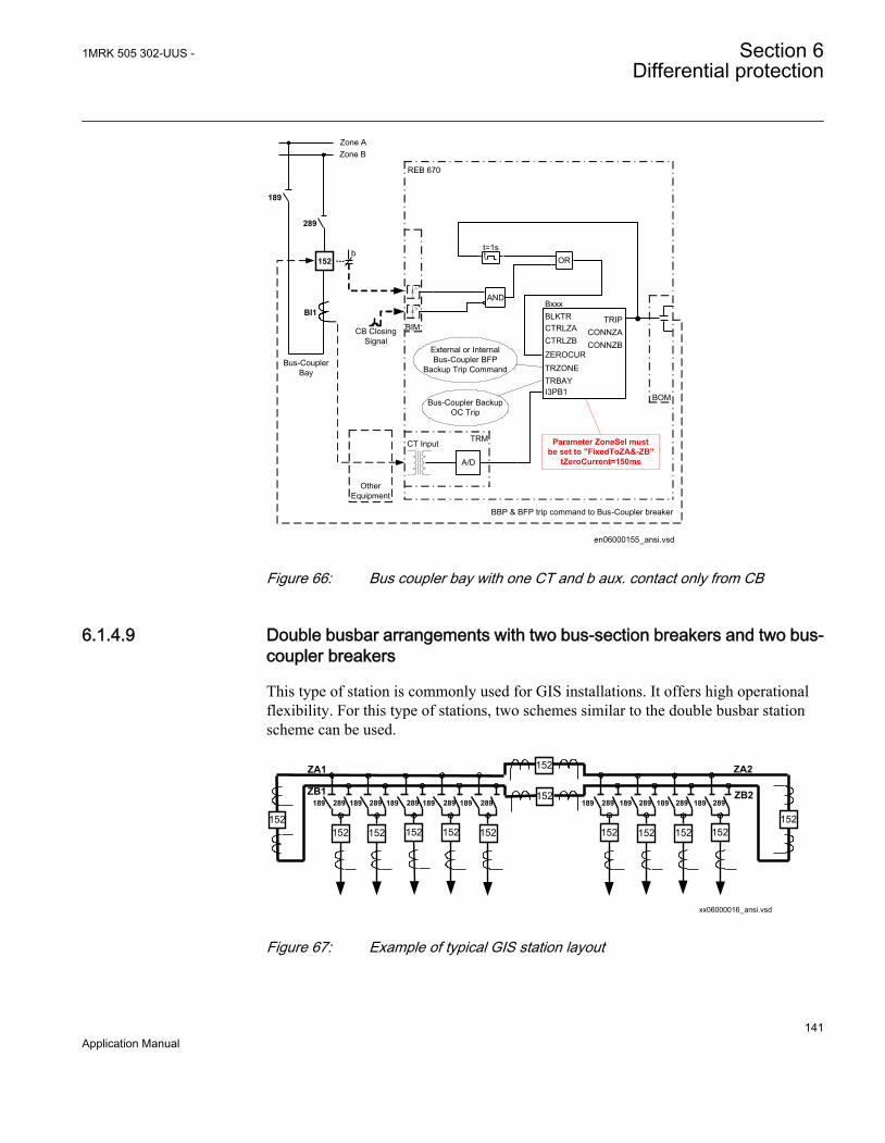
en06000155_ansi.vsd
Zone AZone B
Bus-Coupler Bay
REB 670
CTRLZACTRLZB
TRIPCONNZACONNZB
Bxxx
I3PB1
BLKTR
TRZONETRBAY
BBP & BFP trip command to Bus-Coupler breaker
BOM
A/D
Parameter ZoneSel must be set to "FixedToZA&-ZB"
tZeroCurrent=150ms
Other Equipment
CT Input TRM
External or InternalBus-Coupler BFP
Backup Trip Command
Bus-Coupler Backup OC Trip
189
289
BI1
ZEROCUR
BIMCB Closing Signal
tt=1s
b 152
AND
OR
ANSI06000155 V1 EN
Figure 66: Bus coupler bay with one CT and b aux. contact only from CB
6.1.4.9 Double busbar arrangements with two bus-section breakers and two bus-coupler breakers
This type of station is commonly used for GIS installations. It offers high operationalflexibility. For this type of stations, two schemes similar to the double busbar stationscheme can be used.
189 289 189 289 189 289 189 289 189 289 189 289 189 289 189 289189 289
ZA1
ZB1
ZA2
ZB2
xx06000016_ansi.vsd
152152152152 152 152 152 152 152
152
152
152152
ANSI06000016 V1 EN
Figure 67: Example of typical GIS station layout
1MRK 505 302-UUS - Section 6Differential protection
141Application Manual
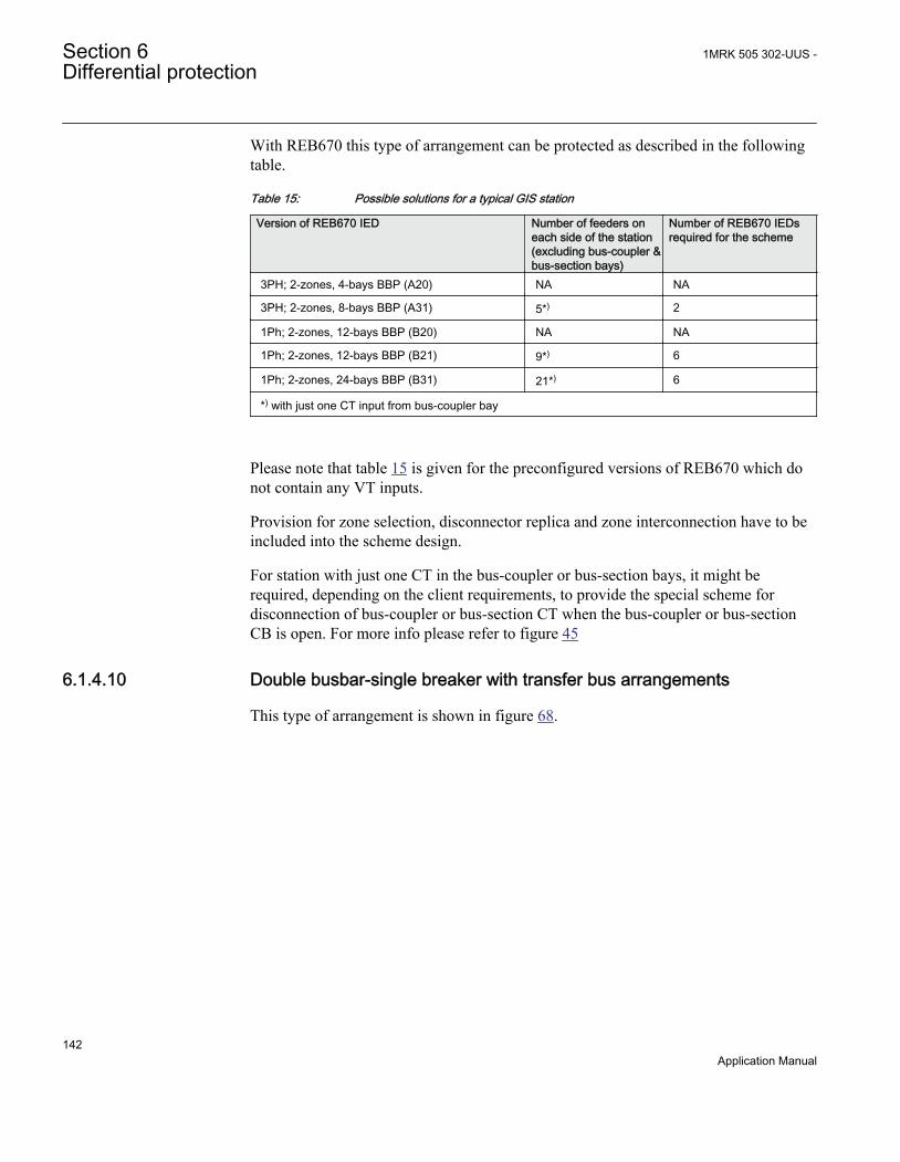
With REB670 this type of arrangement can be protected as described in the followingtable.
Table 15: Possible solutions for a typical GIS station
Version of REB670 IED Number of feeders oneach side of the station(excluding bus-coupler &bus-section bays)
Number of REB670 IEDsrequired for the scheme
3PH; 2-zones, 4-bays BBP (A20) NA NA
3PH; 2-zones, 8-bays BBP (A31) 5*) 2
1Ph; 2-zones, 12-bays BBP (B20) NA NA
1Ph; 2-zones, 12-bays BBP (B21) 9*) 6
1Ph; 2-zones, 24-bays BBP (B31) 21*) 6
*) with just one CT input from bus-coupler bay
Please note that table 15 is given for the preconfigured versions of REB670 which donot contain any VT inputs.
Provision for zone selection, disconnector replica and zone interconnection have to beincluded into the scheme design.
For station with just one CT in the bus-coupler or bus-section bays, it might berequired, depending on the client requirements, to provide the special scheme fordisconnection of bus-coupler or bus-section CT when the bus-coupler or bus-sectionCB is open. For more info please refer to figure 45
6.1.4.10 Double busbar-single breaker with transfer bus arrangements
This type of arrangement is shown in figure 68.
Section 6 1MRK 505 302-UUS -Differential protection
142Application Manual
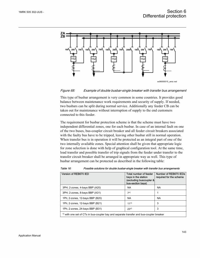
189 289 189 289 189 289 189 289 7892089289 789189
ZAZB
xx06000015_ansi.vsd
152 152 152 152 152
789 789 789
ANSI06000015 V1 EN
Figure 68: Example of double busbar-single breaker with transfer bus arrangement
This type of busbar arrangement is very common in some countries. It provides goodbalance between maintenance work requirements and security of supply. If needed,two busbars can be split during normal service. Additionally any feeder CB can betaken out for maintenance without interruption of supply to the end customersconnected to this feeder.
The requirement for busbar protection scheme is that the scheme must have twoindependent differential zones, one for each busbar. In case of an internal fault on oneof the two buses, bus-coupler circuit breaker and all feeder circuit breakers associatedwith the faulty bus have to be tripped, leaving other busbar still in normal operation.When transfer bus is in operation it will be protected as an integral part of one of thetwo internally available zones. Special attention shall be given that appropriate logicfor zone selection is done with help of graphical configuration tool. At the same time,load transfer and possible transfer of trip signals from the feeder under transfer to thetransfer circuit breaker shall be arranged in appropriate way as well. This type ofbusbar arrangement can be protected as described in the following table:
Table 16: Possible solutions for double busbar-single breaker with transfer bus arrangements
Version of REB670 IED Total number of feederbays in the station(excluding buscoupler &bus-section bays)
Number of REB670 IEDsrequired for the scheme
3PH; 2-zones, 4-bays BBP (A20) NA NA
3PH; 2-zones, 8-bays BBP (A31) 7*) 1
1Ph; 2-zones, 12-bays BBP (B20) NA NA
1Ph; 2-zones, 12-bays BBP (B21) 11*) 3
1Ph; 2-zones, 24-bays BBP (B31) 23*) 3
*) with one set of CTs in bus-coupler bay and separate transfer and bus-coupler breaker
1MRK 505 302-UUS - Section 6Differential protection
143Application Manual

Please note that table 16 is given for the preconfigured versions of REB670 which donot contain any VT inputs.
Note that for station layouts where combined transfer and bus-coupler bay is used, asfor example is shown in figure 68, two internal bay function blocks must be allocatedto such primary bay, reducing number of available feeder bays. In such stationmaximum available number of feeder bays is less for one from the values shown intable 16, on condition that just one main CT is available from Bus-Coupler/Transferbay. For station with just one CT in the bus-coupler bay, it might be required,depending on the client requirements, to provide the logic scheme for disconnection ofbus-coupler CT when the bus-coupler CB is open. For more information, refer tofigure 45.
6.1.4.11 Combined busbar arrangements
There are stations which are practically a combination between two normal types ofstation arrangements, which are already previously described. Some typical exampleswill be shown here:
xx06000123_ansi.vsd
ZA
ZB
152 152152
252 252 252
352 352352
152152
352352
252252
152 252
ANSI06000123 V1 EN
Figure 69: Combination between one-and-half and double breaker station layouts
This type of stations can be encountered very often in practice. Usually the station isarranged in such a way that double breaker bays can be, at a later stage, transformedinto one-and-half breaker setup. For busbar protection this type of station can beprotected in exactly the same way as one-and-half breaker stations described above.
Section 6 1MRK 505 302-UUS -Differential protection
144Application Manual

The same type of IEDs can be used, and same limitations regarding the number ofdiameters apply.
xx06000124_ansi.vsd
ZA
ZB289189289189
152152
252152252152
ANSI06000124 V1 EN
Figure 70: Combination between double breaker and double busbar station layouts
In this type of arrangement the double breaker bay has in the same time the role of thebus-coupler bay for normal double busbar single breaker stations. Therefore, zoneinterconnection, zone selection and disconnector replica facilities have to be providedfor all double busbar bays. Because of the very specific requirements on zoneinterconnection feature, the following should be considered for this type of application:
• current inputs CT1 and CT2 shall be used for the first double breaker bay.• current inputs CT3 and CT4 shall be used for the second double breaker bay.• current inputs CT5 and CT6 shall be used for the third double breaker bay (only
available in 1ph version).
Accordingly the following solutions are possible:
Table 17: Typical solutions for combination between double breaker and double busbar stationlayouts
Version of REB670 IED Number of doublebreaker feeders /Number of doublebusbar feeders in thestation
Number of REB670 IEDsrequired for the scheme
3PH; 2-zones, 4-bays BBP (A20) NA NA
3PH; 2-zones, 8-bays BBP (A31) 2/4 1
1Ph; 2-zones, 12-bays BBP (B20) NA NA
1Ph; 2-zones, 12-bays BBP (B21) 3/6 3
1Ph; 2-zones, 24-bays BBP (B31) 3/18 3
1MRK 505 302-UUS - Section 6Differential protection
145Application Manual

Please note that table 17 is given for the preconfigured versions of REB670 which donot contain any VT inputs.
xx06000125_ansi.vsd
ZA
ZB
152 152152
252 252 252
352 352352
152152
352352
252252
152 152
289189189 289
ANSI06000125 V1 EN
Figure 71: Combination between one-and-half breaker and double busbar stationlayouts
For this type of busbar arrangement the double busbar bay is usually connected to thereactive power compensation equipment (that is, shunt reactor or shunt capacitor). Thediameters in the one-and-half breaker part of the station have at the same time the roleof the bus-coupler bay. Therefore, zone interconnection, zone selection anddisconnector replica facilities have to be provided for all double busbar bays.
6.1.5 Summation principle
6.1.5.1 Introduction
A simplified bus differential protection for phase and ground faults can be obtained byusing a single, one-phase IED with external auxiliary summation current transformers.By using this approach, more cost effective bus differential protection can be obtained.Such a solution makes it feasible to apply bus differential protection even to mediumvoltage substations. The principal differences between full, phase-segregated busdifferential protection scheme and summation type bus differential protection schemeare shown in figure 72.
Section 6 1MRK 505 302-UUS -Differential protection
146Application Manual

Auxiliary Summation CT *)type SLCE 8; 1/1A, 2/1A or 5/1A
+
Three one-phase REB670
Single one-phase REB670
Up to 18 pcsauxiliary CTs
*) One SLCE 8 per main CT
REB670with 1A
CT inputs
REB670 REB670
REB670@
IEC06000126_2_en.vsdIEC06000126 V2 EN
Figure 72: Difference between phase segregated & summation type differentialprotection
In the full, phase-segregated design three, one-phase REB670 IEDs (that is, one perphase) are used. However for the summation type only single, one-phase REB670 IEDplus one auxiliary summation CT per each main CT is required. These auxiliarysummation CTs convert each main CT three-phase currents to a single-phase outputcurrent, which are all measured by one REB670 IED. The differential calculation isthen made on a single-phase basis. By doing so, this more cost effective busdifferential protection can be applied. Due to this characteristic, this summation type ofbus differential protection can be applied for all types of stations arrangements asshown section "Different busbar arrangements", for three, one-phase IEDs.
As an example, the necessary equipment for the summation type, busbar differentialprotection for a single busbar station with up to 24 bays, is shown in figure 73.
1MRK 505 302-UUS - Section 6Differential protection
147Application Manual
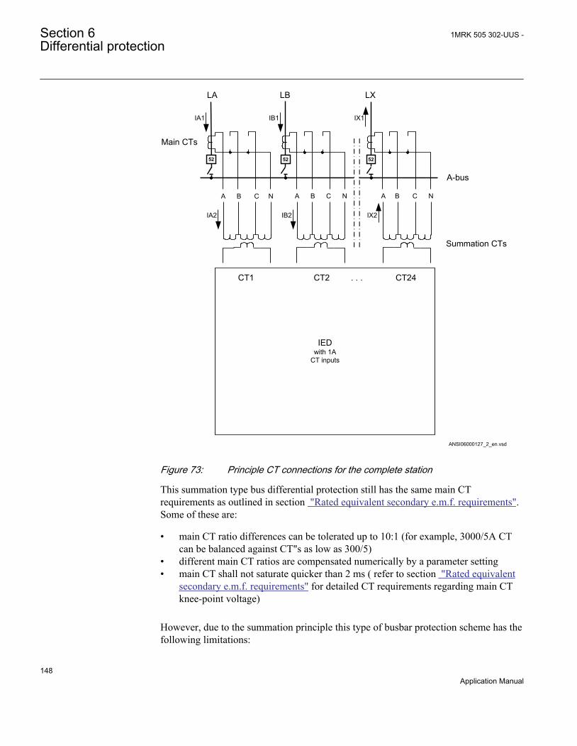
ANSI06000127_2_en.vsd
IEDwith 1A
CT inputs
IB2 IX2IA2
A B C N
IA1 IB1 IX1
LA LB LX
A-bus
Summation CTs
Main CTs
CT1 CT2 . . . CT24
A B C N A B C N
52 52 52
ANSI06000127 V2 EN
Figure 73: Principle CT connections for the complete station
This summation type bus differential protection still has the same main CTrequirements as outlined in section "Rated equivalent secondary e.m.f. requirements".Some of these are:
• main CT ratio differences can be tolerated up to 10:1 (for example, 3000/5A CTcan be balanced against CT"s as low as 300/5)
• different main CT ratios are compensated numerically by a parameter setting• main CT shall not saturate quicker than 2 ms ( refer to section "Rated equivalent
secondary e.m.f. requirements" for detailed CT requirements regarding main CTknee-point voltage)
However, due to the summation principle this type of busbar protection scheme has thefollowing limitations:
Section 6 1MRK 505 302-UUS -Differential protection
148Application Manual
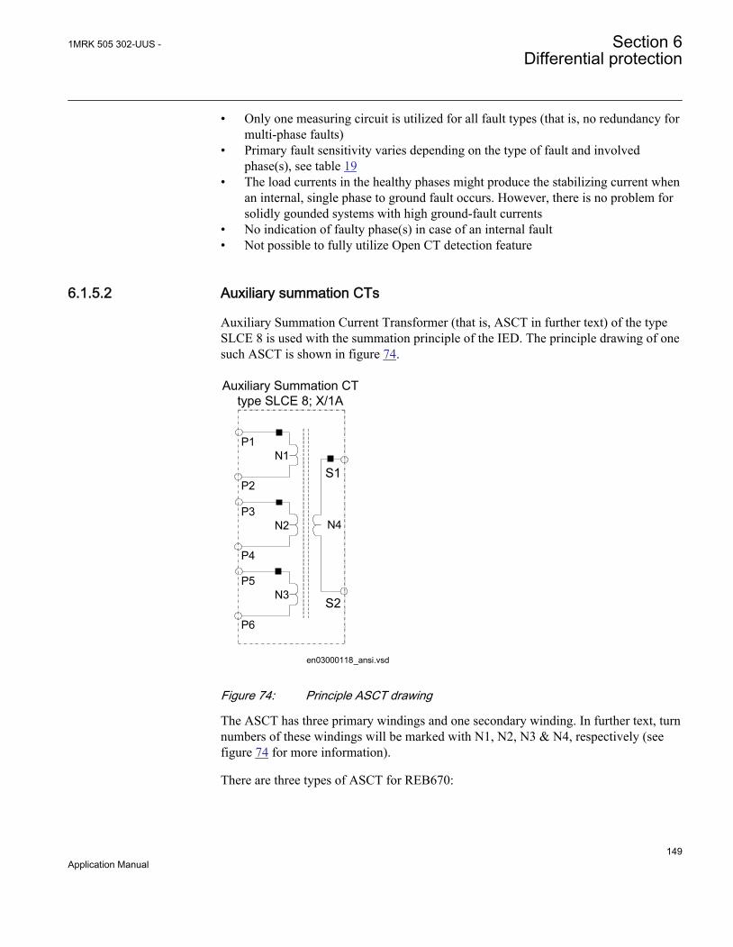
• Only one measuring circuit is utilized for all fault types (that is, no redundancy formulti-phase faults)
• Primary fault sensitivity varies depending on the type of fault and involvedphase(s), see table 19
• The load currents in the healthy phases might produce the stabilizing current whenan internal, single phase to ground fault occurs. However, there is no problem forsolidly gounded systems with high ground-fault currents
• No indication of faulty phase(s) in case of an internal fault• Not possible to fully utilize Open CT detection feature
6.1.5.2 Auxiliary summation CTs
Auxiliary Summation Current Transformer (that is, ASCT in further text) of the typeSLCE 8 is used with the summation principle of the IED. The principle drawing of onesuch ASCT is shown in figure 74.
Auxiliary Summation CT type SLCE 8; X/1A
N4
S1
S2
en03000118_ansi.vsd
P1N1
P2
P3N2
P4
P5N3
P6
ANSI03000118 V1 EN
Figure 74: Principle ASCT drawing
The ASCT has three primary windings and one secondary winding. In further text, turnnumbers of these windings will be marked with N1, N2, N3 & N4, respectively (seefigure 74 for more information).
There are three types of ASCT for REB670:
1MRK 505 302-UUS - Section 6Differential protection
149Application Manual
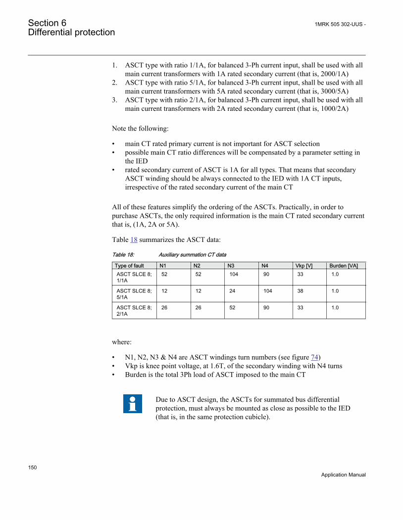
1. ASCT type with ratio 1/1A, for balanced 3-Ph current input, shall be used with allmain current transformers with 1A rated secondary current (that is, 2000/1A)
2. ASCT type with ratio 5/1A, for balanced 3-Ph current input, shall be used with allmain current transformers with 5A rated secondary current (that is, 3000/5A)
3. ASCT type with ratio 2/1A, for balanced 3-Ph current input, shall be used with allmain current transformers with 2A rated secondary current (that is, 1000/2A)
Note the following:
• main CT rated primary current is not important for ASCT selection• possible main CT ratio differences will be compensated by a parameter setting in
the IED• rated secondary current of ASCT is 1A for all types. That means that secondary
ASCT winding should be always connected to the IED with 1A CT inputs,irrespective of the rated secondary current of the main CT
All of these features simplify the ordering of the ASCTs. Practically, in order topurchase ASCTs, the only required information is the main CT rated secondary currentthat is, (1A, 2A or 5A).
Table 18 summarizes the ASCT data:
Table 18: Auxiliary summation CT data
Type of fault N1 N2 N3 N4 Vkp [V] Burden [VA]ASCT SLCE 8;1/1A
52 52 104 90 33 1.0
ASCT SLCE 8;5/1A
12 12 24 104 38 1.0
ASCT SLCE 8;2/1A
26 26 52 90 33 1.0
where:
• N1, N2, N3 & N4 are ASCT windings turn numbers (see figure 74)• Vkp is knee point voltage, at 1.6T, of the secondary winding with N4 turns• Burden is the total 3Ph load of ASCT imposed to the main CT
Due to ASCT design, the ASCTs for summated bus differentialprotection, must always be mounted as close as possible to the IED(that is, in the same protection cubicle).
Section 6 1MRK 505 302-UUS -Differential protection
150Application Manual
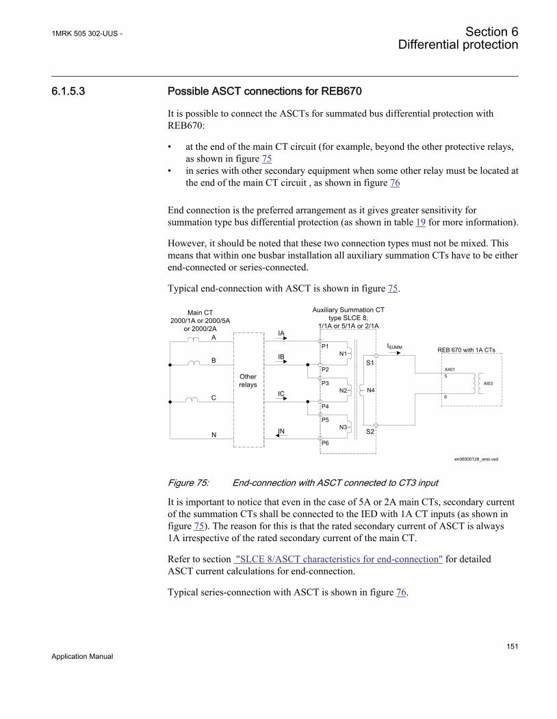
6.1.5.3 Possible ASCT connections for REB670
It is possible to connect the ASCTs for summated bus differential protection withREB670:
• at the end of the main CT circuit (for example, beyond the other protective relays,as shown in figure 75
• in series with other secondary equipment when some other relay must be located atthe end of the main CT circuit , as shown in figure 76
End connection is the preferred arrangement as it gives greater sensitivity forsummation type bus differential protection (as shown in table 19 for more information).
However, it should be noted that these two connection types must not be mixed. Thismeans that within one busbar installation all auxiliary summation CTs have to be eitherend-connected or series-connected.
Typical end-connection with ASCT is shown in figure 75.
en06000128_ansi.vsd
A
B
C
N
IA
IB
IC
IN
Other relays
Auxiliary Summation CT type SLCE 8;
1/1A or 5/1A or 2/1A
N4
S1
S2
Main CT2000/1A or 2000/5A
or 2000/2A
AI03
X4015
6
REB 670 with 1A CTsP1N1
P2
P3N2
P4
P5N3
P6
ISUMM
ANSI06000128 V1 EN
Figure 75: End-connection with ASCT connected to CT3 input
It is important to notice that even in the case of 5A or 2A main CTs, secondary currentof the summation CTs shall be connected to the IED with 1A CT inputs (as shown infigure 75). The reason for this is that the rated secondary current of ASCT is always1A irrespective of the rated secondary current of the main CT.
Refer to section "SLCE 8/ASCT characteristics for end-connection" for detailedASCT current calculations for end-connection.
Typical series-connection with ASCT is shown in figure 76.
1MRK 505 302-UUS - Section 6Differential protection
151Application Manual

Other relays
IA IB IC
en06000129_ansi.vsd
IC
Auxiliary Summation CT type SLCE 8; 1/1 or 5/1A or 2/1A
N4
S1
S2
A103
X4015
6
REB 670 with 1A CTs
CBA N
IA
IN
IN
Main CT2000/1Aor 2000/5A or 2000/2A
ISUMM
Other relays
P1N1
P2P3
N2
P4P5
N3
P6
ANSI06000129 V1 EN
Figure 76: Series-connection with ASCT connected to CT3 input
Refer to section "SLCE 8/ASCT characteristics for series-connection"for detailedASCT current calculation for series-connection.
6.1.5.4 Main CT ratio mismatch correction
As stated before, three types of ASCTs for REB670 are available. The first type shallbe used for main CTs with 1A rated secondary current. The second type shall be usedfor main CTs with 5A rated secondary current. The third type shall be used with 2Amain CTs. However REB670 with 1A CT inputs is always used. Therefore main CTratio shall always be set in such a way that the primary current is entered as for themain CT, but secondary current is always entered as 1A (that is, 3000/5 main CT willbe entered as 3000/1 CT in REB670).
6.1.5.5 Primary pick-up levels for summation type differential protection
The minimal differential operating current level is entered directly in primary amperes.However, as stated previously, in case of the summated differential protection theprimary fault sensitivity varies depending on the type of fault and involved phase(s).The entered value, for the minimal differential operating current level, will exactlycorrespond to the REB670 pickup value in the event of a 3-phase internal fault. For all
Section 6 1MRK 505 302-UUS -Differential protection
152Application Manual

other fault types this value must be multiplied by a coefficient shown in the table 19 inorder to calculate the actual primary pickup value.
Table 19: Pickup coefficients for Summated Differential Protection
Type of fault A-Gnd B-Gnd C-Gnd A-B BC C-A ABCASCT endconnected
0.434 0.578 0.867 1.732 1.732 0.867 1.0
ASCT seriesconnected
1.732 0.867 0.578 1.732 1.732 0.867 1.0
The coefficients in table 19 are only relevant for ideal internal faults(that is, load currents do not exist in the healthy phases).
Example 1:The minimal differential operating current level in the IED is set to 1250A. All ASCTsare series connected. What is the theoretical primary pickup value in case of C-Gnd fault?
Answer 1:According to table 19, pickup coefficient for this type of ASCT connection and thistype of fault is 0.578. Therefore:
IPickup L3 Gnd–( ) 0.578 1250× 722.5A= =
EQUATION1106 V1 EN (Equation 14)
( ) 0.578 1250 722.5PickupI C Gnd A- = × =
EQUATION1784 V1 EN (Equation 14)
This means that if 722.5 primary amperes is injected only in phase C of any of theconnected main CTs, the IED shall display the differential current of 1250A (primary)and should be on the point of the pickup (that is, trip).
In addition to busbar protection differential zones, the IED can incorporate otheradditional functions and features. If and how they can be used together with summationbusbar protection design is shown in table 20:
1MRK 505 302-UUS - Section 6Differential protection
153Application Manual

Table 20: Functions
Functions CommentBusbar Differential Protection Differential Protection, Sensitive differential protection, OCT
algorithm, Check Zone and Differential Supervision featureswill be connected to the summated bay currents. Therefore,they will have different level depending on the type of faultand involved phase(s). For more information, refer totable 19. However, if all these limitations are acceptable it isstill possible to use all these internal busbar protectionfeatures. Note that OCT operating logic will not work properlyin case of opening or shorting the main CT secondary leads(that is, in-between main CT and ASCT). In case of openingor shorting the ASCT secondary leads (that is, in-betweenASCT and the IED) the OCT logic will operate correctly.
Dynamic Zone Selection feature Zone Selection feature in the IED can be used in the exactlysame way as with phase segregated design. All built-infeatures, even including breaker failure protection, protectionback-up trip command routing, EnFP logic can be used in theexactly same way as for phase segregated design.
CCRBRF/CCSRBRF function Breaker Fail Protection function will be connected to thesummated bay current. Therefore it will have different pickuplevel depending on the type of fault and involved phase(s).See table 19 for more info. It will not be possible to haveindividual initiation per phase, but only three-phase initiationcan be effectively used. However, if all these limitations areacceptable it is still possible to use internal CCRBRF/CCSRBRF functions.
OC4PTOC/PHS4PTOCfunction Overcurrent Protection function will be connected to thesummated bay current. Therefore, it will have different pickuplevel depending on the type of fault and involved phase(s).See table 19 for more info. Thus it will be very difficult toinsure proper pickup and time grading with downstreamovercurrent protection relays. Hence it will be quite difficult touse OC4PTOC/PHS4PTOC as backup feeder protection withsummation design.
OC4PTOC/PHS4PTOC function End Fault Protection feature will be connected to thesummated bay current. Therefore it will have different pickuplevel depending on the type of fault and involved phase(s).See table 19 for more info. However, OC4PTOC/PHS4PTOCdo not need any pickup or time coordination with any otherovercurrent protection. Thus if above limitations areacceptable OC4PTOC/PHS4PTOC can be used withsummation design.
DRPRDRE function Disturbance Recording feature will be connected to theindividual summated bay current. Therefore recordedcurrents will not correspond to any actual primary currents.However such DRPRDRE records can still be used toevaluate internal busbar protection, CCRBRF/CCSRBRF andOC4PTOC/PHS4PTOC protections operation.
DRPRDRE function Event List feature in the IED can be used in the exactly thesame way as with phase segregated design.
Table continues on next page
Section 6 1MRK 505 302-UUS -Differential protection
154Application Manual
Functions CommentDRPRDRE function Trip Value Recording feature will be connected to the
individual summated bay current. Therefore recorded tripcurrent values will not correspond to any actual primarycurrents. However such records can still be used to evaluateinternal busbar protection, CCRBRF/CCSRBRF andOC4PTOC/PHS4PTOC protections operation.
Communication All communication features in the IED can be used in theexactly the same way as with phase segregated design
SMBRREC function Autoreclosing function in the IED can be used in the exactlysame way as with phase segregated design.
6.1.5.6 SLCE 8/ASCT characteristics for end-connection
Typical ASCT end-connection is shown in figure 75. For this ASCT connection type,the ampere-turn balance equation has the form according to equation 15:
4 1 2 ( ) 3 ( )SUMMN I N IA N IA IB N IA IB IC× = × + × + + × + +
EQUATION1785-ANSI V1 EN (Equation 15)
The relationships between number of turns for this SLCE 8, ASCT for REB670, isshown in equation 16, equation 17 and equation 18:
N1 N2 N;= =
EQUATION1108 V1 EN (Equation 16)
N3 2 N×=EQUATION1109 V1 EN (Equation 17)
N4 k 3 N× ×=
EQUATION1110 V1 EN (Equation 18)
where:
k is a constant, which depends on the type of ASCT
(that is, k=1, for 1/1A ASCT or k=5 for 5/1A ASCT or k=2 for 2/1A ASCT)
The well-known relationship, between positive, negative and zero sequence currentcomponents and individual phase current quantities is shown in equation 19:
1MRK 505 302-UUS - Section 6Differential protection
155Application Manual

12
22
0
1 1 1
1
1
IA IIB a a IIC a a I
= ×é ù é ù é ùê ú ê ú ê úê ú ê ú ê úê ú ê ú ê úë û ë û ë û
EQUATION1786-ANSI V1 EN (Equation 19)
where:
a is complex constant (that is, a=-0.5+j0.866).
By including equation 16, equation 17, equation 18 and equation 19 into theequation 15 the equation for the end-connected, ASCT secondary current (that is,summated current) can be derived according to equation 20:
ISUMM1k--- I1 e-j30°
× I2 ej30°× 3 3 I0× ×+ +( )×=
EQUATION1112 V1 EN (Equation 20)
From equation 20 it is obvious that the ASCT rated ratio is declared for balanced threephase current system, when only positive sequence current component exist. For anyunbalanced condition (that is, external or internal fault), both negative and zerosequence current components will give their own contribution to the summated current.
6.1.5.7 SLCE 8/ASCT characteristics for series-connection
Typical ASCT series-connection is shown in figure 76. For this ASCT connectiontype, the ampere-turn balance equation has the form according to equation 21:
4 1 2 3( )SUMMN I N IA N IC N IA IB IC× = × - × - + +EQUATION1787-ANSI V1 EN (Equation 21)
The relationships between the number of turns for this SLCE 8 ASCT for REB670, isshown in equation 22, equation 23, equation 24:
N1 N2 N;= =
EQUATION1108 V1 EN (Equation 22)
N3 2 N×=EQUATION1109 V1 EN (Equation 23)
Section 6 1MRK 505 302-UUS -Differential protection
156Application Manual
N4 k 3 N× ×=
EQUATION1110 V1 EN (Equation 24)
where:
k is a constant, which depends on the type of ASCT
(that is, k=1, for 1/1A ASCT or k=5 for 5/1A ASCT or k=2 for 2/1A ASCT).
The well-known relationship, between positive, negative and zero sequence currentcomponents and individual phase current quantities is shown in equation 25:
12
22
0
1 1 1
1
1
IA IIB a a IIC a a I
= ×é ù é ù é ùê ú ê ú ê úê ú ê ú ê úê ú ê ú ê úë û ë û ë û
EQUATION1788-ANSI V1 EN (Equation 25)
where:
a is complex constant (that is, a=-0.5+j0.866).
By including equation 22, equation 23, equation 24 and equation 25 into theequation 21 the equation for the series-connected, ASCT secondary current (that is,summated current) can be derived according to equation 26:
ISUMM1k--- I1 e-j30°
× I2 ej30°× 2 3 I0× ×+ +( )×=
EQUATION1114 V1 EN (Equation 26)
From equation 26 it is obvious that the ASCT rated ratio is declared for balanced threephase current system, when only positive sequence current component exist. For anyunbalanced condition (that is, external or internal fault), both negative and zerosequence current components will give their own contribution to the summated current.
1MRK 505 302-UUS - Section 6Differential protection
157Application Manual

158

Section 7 Current protection
7.1 Four step phase overcurrent protection 3-phaseoutput OC4PTOC (51/67)
7.1.1 IdentificationFunction description IEC 61850
identificationIEC 60617identification
ANSI/IEEE C37.2device number
Four step phase overcurrent protection3-phase output
OC4PTOC
44 alt
3I>
TOC-REVA V1 EN
51/67
7.1.2 ApplicationThe Four step phase overcurrent protection 3-phase output OC4PTOC (51_67) is usedin several applications in the power system. Some applications are:
• Short circuit protection of feeders in distribution and subtransmission systems.Normally these feeders have radial structure.
• Back-up short circuit protection of transmission lines.• Back-up short circuit protection of power transformers.• Short circuit protection of different kinds of equipment connected to the power
system such as; shunt capacitor banks, shunt reactors, motors and others.• Back-up short circuit protection of power generators.
If VT inputs are not available or not connected, setting parameterDirModeSelx (x = step 1, 2, 3 or 4) shall be left to default value Non-directional.
In many applications several steps with different current pick up levels and time delaysare needed. OC4PTOC (51_67) can have up to four different, individual settable, steps.The flexibility of each step of OC4PTOC (51_67) is great. The following options arepossible:
1MRK 505 302-UUS - Section 7Current protection
159Application Manual
Non-directional / Directional function: In most applications the non-directionalfunctionality is used. This is mostly the case when no fault current can be fed from theprotected object itself. In order to achieve both selectivity and fast fault clearance, thedirectional function can be necessary.
Choice of delay time characteristics: There are several types of delay timecharacteristics available such as definite time delay and different types of inverse timedelay characteristics. The selectivity between different overcurrent protections isnormally enabled by co-ordination between the function time delays of the differentprotections. To enable optimal co-ordination between all overcurrent protections, theyshould have the same time delay characteristic. Therefore a wide range of standardizedinverse time characteristics are available: IEC and ANSI. It is also possible to tailormake the inverse time characteristic.
Normally it is required that the phase overcurrent protection shall reset as fast aspossible when the current level gets lower than the operation level. In some cases somesort of delayed reset is required. Therefore different kinds of reset characteristics canbe used.
For some protection applications there can be a need to change the current pick-uplevel for some time. A typical case is when the protection will measure the current to alarge motor. At the start up sequence of a motor the start current can be significantlylarger than the rated current of the motor. Therefore there is a possibility to give asetting of a multiplication factor to the current pick-up level. This multiplication factoris activated from a binary input signal to the function.
Power transformers can have a large inrush current, when being energized. Thisphenomenon is due to saturation of the transformer magnetic core during parts of theperiod. There is a risk that inrush current will reach levels above the pick-up current ofthe phase overcurrent protection. The inrush current has a large 2nd harmonic content.This can be used to avoid unwanted operation of the protection. Therefore, OC4PTOC(51/67) have a possibility of 2nd harmonic restrain if the level of this harmonic currentreaches a value above a set percentage of the fundamental current.
The phase overcurrent protection is often used as protection for two and three phaseshort circuits. In some cases it is not wanted to detect single-phase ground faults by thephase overcurrent protection. This fault type is detected and cleared after operation ofground fault protection. Therefore it is possible to make a choice how many phases, atminimum, that have to have current above the pick-up level, to enable operation. If set1 of 3 it is sufficient to have high current in one phase only. If set 2 of 3 or 3 of 3 single-phase ground faults are not detected.
Section 7 1MRK 505 302-UUS -Current protection
160Application Manual

7.1.3 Setting guidelines
When inverse time overcurrent characteristic is selected, the operatetime of the stage will be the sum of the inverse time delay and the setdefinite time delay. Thus, if only the inverse time delay is required, it isimportant to set the definite time delay for that stage to zero.
The parameters for Four step phase overcurrent protection 3-phase output OC4PTOC(51/67) are set via the local HMI or PCM600.
The following settings can be done for OC4PTOC (51/67).
GlobalBaseSel: Selects the global base value group used by the function to define(IBase), (VBase) and (SBase).
MeasType: Selection of discrete Fourier filtered (DFT) or true RMS filtered (RMS)signals. RMS is used when the harmonic contents are to be considered, for example inapplications with shunt capacitors.
Operation: The protection can be set to Disabled or Enabled
AngleRCA: Protection characteristic angle set in degrees. If the angle of the fault loopcurrent has the angle RCA the direction to fault is forward.
AngleROA: Angle value, given in degrees, to define the angle sector of the directionalfunction, see figure 77.
PUMinOpPhSel: Minimum current for phase selection set in % of IBase. This settingshould be less than the lowest step setting. Default setting is 7%.
NumPhSel: Number of phases, with high current, required for operation. The settingpossibilities are: Not used,1 out of 3, 2 out of 3 and 3 out of 3. Default setting is 1 outof 3.
2ndHarmStab: Operate level of 2nd harmonic current restrain set in % of thefundamental current. The setting range is 5 - 100% in steps of 1%. Default setting is 20%.
1MRK 505 302-UUS - Section 7Current protection
161Application Manual

Vref
Idir
ANSI09000636-1-en.vsd
1
2
2
3
4
ANSI09000636 V1 EN
Figure 77: Directional function characteristic
1. RCA = Relay characteristic angle2. ROA = Relay operating angle3. Reverse4. Forward
7.1.3.1 Settings for each step
x means step 1, 2, 3 and 4.
DirModeSelx: The directional mode of step x. Possible settings are Disabled/Non-directional/Forward/Reverse.
Section 7 1MRK 505 302-UUS -Current protection
162Application Manual

Characteristx: Selection of time characteristic for step x. Definite time delay anddifferent types of inverse time characteristics are available according to table 21.
Table 21: Inverse time characteristics
Curve nameANSI Extremely Inverse
ANSI Very Inverse
ANSI Normal Inverse
ANSI Moderately Inverse
ANSI/IEEE Definite time
ANSI Long Time Extremely Inverse
ANSI Long Time Very Inverse
ANSI Long Time Inverse
IEC Normal Inverse
IEC Very Inverse
IEC Inverse
IEC Extremely Inverse
IEC Short Time Inverse
IEC Long Time Inverse
IEC Definite Time
User Programmable
ASEA RI
RXIDG (logarithmic)
The different characteristics are described in Technical reference manual.
Pickupx: Operate phase current level for step x given in % of IBase.
tx: Definite time delay for step x. Used if definite time characteristic is chosen.
TDx: Time multiplier for inverse time delay for step x.
IMinx: Minimum operate current for step x in % of IBase. Set IMinx below Pickupx forevery step to achieve ANSI reset characteristic according to standard. If IMinx is setabove Pickupx for any step the ANSI reset works as if current is zero when currentdrops below IMinx.
MultPUx: Multiplier for scaling of the current setting value. If a binary input signal(enableMultiplier) is activated the current operation level is increase by this settingconstant. Setting range: 1.0-10.0
1MRK 505 302-UUS - Section 7Current protection
163Application Manual

txMin: Minimum operate time for all inverse time characteristics. At high currents theinverse time characteristic might give a very short operation time. By setting thisparameter the operation time of the step can never be shorter than the setting. Settingrange: 0.000 - 60.000s in steps of 0.001s.
Current
Operatetime
IMinx
txMin
IEC10000058-1-en.vsdIEC10000058 V1 EN
Figure 78: Minimum operate current and operation time for inverse timecharacteristics
In order to fully comply with curves definition setting parameter txMin shall be set tothe value, which is equal to the operating time of the selected inverse curve formeasured current of twenty times the set current pickup value. Note that the operatingtime value is dependent on the selected setting value for time multiplier kx.
ResetTypeCrvx: The reset of the delay timer can be made in different ways. Bychoosing setting the possibilities are according to table 22.
Table 22: Reset possibilities
Curve name Curve index no.Instantaneous 1
IEC Reset (constant time) 2
ANSI Reset (inverse time) 3
Section 7 1MRK 505 302-UUS -Current protection
164Application Manual

The delay characteristics are described in the technical reference manual. There aresome restrictions regarding the choice of reset delay.
For the definite time delay characteristics the possible delay time settings areinstantaneous (1) and IEC (2 = set constant time reset).
For ANSI inverse time characteristics all three types of reset time characteristics areavailable; instantaneous (1), IEC (2 = set constant time reset) and ANSI (3 = currentdependent reset time).
For IEC inverse time characteristics the possible delay time settings are instantaneous(1) and IEC (2 = set constant time reset).
For the customer tailor made inverse time delay characteristics (type 17) all three typesof reset time characteristics are available; instantaneous (1), IEC (2 = set constant timereset) and ANSI (3 = current dependent reset time). If the current dependent type isused settings pr, tr and cr must be given.
HarmRestrainx: Enable block of step x from the harmonic restrain function (2ndharmonic). This function should be used when there is a risk if power transformerinrush currents might cause unwanted trip. Can be set Disabled/Enabled.
tPCrvx, tACrvx, tBCrvx, tCCrvx: Parameters for customer creation of inverse timecharacteristic curve (Curve type = 17). See equation 27 for the time characteristicequation.
[ ]
>
p
At s B MultPUx
iC
in
= + ×
-
æ öç ÷ç ÷ç ÷æ öç ÷ç ÷è øè ø
ANSI-EQUATION1261 V1 EN (Equation 27)
For more information, refer to the technical reference manual.
tPRCrvx, tTRCrvx, tCRCrvx: Parameters for customer creation of inverse reset timecharacteristic curve (Reset Curve type = 3). Further description can be found in thetechnical reference manual.
7.2 Four step single phase overcurrent protectionPH4SPTOC (51)
1MRK 505 302-UUS - Section 7Current protection
165Application Manual

7.2.1 IdentificationFunction description IEC 61850
identificationIEC 60617identification
ANSI/IEEE C37.2device number
Four step single phase overcurrentprotection
PH4SPTOC
44 alt
I>
OC V1 EN
51
7.2.2 ApplicationThe Four step single phase overcurrent protection(PH4SPTOC, 51) function is used inseveral applications in the power system. Some applications are:
• Short circuit protection of feeders in distribution and subtransmission systems.Normally these feeders have radial structure.
• Back-up short circuit protection of transmission lines.• Back-up short circuit protection of power transformers• Short circuit protection of different kinds of equipment connected to the power
system such as; shunt capacitor banks, shunt reactors, motors and others.• Back-up short circuit protection of power generators.
The single phase overcurrent protection is used in IEDs having only input from onephase, for example busbar protection for large busbars (with many bays).
In many applications several steps with different current pick up levels and time delaysare needed. PH4SPTOC(51) can have up to four different, individual settable, steps.The flexibility of each step of PH4SPTOC(51) function is great. The followingoptions are possible:
Choice of delay time characteristics: There are several types of time delaycharacteristics available such as definite time delay and different types of inverse timedelay characteristics. The selectivity between different overcurrent protections isnormally enabled by co-ordination between the function time delays of the differentprotections. To enable optimal co-ordination all overcurrent IEDs, to be co-ordinatedagainst each other, should have the same time delay characteristic. Therefore a widerange of standardised inverse time characteristics are available: IEC and ANSI. It isalso possible to programme a user defined inverse time characteristic.
Normally it is required that the phase overcurrent function shall reset as fast as possiblewhen the current level gets lower than the operation level. In some cases some sort oftime delayed reset is required. Therefore three different kinds of reset timecharacteristics can be used.
Section 7 1MRK 505 302-UUS -Current protection
166Application Manual
For some protection applications there can be a need to change the current pick-uplevel for some time. A typical case is when the protection will measure the current to alarge motor. At the start up sequence of a motor the start current can be significantlylarger then the rated current of the motor. Therefore there is a possibility to give asetting of a multiplication factor to the current pick-up level. This multiplication factoris activated from a binary input signal to the function.
Power transformers can have a large inrush current, when being energized. Thisphenomenon is due to saturation of the transformer magnetic core during parts of theperiod. There is a risk that inrush current will reach levels above the pick-up current ofthe phase overcurrent protection. The inrush current has a large second harmoniccontent. This can be used to avoid unwanted operation of the protection. Therefore theFour step phase overcurrent protection (OC4PTOC, 51/67) function have a possibilityof second harmonic restrain if the level of this harmonic current reaches a value abovea set percentage of the fundamental current.
7.2.3 Setting guidelinesThe parameters for the four step phase overcurrent protection function (OC) are set viathe local HMI or Protection and Control IED Manager (PCM 600).
The following settings can be done for the four step phase overcurrent protection.
Operation: Off/On
IBase: Base current in primary A. This current is used as reference for current setting.It can be suitable to set this parameter to the rated primary current of the protected object.
2ndHarmStab: Operate level of 2nd harmonic current restrain set in % of thefundamental current. The setting range is 5-100% of IBase in steps of 1%. Defaultsetting is 20%.
HarmRestrainx: Disabled/Enabled, enables blocking from harmonic restrain.
7.2.3.1 Settings for each step (x = 1-4)
Characteristx: Selection of time delay characteristic for step x. Definite time delay anddifferent types of inverse time delay characteristics are available according to table 23.
Table 23: Inverse time delay characteristics
Curve nameANSI Extremely Inverse
ANSI Very Inverse
ANSI Normal Inverse
Table continues on next page
1MRK 505 302-UUS - Section 7Current protection
167Application Manual
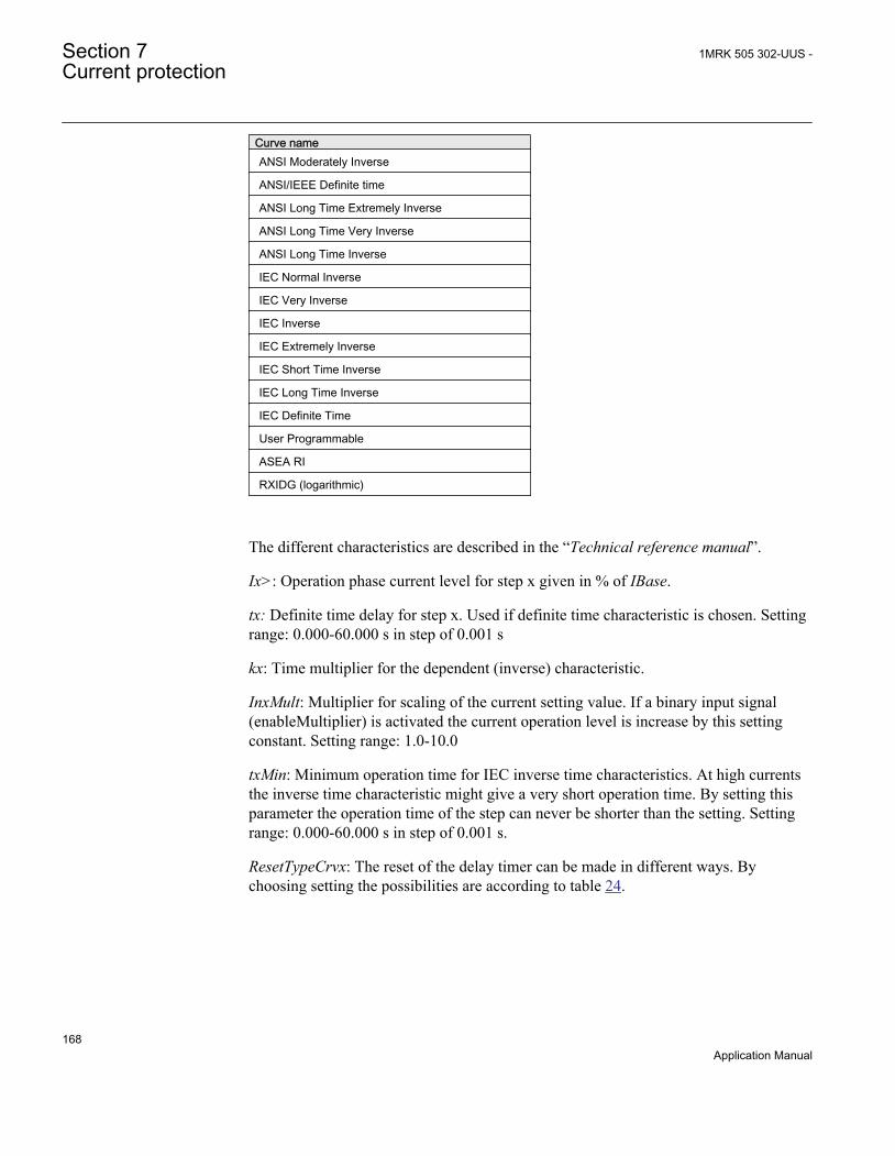
Curve nameANSI Moderately Inverse
ANSI/IEEE Definite time
ANSI Long Time Extremely Inverse
ANSI Long Time Very Inverse
ANSI Long Time Inverse
IEC Normal Inverse
IEC Very Inverse
IEC Inverse
IEC Extremely Inverse
IEC Short Time Inverse
IEC Long Time Inverse
IEC Definite Time
User Programmable
ASEA RI
RXIDG (logarithmic)
The different characteristics are described in the “Technical reference manual”.
Ix>: Operation phase current level for step x given in % of IBase.
tx: Definite time delay for step x. Used if definite time characteristic is chosen. Settingrange: 0.000-60.000 s in step of 0.001 s
kx: Time multiplier for the dependent (inverse) characteristic.
InxMult: Multiplier for scaling of the current setting value. If a binary input signal(enableMultiplier) is activated the current operation level is increase by this settingconstant. Setting range: 1.0-10.0
txMin: Minimum operation time for IEC inverse time characteristics. At high currentsthe inverse time characteristic might give a very short operation time. By setting thisparameter the operation time of the step can never be shorter than the setting. Settingrange: 0.000-60.000 s in step of 0.001 s.
ResetTypeCrvx: The reset of the delay timer can be made in different ways. Bychoosing setting the possibilities are according to table 24.
Section 7 1MRK 505 302-UUS -Current protection
168Application Manual

Table 24: Reset possibilities
Curve name Curve index no.Instantaneous 1
IEC Reset (constant time) 2
ANSI Reset (inverse time) 3
The delay characteristics are described in the “Technical reference manual”. There aresome restrictions regarding the choice of reset delay.
For the independent time delay characteristics the possible delay time settings areinstantaneous (1) and IEC (2 = set constant time reset).
For ANSI inverse time delay characteristics all three types of reset time characteristicsare available; instantaneous (1), IEC (2 = set constant time reset) and ANSI (3 =current dependent reset time).
For IEC inverse time delay characteristics the possible delay time settings areinstantaneous (1) and IEC (2 = set constant time reset).
For the customer tailor made inverse time delay characteristics (type 17) all three typesof reset time characteristics are available; instantaneous (1), IEC (2 = set constant timereset) and ANSI (3 = current dependent reset time). If the current dependent type isused then settings pr, tr and cr must be given.
HarmRestrainx: Enable block of step x from the harmonic restrain function (2ndharmonic). This function should be used when there is a risk if power transformerinrush currents might cause unwanted trip. Can be set Off/On.
tPCrvx, tACrvx, tBCrvx, tCCrvx: Parameters for customer creation of inverse timecharacteristic curve (Curve type = 17). See equation 28 for the time characteristicequation.
[ ]
>
p
At s B IxMult
iC
in
= + ×
-
æ öç ÷ç ÷ç ÷æ öç ÷ç ÷è øè ø
EQUATION1261 V2 EN (Equation 28)
For more information, please refer to the “Technical reference manual”.
tPRCrvx, tTRCrvx, tCRCrvx: Parameters for customer creation of inverse reset timecharacteristic curve (Reset Curve type = 3). Further description can be found in the“Technical reference manual”.
1MRK 505 302-UUS - Section 7Current protection
169Application Manual

7.2.3.2 Second harmonic restrain
If a power transformer is energized there is a risk that the transformer core will saturateduring part of the period, resulting in an inrush transformer current. This will give adeclining residual current in the network, as the inrush current is deviating between thephases. There is a risk that the phase overcurrent function will give an unwanted trip.The inrush current has a relatively large ratio of 2nd harmonic component. Thiscomponent can be used to create a restrain signal to prevent this unwanted function.
The settings for the 2nd harmonic restrain are described below.
2ndHarmStab: The rate of second harmonic current content for activation of the 2nd
harmonic restrain signal, to block chosen steps. The setting is given in % of thefundamental frequency residual current. The setting range is 5-100% in step of 1%.The default setting is 20%.
HarmRestrainx: This parameter can be set Off/On, disable or enable the 2nd harmonicrestrain.
The four-step phase overcurrent protection can be used in different ways, depending onthe application where the protection is used. A general description is given below.
The pick up current setting inverse time protection or the lowest current step constantinverse time protection must be given a current setting so that the highest possible loadcurrent does not cause protection operation. Here consideration also has to be taken tothe protection reset current, so that a short peak of overcurrent does not cause operationof the protection even when the overcurrent has ceased. This phenomenon is describedin figure 79.
Section 7 1MRK 505 302-UUS -Current protection
170Application Manual

Operate current
Current I
The IED does not reset
Line phase current
Time t
Reset current
IEC05000203-en-2.vsdIEC05000203 V3 EN
Figure 79: Pick up and reset current for an overcurrent protection
The lowest setting value can be written according to equation 29.
ImaxIpu 1.2k
³ ×
EQUATION1262 V2 EN (Equation 29)
where:
1.2 is a safety factor,
k is the resetting ratio of the protection, and
Imax is the maximum load current.
The maximum load current on the line has to be estimated. From operation statisticsthe load current up to the present situation can be found. The current setting must bevalid also for some years ahead. It is, in most cases, realistic that the setting values areupdated not more often than once every five years. In many cases this time interval isstill longer. Investigate the maximum load current that different equipment on the linecan withstand. Study components such as line conductors, current transformers, circuit
1MRK 505 302-UUS - Section 7Current protection
171Application Manual

breakers, and disconnectors. The manufacturer of the equipment normally gives themaximum thermal load current of the equipment.
There is also a demand that all faults, within the zone that the protection shall cover,must be detected by the phase overcurrent protection. The minimum fault currentIscmin, to be detected by the protection, must be calculated. Taking this value as a base,the highest pick up current setting can be written according to equation 30.
Ipu 0.7 Iscmin£ ×EQUATION1263 V2 EN (Equation 30)
where:
0.7 is a safety factor and
Iscmin is the smallest fault current to be detected by the overcurrent protection.
As a summary the pick up current shall be chosen within the interval stated inequation 31.
Imax1.2 Ipu 0.7 Iscmink
× £ £ ×
EQUATION1264 V2 EN (Equation 31)
The high current function of the overcurrent protection, which only has a short delayof the operation, must be given a current setting so that the protection is selective toother protection in the power system. It is desirable to have a rapid tripping of faultswithin as large portion as possible of the part of the power system to be protected bythe protection (primary protected zone). A fault current calculation gives the largestcurrent of faults, Iscmax, at the most remote part of the primary protected zone.Considerations have to be made to the risk of transient overreach, due to a possible DCcomponent of the short circuit current. The lowest current setting of the most rapidstage, of the phase overcurrent protection, can be written according to
max1.2 t schighI k I³ × ×
EQUATION1265 V1 EN (Equation 32)
where:
1.2 is a safety factor,
kt is a factor that takes care of the transient overreach due to the DC component of the fault currentand can be considered to be less than 1.1
Iscmax is the largest fault current at a fault at the most remote point of the primary protection zone.
Section 7 1MRK 505 302-UUS -Current protection
172Application Manual

The operate times of the phase overcurrent protection has to be chosen so that the faulttime is so short so that equipment will not be destroyed due to thermal overload, at thesame time as selectivity is assured. For overcurrent protection, in a radial fed network,the time setting can be chosen in a graphical way. This is mostly used in the case ofinverse time overcurrent protection. In the figure below is shown how the time-versus-current curves are plotted in a diagram. The time setting is chosen to get the shortestfault time with maintained selectivity. Selectivity is assured if the time differencebetween the curves is larger than a critical time difference.
en05000204.wmfIEC05000204 V1 EN
Figure 80: Fault time with maintained selectivity
The operation time can be set individually for each overcurrent protection. To assureselectivity between different protective protections, in the radial network, there have tobe a minimum time difference Dt between the time delays of two protections. Theminimum time difference can be determined for different cases. To determine theshortest possible time difference between we must have knowledge about operationtime of protections, breaker opening time and protection resetting time. These timedelays can vary significantly between different pieces of equipment. The followingtime delays can be estimated:
1MRK 505 302-UUS - Section 7Current protection
173Application Manual
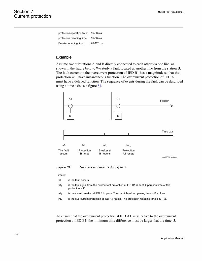
protection operation time: 15-60 ms
protection resetting time: 15-60 ms
Breaker opening time: 20-120 ms
ExampleAssume two substations A and B directly connected to each other via one line, asshown in the figure below. We study a fault located at another line from the station B.The fault current to the overcurrent protection of IED B1 has a magnitude so that theprotection will have instantaneous function. The overcurrent protection of IED A1must have a delayed function. The sequence of events during the fault can be describedusing a time axis, see figure 81.
I> I>
A1 B1 Feeder
Time axis
t=0 t=t1 t=t2 t=t3The faultoccurs
ProtectionB1 trips
Breaker atB1 opens
ProtectionA1 resets
en05000205.vsd
IEC05000205 V1 EN
Figure 81: Sequence of events during fault
where:
t=0 is the fault occurs,
t=t1 is the trip signal from the overcurrent protection at IED B1 is sent. Operation time of thisprotection is t1,
t=t2 is the circuit breaker at IED B1 opens. The circuit breaker opening time is t2 - t1 and
t=t3 is the overcurrent protection at IED A1 resets. The protection resetting time is t3 - t2.
To ensure that the overcurrent protection at IED A1, is selective to the overcurrentprotection at IED B1, the minimum time difference must be larger that the time t3.
Section 7 1MRK 505 302-UUS -Current protection
174Application Manual

There are uncertainties in the values of protection operation time, breaker opening timeand protection resetting time. Therefor a safety margin has to be included. With normalvalues the needed time difference can be calculated according to equation 33.
40 100 40 40 220t ms ms ms ms msD ³ + + + =EQUATION1266 V1 EN (Equation 33)
where it is considered that:
the operation time of overcurrent protection B1 is 40 ms
the breaker open time is 100 ms
the resetting time of protection A1 is 40 ms and
the additional margin is 40 ms
7.3 Four step residual overcurrent protection, (Zerosequence or negative sequence directionality)EF4PTOC (51N/67N)
7.3.1 IdentificationFunction description IEC 61850
identificationIEC 60617identification
ANSI/IEEE C37.2device number
Four step residual overcurrentprotection
EF4PTOC
44 alt
IN
TEF-REVA V1 EN
51N/67N
7.3.2 Setting guidelines
When inverse time overcurrent characteristic is selected, the operatetime of the stage will be the sum of the inverse time delay and the setdefinite time delay. Thus, if only the inverse time delay is required, it isof utmost importance to set the definite time delay for that stage to zero.
The parameters for the four step residual overcurrent protection, zero or negativesequence direction EF4PTOC (51N/67N) are set via the local HMI or PCM600.
The following settings can be done for the four step residual overcurrent protection.
1MRK 505 302-UUS - Section 7Current protection
175Application Manual
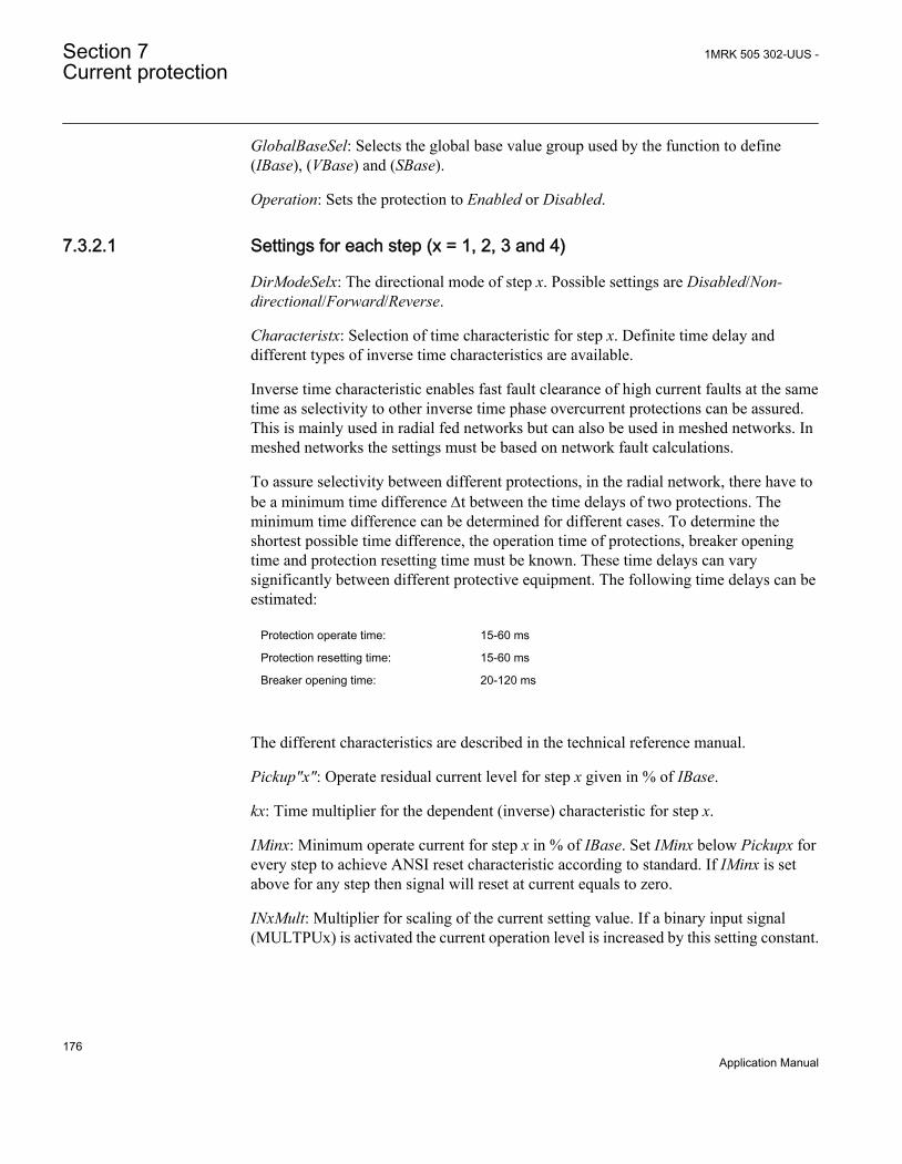
GlobalBaseSel: Selects the global base value group used by the function to define(IBase), (VBase) and (SBase).
Operation: Sets the protection to Enabled or Disabled.
7.3.2.1 Settings for each step (x = 1, 2, 3 and 4)
DirModeSelx: The directional mode of step x. Possible settings are Disabled/Non-directional/Forward/Reverse.
Characteristx: Selection of time characteristic for step x. Definite time delay anddifferent types of inverse time characteristics are available.
Inverse time characteristic enables fast fault clearance of high current faults at the sametime as selectivity to other inverse time phase overcurrent protections can be assured.This is mainly used in radial fed networks but can also be used in meshed networks. Inmeshed networks the settings must be based on network fault calculations.
To assure selectivity between different protections, in the radial network, there have tobe a minimum time difference Dt between the time delays of two protections. Theminimum time difference can be determined for different cases. To determine theshortest possible time difference, the operation time of protections, breaker openingtime and protection resetting time must be known. These time delays can varysignificantly between different protective equipment. The following time delays can beestimated:
Protection operate time: 15-60 ms
Protection resetting time: 15-60 ms
Breaker opening time: 20-120 ms
The different characteristics are described in the technical reference manual.
Pickup"x": Operate residual current level for step x given in % of IBase.
kx: Time multiplier for the dependent (inverse) characteristic for step x.
IMinx: Minimum operate current for step x in % of IBase. Set IMinx below Pickupx forevery step to achieve ANSI reset characteristic according to standard. If IMinx is setabove for any step then signal will reset at current equals to zero.
INxMult: Multiplier for scaling of the current setting value. If a binary input signal(MULTPUx) is activated the current operation level is increased by this setting constant.
Section 7 1MRK 505 302-UUS -Current protection
176Application Manual

txMin: Minimum operating time for inverse time characteristics. At high currents theinverse time characteristic might give a very short operation time. By setting thisparameter the operation time of the step can never be shorter than the setting.
Current
Operatetime
IMinx
txMin
IEC10000058-1-en.vsdIEC10000058 V1 EN
Figure 82: Minimum operate current and operate time for inverse timecharacteristics
In order to fully comply with curves definition the setting parameter txMin shall be setto the value which is equal to the operate time of the selected IEC inverse curve formeasured current of twenty times the set current pickup value. Note that the operatetime value is dependent on the selected setting value for time multiplier kx.
ResetTypeCrvx: The reset of the delay timer can be made in different ways. Thepossibilities are described in the technical reference manual.
tPCrvx, tACrvx, tBCrvx, tCCrvx: Parameters for user programmable of inverse timecharacteristic curve. The time characteristic equation is according to equation 34:
1MRK 505 302-UUS - Section 7Current protection
177Application Manual
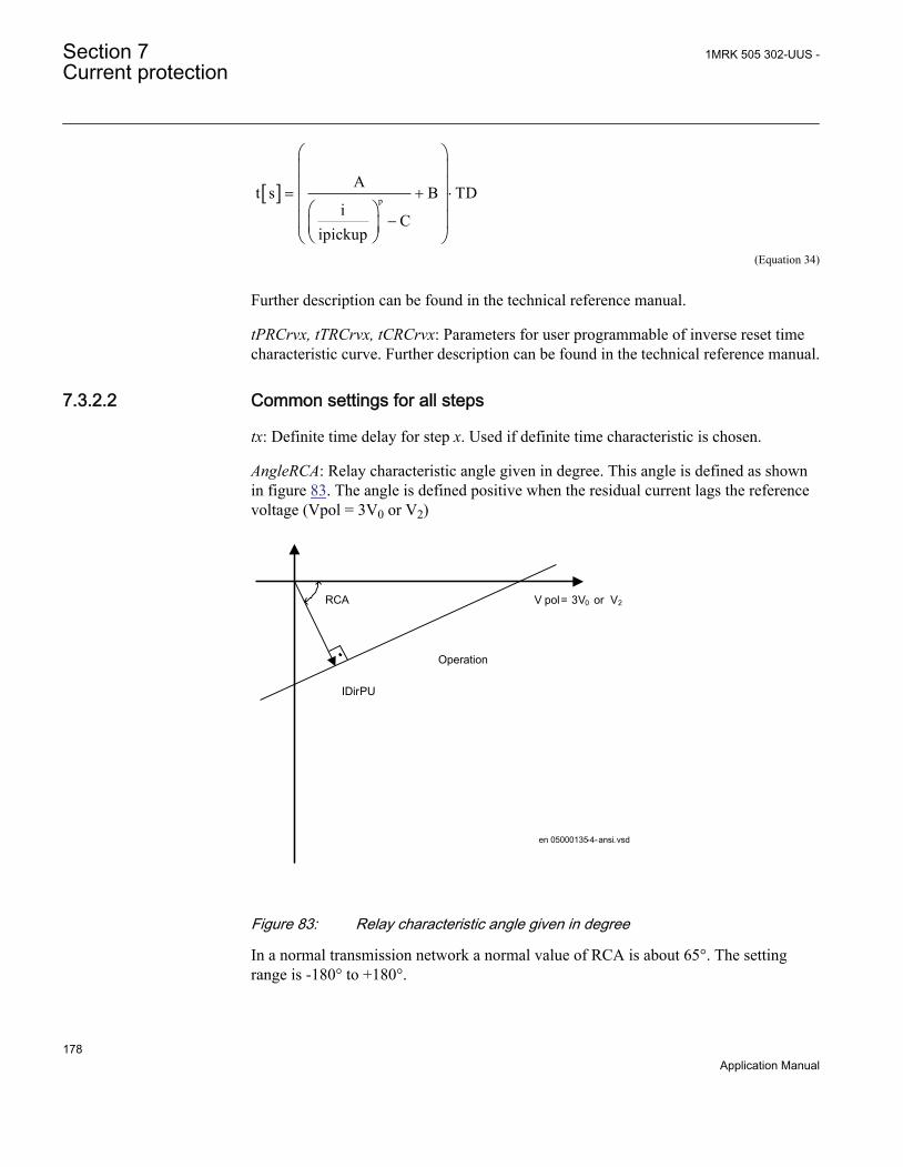
[ ] p
At s B TD
iC
ipickup
= + ×
-
æ öç ÷ç ÷ç ÷æ öç ÷ç ÷è øè ø
EQUATION1722 V1 EN (Equation 34)
Further description can be found in the technical reference manual.
tPRCrvx, tTRCrvx, tCRCrvx: Parameters for user programmable of inverse reset timecharacteristic curve. Further description can be found in the technical reference manual.
7.3.2.2 Common settings for all steps
tx: Definite time delay for step x. Used if definite time characteristic is chosen.
AngleRCA: Relay characteristic angle given in degree. This angle is defined as shownin figure 83. The angle is defined positive when the residual current lags the referencevoltage (Vpol = 3V0 or V2)
V pol = 3V0 or V2RCA
Operation
IDirPU
en 05000135-4-ansi.vsd
ANSI05000135 V3 EN
Figure 83: Relay characteristic angle given in degree
In a normal transmission network a normal value of RCA is about 65°. The settingrange is -180° to +180°.
Section 7 1MRK 505 302-UUS -Current protection
178Application Manual

polMethod: Defines if the directional polarization is from
• Voltage (3V0 or V2)• Current (3I0 · ZNpol or 3I2 ·ZNpol where ZNpol is RNpol + jXNpol), or• both currents and voltage, Dual (dual polarizing, (3V0 + 3I0 · ZNpol) or (V2 + I2 ·
ZNpol)).
Normally voltage polarizing from the internally calculated residual sum or an externalopen delta is used.
Current polarizing is useful when the local source is strong and a high sensitivity isrequired. In such cases the polarizing voltage (3V0) can be below 1% and it is thennecessary to use current polarizing or dual polarizing. Multiply the required set current(primary) with the minimum impedance (ZNpol) and check that the percentage of thephase-to-ground voltage is definitely higher than 1% (minimum 3V0>VPolMin setting)as a verification.
RNPol, XNPol: The zero-sequence source is set in primary ohms as base for the currentpolarizing. The polarizing voltage is then achieved as 3I0 · ZNpol. The ZNpol can bedefined as (ZS1-ZS0)/3, that is the ground return impedance of the source behind theprotection. The maximum ground-fault current at the local source can be used tocalculate the value of ZN as V/(√3 · 3I0) Typically, the minimum ZNPol (3 · zerosequence source) is set. Setting is in primary ohms.
When the dual polarizing method is used it is important that the settingPickupxor theproduct 3I0 · ZNpol is not greater than 3V0. If so, there is a risk for incorrect operationfor faults in the reverse direction.
IPolMin: is the minimum ground-fault current accepted for directional evaluation. Forsmaller currents than this value the operation will be blocked. Typical setting is 5-10%of IBase.
VPolMin: Minimum polarization (reference) polarizing voltage for the directionalfunction, given in % of VBase/√3.
IDirPU: Operate residual current release level in % of IBase for directional comparisonscheme. The setting is given in % of IBase and must be set below the lowest INx>setting, set for the directional measurement. The output signals, PUFW and PUREVcan be used in a teleprotection scheme. The appropriate signal should be configured tothe communication scheme block.
7.3.2.3 2nd harmonic restrain
If a power transformer is energized there is a risk that the current transformer core willsaturate during part of the period, resulting in a transformer inrush current. This will
1MRK 505 302-UUS - Section 7Current protection
179Application Manual

give a declining residual current in the network, as the inrush current is deviatingbetween the phases. There is a risk that the residual overcurrent function will give anunwanted trip. The inrush current has a relatively large ratio of 2nd harmoniccomponent. This component can be used to create a restrain signal to prevent thisunwanted function.
At current transformer saturation a false residual current can be measured by theprotection. Also here the 2nd harmonic restrain can prevent unwanted operation.
2ndHarmStab: The rate of 2nd harmonic current content for activation of the 2ndharmonic restrain signal. The setting is given in % of the fundamental frequencyresidual current.
HarmRestrainx: Enable block of step x from the harmonic restrain function.
7.3.2.4 Parallel transformer inrush current logic
In case of parallel transformers there is a risk of sympathetic inrush current. If one ofthe transformers is in operation, and the parallel transformer is switched in, theasymmetric inrush current of the switched in transformer will cause partial saturationof the transformer already in service. This is called transferred saturation. The 2nd
harmonic of the inrush currents of the two transformers will be in phase opposition.The summation of the two currents will thus give a small 2nd harmonic current. Theresidual fundamental current will however be significant. The inrush current of thetransformer in service before the parallel transformer energizing, will be a littledelayed compared to the first transformer. Therefore we will have high 2nd harmoniccurrent initially. After a short period this current will however be small and the normal2nd harmonic blocking will reset.
en05000136_ansi.vsd
Power System
51N51N
ANSI05000136 V1 EN
Figure 84: Application for parallel transformer inrush current logic
If the BlkParTransf function is activated the 2nd harmonic restrain signal will latch aslong as the residual current measured by the relay is larger than a selected step currentlevel. Assume that step 4 is chosen to be the most sensitive step of the four step
Section 7 1MRK 505 302-UUS -Current protection
180Application Manual

residual overcurrent protection function EF4PTOC (51N_67N). The harmonic restrainblocking is enabled for this step. Also the same current setting as this step is chosen forthe blocking at parallel transformer energizing.
Below the settings for the parallel transformer logic are described.
Use_PUValue: Gives which current level that should be used for activation of theblocking signal. This is given as one of the settings of the steps: Step 1/2/3/4. Normallythe step having the lowest operation current level should be set.
BlkParTransf: This parameter can be set Disable/Enable, the parallel transformer logic.
7.3.2.5 Switch onto fault logic
In case of energizing a faulty object there is a risk of having a long fault clearancetime, if the fault current is too small to give fast operation of the protection. The switchon to fault function can be activated from auxiliary signals from the circuit breaker,either the close command or the open/close position (change of position).
This logic can be used to issue fast trip if one breaker pole does not close properly at amanual or automatic closing.
SOTF and Under Time are similar functions to achieve fast clearance at asymmetricalclosing based on requirements from different utilities.
The function is divided into two parts. The SOTF function will give operation fromstep 2 or 3 during a set time after change in the position of the circuit breaker. TheSOTF function has a set time delay. The Under Time function, which has 2nd harmonicrestrain blocking, will give operation from step 4. The 2nd harmonic restrain willprevent unwanted function in case of transformer inrush current. The Under Timefunction has a set time delay.
Below the settings for switch on to fault logics are described.
SOTF operation mode: This parameter can be set: Disabled/SOTF/Under Time/SOTF+Under Time.
SOTFSel: This setting will select the signal to activate SOTF function; CB position open/CB position closed/CB close command.
tSOTF: Time delay for operation of the SOTF function. The setting range is 0.000 -60.000 s in step of 0.001 s. The default setting is 0.100 s
StepForSOTF: If this parameter is set on the step 3 pickup signal will be used ascurrent set level. If set disabled step 2 pickup signal will be used as current set level.
1MRK 505 302-UUS - Section 7Current protection
181Application Manual

t4U: Time interval when the SOTF function is active after breaker closing. The settingrange is 0.000 - 60.000 s in step of 0.001 s. The default setting is 1.000 s.
ActUndrTimeSel: Describes the mode to activate the sensitive undertime function. Thefunction can be activated by Circuit breaker position (change) or Circuit breakercommand.
tUnderTime: Time delay for operation of the sensitive undertime function. The settingrange is 0.000 - 60.000 s in step of 0.001 s. The default setting is 0.300 s
7.4 Four step directional negative phase sequenceovercurrent protection NS4PTOC (46I2)
7.4.1 IdentificationFunction description IEC 61850
identificationIEC 60617 identification ANSI/IEEE C37.2
device numberFour step negative sequenceovercurrent protection
NS4PTOC I24
4alt
IEC10000053 V1 EN
46I2
7.4.2 ApplicationFour step negative sequence overcurrent protection NS4PTOC (4612) is used inseveral applications in the power system. Some applications are:
• Ground-fault and phase-phase short circuit protection of feeders in effectivelygrounded distribution and subtransmission systems. Normally these feeders haveradial structure.
• Back-up ground-fault and phase-phase short circuit protection of transmission lines.• Sensitive ground-fault protection of transmission lines. NS4PTOC (4612) can
have better sensitivity to detect resistive phase-to-ground-faults compared todistance protection.
• Back-up ground-fault and phase-phase short circuit protection of powertransformers.
• Ground-fault and phase-phase short circuit protection of different kinds ofequipment connected to the power system such as shunt capacitor banks, shuntreactors and others.
Section 7 1MRK 505 302-UUS -Current protection
182Application Manual

In many applications several steps with different current pickup levels and time delaysare needed. NS4PTOC (4612) can have up to four, individual settable steps. Theflexibility of each step of NS4PTOC (4612) function is great. The following optionsare possible:
Non-directional/Directional function: In some applications the non-directionalfunctionality is used. This is mostly the case when no fault current can be fed from theprotected object itself. In order to achieve both selectivity and fast fault clearance, thedirectional function can be necessary. This can be the case for unsymmetrical faultprotection in meshed and effectively grounded transmission systems. The directionalnegative sequence overcurrent protection is also well suited to operate in teleprotectioncommunication schemes, which enables fast clearance of unsymmetrical faults ontransmission lines. The directional function uses the voltage polarizing quantity.
Choice of time characteristics: There are several types of time characteristics availablesuch as definite time delay and different types of inverse time characteristics. Theselectivity between different overcurrent protections is normally enabled by co-ordination between the operating time of the different protections. To enable optimal co-ordination all overcurrent relays, to be co-ordinated against each other, should have thesame time characteristic. Therefore a wide range of standardized inverse timecharacteristics are available: IEC and ANSI.
Table 25: Inverse time characteristics
Curve nameANSI Extremely Inverse
ANSI Very Inverse
ANSI Normal Inverse
ANSI Moderately Inverse
ANSI/IEEE Definite time
ANSI Long Time Extremely Inverse
ANSI Long Time Very Inverse
ANSI Long Time Inverse
IEC Normal Inverse
IEC Very Inverse
IEC Inverse
IEC Extremely Inverse
IEC Short Time Inverse
IEC Long Time Inverse
IEC Definite Time
Table continues on next page
1MRK 505 302-UUS - Section 7Current protection
183Application Manual

Curve nameUser Programmable
ASEA RI
RXIDG (logarithmic)
There is also a user programmable inverse time characteristic.
Normally it is required that the negative sequence overcurrent function shall reset asfast as possible when the current level gets lower than the operation level. In somecases some sort of delayed reset is required. Therefore different kinds of resetcharacteristics can be used.
For some protection applications there can be a need to change the current pickup levelfor some time. Therefore there is a possibility to give a setting of a multiplicationfactor MultPUx to the negative sequence current pick-up level. This multiplicationfactor is activated from a binary input signal MULTPUx to the function.
7.4.3 Setting guidelinesThe parameters for Four step negative sequence overcurrent protection NS4PTOC(46I2) are set via the local HMI or Protection and Control Manager (PCM600).
The following settings can be done for the four step negative sequence overcurrentprotection:
Operation: Sets the protection to Enabled or Disabled.
Common base IED values for primary current (IBase), primary voltage (VBase) andprimary power (SBase) are set in Global base values for settings function GBASVAL.GlobalBaseSel: It is used to select a GBASVAL function for reference of base values.
When inverse time overcurrent characteristic is selected, the operatetime of the stage will be the sum of the inverse time delay and the setdefinite time delay. Thus, if only the inverse time delay is required, it isof utmost importance to set the definite time delay for that stage to zero.
7.4.3.1 Settings for each step
x means step 1, 2, 3 and 4.
Section 7 1MRK 505 302-UUS -Current protection
184Application Manual

DirModeSelx: The directional mode of step x. Possible settings are off/nondirectional/forward/reverse.
Characteristx: Selection of time characteristic for step x. Definite time delay anddifferent types of inverse time characteristics are available.
Table 26: Inverse time characteristics
Curve nameANSI Extremely Inverse
ANSI Very Inverse
ANSI Normal Inverse
ANSI Moderately Inverse
ANSI/IEEE Definite time
ANSI Long Time Extremely Inverse
ANSI Long Time Very Inverse
ANSI Long Time Inverse
IEC Normal Inverse
IEC Very Inverse
IEC Inverse
IEC Extremely Inverse
IEC Short Time Inverse
IEC Long Time Inverse
IEC Definite Time
User Programmable
ASEA RI
RXIDG (logarithmic)
The different characteristics are described in the Technical Reference Manual (TRM).
Pickupx: Operation negative sequence current level for step x given in % of IBase.
tx: Definite time delay for step x. Used if definite time characteristic is chosen.
TDx: Time multiplier for the dependent (inverse) characteristic.
IMinx: Minimum operate current for step x in % of IBase. Set IMinx below Pickupx forevery step to achieve ANSI reset characteristic according to standard. If IMinx is setabove Pickupx for any step the ANSI reset works as if current is zero when currentdrops below IMinx.
1MRK 505 302-UUS - Section 7Current protection
185Application Manual

MultPUx: Multiplier for scaling of the current setting value. If a binary input signal(ENMULTx) is activated the current operation level is multiplied by this setting constant.
txMin: Minimum operation time for inverse time characteristics. At high currents theinverse time characteristic might give a very short operation time. By setting thisparameter the operation time of the step can never be shorter than the setting.
ResetTypeCrvx: The reset of the delay timer can be made in different ways. Bychoosing setting there are the following possibilities:
Curve nameInstantaneous
IEC Reset (constant time)
ANSI Reset (inverse time)
The different reset characteristics are described in the Technical Reference Manual(TRM). There are some restrictions regarding the choice of reset delay.
For the independent time delay characteristics the possible delay time settings areinstantaneous (1) and IEC (2 = set constant time reset).
For ANSI inverse time delay characteristics all three types of reset time characteristicsare available; instantaneous (1), IEC (2 = set constant time reset) and ANSI (3 =current dependent reset time).
For IEC inverse time delay characteristics the possible delay time settings areinstantaneous (1) and IEC (2 = set constant time reset).
For the programmable inverse time delay characteristics all three types of reset timecharacteristics are available; instantaneous (1), IEC (2 = set constant time reset) andANSI (3 = current dependent reset time). If the current dependent type is used settingspr, tr and cr must be given.
tPCrvx, tACrvx, tBCrvx, tCCrvx: Parameters for programmable inverse timecharacteristic curve (Curve type = 17). The time characteristic equation is according toequation 34:
[ ] p
At s B TD
iC
ipickup
= + ×
-
æ öç ÷ç ÷ç ÷æ öç ÷ç ÷è øè ø
EQUATION1722 V1 EN (Equation 35)
Section 7 1MRK 505 302-UUS -Current protection
186Application Manual
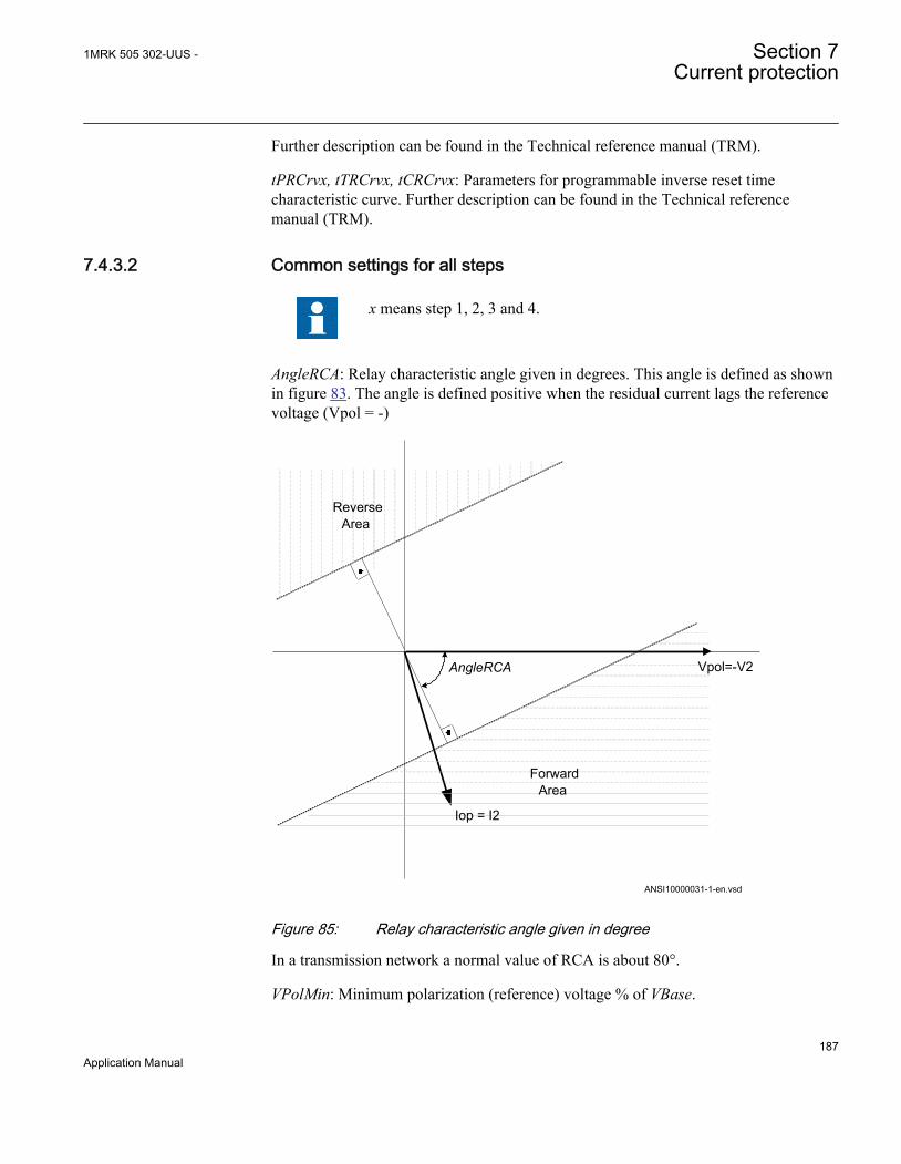
Further description can be found in the Technical reference manual (TRM).
tPRCrvx, tTRCrvx, tCRCrvx: Parameters for programmable inverse reset timecharacteristic curve. Further description can be found in the Technical referencemanual (TRM).
7.4.3.2 Common settings for all steps
x means step 1, 2, 3 and 4.
AngleRCA: Relay characteristic angle given in degrees. This angle is defined as shownin figure 83. The angle is defined positive when the residual current lags the referencevoltage (Vpol = -)
AngleRCA
ForwardArea
Iop = I2
Vpol=-V2
ReverseArea
ANSI10000031-1-en.vsdANSI10000031 V1 EN
Figure 85: Relay characteristic angle given in degree
In a transmission network a normal value of RCA is about 80°.
VPolMin: Minimum polarization (reference) voltage % of VBase.
1MRK 505 302-UUS - Section 7Current protection
187Application Manual
I>Dir: Operate residual current level for directional comparison scheme. The setting isgiven in % of IBase. The pickup forward or pickup reverse signals can be used in acommunication scheme. The appropriate signal must be configured to thecommunication scheme block.
7.5 Thermal overload protection, two time constantsTRPTTR (49)
7.5.1 IdentificationFunction description IEC 61850
identificationIEC 60617identification
ANSI/IEEE C37.2device number
Thermal overload protection, two timeconstants
TRPTTR
SYMBOL-A V1 EN
49
7.5.2 ApplicationTransformers in the power system are designed for a certain maximum load current(power) level. If the current exceeds this level the losses will be higher than expected.As a consequence the temperature of the transformer will increase. If the temperatureof the transformer reaches too high a value, the equipment might be damaged;
• The insulation within the transformer experiences forced ageing. As aconsequence of this, the risk of internal phase-to-phase or phase-to-ground faultsincreases.
• There might be hot spots within the transformer, which degrades the paperinsulation. It might also cause bubbling in the transformer oil.
In stressed situations in the power system it can be required to overload transformersfor a limited time. This should be done without the above mentioned risks. The thermaloverload protection provides information and makes temporary overloading oftransformers possible.
The permissible load level of a power transformer is highly dependent on the coolingsystem of the transformer. There are two main principles:
Section 7 1MRK 505 302-UUS -Current protection
188Application Manual

• OA: The air is naturally circulated to the coolers without fans and the oil isnaturally circulated without pumps.
• FOA: The coolers have fans to force air for cooling and pumps to force thecirculation of the transformer oil.
The protection can have two sets of parameters, one for non-forced cooling and one forforced cooling. Both the permissive steady state loading level as well as the thermaltime constant is influenced by the cooling system of the transformer. The twoparameters sets can be activated by the binary input signal COOLING. This can beused for transformers where forced cooling can be taken out of operation, for exampleat fan or pump faults.
The thermal overload protection estimates the internal heat content of the transformer(temperature) continuously. This estimation is made by using a thermal model of thetransformer which is based on current measurement.
If the heat content of the protected transformer reaches a set alarm level a signal can begiven to the operator. Two alarm levels are available. This enables preventive actionsin the power system to be taken before dangerous temperatures are reached. If thetemperature continues to increase to the trip value, the protection initiates a trip of theprotected transformer.
After tripping by the thermal overload protection, the transformer will cool down overtime. There will be a time gap before the heat content (temperature) reaches such alevel so that the transformer can be taken into service again. Therefore, the functionwill continue to estimate the heat content using a set cooling time constant. Energizingof the transformer can be blocked until the heat content has reached a set level.
7.5.3 Setting guidelineThe parameters for the thermal overload protection, two time constants (TRPTTR, 49)are set via the local HMI or Protection and Control IED Manager (PCM600).
The following settings can be done for the thermal overload protection:
Operation: Disabled/Enabled
Operation: Sets the mode of operation. Disabled switches off the complete function.
GlobalBaseSel: Selects the global base value group used by the function to define(IBase), (UBase) and (SBase).
IRef: Reference level of the current given in % of IBase. When the current is equal toIRef the final (steady state) heat content is equal to 1. It is suggested to give a settingcorresponding to the rated current of the transformer winding.
1MRK 505 302-UUS - Section 7Current protection
189Application Manual

IRefMult: If a binary input ENMULT is activated the reference current value can bemultiplied by the factor IRefMult. The activation could be used in case of deviatingambient temperature from the reference value. In the standard for loading of atransformer an ambient temperature of 20°C is used. For lower ambient temperaturesthe load ability is increased and vice versa. IRefMult can be set within a range: 0.01 -10.00.
IBase1: Base current for setting given as percentage of IBase. This setting shall berelated to the status with no COOLING input. It is suggested to give a settingcorresponding to the rated current of the transformer with natural cooling (OA).
IBase2: Base current for setting given as percentage of IBase. This setting shall berelated to the status with activated COOLING input. It is suggested to give a settingcorresponding to the rated current of the transformer with forced cooling (FOA). If thetransformer has no forced cooling IBase2 can be set equal to IBase1.
Tau1: The thermal time constant of the protected transformer, related to IBase1 (nocooling) given in minutes.
Tau2: The thermal time constant of the protected transformer, related to IBase2 (withcooling) given in minutes.
The thermal time constant should be obtained from the transformer manufacturersmanuals. The thermal time constant is dependent on the cooling and the amount of oil.Normal time constants for medium and large transformers (according to IEC 60076-7)are about 2.5 hours for naturally cooled transformers and 1.5 hours for forced cooledtransformers.
The time constant can be estimated from measurements of the oil temperature during acooling sequence (described in IEC 60076-7). It is assumed that the transformer isoperated at a certain load level with a constant oil temperature (steady state operation).The oil temperature above the ambient temperature is DQo0. Then the transformer isdisconnected from the grid (no load). After a time t of at least 30 minutes thetemperature of the oil is measured again. Now the oil temperature above the ambienttemperature is DQot. The thermal time constant can now be estimated as:
0ln lno ot
tt =DQ - DQ
EQUATION1180 V1 EN (Equation 36)
If the transformer has forced cooling (FOA) the measurement should be made bothwith and without the forced cooling in operation, giving Tau2 and Tau1.
The time constants can be changed if the current is higher than a set value or lowerthan a set value. If the current is high it is assumed that the forced cooling is activated
Section 7 1MRK 505 302-UUS -Current protection
190Application Manual
while it is deactivated at low current. The setting of the parameters below enablesautomatic adjustment of the time constant.
Tau1High: Multiplication factor to adjust the time constant Tau1 if the current ishigher than the set value IHighTau1. IHighTau1 is set in % of IBase1.
Tau1Low: Multiplication factor to adjust the time constant Tau1 if the current is lowerthan the set value ILowTau1. ILowTau1 is set in % of IBase1.
Tau2High: Multiplication factor to adjust the time constant Tau2 if the current ishigher than the set value IHighTau2. IHighTau2 is set in % of IBase2.
Tau2Low: Multiplication factor to adjust the time constant Tau2 if the current is lowerthan the set value ILowTau2. ILowTau2 is set in % of IBase2.
The possibility to change time constant with the current value as the base can be usefulin different applications. Below some examples are given:
• In case a total interruption (low current) of the protected transformer all coolingpossibilities will be inactive. This can result in a changed value of the time constant.
• If other components (motors) are included in the thermal protection, there is a riskof overheating of that equipment in case of very high current. The thermal timeconstant is often smaller for a motor than for the transformer.
ITrip: The steady state current that the transformer can withstand. The setting is givenin % of IBase1 or IBase2.
Alarm1: Heat content level for activation of the signal ALARM1. ALARM1 is set in %of the trip heat content level.
Alarm2: Heat content level for activation of the output signal ALARM2. ALARM2 isset in % of the trip heat content level.
LockoutReset: Lockout release level of heat content to release the lockout signal. Whenthe thermal overload protection trips a lock-out signal is activated. This signal isintended to block switching on of the protected circuit transformer as long as thetransformer temperature is high. The signal is released when the estimated heat contentis below the set value. This temperature value should be chosen below the alarmtemperature. LockoutReset is set in % of the trip heat content level.
ThetaInit: Heat content before activation of the function. This setting can be set a littlebelow the alarm level. If the transformer is loaded before the activation of theprotection function, its temperature can be higher than the ambient temperature. Thestart point given in the setting will prevent risk of no trip at overtemperature during thefirst moments after activation. ThetaInit: is set in % of the trip heat content level.
1MRK 505 302-UUS - Section 7Current protection
191Application Manual
Warning: If the calculated time to trip factor is below the setting Warning a warningsignal is activated. The setting is given in minutes.
7.6 Breaker failure protection 3-phase activation andoutput CCRBRF (50BF)
7.6.1 IdentificationFunction description IEC 61850
identificationIEC 60617identification
ANSI/IEEE C37.2device number
Breaker failure protection, 3-phaseactivation and output
CCRBRF
3I>BF
SYMBOL-U V1 EN
50BF
7.6.2 ApplicationIn the design of the fault clearance system the N-1 criterion is often used. This meansthat a fault needs to be cleared even if any component in the fault clearance system isfaulty. One necessary component in the fault clearance system is the circuit breaker. Itis from practical and economical reason not feasible to duplicate the circuit breaker forthe protected component. Instead a breaker failure protection is used.
Breaker failure protection, 3-phase activation and output (CCRBRF, 50BF) will issue aback-up trip command to adjacent circuit breakers in case of failure to trip of the“normal” circuit breaker for the protected component. The detection of failure to breakthe current through the breaker is made by means of current measurement or asdetection of remaining trip signal (unconditional).
CCRBRF (50BF) can also give a re-trip. This means that a second trip signal is sent tothe protected circuit breaker. The re-trip function can be used to increase theprobability of operation of the breaker, or it can be used to avoid back-up trip of manybreakers in case of mistakes during relay maintenance and test.
7.6.3 Setting guidelinesThe parameters for Breaker failure protection 3-phase activation and output CCRBRF(50BF) are set via the local HMI or PCM600.
The following settings can be done for the breaker failure protection.
Section 7 1MRK 505 302-UUS -Current protection
192Application Manual

GlobalBaseSel: Selects the global base value group used by the function to define(IBase), (VBase) and (SBase).
Operation: Disabled/Enabled
FunctionMode This parameter can be set Current or Contact. This states the way thedetection of failure of the breaker is performed. In the mode current the currentmeasurement is used for the detection. In the mode Contact the long duration ofbreaker position signal is used as indicator of failure of the breaker. The modeCurrent&Contact means that both ways of detections are activated. Contact mode canbe usable in applications where the fault current through the circuit breaker is small.This can be the case for some generator protection application (for example reversepower protection) or in case of line ends with weak end infeed.
RetripMode: This setting states how the re-trip function shall operate. Retrip Off meansthat the re-trip function is not activated. CB Pos Check (circuit breaker position check)and Current means that a phase current must be larger than the operate level to allow re-trip. CB Pos Check (circuit breaker position check) and Contact means re-trip is donewhen circuit breaker is closed (breaker position is used). No CBPos Check means re-trip is done without check of breaker position.
Table 27: Dependencies between parameters RetripMode and FunctionMode
RetripMode FunctionMode DescriptionRetrip Off N/A the re-trip function is not activated
CB Pos Check Current a phase current must be largerthan the operate level to allow re-trip
Contact re-trip is done when breakerposition indicates that breaker isstill closed after re-trip time haselapsed
Current&Contact both methods are used
No CBPos Check Current re-trip is done without check ofbreaker position
Contact re-trip is done without check ofbreaker position
Current&Contact both methods are used
BuTripMode: Back-up trip mode is given to state sufficient current criteria to detectfailure to break. For Current operation 2 out of 4 means that at least two currents, ofthe three-phase currents and the residual current, shall be high to indicate breakerfailure. 1 out of 3 means that at least one current of the three-phase currents shall behigh to indicate breaker failure. 1 out of 4 means that at least one current of the three-phase currents or the residual current shall be high to indicate breaker failure. In most
1MRK 505 302-UUS - Section 7Current protection
193Application Manual

applications 1 out of 3 is sufficient. For Contact operation means back-up trip is donewhen circuit breaker is closed (breaker position is used).
Pickup_PH: Current level for detection of breaker failure, set in % of IBase. Thisparameter should be set so that faults with small fault current can be detected. Thesetting can be chosen in accordance with the most sensitive protection function to startthe breaker failure protection. Typical setting is 10% of IBase.
Pickup_BlkCont: If any contact based detection of breaker failure is used this functioncan be blocked if any phase current is larger than this setting level. If theFunctionMode is set Current&Contact breaker failure for high current faults are safelydetected by the current measurement function. To increase security the contact basedfunction should be disabled for high currents. The setting can be given within the range5 – 200% of IBase.
Pickup_N: Residual current level for detection of breaker failure set in % of IBase. Inhigh impedance grounded systems the residual current at phase- to-ground faults arenormally much smaller than the short circuit currents. In order to detect breaker failureat single-phase-ground faults in these systems it is necessary to measure the residualcurrent separately. Also in effectively grounded systems the setting of the ground-faultcurrent protection can be chosen to relatively low current level. The BuTripMode is set1 out of 4. The current setting should be chosen in accordance to the setting of thesensitive ground-fault protection. The setting can be given within the range 2 – 200 %of IBase.
t1: Time delay of the re-trip. The setting can be given within the range 0 – 60s in stepsof 0.001 s. Typical setting is 0 – 50ms.
t2: Time delay of the back-up trip. The choice of this setting is made as short aspossible at the same time as unwanted operation must be avoided. Typical setting is 90– 200ms (also dependent of re-trip timer).
The minimum time delay for the re-trip can be estimated as:
_2 1³ + + +cbopen BFP reset margint t t t tEQUATION1430 V1 EN (Equation 37)
where:
tcbopen is the maximum opening time for the circuit breaker
tBFP_reset is the maximum time for breaker failure protection to detect correct breaker function (thecurrent criteria reset)
tmargin is a safety margin
Section 7 1MRK 505 302-UUS -Current protection
194Application Manual
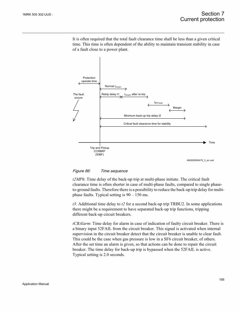
It is often required that the total fault clearance time shall be less than a given criticaltime. This time is often dependent of the ability to maintain transient stability in caseof a fault close to a power plant.
Time
The fault occurs
Protection operate time
Trip and Pickup CCRBRF (50BF)
Normal tcbopen
Margin
Retrip delay t1 tcbopen after re-trip
tBFPreset
Minimum back-up trip delay t2
Critical fault clearance time for stability
ANSI05000479_3_en.vsdANSI05000479 V3 EN
Figure 86: Time sequence
t2MPh: Time delay of the back-up trip at multi-phase initiate. The critical faultclearance time is often shorter in case of multi-phase faults, compared to single phase-to-ground faults. Therefore there is a possibility to reduce the back-up trip delay for multi-phase faults. Typical setting is 90 – 150 ms.
t3: Additional time delay to t2 for a second back-up trip TRBU2. In some applicationsthere might be a requirement to have separated back-up trip functions, trippingdifferent back-up circuit breakers.
tCBAlarm: Time delay for alarm in case of indication of faulty circuit breaker. There isa binary input 52FAIL from the circuit breaker. This signal is activated when internalsupervision in the circuit breaker detect that the circuit breaker is unable to clear fault.This could be the case when gas pressure is low in a SF6 circuit breaker, of others.After the set time an alarm is given, so that actions can be done to repair the circuitbreaker. The time delay for back-up trip is bypassed when the 52FAIL is active.Typical setting is 2.0 seconds.
1MRK 505 302-UUS - Section 7Current protection
195Application Manual

tPulse: Trip pulse duration. This setting must be larger than the critical impulse time ofcircuit breakers to be tripped from the breaker failure protection. Typical setting is 200ms.
7.7 Breaker failure protection, single phase versionCCSRBRF (50BF)
7.7.1 IdentificationFunction description IEC 61850
identificationIEC 60617identification
ANSI/IEEE C37.2device number
Breaker failure protection, single phaseversion
CCSRBRF
I>BF
SYMBOL-II V1 EN
50BF
7.7.2 ApplicationIn the design of the fault clearance system the N-1 criterion is often used. This meansthat a fault shall be cleared even if any component in the fault clearance system isfaulty. One necessary component in the fault clearance system is the circuit breaker. Itis from practical and economical reason not feasible to duplicate the circuit breaker forthe protected component. Instead a breaker failure protection is used.
Breaker failure protection, single phase version (CCSRBRF,50BF) function will issuea back-up trip command to adjacent circuit breakers in case of failure to trip of the“normal” circuit breaker for the protected component. The detection of failure to breakthe current through the breaker is made by means of current measurement or asdetection of remaining trip signal (unconditional).
CCSRBRF (50BF) function can also give a re-trip. This means that a second trip signalis sent to the protected circuit breaker. The re-trip function can be used to increase theprobability of operation of the breaker, or it can be used to avoid back-up trip of manybreakers in case of mistakes during relay maintenance and test.
7.7.3 Setting guidelinesThe parameters for Breaker failure protection, single phase version (CCSRBRF,50BF)are set via the local HMI or PCM600.
The following settings can be done for the breaker failure protection.
Section 7 1MRK 505 302-UUS -Current protection
196Application Manual
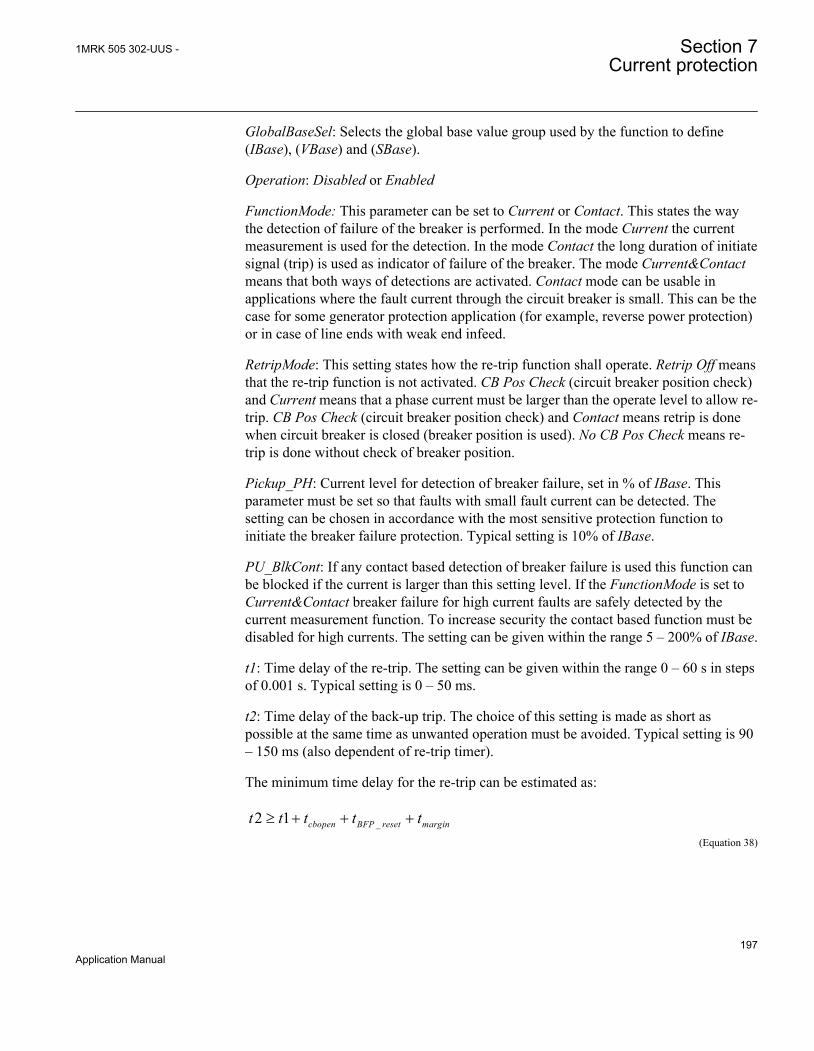
GlobalBaseSel: Selects the global base value group used by the function to define(IBase), (VBase) and (SBase).
Operation: Disabled or Enabled
FunctionMode: This parameter can be set to Current or Contact. This states the waythe detection of failure of the breaker is performed. In the mode Current the currentmeasurement is used for the detection. In the mode Contact the long duration of initiatesignal (trip) is used as indicator of failure of the breaker. The mode Current&Contactmeans that both ways of detections are activated. Contact mode can be usable inapplications where the fault current through the circuit breaker is small. This can be thecase for some generator protection application (for example, reverse power protection)or in case of line ends with weak end infeed.
RetripMode: This setting states how the re-trip function shall operate. Retrip Off meansthat the re-trip function is not activated. CB Pos Check (circuit breaker position check)and Current means that a phase current must be larger than the operate level to allow re-trip. CB Pos Check (circuit breaker position check) and Contact means retrip is donewhen circuit breaker is closed (breaker position is used). No CB Pos Check means re-trip is done without check of breaker position.
Pickup_PH: Current level for detection of breaker failure, set in % of IBase. Thisparameter must be set so that faults with small fault current can be detected. Thesetting can be chosen in accordance with the most sensitive protection function toinitiate the breaker failure protection. Typical setting is 10% of IBase.
PU_BlkCont: If any contact based detection of breaker failure is used this function canbe blocked if the current is larger than this setting level. If the FunctionMode is set toCurrent&Contact breaker failure for high current faults are safely detected by thecurrent measurement function. To increase security the contact based function must bedisabled for high currents. The setting can be given within the range 5 – 200% of IBase.
t1: Time delay of the re-trip. The setting can be given within the range 0 – 60 s in stepsof 0.001 s. Typical setting is 0 – 50 ms.
t2: Time delay of the back-up trip. The choice of this setting is made as short aspossible at the same time as unwanted operation must be avoided. Typical setting is 90– 150 ms (also dependent of re-trip timer).
The minimum time delay for the re-trip can be estimated as:
_2 1³ + + +cbopen BFP reset margint t t t tEQUATION1430 V1 EN (Equation 38)
1MRK 505 302-UUS - Section 7Current protection
197Application Manual

where:
tcbopen is the maximum opening time for the circuit breaker
tBFP_reset is the maximum time for breaker failure protection to detect correct breaker function (thecurrent criteria reset)
tmargin is a safety margin
It is often required that the total fault clearance time shall be less than a given criticaltime. This time is often dependent of the ability to maintain transient stability in caseof a fault close to a power plant.
Time
The fault occurs
Protection operate time
Trip and Pickup CCRBRF (50BF)
Normal tcbopen
Margin
Retrip delay t1 tcbopen after re-trip
tBFPreset
Minimum back-up trip delay t2
Critical fault clearance time for stability
ANSI05000479_3_en.vsdANSI05000479 V3 EN
Figure 87: Time sequence
t3: Additional time delay to t2 for a second back-up trip TRBU2. In some applicationsthere might be a requirement to have separated back-up trip functions, trippingdifferent back-up circuit breakers.
tCBAlarm: Time delay for alarm in case of indication of faulty circuit breaker. There isa binary input 52FAIL from the circuit breaker. This signal is activated when internalsupervision in the circuit breaker detect that the circuit breaker is unable to clear fault.This could be the case when gas pressure is low in a SF6 circuit breaker, of others.After the set time an alarm is given, so that actions can be done to repair the circuit
Section 7 1MRK 505 302-UUS -Current protection
198Application Manual

breaker. The time delay for back-up trip is bypassed when the 52FAIL is active.Typical setting is 2.0 seconds.
tPulse: Trip pulse duration. This setting must be larger than the critical impulse time ofcircuit breakers to be tripped from the breaker failure protection. Typical setting is 200ms.
7.8 Directional underpower protection GUPPDUP (37)
7.8.1 IdentificationFunction description IEC 61850
identificationIEC 60617identification
ANSI/IEEE C37.2device number
Directional underpower protection GUPPDUPP <
2SYMBOL-LL V2 EN
37
7.8.2 ApplicationThe task of a generator in a power plant is to convert mechanical energy available as atorque on a rotating shaft to electric energy.
Sometimes, the mechanical power from a prime mover may decrease so much that itdoes not cover bearing losses and ventilation losses. Then, the synchronous generatorbecomes a synchronous motor and starts to take electric power from the rest of thepower system. This operating state, where individual synchronous machines operate asmotors, implies no risk for the machine itself. If the generator under consideration isvery large and if it consumes lots of electric power, it may be desirable to disconnect itto ease the task for the rest of the power system.
Often, the motoring condition may imply that the turbine is in a very dangerous state.The task of the reverse power protection is to protect the turbine and not to protect thegenerator itself.
Steam turbines easily become overheated if the steam flow becomes too low or if thesteam ceases to flow through the turbine. Therefore, turbo-generators should havereverse power protection. There are several contingencies that may cause reversepower: break of a main steam pipe, damage to one or more blades in the steam turbineor inadvertent closing of the main stop valves. In the last case, it is highly desirable to
1MRK 505 302-UUS - Section 7Current protection
199Application Manual
have a reliable reverse power protection. It may prevent damage to an otherwiseundamaged plant.
During the routine shutdown of many thermal power units, the reverse powerprotection gives the tripping impulse to the generator breaker (the unit breaker). Bydoing so, one prevents the disconnection of the unit before the mechanical power hasbecome zero. Earlier disconnection would cause an acceleration of the turbinegenerator at all routine shutdowns. This should have caused overspeed and highcentrifugal stresses.
When the steam ceases to flow through a turbine, the cooling of the turbine blades willdisappear. Now, it is not possible to remove all heat generated by the windage losses.Instead, the heat will increase the temperature in the steam turbine and especially of theblades. When a steam turbine rotates without steam supply, the electric powerconsumption will be about 2% of rated power. Even if the turbine rotates in vacuum, itwill soon become overheated and damaged. The turbine overheats within minutes if theturbine loses the vacuum.
The critical time to overheating a steam turbine varies from about 0.5 to 30 minutesdepending on the type of turbine. A high-pressure turbine with small and thin bladeswill become overheated more easily than a low-pressure turbine with long and heavyblades. The conditions vary from turbine to turbine and it is necessary to ask theturbine manufacturer in each case.
Power to the power plant auxiliaries may come from a station service transformerconnected to the secondary side of the step-up transformer. Power may also come froma start-up service transformer connected to the external network. One has to design thereverse power protection so that it can detect reverse power independent of the flow ofpower to the power plant auxiliaries.
Hydro turbines tolerate reverse power much better than steam turbines do. OnlyKaplan turbine and bulb turbines may suffer from reverse power. There is a risk thatthe turbine runner moves axially and touches stationary parts. They are not alwaysstrong enough to withstand the associated stresses.
Ice and snow may block the intake when the outdoor temperature falls far below zero.Branches and leaves may also block the trash gates. A complete blockage of the intakemay cause cavitations. The risk for damages to hydro turbines can justify reversepower protection in unattended plants.
A hydro turbine that rotates in water with closed wicket gates will draw electric powerfrom the rest of the power system. This power will be about 10% of the rated power. Ifthere is only air in the hydro turbine, the power demand will fall to about 3%.
Diesel engines should have reverse power protection. The generator will take about15% of its rated power or more from the system. A stiff engine may require perhaps
Section 7 1MRK 505 302-UUS -Current protection
200Application Manual

25% of the rated power to motor it. An engine that is good run in might need no morethan 5%. It is necessary to obtain information from the engine manufacturer and tomeasure the reverse power during commissioning.
Gas turbines usually do not require reverse power protection.
Figure 88 illustrates the reverse power protection with underpower protection and withoverpower protection. The underpower protection gives a higher margin and shouldprovide better dependability. On the other hand, the risk for unwanted operationimmediately after synchronization may be higher. One should set the underpowerprotection (reference angle set to 0) to trip if the active power from the generator is lessthan about 2%. One should set the overpower protection (reference angle set to 180) totrip if the power flow from the network to the generator is higher than 1%.
Underpower protection Overpower protection
Q Q
P P
Operating point without turbine torque
Margin Margin
OperateLine
OperateLine
Operating point without turbine torque
IEC09000019-2-en.vsdIEC09000019 V2 EN
Figure 88: Reverse power protection with underpower or overpower protection
7.8.3 Setting guidelinesGlobalBaseSel: Selects the global base value group used by the function to define(IBase), (VBase) and (SBase).
Operation: With the parameter Operation the function can be set Enabled/Disabled.
Mode: The voltage and current used for the power measurement. The settingpossibilities are shown in table 28.
1MRK 505 302-UUS - Section 7Current protection
201Application Manual
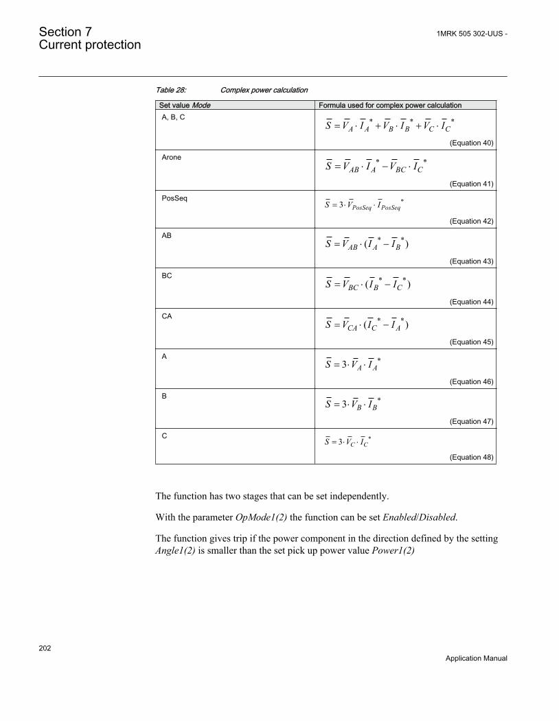
Table 28: Complex power calculation
Set value Mode Formula used for complex power calculationA, B, C * * *
A A B B C CS V I V I V I= × + × + ×
EQUATION2055-ANSI V1 EN (Equation 40)
Arone * *AB A BC CS V I V I= × - ×
EQUATION2056-ANSI V1 EN (Equation 41)
PosSeq *3 PosSeq PosSeqS V I= × ×
EQUATION2057-ANSI V1 EN (Equation 42)
AB * *( )AB A BS V I I= × -
EQUATION2058-ANSI V1 EN (Equation 43)
BC * *( )BC B CS V I I= × -
EQUATION2059-ANSI V1 EN (Equation 44)
CA * *( )CA C AS V I I= × -
EQUATION2060-ANSI V1 EN (Equation 45)
A *3 A AS V I= × ×
EQUATION2061-ANSI V1 EN (Equation 46)
B *3 B BS V I= × ×
EQUATION2062-ANSI V1 EN (Equation 47)
C *3 C CS V I= × ×
EQUATION2063-ANSI V1 EN (Equation 48)
The function has two stages that can be set independently.
With the parameter OpMode1(2) the function can be set Enabled/Disabled.
The function gives trip if the power component in the direction defined by the settingAngle1(2) is smaller than the set pick up power value Power1(2)
Section 7 1MRK 505 302-UUS -Current protection
202Application Manual
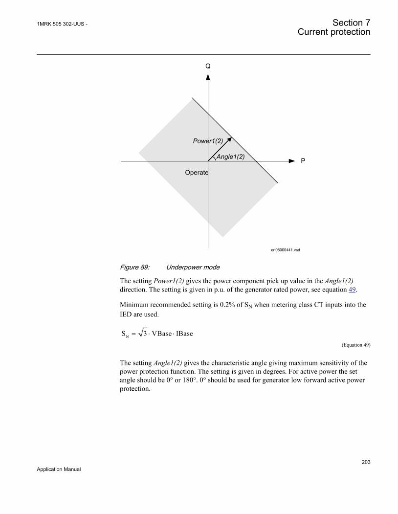
Operate
Angle1(2)
Power1(2)
P
Q
en06000441.vsdIEC06000441 V1 EN
Figure 89: Underpower mode
The setting Power1(2) gives the power component pick up value in the Angle1(2)direction. The setting is given in p.u. of the generator rated power, see equation 49.
Minimum recommended setting is 0.2% of SN when metering class CT inputs into theIED are used.
NS 3 VBase IBase= × ×EQUATION2047 V1 EN (Equation 49)
The setting Angle1(2) gives the characteristic angle giving maximum sensitivity of thepower protection function. The setting is given in degrees. For active power the setangle should be 0° or 180°. 0° should be used for generator low forward active powerprotection.
1MRK 505 302-UUS - Section 7Current protection
203Application Manual

OperateAngle1(2) = 0°
Power1(2)
P
Q
en06000556.vsdIEC06000556 V1 EN
Figure 90: For low forward power the set angle should be 0° in the underpowerfunction
TripDelay1(2) is set in seconds to give the time delay for trip of the stage after pick up.
Hysteresis1(2) is given in p.u. of generator rated power according to equation 50.
NS 3 VBase IBase= × ×EQUATION2047 V1 EN (Equation 50)
The drop out power will be Power1(2) + Hysteresis1(2).
The possibility to have low pass filtering of the measured power can be made as shownin the formula:
S TD S TD SOld Calculated
= ⋅ + −( ) ⋅1
EQUATION1893-ANSI V1 EN (Equation 51)
Where
S is a new measured value to be used for the protection function
Sold is the measured value given from the function in previous execution cycle
SCalculated is the new calculated value in the present execution cycle
TD is settable parameter
Section 7 1MRK 505 302-UUS -Current protection
204Application Manual

The value of k=0.92 is recommended in generator applications as the trip delay isnormally quite long.
The calibration factors for current and voltage measurement errors are set % of ratedcurrent/voltage:
IMagComp5, IMagComp30, IMagComp100
VMagComp5, VMagComp30, VMagComp100
IMagComp5, IMagComp30, IMagComp100
The angle compensation is given as difference between current and voltage angle errors.
The values are given for operating points 5, 30 and 100% of rated current/voltage. Thevalues should be available from instrument transformer test protocols.
7.9 Directional overpower protection GOPPDOP (32)
7.9.1 IdentificationFunction description IEC 61850
identificationIEC 60617identification
ANSI/IEEE C37.2device number
Directional overpower protection GOPPDOPP >
2DOCUMENT172362-IMG158942
V2 EN
32
7.9.2 ApplicationThe task of a generator in a power plant is to convert mechanical energy available as atorque on a rotating shaft to electric energy.
Sometimes, the mechanical power from a prime mover may decrease so much that itdoes not cover bearing losses and ventilation losses. Then, the synchronous generatorbecomes a synchronous motor and starts to take electric power from the rest of thepower system. This operating state, where individual synchronous machines operate asmotors, implies no risk for the machine itself. If the generator under consideration isvery large and if it consumes lots of electric power, it may be desirable to disconnect itto ease the task for the rest of the power system.
1MRK 505 302-UUS - Section 7Current protection
205Application Manual

Often, the motoring condition may imply that the turbine is in a very dangerous state.The task of the reverse power protection is to protect the turbine and not to protect thegenerator itself.
Steam turbines easily become overheated if the steam flow becomes too low or if thesteam ceases to flow through the turbine. Therefore, turbo-generators should havereverse power protection. There are several contingencies that may cause reversepower: break of a main steam pipe, damage to one or more blades in the steam turbineor inadvertent closing of the main stop valves. In the last case, it is highly desirable tohave a reliable reverse power protection. It may prevent damage to an otherwiseundamaged plant.
During the routine shutdown of many thermal power units, the reverse powerprotection gives the tripping impulse to the generator breaker (the unit breaker). Bydoing so, one prevents the disconnection of the unit before the mechanical power hasbecome zero. Earlier disconnection would cause an acceleration of the turbinegenerator at all routine shutdowns. This should have caused overspeed and highcentrifugal stresses.
When the steam ceases to flow through a turbine, the cooling of the turbine blades willdisappear. Now, it is not possible to remove all heat generated by the windage losses.Instead, the heat will increase the temperature in the steam turbine and especially of theblades. When a steam turbine rotates without steam supply, the electric powerconsumption will be about 2% of rated power. Even if the turbine rotates in vacuum, itwill soon become overheated and damaged. The turbine overheats within minutes if theturbine loses the vacuum.
The critical time to overheating of a steam turbine varies from about 0.5 to 30 minutesdepending on the type of turbine. A high-pressure turbine with small and thin bladeswill become overheated more easily than a low-pressure turbine with long and heavyblades. The conditions vary from turbine to turbine and it is necessary to ask theturbine manufacturer in each case.
Power to the power plant auxiliaries may come from a station service transformerconnected to the primary side of the step-up transformer. Power may also come from astart-up service transformer connected to the external network. One has to design thereverse power protection so that it can detect reverse power independent of the flow ofpower to the power plant auxiliaries.
Hydro turbines tolerate reverse power much better than steam turbines do. OnlyKaplan turbine and bulb turbines may suffer from reverse power. There is a risk thatthe turbine runner moves axially and touches stationary parts. They are not alwaysstrong enough to withstand the associated stresses.
Ice and snow may block the intake when the outdoor temperature falls far below zero.Branches and leaves may also block the trash gates. A complete blockage of the intake
Section 7 1MRK 505 302-UUS -Current protection
206Application Manual
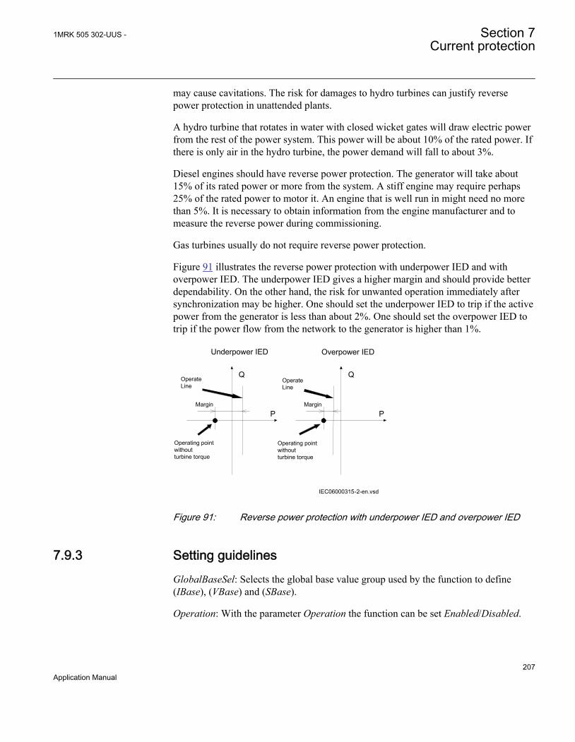
may cause cavitations. The risk for damages to hydro turbines can justify reversepower protection in unattended plants.
A hydro turbine that rotates in water with closed wicket gates will draw electric powerfrom the rest of the power system. This power will be about 10% of the rated power. Ifthere is only air in the hydro turbine, the power demand will fall to about 3%.
Diesel engines should have reverse power protection. The generator will take about15% of its rated power or more from the system. A stiff engine may require perhaps25% of the rated power to motor it. An engine that is well run in might need no morethan 5%. It is necessary to obtain information from the engine manufacturer and tomeasure the reverse power during commissioning.
Gas turbines usually do not require reverse power protection.
Figure 91 illustrates the reverse power protection with underpower IED and withoverpower IED. The underpower IED gives a higher margin and should provide betterdependability. On the other hand, the risk for unwanted operation immediately aftersynchronization may be higher. One should set the underpower IED to trip if the activepower from the generator is less than about 2%. One should set the overpower IED totrip if the power flow from the network to the generator is higher than 1%.
Underpower IED Overpower IED
Q Q
P P
Operating point without turbine torque
Margin Margin
OperateLine
OperateLine
Operating point without turbine torque
IEC06000315-2-en.vsdIEC06000315 V2 EN
Figure 91: Reverse power protection with underpower IED and overpower IED
7.9.3 Setting guidelinesGlobalBaseSel: Selects the global base value group used by the function to define(IBase), (VBase) and (SBase).
Operation: With the parameter Operation the function can be set Enabled/Disabled.
1MRK 505 302-UUS - Section 7Current protection
207Application Manual

Mode: The voltage and current used for the power measurement. The settingpossibilities are shown in table 29.
Table 29: Complex power calculation
Set value Mode Formula used for complex power calculationA,B,C * * *
A B CA B CS V I V I V I= × + × + ×EQUATION2038 V1 EN (Equation 53)
Arone * *A CAB BCS V I V I= × ×-
EQUATION2039 V1 EN (Equation 54)
PosSeq *PosSeqPosSeqS 3 V I= × ×
EQUATION2040 V1 EN (Equation 55)
A,B *A BAB
*S V (I I )= × -
EQUATION2041 V1 EN (Equation 56)
B,C *B CBC
*S V (I I )= × -
EQUATION2042 V1 EN (Equation 57)
C,A *C ACA
*S V (I I )= × -
EQUATION2043 V1 EN (Equation 58)
A *AAS 3 V I= × ×
EQUATION2044 V1 EN (Equation 59)
B *BBS 3 V I= × ×
EQUATION2045 V1 EN (Equation 60)
C *CCS 3 V I= × ×
EQUATION2046 V1 EN (Equation 61)
The function has two stages that can be set independently.
With the parameter OpMode1(2) the function can be set Enabled/Disabled.
The function gives trip if the power component in the direction defined by the settingAngle1(2) is larger than the set pick up power value Power1(2)
Section 7 1MRK 505 302-UUS -Current protection
208Application Manual

Operate
Angle1(2)
Power1(2)
P
Q
en06000440.vsdIEC06000440 V1 EN
Figure 92: Overpower mode
The setting Power1(2) gives the power component pick up value in the Angle1(2)direction. The setting is given in p.u. of the generator rated power, see equation 62.
Minimum recommended setting is 0.2% of SN when metering class CT inputs into theIED are used.
NS 3 VBase IBase= × ×EQUATION2047 V1 EN (Equation 62)
The setting Angle1(2) gives the characteristic angle giving maximum sensitivity of thepower protection function. The setting is given in degrees. For active power the setangle should be 0° or 180°. 180° should be used for generator reverse power protection.
1MRK 505 302-UUS - Section 7Current protection
209Application Manual

Operate Angle1(2 ) = 180 o
Power1(2)
P
Q
IEC06000557-2-en.vsdIEC06000557 V2 EN
Figure 93: For reverse power the set angle should be 180° in the overpower function
TripDelay1(2) is set in seconds to give the time delay for trip of the stage after pick up.
Hysteresis1(2) is given in p.u. of generator rated power according to equation 63.
NS 3 VBase IBase= × ×EQUATION2047 V1 EN (Equation 63)
The drop out power will be Power1(2) - Hysteresis1(2).
The possibility to have low pass filtering of the measured power can be made as shownin the formula:
Section 7 1MRK 505 302-UUS -Current protection
210Application Manual

S TD S TD SOld Calculated
= ⋅ + −( ) ⋅1
EQUATION1893-ANSI V1 EN (Equation 64)
Where
S is a new measured value to be used for the protection function
Sold is the measured value given from the function in previous execution cycle
SCalculated is the new calculated value in the present execution cycle
TD is settable parameter
The value of TD=0.92 is recommended in generator applications as the trip delay isnormally quite long.
The calibration factors for current and voltage measurement errors are set % of ratedcurrent/voltage:
IMagComp5, IMagComp30, IMagComp100
VMagComp5, VMagComp30, VMagComp100
IAngComp5, IAngComp30, IAngComp100
The angle compensation is given as difference between current and voltage angle errors.
The values are given for operating points 5, 30 and 100% of rated current/voltage. Thevalues should be available from instrument transformer test protocols.
7.10 Capacitor bank protection CBPGAPC
7.10.1 IdentificationFunction description IEC 61850
identificationIEC 60617
identificationANSI/IEEE C37.2
device numberCapacitor bank protection CBPGAPC - -
7.10.2 ApplicationShunt capacitor banks (SCBs) are somewhat specific and different from other powersystem elements. These specific features of SCB are briefly summarized in this section.
1MRK 505 302-UUS - Section 7Current protection
211Application Manual

A capacitor unit is the building block used for SCB construction. The capacitor unit ismade up of individual capacitor elements, arranged in parallel or series connections.Capacitor elements normally consist of aluminum foil, paper, or film-insulated cellsimmersed in a biodegradable insulating fluid and are sealed in a metallic container. Theinternal discharge resistor is also integrated within the capacitor unit in order to reducetrapped residual voltage after disconnection of the SCB from the power system. Unitsare available in a variety of voltage ratings (240V to 25kV) and sizes (2.5kVAr toabout 1000kVAr). Capacitor unit can be designed with one or two bushings.
The high-voltage SCB is normally constructed using individual capacitor unitsconnected in series and/or parallel to obtain the required voltage and MVAr rating.Typically the neighboring capacitor units are mounted in racks. Each rack must beinsulated from the other by insulators because the can casing within each rack are at acertain potential. Refer figure 94 for an example:
Section 7 1MRK 505 302-UUS -Current protection
212Application Manual
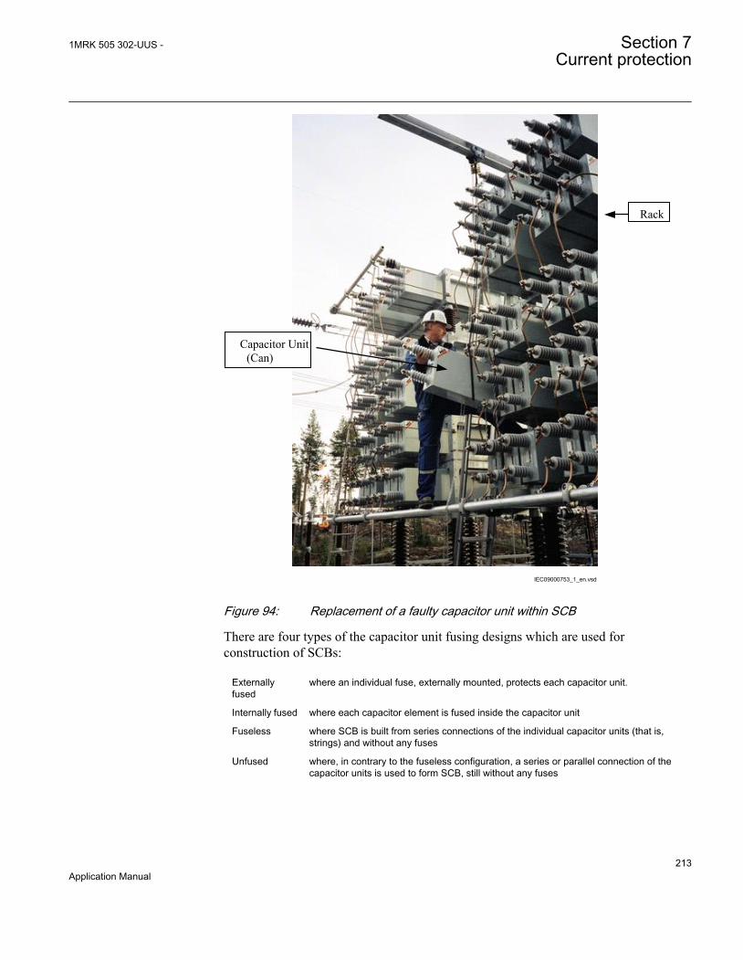
Capacitor Unit (Can)
Rack
IEC09000753_1_en.vsd
IEC09000753 V1 EN
Figure 94: Replacement of a faulty capacitor unit within SCB
There are four types of the capacitor unit fusing designs which are used forconstruction of SCBs:
Externallyfused
where an individual fuse, externally mounted, protects each capacitor unit.
Internally fused where each capacitor element is fused inside the capacitor unit
Fuseless where SCB is built from series connections of the individual capacitor units (that is,strings) and without any fuses
Unfused where, in contrary to the fuseless configuration, a series or parallel connection of thecapacitor units is used to form SCB, still without any fuses
1MRK 505 302-UUS - Section 7Current protection
213Application Manual

Which type of fusing is used may depend on can manufacturer or utility preference andprevious experience.
Because the SCBs are built from the individual capacitor units the overall connectionsmay vary. Typically used SCB configurations are:
1. Delta-connected banks (generally used only at distribution voltages)2. Single wye-connected banks3. Double wye-connected banks4. H-configuration, where each phase is connected in a bridge
Additionally, the SCB star point, when available, can be either grounded , groundedvia impedance or isolated from ground. Which type of SCB grounding is used dependson voltage level, used circuit breaker, utility preference and previous experience. Manyutilities have standard system grounding principle to ground neutrals of SCB above100 kV.
Switching of SCB will produce transients in power system. The transient inrush currentduring SCB energizing typically has high frequency components and can reach peakcurrent values, which are multiples of SCB rating. Opening of capacitor bank circuitbreaker may produce step recovery voltages across open CB contact, which canconsequently cause restrikes upon the first interruption of capacitive current. In modernpower system the synchronized CB closing/opening may be utilized in such a mannerthat transients caused by SCB switching are avoided.
7.10.2.1 SCB protection
IED protection of shunt capacitor banks requires an understanding of the capabilitiesand limitations of the individual capacitor units and associated electrical equipment.Different types of shunt capacitor bank fusing, configuration or grounding may affectthe IED selection for the protection scheme. Availability and placement of CTs andVTs can be additional limiting factor during protection scheme design.
SCB protection schemes are provided in order to detect and clear faults within thecapacitor bank itself or in the connected leads to the substation busbar. Bank protectionmay include items such as a means to disconnect a faulted capacitor unit or capacitorelement(s), a means to initiate a shutdown of the bank in case of faults that may lead toa catastrophic failure and alarms to indicate unbalance within the bank.
Capacitor bank outages and failures are often caused by accidental contact by animals.Vermin, monkeys, birds, may use the SCB as a resting place or a landing site. Whenthe animal touches the HV live parts this can result in a flash-over, can rapture or acascading failures that might cause extensive damages, fire or even total destruction ofthe whole SCB, unless the bank is sufficiently fitted with protection IEDs.
Section 7 1MRK 505 302-UUS -Current protection
214Application Manual

In addition, to fault conditions SCB can be exposed to different types of abnormaloperating conditions. In accordance with IEC and ANSI standards capacitors shall becapable of continuous operation under contingency system and bank conditions,provided the following limitations are not exceeded:
1. Capacitor units should be capable of continuous operation including harmonics,but excluding transients, to 110% of rated IED root-mean-square (RMS) voltageand a crest voltage not exceeding of rated RMS voltage. The capacitor should alsobe able to carry 135% of nominal current. The voltage capability of any serieselement of a capacitor unit shall be considered to be its share of the total capacitorunit voltage capability.
2. Capacitor units should not give less than 100% nor more than 110% of ratedreactive power at rated sinusoidal voltage and frequency, measured at a uniformcase and internal temperature of 25°C.
3. Capacitor units mounted in multiple rows and tiers should be designed forcontinuous operation for a 24h average temperature of 40 °C during the hottestday, or −40 °C during the coldest day expected at the location.
4. Capacitor units should be suitable for continuous operation at up to 135% of ratedreactive power caused by the combined effects of:• Voltage in excess of the nameplate rating at fundamental frequency, but not
over 110% of rated RMS voltage• Harmonic voltages superimposed on the fundamental frequency• Reactive power manufacturing tolerance of up to 115% of rated reactive power
5. Capacitor units rated above 600 V shall have an internal discharge device toreduce the residual voltage to 50 V or less in 5 or 10 minutes (depending onnational standard).
Note that capacitor units designed for special applications can exceed these ratings.
Thus, as a general rule, the minimum number of capacitor units connected in parallelwithin a SCB is such that isolation of one capacitor unit in a group should not cause avoltage unbalance sufficient to place more than 110% of rated voltage on theremaining capacitors of that parallel group. Equally, the minimum number of seriesconnected groups within a SCB is such that complete bypass of one group should notpause voltage higher than 110% of the rated voltage on the remaining capacitors of thatserial group. The value of 110% is the maximum continuous overvoltage capability ofcapacitor units as per IEEE Std 18-1992.
The SCB typically requires the following types of IED protection:
1MRK 505 302-UUS - Section 7Current protection
215Application Manual
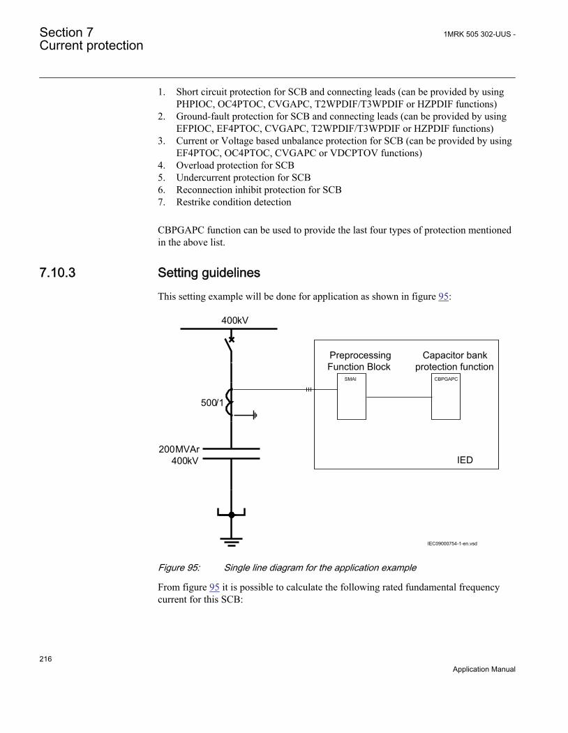
1. Short circuit protection for SCB and connecting leads (can be provided by usingPHPIOC, OC4PTOC, CVGAPC, T2WPDIF/T3WPDIF or HZPDIF functions)
2. Ground-fault protection for SCB and connecting leads (can be provided by usingEFPIOC, EF4PTOC, CVGAPC, T2WPDIF/T3WPDIF or HZPDIF functions)
3. Current or Voltage based unbalance protection for SCB (can be provided by usingEF4PTOC, OC4PTOC, CVGAPC or VDCPTOV functions)
4. Overload protection for SCB5. Undercurrent protection for SCB6. Reconnection inhibit protection for SCB7. Restrike condition detection
CBPGAPC function can be used to provide the last four types of protection mentionedin the above list.
7.10.3 Setting guidelinesThis setting example will be done for application as shown in figure 95:
Preprocessing Function Block
Capacitor bank protection function
400kV
CBPGAPCSMAI
200MVAr400kV
500/1
IED
IEC09000754-1-en.vsdIEC09000754 V1 EN
Figure 95: Single line diagram for the application example
From figure 95 it is possible to calculate the following rated fundamental frequencycurrent for this SCB:
Section 7 1MRK 505 302-UUS -Current protection
216Application Manual

1000 200[ ] 2893 400[ ]r
MVArI AkV
×= =
×IEC09000755 V1 EN (Equation 65)
or on the secondary CT side:
_ ec
289 0.578500 1r S
AI A= =
IEC09000756 V1 EN (Equation 66)
Note that the SCB rated current on the secondary CT side is important for secondaryinjection of the function.
The parameters for the Capacitor bank protection function CBPGAPC are set via thelocal HMI or PCM600. The following settings are done for this function:
General Settings:
Operation =Enabled; to enable the function
IBase =289A; Fundamental frequency SCB rated current in primary amperes. Thisvalue is used as a base value for pickup settings of all other features integrated in thisfunction.
Reconnection inhibit feature:
OperationRecIn =Enabled; to enable this feature
IRecInhibit =10% (of IBase); Current level under which function will detect that SCBis disconnected from the power system
tReconnInhibit =300s; Time period under which SCB shall discharge remainingresidual voltage to less than 5%.
Overcurrent feature:
OperationOC =Enabled; to enable this feature
PU 51 =135% (of IBase); Current level for overcurrent pickup. Selected value givespickup recommended by international standards.
tOC =30s; Time delay for overcurrent trip
Undercurrent feature:
Operation37 =Enabled; to enable this feature
1MRK 505 302-UUS - Section 7Current protection
217Application Manual
PU_37 =70% (of IBase); Current level for undercurrent pickup
tUC =5s; Time delay for undercurrent trip
Undercurrent feature is blocked by operation of Reconnection inhibitfeature.
Reactive power overload feature:
Operation QOL =Enabled; to enable this feature
UP_QOL =130% (of SCB MVAr rating); Reactive power level required for pickup.Selected value gives pickup recommended by international standards.
tQOL =60s; Time delay for reactive power overload trip
Harmonic voltage overload feature:
OperationHOL =Enabled; to enable this feature
Settings for definite time delay step
HOL_DT_V =200% (of SCB voltage rating); Voltage level required for pickup
tHOL_DT =10s; Definite time delay for harmonic overload trip
Settings for IDMT delay step
PU_HOL_DT_V =110% (of SCB voltage rating); Voltage level required for pickup ofIDMT stage. Selected value gives pickup recommended by international standards.
k_HOL_IDMT =1.0; Time multiplier for IDMT stage. Selected value gives operatetime in accordance with international standards
tMax_HOL_IDMT =2000s; Maximum time delay for IDMT stage for very low level ofharmonic overload
tMin_HOL_IDMT =0.1s; Minimum time delay for IDMT stage. Selected value givesoperate time in accordance with international standards
7.10.3.1 Restrike detection
Opening of SCBs can be quite problematic for certain types of circuit breakers (CBs).Typically such problems are manifested as CB restrikes.
In simple words this means that the CB is not breaking the current at the first zerocrossing after separation of the CB contacts. Instead current is re-ignited and only
Section 7 1MRK 505 302-UUS -Current protection
218Application Manual

braked at consecutive current zero crossings. This condition is manifested as highcurrent pulses at the moment of current re-ignition.
To detect this CB condition, the built in overcurrent feature can be used. Simply, anystart of the overcurrent feature during breaker normal opening means a restrike.Therefore simple logic can be created in the Application Configuration tool to detectsuch CB behavior. Such CB condition can be just alarmed, and if required, the built indisturbance recorder can also be triggered.
To create this logic, a binary signal that the CB is going to be opened (but not tripcommand) shall be made available to the IED.
1MRK 505 302-UUS - Section 7Current protection
219Application Manual

220

Section 8 Voltage protection
8.1 Two step undervoltage protection UV2PTUV (27)
8.1.1 IdentificationFunction description IEC 61850
identificationIEC 60617identification
ANSI/IEEE C37.2device number
Two step undervoltage protection UV2PTUV
3U<
SYMBOL-R-2U-GREATER-THANV2 EN
27
8.1.2 Setting guidelinesAll the voltage conditions in the system where UV2PTUV (27) performs its functionsshould be considered. The same also applies to the associated equipment, its voltageand time characteristic.
There is a very wide application area where general undervoltage functions are used.All voltage related settings are made as a percentage of the settings base voltage VBaseand base current IBase, which normally is set to the primary rated voltage level (phase-to-phase) of the power system or the high voltage equipment under consideration.
The setting for UV2PTUV (27) is normally not critical, since there must be enoughtime available for the main protection to clear short circuits andground faults.
Some applications and related setting guidelines for the voltage level are described inthe following sections.
8.1.2.1 Equipment protection, such as for motors and generators
The setting must be below the lowest occurring "normal" voltage and above the lowestacceptable voltage for the equipment.
1MRK 505 302-UUS - Section 8Voltage protection
221Application Manual

8.1.2.2 Disconnected equipment detection
The setting must be below the lowest occurring "normal" voltage and above the highestoccurring voltage, caused by inductive or capacitive coupling, when the equipment isdisconnected.
8.1.2.3 Power supply quality
The setting must be below the lowest occurring "normal" voltage and above the lowestacceptable voltage, due to regulation, good practice or other agreements.
8.1.2.4 Voltage instability mitigation
This setting is very much dependent on the power system characteristics, and thoroughstudies have to be made to find the suitable levels.
8.1.2.5 Backup protection for power system faults
The setting must be below the lowest occurring "normal" voltage and above the highestoccurring voltage during the fault conditions under consideration.
8.1.2.6 Settings for Two step undervoltage protection
The following settings can be done for Two step undervoltage protection UV2PTUV(27):
ConnType: Sets whether the measurement shall be phase-to-ground fundamental value,phase-to-phase fundamental value, phase-to-ground RMS value or phase-to-phaseRMS value.
Operation: Disabled or Enabled.
VBase (given in GlobalBaseSel): Base voltage phase-to-phase in primary kV. Thisvoltage is used as reference for voltage setting. UV2PTUV (27) measures selectivelyphase-to-ground voltages, or phase-to-phase voltage chosen by the setting ConnType.The function will operate if the voltage gets lower than the set percentage of VBase.When ConnType is set to PhN DFT or PhN RMS then the IED automatically dividesset value for VBase by √3. VBase is used when ConnType is set to PhPh DFT or PhPhRMS. Therefore, always set VBase as rated primary phase-to-phase voltage of theprotected object. This means operation for phase-to-ground voltage under:
(%) ( )3
< ×V VBase kV
EQUATION1711 V1 EN (Equation 67)
Section 8 1MRK 505 302-UUS -Voltage protection
222Application Manual

and operation for phase-to-phase voltage under:
Vpickup (%) VBase(kV)< ×EQUATION1991-ANSI V1 EN (Equation 68)
The below described setting parameters are identical for the two steps (n = 1 or 2).Therefore, the setting parameters are described only once.
Characteristicn: This parameter gives the type of time delay to be used. The settingcan be Definite time, Inverse Curve A, Inverse Curve B, Prog. inv. curve. The selectionis dependent on the protection application.
OpModen: This parameter describes how many of the three measured voltages thatshould be below the set level to give operation for step n. The setting can be 1 out of 3,2 out of 3 or 3 out of 3. In most applications, it is sufficient that one phase voltage islow to give operation. If UV2PTUV (27) shall be insensitive for single phase-to-ground faults, 2 out of 3 can be chosen. In subtransmission and transmission networksthe undervoltage function is mainly a system supervision function and 3 out of 3 isselected.
Pickupn: Set operate undervoltage operation value for step n, given as % of theparameter VBase. The setting is highly dependent of the protection application. It isessential to consider the minimum voltage at non-faulted situations. Normally thisvoltage is larger than 90% of nominal voltage.
tn: time delay of step n, given in s. This setting is dependent of the protectionapplication. In many applications the protection function shall not directly trip whenthere is a short circuit or ground faults in the system. The time delay must becoordinated to the short circuit protections.
tResetn: Reset time for step n if definite time delay is used, given in s. The defaultvalue is 25 ms.
tnMin: Minimum operation time for inverse time characteristic for step n, given in s.When using inverse time characteristic for the undervoltage function during very lowvoltages can give a short operation time. This might lead to unselective trip. By settingt1Min longer than the operation time for other protections such unselective tripping canbe avoided.
ResetTypeCrvn: This parameter for inverse time characteristic can be set toInstantaneous, Frozen time, Linearly decreased. The default setting isInstantaneous.
tIResetn: Reset time for step n if inverse time delay is used, given in s. The defaultvalue is 25 ms.
1MRK 505 302-UUS - Section 8Voltage protection
223Application Manual
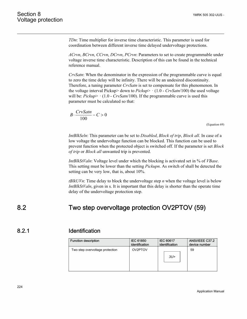
TDn: Time multiplier for inverse time characteristic. This parameter is used forcoordination between different inverse time delayed undervoltage protections.
ACrvn, BCrvn, CCrvn, DCrvn, PCrvn: Parameters to set to create programmable undervoltage inverse time characteristic. Description of this can be found in the technicalreference manual.
CrvSatn: When the denominator in the expression of the programmable curve is equalto zero the time delay will be infinity. There will be an undesired discontinuity.Therefore, a tuning parameter CrvSatn is set to compensate for this phenomenon. Inthe voltage interval Pickup> down to Pickup> · (1.0 - CrvSatn/100) the used voltagewill be: Pickup> · (1.0 - CrvSatn/100). If the programmable curve is used thisparameter must be calculated so that:
0100
CrvSatnB C× - >
EQUATION1448 V1 EN (Equation 69)
IntBlkSeln: This parameter can be set to Disabled, Block of trip, Block all. In case of alow voltage the undervoltage function can be blocked. This function can be used toprevent function when the protected object is switched off. If the parameter is set Blockof trip or Block all unwanted trip is prevented.
IntBlkStValn: Voltage level under which the blocking is activated set in % of VBase.This setting must be lower than the setting Pickupn. As switch of shall be detected thesetting can be very low, that is, about 10%.
tBlkUVn: Time delay to block the undervoltage step n when the voltage level is belowIntBlkStValn, given in s. It is important that this delay is shorter than the operate timedelay of the undervoltage protection step.
8.2 Two step overvoltage protection OV2PTOV (59)
8.2.1 IdentificationFunction description IEC 61850
identificationIEC 60617identification
ANSI/IEEE C37.2device number
Two step overvoltage protection OV2PTOV
3U>
SYMBOL-C-2U-SMALLER-THANV2 EN
59
Section 8 1MRK 505 302-UUS -Voltage protection
224Application Manual

8.2.2 ApplicationTwo step overvoltage protection OV2PTOV (59) is applicable in all situations, wherereliable detection of high voltage is necessary. OV2PTOV (59) is used for supervisionand detection of abnormal conditions, which, in combination with other protectionfunctions, increase the security of a complete protection system.
High overvoltage conditions are caused by abnormal situations in the power system.OV2PTOV (59) is applied to power system elements, such as generators, transformers,motors and power lines in order to detect high voltage conditions. OV2PTOV (59) isused in combination with low current signals, to identify a transmission line, open inthe remote end. In addition to that, OV2PTOV (59) is also used to initiate voltagecorrection measures, like insertion of shunt reactors, to compensate for low load, andthereby decreasing the voltage. The function has a high measuring accuracy andhysteresis setting to allow applications to control reactive load.
OV2PTOV (59) is used to disconnect apparatuses, like electric motors, which will bedamaged when subject to service under high voltage conditions. It deals with highvoltage conditions at power system frequency, which can be caused by:
1. Different kinds of faults, where a too high voltage appears in a certain powersystem, like metallic connection to a higher voltage level (broken conductorfalling down to a crossing overhead line, transformer flash over fault from the highvoltage winding to the low voltage winding and so on).
2. Malfunctioning of a voltage regulator or wrong settings under manual control(symmetrical voltage decrease).
3. Low load compared to the reactive power generation (symmetrical voltage decrease).4. Ground-faults in high impedance grounded systems causes, beside the high
voltage in the neutral, high voltages in the two non-faulted phases, (unsymmetricalvoltage increase).
OV2PTOV (59) prevents sensitive equipment from running under conditions thatcould cause their overheating or stress of insulation material, and, thus, shorten theirlife time expectancy. In many cases, it is a useful function in circuits for local orremote automation processes in the power system.
8.2.3 Setting guidelinesThe parameters for Two step overvoltage protection (OV2PTOV ,59) are set via thelocal HMI or PCM600.
All the voltage conditions in the system where OV2PTOV (59) performs its functionsshould be considered. The same also applies to the associated equipment, its voltageand time characteristic.
1MRK 505 302-UUS - Section 8Voltage protection
225Application Manual
There is a very wide application area where general overvoltage functions are used. Allvoltage related settings are made as a percentage of a settable base primary voltage,which normally is set to the nominal voltage level (phase-to-phase) of the powersystem or the high voltage equipment under consideration.
The time delay for the OV2PTOV (59) can sometimes be critical and related to the sizeof the overvoltage - a power system or a high voltage component can withstand smallerovervoltages for some time, but in case of large overvoltages the related equipmentshould be disconnected more rapidly.
Some applications and related setting guidelines for the voltage level are given below:
The hysteresis is for overvoltage functions very important to prevent that a transientvoltage over set level is not “sealed-in” due to a high hysteresis. Typical values shouldbe ≤ 0.5%.
8.2.3.1 Equipment protection, such as for motors, generators, reactors andtransformers
High voltage will cause overexcitation of the core and deteriorate the windinginsulation. The setting has to be well above the highest occurring "normal" voltage andwell below the highest acceptable voltage for the equipment.
8.2.3.2 Equipment protection, capacitors
High voltage will deteriorate the dielectricum and the insulation. The setting has to bewell above the highest occurring "normal" voltage and well below the highestacceptable voltage for the capacitor.
8.2.3.3 Power supply quality
The setting has to be well above the highest occurring "normal" voltage and below thehighest acceptable voltage, due to regulation, good practice or other agreements.
8.2.3.4 High impedance grounded systems
In high impedance grounded systems, ground-faults cause a voltage increase in the non-faulty phases. Two step overvoltage protection (OV2PTOV, 59) is used to detect suchfaults. The setting must be above the highest occurring "normal" voltage and below thelowest occurring voltage during faults. A metallic single-phase ground-fault causes thenon-faulted phase voltages to increase a factor of √3.
Section 8 1MRK 505 302-UUS -Voltage protection
226Application Manual

8.2.3.5 The following settings can be done for the two step overvoltage protection
ConnType: Sets whether the measurement shall be phase-to-ground fundamental value,phase-to-phase fundamental value, phase-to-ground RMS value or phase-to-phaseRMS value.
Operation: Disabled/Enabled.
VBase (given in GlobalBaseSel): Base voltage phase to phase in primary kV. Thisvoltage is used as reference for voltage setting. OV2PTOV (59) measures selectivelyphase-to-ground voltages, or phase-to-phase voltage chosen by the setting ConnType.The function will operate if the voltage gets lower than the set percentage of VBase.When ConnType is set to PhN DFT or PhN RMS then the IED automatically dividesset value for VBase by √3. When ConnType is set to PhPh DFT or PhPh RMS then setvalue for VBase is used. Therefore, always set VBase as rated primary phase-to-phaseground voltage of the protected object. If phase to neutral (PhN) measurement isselected as setting, the operation of phase-to-earth over voltage is automaticallydivided by sqrt3. This means operation for phase-to-ground voltage over:
(%) ( ) / 3V VBase kV> ×EQUATION1713 V2 EN (Equation 70)
and operation for phase-to-phase voltage over:
Vpickup (%) VBase(kV)> ×EQUATION1992-ANSI V1 EN (Equation 71)
The below described setting parameters are identical for the two steps (n = 1 or 2).Therefore the setting parameters are described only once.
Characteristicn: This parameter gives the type of time delay to be used. The settingcan be Definite time, Inverse Curve A, Inverse Curve B, Inverse Curve C or I/Prog. inv.curve. The choice is highly dependent of the protection application.
OpModen: This parameter describes how many of the three measured voltages thatshould be above the set level to give operation. The setting can be 1 out of 3, 2 out of 3,3 out of 3. In most applications it is sufficient that one phase voltage is high to giveoperation. If the function shall be insensitive for single phase-to-ground faults 1 out of3 can be chosen, because the voltage will normally rise in the non-faulted phases atsingle phase-to-ground faults. In subtransmission and transmission networks the UVfunction is mainly a system supervision function and 3 out of 3 is selected.
Pickupn: Set operate overvoltage operation value for step n, given as % of VBase. Thesetting is highly dependent of the protection application. Here it is essential to consider
1MRK 505 302-UUS - Section 8Voltage protection
227Application Manual
the maximum voltage at non-faulted situations. Normally this voltage is less than110% of nominal voltage.
tn: time delay of step n, given in s. The setting is highly dependent of the protectionapplication. In many applications the protection function is used to prevent damages tothe protected object. The speed might be important for example in case of protection oftransformer that might be overexcited. The time delay must be co-ordinated with otherautomated actions in the system.
tResetn: Reset time for step n if definite time delay is used, given in s. The defaultvalue is 25 ms.
tnMin: Minimum operation time for inverse time characteristic for step n, given in s.For very high voltages the overvoltage function, using inverse time characteristic, cangive very short operation time. This might lead to unselective trip. By setting t1Minlonger than the operation time for other protections such unselective tripping can beavoided.
ResetTypeCrvn: This parameter for inverse time characteristic can be set:Instantaneous, Frozen time, Linearly decreased. The default setting is Instantaneous.
tIResetn: Reset time for step n if inverse time delay is used, given in s. The defaultvalue is 25 ms.
TDn: Time multiplier for inverse time characteristic. This parameter is used for co-ordination between different inverse time delayed undervoltage protections.
ACrvn, BCrvn, CCrvn, DCrvn, PCrvn: Parameters to set to create programmable undervoltage inverse time characteristic. Description of this can be found in the technicalreference manual.
CrvSatn: When the denominator in the expression of the programmable curve is equalto zero the time delay will be infinity. There will be an undesired discontinuity.Therefore a tuning parameter CrvSatn is set to compensate for this phenomenon. In thevoltage interval Pickup> up to Pickup> · (1.0 + CrvSatn/100) the used voltage will be:Pickup> · (1.0 + CrvSatn/100). If the programmable curve is used, this parameter mustbe calculated so that:
0100
CrvSatnB C× - >
EQUATION1448 V1 EN (Equation 72)
HystAbsn: Absolute hysteresis set in % of VBase. The setting of this parameter ishighly dependent of the application. If the function is used as control for automaticswitching of reactive compensation devices the hysteresis must be set smaller than thevoltage change after switching of the compensation device.
Section 8 1MRK 505 302-UUS -Voltage protection
228Application Manual
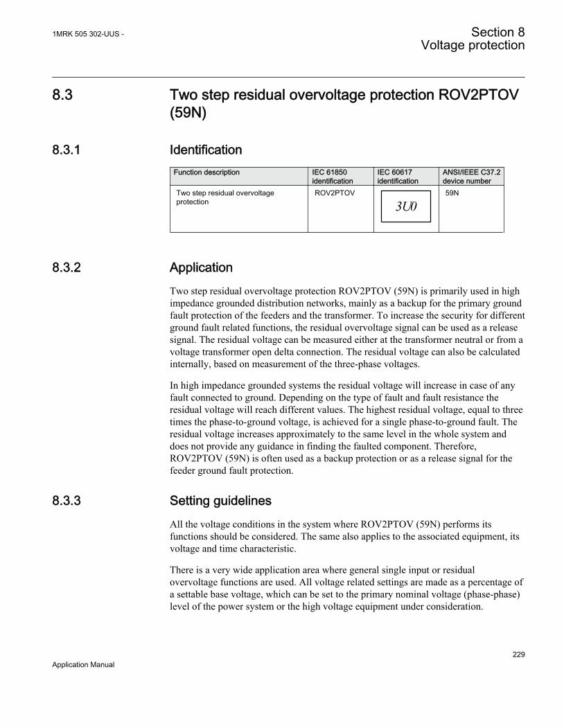
8.3 Two step residual overvoltage protection ROV2PTOV(59N)
8.3.1 IdentificationFunction description IEC 61850
identificationIEC 60617identification
ANSI/IEEE C37.2device number
Two step residual overvoltageprotection
ROV2PTOV
3U0TRV V1 EN
59N
8.3.2 ApplicationTwo step residual overvoltage protection ROV2PTOV (59N) is primarily used in highimpedance grounded distribution networks, mainly as a backup for the primary groundfault protection of the feeders and the transformer. To increase the security for differentground fault related functions, the residual overvoltage signal can be used as a releasesignal. The residual voltage can be measured either at the transformer neutral or from avoltage transformer open delta connection. The residual voltage can also be calculatedinternally, based on measurement of the three-phase voltages.
In high impedance grounded systems the residual voltage will increase in case of anyfault connected to ground. Depending on the type of fault and fault resistance theresidual voltage will reach different values. The highest residual voltage, equal to threetimes the phase-to-ground voltage, is achieved for a single phase-to-ground fault. Theresidual voltage increases approximately to the same level in the whole system anddoes not provide any guidance in finding the faulted component. Therefore,ROV2PTOV (59N) is often used as a backup protection or as a release signal for thefeeder ground fault protection.
8.3.3 Setting guidelinesAll the voltage conditions in the system where ROV2PTOV (59N) performs itsfunctions should be considered. The same also applies to the associated equipment, itsvoltage and time characteristic.
There is a very wide application area where general single input or residualovervoltage functions are used. All voltage related settings are made as a percentage ofa settable base voltage, which can be set to the primary nominal voltage (phase-phase)level of the power system or the high voltage equipment under consideration.
1MRK 505 302-UUS - Section 8Voltage protection
229Application Manual

The time delay for ROV2PTOV (59N) is seldom critical, since residual voltage isrelated to ground faults in a high impedance grounded system, and enough time mustnormally be given for the primary protection to clear the fault. In some more specificsituations, where the single overvoltage protection is used to protect some specificequipment, the time delay is shorter.
Some applications and related setting guidelines for the residual voltage level are givenbelow.
8.3.3.1 Equipment protection, such as for motors, generators, reactors andtransformers
High residual voltage indicates ground fault in the system, perhaps in the component towhich Two step residual overvoltage protection (ROV2PTOV, 59N) is connected. Forselectivity reasons to the primary protection for the faulted device ROV2PTOV (59N)must trip the component with some time delay. The setting must be above the highestoccurring "normal" residual voltage and below the highest acceptable residual voltagefor the equipment
8.3.3.2 Equipment protection, capacitors
High voltage will deteriorate the dielectric and the insulation. Two step residualovervoltage protection (ROV2PTOV, 59N) has to be connected to a neutral or opendelta winding. The setting must be above the highest occurring "normal" residualvoltage and below the highest acceptable residual voltage for the capacitor.
8.3.3.3 Power supply quality
The setting must be above the highest occurring "normal" residual voltage and belowthe highest acceptable residual voltage, due to regulation, good practice or otheragreements.
8.3.3.4 High impedance grounded systems
In high impedance grounded systems, ground faults cause a neutral voltage in thefeeding transformer neutral. Two step residual overvoltage protection ROV2PTOV(59N) is used to trip the transformer, as a backup protection for the feeder ground faultprotection, and as a backup for the transformer primary ground fault protection. Thesetting must be above the highest occurring "normal" residual voltage, and below thelowest occurring residual voltage during the faults under consideration. A metallic single-phase ground fault causes a transformer neutral to reach a voltage equal to the nominalphase-to-ground voltage.
Section 8 1MRK 505 302-UUS -Voltage protection
230Application Manual

The voltage transformers measuring the phase-to-ground voltages measure zerovoltage in the faulty phase. The two healthy phases will measure full phase-to-phasevoltage, as the faulty phase will be connected to ground. The residual overvoltage willbe three times the phase-to-ground voltage. See figure 96.
3V0
V_A
V_BV_C
V_BFV_
C F
V_C F
ANSI07000190-1-en.vsdANSI07000190 V1 EN
Figure 96: Ground fault in Non-effectively grounded systems
1MRK 505 302-UUS - Section 8Voltage protection
231Application Manual
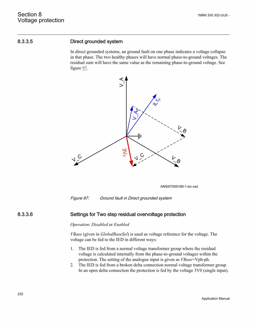
8.3.3.5 Direct grounded system
In direct grounded systems, an ground fault on one phase indicates a voltage collapsein that phase. The two healthy phases will have normal phase-to-ground voltages. Theresidual sum will have the same value as the remaining phase-to-ground voltage. Seefigure 97.
V_A
V_BV_C
V_A F
IL1 F
V_B
V_C
3V0
ANSI07000189-1-en.vsdANSI07000189 V1 EN
Figure 97: Ground fault in Direct grounded system
8.3.3.6 Settings for Two step residual overvoltage protection
Operation: Disabled or Enabled
VBase (given in GlobalBaseSel) is used as voltage reference for the voltage. Thevoltage can be fed to the IED in different ways:
1. The IED is fed from a normal voltage transformer group where the residualvoltage is calculated internally from the phase-to-ground voltages within theprotection. The setting of the analogue input is given as VBase=Vph-ph.
2. The IED is fed from a broken delta connection normal voltage transformer group.In an open delta connection the protection is fed by the voltage 3V0 (single input).
Section 8 1MRK 505 302-UUS -Voltage protection
232Application Manual

The Setting chapter in the application manual explains how the analog input needsto be set.
3. The IED is fed from a single voltage transformer connected to the neutral point ofa power transformer in the power system. In this connection the protection is fedby the voltage VN=V0 (single input). The Setting chapter in the applicationmanual explains how the analog input needs to be set. ROV2PTOV (59N) willmeasure the residual voltage corresponding nominal phase-to-ground voltage for ahigh impedance grounded system. The measurement will be based on the neutralvoltage displacement.
The below described setting parameters are identical for the two steps (n = step 1 and2). Therefore the setting parameters are described only once.
Characteristicn: Selected inverse time characteristic for step n. This parameter givesthe type of time delay to be used. The setting can be, Definite time or Inverse curve Aor Inverse curve B or Inverse curve C or Prog. inv. curve. The choice is highlydependent of the protection application.
Pickupn: Set operate overvoltage operation value for step n, given as % of residualvoltage corresponding to VBase:
( ) ( )% 3V VBase kV> ×ANSIEQUATION2290 V1 EN (Equation 73)
The setting is dependent of the required sensitivity of the protection and the systemgrounding. In non-effectively grounded systems the residual voltage can be maximumthe rated phase-to-ground voltage, which should correspond to 100%.
In effectively grounded systems this value is dependent of the ratio Z0/Z1. Therequired setting to detect high resistive ground faults must be based on networkcalculations.
tn: time delay of step n, given in s. The setting is highly dependent of the protectionapplication. In many applications, the protection function has the task to preventdamages to the protected object. The speed might be important for example in case ofprotection of transformer that might be overexcited. The time delay must be co-ordinated with other automated actions in the system.
tResetn: Reset time for step n if definite time delay is used, given in s. The defaultvalue is 25 ms.
tnMin: Minimum operation time for inverse time characteristic for step n, given in s.For very high voltages the overvoltage function, using inverse time characteristic, cangive very short operation time. This might lead to unselective trip. By setting t1Minlonger than the operation time for other protections such unselective tripping can beavoided.
1MRK 505 302-UUS - Section 8Voltage protection
233Application Manual

ResetTypeCrvn: Set reset type curve for step n. This parameter can be set:Instantaneous,Frozen time,Linearly decreased. The default setting is Instantaneous.
tIResetn: Reset time for step n if inverse time delay is used, given in s. The defaultvalue is 25 ms.
TDn: Time multiplier for inverse time characteristic. This parameter is used for co-ordination between different inverse time delayed undervoltage protections.
ACrvn, BCrvn, CCrvn, DCrvn, PCrvn: Parameters for step n, to set to createprogrammable undervoltage inverse time characteristic. Description of this can befound in the technical reference manual.
CrvSatn: Set tuning parameter for step n. When the denominator in the expression ofthe programmable curve is equal to zero the time delay will be infinity. There will bean undesired discontinuity. Therefore, a tuning parameter CrvSatn is set to compensatefor this phenomenon. In the voltage interval Pickup> up to Pickup> · (1.0 + CrvSatn/100) the used voltage will be: Pickup> · (1.0 + CrvSatn/100). If the programmablecurve is used this parameter must be calculated so that:
0100
CrvSatnB C× - >
EQUATION1448 V1 EN (Equation 74)
HystAbsn: Absolute hysteresis for step n, set in % of VBase. The setting of thisparameter is highly dependent of the application.
8.4 Voltage differential protection VDCPTOV (60)
8.4.1 IdentificationFunction description IEC 61850
identificationIEC 60617identification
ANSI/IEEE C37.2device number
Voltage differential protection VDCPTOV - 60
8.4.2 ApplicationThe Voltage differential protection VDCPTOV (60) functions can be used in somedifferent applications.
• Voltage unbalance protection for capacitor banks. The voltage on the bus issupervised with the voltage in the capacitor bank, phase- by phase. Differenceindicates a fault, either short-circuited or open element in the capacitor bank. It is
Section 8 1MRK 505 302-UUS -Voltage protection
234Application Manual
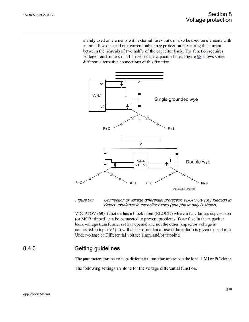
mainly used on elements with external fuses but can also be used on elements withinternal fuses instead of a current unbalance protection measuring the currentbetween the neutrals of two half’s of the capacitor bank. The function requiresvoltage transformers in all phases of the capacitor bank. Figure 98 shows somedifferent alternative connections of this function.
Vd>L1
Ph BPh C
V1
V2
Vd>A
Ph BPh C
V1 V2
Ph C Ph B
en06000390_ansi.vsd
Single grounded wye
Double wye
ANSI06000390 V1 EN
Figure 98: Connection of voltage differential protection VDCPTOV (60) function todetect unbalance in capacitor banks (one phase only is shown)
VDCPTOV (60) function has a block input (BLOCK) where a fuse failure supervision(or MCB tripped) can be connected to prevent problems if one fuse in the capacitorbank voltage transformer set has opened and not the other (capacitor voltage isconnected to input V2). It will also ensure that a fuse failure alarm is given instead of aUndervoltage or Differential voltage alarm and/or tripping.
8.4.3 Setting guidelinesThe parameters for the voltage differential function are set via the local HMI or PCM600.
The following settings are done for the voltage differential function.
1MRK 505 302-UUS - Section 8Voltage protection
235Application Manual

Operation: Off/On
GlobalBaseSel: Selects the global base value group used by the function to define(IBase), (VBase) and (SBase).
BlkDiffAtVLow: The setting is to block the function when the voltages in the phases arelow.
RFLx: Is the setting of the voltage ratio compensation factor where possible differencesbetween the voltages is compensated for. The differences can be due to differentvoltage transformer ratios, different voltage levels e.g. the voltage measurement insidethe capacitor bank can have a different voltage level but the difference can also e.g. beused by voltage drop in the secondary circuits. The setting is normally done at site byevaluating the differential voltage achieved as a service value for each phase. Thefactor is defined as V2 · RFLx and shall be equal to the V1 voltage. Each phase has itsown ratio factor.
VDTrip: The voltage differential level required for tripping is set with this parameter.For application on capacitor banks the setting will depend of the capacitor bank voltageand the number of elements per phase in series and parallel. Capacitor banks must betripped before excessive voltage occurs on the healthy capacitor elements. The settingvalues required are normally given by the capacitor bank supplier. For otherapplications it has to be decided case by case. For fuse supervision normally only thealarm level is used.
tTrip: The time delay for tripping is set by this parameter. Normally, the delay does notneed to be so short in capacitor bank applications as there is no fault requiring urgenttripping.
tReset: The time delay for reset of tripping level element is set by this parameter.Normally, it can be set to a short delay as faults are permanent when they occur.
For the advanced users following parameters are also available for setting. Defaultvalues are here expected to be acceptable.
V1Low: The setting of the undervoltage level for the first voltage input is decided bythis parameter. The proposed default setting is 70%.
V2Low: The setting of the undervoltage level for the second voltage input is decided bythis parameter. The proposed default setting is 70%.
tBlock: The time delay for blocking of the function at detected undervoltages is set bythis parameter.
VDAlarm: The voltage differential level required for alarm is set with this parameter.For application on capacitor banks the setting will depend of the capacitor bank voltage
Section 8 1MRK 505 302-UUS -Voltage protection
236Application Manual

and the number of elements per phase in series and parallel. Normally values requiredare given by capacitor bank supplier.
For fuse supervision normally only this alarm level is used and a suitable voltage levelis 3-5% if the ratio correction factor has been properly evaluated during commissioning.
For other applications it has to be decided case by case.
tAlarm: The time delay for alarm is set by this parameter. Normally, few seconds delaycan be used on capacitor banks alarm. For fuse failure supervision (SDDRFUF) thealarm delay can be set to zero.
8.5 Loss of voltage check LOVPTUV (27)
8.5.1 IdentificationFunction description IEC 61850
identificationIEC 60617identification
ANSI/IEEE C37.2device number
Loss of voltage check LOVPTUV - 27
8.5.2 ApplicationThe trip of the circuit breaker at a prolonged loss of voltage at all the three phases isnormally used in automatic restoration systems to facilitate the system restoration aftera major blackout. Loss of voltage check (LOVPTUV, 27) generates a TRIP signal onlyif the voltage in all the three phases is low for more than the set time. If the trip to thecircuit breaker is not required, LOVPTUV (27) is used for signallization only throughan output contact or through the event recording function.
8.5.3 Setting guidelinesLoss of voltage check (LOVPTUV, 27) is in principle independent of the protectionfunctions. It requires to be set to open the circuit breaker in order to allow a simplesystem restoration following a main voltage loss of a big part of the network and onlywhen the voltage is lost with breakers still closed.
All settings are in primary values or per unit. Set VBase to rated voltage of the systemor the voltage transformer primary rated voltage. Set operating level per phase VPG totypically 70% of rated VBase level. Set the time delay tTrip=5-20 seconds.
1MRK 505 302-UUS - Section 8Voltage protection
237Application Manual

8.5.3.1 Advanced users settings
For advanced users the following parameters need also to be set. Set the length of thetrip pulse to typical tPulse=0.15 sec. Set the blocking time tBlock to block Loss ofvoltage check (LOVPTUV, 27), if some but not all voltage are low, to typical 5.0seconds and set the time delay for enabling the function after restoration tRestore to 3 -40 seconds.
Section 8 1MRK 505 302-UUS -Voltage protection
238Application Manual
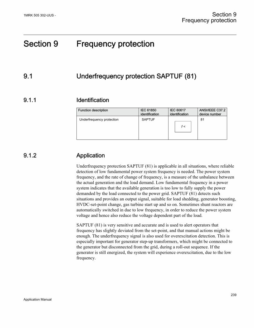
Section 9 Frequency protection
9.1 Underfrequency protection SAPTUF (81)
9.1.1 IdentificationFunction description IEC 61850
identificationIEC 60617identification
ANSI/IEEE C37.2device number
Underfrequency protection SAPTUF
f <
SYMBOL-P V1 EN
81
9.1.2 ApplicationUnderfrequency protection SAPTUF (81) is applicable in all situations, where reliabledetection of low fundamental power system frequency is needed. The power systemfrequency, and the rate of change of frequency, is a measure of the unbalance betweenthe actual generation and the load demand. Low fundamental frequency in a powersystem indicates that the available generation is too low to fully supply the powerdemanded by the load connected to the power grid. SAPTUF (81) detects suchsituations and provides an output signal, suitable for load shedding, generator boosting,HVDC-set-point change, gas turbine start up and so on. Sometimes shunt reactors areautomatically switched in due to low frequency, in order to reduce the power systemvoltage and hence also reduce the voltage dependent part of the load.
SAPTUF (81) is very sensitive and accurate and is used to alert operators thatfrequency has slightly deviated from the set-point, and that manual actions might beenough. The underfrequency signal is also used for overexcitation detection. This isespecially important for generator step-up transformers, which might be connected tothe generator but disconnected from the grid, during a roll-out sequence. If thegenerator is still energized, the system will experience overexcitation, due to the lowfrequency.
1MRK 505 302-UUS - Section 9Frequency protection
239Application Manual
9.1.3 Setting guidelinesAll the frequency and voltage magnitude conditions in the system where SAPTUF (81)performs its functions should be considered. The same also applies to the associatedequipment, its frequency and time characteristic.
There are especially two specific application areas for SAPTUF (81):
1. to protect equipment against damage due to low frequency, such as generators,transformers, and motors. Overexcitation is also related to low frequency
2. to protect a power system, or a part of a power system, against breakdown, byshedding load, in generation deficit situations.
The underfrequency PICKUP value is set in Hz. All voltage magnitude related settingsare made as a percentage of a settable base voltage, which normally is set to thenominal primary voltage level (phase-phase) of the power system or the high voltageequipment under consideration.
Some applications and related setting guidelines for the frequency level are given below:
Equipment protection, such as for motors and generatorsThe setting has to be well below the lowest occurring "normal" frequency and wellabove the lowest acceptable frequency for the equipment.
Power system protection, by load sheddingThe setting has to be below the lowest occurring "normal" frequency and well abovethe lowest acceptable frequency for power stations, or sensitive loads. The settinglevel, the number of levels and the distance between two levels (in time and/or infrequency) depends very much on the characteristics of the power system underconsideration. The size of the "largest loss of production" compared to "the size of thepower system" is a critical parameter. In large systems, the load shedding can be set ata fairly high frequency level, and the time delay is normally not critical. In smallersystems the frequency PICKUP level has to be set at a lower value, and the time delaymust be rather short.
The voltage related time delay is used for load shedding. The settings of SAPTUF (81)could be the same all over the power system. The load shedding is then performedfirstly in areas with low voltage magnitude, which normally are the most problematicareas, where the load shedding also is most efficient.
9.1.3.1 Equipment protection, such as for motors and generators
The setting has to be well below the lowest occurring "normal" frequency and wellabove the lowest acceptable frequency for the equipment.
Section 9 1MRK 505 302-UUS -Frequency protection
240Application Manual

9.1.3.2 Power system protection, by load shedding
The setting has to be well below the lowest occurring "normal" frequency and wellabove the lowest acceptable frequency for power stations, or sensitive loads. Thesetting level, the number of levels and the distance between two levels (in time and/orin frequency) depends very much on the characteristics of the power system underconsideration. The size of the "largest loss of production" compared to "the size of thepower system" is a critical parameter. In large systems, the load shedding can be set ata fairly high frequency level, and the time delay is normally not critical. In smallersystems the frequency pickup level has to be set at a lower value, and the time delaymust be rather short.
The voltage related time delay is used for load shedding. The settings of theunderfrequency function could be the same all over the power system. The loadshedding is then performed firstly in areas with low voltage magnitude, whichnormally are the most problematic areas, where the load shedding also is most efficient.
9.2 Overfrequency protection SAPTOF (81)
9.2.1 IdentificationFunction description IEC 61850
identificationIEC 60617identification
ANSI/IEEE C37.2device number
Overfrequency protection SAPTOF
f >
SYMBOL-O V1 EN
81
9.2.2 ApplicationOverfrequency protection function SAPTOF (81) is applicable in all situations, wherereliable detection of high fundamental power system frequency is needed. The powersystem frequency, and rate of change of frequency, is a measure of the unbalancebetween the actual generation and the load demand. High fundamental frequency in apower system indicates that the available generation is too large compared to the powerdemanded by the load connected to the power grid. SAPTOF (81) detects suchsituations and provides an output signal, suitable for generator shedding, HVDC-set-point change and so on. SAPTOF (81) is very sensitive and accurate and can also beused to alert operators that frequency has slightly deviated from the set-point, and thatmanual actions might be enough.
1MRK 505 302-UUS - Section 9Frequency protection
241Application Manual
9.2.3 Setting guidelinesAll the frequency and voltage magnitude conditions in the system where SAPTOF (81)performs its functions must be considered. The same also applies to the associatedequipment, its frequency and time characteristic.
There are especially two application areas for SAPTOF (81):
1. to protect equipment against damage due to high frequency, such as generators,and motors
2. to protect a power system, or a part of a power system, against breakdown, byshedding generation, in over production situations.
The overfrequency PICKUP value is set in Hz. All voltage magnitude related settingsare made as a percentage of a settable base voltage, which normally is set to thenominal voltage level (phase-to-phase) of the power system or the high voltageequipment under consideration.
Some applications and related setting guidelines for the frequency level are given below:
Equipment protection, such as for motors and generatorsThe setting has to be well above the highest occurring "normal" frequency and wellbelow the highest acceptable frequency for the equipment.
Power system protection, by generator sheddingThe setting must be above the highest occurring "normal" frequency and below thehighest acceptable frequency for power stations, or sensitive loads. The setting level,the number of levels and the distance between two levels (in time and/or in frequency)depend very much on the characteristics of the power system under consideration. Thesize of the "largest loss of load" compared to "the size of the power system" is a criticalparameter. In large systems, the generator shedding can be set at a fairly low frequencylevel, and the time delay is normally not critical. In smaller systems the frequencyPICKUP level has to be set at a higher value, and the time delay must be rather short.
9.2.3.1 Equipment protection, such as for motors and generators
The setting has to be well above the highest occurring "normal" frequency and wellbelow the highest acceptable frequency for the equipment.
9.2.3.2 Power system protection, by generator shedding
The setting level, the number of levels and the distance between two levels (in time and/or in frequency) depend very much on the characteristics of the power system underconsideration. The size of the "largest loss of load" compared to "the size of the power
Section 9 1MRK 505 302-UUS -Frequency protection
242Application Manual

system" is a critical parameter. In large systems, the generator shedding can be set at afairly low frequency level, and the time delay is normally not critical. In smallersystems the frequency pickup level has to be set at a higher value, and the time delaymust be rather short.
9.3 Rate-of-change frequency protection SAPFRC (81)
9.3.1 IdentificationFunction description IEC 61850
identificationIEC 60617identification
ANSI/IEEE C37.2device number
Rate-of-change frequency protection SAPFRC
df/dt ><
SYMBOL-N V1 EN
81
9.3.2 ApplicationRate-of-change frequency protection (SAPFRC, 81), is applicable in all situations,where reliable detection of change of the fundamental power system voltage frequencyis needed. SAPFRC (81) can be used both for increasing frequency and for decreasingfrequency. SAPFRC (81) provides an output signal, suitable for load shedding orgenerator shedding, generator boosting, HVDC-set-point change, gas turbine start upand so on. Very often SAPFRC (81) is used in combination with a low frequencysignal, especially in smaller power systems, where loss of a fairly large generator willrequire quick remedial actions to secure the power system integrity. In such situationsload shedding actions are required at a rather high frequency level, but in combinationwith a large negative rate-of-change of frequency the underfrequency protection can beused at a rather high setting.
9.3.3 Setting guidelinesThe parameters for Rate-of-change frequency protection SAPFRC (81) are set via thelocal HMI or PCM600.
All the frequency and voltage magnitude conditions in the system where SAPFRC (81)performs its functions should be considered. The same also applies to the associatedequipment, its frequency and time characteristic.
There are especially two application areas for SAPFRC (81):
1MRK 505 302-UUS - Section 9Frequency protection
243Application Manual

1. to protect equipment against damage due to high or too low frequency, such asgenerators, transformers, and motors
2. to protect a power system, or a part of a power system, against breakdown byshedding load or generation, in situations where load and generation are not inbalance.
SAPFRC (81) is normally used together with an overfrequency or underfrequencyfunction, in small power systems, where a single event can cause a large imbalancebetween load and generation. In such situations load or generation shedding has to takeplace very quickly, and there might not be enough time to wait until the frequencysignal has reached an abnormal value. Actions are therefore taken at a frequency levelcloser to the primary nominal level, if the rate-of-change frequency is large (withrespect to sign).
SAPFRC (81)PICKUP value is set in Hz/s. All voltage magnitude related settings aremade as a percentage of a settable base voltage, which normally is set to the primarynominal voltage level (phase-phase) of the power system or the high voltage equipmentunder consideration.
SAPFRC (81) is not instantaneous, since the function needs some time to supply astable value. It is recommended to have a time delay long enough to take care of signalnoise. However, the time, rate-of-change frequency and frequency steps betweendifferent actions might be critical, and sometimes a rather short operation time isrequired, for example, down to 70 ms.
Smaller industrial systems might experience rate-of-change frequency as large as 5 Hz/s, due to a single event. Even large power systems may form small islands with a largeimbalance between load and generation, when severe faults (or combinations of faults)are cleared - up to 3 Hz/s has been experienced when a small island was isolated froma large system. For more "normal" severe disturbances in large power systems, rate-of-change of frequency is much less, most often just a fraction of 1.0 Hz/s.
Section 9 1MRK 505 302-UUS -Frequency protection
244Application Manual

Section 10 Multipurpose protection
10.1 General current and voltage protection CVGAPC
10.1.1 IdentificationFunction description IEC 61850
identificationIEC 60617identification
ANSI/IEEE C37.2device number
General current and voltage protection CVGAPC 2(I>/U<) -
10.1.2 ApplicationA breakdown of the insulation between phase conductors or a phase conductor andground results in a short circuit or a ground fault respectively. Such faults can result inlarge fault currents and may cause severe damage to the power system primaryequipment. Depending on the magnitude and type of the fault different overcurrentprotections, based on measurement of phase, ground or sequence current componentscan be used to clear these faults. Additionally it is sometimes required that theseovercurrent protections shall be directional and/or voltage controlled/restrained.
The over/under voltage protection is applied on power system elements, such asgenerators, transformers, motors and power lines in order to detect abnormal voltageconditions. Depending on the type of voltage deviation and type of power systemabnormal condition different over/under voltage protections based on measurement ofphase-to-ground, phase-to-phase, residual- or sequence- voltage components can beused to detect and operate for such incident.
The IED can be provided with multiple General current and voltage protection(CVGAPC) protection modules. The function is always connected to three-phasecurrent and three-phase voltage input in the configuration tool, but it will alwaysmeasure only one current and one voltage quantity selected by the end user in thesetting tool.
Each CVGAPC function module has got four independent protection elements builtinto it.
1. Two overcurrent steps with the following built-in features:
1MRK 505 302-UUS - Section 10Multipurpose protection
245Application Manual

• Definite time delay or Inverse Time Overcurrent TOC/IDMT delay for bothsteps
• Second harmonic supervision is available in order to only allow operation ofthe overcurrent stage(s) if the content of the second harmonic in themeasured current is lower than pre-set level
• Directional supervision is available in order to only allow operation of theovercurrent stage(s) if the fault location is in the pre-set direction (Forwardor Reverse). Its behavior during low-level polarizing voltage is settable (Non-Directional,Block,Memory)
• Voltage restrained/controlled feature is available in order to modify the pick-up level of the overcurrent stage(s) in proportion to the magnitude of themeasured voltage
• Current restrained feature is available in order to only allow operation of theovercurrent stage(s) if the measured current quantity is bigger than the setpercentage of the current restrain quantity.
2. Two undercurrent steps with the following built-in features:• Definite time delay for both steps
3. Two overvoltage steps with the following built-in features• Definite time delay or Inverse Time Overcurrent TOC/IDMT delay for both
steps4. Two undervoltage steps with the following built-in features
• Definite time delay or Inverse Time Overcurrent TOC/IDMT delay for bothsteps
All these four protection elements within one general protection function worksindependently from each other and they can be individually enabled or disabled.However it shall be once more noted that all these four protection elements measureone selected current quantity and one selected voltage quantity (see table 30 andtable 31). It is possible to simultaneously use all four-protection elements and theirindividual stages. Sometimes in order to obtain desired application functionality it isnecessary to provide interaction between two or more protection elements/stageswithin one CVGAPC function by appropriate IED configuration (for example, deadmachine protection for generators).
10.1.2.1 Current and voltage selection for CVGAPC function
CVGAPC function is always connected to three-phase current and three-phase voltageinput in the configuration tool, but it will always measure only the single current andthe single voltage quantity selected by the end user in the setting tool (selected currentquantity and selected voltage quantity).
Section 10 1MRK 505 302-UUS -Multipurpose protection
246Application Manual

The user can select, by a setting parameter CurrentInput, to measure one of thefollowing current quantities shown in table 30.
Table 30: Available selection for current quantity within CVGAPC function
Set value for parameter"CurrentInput”
Comment
1 PhaseA CVGAPC function will measure the phase A current phasor
2 PhaseB CVGAPC function will measure the phase B current phasor
3 PhaseC CVGAPC function will measure the phase C current phasor
4 PosSeq CVGAPC function will measure internally calculated positivesequence current phasor
5 NegSeq CVGAPC function will measure internally calculated negativesequence current phasor
6 3 · ZeroSeq CVGAPC function will measure internally calculated zero sequencecurrent phasor multiplied by factor 3
7 MaxPh CVGAPC function will measure current phasor of the phase withmaximum magnitude
8 MinPh CVGAPC function will measure current phasor of the phase withminimum magnitude
9 UnbalancePh CVGAPC function will measure magnitude of unbalance current,which is internally calculated as the algebraic magnitude differencebetween the current phasor of the phase with maximum magnitudeand current phasor of the phase with minimum magnitude. Phaseangle will be set to 0° all the time
10 PhaseA-PhaseB CVGAPC function will measure the current phasor internallycalculated as the vector difference between the phase A currentphasor and phase B current phasor (VA-VB)
11 PhaseB-PhaseC CVGAPC function will measure the current phasor internallycalculated as the vector difference between the phase B currentphasor and phase C current phasor (VB-VC)
12 PhaseC-PhaseA CVGAPC function will measure the current phasor internallycalculated as the vector difference between the phase C currentphasor and phase A current phasor ( VC-VA)
13 MaxPh-Ph CVGAPC function will measure ph-ph current phasor with themaximum magnitude
14 MinPh-Ph CVGAPC function will measure ph-ph current phasor with theminimum magnitude
15 UnbalancePh-Ph CVGAPC function will measure magnitude of unbalance current,which is internally calculated as the algebraic magnitude differencebetween the ph-ph current phasor with maximum magnitude and ph-ph current phasor with minimum magnitude. Phase angle will beset to 0° all the time
The user can select, by a setting parameter VoltageInput, to measure one of thefollowing voltage quantities shown in table 31.
1MRK 505 302-UUS - Section 10Multipurpose protection
247Application Manual

Table 31: Available selection for voltage quantity within CVGAPC function
Set value for parameter"VoltageInput"
Comment
1 PhaseA CVGAPC function will measure the phase A voltage phasor
2 PhaseB CVGAPC function will measure the phase B voltage phasor
3 PhaseC CVGAPC function will measure the phase C voltage phasor
4 PosSeq CVGAPC function will measure internally calculated positivesequence voltage phasor
5 -NegSeq CVGAPC function will measure internally calculated negativesequence voltage phasor. This voltage phasor will be intentionallyrotated for 180° in order to enable easier settings for the directionalfeature when used.
6 -3*ZeroSeq CVGAPC function will measure internally calculated zero sequencevoltage phasor multiplied by factor 3. This voltage phasor will beintentionally rotated for 180° in order to enable easier settings forthe directional feature when used.
7 MaxPh CVGAPC function will measure voltage phasor of the phase withmaximum magnitude
8 MinPh CVGAPC function will measure voltage phasor of the phase withminimum magnitude
9 UnbalancePh CVGAPC function will measure magnitude of unbalance voltage,which is internally calculated as the algebraic magnitude differencebetween the voltage phasor of the phase with maximum magnitudeand voltage phasor of the phase with minimum magnitude. Phaseangle will be set to 0° all the time
10 PhaseA-PhaseB CVGAPC function will measure the voltage phasor internallycalculated as the vector difference between the phase A voltagephasor and phase B voltage phasor (VA-VB)
11 PhaseB-PhaseC CVGAPC function will measure the voltage phasor internallycalculated as the vector difference between the phase B voltagephasor and phase C voltage phasor (VB-VC)
12 PhaseC-PhaseC CVGAPC function will measure the voltage phasor internallycalculated as the vector difference between the phase C voltagephasor and phase A voltage phasor (VC-VA)
13 MaxPh-Ph CVGAPC function will measure ph-ph voltage phasor with themaximum magnitude
14 MinPh-Ph CVGAPC function will measure ph-ph voltage phasor with theminimum magnitude
15 UnbalancePh-Ph CVGAPC function will measure magnitude of unbalance voltage,which is internally calculated as the algebraic magnitude differencebetween the ph-ph voltage phasor with maximum magnitude and ph-ph voltage phasor with minimum magnitude. Phase angle will beset to 0° all the time
It is important to notice that the voltage selection from table 31 is always applicableregardless the actual external VT connections. The three-phase VT inputs can beconnected to IED as either three phase-to-groundvoltages VA, VB and VC or three phase-
Section 10 1MRK 505 302-UUS -Multipurpose protection
248Application Manual
to-phase voltages VAB, VBC and VCA. This information about actual VT connectionis entered as a setting parameter for the pre-processing block, which will then takeautomatically care about it.
10.1.2.2 Base quantities for CVGAPC function
The parameter settings for the base quantities, which represent the base (100%) forpickup levels of all measuring stages shall be entered as setting parameters for everyCVGAPC function.
Base current shall be entered as:
1. rated phase current of the protected object in primary amperes, when the measuredCurrent Quantity is selected from 1 to 9, as shown in table 30.
2. rated phase current of the protected object in primary amperes multiplied by √3(1.732 x Iphase), when the measured Current Quantity is selected from 10 to 15, asshown in table 30.
Base voltage shall be entered as:
1. rated phase-to-ground voltage of the protected object in primary kV, when themeasured Voltage Quantity is selected from 1 to 9, as shown in table 31.
2. rated phase-to-phase voltage of the protected object in primary kV, when themeasured Voltage Quantity is selected from 10 to 15, as shown in table 31.
10.1.2.3 Application possibilities
Due to its flexibility the general current and voltage protection (CVGAPC) functioncan be used, with appropriate settings and configuration in many different applications.Some of possible examples are given below:
1. Transformer and line applications:• Underimpedance protection (circular, non-directional characteristic) (21)• Underimpedance protection (circular mho characteristic) (21)• Voltage Controlled/Restrained Overcurrent protection (51C, 51V)• Phase or Negative/Positive/Zero Sequence (Non-Directional or Directional)
Overcurrent protection (50, 51, 46, 67, 67N, 67Q)• Phase or phase-to-phase or Negative/Positive/Zero Sequence over/under
voltage protection (27, 59, 47)• Special thermal overload protection (49)• Open Phase protection• Unbalance protection
2. Generator protection
1MRK 505 302-UUS - Section 10Multipurpose protection
249Application Manual

• 80-95% Stator earth fault protection (measured or calculated 3Vo) (59GN)• Rotor earth fault protection (with external COMBIFLEX RXTTE4 injection
unit) (64F)• Underimpedance protection (21)• Voltage Controlled/Restrained Overcurrent protection (51C, 51V)• Turn-to-Turn & Differential Backup protection (directional Negative
Sequence. Overcurrent protection connected to generator HV terminal CTslooking into generator) (67Q)
• Stator Overload protection (49S)• Rotor Overload protection (49R)• Loss of Excitation protection (directional pos. seq. OC protection) (40)• Reverse power/Low forward power protection (directional pos. seq. OC
protection, 2% sensitivity) (32)• Dead-Machine/Inadvertent-Energizing protection (51/27)• Breaker head flashover protection• Improper synchronizing detection• Sensitive negative sequence generator over current protection and alarm (46)• Phase or phase-to-phase or Negative/Positive/Zero Sequence over/under
voltage protection (27x, 59x, 47)• Generator out-of-step detection (based on directional pos. seq. OC) (78)• Inadvertent generator energizing
10.1.2.4 Inadvertent generator energization
When the generator is taken out of service, and stand-still, there is a risk that thegenerator circuit breaker is closed by mistake.
Three-phase energizing of a generator, which is at standstill or on turning gear, causesit to behave and accelerate similarly to an induction motor. The machine, at this point,essentially represents the subtransient reactance to the system and it can be expected todraw from one to four per unit current, depending on the equivalent system impedance.Machine terminal voltage can range from 20% to 70% of rated voltage, again,depending on the system equivalent impedance (including the block transformer).Higher quantities of machine current and voltage (3 to 4 per unit current and 50% to70% rated voltage) can be expected if the generator is connected to a strong system.Lower current and voltage values (1 to 2 per unit current and 20% to 40% ratedvoltage) are representative of weaker systems.
Since a generator behaves similarly to an induction motor, high currents will developin the rotor during the period it is accelerating. Although the rotor may be thermallydamaged from excessive high currents, the time to damage will be on the order of afew seconds. Of more critical concern, however, is the bearing, which can be damagedin a fraction of a second due to low oil pressure. Therefore, it is essential that highspeed tripping is provided. This tripping should be almost instantaneous (< 100 ms).
Section 10 1MRK 505 302-UUS -Multipurpose protection
250Application Manual

There is a risk that the current into the generator at inadvertent energization will belimited so that the “normal” overcurrent or underimpedance protection will not detectthe dangerous situation. The delay of these protection functions might be too long. Thereverse power protection might detect the situation but the operation time of thisprotection is normally too long.
For big and important machines, fast protection against inadvertent energizing should,therefore, be included in the protective scheme.
The protection against inadvertent energization can be made by a combination ofundervoltage, overvoltage and overcurrent protection functions. The undervoltagefunction will, with a delay for example 10 s, detect the situation when the generator isnot connected to the grid (standstill) and activate the overcurrent function. Theovervoltage function will detect the situation when the generator is taken into operationand will disable the overcurrent function. The overcurrent function will have a pick-upvalue about 50% of the rated current of the generator. The trip delay will be about 50 ms.
10.1.3 Setting guidelines
When inverse time overcurrent characteristic is selected, the operatetime of the stage will be the sum of the inverse time delay and the setdefinite time delay. Thus, if only the inverse time delay is required, it isof utmost importance to set the definite time delay for that stage to zero.
The parameters for the general current and voltage protection function (CVGAPC) areset via the local HMI or Protection and Control Manager (PCM600).
The overcurrent steps has a IMinx (x=1 or 2 depending on step) settingto set the minimumpickup current. Set IMinx below PickupCurr_OCxfor every step to achieve ANSI reset characteristic according tostandard. If IMinx is set above PickupCurr_OCx for any step the ANSIreset works as if current is zero when current drops below IMinx.
10.1.3.1 Directional negative sequence overcurrent protection
Directional negative sequence overcurrent protection is typically used as sensitiveground-fault protection of power lines where incorrect zero sequence polarization mayresult from mutual induction between two or more parallel lines. Additionally, it can beused in applications on underground cables where zero-sequence impedance dependson the fault current return paths, but the cable negative-sequence impedance ispractically constant. It shall be noted that directional negative sequence OC elementoffers protection against all unbalance faults (phase-to-phase faults as well). Care shall
1MRK 505 302-UUS - Section 10Multipurpose protection
251Application Manual
be taken that the minimum pickup of such protection function shall be set abovenatural system unbalance level.
An example will be given, how sensitive-ground-fault protection for power lines canbe achieved by using negative-sequence directional overcurrent protection elementswithin a CVGAPC function.
This functionality can be achieved by using one CVGAPC function. The followingshall be done to ensure proper operation of the function:
1. Connect three-phase power line currents and three-phase power line voltages toone CVGAPC instance (for example, GF04)
2. Set CurrentInput to NegSeq (please note that CVGAPC function measures I2current and NOT 3I2 current; this is essential for proper OC pickup level setting)
3. Set VoltageInput to -NegSeq (please note that the negative sequence voltagephasor is intentionally inverted in order to simplify directionality
4. Set base current IBase value equal to the rated primary current of power line CTs5. Set base voltage UBase value equal to the rated power line phase-to-phase voltage
in kV6. Set RCADir to value +65 degrees (NegSeq current typically lags the inverted
NegSeq voltage for this angle during the fault)7. Set ROADir to value 90 degree8. Set LowVolt_VM to value 2% (NegSeq voltage level above which the directional
element will be enabled)9. Enable one overcurrent stage (for example, OC1)10. By parameter CurveType_OC1 select appropriate TOC/IDMT or definite time
delayed curve in accordance with your network protection philosophy11. Set PickupCurr_OC1 to value between 3-10% (typical values)12. Set tDef_OC1 or parameter “TD” when TOC/IDMT curves are used to insure
proper time coordination with other ground-fault protections installed in thevicinity of this power line
13. Set DirMode_OC1 to Forward14. Set DirPrinc_OC1 to IcosPhi&U15. Set ActLowVolt1_VM to Block
• In order to insure proper restraining of this element for CT saturations duringthree-phase faults it is possible to use current restraint feature and enable thiselement to operate only when NegSeq current is bigger than a certainpercentage (10% is typical value) of measured PosSeq current in the powerline. To do this the following settings within the same function shall be done:
16. Set EnRestrainCurr to On17. Set RestrCurrInput to PosSeq18. Set RestrCurrCoeff to value 0.1
Section 10 1MRK 505 302-UUS -Multipurpose protection
252Application Manual

If required, this CVGAPC function can be used in directional comparison protectionscheme for the power line protection if communication channels to the remote end ofthis power line are available. In that case typically two NegSeq overcurrent steps arerequired. One for forward and one for reverse direction. As explained before the OC1stage can be used to detect faults in forward direction. The built-in OC2 stage can beused to detect faults in reverse direction.
However the following shall be noted for such application:
• the set values for RCADir and ROADir settings will be as well applicable for OC2stage
• setting DirMode_OC2 shall be set to Reverse• setting parameter PickupCurr_OC2 shall be made more sensitive than pickup
value of forward OC1 element (that is, typically 60% of OC1 set pickup level) inorder to insure proper operation of the directional comparison scheme duringcurrent reversal situations
• pickup signals from OC1 and OC2 elements shall be used to send forward andreverse signals to the remote end of the power line
• the available scheme communications function block within IED shall be usedbetween multipurpose protection function and the communication equipment inorder to insure proper conditioning of the above two pickup signals
Furthermore the other built-in UC, OV and UV protection elements can be used forother protection and alarming purposes.
10.1.3.2 Negative sequence overcurrent protection
Example will be given how to use one CVGAPC function to provide negativesequence inverse time overcurrent protection for a generator with capability constant of20s, and maximum continuous negative sequence rating of 7% of the generator ratedcurrent.
The capability curve for a generator negative sequence overcurrent protection, oftenused world-wide, is defined by the ANSI standard in accordance with the followingformula:
1MRK 505 302-UUS - Section 10Multipurpose protection
253Application Manual

op 2
NS
r
TDt
II
=æ öç ÷è ø
EQUATION1740-ANSI V1 EN (Equation 75)
where:
top is the operating time in seconds of the negative sequence overcurrent IED
TD is the generator capability constant in seconds
INS is the measured negative sequence current
Ir is the generator rated current
By defining parameter x equal to maximum continuous negative sequence rating of thegenerator in accordance with the following formula
7% 0.07= =x puEQUATION1756-ANSI V1 EN (Equation 76)
Equation 75 can be re-written in the following way without changing the value for theoperate time of the negative sequence inverse overcurrent IED:
op 2
NS
r
2TDt
Ix I
1x×
=
×
æ öç ÷è ø
EQUATION1741-ANSI V1 EN (Equation 77)
In order to achieve such protection functionality with one CVGAPC functions thefollowing must be done:
1. Connect three-phase generator currents to one CVGAPC instance (for example,GF01)
2. Set parameter CurrentInput to value NegSeq3. Set base current value to the rated generator current in primary amperes4. Enable one overcurrent step (for example, OC1)5. Select parameter CurveType_OC1 to value Programmable
Section 10 1MRK 505 302-UUS -Multipurpose protection
254Application Manual

op Pt TDA B
M C= ×æ ö+ç ÷-è ø
EQUATION1742-ANSI V1 EN (Equation 78)
where:
top is the operating time in seconds of the Inverse Time Overcurrent TOC/IDMT algorithm
TD is time multiplier (parameter setting)
M is ratio between measured current magnitude and set pickup current level
A, B, C and P are user settable coefficients which determine the curve used for Inverse Time OvercurrentTOC/IDMT calculation
When the equation 75 is compared with the equation 77 for the inverse timecharacteristic of the OC1 it is obvious that if the following rules are followed:
1. set TD equal to the generator negative sequence capability value2. set A_OC1 equal to the value 1/x23. set B_OC1 = 0.0, C_OC1=0.0 and P_OC1=2.04. set PickupCurr_OC1 equal to the value x
then the OC1 step of the CVGAPC function can be used for generator negativesequence inverse overcurrent protection.
For this particular example the following settings shall be entered to insure properfunction operation:
1. select negative sequence current as measuring quantity for this CVGAPC function2. make sure that the base current value for the CVGAPC function is equal to the
generator rated current3. set TD_OC1 = 204. set A_OC1= 1/0.072 = 204.08165. set B_OC1 = 0.0, C_OC1 = 0.0 and P_OC1 = 2.06. set PickupCurr_OC1 = 7%
Proper timing of the CVGAPC function made in this way can easily be verified bysecondary injection. All other settings can be left at the default values. If requireddelayed time reset for OC1 step can be set in order to ensure proper function operationin case of repetitive unbalance conditions.
Furthermore the other built-in protection elements can be used for other protection andalarming purposes (for example, use OC2 for negative sequence overcurrent alarm andOV1 for negative sequence overvoltage alarm).
1MRK 505 302-UUS - Section 10Multipurpose protection
255Application Manual
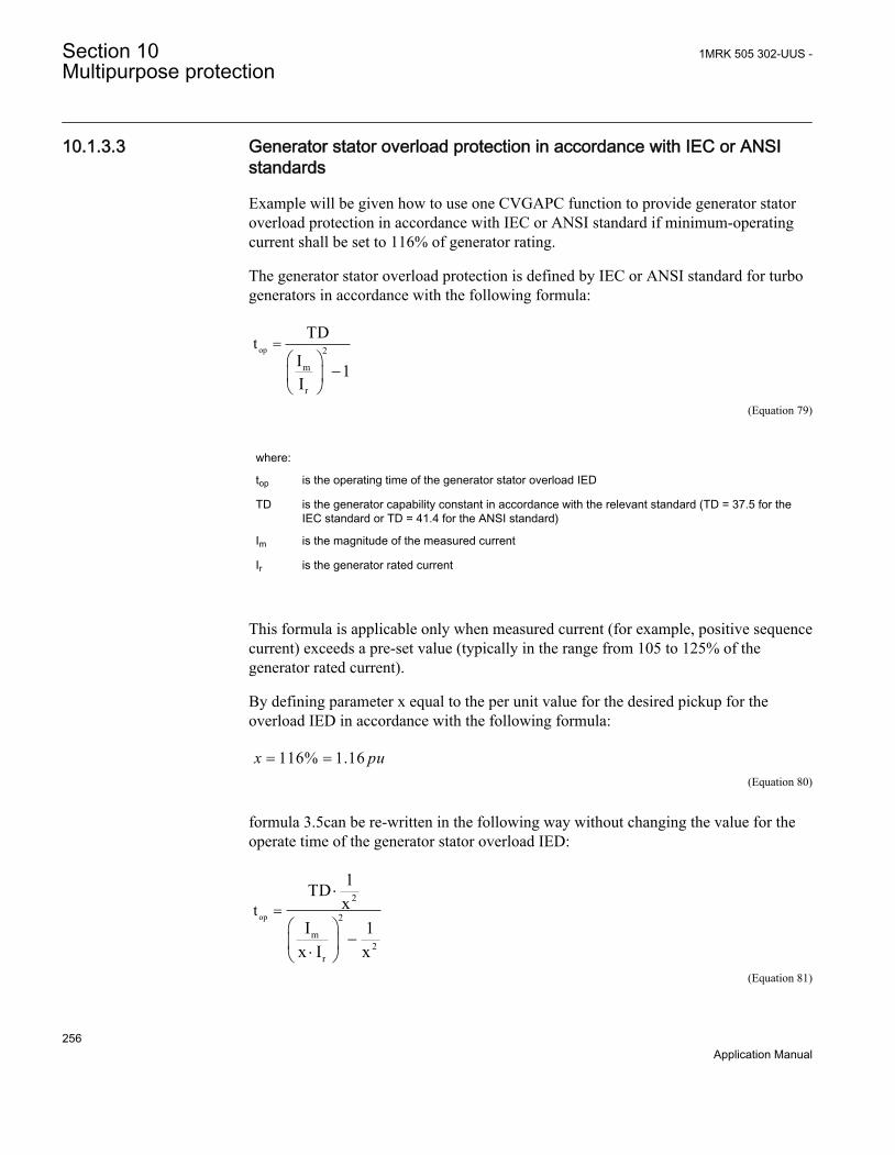
10.1.3.3 Generator stator overload protection in accordance with IEC or ANSIstandards
Example will be given how to use one CVGAPC function to provide generator statoroverload protection in accordance with IEC or ANSI standard if minimum-operatingcurrent shall be set to 116% of generator rating.
The generator stator overload protection is defined by IEC or ANSI standard for turbogenerators in accordance with the following formula:
op 2
m
r
tTD
I 1I
=æ ö
-ç ÷è ø
EQUATION1743-ANSI V1 EN (Equation 79)
where:
top is the operating time of the generator stator overload IED
TD is the generator capability constant in accordance with the relevant standard (TD = 37.5 for theIEC standard or TD = 41.4 for the ANSI standard)
Im is the magnitude of the measured current
Ir is the generator rated current
This formula is applicable only when measured current (for example, positive sequencecurrent) exceeds a pre-set value (typically in the range from 105 to 125% of thegenerator rated current).
By defining parameter x equal to the per unit value for the desired pickup for theoverload IED in accordance with the following formula:
116% 1.16= =x puEQUATION1755-ANSI V1 EN (Equation 80)
formula 3.5can be re-written in the following way without changing the value for theoperate time of the generator stator overload IED:
op
2
2
m2
r
t
1TDx
I 1x I x
=×
æ ö-ç ÷×è ø
EQUATION1744-ANSI V1 EN (Equation 81)
Section 10 1MRK 505 302-UUS -Multipurpose protection
256Application Manual

In order to achieve such protection functionality with one CVGAPC functions thefollowing must be done:
1. Connect three-phase generator currents to one CVGAPC instance (for example,GF01)
2. Set parameter CurrentInput to value PosSeq3. Set base current value to the rated generator current in primary amperes4. Enable one overcurrent step (for example OC1)5. Select parameter CurveType_OC1 to value Programmable
op Pt TDA B
M C= ×æ ö+ç ÷-è ø
EQUATION1745-ANSI V1 EN (Equation 82)
where:
top is the operating time in seconds of the Inverse Time Overcurrent TOC/IDMT algorithm
TD is time multiplier (parameter setting)
M is ratio between measured current magnitude and set pickup current level
A, B, C and P are user settable coefficients which determine the curve used for Inverse Time OvercurrentTOC/IDMT calculation
When the equation 81 is compared with the equation 82 for the inverse timecharacteristic of the OC1 step in it is obvious that if the following rules are followed:
1. set TD equal to the IEC or ANSI standard generator capability value2. set parameter A_OC1 equal to the value 1/x23. set parameter C_OC1 equal to the value 1/x24. set parameters B_OC1 = 0.0 and P_OC1=2.05. set PickupCurr_OC1 equal to the value x
then the OC1 step of the CVGAPC function can be used for generator negativesequence inverse overcurrent protection.
1. select positive sequence current as measuring quantity for this CVGAPC function2. make sure that the base current value for CVGAPC function is equal to the
generator rated current3. set TD = 37.5 for the IEC standard or TD = 41.4 for the ANSI standard4. set A_OC1= 1/1.162 = 0.74325. set C_OC1= 1/1.162 = 0.74326. set B_OC1 = 0.0 and P_OC1 = 2.07. set PickupCurr_OC1 = 116%
1MRK 505 302-UUS - Section 10Multipurpose protection
257Application Manual

Proper timing of CVGAPC function made in this way can easily be verified bysecondary injection. All other settings can be left at the default values. If requireddelayed time reset for OC1 step can be set in order to insure proper function operationin case of repetitive overload conditions.
Furthermore the other built-in protection elements can be used for other protection andalarming purposes.
In the similar way rotor overload protection in accordance with ANSI standard can beachieved.
10.1.3.4 Open phase protection for transformer, lines or generators and circuitbreaker head flashover protection for generators
Example will be given how to use one CVGAPC function to provide open phaseprotection. This can be achieved by using one CVGAPC function by comparing theunbalance current with a pre-set level. In order to make such a function more secure itis possible to restrain it by requiring that at the same time the measured unbalancecurrent must be bigger than 97% of the maximum phase current. By doing this it willbe insured that function can only pickup if one of the phases is open circuited. Such anarrangement is easy to obtain in CVGAPC function by enabling the current restraintfeature. The following shall be done in order to insure proper operation of the function:
1. Connect three-phase currents from the protected object to one CVGAPC instance(for example, GF03)
2. Set CurrentInput to value UnbalancePh3. Set EnRestrainCurr to On4. Set RestrCurrInput to MaxPh5. Set RestrCurrCoeff to value 0.976. Set base current value to the rated current of the protected object in primary amperes7. Enable one overcurrent step (for example, OC1)8. Select parameter CurveType_OC1 to value IEC Def. Time9. Set parameter PickupCurr_OC1 to value 5%10. Set parameter tDef_OC1 to desired time delay (for example, 2.0s)
Proper operation of CVGAPC function made in this way can easily be verified bysecondary injection. All other settings can be left at the default values. However it shallbe noted that set values for restrain current and its coefficient will as well be applicablefor OC2 step as soon as it is enabled.
Furthermore the other built-in protection elements can be used for other protection andalarming purposes. For example, in case of generator application by enabling OC2 stepwith set pickup to 200% and time delay to 0.1s simple but effective protection againstcircuit breaker head flashover protection is achieved.
Section 10 1MRK 505 302-UUS -Multipurpose protection
258Application Manual
10.1.3.5 Voltage restrained overcurrent protection for generator and step-uptransformer
Example will be given how to use one CVGAPC function to provide voltage restrainedovercurrent protection for a generator. Let us assume that the time coordination studygives the following required settings:
• Inverse Time Over Current TOC/IDMT curve: ANSI very inverse• Pickup current of 185% of generator rated current at rated generator voltage• Pickup current 25% of the original pickup current value for generator voltages
below 25% of rated voltage
This functionality can be achieved by using one CVGAPC function. The followingshall be done in order to insure proper operation of the function:
1. Connect three-phase generator currents and voltages to one CVGAPC instance(for example, GF05)
2. Set CurrentInput to value MaxPh3. Set VoltageInput to value MinPh-Ph (it is assumed that minimum phase-to-phase
voltage shall be used for restraining. Alternatively, positive sequence voltage canbe used for restraining by selecting PosSeq for this setting parameter)
4. Set base current value to the rated generator current primary amperes5. Set base voltage value to the rated generator phase-to-phase voltage in kV6. Enable one overcurrent step (for example, OC1)7. Select CurveType_OC1 to value ANSI Very inv8. If required set minimum operating time for this curve by using parameter
tMin_OC1 (default value 0.05s)9. Set PickupCurr_OC1 to value 185%10. Set VCntrlMode_OC1 to On11. Set VDepMode_OC1 to Slope12. Set VDepFact_OC1 to value 0.2513. Set VHighLimit_OC1 to value 100%14. Set VLowLimit_OC1 to value 25%
Proper operation of the CVGAPC function made in this way can easily be verified bysecondary injection. All other settings can be left at the default values. Furthermore theother built-in protection elements can be used for other protection and alarming purposes.
10.1.3.6 Loss of excitation protection for a generator
Example will be given how by using positive sequence directional overcurrentprotection element within a CVGAPC function, loss of excitation protection for agenerator can be achieved. Let us assume that from rated generator data the followingvalues are calculated:
1MRK 505 302-UUS - Section 10Multipurpose protection
259Application Manual

• Maximum generator capability to contentiously absorb reactive power at zeroactive loading 38% of the generator MVA rating
• Generator pull-out angle 84 degrees
This functionality can be achieved by using one CVGAPC function. The followingshall be done in order to insure proper operation of the function:
1. Connect three-phase generator currents and three-phase generator voltages to oneCVGAPC instance (for example, GF02)
2. Set parameter CurrentInput to PosSeq3. Set parameter VoltageInput to PosSeq4. Set base current value to the rated generator current primary amperes5. Set base voltage value to the rated generator phase-to-phase voltage in kV6. Set parameter RCADir to value -84 degree (that is, current lead voltage for this angle)7. Set parameter ROADir to value 90 degree8. Set parameter LowVolt_VM to value 5%9. Enable one overcurrent step (for example, OC1)10. Select parameter CurveType_OC1 to value IEC Def. Time11. Set parameter PickupCurr_OC1 to value 38%12. Set parameter tDef_OC1 to value 2.0s (typical setting)13. Set parameter DirMode_OC1 to Forward14. Set parameter DirPrinc_OC1 to IcosPhi&V15. Set parameter ActLowVolt1_VM to Block
Proper operation of the CVGAPC function made in this way can easily be verified bysecondary injection. All other settings can be left at the default values. However it shallbe noted that set values for RCA & ROA angles will be applicable for OC2 step ifdirectional feature is enabled for this step as well. Figure 99 shows overall protectioncharacteristic
Furthermore the other build-in protection elements can be used for other protection andalarming purposes.
Section 10 1MRK 505 302-UUS -Multipurpose protection
260Application Manual

0.2 0.4 0.6
-0.2
0.6
0.8
0.8 1
DILowSet
B
A
C
0.4
0.2
01.2 1.4
-0.4
-0.6
-0.8
-rca
Operating Region
Q [pu]
P [pu]
rca
VPS
IPSILowSet
Operating region
en05000535_ansi.vsdANSI05000535 V1 EN
Figure 99: Loss of excitation
1MRK 505 302-UUS - Section 10Multipurpose protection
261Application Manual

262
Section 11 Secondary system supervision
11.1 Fuse failure supervision FUFSPVC
11.1.1 IdentificationFunction description IEC 61850
identificationIEC 60617identification
ANSI/IEEE C37.2device number
Fuse failure supervision FUFSPVC - -
11.1.2 ApplicationDifferent protection functions within the protection IED, operates on the basis of themeasured voltage in the relay point. Examples are:
• impedance protection functions• undervoltage function• energizing check function and voltage check for the weak infeed logic
These functions can operate unintentionally if a fault occurs in the secondary circuitsbetween the voltage instrument transformers and the IED.
It is possible to use different measures to prevent such unwanted operations. Miniaturecircuit breakers in the voltage measuring circuits should be located as close as possibleto the voltage instrument transformers, and shall be equipped with auxiliary contactsthat are wired to the IEDs. Separate fuse-failure monitoring IEDs or elements withinthe protection and monitoring devices are another possibilities. These solutions arecombined to get the best possible effect in the fuse failure supervision function(FUFSPVC).
FUFSPVC function built into the IED products can operate on the basis of externalbinary signals from the miniature circuit breaker or from the line disconnector. Thefirst case influences the operation of all voltage-dependent functions while the secondone does not affect the impedance measuring functions.
The negative sequence detection algorithm, based on the negative-sequence measuringquantities is recommended for use in isolated or high-impedance grounded networks: a
1MRK 505 302-UUS - Section 11Secondary system supervision
263Application Manual
high value of voltage 3V2 without the presence of the negative-sequence current 3I2 isa condition that is related to a fuse failure event.
The zero sequence detection algorithm, based on the zero sequence measuringquantities is recommended for use in directly or low impedance grounded networks: ahigh value of voltage 3V0 without the presence of the residual current 3I0 is a conditionthat is related to a fuse failure event. In cases where the line can have a weak-infeed ofzero sequence current this function shall be avoided.
A criterion based on delta current and delta voltage measurements can be added to thefuse failure supervision function in order to detect a three phase fuse failure. This isbeneficial for example during three phase transformer switching.
11.1.3 Setting guidelines
11.1.3.1 General
The negative and zero sequence voltages and currents always exist due to different non-symmetries in the primary system and differences in the current and voltage instrumenttransformers. The minimum value for the operation of the current and voltagemeasuring elements must always be set with a safety margin of 10 to 20%, dependingon the system operating conditions.
Pay special attention to the dissymmetry of the measuring quantities when the functionis used on long untransposed lines, on multicircuit lines and so on.
The settings of negative sequence, zero sequence and delta algorithm are in percent ofthe base voltage and base current for the function. Common base IED values forprimary current (IBase), primary voltage (VBase) and primary power (SBase) are set inGlobal Base Values GBASVAL. The setting GlobalBaseSel is used to select a particularGBASVAL and used its base values.
11.1.3.2 Setting of common parameters
Set the operation mode selector Operation to Enabled to release the fuse failure function.
The voltage threshold VPPU is used to identify low voltage condition in the system.Set VPPU below the minimum operating voltage that might occur during emergencyconditions. We propose a setting of approximately 70% of VBase.
The drop off time of 200 ms for dead phase detection makes it recommended to alwaysset SealIn to Enabled since this will secure a fuse failure indication at persistent fusefail when closing the local breaker when the line is already energized from the otherend. When the remote breaker closes the voltage will return except in the phase thathas a persistent fuse fail. Since the local breaker is open there is no current and the
Section 11 1MRK 505 302-UUS -Secondary system supervision
264Application Manual

dead phase indication will persist in the phase with the blown fuse. When the localbreaker closes the current will start to flow and the function detects the fuse failuresituation. But due to the 200 ms drop off timer the output BLKZ will not be activateduntil after 200 ms. This means that distance functions are not blocked and due to the“no voltage but current” situation might issue a trip.
The operation mode selector OpModeSel has been introduced for better adaptation tosystem requirements. The mode selector enables selecting interactions between thenegative sequence and zero sequence algorithm. In normal applications, theOpModeSel is set to either V2I2 for selecting negative sequence algorithm or V0I0 forzero sequence based algorithm. If system studies or field experiences shows that thereis a risk that the fuse failure function will not be activated due to the system conditions,the dependability of the fuse failure function can be increased if the OpModeSel is setto V0I0 OR V2I2 or OptimZsNs. In mode V0I0 OR V2I2 both negative and zerosequence based algorithms are activated and working in an OR-condition. Also inmode OptimZsNs both negative and zero sequence algorithms are activated and the onethat has the highest magnitude of measured negative or zero sequence current willoperate. If there is a requirement to increase the security of the fuse failure functionOpModeSel can be selected to V0I0 AND V2I2 which gives that both negative and zerosequence algorithms are activated and working in an AND-condition, that is, bothalgorithms must give condition for block in order to activate the output signals BLKVor BLKZ.
11.1.3.3 Negative sequence based
The relay setting value 3V2PU is given in percentage of the base voltage VBase andshould not be set lower than the value that is calculated according to equation 83.
3 23 2 100= ×VV PU
VBaseEQUATION1757-ANSI V3 EN (Equation 83)
where:
3V2PU is the maximal negative sequence voltage during normal operation conditions, plus a margin of10...20%
VBase is the base voltage for the function according to the setting GlobalBaseSel
The setting of the current limit 3I2PU is in percentage of parameter IBase. The settingof 3I2PU must be higher than the normal unbalance current that might exist in thesystem and can be calculated according to equation 84.
1MRK 505 302-UUS - Section 11Secondary system supervision
265Application Manual

3 23 2 100= ×II PU
IBaseEQUATION1758-ANSI V3 EN (Equation 84)
where:
3I2 is the maximal negative sequence current during normal operating conditions, plus a margin of10...20%
IBase is the base current for the function according to the setting GlobalBaseSel
11.1.3.4 Zero sequence based
The IED setting value 3V0PU is given in percentage of the base voltage VBase. Thesetting of 3V0PU should not be set lower than the value that is calculated according toequation 85.
3 03 0 100= ×VV PU
VBaseEQUATION1759-ANSI V3 EN (Equation 85)
where:
3V0 is the maximal zero sequence voltage during normal operation conditions, plus a margin of 10...20%
VBase is the base voltage for the function according to the setting GlobalBaseSel
The setting of the current limit 3I0PU is done in percentage of IBase. The setting ofpickup must be higher than the normal unbalance current that might exist in thesystem. The setting can be calculated according to equation 86.
3 03 0 100= ×II PU
IBaseEQUATION2293-ANSI V2 EN (Equation 86)
where:
3I0PU is the maximal zero sequence current during normal operating conditions, plus a margin of 10...20%
IBase is the base current for the function according to the setting GlobalBaseSel
Section 11 1MRK 505 302-UUS -Secondary system supervision
266Application Manual

11.1.3.5 Delta V and delta I
Set the operation mode selector OpDVDI to Enabled if the delta function shall be inoperation.
The setting of DVPU should be set high (approximately 60% of VBase) and the currentthreshold DIPU low (approximately 10% of IBase) to avoid unwanted operation due tonormal switching conditions in the network. The delta current and delta voltagefunction shall always be used together with either the negative or zero sequencealgorithm. If VSetprim is the primary voltage for operation of dU/dt and ISetprim theprimary current for operation of dI/dt, the setting of DVPU and DIPU will be givenaccording to equation 87 and equation 88.
DVPUVSet
VBase
prim= ⋅100
EQUATION1765-ANSI V2 EN (Equation 87)
DIPUISet
IBase
prim= ⋅100
ANSIEQUATION2385 V2 EN (Equation 88)
The voltage thresholds VPPU is used to identify low voltage condition in the system.Set VPPU below the minimum operating voltage that might occur during emergencyconditions. A setting of approximately 70% of VBase is recommended.
The current threshold 50P shall be set lower than the IMinOp for the distanceprotection function. A 5...10% lower value is recommended.
11.1.3.6 Dead line detection
The condition for operation of the dead line detection is set by the parameters IDLDPUfor the current threshold and UDLD< for the voltage threshold.
Set the IDLDPU with a sufficient margin below the minimum expected load current. Asafety margin of at least 15-20% is recommended. The operate value must howeverexceed the maximum charging current of an overhead line, when only one phase isdisconnected (mutual coupling to the other phases).
Set the VDLDPU with a sufficient margin below the minimum expected operatingvoltage. A safety margin of at least 15% is recommended.
11.2 Fuse failure supervision VDSPVC (60)
1MRK 505 302-UUS - Section 11Secondary system supervision
267Application Manual

11.2.1 IdentificationFunction description IEC 61850
identificationIEC 60617identification
ANSI/IEEE C37.2device number
Fuse failure supervision VDSPVC VTS 60
11.2.2 ApplicationSome protection functions operate on the basis of measured voltage at the relay point.Examples of such protection functions are distance protection function, undervoltagefunction and energisation-check function. These functions might mal-operate if there isan incorrect measured voltage due to fuse failure or other kind of faults in voltagemeasurement circuit.
VDSPVC is designed to detect fuse failures or faults in voltage measurement circuitbased on comparison of the voltages of the main and pilot fused circuits phase wise.VDSPVC output can be configured to block voltage dependent protection functionssuch as high-speed distance protection, undervoltage relays, underimpedance relaysand so on.
Section 11 1MRK 505 302-UUS -Secondary system supervision
268Application Manual

FuseFailSupvnIED
A B C
V2A
V2B
V2C V1A
V1B
V1C
ANSI12000143-1-en.vsd
Main Vt circuit
Pilo
t VT
circ
uit
ANSI12000143 V1 EN
Figure 100: Application of VDSPVC
11.2.3 Setting guidelinesThe parameters for Fuse failure supervision VDSPVC are set via the local HMI orPCM600.
The voltage input type (phase-to-phase or phase-to-neutral) is selected usingConTypeMain and ConTypePilot parameters, for main and pilot fuse groups respectively.
The connection type for the main and the pilot fuse groups must beconsistent.
1MRK 505 302-UUS - Section 11Secondary system supervision
269Application Manual

The settings Vdif Main block, Vdif Pilot alarm and VSealIn are in percentage of thebase voltage, VBase. Set VBase to the primary rated phase-to-phase voltage of thepotential voltage transformer. VBase is available in the Global Base Value groups; theparticular Global Base Value group, that is used by VDSPVC (60), is set by the settingparameter GlobalBaseSel.
The settings Vdif Main block and Vdif Pilot alarm should be set low (approximately30% of VBase) so that they are sensitive to the fault on the voltage measurementcircuit, since the voltage on both sides are equal in the healthy condition. If VSetPrim isthe desired pick up primary phase-to-phase voltage of measured fuse group, the settingof Vdif Main block and Vdif Pilot alarm will be given according to equation 89.
Vdif Main block or Vdif Pilot alarm=SetPrim
Base
V
V⋅100
ANSI13000279 V1 EN (Equation 89)
VSetPrim is defined as phase to neutral or phase to phase voltage dependent of theselected ConTypeMain and ConTypePilot. If ConTypeMain and ConTypePilot are setto Ph-N than the function performs internally the rescaling of VSetPrim.
When SealIn is set to On and the fuse failure has last for more than 5 seconds, theblocked protection functions will remain blocked until normal voltage conditions arerestored above the VSealIn setting. The fuse failure outputs are deactivated when thenormal voltage conditions are restored.
Section 11 1MRK 505 302-UUS -Secondary system supervision
270Application Manual

Section 12 Control
12.1 Synchronism check, energizing check, andsynchronizing SESRSYN (25)
12.1.1 IdentificationFunction description IEC 61850
identificationIEC 60617identification
ANSI/IEEE C37.2device number
Synchrocheck, energizing check, andsynchronizing
SESRSYN
sc/vc
SYMBOL-M V1 EN
25
12.1.2 Application
12.1.2.1 Synchronizing
To allow closing of breakers between asynchronous networks a synchronizing functionis provided. The breaker close command is issued at the optimum time whenconditions across the breaker are satisfied in order to avoid stress on the network andits components.
The systems are defined to be asynchronous when the frequency difference betweenbus and line is larger than an adjustable parameter. If the frequency difference is lessthan this threshold value the system is defined to have a parallel circuit and thesynchronism check function is used.
The synchronizing function measures the difference between the V-Line and the V-Bus. It operates and enables a closing command to the circuit breaker when thecalculated closing angle is equal to the measured phase angle and the followingconditions are simultaneously fulfilled:
1MRK 505 302-UUS - Section 12Control
271Application Manual

• The voltages V-Line and V-Bus are higher than the set values for VHighBusSynchand VHighLineSynch of the base voltages GblBaseSelBus and GblBaseSelLine.
• The difference in the voltage is smaller than the set value of VDiffSynch.• The difference in frequency is less than the set value of FreqDiffMax and larger
than the set value of FreqDiffMin. If the frequency is less than FreqDiffMin thesynchronism check is used and the value of FreqDiffMin must thus be identical tothe value FreqDiffM resp FreqDiffA for synchronism check function. The bus andline frequencies must also be within a range of +/- 5 Hz from the rated frequency.When the synchronizing option is included also for autoreclose there is no reasonto have different frequency setting for the manual and automatic reclosing and thefrequency difference values for synchronism check should be kept low.
• The frequency rate of change is less than set value for both V-Bus and V-Line.• The closing angle is decided by the calculation of slip frequency and required pre-
closing time.
The synchronizing function compensates for measured slip frequency as well as thecircuit breaker closing delay. The phase angle advance is calculated continuously.Closing angle is the change in angle during the set breaker closing operate timetBreaker.
The reference voltage can be phase-neutral A, B, C or phase-phase A-B, B-C, C-A orpositive sequence (Require a three phase voltage, that is VA, VB and VC) . By settingthe phases used for SESRSYN, with the settings SelPhaseBus1, SelPhaseBus2,SelPhaseLine2 and SelPhaseLine2, a compensation is made automatically for thevoltage amplitude difference and the phase angle difference caused if different settingvalues are selected for the two sides of the breaker. If needed an additional phase angleadjustment can be done for selected line voltage with the PhaseShift setting.
12.1.2.2 Synchronism check
The main purpose of the synchronism check function is to provide control over theclosing of circuit breakers in power networks in order to prevent closing if conditionsfor synchronism are not detected. It is also used to prevent the re-connection of twosystems, which are divided after islanding and after a three pole reclosing.
Single pole auto-reclosing does not require any synchronism checksince the system is tied together by two phases.
SESRSYN (25) function block includes both the synchronism check function and theenergizing function to allow closing when one side of the breaker is dead. SESRSYN(25) function also includes a built in voltage selection scheme which allows adoptionto various busbar arrangements.
Section 12 1MRK 505 302-UUS -Control
272Application Manual

en04000179_ansi.vsd
~ ~~~ ~~
ANSI04000179 V1 EN
Figure 101: Two interconnected power systems
Figure 101 shows two interconnected power systems. The cloud means that theinterconnection can be further away, that is, a weak connection through other stations.The need for a check of synchronization increases if the meshed system decreasessince the risk of the two networks being out of synchronization at manual or automaticclosing is greater.
The synchronism check function measures the conditions across the circuit breaker andcompares them to set limits. Output is generated only when all measured conditions arewithin their set limits simultaneously. The check consists of:
• Live line and live bus.• Voltage level difference.• Frequency difference (slip). The bus and line frequency must also be within a
range of ±5 Hz from rated frequency.• Phase angle difference.
A time delay is available to ensure that the conditions are fulfilled for a minimumperiod of time.
In very stable power systems the frequency difference is insignificant or zero formanually initiated closing or closing by automatic restoration. In steady conditions abigger phase angle difference can be allowed as this is sometimes the case in a longand loaded parallel power line. For this application we accept a synchronism checkwith a long operation time and high sensitivity regarding the frequency difference. Thephase angle difference setting can be set for steady state conditions.
Another example is the operation of a power network that is disturbed by a fault event:after the fault clearance a highspeed auto-reclosing takes place. This can cause a powerswing in the net and the phase angle difference may begin to oscillate. Generally, thefrequency difference is the time derivative of the phase angle difference and will,typically oscillate between positive and negative values. When the circuit breakerneeds to be closed by auto-reclosing after fault-clearance some frequency differenceshould be tolerated, to a greater extent than in the steady condition mentioned in thecase above. But if a big phase angle difference is allowed at the same time, there issome risk that auto-reclosing will take place when the phase angle difference is big and
1MRK 505 302-UUS - Section 12Control
273Application Manual

increasing. In this case it should be safer to close when the phase angle difference issmaller.
To fulfill the above requirements the synchronism check function is provided withduplicate settings, one for steady (Manual) conditions and one for operation underdisturbed conditions (Auto).
Fuse fail
Fuse fail Line Voltage
Line Bus Voltage Line reference voltage
Bus voltage
52
ANSI10000079-2-en.vsd
SynchroCheck
VHighBusSC > 50 – 120% of GblBaseSelBusVHighLineSC >50 – 120% of GblBaseSelLineVDiffSC < 0.02 – 0.50 p.u.PhaseDiffM < 5 – 90 degreesPhaseDiffA < 5 – 90 degreesFreqDiffM < 3 – 1000 mHzFreqDiffA < 1000 mHz
ANSI10000079 V2 EN
Figure 102: Principle for the synchronism check function
12.1.2.3 Energizing check
The main purpose of the energizing check function is to facilitate the controlled re-connection of disconnected lines and buses to energized lines and buses.
The energizing check function measures the bus and line voltages and compares themto both high and low threshold values. The output is given only when the actualmeasured conditions match the set conditions. Figure 103 shows two substations,where one (1) is energized and the other (2) is not energized. The line between CB Aand CB B is energized (DLLB) from substation 1 via the circuit breaker A andenergization of station 2 is done by CB B energization check device for that breakerDBLL. (or Both).
Section 12 1MRK 505 302-UUS -Control
274Application Manual

1 2
A B
EnergizingCheck
Line voltageBus voltage
ANSI10000078-4-en.vsd
VLiveBusEnerg > 50 - 120 % of GblBaseSelBusVLiveLineEnerg > 50 - 120 % of GblBaseSelLineVDeadBusEnerg < 10 - 80 % of GblBaseSelBusVDeadLineEnerg < 10 - 80 % of GblBaseSelLineVMaxEnerg < 50 - 180 % of GblBaseSelBus and/or GblBaseSelLine
ANSI10000078 V4 EN
Figure 103: Principle for the energizing check function
The energizing operation can operate in the dead line live bus (DLLB) direction, deadbus live line (DBLL) direction, or in both directions over the circuit breaker.Energizing from different directions can be different for automatic reclosing andmanual closing of the circuit breaker. For manual closing it is also possible to allowclosing when both sides of the breaker are dead, Dead Bus Dead Line (DBDL).
The equipment is considered energized (Live) if the voltage is above the set value forVLiveBusEnerg or VLiveLineEnerg of the base voltages GblBaseSelBus andVGblBaseSelLine, which are defined in the Global Base Value groups, according to thesetting of GblBaseSelBus and GblBaseSelLine; in a similar way, the equipment isconsidered non-energized (Dead) if the voltage is below the set value forVDeadBusEnerg or VDeadLineEnerg of the Global Base Value groups. Adisconnected line can have a considerable potential due to factors such as inductionfrom a line running in parallel, or feeding via extinguishing capacitors in the circuitbreakers. This voltage can be as high as 50% or more of the base voltage of the line.Normally, for breakers with single breaking elements (<330 kV) the level is wellbelow 30%.
When the energizing direction corresponds to the settings, the situation has to remainconstant for a certain period of time before the close signal is permitted. The purposeof the delayed operate time is to ensure that the dead side remains de-energized andthat the condition is not due to temporary interference.
12.1.2.4 Voltage selection
The voltage selection function is used for the connection of appropriate voltages to thesynchronism check, synchronizing and energizing check functions. For example, whenthe IED is used in a double bus arrangement, the voltage that should be selected
1MRK 505 302-UUS - Section 12Control
275Application Manual
depends on the status of the breakers and/or disconnectors. By checking the status ofthe disconnectors auxiliary contacts, the right voltages for the synchronism check andenergizing check functions can be selected.
Available voltage selection types are for single circuit breaker with double busbars andthe breaker-and-a-half arrangement. A double circuit breaker arrangement and singlecircuit breaker with a single busbar do not need any voltage selection function. Neitherdoes a single circuit breaker with double busbars using external voltage selection needany internal voltage selection.
Manual energization of a completely open diameter in breaker-and-a-half switchgear isallowed by internal logic.
The voltages from busbars and lines must be physically connected to the voltage inputsin the IED and connected, using the PCM software, to each of the SESRSYN (25)functions available in the IED.
12.1.2.5 External fuse failure
Either external fuse-failure signals or signals from a tripped fuse (or miniature circuitbreaker) are connected to HW binary inputs of the IED; these signals are connected toinputs of SESRSYN function in the application configuration tool of PCM600. Theinternal fuse failure supervision function can also be used if a three phase voltage ispresent. The signal BLKV, from the internal fuse failure supervision function, is thenused and connected to the fuse supervision inputs of the SESRSYN function block. Incase of a fuse failure, the SESRSYN energizing (25) function is blocked.
The VB1OK/VB2OK and VB1FF/VB2FF inputs are related to the busbar voltage andthe VL1OK/VL2OK and VL1FF/VL2FF inputs are related to the line voltage.
External selection of energizing directionThe energizing can be selected by use of the available logic function blocks. Below isan example where the choice of mode is done from a symbol ,created in the GraphicalDesign Editor (GDE) tool on the local HMI, through selector switch function block,but alternatively there can for example, be a physical selector switch on the front of thepanel which is connected to a binary to integer function block (B16I).
If the PSTO input is used, connected to the Local-Remote switch on the local HMI, thechoice can also be from the station HMI system, typically ABB Microscada throughIEC 61850–8–1 communication.
The connection example for selection of the manual energizing mode is shown infigure 104. Selected names are just examples but note that the symbol on the local HMIcan only show the active position of the virtual selector.
Section 12 1MRK 505 302-UUS -Control
276Application Manual

ANSI09000171_1_en.vsd
SESRSYN (25)
MENMODE
INTONE PSTO
SWPOSNNAME1NAME2OFF
DLDBDLB
SLGGIO
NAME3NAME4
ANSI09000171 V1 EN
Figure 104: Selection of the energizing direction from a local HMI symbol through aselector switch function block.
12.1.3 Application examplesThe synchronism check function block can also be used in some switchyardarrangements, but with different parameter settings. Below are some examples of howdifferent arrangements are connected to the IED analog inputs and to the functionblock SESRSYN, 25. One function block is used per circuit breaker.
The input used below in example are typical and can be changed by useof configuration and signal matrix tools.
The SESRSYN and connected SMAI function block instances musthave the same cycle time in the application configuration.
1MRK 505 302-UUS - Section 12Control
277Application Manual

12.1.3.1 Single circuit breaker with single busbar
lineVoltage/1/2/3
bus1Voltage
Bus 1
189
Line
VREF1
FuseVT
FuseVT
152
ANSI0000093-1-en.vsd
VA/VB/VC
SESRSYN (25)V3PB1*V3PB2*V3PL1*V3PL2*BLOCKBLKSYNCHBLKSCBLKENERGBUS1_OPBUS1_CLBUS2_OPBUS2_CLLINE1_OPLINE1_CLLINE2_OPLINE2_CLVB1OKVB1FFVB2OKVB2FFVL1OKVL1FFVL2OKVL2FFSTARTSYNTSTSYNCHTSTSCTSTENERGAENMODEMENMODE
SYNOKAUTOSYOKAUTOENOK
MANSYOKMANENOK
TSTSYNOKTSTAUTSYTSTMANSY
TSTENOKVSELFAIL
B1SELB2SELL1SELL2SEL
SYNPROGRSYNFAILVOKSYN
VDIFFSYNFRDIFSYNFRDIFFOKFRDERIVA
VOKSCVDIFFSCFRDIFFAPHDIFFAFRDIFFMPHDIFFM
INADVCLSVDIFFME
FRDIFFMEPHDIFFME
VbusVLine
MODEAENMODEMEN
ANSI10000093 V1 EN
Figure 105: Connection of SESRSYN (25) function block in a single busbararrangement
Figure 105 illustrates connection principles for a single busbar. For the SESRSYN (25)function there is one voltage transformer on each side of the circuit breaker. Thevoltage transformer circuit connections are straightforward; no special voltageselection is necessary.
The voltage from busbar VT is connected to V3PB1 and the voltage from the line VTis connected to V3PL1. The conditions of the VT fuses shall also be connected asshown above. The voltage selection parameter CBConfig is set to No voltage sel.
Section 12 1MRK 505 302-UUS -Control
278Application Manual

12.1.3.2 Single circuit breaker with double busbar, external voltage selection
Line Voltage 1/2/3
bus Voltage
Bus 1
Bus 2
189
289
Line
FuseVT
FuseVT
FuseVT
152
ANSI10000094-1-en.vsd
VREF1
VA/VB/ VC
SESRSYN (25)V3PB1*V3PB2*V3PL1*V3PL2*BLOCKBLKSYNCHBLKSCBLKENERGBUS1_OPBUS1_CLBUS2_OPBUS2_CLLINE1_OPLINE1_CLLINE2_OPLINE2_CLVB1OKVB1FFVB2OKVB2FFVL1OKVL1FFVL2OKVL2FFSTARTSYNTSTSYNCHTSTSCTSTENERGAENMODEMENMODE
SYNOKAUTOSYOKAUTOENOK
MANSYOKMANENOK
TSTSYNOKTSTAUTSYTSTMANSY
TSTENOKVSELFAIL
B1SELB2SELL1SELL2SEL
SYNPROGRSYNFAILVOKSYN
VDIFFSYNFRDIFSYNFRDIFFOKFRDERIVA
VOKSCVDIFFSCFRDIFFAPHDIFFAFRDIFFMPHDIFFM
INADVCLSVDIFFME
FRDIFFMEPHDIFFME
VbusVLine
MODEAENMODEMEN
ANSI10000094 V1 EN
Figure 106: Connection of SESRSYN (25) function block in a single breaker,double busbar arrangement with external voltage selection
In this type of arrangement no internal voltage selection is required. The voltageselection is made by external relays typically connected according to figure 106.Suitable voltage and VT fuse failure supervision from the two busbars are selectedbased on the position of the busbar disconnectors. This means that the connections tothe function block will be the same as for the single busbar arrangement. The voltageselection parameter CBConfig is set to No voltage sel.
1MRK 505 302-UUS - Section 12Control
279Application Manual

12.1.3.3 Single circuit breaker with double busbar, internal voltage selection
lineVoltage/1/2/3
bus1Voltage
bus2Voltage
Bus 1Bus 2
189
289
Line
VREF1
VREF2
VA/VB/VC
FuseVT
FuseVT
FuseVT
152
ANSI10000095-1-en.vsd
SESRSYN (25)V3PB1*V3PB2*V3PL1*V3PL2*BLOCKBLKSYNCHBLKSCBLKENERGBUS1_OPBUS1_CLBUS2_OPBUS2_CLLINE1_OPLINE1_CLLINE2_OPLINE2_CLVB1OKVB1FFVB2OKVB2FFVL1OKVL1FFVL2OKVL2FFSTARTSYNTSTSYNCHTSTSCTSTENERGAENMODEMENMODE
SYNOKAUTOSYOKAUTOENOK
MANSYOKMANENOK
TSTSYNOKTSTAUTSYTSTMANSY
TSTENOKVSELFAIL
B1SELB2SELL1SELL2SEL
SYNPROGRSYNFAILVOKSYN
VDIFFSYNFRDIFSYNFRDIFFOKFRDERIVA
VOKSCVDIFFSCFRDIFFAPHDIFFAFRDIFFMPHDIFFM
INADVCLSVDIFFME
FRDIFFMEPHDIFFME
VbusVLine
MODEAENMODEMEN
ANSI10000095 V1 EN
Figure 107: Connection of the SESRSYN function block in a single breaker, doublebusbar arrangement with internal voltage selection
When internal voltage selection is needed, the voltage transformer circuit connectionsare made according to figure 107. The voltage from the busbar 1 VT is connected toV3PB1 and the voltage from busbar 2 is connected to V3PB2. The voltage from theline VT is connected to V3PL1. The positions of the disconnectors and VT fuses shallbe connected as shown in figure 107. The voltage selection parameter CBConfig is setto Double bus.
Section 12 1MRK 505 302-UUS -Control
280Application Manual

12.1.3.4 Double circuit breaker
lineVoltage/1/2/3
bus1Voltage
bus2Voltage
Bus 1Bus 2
Line 252
FuseVT
FuseVT
FuseVT 152
252
152
ANSI10000096-1-en.vsd
VREF1
VREF2
VA/VB/VC
SESRSYN (25)V3PB1*V3PB2*V3PL1*V3PL2*BLOCKBLKSYNCHBLKSCBLKENERGBUS1_OPBUS1_CLBUS2_OPBUS2_CLLINE1_OPLINE1_CLLINE2_OPLINE2_CLVB1OKVB1FFVB2OKVB2FFVL1OKVL1FFVL2OKVL2FFSTARTSYNTSTSYNCHTSTSCTSTENERGAENMODEMENMODE
SYNOKAUTOSYOKAUTOENOK
MANSYOKMANENOK
TSTSYNOKTSTAUTSYTSTMANSY
TSTENOKVSELFAIL
B1SELB2SELL1SELL2SEL
SYNPROGRSYNFAILVOKSYN
VDIFFSYNFRDIFSYNFRDIFFOKFRDERIVA
VOKSCVDIFFSCFRDIFFAPHDIFFAFRDIFFMPHDIFFM
INADVCLSVDIFFME
FRDIFFMEPHDIFFME
VbusVLine
MODEAENMODEMEN
ANSI10000096 V1 EN
Figure 108: Connections of the SESRSYN (25) function block in a double breakerarrangement
1MRK 505 302-UUS - Section 12Control
281Application Manual

A double breaker arrangement requires two function blocks, one for breakerWA1_QA1 and one for breaker WA2_QA1. No voltage selection is necessary, becausethe voltage from busbar 1 VT is connected to V3PB1 on SESRSYN for WA1_QA1and the voltage from busbar 2 VT is connected toV3PB1 on SESRSYN forWA2_QA1. The voltage from the line VT is connected to V3PL1 on both functionblocks. The condition of VT fuses shall also be connected as shown in figure 107. Thevoltage selection parameter CBConfig is set to No voltage sel. for both function blocks.
12.1.3.5 Breaker-and-a-half
Figure 109 describes a breaker-and-a-half arrangement with three SESRSYNfunctions in the same IED, each of them handling voltage selection for WA1_QA1,TIE_QA1 and WA2_QA1 breakers respectively. The voltage from busbar 1 VT isconnected to V3PB1 on all three function blocks and the voltage from busbar 2 VT isconnected to V3PB2 on all three function blocks. The voltage from line1 VT isconnected to V3PL1 on all three function blocks and the voltage from line2 VT isconnected to V3PL2 on all three function blocks. The positions of the disconnectorsand VT fuses shall be connected as shown in Figure 109.
Section 12 1MRK 505 302-UUS -Control
282Application Manual
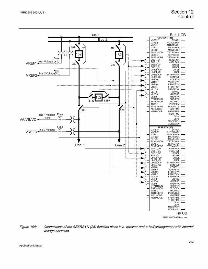
Tie CB
Bus 1 CB
ANSI10000097-1-en.vsd
VREF1
VREF2
bus1 Voltage
bus 2Voltage
line 1 Voltage1/2/3
line 2 Voltage
989989
Line 1 Line 2
VREF3
Bus 1Bus 2
289
189
152
289
189
152FuseVT
FuseVT
6189 6289152
FuseVT
FuseVT
VA/VB/VC
SESRSYN (25)V3PB1*V3PB2*V3PL1*V3PL2*BLOCKBLKSYNCHBLKSCBLKENERGBUS1_OPBUS1_CLBUS2_OPBUS2_CLLINE1_OPLINE1_CLLINE2_OPLINE2_CLVB1OKVB1FFVB2OKVB2FFVL1OKVL1FFVL2OKVL2FFSTARTSYNTSTSYNCHTSTSCTSTENERGAENMODEMENMODE
SYNOKAUTOSYOKAUTOENOK
MANSYOKMANENOK
TSTSYNOKTSTAUTSYTSTMANSY
TSTENOKVSELFAIL
B1SELB2SELL1SELL2SEL
SYNPROGRSYNFAILVOKSYN
VDIFFSYNFRDIFSYNFRDIFFOKFRDERIVA
VOKSCVDIFFSCFRDIFFAPHDIFFAFRDIFFMPHDIFFM
INADVCLSVDIFFME
FRDIFFMEPHDIFFME
VbusVLine
MODEAENMODEMEN
SESRSYN (25)V3PB1*V3PB2*V3PL1*V3PL2*BLOCKBLKSYNCHBLKSCBLKENERGBUS1_OPBUS1_CLBUS2_OPBUS2_CLLINE1_OPLINE1_CLLINE2_OPLINE2_CLVB1OKVB1FFVB2OKVB2FFVL1OKVL1FFVL2OKVL2FFSTARTSYNTSTSYNCHTSTSCTSTENERGAENMODEMENMODE
SYNOKAUTOSYOKAUTOENOK
MANSYOKMANENOK
TSTSYNOKTSTAUTSYTSTMANSY
TSTENOKVSELFAIL
B1SELB2SELL1SELL2SEL
SYNPROGRSYNFAILVOKSYN
VDIFFSYNFRDIFSYNFRDIFFOKFRDERIVA
VOKSCVDIFFSCFRDIFFAPHDIFFAFRDIFFMPHDIFFM
INADVCLSVDIFFME
FRDIFFMEPHDIFFME
VbusVLine
MODEAENMODEMEN
ANSI10000097 V1 EN
Figure 109: Connections of the SESRSYN (25) function block in a breaker-and-a-half arrangement with internalvoltage selection
1MRK 505 302-UUS - Section 12Control
283Application Manual

The connections are similar in all SESRSYN functions, apart from the breaker positionindications. The physical analog connections of voltages and the connection to the IEDand SESRSYN (25) function blocks must be carefully checked in PCM600. In allSESRSYN functions the connections and configurations must abide by the followingrules: Normally apparatus position is connected with contacts showing both open (b-type) and closed positions (a-type).
WA1_QA1:
• BUS1_OP/CL = Position of TIE_QA1 breaker and belonging disconnectors• BUS2_OP/CL = Position of WA2_QA1 breaker and belonging disconnectors• LINE1_OP/CL = Position of LINE1_QB9 disconnector• LINE2_OP/CL = Position of LINE2_QB9 disconnector• VB1OK/FF = Supervision of WA1_MCB fuse• VB2OK/FF = Supervision of WA2_MCB fuse• VL1OK/FF = Supervision of LINE1_MCB fuse• VL2OK/FF = Supervision of LINE2_MCB fuse• Setting CBConfig = 1 1/2 bus CB
TIE_QA1:
• BUS1_OP/CL = Position of WA1_QA1 breaker and belonging disconnectors• BUS2_OP/CL = Position of WA2_QA1 breaker and belonging disconnectors• LINE1_OP/CL = Position of LINE1_QB9 disconnector• LINE2_OP/CL = Position of LINE2_QB9 disconnector• VB1OK/FF = Supervision of WA1_MCB fuse• VB2OK/FF = Supervision of WA2_MCB fuse• VL1OK/FF = Supervision of LINE1_MCB fuse• VL2OK/FF = Supervision of LINE2_MCB fuse• Setting CBConfig = Tie CB
WA2_QA1:
• BUS1_OP/CL = Position of WA1_QA1 breaker and belonging disconnectors• BUS2_OP/CL = Position of TIE_QA1 breaker and belonging disconnectors• LINE1_OP/CL = Position of LINE1_QB9 disconnector• LINE2_OP/CL = Position of LINE2_QB9 disconnector• VB1OK/FF = Supervision of WA1_MCB fuse• VB2OK/FF = Supervision of WA2_MCB fuse• VL1OK/FF = Supervision of LINE1_MCB fuse• VL2OK/FF = Supervision of LINE2_MCB fuse• Setting CBConfig = 1 1/2 bus alt. CB
If only two SESRSYN functions are provided in the same IED, the connections andsettings are according to the SESRSYN functions for WA1_QA1 and TIE_QA1.
Section 12 1MRK 505 302-UUS -Control
284Application Manual

12.1.4 Setting guidelinesThe setting parameters for the Synchronizing, synchronism check and energizing checkfunction SESRSYN (25) are set via the local HMI (LHMI) or PCM600.
This setting guidelines describes the settings of the SESRSYN (25) function via theLHMI.
Common base IED value for primary voltage ( VBase ) is set in a Global base valuefunction, GBASVAL, found under Main menu//Configuration/Power system/GlobalBaseValue/GBASVAL_X/VBase. The SESRSYN (25) function has onesetting for the bus reference voltage (GblBaseSelBus) and one setting for the linereference voltage (GblBaseSelLine) which independently of each other can be set toselect one of the twelve GBASVAL functions used for reference of base values. Thismeans that the reference voltage of bus and line can be set to different values. Thesettings for the SESRSYN (25) function are found under Main menu/Settings/IEDSettings/Control/Synchronizing(25,SC/VC)/SESRSYN(25,SC/VC):X has beendivided into four different setting groups: General, Synchronizing, Synchrocheck andEnergizingcheck.
General settingsOperation: The operation mode can be set Enabled or Disabled. The setting Disableddisables the whole function.
GblBaseSelBus and GblBaseSelLine
These configuration settings are used for selecting one of twelve GBASVAL functions,which then is used as base value reference voltage, for bus and line respectively.
SelPhaseBus1 and SelPhaseBus2
Configuration parameters for selecting the measuring phase of the voltage for busbar 1and 2 respectively, which can be a single-phase (phase-neutral), two-phase (phase-phase) or a positive sequence voltage.
SelPhaseLine1 and SelPhaseLine2
Configuration parameters for selecting the measuring phase of the voltage for line 1and 2 respectively, which can be a single-phase (phase-neutral), two-phase (phase-phase) or a positive sequence voltage.
CBConfig
This configuration setting is used to define type of voltage selection. Type of voltageselection can be selected as:
1MRK 505 302-UUS - Section 12Control
285Application Manual
• no voltage selection, No voltage sel.• single circuit breaker with double bus, Double bus• breaker-and-a-half arrangement with the breaker connected to busbar 1, 1 1/2 bus
CB• breaker-and-a-half arrangement with the breaker connected to busbar 2, 1 1/2 bus
alt. CB• breaker-and-a-half arrangement with the breaker connected to line 1 and 2, Tie CB
PhaseShift
This setting is used to compensate for a phase shift caused by a power transformerbetween the two measurement points for bus voltage and line voltage. The set value isadded to the measured line phase angle. The bus voltage is reference voltage.
Synchronizing settingsOperationSynch
The setting Off disables the Synchronizing function. With the setting On, the functionis in the service mode and the output signal depends on the input conditions.
VHighBusSynch and VHighLineSynch
The voltage level settings shall be chosen in relation to the bus/line network voltage.The threshold voltages VHighBusSynch and VHighLineSynch have to be set lower thanthe value where the network is expected to be synchronized. A typical value is 80% ofthe rated voltage.
VDiffSynch
Setting of the voltage difference between the line voltage and the bus voltage. Thedifference is set depending on the network configuration and expected voltages in thetwo networks running asynchronously. A normal setting is 0.10-0.15 p.u.
FreqDiffMin
The setting FreqDiffMin is the minimum frequency difference where the systems aredefined to be asynchronous. For frequency differences lower than this value, thesystems are considered to be in parallel. A typical value for FreqDiffMin is 10 mHz.Generally, the value should be low if both synchronizing and synchrocheck functionsare provided, and it is better to let the synchronizing function close, as it will close atexactly the right instance if the networks run with a frequency difference.
To avoid overlapping of the synchronizing function and thesynchrocheck function the setting FreqDiffMin must be set to a higher
Section 12 1MRK 505 302-UUS -Control
286Application Manual
value than used setting FreqDiffM, respective FreqDiffA used forsynchrocheck.
FreqDiffMax
The setting FreqDiffMax is the maximum slip frequency at which synchronizing isaccepted. 1/FreqDiffMax shows the time for the vector to move 360 degrees, one turnon the synchronoscope, and is called Beat time. A typical value for FreqDiffMax is200-250 mHz, which gives beat times on 4-5 seconds. Higher values should be avoidedas the two networks normally are regulated to nominal frequency independent of eachother, so the frequency difference shall be small.
FreqRateChange
The maximum allowed rate of change for the frequency.
tBreaker
The tBreaker shall be set to match the closing time for the circuit breaker and shouldalso include the possible auxiliary relays in the closing circuit. It is important to checkthat no slow logic components are used in the configuration of the IED as there thencan be big variations in closing time due to those components. Typical setting is80-150 ms depending on the breaker closing time.
tClosePulse
The setting for the duration of the breaker close pulse.
tMaxSynch
The setting tMaxSynch is set to reset the operation of the synchronizing function if theoperation does not take place within this time. The setting must allow for the setting ofFreqDiffMin, which will decide how long it will take maximum to reach phaseequality. At the setting of 10 mHz, the beat time is 100 seconds and the setting wouldthus need to be at least tMinSynch plus 100 seconds. If the network frequencies areexpected to be outside the limits from the start, a margin needs to be added. A typicalsetting is 600 seconds.
tMinSynch
The setting tMinSynch is set to limit the minimum time at which the synchronizingclosing attempt is given. The synchronizing function will not give a closing commandwithin this time, from when the synchronizing is started, even if a synchronizingcondition is fulfilled. A typical setting is 200 ms.
1MRK 505 302-UUS - Section 12Control
287Application Manual

Synchrocheck settingsOperationSC
The OperationSC setting Off disables the synchrocheck function and sets the outputsAUTOSYOK, MANSYOK, TSTAUTSY and TSTMANSY to low. With the settingOn, the function is in the service mode and the output signal depends on the inputconditions.
VHighBusSC and VHighLineSC
The voltage level settings must be chosen in relation to the bus or line network voltage.The threshold voltages VHighBusSC and VHighLineSC have to be set lower than thevalue at which the breaker is expected to close with the synchronism check. A typicalvalue can be 80% of the base voltages.
VDiffSC
The setting for voltage difference between line and bus in p.u. This setting in p.u. isdefined as (V-Bus/GblBaseSelBus) - (V-Line/GblBaseSelLine). A normal setting is0,10-0,15 p.u.
FreqDiffM and FreqDiffA
The frequency difference level settings, FreqDiffM and FreqDiffA, shall be chosendepending on the condition in the network. At steady conditions a low frequencydifference setting is needed, where the FreqDiffM setting is used. For autoreclosing abigger frequency difference setting is preferable, where the FreqDiffA setting is used.A typical value for FreqDiffM can be10 mHz, and a typical value for FreqDiffA can be100-200 mHz.
PhaseDiffM and PhaseDiffA
The phase angle difference level settings, PhaseDiffM and PhaseDiffA, shall also bechosen depending on conditions in the network. The phase angle setting must bechosen to allow closing under maximum load condition. A typical maximum value inheavy-loaded networks can be 45 degrees, whereas in most networks the maximumoccurring angle is below 25 degrees. The PhaseDiffM setting is a limitation toPhaseDiffA setting. Fluctuations occurring at high speed autoreclosing limitPhaseDiffA setting.
tSCM and tSCA
The purpose of the timer delay settings, tSCM and tSCA, is to ensure that thesynchrocheck conditions remains constant and that the situation is not due to atemporary interference. Should the conditions not persist for the specified time, thedelay timer is reset and the procedure is restarted when the conditions are fulfilledagain. Circuit breaker closing is thus not permitted until the synchrocheck situation has
Section 12 1MRK 505 302-UUS -Control
288Application Manual

remained constant throughout the set delay setting time. Manual closing is normallyunder more stable conditions and a longer operation time delay setting is needed,where the tSCM setting is used. During auto-reclosing, a shorter operation time delaysetting is preferable, where the tSCA setting is used. A typical value for tSCM can be 1second and a typical value for tSCA can be 0.1 seconds.
Energizingcheck settingsAutoEnerg and ManEnerg
Two different settings can be used for automatic and manual closing of the circuitbreaker. The settings for each of them are:
• Disabled, the energizing function is disabled.• DLLB, Dead Line Live Bus, the line voltage is below set value of
VDeadLineEnerg and the bus voltage is above set value of VLIveBusEnerg.• DBLL, Dead Bus Live Line, the bus voltage is below set value of VDeadBusEnerg
and the line voltage is above set value of VLiveLineEnerg.• Both, energizing can be done in both directions, DLLB or DBLL.
ManEnergDBDL
If the parameter is set to Enabled, manual closing is also enabled when both linevoltage and bus voltage are below VDeadLineEnerg and VDeadBusEnerg respectively,and ManEnerg is set to DLLB, DBLL or Both.
VLiveBusEnerg and VLiveLineEnerg
The voltage level settings must be chosen in relation to the bus or line network voltage.The threshold voltages VLiveBusEnerg and VLiveLineEnerg have to be set lower thanthe value at which the network is considered to be energized. A typical value can be80% of the base voltages.
VDeadBusEnerg and VDeadLineEnerg
The threshold voltages VDeadBusEnerg and VDeadLineEnerg, have to be set to avalue greater than the value where the network is considered not to be energized. Atypical value can be 40% of the base voltages.
A disconnected line can have a considerable potential due to, forinstance, induction from a line running in parallel, or by being fed viathe extinguishing capacitors in the circuit breakers. This voltage can beas high as 30% or more of the base line voltage.
1MRK 505 302-UUS - Section 12Control
289Application Manual

Because the setting ranges of the threshold voltages VLiveBusEnerg/VLiveLineEnergand VDeadBusEnerg/VDeadLineEnerg partly overlap each other, the setting conditionsmay be such that the setting of the non-energized threshold value is higher than that ofthe energized threshold value. The parameters must therefore be set carefully to avoidoverlapping.
VMaxEnerg
This setting is used to block the closing when the voltage on the live side is above theset value of VMaxEnerg.
tAutoEnerg and tManEnerg
The purpose of the timer delay settings, tAutoEnerg and tManEnerg, is to ensure thatthe dead side remains de-energized and that the condition is not due to a temporaryinterference. Should the conditions not persist for the specified time, the delay timer isreset and the procedure is restarted when the conditions are fulfilled again. Circuitbreaker closing is thus not permitted until the energizing condition has remainedconstant throughout the set delay setting time.
12.2 Autorecloser for 1 phase, 2 phase and/or 3 phaseoperation SMBRREC (79)
12.2.1 IdentificationFunction Description IEC 61850
identificationIEC 60617identification
ANSI/IEEE C37.2device number
Autorecloser for 1 phase, 2 phase and/or 3 phase
SMBRREC
O->I
SYMBOL-L V1 EN
79
12.2.2 ApplicationIn certain countries it is standard practice to provide delayed restoration after busbarprotection operation for internal fault, reason being that many busbar faults are of thetransient natures that is, animals, birds, storm, flying objects, etc. In such applications,typically one pre-selected feeder is automatically closed with certain time delay inorder to try to re-energize the faulty bus. Typically, the longest overhead line isselected in order to limit the fault current in case of permanent busbar fault. If the first
Section 12 1MRK 505 302-UUS -Control
290Application Manual

feeder is successfully closed, all other feeder which have been connected to the samebus, are automatically put back into service.
Sensitive differential protection level available in REB670 can be used during suchoperation, if increased sensitivity from busbar protection is required. Such busbarrestoration logic can be implemented by using optionally available autoreclosingfunctions and built-in logical gates. Two autoreclosing functions are available, one foreach zone.
Automatic reclosing is a well-established method for the restoration of service in apower system after a transient line fault. The majority of line faults are flashover arcs,which are transient by nature. When the power line is switched off by the operation ofline protection and line breakers, the arc de-ionizes and recovers its ability to withstandvoltage at a somewhat variable rate. Thus, a certain dead time with a de-energized lineis necessary. Line service can then be resumed by automatic reclosing of the linebreakers. The dead time selected should be long enough to ensure a high probability ofarc de-ionization and successful reclosing.
For individual line breakers, auto-reclosing equipment, the auto-reclosing open time isused to determine line “dead time”. When simultaneous tripping and reclosing at thetwo line ends occurs, auto-reclosing open time is approximately equal to the line “deadtime”. If the open time and dead time differ then, the line will be energized until thebreakers at both ends have opened.
1MRK 505 302-UUS - Section 12Control
291Application Manual

en04000146_ansi.vsd
Open
Closed
Operate time
Lineprotection
Circuitbreaker
Break time
Trip
com
man
d
Con
tact
s se
para
ted
Are
extin
guis
hers
Fault duration AR open time for breaker Fault durationR
eset
s
Inst
ant o
f fau
lt
Ope
rate
s
Break timeClosing time
Operate time
Faul
t
Ope
rate
s
Res
ets
Clo
se c
omm
and
Con
tact
clo
sed
Set AR open timeAuto-reclosing
functionR
eclo
sing
com
man
d
AR re
set
Initi
ate
AR
Reset time
ANSI04000146 V1 EN
Figure 110: Single-shot automatic reclosing at a permanent fault
Single-pole tripping and single-phase automatic reclosing is a way of limiting theeffect of a single-phase line fault on power system operation. Especially at highervoltage levels, the majority of faults are of single-phase type (around 90%). Tomaintain system stability in power systems with limited meshing or parallel routingsingle phase auto reclosing is of particular value. During the single phase dead time thesystem is still capable of transmitting load on the two healthy phases and the system isstill synchronized. It requires that each phase breaker operates individually, which isusually the case for higher transmission voltages.
A somewhat longer dead time may be required for single-phase reclosing compared tohigh-speed three-phase reclosing. This is due to the influence on the fault arc from thevoltage and the current in the non-tripped phases.
To maximize the availability of the power system it is possible to choose single poletripping and automatic reclosing during single-phase faults and three pole tripping andautomatic reclosing during multi-phase faults. Three-phase automatic reclosing can beperformed with or without the use of a synchronism check, and an energizing check,such as dead line or dead busbar check.
Section 12 1MRK 505 302-UUS -Control
292Application Manual

During the single-pole open time there is an equivalent "series"-fault in the systemresulting in a flow of zero sequence current. It is therefore necessary to coordinate theresidual current protections (ground fault protection) with the single pole tripping andthe auto-reclosing function. Attention shall also be paid to “pole discrepancy” thatarises when circuit breakers are provided with single pole operating devices. Thesebreakers need pole discrepancy protection. They must also be coordinated with thesingle pole auto-recloser and blocked during the dead time when a normal discrepancyoccurs. Alternatively, they should use a trip time longer than the set single phase deadtime.
For the individual line breakers and auto-reclosing equipment, the ”auto-reclosing opentime” expression is used. This is the dead time setting for the Auto-Recloser. Duringsimultaneous tripping and reclosing at the two line ends, auto-reclosing open time isapproximately equal to the line dead time. Otherwise these two times may differ as oneline end might have a slower trip than the other end which means that the line will notbe dead until both ends have opened.
If the fault is permanent, the line protection will trip again when reclosing is attemptedin order to clear the fault.
It is common to use one automatic reclosing function per line circuit-breaker (CB).When one CB per line end is used, then there is one auto-reclosing function per lineend. If auto-reclosing functions are included in duplicated line protection, which meanstwo auto-reclosing functions per CB, one should take measures to avoid uncoordinatedreclosing commands. In breaker-and-a-half, double-breaker and ring bus arrangements,two CBs per line end are operated. One auto-reclosing function per CB isrecommended. Arranged in such a way, sequential reclosing of the two CBs can bearranged with a priority circuit available in the auto-reclose function. In case of apermanent fault and unsuccessful reclosing of the first CB, reclosing of the second CBis cancelled and thus the stress on the power system is limited. Another advantage withthe breaker connected auto-recloser is that checking that the breaker closed before thesequence, breaker prepared for an auto-reclose sequence and so on. is much simpler.
The auto-reclosing function can be selected to perform single-phase and/or three-phaseautomatic-reclosing from several single-shot to multiple-shot reclosing programs. Thethree-phase auto-reclosing open time can be set to give either High-Speed AutomaticReclosing (HSAR) or Delayed Automatic-Reclosing (DAR). These expressions,HSAR and DAR, are mostly used for three-phase Reclosing as single phase is alwayshigh speed to avoid maintaining the unsymmetrical condition. HSAR usually means adead time of less than 1 second.
In power transmission systems it is common practise to apply single and/or threephase, single-shot Auto-Reclosing. In Sub-transmission and Distribution systemstripping and auto-reclosing are usually three-phase. The mode of automatic-reclosingvaries however. Single-shot and multi-shot are in use. The first shot can have a shortdelay, HSAR, or a longer delay, DAR. The second and following reclosing shots have
1MRK 505 302-UUS - Section 12Control
293Application Manual

a rather long delay. When multiple shots are used the dead time must harmonize withthe breaker duty-cycle capacity.
Automatic-reclosing is usually started by the line protection and in particular byinstantaneous tripping of such protection. The auto-reclosing function can be inhibited(blocked) when certain protection functions detecting permanent faults, such as shuntreactor, cable or busbar protection are in operation. Back-up protection zonesindicating faults outside the own line are also connected to inhibit the Auto-Reclose.
Automatic-reclosing should not be attempted when closing a CB and energizing a lineonto a fault (SOTF), except when multiple-shots are used where shots 2 etc. will bestarted at SOTF. Likewise a CB in a multi-breaker busbar arrangement which was notclosed when a fault occurred should not be closed by operation of the Auto-Reclosingfunction. Auto-Reclosing is often combined with a release condition from synchronismcheck and dead line or dead busbar check. In order to limit the stress on turbo-generator sets from Auto-Reclosing onto a permanent fault, one can arrange tocombine Auto-Reclosing with a synchronism check on line terminals close to suchpower stations and attempt energizing from the side furthest away from the powerstation and perform the synchronism check at the local end if the energizing wassuccessful.
Transmission protection systems are usually sub-divided and provided with tworedundant protection IEDs. In such systems it is common to provide auto-reclosing inonly one of the sub-systems as the requirement is for fault clearance and a failure toreclose because of the auto-recloser being out of service is not considered a majordisturbance. If two auto-reclosers are provided on the same breaker, the applicationmust be carefully checked and normally one must be the master and be connected toinhibit the other auto-recloser if it has started. This inhibit can for example be donefrom Autorecloser for 3-phase operation(SMBRREC ,79) In progress.
When Single and/or three phase auto-reclosing is considered, there are a number ofcases where the tripping shall be three phase anyway. For example:
• Evolving fault where the fault during the dead-time spreads to another phase. Theother two phases must then be tripped and a three phase dead-time and auto-reclose initiated
• Permanent fault• Fault during three phase dead-time• Auto-reclose out of service or CB not ready for an auto-reclosing cycle
“Prepare three-pole tripping” is then used to switch the tripping to three-pole. Thissignal is generated by the auto-recloser and connected to the trip function block andalso connected outside the IED through IO when a common auto-recloser is providedfor two sub-systems. An alternative signal “Prepare 1 Pole tripping” is also providedand can be used as an alternative when the autorecloser is shared with another
Section 12 1MRK 505 302-UUS -Control
294Application Manual

subsystem. This provides a fail safe connection so that even a failure in the IED withthe auto-recloser will mean that the other sub-system will start a three-pole trip.
A permanent fault will cause the line protection to trip again when it recloses in anattempt to energize the line.
The auto-reclosing function allows a number of parameters to be adjusted.
Examples:
• number of auto-reclosing shots• auto-reclosing program• auto-reclosing open times (dead time) for each shot
12.2.2.1 Auto-reclosing operation OFF and ON
Operation of the automatic reclosing can be set OFF and ON by a setting parameterand by external control. Parameter Operation= Disabled, or Enabled sets the functionOFF and ON. With the settings Operation = Enabled and ExternalCtrl = Enabled , thecontrol is made by input signal pulses to the inputs ON and OFF, for example, from thecontrol system or from the binary input (and other systems).
When the function is set ON, the output SETON is set, and it become operative if otherconditions such as CB closed and CB Ready are also fulfilled, the output READY isactivated (high). When the function is ready to accept a reclosing start.
12.2.2.2 Initiate auto-reclosing and conditions for initiation of a reclosing cycle
The usual way to start a reclosing cycle, or sequence, is to start it at selective trippingby line protection by applying a signal to the input RI. Starting signals can be either,General Trip signals or, only the conditions for Differential, Distance protection Zone1 and Distance protection Aided trip. In some cases also Directional Ground faultfunction Aided trip can be connected to start an Auto-Reclose attempt. If general trip isused to start the auto- recloser it is important to block it from other functions thatshould not start a reclosing sequence.
In cases where one wants to differentiate three-phase “auto-reclosing open time”,(“dead time”) for different power system configuration or at tripping by differentprotection stages, one can also use the input RI_HS (Initiate High-Speed Reclosing).When initiating RI_HS, the auto-reclosing open time for three-phase shot 1, t1 3PhHSis used and the closing is done without checking the synchrocheck condition.
A number of conditions need to be fulfilled for the start to be accepted and a new auto-reclosing cycle to be started. They are linked to dedicated inputs. The inputs are:
1MRK 505 302-UUS - Section 12Control
295Application Manual

• CBREADY, CB ready for a reclosing cycle, for example, charged operating gear.• 52a to ensure that the CB was closed when the line fault occurred and start was
applied.• No signal at input INHIBIT that is, no blocking or inhibit signal present. After the
start has been accepted, it is latched in and an internal signal “Started” is set. It canbe interrupted by certain events, like an “Inhibit” signal.
12.2.2.3 Initiate auto-reclosing from CB open information
If a user wants to initiate auto-reclosing from the "CB open" position instead of fromprotection trip signals, the function offers such a possibility. This starting mode isselected with the setting parameter StartByCBOpen=Enabled. It is then necessary toblock reclosing for all manual trip operations. Typically CBAuxContType=NormClosedis also set and a CB auxiliary contact of type NC (normally closed, 52b) is connectedto inputs 52a and RI. When the signal changes from “CB closed” to “CB open” an auto-reclosing start pulse is generated and latched in the function, subject to the usualchecks. Then the reclosing sequence continues as usual. One needs to connect signalsfrom manual tripping and other functions, which shall not be reclosed automatically tothe input INHIBIT.
12.2.2.4 Blocking of the autorecloser
Auto-Reclose attempts are expected to take place only for faults on the own line. TheAuto-Recloser must be blocked by activating the INHIBIT input for the followingconditions:
• Tripping from Delayed Distance protection zones• Tripping from Back-up protection functions• Tripping from Breaker failure function• Intertrip received from remote end Breaker failure function• Busbar protection tripping
Depending of the starting principle (General Trip or only Instantaneous trip) adoptedabove the delayed and back-up zones might not be required. Breaker failure trip localand remote must however always be connected.
12.2.2.5 Control of the auto-reclosing open time for shot 1
Up to four different time settings can be used for the first shot, and one extension time.There are separate settings for single-, two- and three-phase auto-reclosing open time,t1 1Ph, t1 2Ph, t1 3Ph. If no particular input signal is applied, and an auto-reclosingprogram with single-phase reclosing is selected, the auto-reclosing open time t1 1Phwill be used. If one of the inputs TR2P or TR3P is activated in connection with the
Section 12 1MRK 505 302-UUS -Control
296Application Manual

start, the auto-reclosing open time for two-phase or three-phase reclosing is used.There is also a separate time setting facility for three-phase high-speed auto-reclosingwithout Synchrocheck, t1 3PhHS, available for use when required. It is activated by theRI_HS input.
An auto-reclosing open time extension delay, tExtended t1, can be added to the normalshot 1 delay. It is intended to come into use if the communication channel forpermissive line protection is lost. In such a case there can be a significant timedifference in fault clearance at the two ends of the line. A longer “auto-reclosing opentime” can then be useful. This extension time is controlled by setting parameterExtended t1=On and the input PLCLOST. If this function is used the autorecloser startmust also be allowed from distance protection Zone 2 time delayed trip.
12.2.2.6 Long trip signal
In normal circumstances the trip command resets quickly because of fault clearance.The user can set a maximum trip pulse duration tTrip.If Extended t1=Off, a long tripsignal interrupts the reclosing sequence in the same way as a signal to input INHIBIT.If Extend t1=On the long trip time inhibit is disabled and Extend t1 is used instead.
12.2.2.7 Maximum number of reclosing shots
The maximum number of reclosing shots in an auto-reclosing cycle is selected by thesetting parameter NoOfShots. The type of reclosing used at the first reclosing shot is setby parameter ARMode. The first alternative is three-phase reclosing. The otheralternatives include some single-phase or two-phase reclosing. Usually there is no two-pole tripping arranged, and then there will be no two-phase reclosing.
The decision for single and 3 phase trip is also made in the tripping logic (SMPTTRC ,94) function block where the setting 3Ph, 1/3Ph (or1/2/3Ph) is selected.
12.2.2.8 ARMode=3ph, (normal setting for a single 3 phase shot)
3-phase reclosing, one to five shots according to setting NoOfShots. The output Preparethree-pole trip PREP3P is always set (high). A trip operation is made as a three-poletrip at all types of fault. The reclosing is as a three-phase Reclosing as in mode 1/2/3phdescribed below. All signals, blockings, inhibits, timers, requirements and so on. arethe same as in the example described below.
12.2.2.9 ARMode=1/2/3ph
1-phase, 2-phase or 3-phase reclosing first shot, followed by 3-phase reclosing shots, ifselected. Here, the auto-reclosing function is assumed to be "On" and "Ready". Thebreaker is closed and the operation gear ready (operating energy stored). Input RI (or
1MRK 505 302-UUS - Section 12Control
297Application Manual
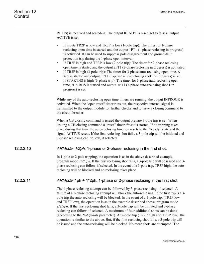
RI_HS) is received and sealed-in. The output READY is reset (set to false). OutputACTIVE is set.
• If inputs TR2P is low and TR3P is low (1-pole trip): The timer for 1-phasereclosing open time is started and the output 1PT1 (1-phase reclosing in progress)is activated. It can be used to suppress pole disagreement and ground-faultprotection trip during the 1-phase open interval.
• If TR2P is high and TR3P is low (2-pole trip): The timer for 2-phase reclosingopen time is started and the output 2PT1 (2-phase reclosing in progress) is activated.
• If TR3P is high (3-pole trip): The timer for 3-phase auto-reclosing open time, t13Ph is started and output 3PT1 (3-phase auto-reclosing shot 1 in progress) is set.
• If STARTHS is high (3-phase trip): The timer for 3-phase auto-reclosing opentime, t1 3PhHS is started and output 3PT1 (3-phase auto-reclosing shot 1 inprogress) is set.
While any of the auto-reclosing open time timers are running, the output INPROGR isactivated. When the "open reset" timer runs out, the respective internal signal istransmitted to the output module for further checks and to issue a closing command tothe circuit breaker.
When a CB closing command is issued the output prepare 3-pole trip is set. Whenissuing a CB closing command a “reset” timer tReset is started. If no tripping takesplace during that time the auto-reclosing function resets to the “Ready” state and thesignal ACTIVE resets. If the first reclosing shot fails, a 3-pole trip will be initiated and3-phase reclosing can follow, if selected.
12.2.2.10 ARMode=1/2ph, 1-phase or 2-phase reclosing in the first shot.
In 1-pole or 2-pole tripping, the operation is as in the above described example,program mode 1/2/3ph. If the first reclosing shot fails, a 3-pole trip will be issued and 3-phase reclosing can follow, if selected. In the event of a 3-pole trip, TR3P high, the auto-reclosing will be blocked and no reclosing takes place.
12.2.2.11 ARMode=1ph + 1*2ph, 1-phase or 2-phase reclosing in the first shot
The 1-phase reclosing attempt can be followed by 3-phase reclosing, if selected. Afailure of a 2-phase reclosing attempt will block the auto-reclosing. If the first trip is a 3-pole trip the auto-reclosing will be blocked. In the event of a 1-pole trip, (TR2P lowand TR3P low), the operation is as in the example described above, program mode1/2/3ph. If the first reclosing shot fails, a 3-pole trip will be initiated and 3-phasereclosing can follow, if selected. A maximum of four additional shots can be done(according to the NoOfShots parameter). At 2-pole trip (TR2P high and TR3P low), theoperation is similar to the above. But, if the first reclosing shot fails, a 3-pole trip willbe issued and the auto-reclosing will be blocked. No more shots are attempted! The
Section 12 1MRK 505 302-UUS -Control
298Application Manual

expression 1*2ph should be understood as “Just one shot at 2-phase reclosing” During3-pole trip (TR2P low and TR3P high) the auto-reclosing will be blocked and noreclosing takes place.
12.2.2.12 ARMode=1/2ph + 1*3ph, 1-phase, 2-phase or 3-phase reclosing in thefirst shot
At 1-phase or 2-phase trip, the operation is as described above. If the first reclosingshot fails, a 3-phase trip will be issued and 3-phase reclosing will follow, if selected.At 3-phase trip, the operation is similar to the above. But, if the first reclosing shotfails, a 3-phase trip command will be issued and the auto-reclosing will be blocked. Nomore shots take place! 1*3ph should be understood as “Just one shot at 3-phase reclosing”.
12.2.2.13 ARMode=1ph + 1*2/3ph, 1-phase, 2-phase or 3-phase reclosing in thefirst shot
At 1-pole trip, the operation is as described above. If the first reclosing shot fails, a 3-pole trip will be issued and 3-phase reclosing will follow, if selected. At 2-pole or 3-pole trip, the operation is similar as above. But, if the first reclosing shot fails, a 3-poletrip will be issued and the auto-reclosing will be blocked. No more shots take place!“1*2/3ph” should be understood as “Just one shot at 2-phase or 3-phase reclosing”.
Table 32: Type of reclosing shots at different settings of ARMode or integer inputs to MODEINT
MODEINT (integer) ARMode Type of fault 1st shot 2nd-5th shot
1 3ph
1ph 3ph 3ph
2ph 3ph 3ph
3ph 3ph 3ph
2 1/2/3ph
1ph 1ph 3ph
2ph 2ph 3ph
3ph 3ph 3ph
3 1/2ph
1ph 1ph 3ph
2ph 2ph 3ph
3ph ..... .....
4 1ph + 1*2ph
1ph 1ph 3ph
2ph 2ph .....
3ph ..... .....
5 1/2ph + 1*3ph
1ph 1ph 3ph
2ph 2ph 3ph
3ph 3ph .....
Table continues on next page
1MRK 505 302-UUS - Section 12Control
299Application Manual

MODEINT (integer) ARMode Type of fault 1st shot 2nd-5th shot
6 1ph + 1*2/3ph
1ph 1ph 3ph
2ph 2ph .....
3ph 3ph .....
A start of a new reclosing cycle is blocked during the set “reset time” after the selectednumber of reclosing shots have been made.
12.2.2.14 External selection of auto-reclose mode
The auto-reclose mode can be selected by use of the available logic function blocks.Below is an example where the choice of mode is done from a hardware function keyin front of the IED with only 3 phase or 1/3 phase mode, but alternatively there can forexample, be a physical selector switch on the front of the panel which is connected to abinary to integer function block (BTIGAPC).
The connection example for selection of the auto-reclose mode is shown in Figure .
ANSI09000168_1_en.vsd
SMBRREC (79)MODEINT
PSTO
SWPOSNNAME1NAME2
31/3
INTONE
SLGGIO
ANSI09000168 V1 EN
Figure 111: Selection of the auto-reclose mode from a hardware functional key infront of the IED
12.2.2.15 Reclosing reset timer
The reset timer tReset defines the time it takes from issue of the reclosing command,until the reclosing function resets. Should a new trip occur during this time, it is treatedas a continuation of the first fault. The reclaim timer is started when the CB closingcommand is given.
12.2.2.16 Pulsing of the CB closing command and Counter
The CB closing command, CLOSECMD is given as a pulse with a duration set byparameter tPulse. For circuit-breakers without an anti-pumping function, close pulsecutting can be used. It is selected by parameter CutPulse=On. In case of a new trip
Section 12 1MRK 505 302-UUS -Control
300Application Manual

pulse (start), the closing command pulse is then cut (interrupted). The minimumclosing pulse length is always 50 ms. At the issue of the Reclosing command, theappropriate Reclosing operation counter is incremented. There is a counter for eachtype of Reclosing and one for the total number of Reclosing commands.
12.2.2.17 Transient fault
After the Reclosing command the reset timer keeps running for the set time. If notripping occurs within this time, tReset, the Auto-Reclosing will reset. The CB remainsclosed and the operating gear recharges. The input signals 52a and CBREADY will beset
12.2.2.18 Permanent fault and reclosing unsuccessful signal
If a new trip occurs, and number of reclosing shots is set to 1, a new input signal RI orTRSOTF appears, after the CB closing command, the output UNSUCCL (unsuccessfulclosing) is set high. The timer for the first shot can no longer be started. Depending onthe set number of Reclosing shots further shots may be made or the Reclosingsequence is ended. After reset timer time-out the Auto-Reclosing function resets, butthe CB remains open. The “CB closed” information through the input 52a is missing.Thus, the reclosing function is not ready for a new reclosing cycle.
Normally, the signal UNSUCCL appears when a new trip and start is received after thelast reclosing shot has been made and the auto-reclosing function is blocked. Thesignal resets after reset time. The “unsuccessful” signal can also be made to depend onCB position input. The parameter UnsucClByCBChk should then be set to CBCheck,and a timer tUnsucCl should be set too. If the CB does not respond to the closingcommand and does not close, but remains open, the output UNSUCCL is set high aftertime tUnsucCl. The Unsuccessful output can for example, be used in Multi-Breakerarrangement to cancel the auto-reclosing function for the second breaker, if the firstbreaker closed onto a persistent fault. It can also be used to generate a Lock-out ofmanual closing until the operator has reset the Lock-out, see separate section.
12.2.2.19 Lock-out initiation
In many cases there is a requirement that a Lock-out is generated when the auto-reclosing attempt fails. This is done with logic connected to the in- and outputs of theAutoreclose function and connected to Binary IO as required. Many alternative waysof performing the logic exist depending on whether manual closing is interlocked inthe IED, whether an external physical Lock-out relay exists and whether the reset ishardwired, or carried out by means of communication. There are also differentalternatives regarding what shall generate Lock-out. Examples of questions are:
1MRK 505 302-UUS - Section 12Control
301Application Manual
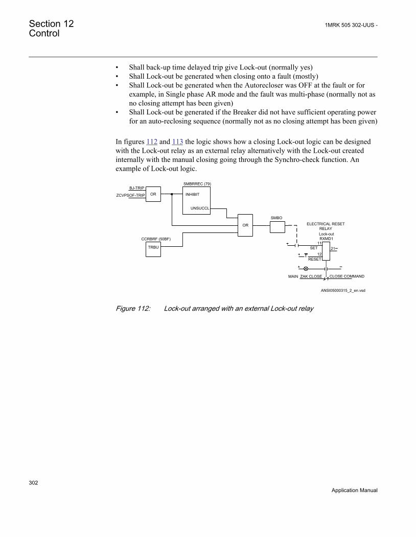
• Shall back-up time delayed trip give Lock-out (normally yes)• Shall Lock-out be generated when closing onto a fault (mostly)• Shall Lock-out be generated when the Autorecloser was OFF at the fault or for
example, in Single phase AR mode and the fault was multi-phase (normally not asno closing attempt has been given)
• Shall Lock-out be generated if the Breaker did not have sufficient operating powerfor an auto-reclosing sequence (normally not as no closing attempt has been given)
In figures 112 and 113 the logic shows how a closing Lock-out logic can be designedwith the Lock-out relay as an external relay alternatively with the Lock-out createdinternally with the manual closing going through the Synchro-check function. Anexample of Lock-out logic.
Lock-out RXMD1
11
1221
MAIN ZAK CLOSE CLOSE COMMAND
SMBO
OR
SMBRREC (79)
OR
CCRBRF (50BF)
BJ-TRIP
ZCVPSOF-TRIP INHIBIT
UNSUCCL
TRBU
ANSI05000315_2_en.vsd
SET
RESET
ELECTRICAL RESET RELAY
ANSI05000315 V2 EN
Figure 112: Lock-out arranged with an external Lock-out relay
Section 12 1MRK 505 302-UUS -Control
302Application Manual

CLOSE COMMAND
OR
SMBRREC (79)
OR
CCRBRF (50BF)
BJ-TRIP
ZCVPSOF-TRIP INHIBIT
UNSUCCL
BJTRIP
ANSI05000316_2_en.vsd
SMPPTRC (94)
SMBO
AND
RESET LOCK-OUT
OR
OR
SESRSYN (25)
SOFTWARE OR IO RESET
AUTO STOP
MAN ENOK
MAN CLOSE
SMBRREC (79) CLOSE
SETLKOUT
CLLOUT
RSTLOUT
ANSI05000316 V2 EN
Figure 113: Lock-out arranged with internal logic with manual closing going throughin IED
12.2.2.20 Evolving fault
An evolving fault starts as a single-phase fault which leads to single-pole tripping andthen the fault spreads to another phase. The second fault is then cleared by three-poletripping.
The Auto-Reclosing function will first receive a trip and initiate signal (RI) withoutany three-phase signal (TR3P). The Auto-Reclosing function will start a single-phasereclosing, if programmed to do so. At the evolving fault clearance there will be a newsignal RI and three-pole trip information, TR3P. The single-phase reclosing sequencewill then be stopped, and instead the timer, t1 3Ph, for three-phase reclosing will bestarted from zero. The sequence will continue as a three-phase reclosing sequence, if itis a selected alternative reclosing mode.
The second fault which can be single phase is tripped three phase because trip module(TR) in the IED has an evolving fault timer which ensures that second fault is alwaystripped three phase. For other types of relays where the relays do not include thisfunction the output PREP3PH (or the inverted PERMIT1PH) is used to prepare theother sub-system for three pole tripping. This signal will, for evolving fault situationsbe activated a short time after the first trip has reset and will thus ensure that new tripswill be three phase.
1MRK 505 302-UUS - Section 12Control
303Application Manual

12.2.2.21 Automatic continuation of the reclosing sequence
SMBRREC (79) function can be programmed to proceed to the following reclosingshots (if multiple shots are selected) even if start signals are not received from theprotection functions, but the breaker is still not closed. This is done by settingparameter AutoCont = Enabled and tAutoContWait to the required delay for thefunction to proceed without a new start.
12.2.2.22 Thermal overload protection holding the auto-reclosing function back
If the input THOLHOLD (thermal overload protection holding reclosing back) isactivated, it will keep the reclosing function on a hold until it is reset. There may thusbe a considerable delay between start of Auto-Reclosing and reclosing command to thecircuit-breaker. An external logic limiting the time and sending an inhibit to theINHIBIT input can be used. The input can also be used to set the Auto-Reclosing onhold for a longer or shorter period.
12.2.3 Setting guidelines
12.2.3.1 Configuration
Use the PCM600 configuration tool to configure signals.
Autorecloser function parameters are set via the local HMI or Parameter Setting Tool(PST). Parameter Setting Tool is a part of PCM600.
Recommendations for input signalsPlease see examples in figure 114, figure 115 and figure 116 of default factoryconfigurations.
ON and OFFThese inputs can be connected to binary inputs or to a communication interface blockfor external control.
RIIt should be connected to the trip output protection function, which starts theautorecloser for 1/2/3-phase operation (SMBRREC ,79) function. It can also beconnected to a binary input for start from an external contact. A logical OR-gate can beused to combine the number of start sources.
If StartByCBOpen is used, the CB Open condition shall also beconnected to the input RI.
Section 12 1MRK 505 302-UUS -Control
304Application Manual

RI_HS, Initiate High-speed auto-reclosingIt may be used when one wants to use two different dead times in different protectiontrip operations. This input starts the dead time t1 3PhHS. High-speed reclosing shot 1started by this input is without a synchronization check.
INHIBITTo this input shall be connected signals that interrupt a reclosing cycle or prevent astart from being accepted. Such signals can come from protection for a line connectedshunt reactor, from transfer trip receive, from back-up protection functions, busbarprotection trip or from breaker failure protection. When the CB open position is set tostart SMBRREC(79) , then manual opening must also be connected here. The inhibit isoften a combination of signals from external IEDs via the IO and internal functions. AnOR gate is then used for the combination.
52a and CBREADYThese should be connected to binary inputs to pick-up information from the CB. The52a input is interpreted as CB Closed, if parameter CBAuxContType is set NormOpen,which is the default setting. At three operating gears in the breaker (single poleoperated breakers) the connection should be “All poles closed” (series connection ofthe NO contacts) or “At least one pole open” (parallel connection of NC contacts) ifthe CBAuxContType is set to NormClosed. The “CB Ready” is a signal meaning thatthe CB is ready for a reclosing operation, either Close-Open (CO), or Open-Close-Open (OCO). If the available signal is of type “CB not charged” or “not ready”, aninverter can be inserted in front of the CBREADY input.
SYNCThis is connected to the internal synchronism check function when required. It can alsobe connected to a binary input for synchronization from an external device. If neitherinternal nor external synchronism or energizing check is required, it can be connectedto a permanently high source, TRUE. The signal is required for three phase shots 1-5 toproceed (Note! Not the HS step).
PLCLOSTThis is intended for line protection permissive signal channel lost (fail) for example,PLC= Power Line Carrier fail. It can be connected, when required to prolong theAutoReclosing time when communication is not working, that is, one line end mighttrip with a zone 2 delay. If this is used the autorecloser must also be started from Zone2time delayed trip.
1MRK 505 302-UUS - Section 12Control
305Application Manual
TRSOTFThis is the signal “Trip by Switch Onto Fault”. It is usually connected to the “switchonto fault” output of line protection if multi-shot Auto-Reclose attempts are used. Theinput will start the shots 2-5.
THOLHOLDSignal “Thermal overload protection holding back Auto-Reclosing”. It can beconnected to a thermal overload protection trip signal which resets only when thethermal content has fallen to an acceptable level, for example, 70%. As long as thesignal is high, indicating that the line is hot, the Auto-Reclosing is held back. When thesignal resets, a reclosing cycle will continue. Please observe that this have aconsiderable delay. Input can also be used for other purposes if for some reason the Auto-Reclose shot need to be halted.
TR2P and TR3PSignals for two-pole and three-pole trip. They are usually connected to thecorresponding output of the TRIP block. They control the choice of dead time and thereclosing cycle according to the selected program. Signal TR2P needs to be connectedonly if the trip has been selected to give 1/2/3 pole trip and an auto reclosing cycle withtwo phase reclosing is foreseen.
WAITUsed to hold back reclosing of the “low priority unit” during sequential reclosing. See“Recommendation for multi-breaker arrangement” below. The signal is activated fromoutput WFMASTER on the second breaker Auto-Recloser in multi-breakerarrangements.
BLKONUsed to block the autorecloser for 3-phase operation (SMBRREC ,79) function forexample, when certain special service conditions arise. When used, blocking must bereset with BLOCKOFF.
BLOCKOFFUsed to Unblock SMBRREC (79) function when it has gone to Block due to activatinginput BLKON or by an unsuccessful Auto-Reclose attempt if thesettingBlockByUnsucCl is set to Enabled.
RESETUsed to Reset SMBRREC (79) to start condition. Possible Thermal overload Hold willbe reset. Positions, setting On-Off. will be started and checked with set times.
Section 12 1MRK 505 302-UUS -Control
306Application Manual

Recommendations for output signalsPlease see figure 114, figure 115 and figure 116 and default factory configuration forexamples.
SETONIndicates that Autorecloser for 1/2/3-phase operation (SMBRREC ,79) function isswitched on and operative.
BLOCKEDIndicates that SMRREC (79) function is temporarily or permanently blocked.
ACTIVEIndicates that SMBRREC (79) is active, from start until end of Reset time.
INPROGRIndicates that a sequence is in progress, from start until reclosing command.
UNSUCCLIndicates unsuccessful reclosing.
CLOSECMDConnect to a binary output for circuit-breaker closing command.
READYIndicates that SMBRREC (79) function is ready for a new and complete reclosingsequence. It can be connected to the zone extension if a line protection should extendedzone reach before automatic reclosing.
1PT1 and 2PT1Indicates that single-phase or two-phase automatic reclosing is in progress. It is used totemporarily block an ground-fault and/or pole disagreement function during the single-phase or two-phase open interval.
3PT1, 3PT2, 3PT3, 3PT4 and 3PT5Indicates that three-phase automatic reclosing shots 1-5 are in progress. The signalscan be used as an indication of progress or for own logic.
PREP3PPrepare three-pole trip is usually connected to the trip block to force a coming trip tobe a three-phase one. If the function cannot make a single-phase or two-phasereclosing, the tripping should be three-pole.
1MRK 505 302-UUS - Section 12Control
307Application Manual

PERMIT1PPermit single-pole trip is the inverse of PREP3P. It can be connected to a binary outputrelay for connection to external protection or trip relays. In case of a total loss ofauxiliary power, the output relay drops and does not allow single-pole trip.
WFMASTERWait from master is used in high priority units to hold back reclosing of the lowpriority unit during sequential reclosing. Refer to the recommendation for multi-breaker arrangements in figure 116.
Other outputsThe other outputs can be connected for indication, disturbance recording, as required.
ANSI04000135_2_en.vsd
ONOFFBLKONBLOCKOFFINHIBIT
BLOCKEDSETON
INPROGRACTIVE
UNSUCCLSUCCL
CLOSECMD
1PT1
WFMASTER
RESET
RI
THOLHOLD
READY
TRSOTF
SYNC
INPUTxxxxxxxxxxxxxxxxxxxx
OR
OR
OUTPUTxxxxxxxxxxxxxxxxxxxx
PROTECTIONxxxx-TRIP
ZCVPSOF-TRIPZMQPDIS (21)--TRIP
SESRSYN (25)-AUTOOK
IOM IOMSMBRREC (79)
PERMIT1PPREP3P
F
FT
RI_HSSKIPHS
FF
TR2PTR3P
FT
WAITRSTCOUNT
FF
3PT12PT1
3PT23PT33PT43PT5
F
CBREADY52aPLCLOST
ANSI04000135 V2 EN
Figure 114: Example of I/O-signal connections at a three-phase reclosing function
Setting recommendations for multi-breaker arrangementsSequential reclosing in multi-breaker arrangements, like breaker-and-a-half, doublebreaker and ring bus, is achieved by giving the two line breakers different priorities.Please refer to figure 116. In a single breaker arrangement the setting is Priority =None. In a multi-breaker arrangement the setting for the first CB, the Master, isPriority = High and for the other CB Priority = Low.
Section 12 1MRK 505 302-UUS -Control
308Application Manual

While the reclosing of the master is in progress, it issues the signal WFMASTER. Areset delay of one second ensures that the WAIT signal is kept high for the duration ofthe breaker closing time. After an unsuccessful reclosing it is also maintained by thesignal UNSUCCL. In the slave unit, the signal WAIT holds back a reclosing operation.When the WAIT signal is reset at the time of a successful reclosing of the first CB, theslave unit is released to continue the reclosing sequence. A parameter tWait sets amaximum waiting time for the reset of the WAIT. At time-out it interrupts thereclosing cycle of the slave unit. If reclosing of the first breaker is unsuccessful, theoutput signal UNSUCCL connected to the input INHIBIT of the slave unit interruptsthe reclosing sequence of the latter.
The signals can be cross-connected to allow simple changing of thepriority by just setting the High and the Low priorities without changingthe configuration. The inputs 52a for each breaker are important inmulti breaker arrangements to ensure that the CB was closed at thebeginning of the cycle. If the High priority breaker is not closed theHigh priority moves to the low priority breaker.
1MRK 505 302-UUS - Section 12Control
309Application Manual
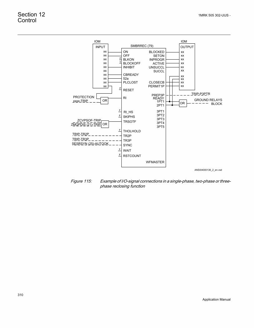
ANSI04000136_2_en.vsd
ONOFFBLKONBLOCKOFFINHIBIT
BLOCKEDSETON
INPROGRACTIVE
UNSUCCLSUCCL
CLOSECBPERMIT1P
3PT1
WFMASTER
RESET
1PT12PT1
TRSOTF
TR2PTR3PSYNC
INPUTxxxxxxxxxxxxxxxxxxxx
OR
OR
OUTPUTxx
OR
PROTECTIONxxxx-TRIP
ZCVPSOF-TRIPZMQPDIS (21)-TRIP
TRIP-TR2PTRIP-TR3PSESRSYN (25)-AUTOOK
IOM IOMSMBRREC (79)
xxxxxxxxxx
xxxxxxxx
SKIPHSF
F
THOLHOLDF
WAITRSTCOUNTF
F
3PT23PT33PT43PT5
FT
F
READYPREP3P TRIP-P3PTR
CBREADY52aPLCLOST
RI_HS
RI GROUND RELAYS BLOCK
ANSI04000136 V2 EN
Figure 115: Example of I/O-signal connections in a single-phase, two-phase or three-phase reclosing function
Section 12 1MRK 505 302-UUS -Control
310Application Manual

ANSI04000137_2_en.vsd
ACTIVEUNSUCCL
READY
3PT23PT3
WAIT
CBREADY
TRSOTF
RESET
BLOCKOFFBLKONOFFON BLOCKED
SETONINPROGR
3PT4SYNC
INHIBIT
Terminal ‘‘ Master ”Priority = High
SMBRREC (79)
WAIT
Terminal ‘‘ Slave ”Priority = Low
CB1
CB2
WFMASTER
WFMASTER
*) Other input/output signals as in previous single breaker arrangements
PLCLOSTSUCCL
SKIPHS
RSTCOUNT
THOLHOLD
PERMIT1PPREP3P
3PT12PT11PT1
3PT5
RESET
BLOCKOFFBLKONOFFON
INHIBIT
PLCLOST
SKIPHS
CBREADY
SYNC
THOLHOLDTRSOTF
3PT23PT33PT4
PERMIT1PPREP3P
3PT12PT11PT1
3PT5
ACTIVEUNSUCCL
READY
BLOCKEDSETON
INPROGR
x
x
SUCCL
RIRI_HS
CLOSEMD
52a
RIRI_HS CLOSEMD
52a
SMBRREC (79)
ANSI04000137 V2 EN
Figure 116: Additional input and output signals at multi-breaker arrangement. Theconnections can be made "symmetrical" to make it possible to controlthe priority by the settings, Priority:High/Low
12.2.3.2 Auto-recloser parameter settings
The operation of the Autorecloser for 1/2/3-phase operation (SMBRREC ,79) functioncan be switched Enabled and Disabled. The setting makes it possible to switch itEnabled or Disabled using an external switch via IO or communication ports.
1MRK 505 302-UUS - Section 12Control
311Application Manual

, Number of reclosing shotsIn power transmission 1 shot is mostly used. In most cases one reclosing shot issufficient as the majority of arcing faults will cease after the first reclosing shot. Inpower systems with many other types of faults caused by other phenomena, forexample wind, a greater number of reclose attempts (shots) can be motivated.
First shot and reclosing programThere are six different possibilities in the selection of reclosing programs. The type ofreclosing used for different kinds of faults depends on the power system configurationand the users practices and preferences. When the circuit-breakers only have three-phase operation, then three-phase reclosing has to be chosen. This is usually the case insubtransmission and distribution lines. Three-pole tripping and reclosing for all typesof faults is also widely accepted in completely meshed power systems. In transmissionsystems with few parallel circuits, single-phase reclosing for single-phase faults is anattractive alternative for maintaining service and system stability.
Auto-reclosing open times, dead timesSingle-phase auto-reclosing time: A typical setting is t1 1Ph = 800ms. Due to theinfluence of energized phases the arc extinction may not be instantaneous. In long lineswith high voltage the use of shunt reactors in the form of a WYE with a neutral reactorimproves the arc extinction.
Three-phase shot 1 delay: For three-phase High-Speed Auto-Reclosing (HSAR) atypical open time is 400ms. Different local phenomena, such as moisture, salt,pollution, can influence the required dead time. Some users apply Delayed Auto-Reclosing (DAR) with delays of 10s or more. The delay of reclosing shot 2 andpossible later shots are usually set at 30s or more. A check that the CB duty cycle canmanage the selected setting must be done. The setting can in some cases be restrictedby national regulations. For multiple shots the setting of shots 2-5 must be longer thanthe circuit breaker duty cycle time.
and , Extended auto-reclosing open time for shot 1.
The communication link in a permissive (not strict) line protection scheme, forinstance a power line carrier (PLC) link, may not always be available. If lost, it canresult in delayed tripping at one end of a line. There is a possibility to extend the auto-reclosing open time in such a case by use of an input to PLCLOST, and the settingparameters. Typical setting in such a case: Extended t1 = On and tExtended t1 = 0.8 s.
tSync, Maximum wait time for synchronismcheckThe time window should be coordinated with the operate time and other settings of thesynchronism check function. Attention should also be paid to the possibility of a powerswing when reclosing after a line fault. Too short a time may prevent a potentiallysuccessful reclosing.
Section 12 1MRK 505 302-UUS -Control
312Application Manual

tTrip, Long trip pulseUsually the trip command and initiate auto-reclosing signal reset quickly as the fault iscleared. A prolonged trip command may depend on a CB failing to clear the fault. Atrip signal present when the CB is reclosed will result in a new trip. Depending on thesetting Extended t1 = Off or On a trip/initiate pulse longer than the set time tTrip willeither block the reclosing or extend the auto-reclosing open time. A trip pulse longerthan the set time tTrip will inhibit the reclosing. At a setting somewhat longer than theauto-reclosing open time, this facility will not influence the reclosing. A typical settingof tTrip could be close to the auto-reclosing open time.
tInhibit, Inhibit resetting delayA typical setting is tInhibit = 5.0 s to ensure reliable interruption and temporaryblocking of the function. Function will be blocked during this time after the tinhibit hasbeen activated.
tReset, Reset timeThe Reset time sets the time for resetting the function to its original state, after which aline fault and tripping will be treated as an independent new case with a new reclosingcycle. One may consider a nominal CB duty cycle of for instance, O-0.3sec CO- 3 min.– CO. However the 3 minute (180 s) recovery time is usually not critical as fault levelsare mostly lower than rated value and the risk of a new fault within a short time isnegligible. A typical time may be tReset = 60 or 180 s dependent of the fault level andbreaker duty cycle.
StartByCBOpenThe normal setting is Disabled. It is used when the function is started by protection tripsignals. If set On the start of the autorecloser is controlled by an CB auxiliary contact.
FollowCBThe usual setting is Follow CB = Disabled. The setting Enabled can be used fordelayed reclosing with long delay, to cover the case when a CB is being manuallyclosed during the “auto-reclosing open time” before the auto-reclosing function hasissued its CB closing command.
tCBClosedMinA typical setting is 5.0 s. If the CB has not been closed for at least this minimum time,a reclosing start will not be accepted.
CBAuxContType, CB auxiliary contact typeIt shall be set to correspond to the CB auxiliary contact used. A NormOpen contact isrecommended in order to generate a positive signal when the CB is in the closed position.
1MRK 505 302-UUS - Section 12Control
313Application Manual

CBReadyType, Type of CB ready signal connectedThe selection depends on the type of performance available from the CB operatinggear. At setting OCO (CB ready for an Open – Close – Open cycle), the condition ischecked only at the start of the reclosing cycle. The signal will disappear after tripping,but the CB will still be able to perform the C-O sequence. For the selection CO (CBready for a Close – Open cycle) the condition is also checked after the set auto-reclosing dead time. This selection has a value first of all at multi-shot reclosing toensure that the CB is ready for a C-O sequence at shot 2 and further shots. During single-shot reclosing, the OCO selection can be used. A breaker shall according to its dutycycle always have storing energy for a CO operation after the first trip. (IEC 56 dutycycle is O-0.3sec CO-3minCO).
tPulse, Breaker closing command pulse durationThe pulse should be long enough to ensure reliable operation of the CB. A typicalsetting may be tPulse=200 ms. A longer pulse setting may facilitate dynamicindication at testing, for example, in “Debug” mode of Application Configuration tool(ACT). In CBs without anti-pumping relays, the setting CutPulse = Enabled can beused to avoid repeated closing operation when reclosing onto a fault. A new initiationwill then cut the ongoing pulse.
BlockByUnsucClSetting of whether an unsuccessful auto-reclose attempt shall set the Auto-Reclose inblock. If used the inputs BLOCKOFF must be configured to unblock the function afteran unsuccessful Reclosing attempt. Normal setting is Disabled.
UnsucClByCBCheck, Unsuccessful closing by CB checkThe normal setting is NoCBCheck. The “auto-reclosing unsuccessful” event is thendecided by a new trip within the reset time after the last reclosing shot. If one wants toget the UNSUCCL (Unsuccessful closing) signal in the case the CB does not respondto the closing command, CLOSECMD, one can set UnsucClByCBCheck= CB Checkand set tUnsucCl for instance to 1.0 s.
Priority and time tWaitForMasterIn single CB applications, one sets Priority = None. At sequential reclosing thefunction of the first CB, e.g. near the busbar, is set Priority = High and for the secondCB Priority = Low. The maximum waiting time, tWaitForMaster of the second CB isset longer than the “auto-reclosing open time” and a margin for synchronism check atthe first CB. Typical setting is tWaitForMaster=2sec.
Section 12 1MRK 505 302-UUS -Control
314Application Manual

AutoCont and tAutoContWait, Automatic continuation to the next shot ifthe CB is not closed within the set timeThe normal setting is AutoCont = Disabled. The tAutoContWait is the length of timeSMBRREC (79) waits to see if the breaker is closed when AutoCont is set to Enabled.Normally, the setting can be tAutoContWait = 2 sec.
12.3 Apparatus control APC
12.3.1 ApplicationThe apparatus control is a function for control and supervising of circuit breakers,disconnectors, and grounding switches within a bay. Permission to operate is givenafter evaluation of conditions from other functions such as interlocking, synchronismcheck, operator place selection and external or internal blockings.
Figure 117 gives an overview from what places the apparatus control function receivecommands. Commands to an apparatus can be initiated from the Control Centre (CC),the station HMI or the local HMI on the IED front.
Station HMI
GW
cc
Station bus
breakers disconnectors grounding switchesANSI08000227.vsd
ApparatusControl
IED
CLOSE/OPEN
Local HMI
ApparatusControl
IEDApparatus
Control
IED
Local HMI
Local HMI
CLOSE/OPENCLOSE/OPEN
ANSI08000227 V1 EN
Figure 117: Overview of the apparatus control functions
Features in the apparatus control function:
1MRK 505 302-UUS - Section 12Control
315Application Manual

• Operation of primary apparatuses• Select-Execute principle to give high security• Selection and reservation function to prevent simultaneous operation• Selection and supervision of operator place• Command supervision• Block/deblock of operation• Block/deblock of updating of position indications• Substitution of position indications• Overriding of interlocking functions• Overriding of synchronism check• Pole discrepancy supervision• Operation counter• Suppression of mid position
The apparatus control function is realized by means of a number of function blocksdesignated:
• Switch controller SCSWI• Circuit breaker SXCBR• Circuit switch SXSWI• Bay control QCBAY• Position evaluation POS_EVAL• Bay reserve QCRSV• Reservation input RESIN• Local remote LOCREM• Local remote control LOCREMCTRL
The signal flow between the function blocks is shown in Figure 118. To realize thereservation function, the function blocks Reservation input (RESIN) and Bay reserve(QCRSV) also are included in the apparatus control function. The applicationdescription for all these functions can be found below. The function SCILO in theFigure below is the logical node for interlocking.
Control operation can be performed from the local IED HMI. If the administrator hasdefined users with the IED Users tool in PCM600, then the local/remote switch isunder authority control. If not, the default (factory) user is the SuperUser that canperform control operations from the local IED HMI without LogOn. The defaultposition of the local/remote switch is on remote.
Section 12 1MRK 505 302-UUS -Control
316Application Manual

en05000116_ansi.vsd
SXCBRSCSWI
SCILO
SXCBRSXCBR
SCSWI
SCILO
SXSWI
189
989
IEC 61850
QCBAY
152
ANSI05000116 V1 EN
Figure 118: Signal flow between apparatus control function blocks
Accepted originator categories for PSTOIf the requested command is accepted by the authority, the value will change.Otherwise the attribute blocked-by-switching-hierarchy is set in the cause signal. If thePSTO value is changed during a command, then the command is aborted.
The accepted originator categories for each PSTO value are shown in Table 33
Table 33: Accepted originator categories for each PSTO
Permitted Source To Operate Originator (orCat)
0 = Off 4,5,6
1 = Local 1,4,5,6
2 = Remote 2,3,4,5,6
3 = Faulty 4,5,6
Table continues on next page
1MRK 505 302-UUS - Section 12Control
317Application Manual

4 = Not in use 4,5,6
5 = All 1,2,3,4,5,6
6 = Station 2,4,5,6
7 = Remote 3,4,5,6
PSTO = All, then it is no priority between operator places. All operator places areallowed to operate.
According to IEC61850 standard the orCat attribute in originator category are definedin Table 34
Table 34: orCat attribute according to IEC61850
Value Description
0 not-supported
1 bay-control
2 station-control
3 remote-control
4 automatic-bay
5 automatic-station
6 automatic-remote
7 maintenance
8 process
12.3.1.1 Bay control (QCBAY)
The Bay control (QCBAY) is used to handle the selection of the operator place perbay. The function gives permission to operate from two main types of locations eitherfrom Remote (for example, control centre or station HMI) or from Local (local HMI onthe IED) or from all (Local and Remote). The Local/Remote switch position can alsobe set to Off, which means no operator place selected that is, operation is not possibleeither from local or from remote.
For IEC 61850-8-1 communication, the Bay Control function can be set to discriminatebetween commands with orCat station and remote (2 and 3). The selection is then donethrough the IEC61850-8-1 edition 2 command LocSta.
QCBAY also provides blocking functions that can be distributed to differentapparatuses within the bay. There are two different blocking alternatives:
Section 12 1MRK 505 302-UUS -Control
318Application Manual

• Blocking of update of positions• Blocking of commands
IEC13000016-2-en.vsd IEC13000016 V2 EN
Figure 119: APC - Local remote function block
12.3.1.2 Switch controller (SCSWI)
SCSWI may handle and operate on one three-phase device or three one-phaseswitching devices.
After the selection of an apparatus and before the execution, the switch controllerperforms the following checks and actions:
1MRK 505 302-UUS - Section 12Control
319Application Manual

• A request initiates to reserve other bays to prevent simultaneous operation.• Actual position inputs for interlocking information are read and evaluated if the
operation is permitted.• The synchronism check/synchronizing conditions are read and checked, and
performs operation upon positive response.• The blocking conditions are evaluated• The position indications are evaluated according to given command and its
requested direction (open or closed).
The command sequence is supervised regarding the time between:
• Select and execute.• Select and until the reservation is granted.• Execute and the final end position of the apparatus.• Execute and valid close conditions from the synchronism check.
At error the command sequence is cancelled.
In the case when there are three one-phase switches (SXCBR) connected to the switchcontroller function, the switch controller will "merge" the position of the three switchesto the resulting three-phase position. In case of a pole discrepancy situation, that is, thepositions of the one-phase switches are not equal for a time longer than a settable time;an error signal will be given.
The switch controller is not dependent on the type of switching device SXCBR orSXSWI. The switch controller represents the content of the SCSWI logical node(according to IEC 61850) with mandatory functionality.
12.3.1.3 Switches (SXCBR/SXSWI)
Switches are functions used to close and interrupt an ac power circuit under normalconditions, or to interrupt the circuit under fault, or emergency conditions. Theintention with these functions is to represent the lowest level of a power-switchingdevice with or without short circuit breaking capability, for example, circuit breakers,disconnectors, grounding switches etc.
The purpose of these functions is to provide the actual status of positions and toperform the control operations, that is, pass all the commands to the primary apparatusvia output boards and to supervise the switching operation and position.
Switches have the following functionalities:
• Local/Remote switch intended for the switchyard• Block/deblock for open/close command respectively• Update block/deblock of position indication• Substitution of position indication
Section 12 1MRK 505 302-UUS -Control
320Application Manual

• Supervision timer that the primary device starts moving after a command• Supervision of allowed time for intermediate position• Definition of pulse duration for open/close command respectively
The realizations of these function are done with SXCBR representing a circuit breakerand with SXSWI representing a circuit switch that is, a disconnector or an groundingswitch.
Circuit breaker (SXCBR) can be realized either as three one-phase switches or as onethree-phase switch.
The content of this function is represented by the IEC 61850 definitions for the logicalnodes Circuit breaker (SXCBR) and Circuit switch (SXSWI) with mandatoryfunctionality.
12.3.1.4 Reservation function (QCRSV and RESIN)
The purpose of the reservation function is primarily to transfer interlockinginformation between IEDs in a safe way and to prevent double operation in a bay,switchyard part, or complete substation.
For interlocking evaluation in a substation, the position information from switchingdevices, such as circuit breakers, disconnectors and grounding switches can be requiredfrom the same bay or from several other bays. When information is needed from otherbays, it is exchanged over the station bus between the distributed IEDs. The problemthat arises, even at a high speed of communication, is a space of time during which theinformation about the position of the switching devices are uncertain. The interlockingfunction uses this information for evaluation, which means that also the interlockingconditions are uncertain.
To ensure that the interlocking information is correct at the time of operation, a uniquereservation method is available in the IEDs. With this reservation method, the bay thatwants the reservation sends a reservation request to other bays and then waits for areservation granted signal from the other bays. Actual position indications from thesebays are then transferred over the station bus for evaluation in the IED. After theevaluation the operation can be executed with high security.
This functionality is realized over the station bus by means of the function blocksQCRSV and RESIN. The application principle is shown in Figure 120.
The function block QCRSV handles the reservation. It sends out either the reservationrequest to other bays or the acknowledgement if the bay has received a request fromanother bay.
The other function block RESIN receives the reservation information from other bays.The number of instances is the same as the number of involved bays (up to 60
1MRK 505 302-UUS - Section 12Control
321Application Manual
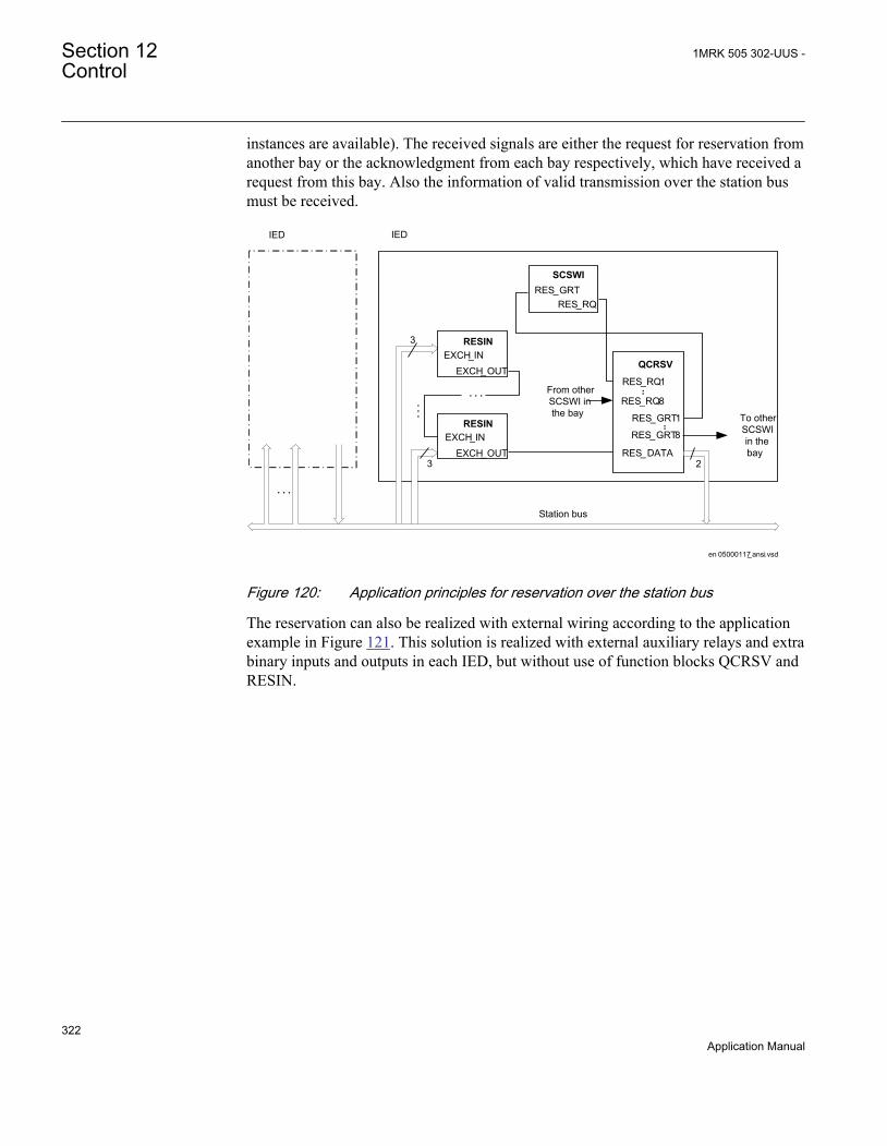
instances are available). The received signals are either the request for reservation fromanother bay or the acknowledgment from each bay respectively, which have received arequest from this bay. Also the information of valid transmission over the station busmust be received.
en 05000117_ansi.vsd
IEDIED
From other SCSWI in the bay To other
SCSWI in the bay
3
Station bus
. . .
. . .
. . .
3
RESIN
EXCH_OUTEXCH_IN
RESIN
EXCH_OUTEXCH_IN
..
SCSWI
RES_RQRES_GRT
RES_ DATA
QCRSV
RES_RQ1
RES_RQ8
RES_GRT1
RES_GRT8
..
2
ANSI05000117 V2 EN
Figure 120: Application principles for reservation over the station bus
The reservation can also be realized with external wiring according to the applicationexample in Figure 121. This solution is realized with external auxiliary relays and extrabinary inputs and outputs in each IED, but without use of function blocks QCRSV andRESIN.
Section 12 1MRK 505 302-UUS -Control
322Application Manual

en 05000118_ansi.vsd
SCSWI
SELECTEDRES_EXT
+
IED
BI BO
IED
BI BO
OROther SCSWI in the bay
ANSI05000118 V2 EN
Figure 121: Application principles for reservation with external wiring
The solution in Figure 121 can also be realized over the station bus according to theapplication example in Figure 122. The solutions in Figure 121 and Figure 122 do nothave the same high security compared to the solution in Figure 120, but instead have ahigher availability, since no acknowledgment is required.
SCSWI
SELECTED
RES_EXT
IEDIED
OROther SCWI inthe bay
Station bus. . .
SPGAPCIN
RESGRANT
IntlReceive
. . .
. . .
RESGRANT
IntlReceive
IEC05000178-3-en.vsd IEC05000178 V3 EN
Figure 122: Application principle for an alternative reservation solution
12.3.2 Interaction between modulesA typical bay with apparatus control function consists of a combination of logicalnodes or functions that are described here:
1MRK 505 302-UUS - Section 12Control
323Application Manual
• The Switch controller (SCSWI) initializes all operations for one apparatus. It is thecommand interface of the apparatus. It includes the position reporting as well asthe control of the position
• The Circuit breaker (SXCBR) is the process interface to the circuit breaker for theapparatus control function.
• The Circuit switch (SXSWI) is the process interface to the disconnector or thegrounding switch for the apparatus control function.
• The Bay control (QCBAY) fulfils the bay-level functions for the apparatuses, suchas operator place selection and blockings for the complete bay.
• The Reservation (QCRSV) deals with the reservation function.• The Protection trip logic (SMPPTRC, 94) connects the "trip" outputs of one or
more protection functions to a common "trip" to be transmitted to SXCBR.• The Autorecloser (SMBRREC, 79) consists of the facilities to automatically close
a tripped breaker with respect to a number of configurable conditions.• The logical node Interlocking (SCILO, 3) provides the information to SCSWI
whether it is permitted to operate due to the switchyard topology. The interlockingconditions are evaluated with separate logic and connected to SCILO (3).
• The Synchronism, energizing check, and synchronizing (SESRSYN, 25) calculatesand compares the voltage phasor difference from both sides of an open breakerwith predefined switching conditions (synchronism check). Also the case that oneside is dead (energizing-check) is included.
• The Generic Automatic Process Control function, GAPC, handles genericcommands from the operator to the system.
The overview of the interaction between these functions is shown in Figure 123 below.
Section 12 1MRK 505 302-UUS -Control
324Application Manual

ANSI05000120-2-en.vsd
ZMQPDIS(Distance)
SXCBR(Circuit breaker)
Interlockingfunctionblock
(Not a LN)
SCSWI(Switching control)
QCBAY(Bay control)
SMBRREC
(Auto-reclosure)
I/O
Trip
Close rel.
Res. req.
Initi
ate
AR
Close CB
Position
Res. granted
Operator placeselection
SCSWI(Switching control)
SXSWI(Disconnector)
Open cmd
Close cmd
Position
SECRSYN(Synchrocheck)
SCILO
SCILO
Synchrocheck OK
QCRSV(Reservation) Res. req.
Res. granted
GAPC(Generic
Automatic Process Control) Open/Close
Open/Close
Enable close
Enable open
Open rel.
Close rel.Open rel.
SMPPTRC(Trip logic)
Position
Ena
ble
open
Ena
ble
clos
e
Pos
. fro
m
othe
r bay
s
I/O
Open cmdClose cmd
(Interlocking)
(Interlocking)
ANSI05000120 V2 EN
Figure 123: Example overview of the interactions between functions in a typical bay
12.3.3 Setting guidelinesThe setting parameters for the apparatus control function are set via the local HMI orPCM600.
1MRK 505 302-UUS - Section 12Control
325Application Manual

12.3.3.1 Bay control (QCBAY)
If the parameter AllPSTOValid is set to No priority, all originators from local andremote are accepted without any priority.
If the parameter RemoteIncStation is set to Yes, commands from IEC61850-8-1 clientsat both station and remote level are accepted, when the QCBAY function is in Remote.If set to No, the command LocSta controls which operator place is accepted whenQCBAY is in Remote. If LocSta is true, only commands from station level areaccepted, otherwise only commands from remote level are accepted.
The parameter RemoteIncStation has only effect on the IEC61850-8-1communication. Further, when using IEC61850 edition 1communication, the parameter should be set to Yes, since the commandLocSta is not defined in IEC61850-8-1 edition 1.
12.3.3.2 Switch controller (SCSWI)
The parameter CtlModel specifies the type of control model according to IEC 61850.The default for control of circuit breakers, disconnectors and grounding switches thecontrol model is set to SBO Enh (Select-Before-Operate) with enhanced security.
When the operation shall be performed in one step, and no monitoring of the result ofthe command is desired, the model direct control with normal security is used.
At control with enhanced security there is an additional supervision of the status valueby the control object, which means that each command sequence must be terminatedby a termination command.
The parameter PosDependent gives permission to operate depending on the positionindication, that is, at Always permitted it is always permitted to operate independent ofthe value of the position. At Not perm at 00/11 it is not permitted to operate if theposition is in bad or intermediate state.
tSelect is the maximum allowed time between the select and the execute commandsignal, that is, the time the operator has to perform the command execution after theselection of the object to operate. When the time has expired, the selected output signalis set to false and a cause-code is given.
The time parameter tResResponse is the allowed time from reservation request to thefeedback reservation granted from all bays involved in the reservation function. Whenthe time has expired, the control function is reset, and a cause-code is given.
tSynchrocheck is the allowed time for the synchronism check function to fulfill theclose conditions. When the time has expired, the function tries to start the
Section 12 1MRK 505 302-UUS -Control
326Application Manual
synchronizing function. If tSynchrocheck is set to 0, no synchrocheck is done, beforestarting the synchronizing function.
The timer tSynchronizing supervises that the signal synchronizing in progress isobtained in SCSWI after start of the synchronizing function. The start signal for thesynchronizing is set if the synchronism check conditions are not fulfilled. When thetime has expired, the control function is reset, and a cause-code is given. If nosynchronizing function is included, the time is set to 0, which means no start of thesynchronizing function is done, and when tSynchrocheck has expired, the controlfunction is reset and a cause-code is given.
tExecutionFB is the maximum time between the execute command signal and thecommand termination. When the time has expired, the control function is reset and acause-code is given.
tPoleDiscord is the allowed time to have discrepancy between the poles at control ofthree single-phase breakers. At discrepancy an output signal is activated to be used fortrip or alarm, and during a command, the control function is reset, and a cause-code isgiven.
SuppressMidPos when On suppresses the mid-position during the time tIntermediateof the connected switches.
The parameter InterlockCheck decides if interlock check should be done at both selectand operate, Sel & Op phase, or only at operate, Op phase.
12.3.3.3 Switch (SXCBR/SXSWI)
tStartMove is the supervision time for the apparatus to start moving after a commandexecution. When the time has expired, the switch function is reset, and a cause-code isgiven.
During the tIntermediate time the position indication is allowed to be in anintermediate (00) state. When the time has expired, the switch function is reset, and acause-code is given. The indication of the mid-position at SCSWI is suppressed duringthis time period when the position changes from open to close or vice-versa if theparameter SuppressMidPos is set to On in the SCSWI function.
If the parameter AdaptivePulse is set to Adaptive the command output pulse resetswhen a new correct end position is reached. If the parameter is set to Not adaptive thecommand output pulse remains active until the timer tOpenPulsetClosePulse has elapsed.
tOpenPulse is the output pulse length for an open command. If AdaptivePulse is set toAdaptive, it is the maximum length of the output pulse for an open command. Thedefault length is set to 200 ms for a circuit breaker (SXCBR) and 500 ms for adisconnector (SXSWI).
1MRK 505 302-UUS - Section 12Control
327Application Manual
tClosePulse is the output pulse length for a close command. If AdaptivePulse is set toAdaptive, it is the maximum length of the output pulse for an open command. Thedefault length is set to 200 ms for a circuit breaker (SXCBR) and 500 ms for adisconnector (SXSWI).
12.3.3.4 Bay Reserve (QCRSV)
The timer tCancelRes defines the supervision time for canceling the reservation, whenthis cannot be done by requesting bay due to for example communication failure.
When the parameter ParamRequestx (x=1-8) is set to Only own bay res. individuallyfor each apparatus (x) in the bay, only the own bay is reserved, that is, the output forreservation request of other bays (RES_BAYS) will not be activated at selection ofapparatus x.
12.3.3.5 Reservation input (RESIN)
With the FutureUse parameter set to Bay future use the function can handle bays notyet installed in the SA system.
12.4 Logic rotating switch for function selection and LHMIpresentation SLGAPC
12.4.1 IdentificationFunction description IEC 61850
identificationIEC 60617identification
ANSI/IEEE C37.2device number
Logic rotating switch for functionselection and LHMI presentation
SLGAPC - -
12.4.2 ApplicationThe logic rotating switch for function selection and LHMI presentation function(SLGAPC) (or the selector switch function block, as it is also known) is used to get aselector switch functionality similar with the one provided by a hardware multi-position selector switch. Hardware selector switches are used extensively by utilities,in order to have different functions operating on pre-set values. Hardware switches arehowever sources for maintenance issues, lower system reliability and extendedpurchase portfolio. The virtual selector switches eliminate all these problems.
Section 12 1MRK 505 302-UUS -Control
328Application Manual

SLGAPC function block has two operating inputs (UP and DOWN), one blockinginput (BLOCK) and one operator position input (PSTO).
SLGAPC can be activated both from the local HMI and from external sources(switches), via the IED binary inputs. It also allows the operation from remote (like thestation computer). SWPOSN is an integer value output, giving the actual outputnumber. Since the number of positions of the switch can be established by settings (seebelow), one must be careful in coordinating the settings with the configuration (if onesets the number of positions to x in settings – for example, there will be only the first xoutputs available from the block in the configuration). Also the frequency of the (UP orDOWN) pulses should be lower than the setting tPulse.
From the local HMI, the selector switch can be operated from Single-line diagram (SLD).
12.4.3 Setting guidelinesThe following settings are available for the Logic rotating switch for function selectionand LHMI presentation (SLGAPC) function:
Operation: Sets the operation of the function Enabled or Disabled.
NrPos: Sets the number of positions in the switch (max. 32).
OutType: Steady or Pulsed.
tPulse: In case of a pulsed output, it gives the length of the pulse (in seconds).
tDelay: The delay between the UP or DOWN activation signal positive front and theoutput activation.
StopAtExtremes: Sets the behavior of the switch at the end positions – if set toDisabled, when pressing UP while on first position, the switch will jump to the lastposition; when pressing DOWN at the last position, the switch will jump to the firstposition; when set to Enabled, no jump will be allowed.
12.5 Selector mini switch VSGAPC
12.5.1 IdentificationFunction description IEC 61850
identificationIEC 60617identification
ANSI/IEEE C37.2device number
Selector mini switch VSGAPC - -
1MRK 505 302-UUS - Section 12Control
329Application Manual

12.5.2 ApplicationSelector mini switch (VSGAPC) function is a multipurpose function used in theconfiguration tool in PCM600 for a variety of applications, as a general purposeswitch. VSGAPC can be used for both acquiring an external switch position (throughthe IPOS1 and the IPOS2 inputs) and represent it through the single line diagramsymbols (or use it in the configuration through the outputs POS1 and POS2) as well as,a command function (controlled by the PSTO input), giving switching commandsthrough the CMDPOS12 and CMDPOS21 outputs.
The output POSITION is an integer output, showing the actual position as an integernumber 0 – 3.
An example where VSGAPC is configured to switch Autorecloser enabled–disabledfrom a button symbol on the local HMI is shown in figure 124. The Close and Openbuttons on the local HMI are normally used for enable–disable operations of the circuitbreaker.
ANSI07000112-3-en.vsd
PSTO
CMDPOS12
IPOS1
NAM_POS1NAM_POS2
IPOS2
CMDPOS21DisabledEnabled
VSGAPC
SMBRREC_79ONOFF
SETON
INTONE
INVOUT INPUT
ANSI07000112 V3 EN
Figure 124: Control of Autorecloser from local HMI through Selector mini switch
VSGAPC is also provided with IEC 61850 communication so it can be controlled fromSA system as well.
12.5.3 Setting guidelinesSelector mini switch (VSGAPC) function can generate pulsed or steady commands (bysetting the Mode parameter). When pulsed commands are generated, the length of thepulse can be set using the tPulse parameter. Also, being accessible on the single linediagram (SLD), this function block has two control modes (settable through CtlModel):Dir Norm and SBO Enh.
Section 12 1MRK 505 302-UUS -Control
330Application Manual

12.6 Generic communication function for Double Pointindication DPGAPC
12.6.1 IdentificationFunction description IEC 61850
identificationIEC 60617identification
ANSI/IEEE C37.2device number
Generic communication function forDouble Point indication
DPGAPC - -
12.6.2 ApplicationDPGAPC function block is used to combine three logical input signals into a two bitposition indication, and publish the position indication to other systems, equipment orfunctions in the substation. The three inputs are named OPEN, CLOSE and VALID.DPGAPC is intended to be used as a position indicator block in the interlockingstationwide logics.
The OPEN and CLOSE inputs set one bit each in the two bit position indication,POSITION. If both OPEN and CLOSE are set at the same time the quality of theoutput is set to invalid. The quality of the output is also set to invalid if the VALIDinput is not set.
12.6.3 Setting guidelinesThe function does not have any parameters available in the local HMI or PCM600.
12.7 Single point generic control 8 signals SPC8GAPC
12.7.1 IdentificationFunction description IEC 61850
identificationIEC 60617identification
ANSI/IEEE C37.2device number
Single point generic control 8 signals SPC8GAPC - -
1MRK 505 302-UUS - Section 12Control
331Application Manual

12.7.2 ApplicationThe Single point generic control 8 signals (SPC8GAPC) function block is a collectionof 8 single point commands, designed to bring in commands from REMOTE (SCADA)to those parts of the logic configuration that do not need complicated function blocksthat have the capability to receive commands (for example SCSWI). In this way,simple commands can be sent directly to the IED outputs, without confirmation.Confirmation (status) of the result of the commands is supposed to be achieved byother means, such as binary inputs and SPGGIO function blocks.
PSTO is the universal operator place selector for all control functions.Even if PSTO can be configured to allow LOCAL or ALL operatorpositions, the only functional position usable with the SPC8GAPCfunction block is REMOTE.
12.7.3 Setting guidelinesThe parameters for the single point generic control 8 signals (SPC8GAPC) function areset via the local HMI or PCM600.
Operation: turning the function operation Enabled/Disabled.
There are two settings for every command output (totally 8):
Latchedx: decides if the command signal for output x is Latched (steady) or Pulsed.
tPulsex: if Latchedx is set to Pulsed, then tPulsex will set the length of the pulse (inseconds).
12.8 AutomationBits, command function for DNP3.0AUTOBITS
12.8.1 IdentificationFunction description IEC 61850
identificationIEC 60617identification
ANSI/IEEE C37.2device number
AutomationBits, command function forDNP3 AUTOBITS - -
Section 12 1MRK 505 302-UUS -Control
332Application Manual

12.8.2 ApplicationAutomation bits, command function for DNP3 (AUTOBITS) is used within PCM600in order to get into the configuration the commands coming through the DNP3.0protocol.The AUTOBITS function plays the same role as functions GOOSEBINRCV(for IEC 61850) and MULTICMDRCV (for LON).AUTOBITS function block have 32individual outputs which each can be mapped as a Binary Output point in DNP3. Theoutput is operated by a "Object 12" in DNP3. This object contains parameters for control-code, count, on-time and off-time. To operate an AUTOBITS output point, send a control-code of latch-On, latch-Off, pulse-On, pulse-Off, Trip or Close. The remainingparameters are regarded as appropriate. For example, pulse-On, on-time=100, off-time=300, count=5 would give 5 positive 100 ms pulses, 300 ms apart.
For description of the DNP3 protocol implementation, refer to the Communicationmanual.
12.8.3 Setting guidelinesAUTOBITS function block has one setting, (Operation: Enabled/Disabled) enabling ordisabling the function. These names will be seen in the DNP3 communicationmanagement tool in PCM600.
12.9 Single command, 16 signals SINGLECMD
12.9.1 IdentificationFunction description IEC 61850
identificationIEC 60617identification
ANSI/IEEE C37.2device number
Single command, 16 signals SINGLECMD - -
12.9.2 ApplicationSingle command, 16 signals (SINGLECMD) is a common function and alwaysincluded in the IED.
The IEDs may be provided with a function to receive commands either from asubstation automation system or from the local HMI. That receiving function block hasoutputs that can be used, for example, to control high voltage apparatuses inswitchyards. For local control functions, the local HMI can also be used. Together with
1MRK 505 302-UUS - Section 12Control
333Application Manual

the configuration logic circuits, the user can govern pulses or steady output signals forcontrol purposes within the IED or via binary outputs.
Figure 125 shows an application example of how the user can connect SINGLECMDvia configuration logic circuit to control a high-voltage apparatus. This type ofcommand control is normally carried out by sending a pulse to the binary outputs ofthe IED. Figure 125 shows a close operation. An open breaker operation is performedin a similar way but without the synchro-check condition.
SinglecommandfunctionSINGLECMD
CMDOUTy
OUTy
Close CB1
ANDUser-definedconditionsSynchro-check
Configuration logic circuits
en04000206_ansi.vsdANSI04000206 V2 EN
Figure 125: Application example showing a logic diagram for control of a circuitbreaker via configuration logic circuits
Figure 126 and figure 127 show other ways to control functions, which require steadyEnabled/Disabled signals. Here, the output is used to control built-in functions orexternal devices.
Section 12 1MRK 505 302-UUS -Control
334Application Manual

SinglecommandfunctionSINGLECMD
CMDOUTy
OUTy
Function n
en04000207.vsd
Function n
IEC04000207 V2 EN
Figure 126: Application example showing a logic diagram for control of built-infunctions
Singlecommandfunction
SINGLESMD
CMDOUTy
OUTy
Device 1
User-definedconditions
Configuration logic circuits
en04000208_ansi.vsd
AND
ANSI04000208 V2 EN
Figure 127: Application example showing a logic diagram for control of externaldevices via configuration logic circuits
1MRK 505 302-UUS - Section 12Control
335Application Manual

12.9.3 Setting guidelinesThe parameters for Single command, 16 signals (SINGLECMD) are set via the localHMI or PCM600.
Parameters to be set are MODE, common for the whole block, and CMDOUTy whichincludes the user defined name for each output signal. The MODE input sets theoutputs to be one of the types Disabled, Steady, or Pulse.
• Disabled, sets all outputs to 0, independent of the values sent from the stationlevel, that is, the operator station or remote-control gateway.
• Steady, sets the outputs to a steady signal 0 or 1, depending on the values sentfrom the station level.
• Pulse, gives a pulse with 100 ms duration, if a value sent from the station level ischanged from 0 to 1. That means the configured logic connected to the commandfunction block may not have a cycle time longer than the cycle time for thecommand function block.
12.10 Interlocking (3)
The main purpose of switchgear interlocking is:
• To avoid the dangerous or damaging operation of switchgear• To enforce restrictions on the operation of the substation for other reasons for
example, load configuration. Examples of the latter are to limit the number ofparallel transformers to a maximum of two or to ensure that energizing is alwaysfrom one side, for example, the high voltage side of a transformer.
This section only deals with the first point, and only with restrictions caused byswitching devices other than the one to be controlled. This means that switch interlock,because of device alarms, is not included in this section.
Disconnectors and grounding switches have a limited switching capacity.Disconnectors may therefore only operate:
• With basically zero current. The circuit is open on one side and has a smallextension. The capacitive current is small (for example, < 5A) and powertransformers with inrush current are not allowed.
• To connect or disconnect a parallel circuit carrying load current. The switchingvoltage across the open contacts is thus virtually zero, thanks to the parallel circuit(for example, < 1% of rated voltage). Paralleling of power transformers is notallowed.
Section 12 1MRK 505 302-UUS -Control
336Application Manual

Grounding switches are allowed to connect and disconnect grounding of isolatedpoints. Due to capacitive or inductive coupling there may be some voltage (forexample < 40% of rated voltage) before grounding and some current (for example <100A) after grounding of a line.
Circuit breakers are usually not interlocked. Closing is only interlocked againstrunning disconnectors in the same bay, and the bus-coupler opening is interlockedduring a busbar transfer.
The positions of all switching devices in a bay and from some other bays determine theconditions for operational interlocking. Conditions from other stations are usually notavailable. Therefore, a line grounding switch is usually not fully interlocked. Theoperator must be convinced that the line is not energized from the other side beforeclosing the grounding switch. As an option, a voltage indication can be used forinterlocking. Take care to avoid a dangerous enable condition at the loss of a VTsecondary voltage, for example, because of a blown fuse.
The switch positions used by the operational interlocking logic are obtained fromauxiliary contacts or position sensors. For each end position (open or closed) a trueindication is needed - thus forming a double indication. The apparatus control functioncontinuously checks its consistency. If neither condition is high (1 or TRUE), theswitch may be in an intermediate position, for example, moving. This dynamic statemay continue for some time, which in the case of disconnectors may be up to 10seconds. Should both indications stay low for a longer period, the position indicationwill be interpreted as unknown. If both indications stay high, something is wrong, andthe state is again treated as unknown.
In both cases an alarm is sent to the operator. Indications from position sensors shall beself-checked and system faults indicated by a fault signal. In the interlocking logic, thesignals are used to avoid dangerous enable or release conditions. When the switchingstate of a switching device cannot be determined operation is not permitted.
For switches with an individual operation gear per phase, the evaluation must considerpossible phase discrepancies. This is done with the aid of an AND-function for all threephases in each apparatus for both open and close indications. Phase discrepancies willresult in an unknown double indication state.
12.10.1 Configuration guidelinesThe following sections describe how the interlocking for a certain switchgearconfiguration can be realized in the IED by using standard interlocking modules andtheir interconnections. They also describe the configuration settings. The inputs fordelivery specific conditions (Qx_EXy) are set to 1=TRUE if they are not used, exceptin the following cases:
1MRK 505 302-UUS - Section 12Control
337Application Manual

• 989_EX2 and 989_EX4 in modules BH_LINE_A and BH_LINE_B• 152_EX3 in module AB_TRAFO
when they are set to 0=FALSE.
12.10.2 Interlocking for line bay ABC_LINE (3)
12.10.2.1 Application
The interlocking for line bay (ABC_LINE, 3) function is used for a line connected to adouble busbar arrangement with a transfer busbar according to figure 128. Thefunction can also be used for a double busbar arrangement without transfer busbar or asingle busbar arrangement with/without transfer busbar.
189 289189G
289G
989989G
WA1 (A)
WA2 (B)
WA7 (C)
789
en04000478_ansi.vsd
152
ANSI04000478 V1 EN
Figure 128: Switchyard layout ABC_LINE (3)
The signals from other bays connected to the module ABC_LINE (3) are described below.
12.10.2.2 Signals from bypass busbar
To derive the signals:
Signal BB7_D_OP All line disconnectors on bypass WA7 except in the own bay are open.
VP_BB7_D The switch status of disconnectors on bypass busbar WA7 are valid.
EXDU_BPB No transmission error from any bay containing disconnectors on bypass busbar WA7
Section 12 1MRK 505 302-UUS -Control
338Application Manual

These signals from each line bay (ABC_LINE, 3) except that of the own bay are needed:
Signal 789OPTR 789 is open
VP789TR The switch status for 789 is valid.
EXDU_BPB No transmission error from the bay that contains the above information.
For bay n, these conditions are valid:
AND BB7_D_OP
VP_BB7_D
EXDU_BPB
en04000477_ansi.vsd
AND
AND
789OPTR (bay 1)789OPTR (bay 2)
. . .
. . .789OPTR (bay n-1)
VP789TR (bay 1)VP789TR (bay 2)
. . .
. . .VP789TR (bay n-1)
EXDU_BPB (bay 1)EXDU_BPB (bay 2)
. . .
. . .EXDU_BPB (bay n-1)
ANSI04000477 V1 EN
Figure 129: Signals from bypass busbar in line bay n
12.10.2.3 Signals from bus-coupler
If the busbar is divided by bus-section disconnectors into bus sections, the busbar-busbar connection could exist via the bus-section disconnector and bus-coupler withinthe other bus section.
1MRK 505 302-UUS - Section 12Control
339Application Manual

Section 1 Section 2
A1A2_DC(BS)B1B2_DC(BS)
ABC_LINE ABC_BCABC_LINE ABC_BC
(WA1)A1
(WA2)B1
(WA7)C C
B2
A2
en04000479_ansi.vsdANSI04000479 V1 EN
Figure 130: Busbars divided by bus-section disconnectors (circuit breakers)
To derive the signals:
Signal BC_12_CL A bus-coupler connection exists between busbar WA1 and WA2.
BC_17_OP No bus-coupler connection between busbar WA1 and WA7.
BC_17_CL A bus-coupler connection exists between busbar WA1and WA7.
BC_27_OP No bus-coupler connection between busbar WA2 and WA7.
BC_27_CL A bus-coupler connection exists between busbar WA2 and WA7.
VP_BC_12 The switch status of BC_12 is valid.
VP_BC_17 The switch status of BC_17 is valid.
VP_BC_27 The switch status of BC_27 is valid.
EXDU_BC No transmission error from any bus-coupler bay (BC).
These signals from each bus-coupler bay (ABC_BC) are needed:
Signal BC12CLTR A bus-coupler connection through the own bus-coupler exists between busbar WA1
and WA2.
BC17OPTR No bus-coupler connection through the own bus-coupler between busbar WA1 andWA7.
BC17CLTR A bus-coupler connection through the own bus-coupler exists between busbar WA1and WA7.
BC27OPTR No bus-coupler connection through the own bus-coupler between busbar WA2 andWA7.
BC27CLTR A bus-coupler connection through the own bus-coupler exists between busbar WA2and WA7.
VPBC12TR The switch status of BC_12 is valid.
VPBC17TR The switch status of BC_17 is valid.
VPBC27TR The switch status of BC_27 is valid.
EXDU_BC No transmission error from the bay that contains the above information.
Section 12 1MRK 505 302-UUS -Control
340Application Manual

These signals from each bus-section disconnector bay (A1A2_DC) are also needed.For B1B2_DC, corresponding signals from busbar B are used. The same type ofmodule (A1A2_DC) is used for different busbars, that is, for both bus-sectiondisconnector A1A2_DC and B1B2_DC.
Signal DCOPTR The bus-section disconnector is open.
DCCLTR The bus-section disconnector is closed.
VPDCTR The switch status of bus-section disconnector DC is valid.
EXDU_DC No transmission error from the bay that contains the above information.
If the busbar is divided by bus-section circuit breakers, the signals from the bus-sectioncoupler bay (A1A2_BS), rather than the bus-section disconnector bay (A1A2_DC)must be used. For B1B2_BS, corresponding signals from busbar B are used. The sametype of module (A1A2_BS) is used for different busbars, that is, for both bus-sectioncircuit breakers A1A2_BS and B1B2_BS.
Signal S1S2OPTR No bus-section coupler connection between bus-sections 1 and 2.
S1S2CLTR A bus-section coupler connection exists between bus-sections 1 and 2.
VPS1S2TR The switch status of bus-section coupler BS is valid.
EXDU_BS No transmission error from the bay that contains the above information.
For a line bay in section 1, these conditions are valid:
1MRK 505 302-UUS - Section 12Control
341Application Manual

BC12CLTR (sect.1)
DCCLTR (A1A2)DCCLTR (B1B2)
ORAND
BC12CLTR (sect.2)
VPBC12TR (sect.1)VPDCTR (A1A2)VPDCTR (B1B2)
VPBC12TR (sect.2)
OR
BC17OPTR (sect.1)
DCOPTR (A1A2)BC17OPTR (sect.2)
BC17CLTR (sect.1)
DCCLTR (A1A2)BC17CLTR (sect.2)
VPBC17TR (sect.1)VPDCTR (A1A2)
VPBC17TR (sect.2)
BC27OPTR (sect.1)
DCOPTR (B1B2)BC27OPTR (sect.2)
BC27CLTR (sect.1)
DCCLTR (B1B2)BC27CLTR (sect.2)
VPBC27TR (sect.1)VPDCTR (B1B2)
VPBC27TR (sect.2)
EXDU_BC (sect.1)EXDU_DC (A1A2)EXDU_DC (B1B2)EXDU_BC (sect.2)
BC_12_CL
VP_BC_12
BC_17_OP
BC_17_CL
VP_BC_17
BC_27_OP
BC_27_CL
VP_BC_27
EXDU_BC
en04000480_ansi.vsd
AND
AND
ANDOR
AND
ANDOR
ANDOR
AND
AND
ANSI04000480 V1 EN
Figure 131: Signals to a line bay in section 1 from the bus-coupler bays in eachsection
For a line bay in section 2, the same conditions as above are valid by changing section1 to section 2 and vice versa.
Section 12 1MRK 505 302-UUS -Control
342Application Manual
12.10.2.4 Configuration setting
If there is no bypass busbar and therefore no 789 disconnector, then the interlockingfor 789 is not used. The states for 789, 7189G, BB7_D, BC_17, BC_27 are set to openby setting the appropriate module inputs as follows. In the functional block diagram, 0and 1 are designated 0=FALSE and 1=TRUE:
• 789_OP = 1• 789_CL = 0
• 7189G_OP = 1• 7189G_CL = 0
• BB7_D_OP = 1
• BC_17_OP = 1• BC_17_CL = 0• BC_27_OP = 1• BC_27_CL = 0
• EXDU_BPB = 1
• VP_BB7_D = 1• VP_BC_17 = 1• VP_BC_27 = 1
If there is no second busbar WA2 and therefore no 289 disconnector, then theinterlocking for 289 is not used. The state for 289, 2189G, BC_12, BC_27 are set toopen by setting the appropriate module inputs as follows. In the functional blockdiagram, 0 and 1 are designated 0=FALSE and 1=TRUE:
• 289_OP = 1• 289_CL = 0
• 2189G_OP = 1• 2189G_CL = 0
• BC_12_CL = 0• BC_27_OP = 1• BC_27_CL = 0
• VP_BC_12 = 1
1MRK 505 302-UUS - Section 12Control
343Application Manual

12.10.3 Interlocking for bus-coupler bay ABC_BC (3)
12.10.3.1 Application
The interlocking for bus-coupler bay (ABC_BC, 3) function is used for a bus-couplerbay connected to a double busbar arrangement according to figure 132. The functioncan also be used for a single busbar arrangement with transfer busbar or double busbararrangement without transfer busbar.
189 289 189G
WA1 (A)
WA2 (B)
WA7 (C)
7892089
289G
en04000514_ansi.vsd
152
ANSI04000514 V1 EN
Figure 132: Switchyard layout ABC_BC (3)
12.10.3.2 Configuration
The signals from the other bays connected to the bus-coupler module ABC_BC aredescribed below.
12.10.3.3 Signals from all feeders
To derive the signals:
Signal BBTR_OP No busbar transfer is in progress concerning this bus-coupler.
VP_BBTR The switch status is valid for all apparatuses involved in the busbar transfer.
EXDU_12 No transmission error from any bay connected to the WA1/WA2 busbars.
These signals from each line bay (ABC_LINE), each transformer bay (AB_TRAFO),and bus-coupler bay (ABC_BC), except the own bus-coupler bay are needed:
Section 12 1MRK 505 302-UUS -Control
344Application Manual

Signal Q1289OPTR 189 or 289 or both are open.
VP1289TR The switch status of 189 and 289 are valid.
EXDU_12 No transmission error from the bay that contains the above information.
For bus-coupler bay n, these conditions are valid:
1289OPTR (bay 1)1289OPTR (bay 2)
. . .
. . .1289OPTR (bay n-1)
AND BBTR_OP
VP1289TR (bay 1)VP1289TR (bay 2)
. . .
. . .VP1289TR (bay n-1)
AND VP_BBTR
EXDU_12 (bay 1)EXDU_12 (bay 2)
. . .
. . .EXDU_12 (bay n-1)
AND EXDU_12
en04000481_ansi.vsdANSI04000481 V1 EN
Figure 133: Signals from any bays in bus-coupler bay n
If the busbar is divided by bus-section disconnectors into bus-sections, the signalsBBTR are connected in parallel - if both bus-section disconnectors are closed. So forthe basic project-specific logic for BBTR above, add this logic:
Section 1 Section 2
A1A2_DC(BS)B1B2_DC(BS)
ABC_LINE
ABC_BC
ABC_LINE ABC_BC
(WA1)A1
(WA2)B1
(WA7)C C
B2
A2
en04000482_ansi.vsd
AB_TRAFO
ANSI04000482 V1 EN
Figure 134: Busbars divided by bus-section disconnectors (circuit breakers)
1MRK 505 302-UUS - Section 12Control
345Application Manual

The following signals from each bus-section disconnector bay (A1A2_DC) are needed.For B1B2_DC, corresponding signals from busbar B are used. The same type ofmodule (A1A2_DC) is used for different busbars, that is, for both bus-sectiondisconnector A1A2_DC and B1B2_DC.
Signal DCOPTR The bus-section disconnector is open.
VPDCTR The switch status of bus-section disconnector DC is valid.
EXDU_DC No transmission error from the bay that contains the above information.
If the busbar is divided by bus-section circuit breakers, the signals from the bus-sectioncoupler bay (A1A2_BS), rather than the bus-section disconnector bay (A1A2_DC),have to be used. For B1B2_BS, corresponding signals from busbar B are used. Thesame type of module (A1A2_BS) is used for different busbars, that is, for both bus-section circuit breakers A1A2_BS and B1B2_BS.
Signal S1S2OPTR No bus-section coupler connection between bus-sections 1 and 2.
VPS1S2TR The switch status of bus-section coupler BS is valid.
EXDU_BS No transmission error from the bay that contains the above information.
For a bus-coupler bay in section 1, these conditions are valid:
en04000483_ansi.vsd
ANDVP_BBTR
EXDU_12AND
BBTR_OP
ORAND
BBTR_OP (sect.1)
DCOPTR (A1A2)DCOPTR (B1B2)
BBTR_OP (sect.2)
VP_BBTR (sect.1)VPDCTR (A1A2)VPDCTR (B1B2)
VP_BBTR (sect.2)
EXDU_12 (sect.1)
EXDU_DC (B1B2)EXDU_12 (sect.2)
EXDU_DC (A1A2)
ANSI04000483 V1 EN
Figure 135: Signals to a bus-coupler bay in section 1 from any bays in each section
Section 12 1MRK 505 302-UUS -Control
346Application Manual

For a bus-coupler bay in section 2, the same conditions as above are valid by changingsection 1 to section 2 and vice versa.
12.10.3.4 Signals from bus-coupler
If the busbar is divided by bus-section disconnectors into bus-sections, the signalsBC_12 from the busbar coupler of the other busbar section must be transmitted to theown busbar coupler if both disconnectors are closed.
en04000484_ansi.vsd
Section 1 Section 2
A1A2_DC(BS)B1B2_DC(BS)
ABC_BCABC_BC
(WA1)A1(WA2)B1(WA7)C C
B2A2
ANSI04000484 V1 EN
Figure 136: Busbars divided by bus-section disconnectors (circuit breakers)
To derive the signals:
Signal BC_12_CL Another bus-coupler connection exists between busbar WA1 and WA2.
VP_BC_12 The switch status of BC_12 is valid.
EXDU_BC No transmission error from any bus-coupler bay (BC).
These signals from each bus-coupler bay (ABC_BC), except the own bay, are needed:
Signal BC12CLTR A bus-coupler connection through the own bus-coupler exists between busbar WA1
and WA2.
VPBC12TR The switch status of BC_12 is valid.
EXDU_BC No transmission error from the bay that contains the above information.
These signals from each bus-section disconnector bay (A1A2_DC) are also needed.For B1B2_DC, corresponding signals from busbar B are used. The same type ofmodule (A1A2_DC) is used for different busbars, that is, for both bus-sectiondisconnector A1A2_DC and B1B2_DC.
1MRK 505 302-UUS - Section 12Control
347Application Manual

Signal DCCLTR The bus-section disconnector is closed.
VPDCTR The switch status of bus-section disconnector DC is valid.
EXDU_DC No transmission error from the bay that contains the above information.
If the busbar is divided by bus-section circuit breakers, the signals from the bus-sectioncoupler bay (A1A2_BS), rather than the bus-section disconnector bay (A1A2_DC),must be used. For B1B2_BS, corresponding signals from busbar B are used. The sametype of module (A1A2_BS) is used for different busbars, that is, for both bus-sectioncircuit breakers A1A2_BS and B1B2_BS.
Signal S1S2CLTR A bus-section coupler connection exists between bus sections 1 and 2.
VPS1S2TR The switch status of bus-section coupler BS is valid.
EXDU_BS No transmission error from the bay containing the above information.
For a bus-coupler bay in section 1, these conditions are valid:
AND BC_12_CL
VP_BC_12
EXDU_BC
en04000485_ansi.vsd
AND
AND
DCCLTR (A1A2)DCCLTR (B1B2)
BC12CLTR (sect.2)
VPDCTR (A1A2)VPDCTR (B1B2)
VPBC12TR (sect.2)
EXDU_DC (A1A2)EXDU_DC (B1B2)EXDU_BC (sect.2)
ANSI04000485 V1 EN
Figure 137: Signals to a bus-coupler bay in section 1 from a bus-coupler bay inanother section
For a bus-coupler bay in section 2, the same conditions as above are valid by changingsection 1 to section 2 and vice versa.
12.10.3.5 Configuration setting
If there is no bypass busbar and therefore no 289 and 789 disconnectors, then theinterlocking for 289 and 789 is not used. The states for 289, 789, 7189G are set to open
Section 12 1MRK 505 302-UUS -Control
348Application Manual
by setting the appropriate module inputs as follows. In the functional block diagram, 0and 1 are designated 0=FALSE and 1=TRUE:
• 289_OP = 1• 289_CL = 0
• 789_OP = 1• 789_CL = 0
• 7189G_OP = 1• 7189G_CL = 0
If there is no second busbar B and therefore no 289 and 2089 disconnectors, then theinterlocking for 289 and 2089 are not used. The states for 289, 2089, 2189G, BC_12,BBTR are set to open by setting the appropriate module inputs as follows. In thefunctional block diagram, 0 and 1 are designated 0=FALSE and 1=TRUE:
• 289_OP = 1• 289_CL = 0
• 2089_OP = 1• 2089_CL = 0
• 2189G_OP = 1• 2189G_CL = 0
• BC_12_CL = 0• VP_BC_12 = 1
• BBTR_OP = 1• VP_BBTR = 1
12.10.4 Interlocking for transformer bay AB_TRAFO (3)
12.10.4.1 Application
The interlocking for transformer bay (AB_TRAFO, 3) function is used for atransformer bay connected to a double busbar arrangement according to figure 138.The function is used when there is no disconnector between circuit breaker andtransformer. Otherwise, the interlocking for line bay (ABC_LINE, 3) function can beused. This function can also be used in single busbar arrangements.
1MRK 505 302-UUS - Section 12Control
349Application Manual

189 289189G
289G
WA1 (A)
WA2 (B)
389G
489G
489389
252 and 489G are not used in this interlocking
AB_TRAFO
en04000515_ansi.vsd
252
152
ANSI04000515 V1 EN
Figure 138: Switchyard layout AB_TRAFO (3)
The signals from other bays connected to the module AB_TRAFO are described below.
12.10.4.2 Signals from bus-coupler
If the busbar is divided by bus-section disconnectors into bus-sections, the busbar-busbar connection could exist via the bus-section disconnector and bus-coupler withinthe other bus-section.
Section 12 1MRK 505 302-UUS -Control
350Application Manual

en04000487_ansi.vsd
Section 1 Section 2
A1A2_DC(BS)B1B2_DC(BS)
AB_TRAFO ABC_BCAB_TRAFO ABC_BC
(WA1)A1(WA2)B1(WA7)C C
B2A2
ANSI04000487 V1 EN
Figure 139: Busbars divided by bus-section disconnectors (circuit breakers)
The project-specific logic for input signals concerning bus-coupler are the same as thespecific logic for the line bay (ABC_LINE):
Signal BC_12_CL A bus-coupler connection exists between busbar WA1 and WA2.
VP_BC_12 The switch status of BC_12 is valid.
EXDU_BC No transmission error from bus-coupler bay (BC).
The logic is identical to the double busbar configuration “Signals from bus-coupler“.
12.10.4.3 Configuration setting
If there are no second busbar B and therefore no 289 disconnector, then theinterlocking for 289 is not used. The state for 289, 2189G, BC_12 are set to open bysetting the appropriate module inputs as follows. In the functional block diagram, 0 and1 are designated 0=FALSE and 1=TRUE:
• 289_OP = 1• 289QB2_CL = 0
• 2189G_OP = 1• 2189G_CL = 0
• BC_12_CL = 0• VP_BC_12 = 1
1MRK 505 302-UUS - Section 12Control
351Application Manual
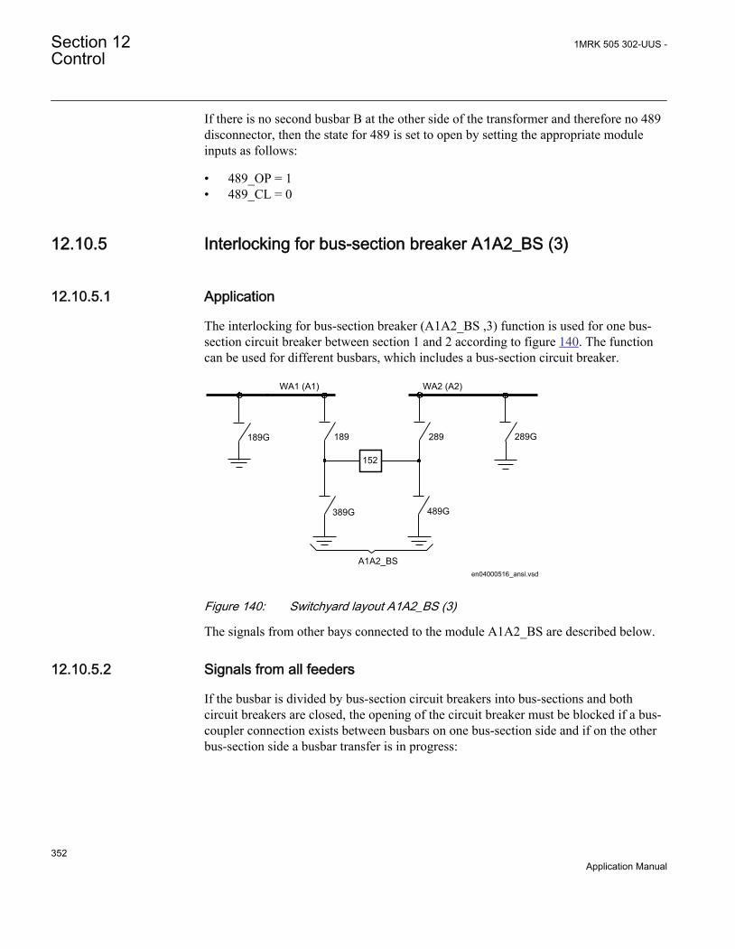
If there is no second busbar B at the other side of the transformer and therefore no 489disconnector, then the state for 489 is set to open by setting the appropriate moduleinputs as follows:
• 489_OP = 1• 489_CL = 0
12.10.5 Interlocking for bus-section breaker A1A2_BS (3)
12.10.5.1 Application
The interlocking for bus-section breaker (A1A2_BS ,3) function is used for one bus-section circuit breaker between section 1 and 2 according to figure 140. The functioncan be used for different busbars, which includes a bus-section circuit breaker.
WA1 (A1)
289
489G
189
389G
WA2 (A2)
en04000516_ansi.vsd
289G189G
A1A2_BS
152
ANSI04000516 V1 EN
Figure 140: Switchyard layout A1A2_BS (3)
The signals from other bays connected to the module A1A2_BS are described below.
12.10.5.2 Signals from all feeders
If the busbar is divided by bus-section circuit breakers into bus-sections and bothcircuit breakers are closed, the opening of the circuit breaker must be blocked if a bus-coupler connection exists between busbars on one bus-section side and if on the otherbus-section side a busbar transfer is in progress:
Section 12 1MRK 505 302-UUS -Control
352Application Manual

en04000489_ansi.vsd
Section 1 Section 2
A1A2_BSB1B2_BS
ABC_LINE
ABC_BC
ABC_LINE
ABC_BC
(WA1)A1(WA2)B1(WA7)C C
B2A2
AB_TRAFOAB_TRAFO
ANSI04000489 V1 EN
Figure 141: Busbars divided by bus-section circuit breakers
To derive the signals:
Signal BBTR_OP No busbar transfer is in progress concerning this bus-section.
VP_BBTR The switch status of BBTR is valid.
EXDU_12 No transmission error from any bay connected to busbar 1(A) and 2(B).
These signals from each line bay (ABC_LINE), each transformer bay (AB_TRAFO),and bus-coupler bay (ABC_BC) are needed:
Signal 1289OPTR 189 or 289 or both are open.
VP1289TR The switch status of 189 and 289 are valid.
EXDU_12 No transmission error from the bay that contains the above information.
These signals from each bus-coupler bay (ABC_BC) are needed:
Signal BC12OPTR No bus-coupler connection through the own bus-coupler between busbar WA1 and
WA2.
VPBC12TR The switch status of BC_12 is valid.
EXDU_BC No transmission error from the bay that contains the above information.
These signals from the bus-section circuit breaker bay (A1A2_BS, B1B2_BS) are needed.
Signal S1S2OPTR No bus-section coupler connection between bus-sections 1 and 2.
VPS1S2TR The switch status of bus-section coupler BS is valid.
EXDU_BS No transmission error from the bay that contains the above information.
1MRK 505 302-UUS - Section 12Control
353Application Manual

For a bus-section circuit breaker between A1 and A2 section busbars, these conditionsare valid:
en04000490_ansi.vsd
S1S2OPTR (B1B2)BC12OPTR (sect.1)
1289OPTR (bay 1/sect.2)
1289OPTR (bay n/sect.2)
S1S2OPTR (B1B2)BC12OPTR (sect.2)
1289OPTR (bay 1/sect.1)
1289OPTR (bay n /sect.1)
BBTR_OP
VP_BBTR
EXDU_12
OR
AND
OR
AND
. . .
. . .
. . .
. . .
AND
AND
VPS1S2TR (B1B2)VPBC12TR (sect.1)
VP1289TR (bay 1/sect.2)
VP1289TR (bay n/sect.1). . .. . .
VPBC12TR (sect.2)VP1289TR (bay 1/sect.1)
VP1289TR (bay n/sect.1)
. . .
. . .
AND
EXDU_12 (bay 1/sect.2)
EXDU_12 (bay n /sect.2)
EXDU_12(bay 1/sect.1)
EXDU_12 (bay n /sect.1)
EXDU_BS (B1B2)EXDU_BC (sect.1)
EXDU_BC (sect.2)
. . .
. . .
. . .
. . .
ANSI04000490 V1 EN
Figure 142: Signals from any bays for a bus-section circuit breaker betweensections A1 and A2
For a bus-section circuit breaker between B1 and B2 section busbars, these conditionsare valid:
Section 12 1MRK 505 302-UUS -Control
354Application Manual

en04000491_ansi.vsd
S1S2OPTR (A1A2)BC12OPTR (sect.1)
1289OPTR (bay 1/sect.2)
1289OPTR (bay n/sect.2)
S1S2OPTR (A1A2)BC12OPTR (sect.2)
1289OPTR (bay 1/sect.1)
1289OPTR (bay n /sect.1)
BBTR_OP
VP_BBTR
EXDU_12
ORAND
ORAND
. . .
. . .
. . .
. . .
AND
AND
VPS1S2TR (A1A2)VPBC12TR (sect.1)
VP1289TR (bay 1/sect.2)
VP1289TR (bay n/sect.1). . .. . .
VPBC12TR (sect.2)VP1289TR (bay 1/sect.1)
VP1289TR (bay n/sect.1)
. . .
. . .
AND
EXDU_12(bay 1/sect.2)
EXDU_12 (bay n /sect.2)
EXDU_12 (bay 1/sect.1)
EXDU_12 (bay n /sect.1)
EXDU_BS (A1A2)EXDU_BC (sect.1)
EXDU_BC (sect.2)
. . .
. . .
. . .
. . .
ANSI04000491 V1 EN
Figure 143: Signals from any bays for a bus-section circuit breaker betweensections B1 and B2
12.10.5.3 Configuration setting
If there is no other busbar via the busbar loops that are possible, then either theinterlocking for the 152 open circuit breaker is not used or the state for BBTR is set toopen. That is, no busbar transfer is in progress in this bus-section:
• BBTR_OP = 1• VP_BBTR = 1
1MRK 505 302-UUS - Section 12Control
355Application Manual

12.10.6 Interlocking for bus-section disconnector A1A2_DC (3)
12.10.6.1 Application
The interlocking for bus-section disconnector (A1A2_DC, 3) function is used for onebus-section disconnector between section 1 and 2 according to figure 144. A1A2_DC (3)function can be used for different busbars, which includes a bus-section disconnector.
WA1 (A1) WA2 (A2)
189G 289G
A1A2_DC en04000492_ansi.vsd
52
ANSI04000492 V1 EN
Figure 144: Switchyard layout A1A2_DC (3)
The signals from other bays connected to the module A1A2_DC are described below.
12.10.6.2 Signals in single breaker arrangement
If the busbar is divided by bus-section disconnectors, the condition no otherdisconnector connected to the bus-section must be made by a project-specific logic.
The same type of module (A1A2_DC) is used for different busbars, that is, for both bus-section disconnector A1A2_DC and B1B2_DC. But for B1B2_DC, correspondingsignals from busbar B are used.
en04000493_ansi.vsd
Section 1 Section 2
A1A2_DC(BS)B1B2_DC(BS)
ABC_LINEABC_BC
ABC_LINE
(WA1)A1(WA2)B1(WA7)C C
B3A3
AB_TRAFOAB_TRAFO
A2B2
ANSI04000493 V1 EN
Figure 145: Busbars divided by bus-section disconnectors (circuit breakers)
To derive the signals:
Section 12 1MRK 505 302-UUS -Control
356Application Manual

Signal S1DC_OP All disconnectors on bus-section 1 are open.
S2DC_OP All disconnectors on bus-section 2 are open.
VPS1_DC The switch status of disconnectors on bus-section 1 is valid.
VPS2_DC The switch status of disconnectors on bus-section 2 is valid.
EXDU_BB No transmission error from any bay that contains the above information.
These signals from each line bay (ABC_LINE), each transformer bay (AB_TRAFO),and each bus-coupler bay (ABC_BC) are needed:
Signal 189OPTR 189 is open.
289OPTR 289 is open (AB_TRAFO, ABC_LINE).
22089OTR 289 and 2089 are open (ABC_BC).
VP189TR The switch status of 189 is valid.
VP289TR The switch status of 289 is valid.
V22089TR The switch status of 289 and 2089 are valid.
EXDU_BB No transmission error from the bay that contains the above information.
If there is an additional bus-section disconnector, the signal from the bus-sectiondisconnector bay (A1A2_DC) must be used:
Signal DCOPTR The bus-section disconnector is open.
VPDCTR The switch status of bus-section disconnector DC is valid.
EXDU_DC No transmission error from the bay that contains the above information.
If there is an additional bus-section circuit breaker rather than an additional bus-sectiondisconnector the signals from the bus-section, circuit-breaker bay (A1A2_BS) ratherthan the bus-section disconnector bay (A1A2_DC) must be used:
Signal 189OPTR 189 is open.
289OPTR 289 is open.
VP189TR The switch status of 189 is valid.
VP289TR The switch status of 289 is valid.
EXDU_BS No transmission error from the bay BS (bus-section coupler bay) that contains theabove information.
1MRK 505 302-UUS - Section 12Control
357Application Manual

For a bus-section disconnector, these conditions from the A1 busbar section are valid:
189OPTR (bay 1/sect.A1) S1DC_OP
VPS1_DC
EXDU_BB
en04000494_ansi.vsd
AND
189OPTR (bay n/sect.A1)
. . .
. . .
. . .
VP189TR (bay 1/sect.A1)
VP189TR (bay n/sect.A1)
EXDU_BB (bay 1/sect.A1)
EXDU_BB (bay n/sect.A1)
. . .
. . .
. . .
. . .
. . .
. . .AND
AND
ANSI04000494 V1 EN
Figure 146: Signals from any bays in section A1 to a bus-section disconnector
For a bus-section disconnector, these conditions from the A2 busbar section are valid:
en04000495_ansi.vsd
189OPTR (bay 1/sect.A2) S2DC_OP
VPS2_DC
EXDU_BB
189OPTR (bay n/sect.A2)
. . .
. . .
. . .
VP189TR (bay 1/sect.A2)
VP189TR (bay n/sect.A2)VPDCTR (A2/A3)
EXDU_BB (bay n/sect.A2)
. . .
. . .
. . .
. . .
. . .
. . .
AND
DCOPTR (A2/A3)
EXDU_BB (bay 1/sect.A2)
EXDU_DC (A2/A3)
AND
AND
ANSI04000495 V1 EN
Figure 147: Signals from any bays in section A2 to a bus-section disconnector
For a bus-section disconnector, these conditions from the B1 busbar section are valid:
Section 12 1MRK 505 302-UUS -Control
358Application Manual

en04000496_ansi.vsd
289OPTR (22089OTR)(bay 1/sect.B1) S1DC_OP
VPS1_DC
EXDU_BB
289OPTR (22089OTR)(bay n/sect.B1)
. . .
. . .
. . .
VP289TR (V22089TR)(bay 1/sect.B1)
VP289TR (V22089TR)(bay n/sect.B1)
EXDU_BB (bay 1/sect.B1)
EXDU_BB (bay n/sect.B1)
. . .
. . .
. . .
. . .
. . .
. . .
AND
AND
AND
ANSI04000496 V1 EN
Figure 148: Signals from any bays in section B1 to a bus-section disconnector
For a bus-section disconnector, these conditions from the B2 busbar section are valid:
en04000497_ansi.vsd
289OPTR (22089OTR)(bay 1/sect.B2) S2DC_OP
VPS2_DC
EXDU_BB
289OPTR (22089OTR)(bay n/sect.B2)
. . .
. . .
. . .
VP289TR(V22089TR) (bay 1/sect.B2)
VP289TR(V22089TR) (bay n/sect.B2)VPDCTR (B2/B3)
EXDU_BB (bay n/sect.B2)
. . .
. . .
. . .
. . .
. . .
. . .
AND
DCOPTR (B2/B3)
EXDU_BB (bay 1/sect.B2)
EXDU_DC (B2/B3)
AND
AND
ANSI04000497 V1 EN
Figure 149: Signals from any bays in section B2 to a bus-section disconnector
12.10.6.3 Signals in double-breaker arrangement
If the busbar is divided by bus-section disconnectors, the condition for the busbardisconnector bay no other disconnector connected to the bus-section must be made bya project-specific logic.
1MRK 505 302-UUS - Section 12Control
359Application Manual

The same type of module (A1A2_DC) is used for different busbars, that is, for both bus-section disconnector A1A2_DC and B1B2_DC. But for B1B2_DC, correspondingsignals from busbar B are used.
en04000498_ansi.vsd
Section 1 Section 2
A1A2_DC(BS)B1B2_DC(BS)
DB_BUS DB_BUSDB_BUS DB_BUS
(WA1)A1(WA2)B1 B2
A2
ANSI04000498 V1 EN
Figure 150: Busbars divided by bus-section disconnectors (circuit breakers)
To derive the signals:
Signal S1DC_OP All disconnectors on bus-section 1 are open.
S2DC_OP All disconnectors on bus-section 2 are open.
VPS1_DC The switch status of all disconnectors on bus-section 1 is valid.
VPS2_DC The switch status of all disconnectors on bus-section 2 is valid.
EXDU_BB No transmission error from double-breaker bay (DB) that contains the aboveinformation.
These signals from each double-breaker bay (DB_BUS) are needed:
Signal 189OPTR 189 is open.
289OPTR 289 is open.
VP189TR The switch status of 189 is valid.
VP289TR The switch status of 289 is valid.
EXDU_DB No transmission error from the bay that contains the above information.
The logic is identical to the double busbar configuration “Signals in single breakerarrangement”.
For a bus-section disconnector, these conditions from the A1 busbar section are valid:
Section 12 1MRK 505 302-UUS -Control
360Application Manual

en04000499_ansi.vsd
189OPTR (bay 1/sect.A1) S1DC_OP
VPS1_DC
EXDU_BB
AND
189OPTR (bay n/sect.A1)
. . .
. . .
. . .
VP189TR (bay 1/sect.A1)
VP189TR (bay n/sect.A1)
EXDU_DB (bay 1/sect.A1)
EXDU_DB (bay n/sect.A1)
. . .
. . .
. . .
. . .
. . .
. . .
AND
AND
ANSI04000499 V1 EN
Figure 151: Signals from double-breaker bays in section A1 to a bus-sectiondisconnector
For a bus-section disconnector, these conditions from the A2 busbar section are valid:
en04000500_ansi.vsd
189OPTR (bay 1/sect.A2) S2DC_OP
VPS2_DC
EXDU_BB
AND
189OPTR (bay n/sect.A2)
. . .
. . .
. . .
VP189TR (bay 1/sect.A2)
VP189TR (bay n/sect.A2)
EXDU_DB (bay 1/sect.A2)
EXDU_DB (bay n/sect.A2)
. . .
. . .
. . .
. . .
. . .
. . .
AND
AND
ANSI04000500 V1 EN
Figure 152: Signals from double-breaker bays in section A2 to a bus-sectiondisconnector
For a bus-section disconnector, these conditions from the B1 busbar section are valid:
1MRK 505 302-UUS - Section 12Control
361Application Manual
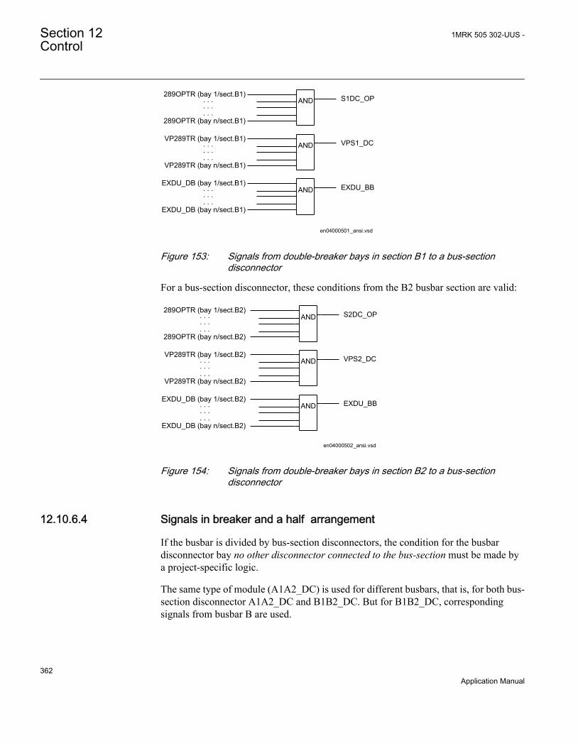
en04000501_ansi.vsd
289OPTR (bay 1/sect.B1) S1DC_OP
VPS1_DC
EXDU_BBAND
289OPTR (bay n/sect.B1)
. . .
. . .
. . .
VP289TR (bay 1/sect.B1)
VP289TR (bay n/sect.B1)
EXDU_DB (bay 1/sect.B1)
EXDU_DB (bay n/sect.B1)
. . .
. . .
. . .
. . .
. . .
. . .
AND
AND
ANSI04000501 V1 EN
Figure 153: Signals from double-breaker bays in section B1 to a bus-sectiondisconnector
For a bus-section disconnector, these conditions from the B2 busbar section are valid:
en04000502_ansi.vsd
289OPTR (bay 1/sect.B2) S2DC_OP
VPS2_DC
EXDU_BB
AND
289OPTR (bay n/sect.B2)
. . .
. . .
. . .
VP289TR (bay 1/sect.B2)
VP289TR (bay n/sect.B2)
EXDU_DB (bay 1/sect.B2)
EXDU_DB (bay n/sect.B2)
. . .
. . .
. . .
. . .
. . .
. . .AND
AND
ANSI04000502 V1 EN
Figure 154: Signals from double-breaker bays in section B2 to a bus-sectiondisconnector
12.10.6.4 Signals in breaker and a half arrangement
If the busbar is divided by bus-section disconnectors, the condition for the busbardisconnector bay no other disconnector connected to the bus-section must be made bya project-specific logic.
The same type of module (A1A2_DC) is used for different busbars, that is, for both bus-section disconnector A1A2_DC and B1B2_DC. But for B1B2_DC, correspondingsignals from busbar B are used.
Section 12 1MRK 505 302-UUS -Control
362Application Manual

en04000503_ansi.vsd
Section 1 Section 2
A1A2_DC(BS)B1B2_DC(BS)
BH_LINE
(WA1)A1(WA2)B1 B2
A2
BH_LINE BH_LINE BH_LINE
ANSI04000503 V1 EN
Figure 155: Busbars divided by bus-section disconnectors (circuit breakers)
The project-specific logic is the same as for the logic for the double-breaker configuration.
Signal S1DC_OP All disconnectors on bus-section 1 are open.
S2DC_OP All disconnectors on bus-section 2 are open.
VPS1_DC The switch status of disconnectors on bus-section 1 is valid.
VPS2_DC The switch status of disconnectors on bus-section 2 is valid.
EXDU_BB No transmission error from breaker and a half (BH) that contains the aboveinformation.
12.10.7 Interlocking for busbar grounding switch BB_ES (3)
12.10.7.1 Application
The interlocking for busbar grounding switch (BB_ES, 3) function is used for onebusbar grounding switch on any busbar parts according to figure 156.
89G
en04000504.vsdANSI04000504 V1 EN
Figure 156: Switchyard layout BB_ES (3)
The signals from other bays connected to the module BB_ES are described below.
1MRK 505 302-UUS - Section 12Control
363Application Manual
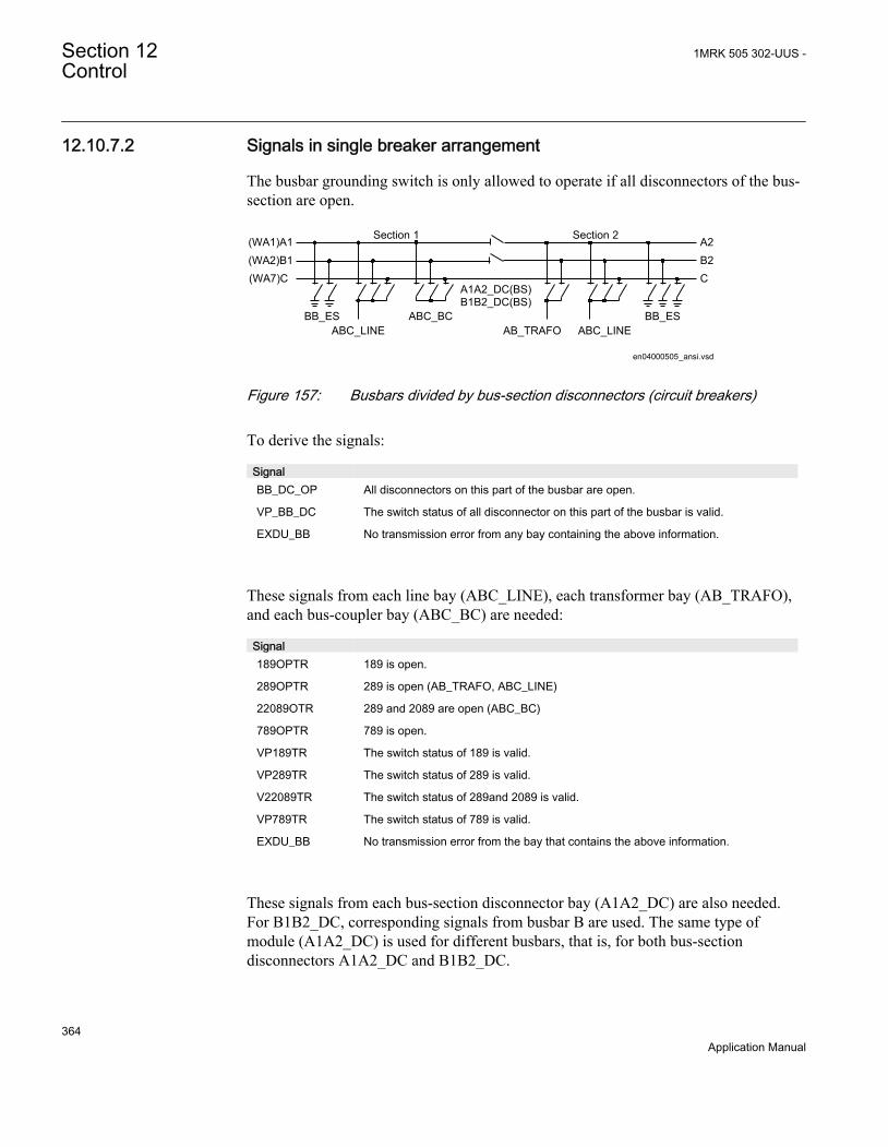
12.10.7.2 Signals in single breaker arrangement
The busbar grounding switch is only allowed to operate if all disconnectors of the bus-section are open.
en04000505_ansi.vsd
Section 1 Section 2
A1A2_DC(BS)B1B2_DC(BS)
AB_TRAFO ABC_LINEBB_ES
ABC_LINE
(WA1)A1(WA2)B1(WA7)C C
B2A2
BB_ESABC_BC
ANSI04000505 V1 EN
Figure 157: Busbars divided by bus-section disconnectors (circuit breakers)
To derive the signals:
Signal BB_DC_OP All disconnectors on this part of the busbar are open.
VP_BB_DC The switch status of all disconnector on this part of the busbar is valid.
EXDU_BB No transmission error from any bay containing the above information.
These signals from each line bay (ABC_LINE), each transformer bay (AB_TRAFO),and each bus-coupler bay (ABC_BC) are needed:
Signal 189OPTR 189 is open.
289OPTR 289 is open (AB_TRAFO, ABC_LINE)
22089OTR 289 and 2089 are open (ABC_BC)
789OPTR 789 is open.
VP189TR The switch status of 189 is valid.
VP289TR The switch status of 289 is valid.
V22089TR The switch status of 289and 2089 is valid.
VP789TR The switch status of 789 is valid.
EXDU_BB No transmission error from the bay that contains the above information.
These signals from each bus-section disconnector bay (A1A2_DC) are also needed.For B1B2_DC, corresponding signals from busbar B are used. The same type ofmodule (A1A2_DC) is used for different busbars, that is, for both bus-sectiondisconnectors A1A2_DC and B1B2_DC.
Section 12 1MRK 505 302-UUS -Control
364Application Manual

Signal DCOPTR The bus-section disconnector is open.
VPDCTR The switch status of bus-section disconnector DC is valid.
EXDU_DC No transmission error from the bay that contains the above information.
If no bus-section disconnector exists, the signal DCOPTR, VPDCTR and EXDU_DCare set to 1 (TRUE).
If the busbar is divided by bus-section circuit breakers, the signals from the bus-sectioncoupler bay (A1A2_BS) rather than the bus-section disconnector bay (A1A2_DC)must be used. For B1B2_BS, corresponding signals from busbar B are used. The sametype of module (A1A2_BS) is used for different busbars, that is, for both bus-sectioncircuit breakers A1A2_BS and B1B2_BS.
Signal 189OPTR 189 is open.
289OPTR 289 is open.
VP189TR The switch status of 189 is valid.
VP289TR The switch status of 289 is valid.
EXDU_BS No transmission error from the bay BS (bus-section coupler bay) that contains theabove information.
For a busbar grounding switch, these conditions from the A1 busbar section are valid:
en04000506_ansi.vsd
189OPTR (bay 1/sect.A1) BB_DC_OP
VP_BB_DC
EXDU_BB
189OPTR (bay n/sect.A1)
. . .
. . .
. . .
VP189TR (bay 1/sect.A1)
VP189TR (bay n/sect.A1)VPDCTR (A1/A2)
EXDU_BB (bay n/sect.A1)
. . .
. . .
. . .
. . .
. . .
. . .AND
DCOPTR (A1/A2)
EXDU_BB (bay 1/sect.A1)
EXDU_DC (A1/A2)
AND
AND
ANSI04000506 V1 EN
Figure 158: Signals from any bays in section A1 to a busbar grounding switch inthe same section
For a busbar grounding switch, these conditions from the A2 busbar section are valid:
1MRK 505 302-UUS - Section 12Control
365Application Manual

189OPTR (bay 1/sect.A2)BB_DC_OP
VP_BB_DC
EXDU_BB
en04000507_ansi.vsd
189OPTR (bay n/sect.A2)
. . .
. . .
. . .
VP189TR (bay 1/sect.A2)
VP189TR (bay n/sect.A2)VPDCTR (A1/A2)
EXDU_BB (bay n/sect.A2)
. . .
. . .
. . .
. . .
. . .
. . .
AND
DCOPTR (A1/A2)
EXDU_BB (bay 1/sect.A2)
EXDU_DC (A1/A2)
AND
AND
ANSI04000507 V1 EN
Figure 159: Signals from any bays in section A2 to a busbar grounding switch inthe same section
For a busbar grounding switch, these conditions from the B1 busbar section are valid:
Section 12 1MRK 505 302-UUS -Control
366Application Manual

289OPTR(22089OTR)(bay 1/sect.B1)BB_DC_OP
VP_BB_DC
EXDU_BB
en04000508_ansi.vsd
289PTR (22089OTR)(bay n/sect.B1)
. . .
. . .
. . .
VP289TR(V22089TR) (bay 1/sect.B1)
VP289TR(V22089TR) (bay n/sect.B1)VPDCTR (B1/B2)
EXDU_BB (bay n/sect.B1)
. . .
. . .
. . .
. . .
. . .
. . .
AND
AND
AND
DCOPTR (B1/B2)
EXDU_BB (bay 1/sect.B1)
EXDU_DC (B1/B2)
ANSI04000508 V1 EN
Figure 160: Signals from any bays in section B1 to a busbar grounding switch inthe same section
For a busbar grounding switch, these conditions from the B2 busbar section are valid:
1MRK 505 302-UUS - Section 12Control
367Application Manual

289OPTR(22089OTR) (bay 1/sect.B2)BB_DC_OP
VP_BB_DC
EXDU_BB
en04000509_ansi.vsd
289OPTR(22089OTR) (bay n/sect.B2)
. . .
. . .
. . .
VP289TR(V22089TR) (bay 1/sect.B2)
VP289TR(V22089TR) (bay n/sect.B2)VPDCTR (B1/B2)
EXDU_BB (bay n/sect.B2)
. . .
. . .
. . .
. . .
. . .
. . .
AND
DCOPTR (B1/B2)
EXDU_BB (bay 1/sect.B2)
EXDU_DC (B1/B2)
AND
AND
ANSI04000509 V1 EN
Figure 161: Signals from any bays in section B2 to a busbar grounding switch inthe same section
For a busbar grounding switch on bypass busbar C, these conditions are valid:
789OPTR (bay 1)BB_DC_OP
VP_BB_DC
EXDU_BB
en04000510_ansi.vsd
AND
AND
AND
789OPTR (bay n)
. . .
. . .
. . .
VP789TR (bay 1)
VP789TR (bay n)
EXDU_BB (bay 1)
EXDU_BB (bay n)
. . .
. . .
. . .
. . .
. . .
. . .
ANSI04000510 V1 EN
Figure 162: Signals from bypass busbar to busbar grounding switch
Section 12 1MRK 505 302-UUS -Control
368Application Manual

12.10.7.3 Signals in double-breaker arrangement
The busbar grounding switch is only allowed to operate if all disconnectors of the bussection are open.
en04000511_ansi.vsd
Section 1 Section 2
A1A2_DC(BS)B1B2_DC(BS) BB_ESBB_ES
DB_BUS
(WA1)A1(WA2)B1 B2
A2
DB_BUS
ANSI04000511 V1 EN
Figure 163: Busbars divided by bus-section disconnectors (circuit breakers)
To derive the signals:
Signal BB_DC_OP All disconnectors of this part of the busbar are open.
VP_BB_DC The switch status of all disconnectors on this part of the busbar are valid.
EXDU_BB No transmission error from any bay that contains the above information.
These signals from each double-breaker bay (DB_BUS) are needed:
Signal 189OPTR 189 is open.
289OPTR 289 is open.
VP189TR The switch status of 189 is valid.
VP289TR The switch status of 289 is valid.
EXDU_DB No transmission error from the bay that contains the above information.
These signals from each bus-section disconnector bay (A1A2_DC) are also needed.For B1B2_DC, corresponding signals from busbar B are used. The same type ofmodule (A1A2_DC) is used for different busbars, that is, for both bus-sectiondisconnectors A1A2_DC and B1B2_DC.
Signal DCOPTR The bus-section disconnector is open.
VPDCTR The switch status of bus-section disconnector DC is valid.
EXDU_DC No transmission error from the bay that contains the above information.
1MRK 505 302-UUS - Section 12Control
369Application Manual

The logic is identical to the double busbar configuration described in section “Signalsin single breaker arrangement”.
12.10.7.4 Signals in breaker and a half arrangement
The busbar grounding switch is only allowed to operate if all disconnectors of the bus-section are open.
en04000512_ansi.vsd
Section 1 Section 2
A1A2_DC(BS)B1B2_DC(BS) BB_ESBB_ES
BH_LINE
(WA1)A1(WA2)B1 B2
A2
BH_LINE
ANSI04000512 V1 EN
Figure 164: Busbars divided by bus-section disconnectors (circuit breakers)
The project-specific logic are the same as for the logic for the double busbarconfiguration described in section “Signals in single breaker arrangement”.
Signal BB_DC_OP All disconnectors on this part of the busbar are open.
VP_BB_DC The switch status of all disconnectors on this part of the busbar is valid.
EXDU_BB No transmission error from any bay that contains the above information.
12.10.8 Interlocking for double CB bay DB (3)
12.10.8.1 Application
The interlocking for a double busbar double circuit breaker bay including DB_BUS_A(3), DB_BUS_B (3) and DB_LINE (3) functions are used for a line connected to adouble busbar arrangement according to figure 165.
Section 12 1MRK 505 302-UUS -Control
370Application Manual

WA1 (A)
WA2 (B)
189189G
289G
989G
6189
989
289489G
589G
389G
6289
DB_BUS_B
DB_LINE
DB_BUS_A
en04000518_ansi.vsd
252152
ANSI04000518 V1 EN
Figure 165: Switchyard layout double circuit breaker
Three types of interlocking modules per double circuit breaker bay are defined.DB_BUS_A (3) handles the circuit breaker QA1 that is connected to busbar WA1 andthe disconnectors and earthing switches of this section. DB_BUS_B (3) handles thecircuit breaker QA2 that is connected to busbar WA2 and the disconnectors andearthing switches of this section.
For a double circuit-breaker bay, the modules DB_BUS_A, DB_LINE andDB_BUS_B must be used.
12.10.8.2 Configuration setting
For application without 989 and 989G, just set the appropriate inputs to open state anddisregard the outputs. In the functional block diagram, 0 and 1 are designated0=FALSE and 1=TRUE:
• 989_OP = 1• 989_CL = 0
• 989G_OP = 1• 989G_CL = 0
1MRK 505 302-UUS - Section 12Control
371Application Manual
If, in this case, line voltage supervision is added, then rather than setting 989 to openstate, specify the state of the voltage supervision:
• 989_OP = VOLT_OFF• 989_CL = VOLT_ON
If there is no voltage supervision, then set the corresponding inputs as follows:
• VOLT_OFF = 1• VOLT_ON = 0
12.10.9 Interlocking for breaker-and-a-half diameter BH (3)
12.10.9.1 Application
The interlocking for breaker-and-a-half diameter (BH_CONN(3), BH_LINE_A(3),BH_LINE_B(3)) functions are used for lines connected to a breaker-and-a-halfdiameter according to figure 166.
Section 12 1MRK 505 302-UUS -Control
372Application Manual
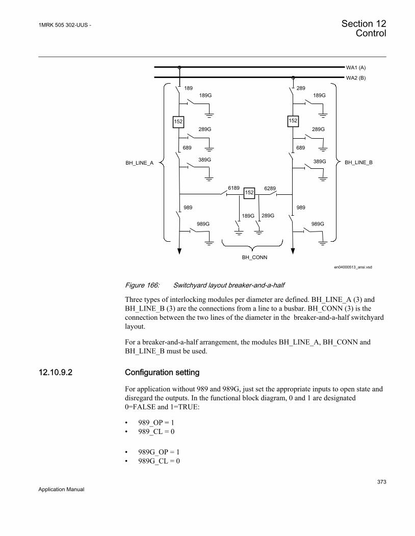
WA1 (A)
WA2 (B)
189189G
289G
989G
689
989
289189G
289G
389G
689
389G
62896189
189G 289G989G
989
BH_LINE_A BH_LINE_B
BH_CONN
en04000513_ansi.vsd
152152
152
ANSI04000513 V1 EN
Figure 166: Switchyard layout breaker-and-a-half
Three types of interlocking modules per diameter are defined. BH_LINE_A (3) andBH_LINE_B (3) are the connections from a line to a busbar. BH_CONN (3) is theconnection between the two lines of the diameter in the breaker-and-a-half switchyardlayout.
For a breaker-and-a-half arrangement, the modules BH_LINE_A, BH_CONN andBH_LINE_B must be used.
12.10.9.2 Configuration setting
For application without 989 and 989G, just set the appropriate inputs to open state anddisregard the outputs. In the functional block diagram, 0 and 1 are designated0=FALSE and 1=TRUE:
• 989_OP = 1• 989_CL = 0
• 989G_OP = 1• 989G_CL = 0
1MRK 505 302-UUS - Section 12Control
373Application Manual
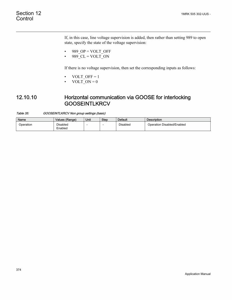
If, in this case, line voltage supervision is added, then rather than setting 989 to openstate, specify the state of the voltage supervision:
• 989_OP = VOLT_OFF• 989_CL = VOLT_ON
If there is no voltage supervision, then set the corresponding inputs as follows:
• VOLT_OFF = 1• VOLT_ON = 0
12.10.10 Horizontal communication via GOOSE for interlockingGOOSEINTLKRCV
Table 35: GOOSEINTLKRCV Non group settings (basic)
Name Values (Range) Unit Step Default DescriptionOperation Disabled
Enabled- - Disabled Operation Disabled/Enabled
Section 12 1MRK 505 302-UUS -Control
374Application Manual

Section 13 Logic
13.1 Trip matrix logic TMAGAPC
13.1.1 IdentificationFunction description IEC 61850
identificationIEC 60617identification
ANSI/IEEE C37.2device number
Trip matrix logic TMAGAPC - -
13.1.2 ApplicationTrip matrix logic TMAGAPC function is used to route trip signals and other logicaloutput signals to different output contacts on the IED.
The trip matrix logic function has 3 output signals and these outputs can be connectedto physical tripping outputs according to the specific application needs for settablepulse or steady output.
13.1.3 Setting guidelinesOperation: Operation of function Enabled/Disabled.
PulseTime: Defines the pulse time when in Pulsed mode. When used for direct trippingof circuit breaker(s) the pulse time delay shall be set to approximately 0.150 seconds inorder to obtain satisfactory minimum duration of the trip pulse to the circuit breakertrip coils.
OnDelay: Used to prevent output signals to be given for spurious inputs. Normally setto 0 or a low value.
OffDelay: Defines a delay of the reset of the outputs after the activation conditions nolonger are fulfilled. It is only used in Steady mode. When used for direct tripping ofcircuit breaker(s) the off delay time shall be set to at least 0.150 seconds in order toobtain a satisfactory minimum duration of the trip pulse to the circuit breaker trip coils.
ModeOutputx: Defines if output signal OUTPUTx (where x=1-3) is Steady or Pulsed.
1MRK 505 302-UUS - Section 13Logic
375Application Manual
13.2 Logic for group alarm ALMCALH
13.2.1 IdentificationFunction description IEC 61850
identificationIEC 60617identification
ANSI/IEEE C37.2device number
Logic for group alarm ALMCALH - -
13.2.2 ApplicationGroup alarm logic function ALMCALH is used to route alarm signals to differentLEDs and/or output contacts on the IED.
ALMCALH output signal and the physical outputs allows the user to adapt the alarmsignal to physical tripping outputs according to the specific application needs.
13.2.3 Setting guidelinesOperation: Enabled or Disabled
13.3 Logic for group alarm WRNCALH
13.3.1 IdentificationFunction description IEC 61850
identificationIEC 60617identification
ANSI/IEEE C37.2device number
Logic for group warning WRNCALH - -
13.3.1.1 Application
Group warning logic function WRNCALH is used to route warning signals to LEDs and/or output contacts on the IED.
WRNCALH output signal WARNING and the physical outputs allows the user toadapt the warning signal to physical tripping outputs according to the specificapplication needs.
Section 13 1MRK 505 302-UUS -Logic
376Application Manual
13.3.1.2 Setting guidelines
OperationEnabled or Disabled
13.4 Logic for group indication INDCALH
13.4.1 IdentificationFunction description IEC 61850
identificationIEC 60617identification
ANSI/IEEE C37.2device number
Logic for group indication INDCALH - -
13.4.1.1 Application
Group indication logic function INDCALH is used to route indication signals todifferent LEDs and/or output contacts on the IED.
INDCALH output signal IND and the physical outputs allows the user to adapt theindication signal to physical outputs according to the specific application needs.
13.4.1.2 Setting guidelines
Operation: Enabled or Disabled
13.5 Configurable logic blocks
13.5.1 ApplicationA set of standard logic blocks, like AND, OR etc, and timers are available for adaptingthe IED configuration to the specific application needs. Additional logic blocks that,beside the normal logical function, have the capability to propagate timestamp andquality are also available. Those blocks have a designation including the letters QT,like ANDQT, ORQT etc.
There are no settings for AND gates, OR gates, inverters or XOR gates as well as, forANDQT gates, ORQT gates or XORQT gates.
For normal On/Off delay and pulse timers the time delays and pulse lengths are setfrom the local HMI or via the PST tool.
1MRK 505 302-UUS - Section 13Logic
377Application Manual
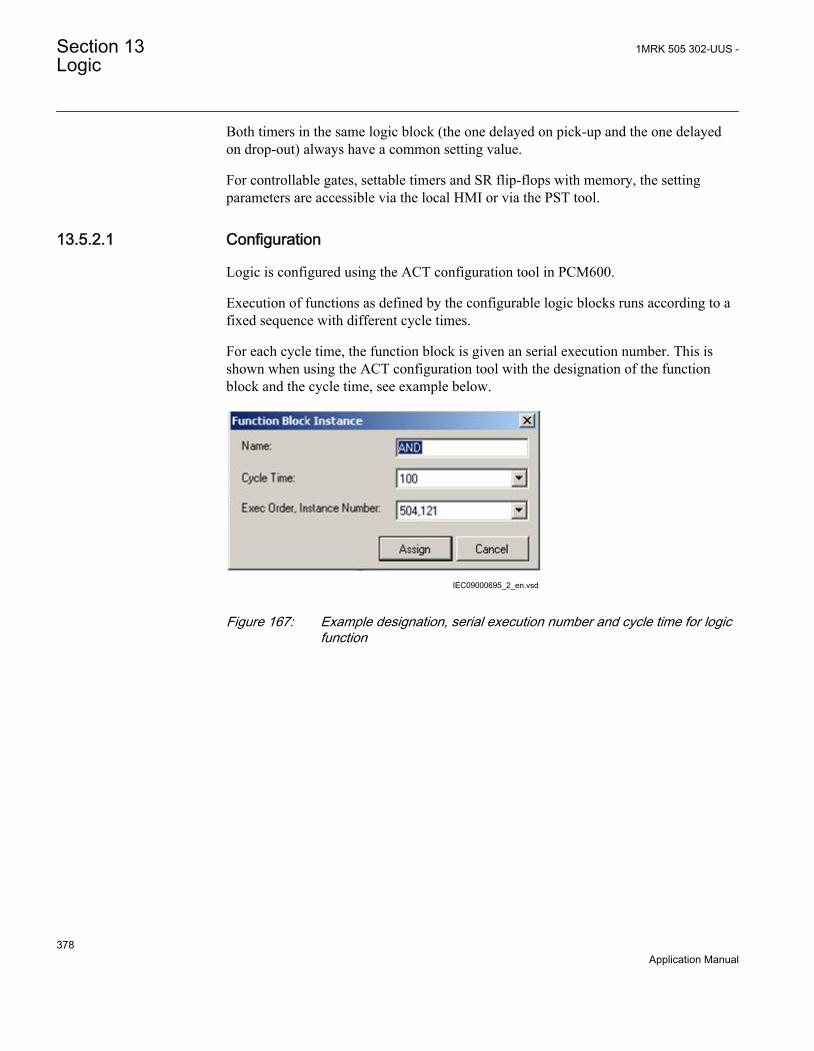
Both timers in the same logic block (the one delayed on pick-up and the one delayedon drop-out) always have a common setting value.
For controllable gates, settable timers and SR flip-flops with memory, the settingparameters are accessible via the local HMI or via the PST tool.
13.5.2.1 Configuration
Logic is configured using the ACT configuration tool in PCM600.
Execution of functions as defined by the configurable logic blocks runs according to afixed sequence with different cycle times.
For each cycle time, the function block is given an serial execution number. This isshown when using the ACT configuration tool with the designation of the functionblock and the cycle time, see example below.
IEC09000695_2_en.vsdIEC09000695 V2 EN
Figure 167: Example designation, serial execution number and cycle time for logicfunction
Section 13 1MRK 505 302-UUS -Logic
378Application Manual

IEC09000310-1-en.vsdIEC09000310 V1 EN
Figure 168: Example designation, serial execution number and cycle time for logicfunction that also propagates timestamp and quality of input signals
The execution of different function blocks within the same cycle is determined by theorder of their serial execution numbers. Always remember this when connecting two ormore logical function blocks in series.
Always be careful when connecting function blocks with a fast cycletime to function blocks with a slow cycle time.Remember to design the logic circuits carefully and always check theexecution sequence for different functions. In other cases, additionaltime delays must be introduced into the logic schemes to prevent errors,for example, race between functions.
13.6 Fixed signal function block FXDSIGN
13.6.1 IdentificationFunction description IEC 61850
identificationIEC 60617identification
ANSI/IEEE C37.2device number
Fixed signals FXDSIGN - -
13.6.2 ApplicationThe Fixed signals function FXDSIGN generates nine pre-set (fixed) signals that can beused in the configuration of an IED, either for forcing the unused inputs in other
1MRK 505 302-UUS - Section 13Logic
379Application Manual

function blocks to a certain level/value, or for creating certain logic. Boolean, integer,floating point, string types of signals are available.
Example for use of GRP_OFF signal in FXDSIGNThe Restricted earth fault function REFPDIF (87N) can be used both for auto-transformers and normal transformers.
When used for auto-transformers, information from both windings parts, together withthe neutral point current, needs to be available to the function. This means that threeinputs are needed.
I3PW1CT1I3PW2CT1
I3P
REFPDIF (87N)
ANSI11000083_1_en.vsdANSI11000083 V1 EN
Figure 169: REFPDIF (87N) function inputs for autotransformer application
For normal transformers only one winding and the neutral point is available. Thismeans that only two inputs are used. Since all group connections are mandatory to beconnected, the third input needs to be connected to something, which is the GRP_OFFsignal in FXDSIGN function block.
Section 13 1MRK 505 302-UUS -Logic
380Application Manual

I3PW1CT1I3PW2CT1
I3P
REFPDIF (87N)
ANSI11000084_1_en.vsd
GRP_OFFFXDSIGN
ANSI11000084 V1 EN
Figure 170: REFPDIF (87N) function inputs for normal transformer application
13.7 Boolean 16 to Integer conversion B16I
13.7.1 IdentificationFunction description IEC 61850
identificationIEC 60617identification
ANSI/IEEE C37.2device number
Boolean 16 to integer conversion B16I - -
13.7.2 ApplicationBoolean 16 to integer conversion function B16I is used to transform a set of 16 binary(logical) signals into an integer. It can be used – for example, to connect logical outputsignals from a function (like distance protection) to integer inputs from anotherfunction (like line differential protection). B16I does not have a logical node mapping.
The Boolean 16 to integer conversion function (B16I) will transfer a combination of upto 16 binary inputs INx where 1≤x≤16 to an integer. Each INx represents a valueaccording to the table below from 0 to 32768. This follows the general formula: INx =2x-1 where 1≤x≤16. The sum of all the values on the activated INx will be available onthe output OUT as a sum of the values of all the inputs INx that are activated. OUT isan integer. When all INx where 1≤x≤16 are activated that is = Boolean 1 it correspondsto that integer 65535 is available on the output OUT. B16I function is designed for
1MRK 505 302-UUS - Section 13Logic
381Application Manual

receiving up to 16 booleans input locally. If the BLOCK input is activated, it willfreeze the output at the last value.
Values of each of the different OUTx from function block B16I for 1≤x≤16.
The sum of the value on each INx corresponds to the integer presented on the outputOUT on the function block B16I.
Name of input Type Default Description Value whenactivated
Value whendeactivated
IN1 BOOLEAN 0 Input 1 1 0
IN2 BOOLEAN 0 Input 2 2 0
IN3 BOOLEAN 0 Input 3 4 0
IN4 BOOLEAN 0 Input 4 8 0
IN5 BOOLEAN 0 Input 5 16 0
IN6 BOOLEAN 0 Input 6 32 0
IN7 BOOLEAN 0 Input 7 64 0
IN8 BOOLEAN 0 Input 8 128 0
IN9 BOOLEAN 0 Input 9 256 0
IN10 BOOLEAN 0 Input 10 512 0
IN11 BOOLEAN 0 Input 11 1024 0
IN12 BOOLEAN 0 Input 12 2048 0
IN13 BOOLEAN 0 Input 13 4096 0
IN14 BOOLEAN 0 Input 14 8192 0
IN15 BOOLEAN 0 Input 15 16384 0
IN16 BOOLEAN 0 Input 16 32768 0
The sum of the numbers in column “Value when activated” when all INx (where1≤x≤16) are active that is=1; is 65535. 65535 is the highest boolean value that can beconverted to an integer by the B16I function block.
13.8 Boolean 16 to Integer conversion with logic noderepresentation BTIGAPC
Section 13 1MRK 505 302-UUS -Logic
382Application Manual

13.8.1 IdentificationFunction description IEC 61850
identificationIEC 60617identification
ANSI/IEEE C37.2device number
Boolean 16 to integer conversion withlogic node representation
BTIGAPC - -
13.8.2 ApplicationBoolean 16 to integer conversion with logic node representation function BTIGAPC isused to transform a set of 16 binary (logical) signals into an integer. BTIGAPC canreceive an integer from a station computer – for example, over IEC 61850–8–1. Thesefunctions are very useful when you want to generate logical commands (for selectorswitches or voltage controllers) by inputting an integer number. BTIGAPC has alogical node mapping in IEC 61850.
The Boolean 16 to integer conversion function (BTIGAPC) will transfer a combinationof up to 16 binary inputs INx where 1≤x≤16 to an integer. Each INx represents a valueaccording to the table below from 0 to 32768. This follows the general formula: INx =2x-1 where 1≤x≤16. The sum of all the values on the activated INx will be available onthe output OUT as a sum of the values of all the inputs INx that are activated. OUT isan integer. When all INx where 1≤x≤16 are activated that is = Boolean 1 it correspondsto that integer 65535 is available on the output OUT. BTIGAPC function is designedfor receiving up to 16 booleans input locally. If the BLOCK input is activated, it willfreeze the output at the last value.
Values of each of the different OUTx from function block BTIGAPC for 1≤x≤16.
The sum of the value on each INx corresponds to the integer presented on the outputOUT on the function block BTIGAPC.
Name of input Type Default Description Value whenactivated
Value whendeactivated
IN1 BOOLEAN 0 Input 1 1 0
IN2 BOOLEAN 0 Input 2 2 0
IN3 BOOLEAN 0 Input 3 4 0
IN4 BOOLEAN 0 Input 4 8 0
IN5 BOOLEAN 0 Input 5 16 0
IN6 BOOLEAN 0 Input 6 32 0
IN7 BOOLEAN 0 Input 7 64 0
IN8 BOOLEAN 0 Input 8 128 0
IN9 BOOLEAN 0 Input 9 256 0
IN10 BOOLEAN 0 Input 10 512 0
Table continues on next page
1MRK 505 302-UUS - Section 13Logic
383Application Manual

Name of input Type Default Description Value whenactivated
Value whendeactivated
IN11 BOOLEAN 0 Input 11 1024 0
IN12 BOOLEAN 0 Input 12 2048 0
IN13 BOOLEAN 0 Input 13 4096 0
IN14 BOOLEAN 0 Input 14 8192 0
IN15 BOOLEAN 0 Input 15 16384 0
IN16 BOOLEAN 0 Input 16 32768 0
The sum of the numbers in column “Value when activated” when all INx (where1≤x≤16) are active that is=1; is 65535. 65535 is the highest boolean value that can beconverted to an integer by the BTIGAPC function block.
13.9 Integer to Boolean 16 conversion IB16
13.9.1 IdentificationFunction description IEC 61850
identificationIEC 60617identification
ANSI/IEEE C37.2device number
Integer to boolean 16 conversion IB16 - -
13.9.2 ApplicationInteger to boolean 16 conversion function (IB16) is used to transform an integer into aset of 16 binary (logical) signals. It can be used – for example, to connect integeroutput signals from one function to binary (logical) inputs to another function. IB16function does not have a logical node mapping.
The Boolean 16 to integer conversion function (IB16) will transfer a combination of upto 16 binary inputs INx where 1≤x≤16 to an integer. Each INx represents a valueaccording to the table below from 0 to 32768. This follows the general formula: INx =2x-1 where 1≤x≤16. The sum of all the values on the activated INx will be available onthe output OUT as a sum of the values of all the inputs INx that are activated. OUT isan integer. When all INx where 1≤x≤16 are activated that is = Boolean 1 it correspondsto that integer 65535 is available on the output OUT. IB16 function is designed forreceiving up to 16 booleans input locally. If the BLOCK input is activated, it willfreeze the output at the last value.
Values of each of the different OUTx from function block IB16 for 1≤x≤16.
Section 13 1MRK 505 302-UUS -Logic
384Application Manual

The sum of the value on each INx corresponds to the integer presented on the outputOUT on the function block IB16.
Name of input Type Default Description Value whenactivated
Value whendeactivated
IN1 BOOLEAN 0 Input 1 1 0
IN2 BOOLEAN 0 Input 2 2 0
IN3 BOOLEAN 0 Input 3 4 0
IN4 BOOLEAN 0 Input 4 8 0
IN5 BOOLEAN 0 Input 5 16 0
IN6 BOOLEAN 0 Input 6 32 0
IN7 BOOLEAN 0 Input 7 64 0
IN8 BOOLEAN 0 Input 8 128 0
IN9 BOOLEAN 0 Input 9 256 0
IN10 BOOLEAN 0 Input 10 512 0
IN11 BOOLEAN 0 Input 11 1024 0
IN12 BOOLEAN 0 Input 12 2048 0
IN13 BOOLEAN 0 Input 13 4096 0
IN14 BOOLEAN 0 Input 14 8192 0
IN15 BOOLEAN 0 Input 15 16384 0
IN16 BOOLEAN 0 Input 16 32768 0
The sum of the numbers in column “Value when activated” when all INx (where1≤x≤16) are active that is=1; is 65535. 65535 is the highest boolean value that can beconverted to an integer by the IB16 function block.
13.10 Integer to Boolean 16 conversion with logic noderepresentation ITBGAPC
13.10.1 IdentificationFunction description IEC 61850
identificationIEC 60617identification
ANSI/IEEE C37.2device number
Integer to boolean 16 conversion withlogic node representation
ITBGAPC - -
1MRK 505 302-UUS - Section 13Logic
385Application Manual

13.10.2 ApplicationInteger to boolean 16 conversion with logic node representation function (ITBGAPC)is used to transform an integer into a set of 16 boolean signals. ITBGAPC function canreceive an integer from a station computer – for example, over IEC 61850–8–1. Thisfunction is very useful when the user wants to generate logical commands (for selectorswitches or voltage controllers) by inputting an integer number. ITBGAPC functionhas a logical node mapping in IEC 61850.
The Integer to Boolean 16 conversion with logic node representation function(ITBGAPC) will transfer an integer with a value between 0 to 65535 communicatedvia IEC61850 and connected to the ITBGAPC function block to a combination ofactivated outputs OUTx where 1≤x≤16.
The values of the different OUTx are according to the Table 36.
If the BLOCK input is activated, it freezes the logical outputs at the last value.
Table 36: Output signals
Name of OUTx Type Description Value whenactivated
Value whendeactivated
OUT1 BOOLEAN Output 1 1 0
OUT2 BOOLEAN Output 2 2 0
OUT3 BOOLEAN Output 3 4 0
OUT4 BOOLEAN Output 4 8 0
OUT5 BOOLEAN Output 5 16 0
OUT6 BOOLEAN Output 6 32 0
OUT7 BOOLEAN Output 7 64 0
OUT8 BOOLEAN Output 8 128 0
OUT9 BOOLEAN Output 9 256 0
OUT10 BOOLEAN Output 10 512 0
OUT11 BOOLEAN Output 11 1024 0
OUT12 BOOLEAN Output 12 2048 0
OUT13 BOOLEAN Output 13 4096 0
OUT14 BOOLEAN Output 14 8192 0
OUT15 BOOLEAN Output 15 16384 0
OUT16 BOOLEAN Output 16 32768 0
The sum of the numbers in column “Value when activated” when all OUTx (1≤x≤16)are active equals 65535. This is the highest integer that can be converted by theITBGAPC function block.
Section 13 1MRK 505 302-UUS -Logic
386Application Manual

13.11 Elapsed time integrator with limit transgression andoverflow supervision TEIGAPC
13.11.1 IdentificationFunction Description IEC 61850
identificationIEC 60617identification
ANSI/IEEE C37.2 devicenumber
Elapsed time integrator TEIGAPC - -
13.11.2 ApplicationThe function TEIGAPC is used for user-defined logics and it can also be used fordifferent purposes internally in the IED. An application example is the integration ofelapsed time during the measurement of neutral point voltage or neutral current at earth-fault conditions.
Settable time limits for warning and alarm are provided. The time limit for overflowindication is fixed to 999999.9 seconds.
13.11.3 Setting guidelinesThe settings tAlarm and tWarning are user settable limits defined in seconds. Theachievable resolution of the settings depends on the level of the values defined.
A resolution of 10 ms can be achieved when the settings are defined within the range
1.00 second ≤ tAlarm ≤ 99 999.99 seconds
1.00 second ≤ tWarning ≤ 99 999.99 seconds.
If the values are above this range the resolution becomes lower
99 999.99 seconds ≤ tAlarm ≤ 999 999.9 seconds
99 999.99 seconds≤ tWarning ≤ 999 999.9 seconds
Note that tAlarm and tWarning are independent settings, that is, there isno check if tAlarm > tWarning.
The limit for the overflow supervision is fixed at 999999.9 seconds.
1MRK 505 302-UUS - Section 13Logic
387Application Manual

388
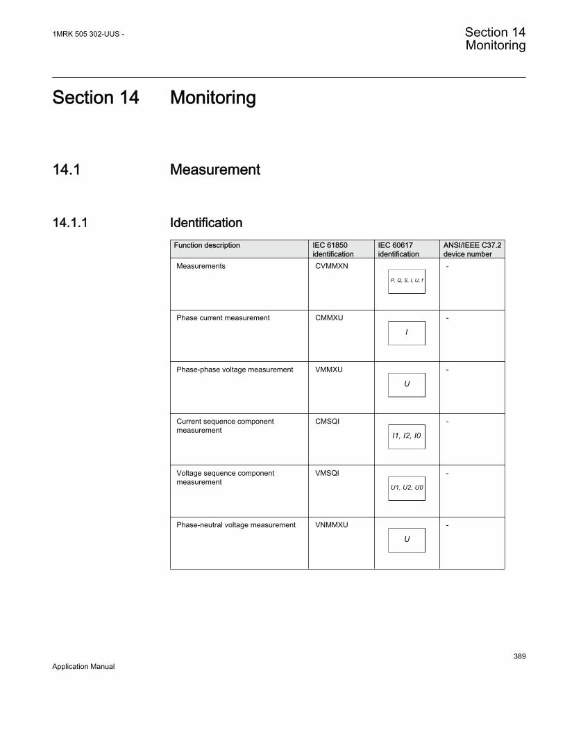
Section 14 Monitoring
14.1 Measurement
14.1.1 IdentificationFunction description IEC 61850
identificationIEC 60617identification
ANSI/IEEE C37.2device number
Measurements CVMMXN
P, Q, S, I, U, f
SYMBOL-RR V1 EN
-
Phase current measurement CMMXU
I
SYMBOL-SS V1 EN
-
Phase-phase voltage measurement VMMXU
U
SYMBOL-UU V1 EN
-
Current sequence componentmeasurement
CMSQI
I1, I2, I0
SYMBOL-VV V1 EN
-
Voltage sequence componentmeasurement
VMSQI
U1, U2, U0
SYMBOL-TT V1 EN
-
Phase-neutral voltage measurement VNMMXU
U
SYMBOL-UU V1 EN
-
1MRK 505 302-UUS - Section 14Monitoring
389Application Manual

14.1.2 ApplicationMeasurement functions is used for power system measurement, supervision andreporting to the local HMI, monitoring tool within PCM600 or to station level forexample, via IEC 61850. The possibility to continuously monitor measured values ofactive power, reactive power, currents, voltages, frequency, power factor etc. is vitalfor efficient production, transmission and distribution of electrical energy. It providesto the system operator fast and easy overview of the present status of the power system.Additionally, it can be used during testing and commissioning of protection and controlIEDs in order to verify proper operation and connection of instrument transformers(CTs and VTs). During normal service by periodic comparison of the measured valuefrom the IED with other independent meters the proper operation of the IED analogmeasurement chain can be verified. Finally, it can be used to verify proper directionorientation for distance or directional overcurrent protection function.
The available measured values of an IED are depending on the actualhardware (TRM) and the logic configuration made in PCM600.
All measured values can be supervised with four settable limits that is, low-low limit,low limit, high limit and high-high limit. A zero clamping reduction is also supported,that is, the measured value below a settable limit is forced to zero which reduces theimpact of noise in the inputs.
Dead-band supervision can be used to report measured signal value to station levelwhen change in measured value is above set threshold limit or time integral of allchanges since the last time value updating exceeds the threshold limit. Measure valuecan also be based on periodic reporting.
Main menu/Measurement/Monitoring/Service values/CVMMXN
The measurement function, CVMMXN, provides the following power system quantities:
• P, Q and S: three phase active, reactive and apparent power• PF: power factor• V: phase-to-phase voltage magnitude• I: phase current magnitude• F: power system frequency
,The measuring functions CMMXU, VMMXU and VNMMXU provide physicalquantities:
• I: phase currents (magnitude and angle) (CMMXU)• V: voltages (phase-to-ground and phase-to-phase voltage, magnitude and angle)
(VMMXU, VNMMXU)
Section 14 1MRK 505 302-UUS -Monitoring
390Application Manual

The CVMMXN function calculates three-phase power quantities by using fundamentalfrequency phasors (DFT values) of the measured current respectively voltage signals.The measured power quantities are available either, as instantaneously calculatedquantities or, averaged values over a period of time (low pass filtered) depending onthe selected settings.
It is possible to calibrate the measuring function above to get better then class 0.5presentation. This is accomplished by angle and magnitude compensation at 5, 30 and100% of rated current and at 100% of rated voltage.
The power system quantities provided, depends on the actual hardware,(TRM) and the logic configuration made in PCM600.
The measuring functions CMSQI and VMSQI provide sequence component quantities:
• I: sequence currents (positive, zero, negative sequence, magnitude and angle)• V: sequence voltages (positive, zero and negative sequence, magnitude and angle).
14.1.3 Zero clampingThe measuring functions, CVMMXN, CMMXU, VMMXU and VNMMXU have nointerconnections regarding any setting or parameter.
Zero clampings are also entirely handled by the ZeroDb for each and every signalseparately for each of the functions. For example, the zero clamping of U12 is handledby UL12ZeroDb in VMMXU, zero clamping of I1 is handled by IL1ZeroDb inCMMXU ETC.
Example how CVMMXN is operating:
The following outputs can be observed on the local HMI under Monitoring/Servicevalues/SRV1
S Apparent three-phase power
P Active three-phase power
Q Reactive three-phase power
PF Power factor
ILAG I lagging U
ILEAD I leading U
U System mean voltage, calculated according to selected mode
I System mean current, calculated according to selected mode
F Frequency
1MRK 505 302-UUS - Section 14Monitoring
391Application Manual

The settings for this function is found under Setting/General setting/Monitoring/Service values/SRV1
It can be seen that:
• When system voltage falls below UGenZeroDB, the shown value for S, P, Q, PF,ILAG, ILEAD, U and F on the local HMI is forced to zero
• When system current falls below IGenZeroDB, the shown value for S, P, Q, PF,ILAG, ILEAD, U and F on the local HMI is forced to zero
• When the value of a single signal falls below the set dead band for that specificsignal, the value shown on the local HMI is forced to zero. For example, ifapparent three-phase power falls below SZeroDb the value for S on the local HMIis forced to zero.
14.1.4 Setting guidelinesThe available setting parameters of the measurement function CVMMXN, CMMXU,VMMXU, CMSQI, VMSQI, VNMMXU are depending on the actual hardware (TRM)and the logic configuration made in PCM600.
The parameters for the Measurement functions CVMMXN, CMMXU, VMMXU,CMSQI, VMSQI, VNMMXU are set via the local HMI or PCM600.
GlobalBaseSel: Selects the global base value group used by the function to define(IBase), (VBase) and (SBase).
Operation: Disabled/Enabled. Every function instance (CVMMXN, CMMXU,VMMXU, CMSQI, VMSQI, VNMMXU) can be taken in operation (Enabled) or outof operation (Disabled).
The following general settings can be set for the Measurement function (CVMMXN).
PowMagFact: Magnitude factor to scale power calculations.
PowAngComp: Angle compensation for phase shift between measured I & V.
Mode: Selection of measured current and voltage. There are 9 different ways ofcalculating monitored three-phase values depending on the available VT inputsconnected to the IED. See parameter group setting table.
k: Low pass filter coefficient for power measurement, V and I.
VGenZeroDb: Minimum level of voltage in % of VBase used as indication of zerovoltage (zero point clamping). If measured value is below VGenZeroDb calculated S,P, Q and PF will be zero.
Section 14 1MRK 505 302-UUS -Monitoring
392Application Manual

IGenZeroDb: Minimum level of current in % of IBase used as indication of zerocurrent (zero point clamping). If measured value is below IGenZeroDb calculated S, P,Q and PF will be zero.
VMagCompY: Magnitude compensation to calibrate voltage measurements at Y% ofVn, where Y is equal to 5, 30 or 100.
IMagCompY: Magnitude compensation to calibrate current measurements at Y% of In,where Y is equal to 5, 30 or 100.
IAngCompY: Angle compensation to calibrate angle measurements at Y% of In, whereY is equal to 5, 30 or 100.
Parameters IBase, Ubase and SBase have been implemented as asettings instead of a parameters, which means that if the values of theparameters are changed there will be no restart of the application. Asrestart is required to activate new parameters values, the IED must berestarted in some way. Either manually or by changing some otherparameter at the same time.
The following general settings can be set for the Phase-phase current measurement(CMMXU).
IMagCompY: Magnitude compensation to calibrate current measurements at Y% of In,where Y is equal to 5, 30 or 100.
IAngCompY: Angle compensation to calibrate angle measurements at Y% of In, whereY is equal to 5, 30 or 100.
The following general settings can be set for the Phase-phase voltage measurement(VMMXU).
VMagCompY: Amplitude compensation to calibrate voltage measurements at Y% ofVn, where Y is equal to 5, 30 or 100.
VAngCompY: Angle compensation to calibrate angle measurements at Y% of Vn,where Y is equal to 5, 30 or 100.
The following general settings can be set for all monitored quantities included in thefunctions (CVMMXN, CMMXU, VMMXU, CMSQI, VMSQI, VNMMXU) X insetting names below equals S, P, Q, PF, V, I, F, IA,IB,IC, VA, VB, VCVAB, VBC,VCA, I1, I2, 3I0, V1, V2 or 3V0.
Xmin: Minimum value for analog signal X set directly in applicable measuring unit.
Xmax: Maximum value for analog signal X.
1MRK 505 302-UUS - Section 14Monitoring
393Application Manual

XZeroDb: Zero point clamping. A signal value less than XZeroDb is forced to zero.
Observe the related zero point clamping settings in Setting group N for CVMMXN(VGenZeroDb and IGenZeroDb). If measured value is below VGenZeroDb and/orIGenZeroDb calculated S, P, Q and PF will be zero and these settings will overrideXZeroDb.
XRepTyp: Reporting type. Cyclic (Cyclic), magnitude deadband (Dead band) orintegral deadband (Int deadband). The reporting interval is controlled by the parameterXDbRepInt.
XDbRepInt: Reporting deadband setting. Cyclic reporting is the setting value and isreporting interval in seconds. Magnitude deadband is the setting value in % ofmeasuring range. Integral deadband setting is the integral area, that is, measured valuein % of measuring range multiplied by the time between two measured values.
XHiHiLim: High-high limit. Set in applicable measuring unit.
XHiLim: High limit.
XLowLim: Low limit.
XLowLowLim: Low-low limit.
XLimHyst: Hysteresis value in % of range and is common for all limits.
All phase angles are presented in relation to defined reference channel. The parameterPhaseAngleRef defines the reference.
Calibration curvesIt is possible to calibrate the functions (CVMMXN, CMMXU, VMMXU andVNMMXU) to get class 0.5 presentations of currents, voltages and powers. This isaccomplished by magnitude and angle compensation at 5, 30 and 100% of rated currentand voltage. The compensation curve will have the characteristic for magnitude andangle compensation of currents as shown in figure 171 (example). The first phase willbe used as reference channel and compared with the curve for calculation of factors.The factors will then be used for all related channels.
Section 14 1MRK 505 302-UUS -Monitoring
394Application Manual

100305
IMagComp5
IMagComp30
IMagComp100
-10
+10
Magnitude compensation% of In
Measured current
% of In
0-5%: Constant5-30-100%: Linear>100%: Constant
100305
IAngComp5IAngComp30
IAngComp100
-10
+10
Angle compensation
Degrees
Measured current
% of In
ANSI05000652_3_en.vsdANSI05000652 V3 EN
Figure 171: Calibration curves
14.1.4.1 Setting examples
Three setting examples, in connection to Measurement function (CVMMXN), areprovided:
• Measurement function (CVMMXN) application for a OHL• Measurement function (CVMMXN) application on the secondary side of a
transformer• Measurement function (CVMMXN) application for a generator
For each of them detail explanation and final list of selected setting parameters valueswill be provided.
The available measured values of an IED are depending on the actualhardware (TRM) and the logic configuration made in PCM600.
1MRK 505 302-UUS - Section 14Monitoring
395Application Manual

Measurement function application for a 380kV OHLSingle line diagram for this application is given in figure 172:
380kV Busbar
380kV OHL
P Q
800/5 A
ANSI09000039-1-en.vsd
380kV 120V/3 3
kV
IED
ANSI09000039 V1 EN
Figure 172: Single line diagram for 380kV OHL application
In order to monitor, supervise and calibrate the active and reactive power as indicatedin figure 172 it is necessary to do the following:
1. Set correctly CT and VT data and phase angle reference channel PhaseAngleRefusing PCM600 for analog input channels
2. Connect, in PCM600, measurement function to three-phase CT and VT inputs3. Set under General settings parameters for the Measurement function:
• general settings as shown in table 37.• level supervision of active power as shown in table 38.• calibration parameters as shown in table 39.
Section 14 1MRK 505 302-UUS -Monitoring
396Application Manual

Table 37: General settings parameters for the Measurement function
Setting Short Description Selectedvalue
Comments
Operation Operation Off/On On Function must be On
PowAmpFact Amplitude factor to scale powercalculations
1.000 It can be used during commissioningto achieve higher measurementaccuracy. Typically no scaling isrequired
PowAngComp Angle compensation for phaseshift between measured I & U
0.0 It can be used during commissioningto achieve higher measurementaccuracy. Typically no anglecompensation is required. As wellhere required direction of P & Qmeasurement is towards protectedobject (as per IED internal defaultdirection)
Mode Selection of measured currentand voltage
L1, L2, L3 All three phase-to-ground VT inputsare available
k Low pass filter coefficient forpower measurement, V and I
0.00 Typically no additional filtering isrequired
VGenZeroDb Zero point clamping in % ofUbase
25 Set minimum voltage level to 25%.Voltage below 25% will force S, P andQ to zero.
IGenZeroDb Zero point clamping in % of Ibase 3 Set minimum current level to 3%.Current below 3% will force S, P andQ to zero.
VBase (set inGlobal base)
Base setting for voltage level inkV
400.00 Set rated OHL phase-to-phase voltage
IBase (set inGlobal base)
Base setting for current level in A 800 Set rated primary CT current used forOHL
Table 38: Settings parameters for level supervision
Setting Short Description Selectedvalue
Comments
PMin Minimum value -100 Minimum expected load
PMax Minimum value 100 Maximum expected load
PZeroDb Zero point clamping in 0.001% ofrange
3000 Set zero point clamping to 45 MWthat is, 3% of 200 MW
PRepTyp Reporting type db Select magnitude deadbandsupervision
PDbRepInt Cycl: Report interval (s), Db: In% of range, Int Db: In %s
2 Set ±Δdb=30 MW that is, 2% (largerchanges than 30 MW will be reported)
PHiHiLim High High limit (physical value) 60 High alarm limit that is, extremeoverload alarm
PHiLim High limit (physical value) 50 High warning limit that is, overloadwarning
Table continues on next page
1MRK 505 302-UUS - Section 14Monitoring
397Application Manual

Setting Short Description Selectedvalue
Comments
PLowLim Low limit (physical value) -50 Low warning limit. Not active
PLowLowlLim Low Low limit (physical value) -60 Low alarm limit. Not active
PLimHyst Hysteresis value in % of range(common for all limits)
2 Set ±Δ Hysteresis MW that is, 2%
Table 39: Settings for calibration parameters
Setting Short Description Selectedvalue
Comments
IMagComp5 Magnitude factor to calibratecurrent at 5% of In
0.00
IMagComp30 Magnitude factor to calibratecurrent at 30% of In
0.00
IMagComp100 Magnitude factor to calibratecurrent at 100% of In
0.00
VAmpComp5 Magnitude factor to calibratevoltage at 5% of Vn
0.00
VMagComp30 Magnitude factor to calibratevoltage at 30% of Vn
0.00
VMagComp100 Magnitude factor to calibratevoltage at 100% of Vn
0.00
IAngComp5 Angle calibration for current at5% of In
0.00
IAngComp30 Angle pre-calibration for currentat 30% of In
0.00
IAngComp100 Angle pre-calibration for currentat 100% of In
0.00
Measurement function application for a power transformerSingle line diagram for this application is given in figure 173.
Section 14 1MRK 505 302-UUS -Monitoring
398Application Manual

132kV Busbar
200/5
33kV Busbar
500/5
P Q
31.5 MVA
ANSI09000040-1-en.vsd
33kV 120V/3 3
VAB
IED
ANSI09000040 V1 EN
Figure 173: Single line diagram for transformer application
In order to measure the active and reactive power as indicated in figure 173, it isnecessary to do the following:
1. Set correctly all CT and VT and phase angle reference channel PhaseAngleRefdata using PCM600 for analog input channels
2. Connect, in PCM600, measurement function to LV side CT & VT inputs3. Set the setting parameters for relevant Measurement function as shown in the
following table 40:
1MRK 505 302-UUS - Section 14Monitoring
399Application Manual

Table 40: General settings parameters for the Measurement function
Setting Short description Selectedvalue
Comment
Operation Operation Disabled/Enabled Enabled Function must be Enabled
PowAmpFact Magnitude factor to scale powercalculations
1.000 Typically no scaling is required
PowAngComp Angle compensation for phaseshift between measured I & V
180.0 Typically no angle compensation isrequired. However here the requireddirection of P & Q measurement istowards busbar (Not per IED internaldefault direction). Therefore anglecompensation have to be used inorder to get measurements in alimentwith the required direction.
Mode Selection of measured currentand voltage
L1L2 Only UL1L2 phase-to-phase voltageis available
k Low pass filter coefficient forpower measurement, V and I
0.00 Typically no additional filtering isrequired
VGenZeroDb Zero point clamping in % ofVbase
25 Set minimum voltage level to 25%
IGenZeroDb Zero point clamping in % of Ibase 3 Set minimum current level to 3%
VBase (set inGlobal base)
Base setting for voltage level inkV
35.00 Set LV side rated phase-to-phasevoltage
IBase (set inGlobal base)
Base setting for current level in A 495 Set transformer LV winding ratedcurrent
Measurement function application for a generatorSingle line diagram for this application is given in figure 174.
Section 14 1MRK 505 302-UUS -Monitoring
400Application Manual

230kV Busbar
300/5
4000/5
100 MVA
G
P Q
100 MVA15.65kV
ANSI09000041-1-en.vsd
15/0.12kVVAB , VBC,
IED
ANSI09000041 V1 EN
Figure 174: Single line diagram for generator application
In order to measure the active and reactive power as indicated in figure 174, it isnecessary to do the following:
1. Set correctly all CT and VT data and phase angle reference channelPhaseAngleRef using PCM600 for analog input channels
2. Connect, in PCM600, measurement function to the generator CT & VT inputs3. Set the setting parameters for relevant Measurement function as shown in the
following table:
1MRK 505 302-UUS - Section 14Monitoring
401Application Manual

Table 41: General settings parameters for the Measurement function
Setting Short description Selectedvalue
Comment
Operation Operation Off/On On Function must be On
PowAmpFact Amplitude factor to scale powercalculations
1.000 Typically no scaling is required
PowAngComp Angle compensation for phaseshift between measured I & V
0.0 Typically no angle compensation isrequired. As well here requireddirection of P & Q measurement istowards protected object (as per IEDinternal default direction)
Mode Selection of measured currentand voltage
Arone Generator VTs are connectedbetween phases (V-connected)
k Low pass filter coefficient forpower measurement, V and I
0.00 Typically no additional filtering isrequired
VGenZeroDb Zero point clamping in % ofVbase
25% Set minimum voltage level to 25%
IGenZeroDb Zero point clamping in % of Ibase 3 Set minimum current level to 3%
VBase (set inGlobal base)
Base setting for voltage level inkV
15,65 Set generator rated phase-to-phasevoltage
IBase (set inGlobal base)
Base setting for current level in A 3690 Set generator rated current
14.2 Gas medium supervision SSIMG (63)
14.2.1 IdentificationFunction description IEC 61850
identificationIEC 60617identification
ANSI/IEEE C37.2device number
Gas medium supervision SSIMG - 63
14.2.2 ApplicationGas medium supervision (SSIMG ,63) is used for monitoring the circuit breakercondition. Proper arc extinction by the compressed gas in the circuit breaker is veryimportant. When the pressure becomes too low compared to the required value, thecircuit breaker operation shall be blocked to minimize the risk of internal failure.Binary information based on the gas pressure in the circuit breaker is used as an inputsignal to the function. The function generates alarms based on the received information.
Section 14 1MRK 505 302-UUS -Monitoring
402Application Manual
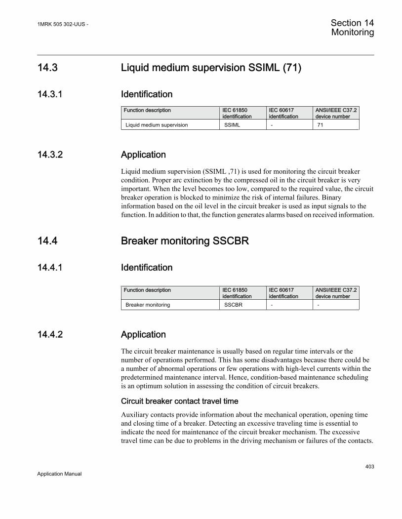
14.3 Liquid medium supervision SSIML (71)
14.3.1 IdentificationFunction description IEC 61850
identificationIEC 60617identification
ANSI/IEEE C37.2device number
Liquid medium supervision SSIML - 71
14.3.2 ApplicationLiquid medium supervision (SSIML ,71) is used for monitoring the circuit breakercondition. Proper arc extinction by the compressed oil in the circuit breaker is veryimportant. When the level becomes too low, compared to the required value, the circuitbreaker operation is blocked to minimize the risk of internal failures. Binaryinformation based on the oil level in the circuit breaker is used as input signals to thefunction. In addition to that, the function generates alarms based on received information.
14.4 Breaker monitoring SSCBR
14.4.1 Identification
Function description IEC 61850identification
IEC 60617identification
ANSI/IEEE C37.2device number
Breaker monitoring SSCBR - -
14.4.2 ApplicationThe circuit breaker maintenance is usually based on regular time intervals or thenumber of operations performed. This has some disadvantages because there could bea number of abnormal operations or few operations with high-level currents within thepredetermined maintenance interval. Hence, condition-based maintenance schedulingis an optimum solution in assessing the condition of circuit breakers.
Circuit breaker contact travel timeAuxiliary contacts provide information about the mechanical operation, opening timeand closing time of a breaker. Detecting an excessive traveling time is essential toindicate the need for maintenance of the circuit breaker mechanism. The excessivetravel time can be due to problems in the driving mechanism or failures of the contacts.
1MRK 505 302-UUS - Section 14Monitoring
403Application Manual

Circuit breaker statusMonitoring the breaker status ensures proper functioning of the features within theprotection relay such as breaker control, breaker failure and autoreclosing. The breakerstatus is monitored using breaker auxiliary contacts. The breaker status is indicated bythe binary outputs. These signals indicate whether the circuit breaker is in an open,closed or error state.
Remaining life of circuit breakerEvery time the breaker operates, the circuit breaker life reduces due to wear. The wearin a breaker depends on the interrupted current. For breaker maintenance orreplacement at the right time, the remaining life of the breaker must be estimated. Theremaining life of a breaker can be estimated using the maintenance curve provided bythe circuit breaker manufacturer.
Circuit breaker manufacturers provide the number of make-break operations possible atvarious interrupted currents. An example is shown in Figure175.
Section 14 1MRK 505 302-UUS -Monitoring
404Application Manual

Num
ber o
f mak
e-br
eak
oper
atio
ns (
n)
Interrupted current (kA)
P1
P2
100000
50000
20000
10000
2000
5000
1000
100
200
500
10
20
50
0.1 0.2 0.5 1 2 5 10 20 50 100
IEC12000623_1_en.vsdIEC12000623 V1 EN
Figure 175: An example for estimating the remaining life of a circuit breaker
Calculation for estimating the remaining life
The graph shows that there are 10000 possible operations at the rated operating currentand 900 operations at 10 kA and 50 operations at rated fault current. Therefore, if theinterrupted current is 10 kA, one operation is equivalent to 10000/900 = 11 operationsat the rated current. It is assumed that prior to tripping, the remaining life of a breakeris 10000 operations. Remaining life calculation for three different interrupted currentconditions is explained below.
• Breaker interrupts at and below the rated operating current, that is, 2 kA, theremaining life of the CB is decreased by 1 operation and therefore, 9999operations remaining at the rated operating current.
• Breaker interrupts between rated operating current and rated fault current, that is,10 kA, one operation at 10kA is equivalent to 10000/900 = 11 operations at the
1MRK 505 302-UUS - Section 14Monitoring
405Application Manual

rated current. The remaining life of the CB would be (10000 – 10) = 9989 at therated operating current after one operation at 10 kA.
• Breaker interrupts at and above rated fault current, that is, 50 kA, one operation at50 kA is equivalent to 10000/50 = 200 operations at the rated operating current.The remaining life of the CB would become (10000 – 200) = 9800 operations atthe rated operating current after one operation at 50 kA.
Accumulated energyMonitoring the contact erosion and interrupter wear has a direct influence on therequired maintenance frequency. Therefore, it is necessary to accurately estimate theerosion of the contacts and condition of interrupters using cumulative summation of Iy.The factor "y" depends on the type of circuit breaker. The energy values wereaccumulated using the current value and exponent factor for CB contact openingduration. When the next CB opening operation is started, the energy is accumulatedfrom the previous value. The accumulated energy value can be reset to initialaccumulation energy value by using the Reset accumulating energy input, RSTIPOW.
Circuit breaker operation cyclesRoutine breaker maintenance like lubricating breaker mechanism is based on thenumber of operations. A suitable threshold setting helps in preventive maintenance.This can also be used to indicate the requirement for oil sampling for dielectric testingin case of an oil circuit breaker.
Circuit breaker operation monitoringBy monitoring the activity of the number of operations, it is possible to calculate thenumber of days the breaker has been inactive. Long periods of inactivity degrade thereliability for the protection system.
Circuit breaker spring charge monitoringFor normal circuit breaker operation, the circuit breaker spring should be chargedwithin a specified time. Detecting a long spring charging time indicates the time forcircuit breaker maintenance. The last value of the spring charging time can be given asa service value.
Circuit breaker gas pressure indicationFor proper arc extinction by the compressed gas in the circuit breaker, the pressure ofthe gas must be adequate. Binary input available from the pressure sensor is based onthe pressure levels inside the arc chamber. When the pressure becomes too lowcompared to the required value, the circuit breaker operation is blocked.
Section 14 1MRK 505 302-UUS -Monitoring
406Application Manual

14.4.3 Setting guidelinesThe breaker monitoring function is used to monitor different parameters of the circuitbreaker. The breaker requires maintenance when the number of operations has reacheda predefined value. For proper functioning of the circuit breaker, it is also essential tomonitor the circuit breaker operation, spring charge indication or breaker wear, traveltime, number of operation cycles and accumulated energy during arc extinction.
14.4.3.1 Setting procedure on the IED
The parameters for breaker monitoring (SSCBR) can be set using the local HMI orProtection and Control Manager (PCM600).
Common base IED values for primary current (IBase), primary voltage (VBase) andprimary power (SBase) are set in Global base values for settings function GBASVAL.
GlobalBaseSel: It is used to select a GBASVAL function for reference of base values.
Operation: Enabled or Disabled.
IBase: Base phase current in primary A. This current is used as reference for currentsettings.
OpenTimeCorr: Correction factor for circuit breaker opening travel time.
CloseTimeCorr: Correction factor for circuit breaker closing travel time.
tTrOpenAlm: Setting of alarm level for opening travel time.
tTrCloseAlm: Setting of alarm level for closing travel time.
OperAlmLevel: Alarm limit for number of mechanical operations.
OperLOLevel: Lockout limit for number of mechanical operations.
CurrExponent: Current exponent setting for energy calculation. It varies for differenttypes of circuit breakers. This factor ranges from 0.5 to 3.0.
AccStopCurr: RMS current setting below which calculation of energy accumulationstops. It is given as a percentage of IBase.
ContTrCorr: Correction factor for time difference in auxiliary and main contacts'opening time.
AlmAccCurrPwr: Setting of alarm level for accumulated energy.
LOAccCurrPwr: Lockout limit setting for accumulated energy.
1MRK 505 302-UUS - Section 14Monitoring
407Application Manual

SpChAlmTime: Time delay for spring charging time alarm.
tDGasPresAlm: Time delay for gas pressure alarm.
tDGasPresLO: Time delay for gas pressure lockout.
DirCoef: Directional coefficient for circuit breaker life calculation.
RatedOperCurr: Rated operating current of the circuit breaker.
RatedFltCurr: Rated fault current of the circuit breaker.
OperNoRated: Number of operations possible at rated current.
OperNoFault: Number of operations possible at rated fault current.
CBLifeAlmLevel: Alarm level for circuit breaker remaining life.
AccSelCal: Selection between the method of calculation of accumulated energy.
OperTimeDelay: Time delay between change of status of trip output and start of maincontact separation.
14.5 Event function EVENT
14.5.1 IdentificationFunction description IEC 61850
identificationIEC 60617identification
ANSI/IEEE C37.2device number
Event function EVENTS00946 V1 EN
-
14.5.2 ApplicationWhen using a Substation Automation system with LON or SPA communication, time-tagged events can be sent at change or cyclically from the IED to the station level.These events are created from any available signal in the IED that is connected to theEvent function (EVENT). The event function block is used for remote communication.
Analog and double indication values are also transferred through EVENT function.
Section 14 1MRK 505 302-UUS -Monitoring
408Application Manual

14.5.3 Setting guidelinesThe parameters for the Event (EVENT) function are set via the local HMI or PCM600.
EventMask (Ch_1 - 16)The inputs can be set individually as:
• NoEvents• OnSet, at pick-up of the signal• OnReset, at drop-out of the signal• OnChange, at both pick-up and drop-out of the signal• AutoDetect
LONChannelMask or SPAChannelMaskDefinition of which part of the event function block that shall generate events:
• Disabled• Channel 1-8• Channel 9-16• Channel 1-16
MinRepIntVal (1 - 16)A time interval between cyclic events can be set individually for each input channel.This can be set between 0.0 s to 1000.0 s in steps of 0.1 s. It should normally be set to0, that is, no cyclic communication.
It is important to set the time interval for cyclic events in an optimizedway to minimize the load on the station bus.
14.6 Disturbance report DRPRDRE
14.6.1 IdentificationFunction description IEC 61850
identificationIEC 60617identification
ANSI/IEEE C37.2device number
Analog input signals A41RADR - -
Disturbance report DRPRDRE - -
Disturbance report A1RADR - -
Table continues on next page
1MRK 505 302-UUS - Section 14Monitoring
409Application Manual

Function description IEC 61850identification
IEC 60617identification
ANSI/IEEE C37.2device number
Disturbance report A2RADR - -
Disturbance report A3RADR - -
Disturbance report A4RADR - -
Disturbance report B1RBDR - -
Disturbance report B2RBDR - -
Disturbance report B3RBDR - -
Disturbance report B4RBDR - -
Disturbance report B5RBDR - -
Disturbance report B6RBDR - -
14.6.2 ApplicationTo get fast, complete and reliable information about disturbances in the primary and/orin the secondary system it is very important to gather information on fault currents,voltages and events. It is also important having a continuous event-logging to be ableto monitor in an overview perspective. These tasks are accomplished by thedisturbance report function DRPRDRE and facilitate a better understanding of thepower system behavior and related primary and secondary equipment during and aftera disturbance. An analysis of the recorded data provides valuable information that canbe used to explain a disturbance, basis for change of IED setting plan, improve existingequipment, and so on. This information can also be used in a longer perspective whenplanning for and designing new installations, that is, a disturbance recording could be apart of Functional Analysis (FA).
Disturbance report DRPRDRE, always included in the IED, acquires sampled data ofall selected analog and binary signals connected to the function blocks that is,
• maximum 30 external analog signals,• 10 internal derived analog signals, and• 96 binary signals.
Disturbance report function is a common name for several functions that is, Indications(IND), Event recorder (ER), Sequential of events (SOE), Trip value recorder (TVR),Disturbance recorder (DR).
Disturbance report function is characterized by great flexibility as far as configuration,starting conditions, recording times, and large storage capacity are concerned. Thus,disturbance report is not dependent on the operation of protective functions, and it canrecord disturbances that were not discovered by protective functions for one reason oranother. Disturbance report can be used as an advanced stand-alone disturbance recorder.
Section 14 1MRK 505 302-UUS -Monitoring
410Application Manual
Every disturbance report recording is saved in the IED. The same applies to all events,which are continuously saved in a ring-buffer. Local HMI can be used to getinformation about the recordings, and the disturbance report files may be uploaded inthe PCM600 using the Disturbance handling tool, for report reading or further analysis(using WaveWin, that can be found on the PCM600 installation CD). The user can alsoupload disturbance report files using FTP or MMS (over 61850–8–1) clients.
If the IED is connected to a station bus (IEC 61850-8-1), the disturbance recorder(record made and fault number) and the fault locator information are available asGOOSE or Report Control data. The same information is obtainable ifIEC60870-5-103 is used.
14.6.3 Setting guidelinesThe setting parameters for the Disturbance report function DRPRDRE are set via thelocal HMI or PCM600.
It is possible to handle up to 40 analog and 96 binary signals, either internal signals orsignals coming from external inputs. The binary signals are identical in all functionsthat is, Disturbance recorder (DR), Event recorder (ER), Indication (IND), Trip valuerecorder (TVR) and Sequential of events (SOE) function.
User-defined names of binary and analog input signals is set using PCM600. Theanalog and binary signals appear with their user-defined names. The name is used in allrelated functions (Disturbance recorder (DR), Event recorder (ER), Indication (IND),Trip value recorder (TVR) and Sequential of events (SOE)).
Figure 176 shows the relations between Disturbance report, included functions andfunction blocks. Sequential of events (SOE), Event recorder (ER) and Indication (IND)uses information from the binary input function blocks (BxRBDR). Trip value recorder(TVR) uses analog information from the analog input function blocks (AxRADR),.Disturbance report function acquires information from both AxRADR and BxRBDR.
Figure 176: Disturbance report functions and related function blocks
For Disturbance report function there are a number of settings which also influencesthe sub-functions.
Three LED indications placed above the LCD screen makes it possible to get quickstatus information about the IED.
Green LED:
Steady light In Service
Flashing light Internal failure
Dark No power supply
Table continues on next page
1MRK 505 302-UUS - Section 14Monitoring
411Application Manual
Yellow LED:
Steady light A Disturbance Report is triggered
Flashing light The IED is in test mode
Red LED:
Steady light Triggered on binary signal N with SetLEDN = Enabled
OperationThe operation of Disturbance report function DRPRDRE has to be set Enabled orDisabled. If Disabled is selected, note that no disturbance report is registered, and nonesub-function will operate (the only general parameter that influences Sequential ofevents (SOE)).
Operation = Disabled:
• Disturbance reports are not stored.• LED information (yellow - pickup, red - trip) is not stored or changed.
Operation = Enabled:
• Disturbance reports are stored, disturbance data can be read from the local HMIand from a PC using PCM600.
• LED information (yellow - pickup, red - trip) is stored.
Every recording will get a number (0 to 999) which is used as identifier (local HMI,disturbance handling tool and IEC 61850). An alternative recording identification isdate, time and sequence number. The sequence number is automatically increased byone for each new recording and is reset to zero at midnight. The maximum number ofrecordings stored in the IED is 100. The oldest recording will be overwritten when anew recording arrives (FIFO).
To be able to delete disturbance records, Operation parameter has to beEnabled.
The maximum number of recordings depend on each recordings totalrecording time. Long recording time will reduce the number ofrecordings to less than 100.
Section 14 1MRK 505 302-UUS -Monitoring
412Application Manual

The IED flash disk should NOT be used to store any user files. Thismight cause disturbance recordings to be deleted due to lack of disk space.
14.6.3.1 Recording times
Prefault recording time (PreFaultRecT) is the recording time before the starting pointof the disturbance. The setting should be at least 0.1 s to ensure enough samples for theestimation of pre-fault values in the Trip value recorder (TVR) function.
Postfault recording time (PostFaultRecT) is the maximum recording time after thedisappearance of the trig-signal (does not influence the Trip value recorder (TVR)function).
Recording time limit (TimeLimit) is the maximum recording time after trig. Theparameter limits the recording time if some trigging condition (fault-time) is very longor permanently set (does not influence the Trip value recorder (TVR) function).
Post retrigger (PostRetrig) can be set to Enabled or Disabled. Makes it possible tochoose performance of Disturbance report function if a new trig signal appears in thepost-fault window.
PostRetrig = Disabled
The function is insensitive for new trig signals during post fault time.
PostRetrig = Enabled
The function completes current report and starts a new complete report that is, thelatter will include:
• new pre-fault- and fault-time (which will overlap previous report)• events and indications might be saved in the previous report too, due to overlap• new trip value calculations if installed, in operation and started
Operation in test modeIf the IED is in test mode and OpModeTest = Disabled. Disturbance report functiondoes not save any recordings and no LED information is displayed.
If the IED is in test mode and OpModeTest = Enabled. Disturbance report functionworks in normal mode and the status is indicated in the saved recording.
1MRK 505 302-UUS - Section 14Monitoring
413Application Manual

14.6.3.2 Binary input signals
Up to 96 binary signals can be selected among internal logical and binary input signals.The configuration tool is used to configure the signals.
For each of the 96 signals, it is also possible to select if the signal is to be used as atrigger for the start of the Disturbance report and if the trigger should be activated onpositive (1) or negative (0) slope.
TrigDRN: Disturbance report may trig for binary input N (Enabled) or not (Disabled).
TrigLevelN: Trig on positive (Trig on 1) or negative (Trig on 0) slope for binary input N.
Func103N: Function type number (0-255) for binary input N according toIEC-60870-5-103, that is, 128: Distance protection, 160: overcurrent protection, 176:transformer differential protection and 192: line differential protection.
Info103N: Information number (0-255) for binary input N according toIEC-60870-5-103, that is, 69-71: Trip L1-L3, 78-83: Zone 1-6.
See also description in the chapter IEC 60870-5-103.
14.6.3.3 Analog input signals
Up to 40 analog signals can be selected among internal analog and analog inputsignals. PCM600 is used to configure the signals.
For retrieving remote data from LDCM module, the Disturbance reportfunction should not be connected to a 3 ms SMAI function block if thisis the only intended use for the remote data.
The analog trigger of Disturbance report is not affected if analog input M is to beincluded in the disturbance recording or not (OperationM = Enabled/Disabled).
If OperationM = Disabled, no waveform (samples) will be recorded and reported ingraph. However, Trip value, pre-fault and fault value will be recorded and reported.The input channel can still be used to trig the disturbance recorder.
If OperationM = Enabled, waveform (samples) will also be recorded and reported ingraph.
NomValueM: Nominal value for input M.
OverTrigOpM, UnderTrigOpM: Over or Under trig operation, Disturbance report maytrig for high/low level of analog input M (Enabled) or not (Disabled).
Section 14 1MRK 505 302-UUS -Monitoring
414Application Manual
OverTrigLeM, UnderTrigLeM: Over or under trig level, Trig high/low level relativenominal value for analog input M in percent of nominal value.
14.6.3.4 Sub-function parameters
All functions are in operation as long as Disturbance report is in operation.
IndicationsIndicationMaN: Indication mask for binary input N. If set (Show), a status change ofthat particular input, will be fetched and shown in the disturbance summary on localHMI. If not set (Hide), status change will not be indicated.
SetLEDN: Set red LED on local HMI in front of the IED if binary input N changes status.
Disturbance recorderOperationM: Analog channel M is to be recorded by the disturbance recorder(Enabled) or not (Disabled).
If OperationM = Disabled, no waveform (samples) will be recorded and reported ingraph. However, Trip value, pre-fault and fault value will be recorded and reported.The input channel can still be used to trig the disturbance recorder.
If OperationM = Enabled, waveform (samples) will also be recorded and reported ingraph.
Event recorderEvent recorder (ER) function has no dedicated parameters.
Trip value recorderZeroAngleRef: The parameter defines which analog signal that will be used as phaseangle reference for all other analog input signals. This signal will also be used forfrequency measurement and the measured frequency is used when calculating tripvalues. It is suggested to point out a sampled voltage input signal, for example, a lineor busbar phase voltage (channel 1-30).
Sequential of eventsfunction has no dedicated parameters.
14.6.3.5 Consideration
The density of recording equipment in power systems is increasing, since the numberof modern IEDs, where recorders are included, is increasing. This leads to a vastnumber of recordings at every single disturbance and a lot of information has to behandled if the recording functions do not have proper settings. The goal is to optimize
1MRK 505 302-UUS - Section 14Monitoring
415Application Manual
the settings in each IED to be able to capture just valuable disturbances and tomaximize the number that is possible to save in the IED.
The recording time should not be longer than necessary (PostFaultrecT and TimeLimit).
• Should the function record faults only for the protected object or cover more?• How long is the longest expected fault clearing time?• Is it necessary to include reclosure in the recording or should a persistent fault
generate a second recording (PostRetrig)?
Minimize the number of recordings:
• Binary signals: Use only relevant signals to start the recording that is, protectiontrip, carrier receive and/or pickup signals.
• Analog signals: The level triggering should be used with great care, sinceunfortunate settings will cause enormously number of recordings. If neverthelessanalog input triggering is used, chose settings by a sufficient margin from normaloperation values. Phase voltages are not recommended for trigging.
Remember that values of parameters set elsewhere are linked to the information on areport. Such parameters are, for example, station and object identifiers, CT and VT ratios.
14.7 Logical signal status report BINSTATREP
14.7.1 IdentificationFunction description IEC 61850
identificationIEC 60617identification
ANSI/IEEE C37.2device number
Logical signal status report BINSTATREP - -
14.7.2 ApplicationThe Logical signal status report (BINSTATREP) function makes it possible for a SPAmaster to poll signals from various other function blocks.
BINSTATREP has 16 inputs and 16 outputs. The output status follows the inputs andcan be read from the local HMI or via SPA communication.
When an input is set, the respective output is set for a user defined time. If the inputsignal remains set for a longer period, the output will remain set until the input signalresets.
Section 14 1MRK 505 302-UUS -Monitoring
416Application Manual
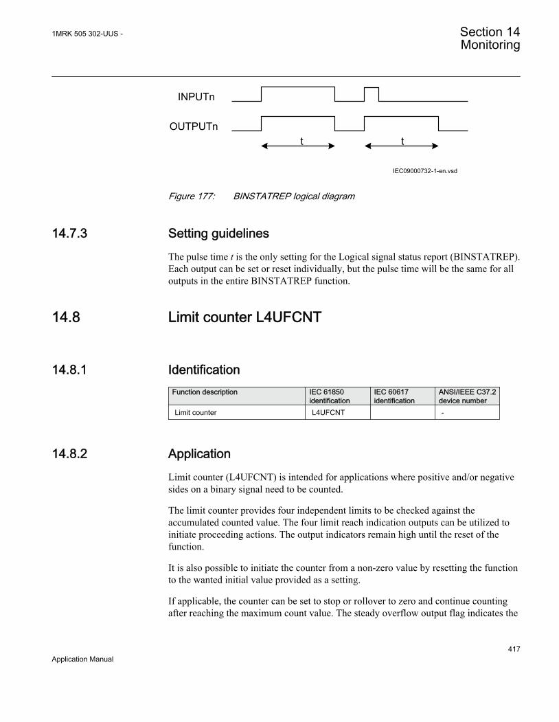
t t
INPUTn
OUTPUTn
IEC09000732-1-en.vsdIEC09000732 V1 EN
Figure 177: BINSTATREP logical diagram
14.7.3 Setting guidelinesThe pulse time t is the only setting for the Logical signal status report (BINSTATREP).Each output can be set or reset individually, but the pulse time will be the same for alloutputs in the entire BINSTATREP function.
14.8 Limit counter L4UFCNT
14.8.1 IdentificationFunction description IEC 61850
identificationIEC 60617identification
ANSI/IEEE C37.2device number
Limit counter L4UFCNT -
14.8.2 ApplicationLimit counter (L4UFCNT) is intended for applications where positive and/or negativesides on a binary signal need to be counted.
The limit counter provides four independent limits to be checked against theaccumulated counted value. The four limit reach indication outputs can be utilized toinitiate proceeding actions. The output indicators remain high until the reset of thefunction.
It is also possible to initiate the counter from a non-zero value by resetting the functionto the wanted initial value provided as a setting.
If applicable, the counter can be set to stop or rollover to zero and continue countingafter reaching the maximum count value. The steady overflow output flag indicates the
1MRK 505 302-UUS - Section 14Monitoring
417Application Manual

next count after reaching the maximum count value. It is also possible to set thecounter to rollover and indicate the overflow as a pulse, which lasts up to the firstcount after rolling over to zero. In this case, periodic pulses will be generated atmultiple overflow of the function.
14.8.2.1 Setting guidelines
The parameters for Limit counter L4UFCNT are set via the local HMI or PCM600.
Section 14 1MRK 505 302-UUS -Monitoring
418Application Manual
Section 15 Metering
15.1 Pulse-counter logic PCFCNT
15.1.1 IdentificationFunction description IEC 61850
identificationIEC 60617identification
ANSI/IEEE C37.2device number
Pulse-counter logic PCFCNT
S00947 V1 EN
-
15.1.2 ApplicationPulse-counter logic (PCFCNT) function counts externally generated binary pulses, forinstance pulses coming from an external energy meter, for calculation of energyconsumption values. The pulses are captured by the binary input module (BIM), andread by the PCFCNT function. The number of pulses in the counter is then reported viathe station bus to the substation automation system or read via the station monitoringsystem as a service value. When using IEC 61850–8–1, a scaled service value isavailable over the station bus.
The normal use for this function is the counting of energy pulses from external energymeters. An optional number of inputs from an arbitrary input module in IED can beused for this purpose with a frequency of up to 40 Hz. The pulse-counter logicPCFCNT can also be used as a general purpose counter.
15.1.3 Setting guidelinesFrom PCM600, these parameters can be set individually for each pulse counter:
• Operation: Disabled/Enabled• tReporting: 0-3600s• EventMask: NoEvents/ReportEvents
1MRK 505 302-UUS - Section 15Metering
419Application Manual

The configuration of the inputs and outputs of the pulse counter-logic PCFCNTfunction block is made with PCM600.
On the Binary Input Module, the debounce filter time is fixed to 5 ms, that is, thecounter suppresses pulses with a pulse length less than 5 ms. The input oscillationblocking frequency is preset to 40 Hz. That means that the counter finds the inputoscillating if the input frequency is greater than 40 Hz. The oscillation suppression isreleased at 30 Hz. The values for blocking/release of the oscillation can be changed inthe local HMI and PCM600 under Main menu/Settings/General settings/I/O-modules.
The debounce time should be set to the same value for all channels onthe board.
The setting is common for all input channels on a Binary Input Module,that is, if changes of the limits are made for inputs not connected to thepulse counter, the setting also influences the inputs on the same boardused for pulse counting.
15.2 Function for energy calculation and demand handlingETPMMTR
15.2.1 IdentificationFunction description IEC 61850
identificationIEC 60617identification
ANSI/IEEE C37.2device number
Function for energy calculation anddemand handling
ETPMMTR W_Varh -
15.2.2 ApplicationEnergy calculation and demand handling function (ETPMMTR) is intended forstatistics of the forward and reverse active and reactive energy. It has a high accuracybasically given by the measurements function (CVMMXN). This function has a sitecalibration possibility to further increase the total accuracy.
Section 15 1MRK 505 302-UUS -Metering
420Application Manual

The function is connected to the instantaneous outputs of (CVMMXN) as shown infigure 178.
ETPMMTR
PQSTARTACCSTOPACCRSTACCRSTDMD
ACCINPRGEAFPULSEEARPULSEERFPULSEERRPULSE
EAFALMEARALMERFALMERRALMEAFACCEARACCERFACCERRACC
MAXPAFDMAXPARDMAXPRFDMAXPRRD
IEC13000184-1-en.vsd IEC13000190 V1 EN
Figure 178: Connection of energy calculation and demand handling functionETPMMTR to the measurements function (CVMMXN)
The energy values can be read through communication in MWh and MVArh inmonitoring tool of PCM600 and/or alternatively the values can be presented on thelocal HMI. The local HMI graphical display is configured with PCM600 GraphicalDisplay Editor tool (GDE) with a measuring value which is selected to the active andreactive component as preferred. Also all Accumulated Active Forward, ActiveReverse, Reactive Forward and Reactive Reverse energy values can be presented.
Maximum demand values are presented in MWh or MVArh in the same way.
Alternatively, the energy values can be presented with use of the pulse countersfunction (PCGGIO). The output energy values are scaled with the pulse output settingvalues EAFAccPlsQty, EARAccPlsQty, ERFAccPlsQty and ERVAccPlsQty of theenergy metering function and then the pulse counter can be set-up to present the correctvalues by scaling in this function. Pulse counter values can then be presented on thelocal HMI in the same way and/or sent to the SA (Substation Automation) systemthrough communication where the total energy then is calculated by summation of theenergy pulses. This principle is good for very high values of energy as the saturation ofnumbers else will limit energy integration to about one year with 50 kV and 3000 A.After that the accumulation will start on zero again.
15.2.3 Setting guidelinesThe parameters are set via the local HMI or PCM600.
The following settings can be done for the energy calculation and demand handlingfunction ETPMMTR:
1MRK 505 302-UUS - Section 15Metering
421Application Manual

GlobalBaseSel: Selects the global base value group used by the function to define(IBase), (VBase) and (SBase).
Operation: Disabled/Enabled
EnaAcc: Disabled/Enabled is used to switch the accumulation of energy on and off.
tEnergy: Time interval when energy is measured.
tEnergyOnPls: gives the pulse length ON time of the pulse. It should be at least 100 mswhen connected to the Pulse counter function block. Typical value can be 100 ms.
tEnergyOffPls: gives the OFF time between pulses. Typical value can be 100 ms.
EAFAccPlsQty and EARAccPlsQty: gives the MWh value in each pulse. It should beselected together with the setting of the Pulse counter (PCGGIO) settings to give thecorrect total pulse value.
ERFAccPlsQty and ERVAccPlsQty : gives the MVArh value in each pulse. It should beselected together with the setting of the Pulse counter (PCGGIO) settings to give thecorrect total pulse value.
For the advanced user there are a number of settings for direction, zero clamping, maxlimit, and so on. Normally, the default values are suitable for these parameters.
Section 15 1MRK 505 302-UUS -Metering
422Application Manual
Section 16 Station communication
16.1 670 series protocols
Each IED is provided with a communication interface, enabling it to connect to one ormany substation level systems or equipment, either on the Substation Automation (SA)bus or Substation Monitoring (SM) bus.
Following communication protocols are available:
• IEC 61850-8-1 communication protocol• LON communication protocol• SPA or IEC 60870-5-103 communication protocol• DNP3.0 communication protocol
Theoretically, several protocols can be combined in the same IED.
16.2 IEC 61850-8-1 communication protocol
16.2.1 Application IEC 61850-8-1IEC 61850-8-1 communication protocol allows vertical communication to HSI clientsand allows horizontal communication between two or more intelligent electronicdevices (IEDs) from one or several vendors to exchange information and to use it inthe performance of their functions and for correct co-operation.
GOOSE (Generic Object Oriented Substation Event), which is a part of IEC 61850–8–1 standard, allows the IEDs to communicate state and control information amongstthemselves, using a publish-subscribe mechanism. That is, upon detecting an event, theIED(s) use a multi-cast transmission to notify those devices that have registered toreceive the data. An IED can, by publishing a GOOSE message, report its status. It canalso request a control action to be directed at any device in the network.
Figure 179 shows the topology of an IEC 61850–8–1 configuration. IEC 61850–8–1specifies only the interface to the substation LAN. The LAN itself is left to the systemintegrator.
1MRK 505 302-UUS - Section 16Station communication
423Application Manual
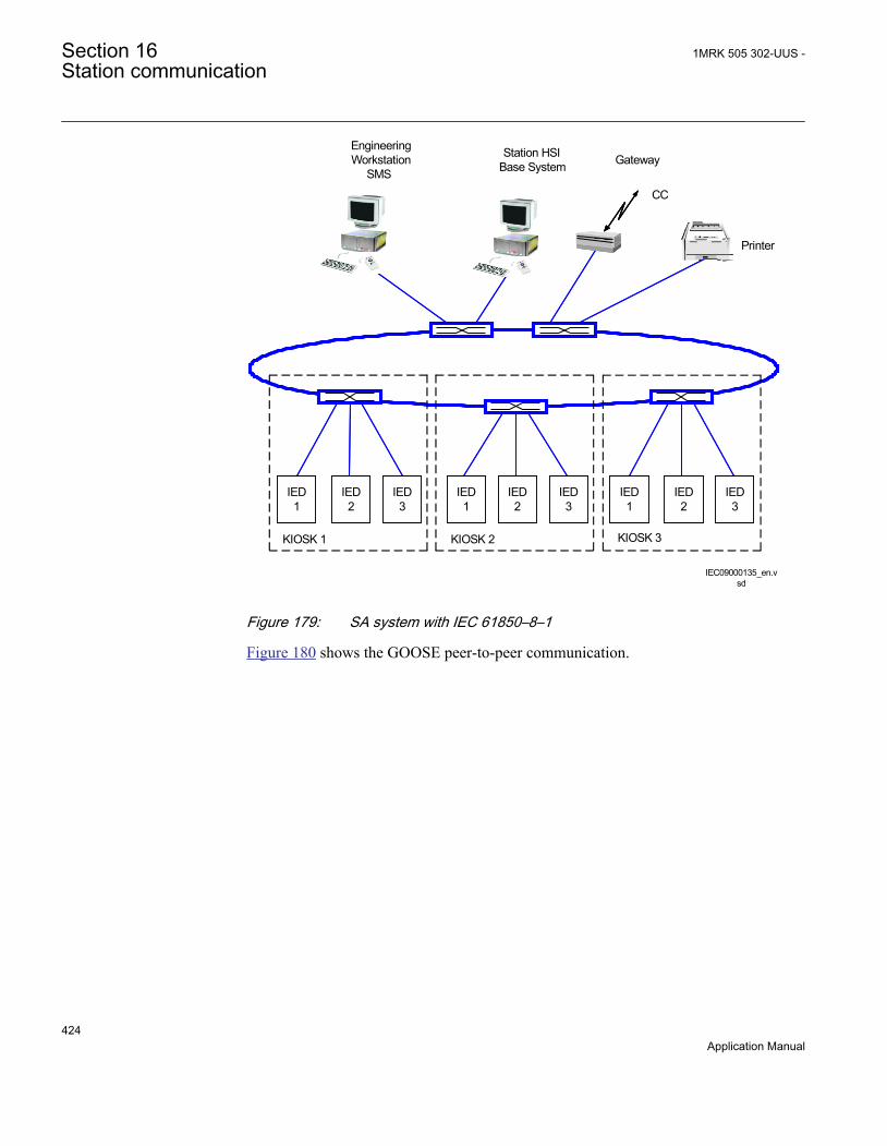
KIOSK 2 KIOSK 3
Station HSIBase System
EngineeringWorkstation
SMSGateway
Printer
CC
IEC09000135_en.vsd
KIOSK 1
IED 1
IED 2
IED 3
IED 1
IED 2
IED 3
IED 1
IED 2
IED 3
IEC09000135 V1 EN
Figure 179: SA system with IEC 61850–8–1
Figure 180 shows the GOOSE peer-to-peer communication.
Section 16 1MRK 505 302-UUS -Station communication
424Application Manual

Control Protection Control ProtectionControl and protection
GOOSE
en05000734.vsd
Station HSIMicroSCADA
Gateway
IEDA
IEDA
IEDA
IEDA
IEDA
IEC05000734 V1 EN
Figure 180: Example of a broadcasted GOOSE message
16.2.2 Horizontal communication via GOOSE for interlockingGOOSEINTLKRCV
Table 42: GOOSEINTLKRCV Non group settings (basic)
Name Values (Range) Unit Step Default DescriptionOperation Disabled
Enabled- - Disabled Operation Disabled/Enabled
16.2.3 Setting guidelinesThere are two settings related to the IEC 61850–8–1 protocol:
Operation User can set IEC 61850 communication to Enabled or Disabled.
GOOSE has to be set to the Ethernet link where GOOSE traffic shall be send and received.
16.2.4 Generic communication function for Single Point indicationSPGAPC, SP16GAPC
1MRK 505 302-UUS - Section 16Station communication
425Application Manual

16.2.4.1 Application
Generic communication function for Measured Value (SPGAPC) function is used tosend one single logical output to other systems or equipment in the substation. It hasone visible input, that should be connected in ACT tool.
16.2.4.2 Setting guidelines
There are no settings available for the user for SPGAPC. However, PCM600 must beused to get the signals sent by SPGAPC.
16.2.5 Generic communication function for Measured Value MVGAPC
16.2.5.1 Application
Generic communication function for Measured Value MVGAPC function is used tosend the instantaneous value of an analog signal to other systems or equipment in thesubstation. It can also be used inside the same IED, to attach a RANGE aspect to ananalog value and to permit measurement supervision on that value.
16.2.5.2 Setting guidelines
The settings available for Generic communication function for Measured Value(MVGAPC) function allows the user to choose a deadband and a zero deadband for themonitored signal. Values within the zero deadband are considered as zero.
The high and low limit settings provides limits for the high-high-, high, normal, lowand low-low ranges of the measured value. The actual range of the measured value isshown on the range output of MVGAPC function block. When a Measured valueexpander block (RANGE_XP) is connected to the range output, the logical outputs ofthe RANGE_XP are changed accordingly.
16.2.6 IEC 61850-8-1 redundant station bus communication
16.2.6.1 Identification
Function description LHMI identification IEC 61850identification
IEC 60617identification
ANSI/IEEE C37.2device number
Parallel RedundancyProtocol Status
PRPSTATUS RCHLCCH - -
Duo driverconfiguration
PRP - - -
Section 16 1MRK 505 302-UUS -Station communication
426Application Manual

16.2.6.2 Application
Parallel redundancy protocol status (PRPSTATUS) together with Duo driverconfiguration (DUODRV) are used to supervise and assure redundant Ethernetcommunication over two channels. This will secure data transfer even though onecommunication channel might not be available for some reason. TogetherPRPSTATUS and DUODRV provide redundant communication over station busrunning IEC 61850-8-1 protocol. The redundant communication use both port AB andCD on OEM module.
1MRK 505 302-UUS - Section 16Station communication
427Application Manual

Duo
Switch A Switch B1 2
Redundancy Supervision
Station Control System
DataData
DataData
IEC09000758-2-en.vsd
IED Configuration
DUODRV PRPSTATUS
1 2
OEM
AB CD
IEC09000758 V2 EN
Figure 181: Redundant station bus
Section 16 1MRK 505 302-UUS -Station communication
428Application Manual

16.2.6.3 Setting guidelines
Redundant communication (DUODRV) is configured in the local HMI under Mainmenu/Settings/General settings/Communication/Ethernet configuration/RearOEM - Redundant PRP
The settings can then be viewed, but not set, in the Parameter Setting tool in PCM600under Main menu/IED Configuration/Communication/Ethernet configuration/DUODRV:
Operation: The redundant communication will be activated when this parameter is setto On.After confirmation the IED will restart and the setting alternatives Rear OEM -Port AB and CD will not be further displayed in the local HMI. The ETHLANAB andETHLANCD in the Parameter Setting Tool are irrelevant when the redundantcommunication is activated, only DUODRV IPAdress and IPMask are valid.
1MRK 505 302-UUS - Section 16Station communication
429Application Manual

IEC10000057-1-en.vsd
IEC10000057 V1 EN
Figure 182: PST screen: DUODRV Operation is set to On, which affect Rear OEM- Port AB and CD which are both set to Duo
Section 16 1MRK 505 302-UUS -Station communication
430Application Manual

16.3 LON communication protocol
16.3.1 Application
Control Center
IED IEDIED
Gateway
Star couplerRER 111
Station HSIMicroSCADA
IEC05000663-1-en.vsdIEC05000663 V2 EN
Figure 183: Example of LON communication structure for a substation automationsystem
An optical network can be used within the substation automation system. This enablescommunication with the IEDs in the 670 series through the LON bus from theoperator’s workplace, from the control center and also from other IEDs via bay-to-bayhorizontal communication.
The fibre optic LON bus is implemented using either glass core or plastic core fibreoptic cables.
Table 43: Specification of the fibre optic connectors
Glass fibre Plastic fibreCable connector ST-connector snap-in connector
Cable diameter 62.5/125 m 1 mm
Max. cable length 1000 m 10 m
Wavelength 820-900 nm 660 nm
Transmitted power -13 dBm (HFBR-1414) -13 dBm (HFBR-1521)
Receiver sensitivity -24 dBm (HFBR-2412) -20 dBm (HFBR-2521)
1MRK 505 302-UUS - Section 16Station communication
431Application Manual
The LON ProtocolThe LON protocol is specified in the LonTalkProtocol Specification Version 3 fromEchelon Corporation. This protocol is designed for communication in control networksand is a peer-to-peer protocol where all the devices connected to the network cancommunicate with each other directly. For more information of the bay-to-baycommunication, refer to the section Multiple command function.
Hardware and software modulesThe hardware needed for applying LON communication depends on the application,but one very central unit needed is the LON Star Coupler and optical fibres connectingthe star coupler to the IEDs. To interface the IEDs from MicroSCADA, the applicationlibrary LIB670 is required.
The HV Control 670 software module is included in the LIB520 high-voltage processpackage, which is a part of the Application Software Library within MicroSCADAapplications.
The HV Control 670 software module is used for control functions in IEDs in the 670series. This module contains the process picture, dialogues and a tool to generate theprocess database for the control application in MicroSCADA.
Use the LON Network Tool (LNT) to set the LON communication. This is a softwaretool applied as one node on the LON bus. To communicate via LON, the IEDs need toknow
• The node addresses of the other connected IEDs.• The network variable selectors to be used.
This is organized by LNT.
The node address is transferred to LNT via the local HMI by setting the parameterServicePinMsg = Yes. The node address is sent to LNT via the LON bus, or LNT canscan the network for new nodes.
The communication speed of the LON bus is set to the default of 1.25 Mbit/s. This canbe changed by LNT.
16.4 SPA communication protocol
16.4.1 ApplicationSPA communication protocol as an alternative to IEC 60870-5-103. The samecommunication port as for IEC 60870-5-103 is used.
Section 16 1MRK 505 302-UUS -Station communication
432Application Manual

When communicating with a PC connected to the utility substation LAN, via WANand the utility office LAN, as shown in figure 184, and using the rear Ethernet port onthe optical Ethernet module (OEM), the only hardware required for a stationmonitoring system is:
• Optical fibres from the IED to the utility substation LAN.• PC connected to the utility office LAN.
IED IEDIED
Substation LAN
ANSI05000715-3-en.vsd
Remote monitoring
Utility LAN
WAN
ANSI05000715 V3 EN
Figure 184: SPA communication structure for a remote monitoring system via asubstation LAN, WAN and utility LAN
The SPA communication is mainly used for the Station Monitoring System. It caninclude different IEDs with remote communication possibilities. Connection to acomputer (PC) can be made directly (if the PC is located in the substation) or bytelephone modem through a telephone network with ITU (former CCITT)characteristics or via a LAN/WAN connection.
glass <1000 m according to optical budget
plastic <20 m (inside cubicle) according to optical budget
FunctionalityThe SPA protocol V2.5 is an ASCII-based protocol for serial communication. Thecommunication is based on a master-slave principle, where the IED is a slave and thePC is the master. Only one master can be applied on each fibre optic loop. A programis required in the master computer for interpretation of the SPA-bus codes and fortranslation of the data that should be sent to the IED.
For the specification of the SPA protocol V2.5, refer to SPA-bus CommunicationProtocol V2.5.
1MRK 505 302-UUS - Section 16Station communication
433Application Manual
16.4.2 Setting guidelinesThe setting parameters for the SPA communication are set via the local HMI.
SPA, IEC 60870-5-103 and DNP3 uses the same rear communication port. Set theparameter Operation, under Main menu /Settings /General settings /Communication /SLM configuration /Rear optical SPA-IEC-DNP port /Protocolselection to the selected protocol.
When the communication protocols have been selected, the IED is automaticallyrestarted.
The most important settings in the IED for SPA communication are the slave numberand baud rate (communication speed). These settings are absolutely essential for allcommunication contact to the IED.
These settings can only be done on the local HMI for rear channel communication andfor front channel communication.
The slave number can be set to any value from 1 to 899, as long as the slave number isunique within the used SPA loop.
The baud rate, which is the communication speed, can be set to between 300 and38400 baud. Refer to technical data to determine the rated communication speed forthe selected communication interfaces. The baud rate should be the same for the wholestation, although different baud rates in a loop are possible. If different baud rates inthe same fibre optical loop or RS485 network are used, consider this when making thecommunication setup in the communication master, the PC.
For local fibre optic communication, 19200 or 38400 baud is the normal setting. Iftelephone communication is used, the communication speed depends on the quality ofthe connection and on the type of modem used. But remember that the IED does notadapt its speed to the actual communication conditions, because the speed is set on thelocal HMI.
Section 16 1MRK 505 302-UUS -Station communication
434Application Manual

16.5 IEC 60870-5-103 communication protocol
16.5.1 Application
TCP/IP
Control Center
IED IEDIED
Gateway
Star coupler
Station HSI
ANSI05000660-4-en.vsdANSI05000660 V4 EN
Figure 185: Example of IEC 60870-5-103 communication structure for a substationautomation system
IEC 60870-5-103 communication protocol is mainly used when a protection IEDcommunicates with a third party control or monitoring system. This system must havesoftware that can interpret the IEC 60870-5-103 communication messages.
When communicating locally in the station using a Personal Computer (PC) or aRemote Terminal Unit (RTU) connected to the Communication and processingmodule, the only hardware needed is optical fibres and an opto/electrical converter forthe PC/RTU, or a RS-485 connection depending on the used IED communicationinterface.
FunctionalityIEC 60870-5-103 is an unbalanced (master-slave) protocol for coded-bit serialcommunication exchanging information with a control system. In IEC terminology aprimary station is a master and a secondary station is a slave. The communication isbased on a point-to-point principle. The master must have software that can interpretthe IEC 60870-5-103 communication messages. For detailed information about IEC
1MRK 505 302-UUS - Section 16Station communication
435Application Manual

60870-5-103, refer to IEC60870 standard part 5: Transmission protocols, and to thesection 103, Companion standard for the informative interface of protection equipment.
Design
GeneralThe protocol implementation consists of the following functions:
• Event handling• Report of analog service values (measurands)• Fault location• Command handling
• Autorecloser ON/OFF• Teleprotection ON/OFF• Protection ON/OFF• LED reset• Characteristics 1 - 4 (Setting groups)
• File transfer (disturbance files)• Time synchronization
HardwareWhen communicating locally with a Personal Computer (PC) or a Remote TerminalUnit (RTU) in the station, using the SPA/IEC port, the only hardware needed is:·Optical fibres, glass/plastic· Opto/electrical converter for the PC/RTU· PC/RTU
CommandsThe commands defined in the IEC 60870-5-103 protocol are represented in a dedicatedfunction blocks. These blocks have output signals for all available commandsaccording to the protocol.
• IED commands in control direction
Function block with defined IED functions in control direction, I103IEDCMD. Thisblock use PARAMETR as FUNCTION TYPE, and INFORMATION NUMBERparameter is defined for each output signal.
• Function commands in control direction
Function block with pre defined functions in control direction, I103CMD. This blockincludes the FUNCTION TYPE parameter, and the INFORMATION NUMBERparameter is defined for each output signal.
• Function commands in control direction
Section 16 1MRK 505 302-UUS -Station communication
436Application Manual

Function block with user defined functions in control direction, I103UserCMD. Thesefunction blocks include the FUNCTION TYPE parameter for each block in the privaterange, and the INFORMATION NUMBER parameter for each output signal.
StatusThe events created in the IED available for the IEC 60870-5-103 protocol are based onthe:
• IED status indication in monitor direction
Function block with defined IED functions in monitor direction, I103IED. This blockuse PARAMETER as FUNCTION TYPE, and INFORMATION NUMBER parameteris defined for each input signal.
• Function status indication in monitor direction, user-defined
Function blocks with user defined input signals in monitor direction, I103UserDef.These function blocks include the FUNCTION TYPE parameter for each block in theprivate range, and the INFORMATION NUMBER parameter for each input signal.
• Supervision indications in monitor direction
Function block with defined functions for supervision indications in monitor direction,I103Superv. This block includes the FUNCTION TYPE parameter, and theINFORMATION NUMBER parameter is defined for each output signal.
• Ground fault indications in monitor direction
Function block with defined functions for ground fault indications in monitor direction,I103EF. This block includes the FUNCTION TYPE parameter, and theINFORMATION NUMBER parameter is defined for each output signal.
• Fault indications in monitor direction, type 1
Function block with defined functions for fault indications in monitor direction,I103FltDis. This block includes the FUNCTION TYPE parameter, and theINFORMATION NUMBER parameter is defined for each input signal. This block issuitable for distance protection function.
• Fault indications in monitor direction, type 2
Function block with defined functions for fault indications in monitor direction,I103FltStd. This block includes the FUNCTION TYPE parameter, and theINFORMATION NUMBER parameter is defined for each input signal.
1MRK 505 302-UUS - Section 16Station communication
437Application Manual

This block is suitable for line differential, transformer differential, over-current andground-fault protection functions.
• Autorecloser indications in monitor direction
Function block with defined functions for autorecloser indications in monitor direction,I103AR. This block includes the FUNCTION TYPE parameter, and theINFORMATION NUMBER parameter is defined for each output signal.
MeasurandsThe measurands can be included as type 3.1, 3.2, 3.3, 3.4 and type 9 according to thestandard.
• Measurands in public range
Function block that reports all valid measuring types depending on connected signals,I103Meas.
• Measurands in private range
Function blocks with user defined input measurands in monitor direction,I103MeasUsr. These function blocks include the FUNCTION TYPE parameter foreach block in the private range, and the INFORMATION NUMBER parameter foreach block.
Fault locationThe fault location is expressed in reactive ohms. In relation to the line length inreactive ohms, it gives the distance to the fault in percent. The data is available andreported when the fault locator function is included in the IED.
Disturbance recordings
• The transfer functionality is based on the Disturbance recorder function. Theanalog and binary signals recorded will be reported to the master by polling. Theeight last disturbances that are recorded are available for transfer to the master. Afile that has been transferred and acknowledged by the master cannot betransferred again.
• The binary signals that are included in the disturbance recorder are those that areconnected to the disturbance function blocks B1RBDR to B6RBDR. Thesefunction blocks include the function type and the information number for eachsignal. For more information on the description of the Disturbance report in theTechnical reference manual. The analog channels, that are reported, are thoseconnected to the disturbance function blocks A1RADR to A4RADR. The eightfirst ones belong to the public range and the remaining ones to the private range.
Section 16 1MRK 505 302-UUS -Station communication
438Application Manual

Settings
Settings for RS485 and optical serial communication
General settingsSPA, DNP and IEC 60870-5-103 can be configured to operate on the SLM opticalserial port while DNP and IEC 60870-5-103 only can utilize the RS485 port. A singleprotocol can be active on a given physical port at any time.
Two different areas in the HMI are used to configure the IEC 60870-5-103 protocol.
1. The port specific IEC 60870-5-103 protocol parameters are configured under:Main menu/Configuration/Communication/Station Communication/IEC6870-5-103/• <config-selector>• SlaveAddress• BaudRate• RevPolarity (optical channel only)• CycMeasRepTime• MasterTimeDomain• TimeSyncMode• EvalTimeAccuracy• EventRepMode• CmdMode
<config-selector> is:• “OPTICAL103:1” for the optical serial channel on the SLM• “RS485103:1” for the RS485 port
2. The protocol to activate on a physical port is selected under:Main menu/Configuration/Communication/Station Communication/Portconfiguration/• RS485 port
• RS485PROT:1 (off, DNP, IEC103)• SLM optical serial port
• PROTOCOL:1 (off, DNP, IEC103, SPA)
1MRK 505 302-UUS - Section 16Station communication
439Application Manual

GUID-CD4EB23C-65E7-4ED5-AFB1-A9D5E9EE7CA8 V3 ENGUID-CD4EB23C-65E7-4ED5-AFB1-A9D5E9EE7CA8 V3 EN
Figure 186: Settings for IEC 60870-5-103 communication
The general settings for IEC 60870-5-103 communication are the following:
• SlaveAddress and BaudRate: Settings for slave number and communication speed(baud rate).The slave number can be set to any value between 1 and 254. The communicationspeed, can be set either to 9600 bits/s or 19200 bits/s.
• RevPolarity: Setting for inverting the light (or not). Standard IEC 60870-5-103setting is Enabled.
• CycMeasRepTime: See I103MEAS function block for more information.• EventRepMode: Defines the mode for how events are reported. The event buffer
size is 1000 events.
Event reporting modeIf SeqOfEvent is selected, all GI and spontaneous events will be delivered in the orderthey were generated by BSW. The most recent value is the latest value delivered. AllGI data from a single block will come from the same cycle.
If HiPriSpont is selected, spontaneous events will be delivered prior to GI event. Toprevent old GI data from being delivered after a new spontaneous event, the pendingGI event is modified to contain the same value as the spontaneous event. As a result,the GI dataset is not time-correlated.
The settings for communication parameters slave number and baud rate can be foundon the local HMI under: Main menu/Configuration/Communication /Stationconfiguration /SPA/SPA:1 and then select a protocol.
Settings from PCM600EventFor each input of the Event (EVENT) function there is a setting for the informationnumber of the connected signal. The information number can be set to any valuebetween 0 and 255. To get proper operation of the sequence of events the event masksin the event function is to be set to ON_CHANGE. For single-command signals, theevent mask is to be set to ON_SET.
Section 16 1MRK 505 302-UUS -Station communication
440Application Manual

In addition there is a setting on each event block for function type. Refer to descriptionof the Main Function type set on the local HMI.
CommandsAs for the commands defined in the protocol there is a dedicated function block witheight output signals. Use PCM600 to configure these signals. To realize theBlockOfInformation command, which is operated from the local HMI, the outputBLKINFO on the IEC command function block ICOM has to be connected to an inputon an event function block. This input must have the information number 20 (monitordirection blocked) according to the standard.
Disturbance RecordingsFor each input of the Disturbance recorder function there is a setting for theinformation number of the connected signal. The function type and the informationnumber can be set to any value between 0 and 255. To get INF and FUN for therecorded binary signals there are parameters on the disturbance recorder for each input.The user must set these parameters to whatever he connects to the corresponding input.
Refer to description of Main Function type set on the local HMI.
Recorded analog channels are sent with ASDU26 and ASDU31. One informationelement in these ASDUs is called ACC and indicates the actual channel to beprocessed. The channels on disturbance recorder will be sent with an ACC according tothe following table:
DRA#-Input ACC IEC103 meaning1 1 IA
2 2 IB
3 3 IC
4 4 IG
5 5 VA
6 6 VB
7 7 VC
8 8 VG
9 64 Private range
10 65 Private range
11 66 Private range
12 67 Private range
13 68 Private range
14 69 Private range
15 70 Private range
16 71 Private range
Table continues on next page
1MRK 505 302-UUS - Section 16Station communication
441Application Manual
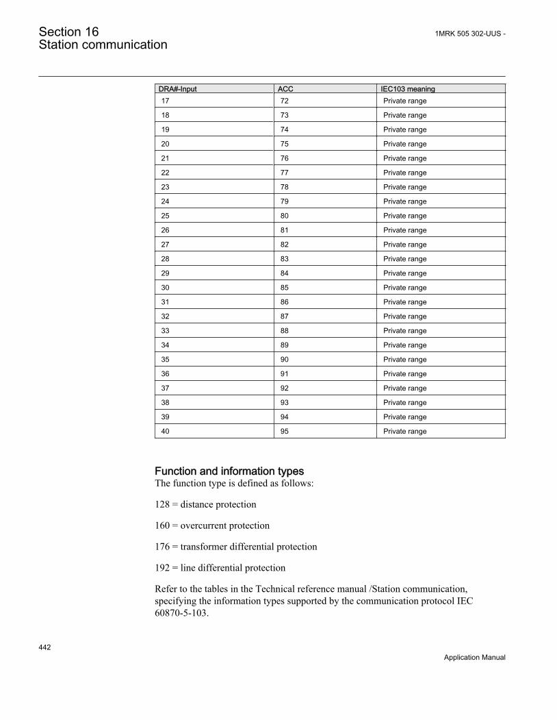
DRA#-Input ACC IEC103 meaning17 72 Private range
18 73 Private range
19 74 Private range
20 75 Private range
21 76 Private range
22 77 Private range
23 78 Private range
24 79 Private range
25 80 Private range
26 81 Private range
27 82 Private range
28 83 Private range
29 84 Private range
30 85 Private range
31 86 Private range
32 87 Private range
33 88 Private range
34 89 Private range
35 90 Private range
36 91 Private range
37 92 Private range
38 93 Private range
39 94 Private range
40 95 Private range
Function and information typesThe function type is defined as follows:
128 = distance protection
160 = overcurrent protection
176 = transformer differential protection
192 = line differential protection
Refer to the tables in the Technical reference manual /Station communication,specifying the information types supported by the communication protocol IEC60870-5-103.
Section 16 1MRK 505 302-UUS -Station communication
442Application Manual

To support the information, corresponding functions must be included in the protectionIED.
There is no representation for the following parts:
• Generating events for test mode• Cause of transmission: Info no 11, Local operation
EIA RS-485 is not supported. Glass or plastic fibre should be used. BFOC/2.5 is therecommended interface to use (BFOC/2.5 is the same as ST connectors). STconnectors are used with the optical power as specified in standard.
For more information, refer to IEC standard IEC 60870-5-103.
16.6 MULTICMDRCV and MULTICMDSND
16.6.1 IdentificationFunction description IEC 61850
identificationIEC 60617identification
ANSI/IEEE C37.2device number
Multiple command and receive MULTICMDRCV - -
Multiple command and send MULTICMDSND - -
16.6.2 ApplicationThe IED provides two function blocks enabling several IEDs to send and receivesignals via the interbay bus. The sending function block, MULTICMDSND, takes 16binary inputs. LON enables these to be transmitted to the equivalent receiving functionblock, MULTICMDRCV, which has 16 binary outputs.
16.6.3 Setting guidelines
16.6.3.1 Settings
The parameters for the multiple command function are set via PCM600.
The Mode setting sets the outputs to either a Steady or Pulsed mode.
1MRK 505 302-UUS - Section 16Station communication
443Application Manual

444

Section 17 Remote communication
17.1 Binary signal transfer
17.1.1 IdentificationFunction description IEC 61850
identificationIEC 60617identification
ANSI/IEEE C37.2device number
Binary signal transfer BinSignReceive - -
Binary signal transfer BinSignTransm - -
17.1.2 ApplicationThe IEDs can be equipped with communication devices for line differentialcommunication and/or communication of binary signals between IEDs. The samecommunication hardware is used for both purposes.
Communication between two IEDs geographically on different locations is afundamental part of the line differential function.
Sending of binary signals between two IEDs, one in each end of a power line is used inteleprotection schemes and for direct transfer trips. In addition to this, there areapplication possibilities, for example, blocking/enabling functionality in the remotesubstation, changing setting group in the remote IED depending on the switchingsituation in the local substation and so on.
When equipped with a LDCM, a 64 kbit/s communication channel can be connected tothe IED, which will then have the capacity of 192 binary signals to be communicatedwith a remote IED.
17.1.2.1 Communication hardware solutions
The LDCM (Line Data Communication Module) has an optical connection such thattwo IEDs can be connected over a direct fibre (multimode), as shown in figure 187.The protocol used is IEEE/ANSI C37.94. The distance with this solution is typical 110km/68 miles.
1MRK 505 302-UUS - Section 17Remote communication
445Application Manual
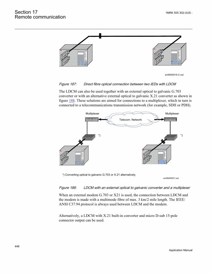
LDCM
LDCM
LDCM
LDCMLDCM
LDCMLDCMLDCM
LDCMLDCM
LDCM
LDCMLD
CMLD
CM
LDCMLDCM
en06000519-2.vsdIEC06000519 V2 EN
Figure 187: Direct fibre optical connection between two IEDs with LDCM
The LDCM can also be used together with an external optical to galvanic G.703converter or with an alternative external optical to galvanic X.21 converter as shown infigure 188. These solutions are aimed for connections to a multiplexer, which in turn isconnected to a telecommunications transmission network (for example, SDH or PDH).
LDCM
LDCM
LDCM
LDCM
Telecom. Network
*) *)
Multiplexer Multiplexer
LDCM
LDCMLDCMLDCM
LDCMLDCM
LDCM
LDCMLD
CMLD
CM
LDCMLDCM
en05000527.vsd*) Converting optical to galvanic G.703 or X.21 alternatively
IEC05000527 V1 EN
Figure 188: LDCM with an external optical to galvanic converter and a multiplexer
When an external modem G.703 or X21 is used, the connection between LDCM andthe modem is made with a multimode fibre of max. 3 km/2 mile length. The IEEE/ANSI C37.94 protocol is always used between LDCM and the modem.
Alternatively, a LDCM with X.21 built-in converter and micro D-sub 15-poleconnector output can be used.
Section 17 1MRK 505 302-UUS -Remote communication
446Application Manual

17.1.2.2 Application possibility with one-phase REB670
For busbar protection applications in substations where dynamic zone selection isrequired, it is typically necessary to wire the normally open and normally closedauxiliary contacts from every monitored disconnector and/or circuit breaker to theoptocoupler inputs of the busbar protection. When one phase version of REB670 isused, then six optocoupler inputs (that is, two in each phase/IED) are required for everyprimary switchgear object. For big stations (for example, with 24 bays) this willrequire quite a lot of binary inputs into every IED. To limit the number of requiredoptocoupler inputs into every IED it is possible to use LDCM communication modulesto effectively share the binary Ios between three units, as shown in figure 189189.
<= 192 Binary Signals =>
LDC
M#1
LDC
M#2
LDC
M#1
LDC
M#2
LDC
M#1
LDC
M#2
REB 670, B31Phase L1
<= 192 Binary Signals =>
<= 192 Binary Signals =>
Wire status of disconnectors
from Bays 01-08
Wire status of disconnectors
from Bays 09-16
Wire status of disconnectors
from Bays 17-24
REB 670, B31Phase L2
REB 670, B31Phase L3
en06000198.vsdIEC06000198 V2 EN
Figure 189: Example how to share binary IO between one-phase REB670 IEDs byusing LDCM modules
As shown in figure 189, it is possible to wire only the status for bays 01-08 to A phase-IED. After that the information about auxiliary contact status for switchgear objectsfrom these eight bays can be sent via LDCM modules to other two phases. In thesimilar way information from other bays can be only wired to B, respectively C phaseIED and then shared to the other two phases via LDCM communication.
1MRK 505 302-UUS - Section 17Remote communication
447Application Manual

Typical LDCM communication delay between two IEDs is in order of 30-40 ms. Notethat for disconnector status this delay will not pose any practical problems. However,time delay caused by LDCM communication can be crucial for circuit breakers status.In such cases it is strongly recommended that at least the circuit breaker closingcommand from every circuit breaker is directly wired to all three phases/IEDs tominimize any risk for unwanted operation of the busbar differential protection zonesdue to late inclusion of respective bay current into the differential measuring circuit.
17.1.3 Setting guidelinesChannelMode: This parameter can be set Enabled or Disabled. Besides this, it can beset OutOfService which signifies that the local LDCM is out of service. Thus, with thissetting, the communication channel is active and a message is sent to the remote IEDthat the local IED is out of service, but there is no COMFAIL signal and the analogand binary values are sent as zero.
TerminalNo: This setting shall be used to assign an unique address to each LDCM, inall current differential IEDs. Up to 256 LDCMs can be assigned a unique number.Consider a local IED with two LDCMs:
• LDCM for slot 302: Set TerminalNo to 1 and RemoteTermNo to 2• LDCM for slot 303: Set TerminalNo to 3 and RemoteTermNo to 4
In multiterminal current differential applications, with 4 LDCMs in each IED, up to 20unique addresses must be set.
The unique address is necessary to give high security against incorrectaddressing in the communication system. Using the same number forsetting TerminalNo in some of the LDCMs, a loop-back test in thecommunication system can give incorrect trip.
RemoteTermNo: This setting assigns a number to each related LDCM in the remoteIED. For each LDCM, the parameter RemoteTermNo shall be set to a different valuethan parameter TerminalNo, but equal to the TerminalNo of the remote end LDCM. Inthe remote IED the TerminalNo and RemoteTermNo settings are reversed as follows:
• LDCM for slot 302: Set TerminalNo to 2 and RemoteTermNo to 1• LDCM for slot 303: Set TerminalNo to 4 and RemoteTermNo to 3
The redundant channel is always configured in the lower position, forexample
Section 17 1MRK 505 302-UUS -Remote communication
448Application Manual

• Slot 302: Main channel• Slot 303: Redundant channel
The same is applicable for slot 312-313 and slot 322-323.
DiffSync: Here the method of time synchronization, Echo or GPS, for the linedifferential function is selected.
GPSSyncErr: If GPS synchronization is lost, the synchronization of the line differentialfunction will continue during 16 s. based on the stability in the local IED clocks.Thereafter the setting Block will block the line differential function or the setting Echowill make it continue by using the Echo synchronization method. It shall be noticedthat using Echo in this situation is only safe as long as there is no risk of varyingtransmission asymmetry.
CommSync: This setting decides the Master or Slave relation in the communicationsystem and shall not be mistaken for the synchronization of line differential currentsamples. When direct fibre is used, one LDCM is set as Master and the other one asSlave. When a modem and multiplexer is used, the IED is always set as Slave, as thetelecommunication system will provide the clock master.
OptoPower: The setting LowPower is used for fibres 0 – 1 km (0.6 mile) andHighPower for fibres >1 km (>0.6 mile).
TransmCurr: This setting decides which of 2 possible local currents that shall betransmitted, or if and how the sum of 2 local currents shall be transmitted, or finally ifthe channel shall be used as a redundant channel.
In a breaker-and-a-half arrangement, there will be 2 local currents, and the groundingon the CTs can be different for these. CT-SUM will transmit the sum of the 2 CTgroups. CT-DIFF1 will transmit CT group 1 minus CT group 2 and CT-DIFF2 willtransmit CT group 2 minus CT group 1.
CT-GRP1 or CT-GRP2 will transmit the respective CT group, and the settingRedundantChannel makes the channel be used as a backup channel.
ComFailAlrmDel: Time delay of communication failure alarm. In communicationsystems, route switching can sometimes cause interruptions with a duration up to 50ms. Thus, a too short time delay setting might cause nuisance alarms in these situations.
ComFailResDel: Time delay of communication failure alarm reset.
RedChSwTime: Time delay before switchover to a redundant channel in case ofprimary channel failure.
1MRK 505 302-UUS - Section 17Remote communication
449Application Manual

RedChRturnTime: Time delay before switchback to a the primary channel after channelfailure.
AsymDelay: The asymmetry is defined as transmission delay minus receive delay. If afixed asymmetry is known, the Echo synchronization method can be used if theparameter AsymDelay is properly set. From the definition follows that the asymmetrywill always be positive in one end, and negative in the other end.
AnalogLatency: Local analog latency; A parameter which specifies the time delay(number of samples) between actual sampling and the time the sample reaches thelocal communication module, LDCM. The parameter shall be set to 2 whentransmitting analog data from the local transformer module, TRM. .
RemAinLatency: Remote analog latency; This parameter corresponds to theLocAinLatency set in the remote IED.
MaxTransmDelay: Data for maximum 40 ms transmission delay can be buffered up.Delay times in the range of some ms are common. It shall be noticed that if data arrivein the wrong order, the oldest data will just be disregarded.
CompRange: The set value is the current peak value over which truncation will bemade. To set this value, knowledge of the fault current levels should be known. Thesetting is not overly critical as it considers very high current values for which correctoperation normally still can be achieved.
MaxtDiffLevel: Allowed maximum time difference between the internal clocks inrespective line end.
Section 17 1MRK 505 302-UUS -Remote communication
450Application Manual
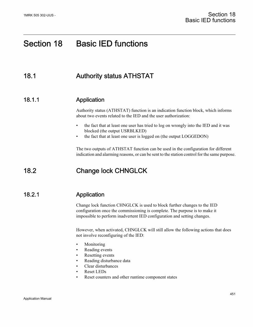
Section 18 Basic IED functions
18.1 Authority status ATHSTAT
18.1.1 ApplicationAuthority status (ATHSTAT) function is an indication function block, which informsabout two events related to the IED and the user authorization:
• the fact that at least one user has tried to log on wrongly into the IED and it wasblocked (the output USRBLKED)
• the fact that at least one user is logged on (the output LOGGEDON)
The two outputs of ATHSTAT function can be used in the configuration for differentindication and alarming reasons, or can be sent to the station control for the same purpose.
18.2 Change lock CHNGLCK
18.2.1 ApplicationChange lock function CHNGLCK is used to block further changes to the IEDconfiguration once the commissioning is complete. The purpose is to make itimpossible to perform inadvertent IED configuration and setting changes.
However, when activated, CHNGLCK will still allow the following actions that doesnot involve reconfiguring of the IED:
• Monitoring• Reading events• Resetting events• Reading disturbance data• Clear disturbances• Reset LEDs• Reset counters and other runtime component states
1MRK 505 302-UUS - Section 18Basic IED functions
451Application Manual

• Control operations• Set system time• Enter and exit from test mode• Change of active setting group
The binary input controlling the function is defined in ACT or SMT. The CHNGLCKfunction is configured using ACT.
LOCK Binary input signal that will activate/deactivate the function, defined in ACT or SMT.
When CHNGLCK has a logical one on its input, then all attempts to modify the IEDconfiguration and setting will be denied and the message "Error: Changes blocked"will be displayed on the local HMI; in PCM600 the message will be "Operation deniedby active ChangeLock". The CHNGLCK function should be configured so that it iscontrolled by a signal from a binary input card. This guarantees that by setting thatsignal to a logical zero, CHNGLCK is deactivated. If any logic is included in the signalpath to the CHNGLCK input, that logic must be designed so that it cannot permanentlyissue a logical one to the CHNGLCK input. If such a situation would occur in spite ofthese precautions, then please contact the local ABB representative for remedial action.
18.3 Denial of service DOS
18.3.1 ApplicationThe denial of service functions (DOSFRNT, DOSLANAB and DOSLANCD) aredesigned to limit the CPU load that can be produced by Ethernet network traffic on theIED. The communication facilities must not be allowed to compromise the primaryfunctionality of the device. All inbound network traffic will be quota controlled so thattoo heavy network loads can be controlled. Heavy network load might for instance bethe result of malfunctioning equipment connected to the network.
DOSFRNT, DOSLANAB and DOSLANCD measure the IED load fromcommunication and, if necessary, limit it for not jeopardizing the IEDs control andprotection functionality due to high CPU load. The function has the following outputs:
• LINKUP indicates the Ethernet link status• WARNING indicates that communication (frame rate) is higher than normal• ALARM indicates that the IED limits communication
Section 18 1MRK 505 302-UUS -Basic IED functions
452Application Manual

18.3.2 Setting guidelinesThe function does not have any parameters available in the local HMI or PCM600.
18.4 IED identifiers
18.4.1 ApplicationIED identifiers (TERMINALID) function allows the user to identify the individual IEDin the system, not only in the substation, but in a whole region or a country.
Use only characters A-Z, a-z and 0-9 in station, object and unit names.
18.5 Product information
18.5.1 ApplicationThe Product identifiers function contains constant data (i.e. not possible to change) thatuniquely identifies the IED:
• ProductVer• ProductDef• SerialNo• OrderingNo• ProductionDate• IEDProdType
The settings are visible on the local HMI , under Main menu/Diagnostics/IED status/Product identifiersand underMain menu/Diagnostics/IED Status/IED identifiers
This information is very helpful when interacting with ABB product support (e.g.during repair and maintenance).
18.5.2 Factory defined settingsThe factory defined settings are very useful for identifying a specific version and veryhelpful in the case of maintenance, repair, interchanging IEDs between different
1MRK 505 302-UUS - Section 18Basic IED functions
453Application Manual

Substation Automation Systems and upgrading. The factory made settings can not bechanged by the customer. They can only be viewed. The settings are found in the localHMI under Main menu/Diagnostics/IED status/Product identifiers
The following identifiers are available:
• IEDProdType• Describes the type of the IED (like REL, REC or RET). Example: REL670
• ProductDef• Describes the release number, from the production. Example: 1.2.2.0
• ProductVer• Describes the product version. Example: 1.2.3
1 is the Major version of the manufactured product this means, new platform of the product
2 is the Minor version of the manufactured product this means, new functions or newhardware added to the product
3 is the Major revision of the manufactured product this means, functions or hardware iseither changed or enhanced in the product
• IEDMainFunType• Main function type code according to IEC 60870-5-103. Example: 128
(meaning line protection).• SerialNo• OrderingNo• ProductionDate
18.6 Measured value expander block RANGE_XP
18.6.1 IdentificationFunction description IEC 61850
identificationIEC 60617identification
ANSI/IEEE C37.2device number
Measured value expander block RANGE_XP - -
18.6.2 ApplicationThe current and voltage measurements functions (CVMMXN, CMMXU, VMMXUand VNMMXU), current and voltage sequence measurement functions (CMSQI andVMSQI) and IEC 61850 generic communication I/O functions (MVGAPC) are
Section 18 1MRK 505 302-UUS -Basic IED functions
454Application Manual

provided with measurement supervision functionality. All measured values can besupervised with four settable limits, that is low-low limit, low limit, high limit and high-high limit. The measure value expander block ( RANGE_XP) has been introduced tobe able to translate the integer output signal from the measuring functions to 5 binarysignals, that is below low-low limit, below low limit, normal, above high-high limit orabove high limit. The output signals can be used as conditions in the configurable logic.
18.6.3 Setting guidelinesThere are no settable parameters for the measured value expander block function.
18.7 Parameter setting groups
18.7.1 ApplicationSix sets of settings are available to optimize IED operation for different power systemconditions. By creating and switching between fine tuned setting sets, either from thelocal HMI or configurable binary inputs, results in a highly adaptable IED that cancope with a variety of power system scenarios.
Different conditions in networks with different voltage levels require highly adaptableprotection and control units to best provide for dependability, security and selectivityrequirements. Protection units operate with a higher degree of availability, especially,if the setting values of their parameters are continuously optimized according to theconditions in the power system.
Operational departments can plan for different operating conditions in the primaryequipment. The protection engineer can prepare the necessary optimized and pre-testedsettings in advance for different protection functions. Six different groups of settingparameters are available in the IED. Any of them can be activated through the differentprogrammable binary inputs by means of external or internal control signals.
A function block, SETGRPS, defines how many setting groups are used. Setting isdone with parameter MAXSETGR and shall be set to the required value for each IED.Only the number of setting groups set will be available in the Parameter Setting toolfor activation with the ActiveGroup function block.
18.7.2 Setting guidelinesThe setting ActiveSetGrp, is used to select which parameter group to be active. Theactive group can also be selected with configured input to the function blockSETGRPS.
1MRK 505 302-UUS - Section 18Basic IED functions
455Application Manual

The length of the pulse, sent out by the output signal GRP_CHGD when an activegroup has changed, is set with the parameter t.
The parameter MAXSETGR defines the maximum number of setting groups in use toswitch between. Only the selected number of setting groups will be available in theParameter Setting tool (PST) for activation with the ActiveGroup function block.
18.8 Rated system frequency PRIMVAL
18.8.1 IdentificationFunction description IEC 61850
identificationIEC 60617identification
ANSI/IEEE C37.2device number
Primary system values PRIMVAL - -
18.8.2 ApplicationThe rated system frequency is set under Main menu/General settings/ Power system/Primary Values in the local HMI and PCM600 parameter setting tree.
18.8.3 Setting guidelinesSet the system rated frequency. Refer to section "Signal matrix for analog inputsSMAI" for description on frequency tracking.
18.9 Summation block 3 phase 3PHSUM
18.9.1 ApplicationThe analog summation block 3PHSUM function block is used in order to get the sumof two sets of 3 phase analog signals (of the same type) for those IED functions thatmight need it.
Section 18 1MRK 505 302-UUS -Basic IED functions
456Application Manual
18.9.2 Setting guidelinesThe summation block receives the three-phase signals from SMAI blocks. Thesummation block has several settings.
SummationType: Summation type (Group 1 + Group 2, Group 1 - Group 2, Group 2 -Group 1 or –(Group 1 + Group 2)).
DFTReference: The reference DFT block (InternalDFT Ref,DFTRefGrp1 or ExternalDFT ref) .
FreqMeasMinVal: The minimum value of the voltage for which the frequency iscalculated, expressed as percent of VBasebase voltage setting (for each instance x).
GlobalBaseSel: Selects the global base value group used by the function to define(IBase), (VBase) and (SBase).
18.10 Global base values GBASVAL
18.10.1 IdentificationFunction description IEC 61850
identificationIEC 60617identification
ANSI/IEEE C37.2device number
Global base values GBASVAL - -
18.10.2 ApplicationGlobal base values function (GBASVAL) is used to provide global values, commonfor all applicable functions within the IED. One set of global values consists of valuesfor current, voltage and apparent power and it is possible to have six different sets.
This is an advantage since all applicable functions in the IED use a single source ofbase values. This facilitates consistency throughout the IED and also facilitates a singlepoint for updating values when necessary.
Each applicable function in the IED has a parameter, GlobalBaseSel, defining one outof the six sets of GBASVAL functions.
1MRK 505 302-UUS - Section 18Basic IED functions
457Application Manual
18.10.3 Setting guidelinesVBase: Phase-to-phase voltage value to be used as a base value for applicable functionsthroughout the IED.
IBase: Phase current value to be used as a base value for applicable functionsthroughout the IED.
SBase: Standard apparent power value to be used as a base value for applicablefunctions throughout the IED, typically SBase=√3·VBase·IBase.
18.11 Signal matrix for binary inputs SMBI
18.11.1 ApplicationThe Signal matrix for binary inputs function SMBI is used within the ApplicationConfiguration tool in direct relation with the Signal Matrix tool. SMBI represents theway binary inputs are brought in for one IED configuration.
18.11.2 Setting guidelinesThere are no setting parameters for the Signal matrix for binary inputs SMBI availableto the user in Parameter Setting tool. However, the user shall give a name to SMBIinstance and the SMBI inputs, directly in the Application Configuration tool. Thesenames will define SMBI function in the Signal Matrix tool. The user defined name forthe input or output signal will also appear on the respective output or input signal.
18.12 Signal matrix for binary outputs SMBO
18.12.1 ApplicationThe Signal matrix for binary outputs function SMBO is used within the ApplicationConfiguration tool in direct relation with the Signal Matrix tool. SMBO represents theway binary outputs are sent from one IED configuration.
Section 18 1MRK 505 302-UUS -Basic IED functions
458Application Manual
18.12.2 Setting guidelinesThere are no setting parameters for the Signal matrix for binary outputs SMBOavailable to the user in Parameter Setting tool. However, the user must give a name toSMBO instance and SMBO outputs, directly in the Application Configuration tool.These names will define SMBO function in the Signal Matrix tool.
18.13 Signal matrix for analog inputs SMAI
18.13.1 ApplicationSignal matrix for analog inputs (SMAI), also known as the preprocessor functionblock, analyses the connected four analog signals (three phases and neutral) andcalculates all relevant information from them like the phasor magnitude, phase angle,frequency, true RMS value, harmonics, sequence components and so on. Thisinformation is then used by the respective functions connected to this SMAI block inACT (for example protection, measurement or monitoring functions).
18.13.2 Frequency valuesThe frequency functions includes a functionality based on level of positive sequencevoltage, IntBlockLevel, to validate if the frequency measurement is valid or not. Ifpositive sequence voltage is lower than IntBlockLevel the function is blocked.IntBlockLevel, is set in % of VBase/√3
If SMAI setting ConnectionType is Ph-Ph at least two of the inputs GRPx_A, GRPx_Band GRPx_C must be connected in order to calculate positive sequence voltage. Notethat phase to phase inputs shall always be connected as follows: L1-L2 to GRPxL1, L2-L3 to GRPxL2, L3-L1 to GRPxL3. If SMAI setting ConnectionType is Ph-N, all threeinputs GRPx_A, GRPx_B and GRPx_C must be connected in order to calculatepositive sequence voltage.
If only one phase-phase voltage is available and SMAI setting ConnectionType is Ph-Ph the user is advised to connect two (not three) of the inputs GRPx_A, GRPx_B andGRPx_C to the same voltage input as shown in figure 190 to make SMAI calculating apositive sequence voltage.
1MRK 505 302-UUS - Section 18Basic IED functions
459Application Manual

IEC10000060-1-en.vsd
IEC10000060 V1 EN
Figure 190: Connection example
The above described scenario does not work if SMAI settingConnectionType is Ph-N. If only one phase-ground voltage is available,the same type of connection can be used but the SMAI ConnectionTypesetting must still be Ph-Ph and this has to be accounted for whensetting IntBlockLevel. If SMAI setting ConnectionType is Ph-N and thesame voltage is connected to all three SMAI inputs, the positivesequence voltage will be zero and the frequency functions will notwork properly.
The outputs from the above configured SMAI block shall only be usedfor Overfrequency protection (SAPTOF, 81), Underfrequencyprotection (SAPTUF, 81) and Rate-of-change frequency protection(SAPFRC, 81) due to that all other information except frequency andpositive sequence voltage might be wrongly calculated.
18.13.3 Setting guidelinesThe parameters for the signal matrix for analog inputs (SMAI) functions are set via thelocal HMI or PCM600.
Every SMAI function block can receive four analog signals (three phases and oneneutral value), either voltage or current. SMAI outputs give information about everyaspect of the 3ph analog signals acquired (phase angle, RMS value, frequency andfrequency derivates, and so on – 244 values in total). Besides the block “group name”,the analog inputs type (voltage or current) and the analog input names that can be setdirectly in ACT.
Application functions should be connected to a SMAI block with same task cycle asthe application function, except for e.g. measurement functions that run in slow cycletasks.
Section 18 1MRK 505 302-UUS -Basic IED functions
460Application Manual

DFTRefExtOut: Parameter valid only for function block SMAI1 .
Reference block for external output (SPFCOUT function output).
DFTReference: Reference DFT for the SMAI block use.
These DFT reference block settings decide DFT reference for DFT calculations. Thesetting InternalDFTRef will use fixed DFT reference based on set system frequency.DFTRefGrp(n) will use DFT reference from the selected group block, when own groupis selected, an adaptive DFT reference will be used based on calculated signalfrequency from own group. The setting ExternalDFTRef will use reference based onwhat is connected to input DFTSPFC.
The setting ConnectionType: Connection type for that specific instance (n) of theSMAI (if it is Ph-N or Ph-Ph). Depending on connection type setting the not connectedPh-N or Ph-Ph outputs will be calculated as long as they are possible to calculate. E.g.at Ph-Ph connection A, B and C will be calculated for use in symmetrical situations. IfN component should be used respectively the phase component during faults IN/VNmust be connected to input 4.
Negation: If the user wants to negate the 3ph signal, it is possible to choose to negateonly the phase signals Negate3Ph, only the neutral signal NegateN or both Negate3Ph+N. negation means rotation with 180° of the vectors.
GlobalBaseSel: Selects the global base value group used by the function to define(IBase), (VBase) and (SBase).
MinValFreqMeas: The minimum value of the voltage for which the frequency iscalculated, expressed as percent of VBase (for each instance n).
Settings DFTRefExtOut and DFTReference shall be set to default valueInternalDFTRef if no VT inputs are available.
Even if the user sets the AnalogInputType of a SMAI block to“Current”, the MinValFreqMeas is still visible. However, using thecurrent channel values as base for frequency measurement is notrecommendable for a number of reasons, not last among them beingthe low level of currents that one can have in normal operating conditions.
Examples of adaptive frequency tracking
Preprocessing block shall only be used to feed functions within thesame execution cycles (e.g. use preprocessing block with cycle 1 tofeed transformer differential protection). The only exceptions are
1MRK 505 302-UUS - Section 18Basic IED functions
461Application Manual

measurement functions (CVMMXN, CMMXU,VMMXU, etc.) whichshall be fed by preprocessing blocks with cycle 8.
When two or more preprocessing blocks are used to feed one protectionfunction (e.g. over-power function GOPPDOP), it is of outmostimportance that parameter setting DFTReference has the same set valuefor all of the preprocessing blocks involved
Section 18 1MRK 505 302-UUS -Basic IED functions
462Application Manual
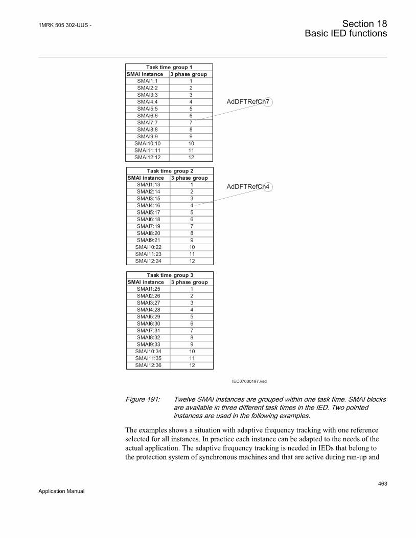
IEC07000197.vsd
SMAI instance 3 phase groupSMAI1:1 1SMAI2:2 2SMAI3:3 3SMAI4:4 4SMAI5:5 5SMAI6:6 6SMAI7:7 7SMAI8:8 8SMAI9:9 9
SMAI10:10 10SMAI11:11 11SMAI12:12 12
Task time group 1
SMAI instance 3 phase groupSMAI1:13 1SMAI2:14 2SMAI3:15 3SMAI4:16 4SMAI5:17 5SMAI6:18 6SMAI7:19 7SMAI8:20 8SMAI9:21 9
SMAI10:22 10SMAI11:23 11SMAI12:24 12
Task time group 2
SMAI instance 3 phase groupSMAI1:25 1SMAI2:26 2SMAI3:27 3SMAI4:28 4SMAI5:29 5SMAI6:30 6SMAI7:31 7SMAI8:32 8SMAI9:33 9
SMAI10:34 10SMAI11:35 11SMAI12:36 12
Task time group 3
AdDFTRefCh7
AdDFTRefCh4
IEC07000197 V2 EN
Figure 191: Twelve SMAI instances are grouped within one task time. SMAI blocksare available in three different task times in the IED. Two pointedinstances are used in the following examples.
The examples shows a situation with adaptive frequency tracking with one referenceselected for all instances. In practice each instance can be adapted to the needs of theactual application. The adaptive frequency tracking is needed in IEDs that belong tothe protection system of synchronous machines and that are active during run-up and
1MRK 505 302-UUS - Section 18Basic IED functions
463Application Manual

shout-down of the machine. In other application the usual setting of the parameterDFTReference of SMAI is InternalDFTRef.
Example 1
ANSI07000198.vsd
SMAI1:1BLOCKDFTSPFC^GRP1_A^GRP1_B^GRP1_C^GRP1_NTYPE
SPFCOUTAI3P
AI1AI2AI3AI4AIN
SMAI1:13BLOCKDFTSPFC^GRP1_A^GRP1_B^GRP1_C^GRP1_NTYPE
SPFCOUTAI3P
AI1AI2AI3AI4AIN
SMAI1:25BLOCKDFTSPFC^GRP1_A^GRP1_B^GRP1_C^GRP1_NTYPE
SPFCOUTAI3P
AI1AI2AI3AI4AIN
ANSI07000198 V1 EN
Figure 192: Configuration for using an instance in task time group 1 as DFT reference
Assume instance SMAI7:7 in task time group 1 has been selected in the configurationto control the frequency tracking . Observe that the selected reference instance (i.e.frequency tracking master) must be a voltage type. Observe that positive sequencevoltage is used for the frequency tracking feature.
For task time group 1 this gives the following settings (see Figure 191 for numbering):
SMAI1:1: DFTRefExtOut = DFTRefGrp7 to route SMAI7:7 reference to theSPFCOUT output, DFTReference = DFTRefGrp7 for SMAI1:1 to use SMAI7:7 asreference (see Figure 192) SMAI2:2 – SMAI12:12: DFTReference = DFTRefGrp7 forSMAI2:2 – SMAI12:12 to use SMAI7:7 as reference.
For task time group 2 this gives the following settings:
SMAI1:13 – SMAI12:24: DFTReference = ExternalDFTRef to use DFTSPFC input ofSMAI1:13 as reference (SMAI7:7)
For task time group 3 this gives the following settings:
SMAI1:25 – SMAI12:36: DFTReference = ExternalDFTRef to use DFTSPFC input asreference (SMAI7:7)
Section 18 1MRK 505 302-UUS -Basic IED functions
464Application Manual
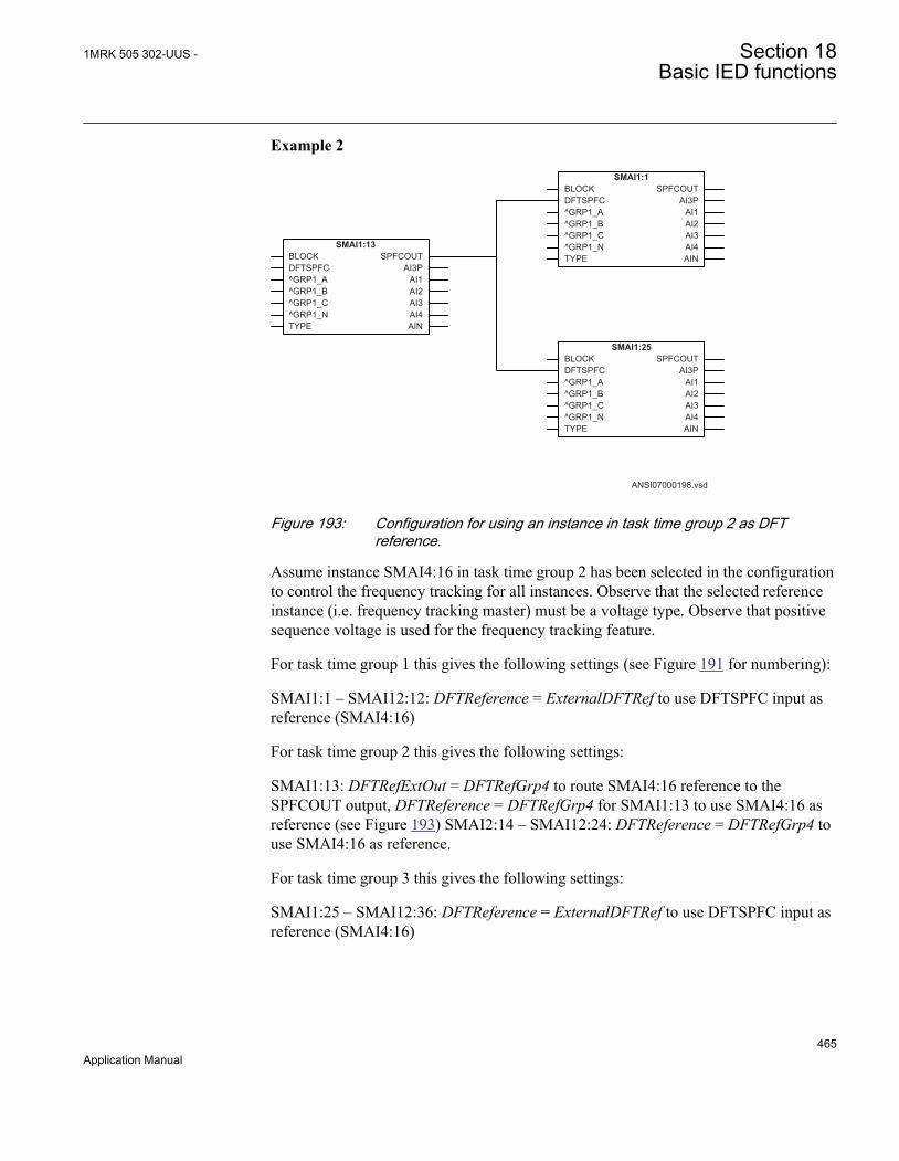
Example 2
ANSI07000198.vsd
SMAI1:13BLOCKDFTSPFC^GRP1_A^GRP1_B^GRP1_C^GRP1_NTYPE
SPFCOUTAI3P
AI1AI2AI3AI4AIN
SMAI1:1BLOCKDFTSPFC^GRP1_A^GRP1_B^GRP1_C^GRP1_NTYPE
SPFCOUTAI3P
AI1AI2AI3AI4AIN
SMAI1:25BLOCKDFTSPFC^GRP1_A^GRP1_B^GRP1_C^GRP1_NTYPE
SPFCOUTAI3P
AI1AI2AI3AI4AIN
ANSI07000199 V1 EN
Figure 193: Configuration for using an instance in task time group 2 as DFTreference.
Assume instance SMAI4:16 in task time group 2 has been selected in the configurationto control the frequency tracking for all instances. Observe that the selected referenceinstance (i.e. frequency tracking master) must be a voltage type. Observe that positivesequence voltage is used for the frequency tracking feature.
For task time group 1 this gives the following settings (see Figure 191 for numbering):
SMAI1:1 – SMAI12:12: DFTReference = ExternalDFTRef to use DFTSPFC input asreference (SMAI4:16)
For task time group 2 this gives the following settings:
SMAI1:13: DFTRefExtOut = DFTRefGrp4 to route SMAI4:16 reference to theSPFCOUT output, DFTReference = DFTRefGrp4 for SMAI1:13 to use SMAI4:16 asreference (see Figure 193) SMAI2:14 – SMAI12:24: DFTReference = DFTRefGrp4 touse SMAI4:16 as reference.
For task time group 3 this gives the following settings:
SMAI1:25 – SMAI12:36: DFTReference = ExternalDFTRef to use DFTSPFC input asreference (SMAI4:16)
1MRK 505 302-UUS - Section 18Basic IED functions
465Application Manual

18.14 Test mode functionality TEST
18.14.1 ApplicationThe protection and control IEDs may have a complex configuration with manyincluded functions. To make the testing procedure easier, the IEDs include the featurethat allows individual blocking of a single-, several-, or all functions.
This means that it is possible to see when a function is activated or trips. It also enablesthe user to follow the operation of several related functions to check correctfunctionality and to check parts of the configuration, and so on.
18.14.1.1 IEC 61850 protocol test mode
The IEC 61850 Test Mode has improved testing capabilities for IEC 61850 systems.Operator commands sent to the IEC 61850 Mod determine the behavior of thefunctions. The command can be given from the LHMI under the Main menu/Test/Function test modes menu or remotely from an IEC 61850 client. The possible valuesof IEC 61850 Mod are described in Communication protocol manual, IEC 61850Edition 1 and Edition 2.
To be able to set the IEC61850 Mod the parameter remotely, the PSTsetting RemoteModControl may not be set to Off. The possible valuesare Off, Maintenance or All levels. The Off value denies all access todata object Mod from remote, Maintenance requires that the categoryof the originator (orCat) is Maintenance and All levels allow any orCat.
The mod of the Root LD.LNN0 can be configured under Main menu/Test/Functiontest modes/Communication/Station communication/IEC61850 LD0 LLN0/LD0LLN0:1
When the Mod is changed at this level, all components under the logical device updatetheir own behavior according to IEC61850-7-4. The supported values of IEC61850Mod are described in Communication protocol manual, IEC 61850 Edition 2. TheIEC61850 test mode is indicated with the Start LED on the LHMI.
The mod of an specific component can be configured under Main menu/Test/Function test modes/Communication/Station Communication
It is possible that the behavior is also influenced by other sources as well, independentof the mode, such as the insertion of the test handle, loss of SV, and IED configuration
Section 18 1MRK 505 302-UUS -Basic IED functions
466Application Manual
or LHMI. If a function of an IED is set to Off, the related Beh is set to Off as well. Therelated mod keeps its current state.
When the setting Operation is set to Off, the behavior is set to Off and it is not possibleto override it. When a behavior of a function is Offthe function will not execute.
When IEC61850 Mod of a function is set to Off or Blocked, the StartLED on the LHMI will be set to flashing to indicate the abnormaloperation of the IED.
The IEC61850-7-4 gives a detailed overview over all aspects of the test mode andother states of mode and behavior.
• When the Beh of a component is set to Test, the component is not blocked and allcontrol commands with a test bit are accepted.
• When the Beh of a component is set to Test/blocked, all control commands with atest bit are accepted. Outputs to the process via a non-IEC 61850 link data areblocked by the LN. Only process-related outputs on LNs related to primaryequipment are blocked. If there is an XCBR, the outputs EXC_Open andEXC_Close are blocked.
• When the Beh of a component is set to Blocked, all control commands with a testbit are accepted. Outputs to the process via a non-IEC 61850 link data are blockedby the LN. In addition, the components can be blocked when their Beh is blocked.This can be done if the component has a block input. The block status of acomponent is shown as the Blk output under the Test/Function status menu. If theBlk output is not shown, the component cannot be blocked.
18.14.2 Setting guidelinesRemember always that there are two possible ways to place the IED in the TestMode=Enabled” state. If, the IED is set to normal operation (TestMode = Disabled), but thefunctions are still shown being in the test mode, the input signal INPUT on theTESTMODE function block might be activated in the configuration.
18.15 Self supervision with internal event list
18.15.1 ApplicationThe protection and control IEDs have many functions included . The included self-supervision with internal event list function block provides good supervision of theIED. The fault signals make it easier to analyze and locate a fault.
1MRK 505 302-UUS - Section 18Basic IED functions
467Application Manual

Both hardware and software supervision is included and it is also possible to indicatepossible faults through a hardware contact on the power supply module and/or throughthe software communication.
Internal events are generated by the built-in supervisory functions. The supervisoryfunctions supervise the status of the various modules in the IED and, in case of failure,a corresponding event is generated. Similarly, when the failure is corrected, acorresponding event is generated.
Apart from the built-in supervision of the various modules, events are also generatedwhen the status changes for the:
• built-in real time clock (in operation/out of order).• external time synchronization (in operation/out of order).
Events are also generated:
• whenever any setting in the IED is changed.
The internal events are time tagged with a resolution of 1 ms and stored in a list. Thelist can store up to 40 events. The list is based on the FIFO principle, that is, when it isfull, the oldest event is overwritten. The list contents cannot be modified, but the wholelist can be cleared using the Reset menu in the LHMI.
The list of internal events provides valuable information, which can be used duringcommissioning and fault tracing.
The information can only be retrieved with the aid of PCM600 Event Monitoring Tool.The PC can either be connected to the front port, or to the port at the back of the IED.
18.16 Time synchronization
18.16.1 ApplicationUse time synchronization to achieve a common time base for the IEDs in a protectionand control system. This makes it possible to compare events and disturbance databetween all IEDs in the system.
Time-tagging of internal events and disturbances are an excellent help when evaluatingfaults. Without time synchronization, only the events within the IED can be comparedto one another. With time synchronization, events and disturbances within the entirestation, and even between line ends, can be compared at evaluation.
In the IED, the internal time can be synchronized from a number of sources:
Section 18 1MRK 505 302-UUS -Basic IED functions
468Application Manual

• BIN (Binary Minute Pulse)• DNP• GPS• IEC103• SNTP• IRIG-B• SPA• LON• PPS
Out of these, LON and SPA contains two types of synchronization messages:
• Coarse time messages are sent every minute and contain complete date and time,that is year, month, day, hour, minute, second and millisecond.
• Fine time messages are sent every second and comprise only seconds andmilliseconds.
The setting tells the IED which of these that shall be used to synchronize the IED.
It is possible to set a backup time-source for GPS signal, for instance SNTP. In thiscase, when the GPS signal quality is bad, the IED will automatically choose SNTP asthe time-source. At a given point in time, only one time-source will be used.
18.16.2 Setting guidelines
System timeThe time is set with years, month, day, hour, minute, second and millisecond.
SynchronizationThe setting parameters for the real-time clock with external time synchronization(TIME) are set via local HMI or PCM600.
TimeSynchWhen the source of the time synchronization is selected on the local HMI, theparameter is called TimeSynch. The time synchronization source can also be set fromPCM600. The setting alternatives are:
FineSyncSource which can have the following values:
• Disabled• SPA• LON• BIN (Binary Minute Pulse)• GPS
1MRK 505 302-UUS - Section 18Basic IED functions
469Application Manual
• GPS+SPA• GPS+LON• GPS+BIN• SNTP• GPS+SNTP• GPS+IRIG-B• IRIG-B• PPS
CoarseSyncSrc which can have the following values:
• Disabled• SPA• LON• SNTP• DNP
The function input to be used for minute-pulse synchronization is called BININPUT.
The system time can be set manually, either via the local HMI or via any of thecommunication ports. The time synchronization fine tunes the clock (seconds andmilliseconds).
The parameter SyncMaster defines if the IED is a master, or not a master for timesynchronization in a system of IEDs connected in a communication network(IEC61850-8-1). The SyncMaster can have the following values:
• Disabled• SNTP -Server
Set the course time synchronizing source (CoarseSyncSrc) to Disabledwhen GPS time synchronization of line differential function is used. Setthe fine time synchronization source (FineSyncSource) to GPS. TheGPS will thus provide the complete time synchronization. GPS aloneshall synchronize the analogue values in such systems.
Section 18 1MRK 505 302-UUS -Basic IED functions
470Application Manual
Section 19 Requirements
19.1 Current transformer requirements
The performance of a protection function will depend on the quality of the measuredcurrent signal. Saturation of the current transformers (CTs) will cause distortion of thecurrent signals and can result in a failure to operate or cause unwanted operations ofsome functions. Consequently CT saturation can have an influence on both thedependability and the security of the protection. This protection IED has been designedto permit heavy CT saturation with maintained correct operation.
19.1.1 Current transformer classificationTo guarantee correct operation, the current transformers (CTs) must be able tocorrectly reproduce the current for a minimum time before the CT will begin tosaturate. To fulfill the requirement on a specified time to saturation the CTs must fulfillthe requirements of a minimum secondary e.m.f. that is specified below.
There are several different ways to specify CTs. Conventional magnetic core CTs areusually specified and manufactured according to some international or nationalstandards, which specify different protection classes as well. There are many differentstandards and a lot of classes but fundamentally there are three different types of CTs:
• High remanence type CT• Low remanence type CT• Non remanence type CT
The high remanence type has no limit for the remanent flux. This CT has a magneticcore without any airgaps and a remanent flux might remain almost infinite time. In thistype of transformers the remanence can be up to around 80% of the saturation flux.Typical examples of high remanence type CT are class P, PX, TPX according to IEC,class P, X according to BS (old British Standard) and non gapped class C, K accordingto ANSI/IEEE.
The low remanence type has a specified limit for the remanent flux. This CT is madewith a small air gap to reduce the remanence to a level that does not exceed 10% of thesaturation flux. The small air gap has only very limited influences on the otherproperties of the CT. Class PXR, TPY according to IEC are low remanence type CTs.
1MRK 505 302-UUS - Section 19Requirements
471Application Manual

The non remanence type CT has practically negligible level of remanent flux. Thistype of CT has relatively big air gaps in order to reduce the remanence to practicallyzero level. In the same time, these air gaps reduce the influence of the DC-componentfrom the primary fault current. The air gaps will also decrease the measuring accuracyin the non-saturated region of operation. Class TPZ according to IEC is a nonremanence type CT.
Different standards and classes specify the saturation e.m.f. in different ways but it ispossible to approximately compare values from different classes. The rated equivalentlimiting secondary e.m.f. Eal according to the IEC 61869–2 standard is used to specifythe CT requirements for the IED. The requirements are also specified according toother standards.
19.1.2 ConditionsThe requirements are a result of investigations performed in our network simulator.The current transformer models are representative for current transformers of highremanence and low remanence type. The results may not always be valid for nonremanence type CTs (TPZ).
The performances of the protection functions have been checked in the range fromsymmetrical to fully asymmetrical fault currents. Primary time constants of at least 120ms have been considered at the tests. The current requirements below are thusapplicable both for symmetrical and asymmetrical fault currents.
Depending on the protection function phase-to-ground, phase-to-phase and three-phasefaults have been tested for different relevant fault positions for example, close inforward and reverse faults, zone 1 reach faults, internal and external faults. Thedependability and security of the protection was verified by checking for example, timedelays, unwanted operations, directionality, overreach and stability.
The remanence in the current transformer core can cause unwanted operations or minoradditional time delays for some protection functions. As unwanted operations are notacceptable at all maximum remanence has been considered for fault cases critical forthe security, for example, faults in reverse direction and external faults. Because of thealmost negligible risk of additional time delays and the non-existent risk of failure tooperate the remanence have not been considered for the dependability cases. Therequirements below are therefore fully valid for all normal applications.
It is difficult to give general recommendations for additional margins for remanence toavoid the minor risk of an additional time delay. They depend on the performance andeconomy requirements. When current transformers of low remanence type (forexample, TPY, PR) are used, normally no additional margin is needed. For currenttransformers of high remanence type (for example, P, PX, TPX) the small probabilityof fully asymmetrical faults, together with high remanence in the same direction as the
Section 19 1MRK 505 302-UUS -Requirements
472Application Manual

flux generated by the fault, has to be kept in mind at the decision of an additionalmargin. Fully asymmetrical fault current will be achieved when the fault occurs atapproximately zero voltage (0°). Investigations have shown that 95% of the faults inthe network will occur when the voltage is between 40° and 90°. In addition fullyasymmetrical fault current will not exist in all phases at the same time.
19.1.3 Fault currentThe current transformer requirements are based on the maximum fault current forfaults in different positions. Maximum fault current will occur for three-phase faults orsingle phase-to-ground faults. The current for a single phase-to-ground fault willexceed the current for a three-phase fault when the zero sequence impedance in thetotal fault loop is less than the positive sequence impedance.
When calculating the current transformer requirements, maximum fault current for therelevant fault position should be used and therefore both fault types have to be considered.
19.1.4 Secondary wire resistance and additional loadThe voltage at the current transformer secondary terminals directly affects the currenttransformer saturation. This voltage is developed in a loop containing the secondarywires and the burden of all relays in the circuit. For ground faults the loop includes thephase and neutral wire, normally twice the resistance of the single secondary wire. Forthree-phase faults the neutral current is zero and it is just necessary to consider theresistance up to the point where the phase wires are connected to the common neutralwire. The most common practice is to use four wires secondary cables so it normally issufficient to consider just a single secondary wire for the three-phase case.
The conclusion is that the loop resistance, twice the resistance of the single secondarywire, must be used in the calculation for phase-to-ground faults and the phaseresistance, the resistance of a single secondary wire, may normally be used in thecalculation for three-phase faults.
As the burden can be considerable different for three-phase faults and phase-to-groundfaults it is important to consider both cases. Even in a case where the phase-to-groundfault current is smaller than the three-phase fault current the phase-to-ground fault canbe dimensioning for the CT depending on the higher burden.
In isolated or high impedance grounded systems the phase-to-ground fault is not thedimensioning case. Therefore, the resistance of the single secondary wire can alwaysbe used in the calculation for this kind of power systems.
1MRK 505 302-UUS - Section 19Requirements
473Application Manual
19.1.5 General current transformer requirementsThe current transformer ratio is mainly selected based on power system data forexample, maximum load and/or maximum fault current. It should be verified that thecurrent to the protection is higher than the minimum operating value for all faults thatare to be detected with the selected CT ratio. It should also be verified that themaximum possible fault current is within the limits of the IED.
The current error of the current transformer can limit the possibility to use a verysensitive setting of a sensitive residual overcurrent protection. If a very sensitivesetting of this function will be used it is recommended that the current transformershould have an accuracy class which have an current error at rated primary current thatis less than ±1% (for example, 5P). If current transformers with less accuracy are usedit is advisable to check the actual unwanted residual current during the commissioning.
19.1.6 Rated equivalent secondary e.m.f. requirementsWith regard to saturation of the current transformer all current transformers of highremanence and low remanence type that fulfill the requirements on the rated equivalentlimiting secondary e.m.f. Eal below can be used. The characteristic of the nonremanence type CT (TPZ) is not well defined as far as the phase angle error isconcerned. If no explicit recommendation is given for a specific function we thereforerecommend contacting ABB to confirm that the non remanence type can be used.
The CT requirements for the different functions below are specified as a ratedequivalent limiting secondary e.m.f. Eal according to the IEC 61869-2 standard.Requirements for CTs specified according to other classes and standards are given atthe end of this section.
19.1.6.1 Busbar protection
The CT can be of high remanence or low remanence type and they can be usedtogether within the same zone of protection. Each of them must have a rated equivalentlimiting secondary e.m.f. Eal that is larger than or equal to the required rated equivalentlimiting secondary e.m.f. Ealreq below:
The high remanence type CT must fulfill
sn Ra l a lre q fma x CT L 2
pn n
I SE E 0.5 I R R
I I³ = × × × + +
æ öç ÷è ø
EQUATION1667 V1 EN (Equation 90)
Section 19 1MRK 505 302-UUS -Requirements
474Application Manual

The low remanence type CT must fulfill
sn Ra l a lre q f ma x CT L 2
pn n
I SE E 0.2 I R R
I I³ = × × × + +
æ öç ÷è ø
EQUATION1668 V1 EN (Equation 91)
where
Ifmax Maximum primary fundamental frequency fault current on the busbar (A)
Ipr The rated primary CT current (A)
Isr The rated secondary CT current (A)
In The nominal current of the protection IED (A)
Rct The secondary resistance of the CT (W)
RL The resistance of the secondary wire and additional load (W). The loopresistance containing the phase and neutral wires, must be used for faults insolidly grounded systems. The resistance of a single secondary wire should beused for faults in high impedance grounded systems.
SR The burden of an IED current input channel (VA). SR=0.020 VA/channel for Ir=1A and SR=0.150 VA/channel for Ir=5 A.
The non remanence type CTCTs of non remanence type (for example, TPZ) can be used but in this case the CTswithin the differential zone must be of non remanence type. They must fulfill the samerequirements as for the low remanence type CTs and have a rated equivalent secondarye.m.f. Eal that is larger than or equal to required secondary e.m.f. Ealreq below:
sn Ra l a lre q f ma x CT L 2
pn n
I SE E 0.2 I R R
I I³ = × × × + +
æ öç ÷è ø
EQUATION1668 V1 EN (Equation 92)
19.1.6.2 Breaker failure protection
The CTs must have a rated equivalent limiting secondary e.m.f. Eal that is larger thanor equal to the required rated equivalent limiting secondary e.m.f. Ealreq below:
1MRK 505 302-UUS - Section 19Requirements
475Application Manual
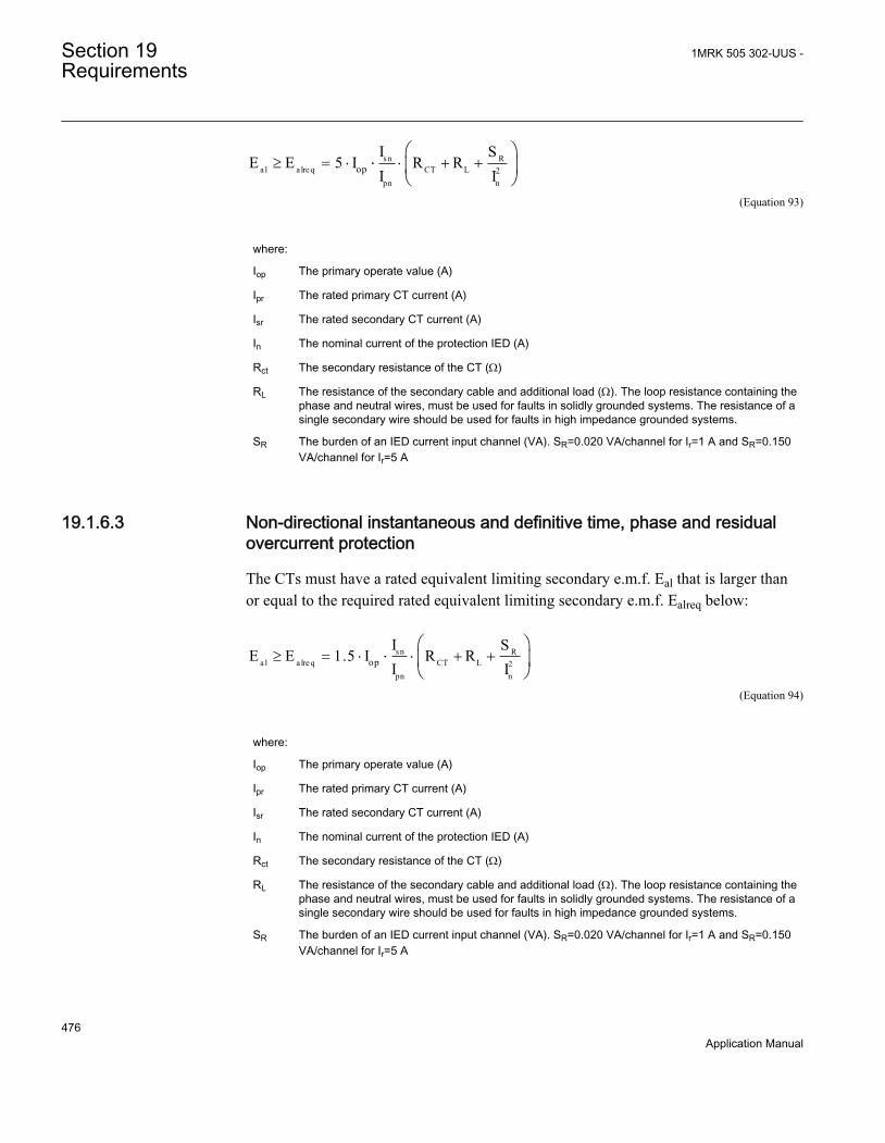
sn Ra l a lre q CT L 2
pn nop
I SE E 5 I R R
I I³ = × × + +
æ ö× ç ÷
è øEQUATION1677 V1 EN (Equation 93)
where:
Iop The primary operate value (A)
Ipr The rated primary CT current (A)
Isr The rated secondary CT current (A)
In The nominal current of the protection IED (A)
Rct The secondary resistance of the CT (W)
RL The resistance of the secondary cable and additional load (W). The loop resistance containing thephase and neutral wires, must be used for faults in solidly grounded systems. The resistance of asingle secondary wire should be used for faults in high impedance grounded systems.
SR The burden of an IED current input channel (VA). SR=0.020 VA/channel for Ir=1 A and SR=0.150VA/channel for Ir=5 A
19.1.6.3 Non-directional instantaneous and definitive time, phase and residualovercurrent protection
The CTs must have a rated equivalent limiting secondary e.m.f. Eal that is larger thanor equal to the required rated equivalent limiting secondary e.m.f. Ealreq below:
sn Ra l a lre q CT L 2
pn nop
I SE E 1.5 I R R
I I³ = × × + +
æ ö× ç ÷
è øEQUATION1678 V1 EN (Equation 94)
where:
Iop The primary operate value (A)
Ipr The rated primary CT current (A)
Isr The rated secondary CT current (A)
In The nominal current of the protection IED (A)
Rct The secondary resistance of the CT (W)
RL The resistance of the secondary cable and additional load (W). The loop resistance containing thephase and neutral wires, must be used for faults in solidly grounded systems. The resistance of asingle secondary wire should be used for faults in high impedance grounded systems.
SR The burden of an IED current input channel (VA). SR=0.020 VA/channel for Ir=1 A and SR=0.150VA/channel for Ir=5 A
Section 19 1MRK 505 302-UUS -Requirements
476Application Manual

19.1.6.4 Non-directional inverse time delayed phase and residual overcurrentprotection
The requirement according to Equation 95 and Equation 96 does not need to befulfilled if the high set instantaneous or definitive time stage is used. In this caseEquation 94 is the only necessary requirement.
If the inverse time delayed function is the only used overcurrent protection function theCTs must have a rated equivalent limiting secondary e.m.f. Eal that is larger than orequal to the required rated equivalent limiting secondary e.m.f. Ealreq below:
sn Ra l a lre q CT L 2
pn nop
I SE E 20 I R R
I I³ = × × + +
æ ö× ç ÷
è øEQUATION1679 V1 EN (Equation 95)
where
Iop The primary current set value of the inverse time function (A)
Ipr The rated primary CT current (A)
Isr The rated secondary CT current (A)
In The nominal current of the protection IED (A)
Rct The secondary resistance of the CT (W)
RL The resistance of the secondary cable and additional load (W). The loopresistance containing the phase and neutral wires, must be used for faults insolidly grounded systems. The resistance of a single secondary wire should beused for faults in high impedance grounded systems.
SR The burden of an IED current input channel (VA). SR=0.020 VA/channel for Ir=1A and SR=0.150 VA/channel for Ir=5 A
Independent of the value of Iop the maximum required Eal is specified according to thefollowing:
s n Ra l a lre q max CT L 2
pn nk ma x
I SE E I R R
I I³ = × + +
æ ö× ç ÷
è øEQUATION1680 V1 EN (Equation 96)
where
Ikmax Maximum primary fundamental frequency current for close-in faults (A)
1MRK 505 302-UUS - Section 19Requirements
477Application Manual
19.1.7 Current transformer requirements for CTs according to otherstandardsAll kinds of conventional magnetic core CTs are possible to use with the IEDs if theyfulfill the requirements corresponding to the above specified expressed as the ratedequivalent limiting secondary e.m.f. Eal according to the IEC 61869-2 standard. Fromdifferent standards and available data for relaying applications it is possible toapproximately calculate a secondary e.m.f. of the CT comparable with Eal. Bycomparing this with the required rated equivalent limiting secondary e.m.f. Ealreq it ispossible to judge if the CT fulfills the requirements. The requirements according tosome other standards are specified below.
19.1.7.1 Current transformers according to IEC 61869-2, class P, PR
A CT according to IEC 61869-2 is specified by the secondary limiting e.m.f. Ealf. Thevalue of the Ealf is approximately equal to the corresponding Eal. Therefore, the CTsaccording to class P and PR must have a secondary limiting e.m.f. Ealf that fulfills thefollowing:
2max alreqE max E>EQUATION1383 V3 EN (Equation 97)
19.1.7.2 Current transformers according to IEC 61869-2, class PX, PXR (and oldIEC 60044-6, class TPS and old British Standard, class X)
CTs according to these classes are specified approximately in the same way by a ratedknee point e.m.f. Eknee (Ek for class PX and PXR, EkneeBS for class X and the limitingsecondary voltage Val for TPS). The value of the Eknee is lower than the correspondingEal according to IEC 61869-2. It is not possible to give a general relation between theEknee and the Eal but normally the Eknee is approximately 80 % of the Eal. Therefore,the CTs according to class PX, PXR, X and TPS must have a rated knee point e.m.f.Eknee that fulfills the following:
(1 )= × + - ×Old CalculatedS TD S TD S
EQUATION1893.ANSI V1 EN (Equation 98)
Section 19 1MRK 505 302-UUS -Requirements
478Application Manual

19.1.7.3 Current transformers according to ANSI/IEEE
Current transformers according to ANSI/IEEE are partly specified in different ways. Arated secondary terminal voltage VANSI is specified for a CT of class C. VANSI is thesecondary terminal voltage the CT will deliver to a standard burden at 20 times ratedsecondary current without exceeding 10 % ratio correction. There are a number ofstandardized VANSI values for example, VANSI is 400 V for a C400 CT. Acorresponding rated equivalent limiting secondary e.m.f. EalANSI can be estimated asfollows:
a lANS I S N CT ANS I S N CT S N bANS IE 20 I R V 20 I R 20 I Z= × × + = × × + × ×
EQUATION1682 V1 EN (Equation 99)
where:
ZbANSI The impedance (that is, with a complex quantity) of the standard ANSI burden for the specific Cclass (W)
VANSI The secondary terminal voltage for the specific C class (V)
The CTs according to class C must have a calculated rated equivalent limitingsecondary e.m.f. EalANSI that fulfils the following:
alANSI alreqE maximum of E>
EQUATION1384 V2 EN (Equation 100)
A CT according to ANSI/IEEE is also specified by the knee point voltage VkneeANSIthat is graphically defined from an excitation curve. The knee point voltage VkneeANSInormally has a lower value than the knee-point e.m.f. according to IEC and BS.VkneeANSI can approximately be estimated to 75 % of the corresponding Eal accordingto IEC 61869-2. Therefore, the CTs according to ANSI/IEEE must have a knee pointvoltage VkneeANSI that fulfills the following:
kneeANSI alreqV 0.75 (max imum of E )> ×EQUATION2101 V2 EN (Equation 101)
The following guide may also be referred for some more application aspects of ANSIclass CTs: IEEE C37.110 (2007), IEEE Guide for the Application of CurrentTransformers Used for Protective Relaying Purposes.
1MRK 505 302-UUS - Section 19Requirements
479Application Manual
19.2 Voltage transformer requirements
The performance of a protection function will depend on the quality of the measuredinput signal. Transients caused by capacitive Coupled voltage transformers (CCVTs)can affect some protection functions.
Magnetic or capacitive voltage transformers can be used.
The capacitive voltage transformers (CCVTs) should fulfill the requirements accordingto the IEC 61869-5 standard regarding ferro-resonance and transients. The ferro-resonance requirements of the CCVTs are specified in chapter 6.502 of the standard.
The transient responses for three different standard transient response classes, T1, T2and T3 are specified in chapter 6.503 of the standard. CCVTs according to all classescan be used.
The protection IED has effective filters for these transients, which gives secure andcorrect operation with CCVTs.
19.3 SNTP server requirements
The SNTP server to be used is connected to the local network, that is not more than 4-5switches or routers away from the IED. The SNTP server is dedicated for its task, or atleast equipped with a real-time operating system, that is not a PC with SNTP serversoftware. The SNTP server should be stable, that is, either synchronized from a stablesource like GPS, or local without synchronization. Using a local SNTP server withoutsynchronization as primary or secondary server in a redundant configuration is notrecommended.
Section 19 1MRK 505 302-UUS -Requirements
480Application Manual

Section 20 Glossary
AC Alternating current
ACC Actual channel
ACT Application configuration tool within PCM600
A/D converter Analog-to-digital converter
ADBS Amplitude deadband supervision
ADM Analog digital conversion module, with time synchronization
AI Analog input
ANSI American National Standards Institute
AR Autoreclosing
ASCT Auxiliary summation current transformer
ASD Adaptive signal detection
ASDU Application service data unit
AWG American Wire Gauge standard
BBP Busbar protection
BFOC/2,5 Bayonet fibre optic connector
BFP Breaker failure protection
BI Binary input
BIM Binary input module
BOM Binary output module
BOS Binary outputs status
BR External bistable relay
BS British Standards
BSR Binary signal transfer function, receiver blocks
BST Binary signal transfer function, transmit blocks
C37.94 IEEE/ANSI protocol used when sending binary signalsbetween IEDs
CAN Controller Area Network. ISO standard (ISO 11898) for serialcommunication
1MRK 505 302-UUS - Section 20Glossary
481Application Manual
CB Circuit breaker
CBM Combined backplane module
CCITT Consultative Committee for International Telegraph andTelephony. A United Nations-sponsored standards bodywithin the International Telecommunications Union.
CCM CAN carrier module
CCVT Capacitive Coupled Voltage Transformer
Class C Protection Current Transformer class as per IEEE/ ANSI
CMPPS Combined megapulses per second
CMT Communication Management tool in PCM600
CO cycle Close-open cycle
Codirectional Way of transmitting G.703 over a balanced line. Involves twotwisted pairs making it possible to transmit information inboth directions
COM Command
COMTRADE Standard Common Format for Transient Data Exchangeformat for Disturbance recorder according to IEEE/ANSIC37.111, 1999 / IEC60255-24
Contra-directional Way of transmitting G.703 over a balanced line. Involves fourtwisted pairs, two of which are used for transmitting data inboth directions and two for transmitting clock signals
COT Cause of transmission
CPU Central processing unit
CR Carrier receive
CRC Cyclic redundancy check
CROB Control relay output block
CS Carrier send
CT Current transformer
CU Communication unit
CVT or CCVT Capacitive voltage transformer
DAR Delayed autoreclosing
DARPA Defense Advanced Research Projects Agency (The USdeveloper of the TCP/IP protocol etc.)
DBDL Dead bus dead line
Section 20 1MRK 505 302-UUS -Glossary
482Application Manual

DBLL Dead bus live line
DC Direct current
DFC Data flow control
DFT Discrete Fourier transform
DHCP Dynamic Host Configuration Protocol
DIP-switch Small switch mounted on a printed circuit board
DI Digital input
DLLB Dead line live bus
DNP Distributed Network Protocol as per IEEE Std 1815-2012
DR Disturbance recorder
DRAM Dynamic random access memory
DRH Disturbance report handler
DSP Digital signal processor
DTT Direct transfer trip scheme
EHV network Extra high voltage network
EIA Electronic Industries Association
EMC Electromagnetic compatibility
EMF Electromotive force
EMI Electromagnetic interference
EnFP End fault protection
EPA Enhanced performance architecture
ESD Electrostatic discharge
F-SMA Type of optical fibre connector
FAN Fault number
FCB Flow control bit; Frame count bit
FOX 20 Modular 20 channel telecommunication system for speech,data and protection signals
FOX 512/515 Access multiplexer
FOX 6Plus Compact time-division multiplexer for the transmission of upto seven duplex channels of digital data over optical fibers
FUN Function type
1MRK 505 302-UUS - Section 20Glossary
483Application Manual

G.703 Electrical and functional description for digital lines used bylocal telephone companies. Can be transported over balancedand unbalanced lines
GCM Communication interface module with carrier of GPS receivermodule
GDE Graphical display editor within PCM600
GI General interrogation command
GIS Gas-insulated switchgear
GOOSE Generic object-oriented substation event
GPS Global positioning system
GSAL Generic security application
GTM GPS Time Module
HDLC protocol High-level data link control, protocol based on the HDLCstandard
HFBR connector type Plastic fiber connector
HMI Human-machine interface
HSAR High speed autoreclosing
HV High-voltage
HVDC High-voltage direct current
IDBS Integrating deadband supervision
IEC International Electrical Committee
IEC 60044-6 IEC Standard, Instrument transformers – Part 6: Requirementsfor protective current transformers for transient performance
IEC 60870-5-103 Communication standard for protection equipment. A serialmaster/slave protocol for point-to-point communication
IEC 61850 Substation automation communication standard
IEC 61850–8–1 Communication protocol standard
IEEE Institute of Electrical and Electronics Engineers
IEEE 802.12 A network technology standard that provides 100 Mbits/s ontwisted-pair or optical fiber cable
IEEE P1386.1 PCI Mezzanine Card (PMC) standard for local bus modules.References the CMC (IEEE P1386, also known as CommonMezzanine Card) standard for the mechanics and the PCIspecifications from the PCI SIG (Special Interest Group) forthe electrical EMF (Electromotive force).
Section 20 1MRK 505 302-UUS -Glossary
484Application Manual
IEEE 1686 Standard for Substation Intelligent Electronic Devices (IEDs)Cyber Security Capabilities
IED Intelligent electronic device
I-GIS Intelligent gas-insulated switchgear
IOM Binary input/output module
Instance When several occurrences of the same function are availablein the IED, they are referred to as instances of that function.One instance of a function is identical to another of the samekind but has a different number in the IED user interfaces.The word "instance" is sometimes defined as an item ofinformation that is representative of a type. In the same wayan instance of a function in the IED is representative of a typeof function.
IP 1. Internet protocol. The network layer for the TCP/IPprotocol suite widely used on Ethernet networks. IP is aconnectionless, best-effort packet-switching protocol. Itprovides packet routing, fragmentation and reassemblythrough the data link layer.2. Ingression protection, according to IEC 60529
IP 20 Ingression protection, according to IEC 60529, levelIP20- Protected against solid foreign objects of 12.5mmdiameter and greater.
IP 40 Ingression protection, according to IEC 60529, level IP40-Protected against solid foreign objects of 1mm diameter andgreater.
IP 54 Ingression protection, according to IEC 60529, levelIP54-Dust-protected, protected against splashing water.
IRF Internal failure signal
IRIG-B: InterRange Instrumentation Group Time code format B,standard 200
ITU International Telecommunications Union
LAN Local area network
LIB 520 High-voltage software module
LCD Liquid crystal display
LDCM Line differential communication module
LDD Local detection device
LED Light-emitting diode
1MRK 505 302-UUS - Section 20Glossary
485Application Manual

LNT LON network tool
LON Local operating network
MCB Miniature circuit breaker
MCM Mezzanine carrier module
MIM Milli-ampere module
MPM Main processing module
MVAL Value of measurement
MVB Multifunction vehicle bus. Standardized serial bus originallydeveloped for use in trains.
NCC National Control Centre
NOF Number of grid faults
NUM Numerical module
OCO cycle Open-close-open cycle
OCP Overcurrent protection
OEM Optical Ethernet module
OLTC On-load tap changer
OTEV Disturbance data recording initiated by other event than start/pick-up
OV Overvoltage
Overreach A term used to describe how the relay behaves during a faultcondition. For example, a distance relay is overreaching whenthe impedance presented to it is smaller than the apparentimpedance to the fault applied to the balance point, that is, theset reach. The relay “sees” the fault but perhaps it should nothave seen it.
PCI Peripheral component interconnect, a local data bus
PCM Pulse code modulation
PCM600 Protection and control IED manager
PC-MIP Mezzanine card standard
PMC PCI Mezzanine card
POR Permissive overreach
POTT Permissive overreach transfer trip
Process bus Bus or LAN used at the process level, that is, in nearproximity to the measured and/or controlled components
Section 20 1MRK 505 302-UUS -Glossary
486Application Manual

PSM Power supply module
PST Parameter setting tool within PCM600
PT ratio Potential transformer or voltage transformer ratio
PUTT Permissive underreach transfer trip
RASC Synchrocheck relay, COMBIFLEX
RCA Relay characteristic angle
RISC Reduced instruction set computer
RMS value Root mean square value
RS422 A balanced serial interface for the transmission of digital datain point-to-point connections
RS485 Serial link according to EIA standard RS485
RTC Real-time clock
RTU Remote terminal unit
SA Substation Automation
SBO Select-before-operate
SC Switch or push button to close
SCL Short circuit location
SCS Station control system
SCADA Supervision, control and data acquisition
SCT System configuration tool according to standard IEC 61850
SDU Service data unit
SLM Serial communication module.
SMA connector Subminiature version A, A threaded connector with constantimpedance.
SMT Signal matrix tool within PCM600
SMS Station monitoring system
SNTP Simple network time protocol – is used to synchronizecomputer clocks on local area networks. This reduces therequirement to have accurate hardware clocks in everyembedded system in a network. Each embedded node caninstead synchronize with a remote clock, providing therequired accuracy.
SOF Status of fault
1MRK 505 302-UUS - Section 20Glossary
487Application Manual

SPA Strömberg Protection Acquisition (SPA), a serial master/slaveprotocol for point-to-point communication
SRY Switch for CB ready condition
ST Switch or push button to trip
Starpoint Neutral/Wye point of transformer or generator
SVC Static VAr compensation
TC Trip coil
TCS Trip circuit supervision
TCP Transmission control protocol. The most common transportlayer protocol used on Ethernet and the Internet.
TCP/IP Transmission control protocol over Internet Protocol. The defacto standard Ethernet protocols incorporated into 4.2BSDUnix. TCP/IP was developed by DARPA for Internet workingand encompasses both network layer and transport layerprotocols. While TCP and IP specify two protocols at specificprotocol layers, TCP/IP is often used to refer to the entire USDepartment of Defense protocol suite based upon these,including Telnet, FTP, UDP and RDP.
TEF Time delayed gound-fault protection function
TM Transmit (disturbance data)
TNC connector Threaded Neill-Concelman, a threaded constant impedanceversion of a BNC connector
TP Trip (recorded fault)
TPZ, TPY, TPX, TPS Current transformer class according to IEC
TRM Transformer Module. This module transforms currents andvoltages taken from the process into levels suitable for furthersignal processing.
TYP Type identification
UMT User management tool
Underreach A term used to describe how the relay behaves during a faultcondition. For example, a distance relay is underreachingwhen the impedance presented to it is greater than theapparent impedance to the fault applied to the balance point,that is, the set reach. The relay does not “see” the fault butperhaps it should have seen it. See also Overreach.
UTC Coordinated Universal Time. A coordinated time scale,maintained by the Bureau International des Poids et Mesures
Section 20 1MRK 505 302-UUS -Glossary
488Application Manual

(BIPM), which forms the basis of a coordinated disseminationof standard frequencies and time signals. UTC is derived fromInternational Atomic Time (TAI) by the addition of a wholenumber of "leap seconds" to synchronize it with UniversalTime 1 (UT1), thus allowing for the eccentricity of the Earth'sorbit, the rotational axis tilt (23.5 degrees), but still showingthe Earth's irregular rotation, on which UT1 is based. TheCoordinated Universal Time is expressed using a 24-hourclock, and uses the Gregorian calendar. It is used foraeroplane and ship navigation, where it is also sometimesknown by the military name, "Zulu time." "Zulu" in thephonetic alphabet stands for "Z", which stands for longitudezero.
UV Undervoltage
WEI Weak end infeed logic
VT Voltage transformer
X.21 A digital signalling interface primarily used for telecomequipment
3IO Three times zero-sequence current.Often referred to as theresidual or the ground-fault current
3VO Three times the zero sequence voltage. Often referred to asthe residual voltage or the neutral point voltage
1MRK 505 302-UUS - Section 20Glossary
489Application Manual

490

491

Contact us
ABB ABSubstation Automation ProductsSE-721 59 Västerås, SwedenPhone +46 (0) 21 32 50 00Fax +46 (0) 21 14 69 18
www.abb.com/substationautomation
1MR
K 5
05 3
02-U
US
-©
Cop
yrig
ht 2
014
AB
B. A
ll rig
hts
rese
rved
.