Application-driven Development of Flexible Packet-oriented ...
176
Technische Universit¨ at M¨ unchen Lehrstuhl f¨ ur Integrierte Systeme Application-driven Development of Flexible Packet-oriented Communication Interfaces Christian Sauer Vollst¨ andiger Abdruck der von der Fakult¨ at f¨ ur Elektrotechnik und Informationstechnik der Technischen Universit¨ at M¨ unchen zur Erlangung des akademischen Grades eines Doktor-Ingenieurs (Dr.-Ing.) genehmigten Dissertation. Vorsitzender: Univ.-Prof. Dr.-Ing. Ulf Schlichtmann Pr¨ ufer der Dissertation: 1. Univ.-Prof. Dr. sc. techn. Andreas Herkersdorf 2. Prof. Kurt Keutzer, Ph.D. (University of California, Berkeley, USA) Die Dissertation wurde am 2.6.2009 bei der Technischen Universit¨ at M¨ unchen eingereicht und durch die Fakult¨ at f¨ ur Elektrotechnik und Informationstechnik am 13.7.2010 angenommen.
Transcript of Application-driven Development of Flexible Packet-oriented ...

Technische Universitat MunchenLehrstuhl fur Integrierte Systeme
Application-driven Development of Flexible
Packet-oriented Communication Interfaces
Christian Sauer
Vollstandiger Abdruck der von der Fakultat fur Elektrotechnik undInformationstechnik der Technischen Universitat Munchen zur Erlangung
des akademischen Grades eines
Doktor-Ingenieurs (Dr.-Ing.)
genehmigten Dissertation.
Vorsitzender:
Univ.-Prof. Dr.-Ing. Ulf Schlichtmann
Prufer der Dissertation:
1. Univ.-Prof. Dr. sc. techn. Andreas Herkersdorf
2. Prof. Kurt Keutzer, Ph.D. (University of California, Berkeley, USA)
Die Dissertation wurde am 2.6.2009 bei der Technischen Universitat Muncheneingereicht und durch die Fakultat fur Elektrotechnik und
Informationstechnik am 13.7.2010 angenommen.


Contents
1 Introduction 11.1 The reality of the interface zoo . . . . . . . . . . . . . . . . . . . 11.2 The promise of flexible interfaces . . . . . . . . . . . . . . . . . . 41.3 Leveraging the programmable platform . . . . . . . . . . . . . . . 61.4 Objectives of research . . . . . . . . . . . . . . . . . . . . . . . . 71.5 Structure of this dissertation . . . . . . . . . . . . . . . . . . . . 8
2 Review of Communication Interfaces 92.1 Application domains . . . . . . . . . . . . . . . . . . . . . . . . . 92.2 Usage-based classification . . . . . . . . . . . . . . . . . . . . . . 102.3 Interfaces deployed with network processors . . . . . . . . . . . . 112.4 Residential gateways & integrated access devices . . . . . . . . . 142.5 Wireless application processors . . . . . . . . . . . . . . . . . . . 182.6 Discussion and selection of interfaces . . . . . . . . . . . . . . . . 20
3 Analysis of Packet Interfaces 253.1 Fundamentals . . . . . . . . . . . . . . . . . . . . . . . . . . . . . 25
3.1.1 Interface surroundings . . . . . . . . . . . . . . . . . . . . 253.1.2 Functional layers . . . . . . . . . . . . . . . . . . . . . . . 263.1.3 Elementary tasks . . . . . . . . . . . . . . . . . . . . . . . 27
3.2 Modeling packet-based interfaces in Click . . . . . . . . . . . . . 293.2.1 Click characteristics . . . . . . . . . . . . . . . . . . . . . 293.2.2 Interface specifics . . . . . . . . . . . . . . . . . . . . . . . 303.2.3 Model setup . . . . . . . . . . . . . . . . . . . . . . . . . . 31
3.3 Application models . . . . . . . . . . . . . . . . . . . . . . . . . . 323.3.1 PCI Express model . . . . . . . . . . . . . . . . . . . . . . 323.3.2 RapidIO model . . . . . . . . . . . . . . . . . . . . . . . . 343.3.3 Hypertransport model . . . . . . . . . . . . . . . . . . . . 343.3.4 Gigabit Ethernet model . . . . . . . . . . . . . . . . . . . 363.3.5 Wireless LAN model . . . . . . . . . . . . . . . . . . . . . 38
3.4 Related work . . . . . . . . . . . . . . . . . . . . . . . . . . . . . 413.4.1 Comparing protocols . . . . . . . . . . . . . . . . . . . . . 413.4.2 Modeling packet processing applications . . . . . . . . . . 42
3.5 Comparison and conclusion . . . . . . . . . . . . . . . . . . . . . 47
i
ii CONTENTS
4 An Application-driven Methodology 514.1 Requirements . . . . . . . . . . . . . . . . . . . . . . . . . . . . . 514.2 Methodology fundamentals . . . . . . . . . . . . . . . . . . . . . 53
4.2.1 SystemC modeling and performance evaluation . . . . . . 534.2.2 Click extensions for specific architectures . . . . . . . . . 544.2.3 Common Y-chart methodology . . . . . . . . . . . . . . . 554.2.4 Evaluation frameworks based on the Y-chart . . . . . . . 56
4.3 Application-driven flow using the Y-chart . . . . . . . . . . . . . 594.3.1 Five phase methodology . . . . . . . . . . . . . . . . . . . 594.3.2 Prerequisites and tools . . . . . . . . . . . . . . . . . . . . 61
4.4 Code generation for embedded cores . . . . . . . . . . . . . . . . 634.4.1 Why not Click for embedded processors? . . . . . . . . . 634.4.2 CRACC – Click Rapidly adapted to C Code . . . . . . . 644.4.3 Targeting CRACC to embedded cores . . . . . . . . . . . 66
4.5 Hardware encapsulation, platform mapping . . . . . . . . . . . . 674.5.1 Packet I/O . . . . . . . . . . . . . . . . . . . . . . . . . . 674.5.2 Special purpose hardware . . . . . . . . . . . . . . . . . . 684.5.3 Inter-element communication . . . . . . . . . . . . . . . . 684.5.4 Data layout and distinct memories . . . . . . . . . . . . . 694.5.5 Mapping annotation and multi core code generation . . . 70
4.6 NOVA - A Network-Optimized Versatile Architecture . . . . . . 724.6.1 NOVA hardware platform . . . . . . . . . . . . . . . . . . 724.6.2 Programming model . . . . . . . . . . . . . . . . . . . . . 744.6.3 Platform evaluation . . . . . . . . . . . . . . . . . . . . . 764.6.4 Remarks . . . . . . . . . . . . . . . . . . . . . . . . . . . . 76
4.7 SystemClick – Performance models in SystemC . . . . . . . . . . 774.7.1 Platform representation . . . . . . . . . . . . . . . . . . . 774.7.2 Performance annotation . . . . . . . . . . . . . . . . . . . 784.7.3 Embedding Click in SystemC . . . . . . . . . . . . . . . . 804.7.4 Resource managers . . . . . . . . . . . . . . . . . . . . . . 824.7.5 Statistics . . . . . . . . . . . . . . . . . . . . . . . . . . . 84
4.8 Quality of Results . . . . . . . . . . . . . . . . . . . . . . . . . . 854.8.1 Simulation performance . . . . . . . . . . . . . . . . . . . 864.8.2 Simulation accuracy . . . . . . . . . . . . . . . . . . . . . 87
4.9 Chapter summary and conclusion . . . . . . . . . . . . . . . . . . 87
5 A Programmable Interface Architecture 895.1 Fully programmable solution . . . . . . . . . . . . . . . . . . . . 90
5.1.1 Architecture setup . . . . . . . . . . . . . . . . . . . . . . 905.1.2 Profiling results . . . . . . . . . . . . . . . . . . . . . . . . 915.1.3 Performance analysis . . . . . . . . . . . . . . . . . . . . . 945.1.4 Observations . . . . . . . . . . . . . . . . . . . . . . . . . 97
5.2 Design trade-offs and consequences . . . . . . . . . . . . . . . . . 975.2.1 Core type and configuration . . . . . . . . . . . . . . . . . 985.2.2 Application-specific hardware accelerators . . . . . . . . . 995.2.3 Application-specific vs. general purpose ISA . . . . . . . . 1015.2.4 Multiple processors . . . . . . . . . . . . . . . . . . . . . . 1055.2.5 Communication Topology . . . . . . . . . . . . . . . . . . 112
5.3 Proposal for an optimized architecture . . . . . . . . . . . . . . . 1165.3.1 Block diagram . . . . . . . . . . . . . . . . . . . . . . . . 116

CONTENTS iii
5.3.2 Hardware building blocks . . . . . . . . . . . . . . . . . . 1175.3.3 Synthesis results and cost estimation . . . . . . . . . . . . 1195.3.4 Performance & further optimization potential . . . . . . . 121
5.4 Costs of modularity and programmability . . . . . . . . . . . . . 1235.4.1 Hardware modularity . . . . . . . . . . . . . . . . . . . . 1235.4.2 Software modularity . . . . . . . . . . . . . . . . . . . . . 1245.4.3 A less modular architecture experiment . . . . . . . . . . 125
5.5 Related work . . . . . . . . . . . . . . . . . . . . . . . . . . . . . 1295.5.1 Modular platform architectures . . . . . . . . . . . . . . . 1295.5.2 Flexible interface implementations . . . . . . . . . . . . . 1315.5.3 Complexity of individual protocol implementations . . . . 134
5.6 Chapter summary and discussion . . . . . . . . . . . . . . . . . . 136
6 Conclusion 1436.1 Application-driven methodology . . . . . . . . . . . . . . . . . . . 1446.2 Architecture exploration . . . . . . . . . . . . . . . . . . . . . . . 1456.3 Is a programmable solution feasible? . . . . . . . . . . . . . . . . 1466.4 Directions for further research . . . . . . . . . . . . . . . . . . . . 147
Bibliography 149

iv CONTENTS

List of Figures
1.1 IXP1200 die photograph . . . . . . . . . . . . . . . . . . . . . . . 21.2 Nexperia die photograph . . . . . . . . . . . . . . . . . . . . . . . 21.3 Area increase in PCI protocol versions . . . . . . . . . . . . . . . 31.4 Bandwidth vs.pin count of recent network processor interfaces. . 41.5 Processing core topologies in MPSoC platforms. . . . . . . . . . . 61.6 MPSoC platform with programmable IO elements . . . . . . . . 7
2.1 Interfaces and deployment of network processors on line cards . . 112.2 Exemplary interfaces of residential gateways . . . . . . . . . . . . 15
3.1 A communication interface and its environment. . . . . . . . . . 263.2 Layers of a packet-oriented communication interface . . . . . . . 273.3 Click example: graphical and textual representations. . . . . . . 303.4 Basic simulation setup for point-to-point communication . . . . . 313.5 Simulation setup for shared communication channels . . . . . . . 313.6 PCI-Express end-point device interface model. . . . . . . . . . . 323.7 Hypertransport end-point device interface model. . . . . . . . . . 353.8 Gigabit Ethernet MAC and PHY (1000Base-X) model. . . . . . . 373.9 Model of an 802.11 a/b/g wireless LAN station with QoS . . . . 393.10 Atomic data frame transfer (IEEE 802.11). . . . . . . . . . . . . 41
4.1 The Y-chart methodology for design space exploration. . . . . . . 554.2 The Y-chart based on CRACC and NOVA. . . . . . . . . . . . . 624.3 The Y-chart based on SystemClick performance models. . . . . . 624.4 The CRACC code generation flow and framework. . . . . . . . . 644.5 Mapping a Click application onto a concurrent platform. . . . . . 684.6 Synthesis of push communication wrappers for a push target. . . 704.7 Synthesis of pull-to-push communication wrappers. . . . . . . . . 704.8 Notifying pull communication wrappers for a push target. . . . . 704.9 NOVA’s socket concept. . . . . . . . . . . . . . . . . . . . . . . . 734.10 Encapsulation of a core with subsystem by NOVA’s socket . . . . 744.11 NOVA prototype with four processing elements. . . . . . . . . . . 764.12 SystemClick - SystemC performance models from Click source . 774.13 Representation of an application-architecture mapping . . . . . . 784.14 Entry and Exit points of a Click element . . . . . . . . . . . . . . 794.15 Generated SystemClick wrappers integrate Click in SystemC . . 814.16 Simulation time synchronization at points of IO . . . . . . . . . . 824.17 Difference in IO packet statistics . . . . . . . . . . . . . . . . . . 85
v

vi LIST OF FIGURES
5.1 Fully programmable single-core architecture . . . . . . . . . . . . 905.2 Instruction counts per wLAN processing path . . . . . . . . . . . 935.3 Clock frequency requirements over packet size for PCI Express . 955.4 Clock frequency requirements over packet size for 11g wLAN . . 955.5 MAC time budget for response frames. . . . . . . . . . . . . . . . 965.6 Core comparison (packet processing performance vs. area) . . . . 985.7 Frequency impact of DMA and CRC accelerators for PEX . . . . 1005.8 Frequency impact of DMA, CRC, WEP for wLAN . . . . . . . . 1015.9 Instruction histogram for the flow control element . . . . . . . . 1035.10 PEX cycle requirements with & without customized ISA . . . . . 1055.11 Frequency impact of an application-specific ISA for PCI Express 1055.12 Speedups for PCI Express in pooled and pipelined MP settings . 1075.13 Partitioning of the PCI Express model for the MP simulation. . . 1095.14 Utilization for different PCI Express mappings. . . . . . . . . . . 1105.15 wLAN response time distributions for 1 and 2 core mappings . . 1135.16 Rel. throughput and bus utilization (4PE standard mapping) . . 1145.17 Rel. throughput and bus utilization (optimized 4PE mapping) . 1145.18 Rel. performance over IO box sizes at 20% bus speed . . . . . . . 1155.19 Backlog along the processing path for different designs . . . . . . 1165.20 Block diagram of the optimized 4-core architecture . . . . . . . . 1175.21 Relative area overhead of the NOVA Ethernet IO socket. . . . . . 1245.22 Overhead of modular software. . . . . . . . . . . . . . . . . . . . 1255.23 Specialized GbE SoftMac architecture. . . . . . . . . . . . . . . . 126

List of Tables
2.1 Network processors and their I/O interfaces. . . . . . . . . . . . . 122.2 Interfaces of residential gateways and integrated access devices. . 162.3 Interfaces of wireless application processors. . . . . . . . . . . . . 192.4 Number of different interfaces per SoC and domain. . . . . . . . 212.5 Essential set of deployed communication interfaces. . . . . . . . . 21
3.1 Tasks on protocol layers for the different interfaces. . . . . . . . . 483.2 Packet processing paths for different IO interface models. . . . . 48
4.1 Overview of Y-chart-based design space exploration frameworks . 594.2 Relative simulation speed for two benchmarks . . . . . . . . . . . 864.3 SystemClick accuracy: Total number of instructions . . . . . . . 87
5.1 Single packet instruction counts for the PCI express model. . . . 925.2 Single packet instruction counts for the wireless LAN model. . . 925.3 Instruction counts for task handling and packet IO. . . . . . . . . 945.4 Required clock frequency for wLAN responses in realtime . . . . 965.5 Profile for PCI-Express Click elements. . . . . . . . . . . . . . . . 1045.6 Partitioning of the most critical PCI Express task chain. . . . . . 1115.7 Refined PCI Express partitioning using 3, 4, and 5 Tx cores . . . 1125.8 Area requirements of the General Purpose PE. . . . . . . . . . . 1205.9 Area footprint of the NOVA Ethernet IO module. . . . . . . . . . 1205.10 Area requirements of the specialized PE module. . . . . . . . . . 1215.11 Area requirements for different sizes of code and data memory . 1215.12 Area of the processor-based GbE compared to NOVA’s version . 1275.13 Published sizes of IO interface for Xlinx FPGAs . . . . . . . . . 1355.14 Resource breakdown of a GbE hardware controller. . . . . . . . . 136
vii

viii LIST OF TABLES

Acknowledgements
Without the support and advice of my colleagues and students this disserta-tion would not have been possible. Over the years, many of them have be-come friends. At UC Berkeley, I would like to thank Michael Shilman, ScottWeber, Andrew Mihal, Niraj Shah, Matt Moskewicz, Will Plishker, KaushikRavidran, N.R. Satish, Jose-Ignacio Gomez, Jorn Janneck, Chidamber Kulka-rni, and Matthias Gries. At Infineon in Munich, I thank Matthias Gries (oncemore), Andreas Grafe, Milena Dimitrova, Soren Sonntag, Sebastian Dirk, Hans-Peter Lob, Xiaoyan Jia, Winthir Brunnbauer, Chinapirom Teerapat, and Hans-Martin Bluthgen.
There have been collaborations that came to life through the people execut-ing them. My thanks go to Jorg-Christian Niemann, Mario Pormann, ChristianLiss, Ulrich Ruckert (all at U Paderborn), Dietmar Tolle, Bo Wu, Helmut Steck-enbiller, Rudi Knorr (at FhG Munich), Daniel Lorente, and Thomas Wild (atTU Munich).
Infineon Technologies consistently supported my research. I especially thankmy superiors Ulrich Ramacher (Corporate Research) and Friedrich Geissler(Communication Solutions) for their enthusiasm and interest.
I thank my advisors Kurt Keutzer at UC Berkeley, and also Andreas Herk-ersdorf at TU Munich, for sharing their experience and wisdom.
But most of all, I would like to thank my wife Katja for standing by me withher unending patience and love.
ix


Chapter 1
Introduction
Rapid progress in embedded systems such as network-connected informationappliances has given new impetus to a wide and rapidly growing range of input-output (I/O) communication standards such as PCI Express, USB, and IEEE802.11. This in turn has resulted in system architectures combining customizedblocks for communication interfaces with programmable processor cores. Pro-cessors, memory hierarchies, interconnection networks, communication inter-faces and other peripherals are the main building blocks for these application-specific programmable system-on-a-chip architectures.
During the design process a great deal of emphasis is placed on the first threebuilding block types but communication interfaces and other peripherals areoften neglected. This is mainly due to the general perception that these modulesconstitute standard intellectual property (IP) blocks that can be integratedquickly at design time.
However, due to their heterogeneity and ad-hoc integration practice thesemodules are increasingly becoming bottlenecks to both the design process andthe complexity of the end system as will be discussed below.
1.1 The reality of the interface zoo
We define communication interfaces as system-on-chip building blocks which areconnected to the pins of the chip. Auxiliary functions that primarily supportthe interaction between the communication interface and the core system suchas a direct memory access (DMA) controllers are also included.
A large amount of effort is put in processors, memories, and on-chip intercon-nect during the SoC design process whereas communication interfaces are oftenneglected and their complexity underestimated. They are perceived as standardintellectual property to be acquired as needed. These blocks are therefore inte-grated into the system-on-chip separately and relatively late during the designprocess.
Contrary to common perception, communication interfaces play a significantrole in contemporary SoCs as illustrated by two representative systems.
The first, Intel’s IXP1200 network processor, is shown in Figure 1.1. Theconcurrent and heterogeneous multiprocessor system is aimed at processingpackets in network nodes at wire speed. Its die photograph (taken from [60])
1

2 CHAPTER 1. INTRODUCTION
identifies the individual building blocks. The system comprises six RISC-likeprocessing cores (Microengines) that perform the majority of the network pro-cessing tasks, a supervising processor for control and maintenance tasks (Stron-gARM), and a set of dedicated communication interfaces for different purposes(SRAM, SDRAM, PCI, and IX-Bus). All these building blocks are connectedby a diverse on-chip network consisting of multiple buses and point-to-pointconnections.
Figure 1.1: IXP1200 die photograph [60].
Figure 1.2: Nexperia die photograph [44].
The other example is the Philips Viper system (Fig. 1.2) that targets digitalset-top boxes and residential gateways. The system contains a MIPS process-ing core (PR9340) for standard tasks and the Trimedia VLIW (TM32) core foraudio and video processing. The VLIW core is supported by several coproces-sors for 2D rendering, MPEG2 encode/decode, and video processing. In the die

1.1. THE REALITY OF THE INTERFACE ZOO 3
photograph the Firewire interface (IEEE1394) is identifiable. Other peripheralsare grouped together into larger structures. According to [44], the Viper sys-tem implements a total of 50 peripherals and accelerators in 82 different clockdomains.From these two examples it is already evident that:
• Interfaces account for a significant share of the total system, which inthese examples amounts to roughly 1/3rd to 2/3rd of the die areas.
• There are a number of different communication interfaces integrated sep-arately on one SoC.
• Individual interfaces such as the PCI interface in Figure 1.1 or the Firewireinterface (IEEE 1394) in Figure 1.2 can be quite large compared to otherstructures on the die, especially the microengines.
Two trends in evolving communication protocols aggravate the listed obser-vations: (1) the complexity of interfaces is increasing, and (2) the protocollandscape is becoming more diverse.
Due to the increasing bandwidth and more sophisticated communicationprotocols, the complexity of communication interfaces increases over time. InFigure 1.3, the interface sizes are shown for different PCI protocol versions(adapted from [28]). The most recent PCI Express interface is 3.6 times largerthan the version that was used for the Intel network processor in Figure 1.1while its performance in terms of bandwidth/pin increases by 64X (cf. Fig 1.4).
3.6
PCI v1.1
1.00.5
PCI v2.2 PCI-X 1.0 PCI Express
Figure 1.3: Relative increase in interface area for different PCI protocol stan-dards (Scaled to identical technology).
At the same time, the landscape of communication protocols is becomingmore diverse. Recently announced new and existing enhancements to severalpacket-oriented link-to-link communication protocols, for instance, are all aimedat network processors. It is, however, unclear, which of these protocols shouldbe supported. Not only do these standards represent different market alliances,but they also provide (or will provide as they evolve) comparable features ata similar performance/cost ratio, as Figure 1.4 illustrates. The figure uses thepin count for cost indication since communication centric systems tend to bedominated by IO pins.
Furthermore, the software interface for such communication interfaces, whichcomprises device drivers and often the related protocol management, is becom-

4 CHAPTER 1. INTRODUCTION
datapath width [bits]
0
4
8
16
32
64
128
1 2 4 8 16 32 64
PCI Express
HypertransportSPI-5
2
RapidIO (serial)
128
RapidIO (serial)
peak
dat
a ra
te [G
b/s]
PCI - 66MHz
PCI–X 1.0
SPI-4.2
RapidIO
(parallel)CSIX-L1
SPI-4.1
PCI–X 2.0
Figure 1.4: Bandwidth vs. pin count of recent network processor interfaces.
ing complex and more heterogeneous, resulting in a challenge for designing reli-able software [185]. Finally, due to an unfavorable task partitioning, the interac-tion between device driver, processor and communication interface is often veryfine-grained and dominated by the protocol overhead [170]. Due to the dynamicnature of such interactions, the overall system behavior is difficult to predict,therefore, making a over-provisioning of the involved resources necessary.
These observations reveal the necessity of a disciplined approach to the de-sign and integration of communication interfaces. Interfaces must become a firstclass citizen during the design process of SoCs. The premise from which ourresearch is conducted is that a flexible solution can reduce diversity while stilldelivering reasonable performance, consequently alleviate the communicationinterface problem. Using a flexible interface module is the first key concept ofour work. The second concept is the recursive deployment of a programmableplatform for providing the desired flexibility. Both are discussed next.
1.2 The promise of flexible interfaces
The first key idea for the reduction of the diversity of communication interfacesis the concept of a flexible interface module that can be targeted at multiple IOcommunication standards by configuration. Please note that the specificationof a particular interface function is here called configuration without implyinga particular implementation style (i.e., reconfigurable logic).
Such a flexible architecture for a set of communication protocols would helpsolve the problems described in the previous section in the following ways:

1.2. THE PROMISE OF FLEXIBLE INTERFACES 5
Reduced heterogeneity and diversity — If the number of required archi-tectures is small enough, the problem of diverse and heterogeneous inter-face modules in hardware will be alleviated. Instead of numerous differentmodules, the SoC will now contain multiple instances of only a few mod-ules, which are configured differently to provide the desired functionality.Thus, the SoC becomes more regular and the design process easier.
The number of architectures required for capturing the interface varietywill be determined by a trade-off between efficiency of an implementation,for instance in terms of performance or energy consumption, and flexibil-ity. There are two obvious extremes. The minimal set of architecturesis a set which contains just one class that can be configured to provideany function – but most likely not very efficiently. The other extreme isthe maximal set which contains a single architecture per interface – thusoptimized and most efficient.
Improved area utilization and reuse — The reconfigurability of modulesactually allows reusing the silicon area. This, depending on the imple-mentation costs for the flexible architectures, may lead to substantial areareductions since the number of instantiated modules can be reduced tothe number of simultaneously active modules. Additionally, the recon-figuration of system interfaces also makes possible reusing the completesystem in environments with different communication requirements as wellas the support for fast-evolving standards as, for instance, observable inthe network processing arena.
Easier system integration — The architectural complexity necessary to pro-vide flexibility allows for a repartitioning of the functionality between mainprocessor(s) and IO module. By allocating more low-level communicationtasks to the IO resource itself, the main system can be relieved of fine-grain communication, and the communication protocol processing can bekept on the local processing resource. This makes very thin device driverlayers possible, which only deal with the operating system specifics andthe general processor-device interface. In addition, low-level device driverswill become less diverse since all IO protocols within an interface class canbe accessed via the same HW/SW interface.
An established way for providing flexibility is by means of a reconfigurablefabric, as, e.g., seen in [67]. Different I/O interfaces can be synthesized fromHDL descriptions and loaded as configuration into the fabric using mature toolchains. In fact, companies such as Altera and Xilinx offer communication inter-faces as IP modules for their FPGA platform products.
However, the flexibility of FPGA platforms comes at the price of severalweaknesses. First, there are higher implementation costs. In [56] factors of 2-4Xin speed decrease and 10X or more in area increase compared to application-specific standard parts are mentioned. Second, when compared to embeddedprocessors, they are often less efficient. Although their computational densityis higher (in terms of peak computations per area), their program, i.e., fabricconfiguration, is much less dense than the one of a processor [41]. Consequently,processors can solve a problem that requires many relatively infrequently usedcomputations or moderate computational throughput in a smaller area than

6 CHAPTER 1. INTRODUCTION
FPGAs. For this reason companies such as Triscend [61] (acquired by Xilinx)and ST Microelectronics [13] embed FPGA fabrics into their programmableSoCs. FPGA vendors, on the other hand, harden their products by embeddingprocessor cores into the fabric. Third, there is the lack of an integral and pro-ductive programming environment. A flexible system-on-chip which combineshardware on an FPGA fabric with programmable cores (be it as hard or softmacro) requires multiple tool flows and disjoint programming models for hard-ware synthesis and program compilation. Hence, can we do better, e.g., if weleverage the building blocks of programmable platforms?
1.3 Leveraging the programmable platform
Motivated by the need to provide efficient and economical solutions for systemsof growing heterogeneity and complexity, platforms have emerged that are builtupon software programmable building blocks, i.e. processing elements. Suchprogrammable platforms promise higher design productivity since they are builtmore abstractly from coarse-grain processing elements rather than designed onthe fine-grained RT level. By software programmability, they also make late orin-field adaptations of a system’s function possible, thus reducing the first-time-right risk and increasing the longevity of systems in evolving markets.
Contemporary platforms are multiprocessor systems. In the domain ofnetwork processors, for instance, dozens of different platforms have been cre-ated [177, 205]. They instantiate multiple processing elements in increasingnumbers ranging from two to several hundred. This trend is illustrated in Fig-ure 1.5 which shows the number of processing elements used by selected networkprocessors and their topology.
Number of PE stages
Nu
mb
er o
f P
Es
per
sta
ge
ss Intel (IXP1200)Intel (IXP1200)
ss Cisco (PXF/ToasterCisco (PXF/Toaster--2)2)
ss AgereAgere (Payload Plus)(Payload Plus)uu UniUni processorprocessor1
4
8
841
2
6
2 6
ss VitesseVitesse IQ2000IQ2000
ss Broadcom 12500Broadcom 12500
XeleratedXelerated Packet DevicesPacket Devices
ss
uu
1x8 Pool1x8 Pool
uu 2x42x4
Pool of PipelinesPool of Pipelines
uu 4x24x2
Pool of PipelinesPool of Pipelines
uu 8x1 Pipeline8x1 Pipeline
Figure 1.5: Processing core topologies in MPSoC platforms.
This leads to the second key idea of this dissertation. Since contemporaryplatforms deploy many processing elements for flexibility anyway, it would makesense to use them for a flexible interface solution as well. Figure 1.6 shows theconcept. Instead of dedicated interface macros in the left part of the figure,processing elements, shown in the right-hand part, are deployed which executethe particular interface function in software. In a recursive manner, the IO

1.4. OBJECTIVES OF RESEARCH 7
building block is composed of other building blocks. Only a fraction of theoriginal module concerned with the physical IO (the PHY) may remain as IOspecific unit.
PEO
PEO
PEM1
PEM1
PE11
PE11
MEMMEM
PE1N
PE1N
PEMN
PEMN
… …
Interconnet
network
(any topology)
N x M
Processor
elements
(PE)
I/O PINs
Additional
PE(s)
for I/O
function
More SoC
Interconnect
Network
Physical layer PHYPHYPHYPHY
IO1IO1 IONIONMultiple IO
Interfaces … PE
IPE
I
Figure 1.6: SoC platform deploying programmable platform building blocks(PEs) to replace its hardwired IO functions.
Compared to a reconfigurable fabric, such a solution has two main advan-tages. First, the integral programming model of the platform can be extendedto the interface functions. Identical tools and the same programming environ-ment can be used. Second, the platform becomes more homogenous and betterscalable since the interface function could be mapped onto any PE.
However, to date, no established method for the systematic exploration ofa platform’s design space exists. Platform development and deployment stillremain an art.
1.4 Objectives of research
The objective of this research is to contribute to the advent of fully programmableplatforms by exploring the feasibility of a programmable solution for commu-nication interfaces. Being among the first pursuits specifically addressing com-munication interfaces this dissertation’s central assumption is that there is a setof communication interfaces that can be implemented by such a solution. Toprove this hypothesis, this dissertation proposes:
1. A methodology and a set of domain-specific tools for the application-drivendevelopment and later deployment of programmable communication in-terfaces. The SystemClick performance evaluation framework generatesfunctional and timed SystemC models from high-level descriptions thatcan be used to evaluate a particular design point quickly. From the samesource, the CRACC framework generates efficient implementations forembedded software platforms.
2. The quantitative exploration of the interface design space based on a mod-ular platform that is optimized for packet processing. Using the NOVA
8 CHAPTER 1. INTRODUCTION
platform, performance/area trade-offs are quantified with respect to pro-cessor type and configuration, application-specific instruction sets, hard-ware accelerators, number of processors, and communication topologies.
Adopting a depth-first approach, the focus is placed on the emerging class ofpacket-oriented communication interfaces. They are essential for networkeddevices (see Chapter 2) such as wireless access points and network processors.The requirements of these devices will be used throughout this dissertation.
This dissertation will be successful if a flexible solution is found that is a)programmable using an integral programming model, and b) applicable withreasonable costs in terms of performance and area.
1.5 Structure of this dissertation
Three steps are necessary to confirm the feasibility of a programmable interfacesolution. First, an essential set of communication interfaces must be selected andanalyzed. Second, a methodology for the systematic exploration of the designspace is required. Last, a programable architecture must be developed andevaluated. According to these steps, this dissertation is structured as follows:
Survey of communication interfaces in contemporary SoCs — In orderto capture the state-of-the-art, a representative set of contemporary SoCarchitectures in different application domains is analyzed and classified inits interface specifics. Existing techniques towards a flexible implemen-tation are discussed. The set of essential packet-oriented communicationinterfaces is derived, which is then used for the subsequent steps.
Interface analysis and comparison — The interfaces are analyzed and theirsimilarities/dissimilarities are discussed using a common structure and aset of elementary tasks. For this purpose, each interface is modeled us-ing Click, a framework for packet processing applications. The executablemodels are functionally correct and capture the essentials of each interface.
Application-driven methodology — For the design space exploration, amethodology is developed taking into account the importance of the ap-plication domain. The Y-chart-based methodology leverages the Clickframework and uses our code generators to derive performance models(SystemClick) and the actual implementation code (CRACC). As the tar-get for the exploration, the modular NOVA platform is introduced.
Architecture exploration — Following our application-driven methodology,we first look at a fully programmable single-PE solution. This solutionis one corner case of an implementation and provides the necessary datafor the exploration of the design space along several axis. Analyzing theperformance, we quantitatively explore the design space with respect tonumber and type of cores, instruction set extensions, application-specifichardware accelerators, and communication topology. This results in anoptimized architecture.
Conclusion — The conclusion summarizes the main results and contributionsof this dissertation and provides some starting points for future work.

Chapter 2
Review of CommunicationInterfaces in SoCs
This chapter captures the state-of-the-art in the deployment of communicationinterfaces. In order for them to be representative of today’s application-specificSystem-on-Chip architectures (SoC), we are examining more than 30 contem-porary architectures in fourteen product families and discussing their interfacespecifics. The SoC examples come from three application domains with a focuson communication-intense network and networked multimedia applications.
In the following, we will first characterize the selected application domains.Next, we will examine the architectures in each domain applying a usage-basedclassification scheme to their interfaces. Last, we will compile the data on inter-face deployment into a set of 35+ essential communication interfaces. Further-more we will evaluate the implementations of interfaces to identify techniquesthat support flexibility and reuse and place the focus of our subsequent researchon packet-oriented communication interfaces for which we will select a collectionof communication standards.
2.1 Application domains
Architectures from three domains were chosen to reveal the different aspects ofcommunication interfaces:
Core and access networking — This domain consists of network processorsthat target packet processing and forwarding at high throughput ratesin the network backbone and access equipment. Their architectures of-ten contain multiple specialized processing elements (application-specificinstruction processors - ASIPs) to meet the performance requirements.They require only a limited number of different interfaces.
Integrated access devices; Residential gateways — Residential gateways(aka access points) link the external broadband network and the internalhome network and also serve as in-house multimedia aggregation point.They therefore have to deal with a plethora of different network protocolsand communication interfaces. Due to moderate throughput requirements
9

10 CHAPTER 2. REVIEW OF COMMUNICATION INTERFACES
their architectures, however, are based on a limited number of standardprocessors. Integrated access devices are similar in their base architectureand incorporate only a limited number of network interfaces. In addition,they integrate functions for user interaction.
Handheld devices — Wireless application processors handle the applicationpart of cellular phones and hand-held devices. This part often includeseverything (e.g. audio/video, security or storage) except the basebandprocessing (physical layer) of the device. For wireless devices, low powerconsumption is of the essence.
2.2 Usage-based classification
We classify the communication interfaces based on their usage and group themaccording to their purpose. Although fairly natural and intuitive, such a classi-fication is ambiguous in some cases since interfaces can be multi-functional orbe used for different purposes, see infrared and Bluetooth. The classificationscheme uses nine classes. The majority of the interfaces fall into seven of theseclasses, two additional classes cover the remaining communication interfaces:
• Wired network interfaces— This class contains all peripherals that in-terface to an external network based on wires and fibers; this includes in-terfaces for home networking, last/first mile connections, and local (LAN)and wide area network (WAN) interfaces.
• Wireless network interfaces— These peripherals interface to a networkover the air via different communication techniques, which often requirea substantially more complex physical (PHY) layer than wired interfaces.Typical interfaces are HomeRF, HIPERLAN, and wireless LAN. Infrared(IrDA) and Bluetooth - if used in combination with LAN protocol stacks- are also wireless interfaces.
• Local peripheral interfaces— This class includes communication in-terfaces that are primarily used to connect ’standard’ peripherals such asprinters, scanners, or cameras to a system. Typical interfaces are USB,Firewire, IrDA, and Bluetooth.
• User interfaces— Specialized interfaces for human user interaction suchas keypads, LCDs, or cameras are accounted here.
• Memory interfaces— This class includes memory controllers and in-terfaces to external memories, e.g. SRAM, SDRAM, compact flash, ormultimedia memory cards.
• System extension interfaces— This class contains interfaces that ex-tend a system locally such as external buses or co-processor interfaces.Such interfaces are, for instance, PCI, RapidIO, Hypertransport, and In-finiband.
• Test and debug interfaces— This class covers interfaces that are spe-cialized in test and debug purposes such as JTAG. General purpose inter-faces may be used as well, but are accounted for in a separate class.
2.3. INTERFACES DEPLOYED WITH NETWORK PROCESSORS 11
• Common standard interfaces— Some interfaces are integrated in vir-tually every SoC system but are not system-dependent. They also servemultiple purposes. So far, we have identified General Purpose IOs (GPIOs)and UARTs as class members.
• Specialized auxiliary interfaces— If an interface does not fit in any ofthe other classes, it is considered in this class, e.g., the synchronous serialinterfaces.
In the following, we will examine the groups of interfaces for every one of ourapplication classes and discuss their specifics.
2.3 Interfaces deployed with network processors
Network processors (NPUs) target packet processing and forwarding at highthroughput rates in the network core and in access equipment. In order toachieve the required performance-per-cost efficiency, they typically contain mul-tiple processing elements that are specialized in packet processing and sup-ported by co-processors. For this survey, we examined the network processorsby AMCC, IBM (now HiFn), Motorola (now Freescale), and Intel. Togetherthey represented more than the top 4/5th of the NPU market in ’02/03 [107]and cover the spectrum of deployed communication interfaces quite well. Com-prehensive overviews of the different systems can be found, e.g., in [177, 205].
In network core and access equipment network processors are often deployedon line cards [199]. System examples are core routers and digital-subscriber-lineaccess multiplexors (DSLAMs). DSLAMs aggregate thousands of individualDSL lines and forward their traffic to the core network. Routers in the coreprocess packets at high throughput rates, e.g., perform complex lookups todetermine the destination of packets.
Line card A
NPUSer
Des
CL TL CR
Traffic Mgr
Ser
Des
Ser
Des
Ch
Proc
Back
plane
Ch
Proc
<
>
POS
FramerNPU
Traffic
Mgr
Ser
DesSONET
PHY
<
>
GbE
MAC
GbE
PHY
...
<
>
GbE
MAC
GbE
PHY
...
Line card B
Switch Fabric
Network
processorFabric
IF
Traffic Manager and Control IF
NWIF
NWIF
Memory IF Coprocessor IF
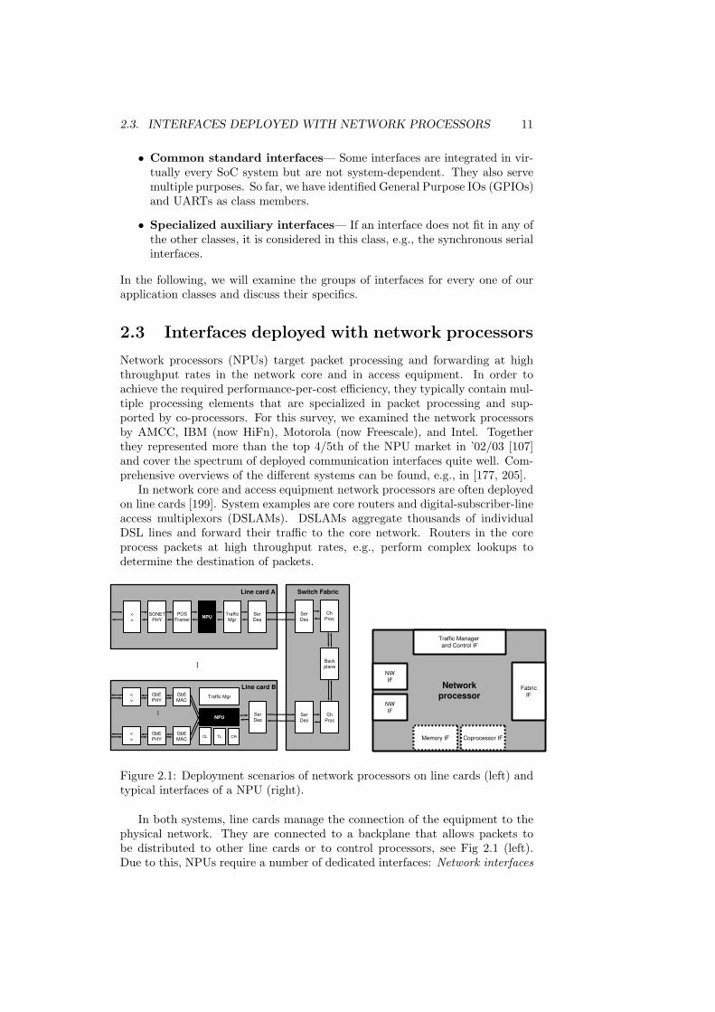
Figure 2.1: Deployment scenarios of network processors on line cards (left) andtypical interfaces of a NPU (right).
In both systems, line cards manage the connection of the equipment to thephysical network. They are connected to a backplane that allows packets tobe distributed to other line cards or to control processors, see Fig 2.1 (left).Due to this, NPUs require a number of dedicated interfaces: Network interfaces

12 CHAPTER 2. REVIEW OF COMMUNICATION INTERFACES
connect the processor to the physical network, a switch fabric interface accessesthe backplane, a control plane interface connects to an external processor thathandles the control plane and also maintains the NPU and its peers on the linecard, memory interfaces handle packets and table lookup data, and co-processorinterfaces are used for classification, quality-of-service, and cryptography accel-erators. While some of these interfaces (e.g. memory and network interfaces)are well covered and documented by mature I/O standards, others, especiallythe switch fabric interface, still lack sufficient standardization.
The interfaces deployed by the examined network processors are listed inTable 2.1, grouped according to our usage classes. The table confirms the factthat network processors deploy a large number of quite diverse interfaces. Thetable also reveals the diversity in memory and network interfaces among theprocessors. In the following these interfaces will be discussed more closely.
Table 2.1: Network processors and their I/O interfaces.
SoC Intel IXP Freescale IBM/HiFn Broadcom AMCCInterface 12/24/2800 C-5 PowerNP BCM 1250 nP3700
Network interfacesNumber of IFs 1 16 CPa+ 1 SWb 4 PMMc+ 2 SWb 3 4IX-Bus (yes) — — — —Utopia yes yes (yes) — —CSIX yes yes yes — —SPI/POS-PHY yes unknown yes — yesMII/GMII/TBI — yes yes yes yesFlexbus — — yes — —
Memory interfacesSRAM 1x /2xQDR 2xZBT 2x QDR/LA-1/ZBT 2x QDRSDRAM 1x /DDR/3xRDRAM SDRAM (PC100) 8x(DDR) DDR 4x DDR
Extension interfacesPCI yes yes yes yes —NPLA-1 — — (yes) — yesHypertransport — — — yes —PowerPC IF — — — — yes
Test and debugJTAG 1x 1x 1x 1x 1x
CommonCore/Type yes/ARM no/— yes/PowerPC 2x/MIPS no/—GPIO 4-8x — 3x yes —UART 1x (MDIO) no 2x (1x)
AuxiliaryMDIO 0/(yes) yes (SPM) — unknownSerial boot ROM 1x 1x (SPM) 2x(SMB) unknown
a one per channel processor b switch interface c physically multiplexed macros for pin-sharing
Network Interfaces. Network processors implement two sets of interfaces toconnect to the physical network: Ethernet and ATM. These interfaces usuallyperform OSI Layer 2 functions: media access control (MAC) in case of Ethernet

2.3. INTERFACES DEPLOYED WITH NETWORK PROCESSORS 13
and segmentation and reassembly (SAR) for ATM. The physical layer (PHYlayer, layer one), which is normally provided externally, is connected via one ofthe following three interfaces:
• The Media Independent Interface [82] (MII) or one of its variants (RMII,SMII) is commonly used for Ethernet and supported virtually by everyNPU. These interfaces come in three performance classes: 10/100 Mb/s(MII), 1 Gb/s (GMII), and 10 Gb/s (XGMII).
• The Utopia interface [6, 7, 8, 9] is used for ATM environments to connectexternal PHY devices. Utopia has four throughput classes: 155Mb/s (L1),622 Mb/s (L2), 3.2Gb/s (L3), and 10Gb/s (L4).
• System-packet interfaces [137] (SPI), which are similar to Utopia, are usedfor ATM and packet-over-SONET (POS) environments to interface to ex-ternal framers. SPI/POS-PHY classes range in their throughput from 622Mb/s to 40 Gb/s (SPI-5).
In order to manage the PHY modules connected to the networking interfaces,an auxiliary PHY management interface (MDIO [82]) is provided. IBMs SPMmodule, for instance, requires an external FPGA for this. This way, the SPMmodule can support different interface types.
In addition to Utopia and SPI network processors that dedicate ports forinterfacing an external switch fabric use one of the following two options:
• The common switch interface [135] (CSIX-L1), a relatively wide interfacethat needs 64 data pins at max. 250 MHz to support 10Gb/s and in-bandflow control.
• The network processor streaming interface [135] (NPSI) based on 16 LVDSdata pins at 311-650 MHz and two to four additional flow control bits.
Proprietary interfaces are becoming more and more obsolete and are succes-sively being replaced by standardized interfaces. Intel, for instance, has decidedto replace the IX bus by SPI/Utopia interfaces in its second generation NPUs.
System extension interfaces. The system extension interfaces of networkprocessors fall into two categories: control plane and co-processor interfaces. Intheory, both types can be use equal IO functionality. The control plane interface,however, is more likely to be generic and well-established. The co-processorinterface, on the other hand, can be optimized for low latency interactions. Inpractice, we find only one standard control plane interface commonly used:
• The peripheral component interface [149] (PCI) provides a local bus inter-face with a peak bandwidth ranging from 1 Gb/s to 4.2 Gb/s dependingon its version. The newer PCI-X and PCI-Express specifications providehigher point-to-point peak bandwidths but are not yet integrated intoproducts.
Some network processors such as AMCC’s, integrate proprietary interfaces toconnect to peer and control processors. These interfaces may be replaced inthe future as more standardized alternatives to PCI (e.g. RapidIO [160] andHypertransport [76]) become available.

14 CHAPTER 2. REVIEW OF COMMUNICATION INTERFACES
Besides proprietary or network interfaces (SPI), co-processors are often usedmemory-mapped and connected via modified memory interfaces. For this rea-son, the Network Processor Forum specified the NPLA-1 [135] interface:
• The look aside interface is modeled based on a synchronous DDR SRAMinterface and provides a bandwidth of 6.4 Gbit/s per direction at 2x 18bit x 200 Mhz.
Memory interfaces. Although NPUs often integrate considerable on-chipmemories, they in addition need at least two different kinds of external mem-ories: large packet memory and fast memory for auxiliary data. Our NPU ex-amples deploy the most recent memory interfaces, often in multiple instances,to meet their memory bandwidth requirements:
• Double data rate [90] (DDR) SDRAM supports data transfers on bothedges of each clock cycle, effectively doubling the data throughput of thememory device. The ones used in our examples provide between 17 and19.2 Gb/s @ 64 bit x {133, 150} MHz.
• Rambus’ pipelined DRAM (RDRAM) [159] uses a 16 bit-wide memorybus. Command and data are transferred in multiple cycles across the bus(packet-based protocol). Components are available ranging from 800MHzto 1.2GHz, providing 12.8 Gb/s - 19.2 Gb/s peak memory bandwidth.
• Zero Bus Turnaround (ZBT) SRAM [183] do not need turnaround buscycles when switching between read and write cycles. This is beneficialin applications with many random, interleaved read and write operationssuch as accessing routing and lookup tables. Motorola’s NPU, e.g., deploysa 8.5 Gb/s at 64 bit x 133MHz interface.
• The Quad Datarate (QDR) SRAM [158] uses two separate memory portsfor read and write accesses that operate independently with DDR tech-nology, thus effectively doubling the memory bandwidth and avoiding busturnaround. The IXP 2800 implements a total of 4x 12.8 Gb/s at 18 bitx 200 MHz on memory bandwidth based on QDR.
These memory interfaces are standard interfaces. However, memory con-trollers embedded in NPUs are more specialized compared with their generalpurpose counterparts. They need to at least support multiple processing ele-ments, which may access a memory concurrently, e.g. by providing individualcommand queues. In addition, application-specific knowledge is exploited totailor controllers to the specific usage. In Freescale’s example, the queue man-agement, buffer management, and table lookup units are specialized to theirspecific data structures and access functions.
Other interfaces. NPUs that implement a standard control processor on-chipalso implement most of the common GPIO and UART interfaces.
2.4 Residential gateways &Integrated access devices
Residential gateways (RGs) connect the external broadband network to the in-ternal home or small office network. They perform network-related services

2.4. RESIDENTIAL GATEWAYS & INTEGRATED ACCESS DEVICES 15
such as line termination, protocol and address translation, firewall security, andin-home routing. Increasingly, they are also becoming the in-house focal pointfor applications such as home automation and control, audio and video stream-ing, and file/printer sharing. Therefore, they have to deal with a plethora ofdifferent network protocols and communication interfaces. Due to the moder-ate throughput requirements, however, their system architectures are typicallybased on a limited number of embedded standard processor cores, which, insome cases, can be combined with accelerators.
…
Local Loop Local Loop
InterfacesInterfaces
802.11802.11
Data
Mem
Data
Mem HomeRFHomeRF
Power
line
Power
line
PCI/ePCI/e USBUSB
EthernetEthernet
POTSPOTS
IEEE
1394
IEEE
1394
ProcProc
Flash/
ROM
Flash/
ROM
MEM
I/O
MEM
I/O
xDSLxDSL
EthernetEthernet
…
Acc
PeripheralPeripheral
NetworkNetworkSystemSystem
NetworkNetwork
Sub
syst
em
Interface Core Accelerator Memory
CableCable
Home NetworkHome Network
InterfacesInterfaces
Blue
tooth
Blue
tooth
Residential GatewayResidential Gateway
Local Peripheral InterfacesLocal Peripheral InterfacesArchitecturalArchitectural
InterfacesInterfaces
Figure 2.2: Extended RG scenario with exemplary interfaces.
In Figure 2.2, an exemplary RG is shown with its three system-level inter-faces (local loop, home network, and local peripherals) and the architecturalinterfaces. The local loop interface connects to the service provider’s externalbroadband connection (e.g. xDSL or cable). The home network interfaces pro-vide a choice of wired (e.g. Ethernet, HomeRF, or power line), wireless (e.g.802.11a/b/g) network protocols as well as plain old telephony service (POTS).Local peripheral interfaces, e.g. USB, IEE1394, and Bluetooth, allow for con-necting directly to I/O devices without a personal computer such as to cameras,scanners, and printers. Architectural interfaces comprise memory interface(s)and system extension interfaces, e.g. PCI and PCMCIA. Wireless access points,for example, are an instance of the RG shown in Figure 2.2. They bridge wire-less LAN and Ethernet networks and provide, e.g., a PCI/PCI Express interfacefor interfacing to companion chips.
Integrated access devices (IADs) are similar to RGs in their base architecturebut incorporate only a limited number of network interfaces. Instead, theydeploy functions for user interaction. Both systems integrate the same setsof memory interface(s) and system extension interfaces. In fact, IADs andRGs members are often of the same product families, which have the processorsubsystem in common and vary only the set of integrated peripherals.
For the survey, we examined Systems-on-Chip by AMD, Intel, Samsung,Broadcom, Motorola, and Philips. Their deployed interfaces are summarized inTable 2.2, grouped according to our usage classes, and discussed in more detail

16 CHAPTER 2. REVIEW OF COMMUNICATION INTERFACES
in the following sections.
Table 2.2: Interfaces of residential gateways and integrated access devices.
SoC Samsung Motorola Broadcom AMD Philips IntelPeripheral S3C2510 PowerQUICC BCM47xx Au1x00 Nexperia IXP42x
RG RG/NE RG IAD/RG IAD/STB RG/NE
Wired network interfacesUtopia 1x 0-2xFCC — — — 0-2xFE/GbE MAC 2x/- 0-3xFCC/2x 1-4x/- 1-2x/- — 1-2x/—HSS/TDM —/— 2x/8x(SSC) —/— —/— —/— 0-2x/—HPNA — — 0/1x — — —DSL/Phone — — 0/1x — — —
Local peripheral interfacesUSB 1.1 host/ports 1x ? 1x 1/? 1x —USB 1.1 function 1+4 0/1 1x 1x 1xIrDA SIR/FIR (SSC)/- 1/- -/0-1 (GPIO) —IEEE 1394 1x
User interfacesLCD IF — — — 0/1 — —I2S/AC97, link — — — 0-1/1 3x —SPDIF — — — — 1x —
Memory interfacesSmart Card — — — — 2x —SDCARD/MMC — — — 0/2 — —NAND/Fl/CF yes m (yes) — (EBI) —SRAM 1x m — 1x —SDRAM 1x (DDR)m 1x 1x 1x 1x
Expansion interfacesPCI/PCMCIA/Cardbus 1x PCI/PCI-X 1x 1-2 PCI PCIOther external Bus IF — 60x/LocalB 1x/? — 1x/? 1xi
RapidI/O — 0/1 — — — —
Test and debugJTAG 1x 1x 1x 1x 2x 1x
CommonGPIOS 64x 53-120/PIO yes 32-48x yes 16xUART 3x (SSC) 2x 2-4 3x 2xl
AuxiliaryI2C yes yes — — 2x —SSI — — — 0/2 SSI 1x —SPI — yes — 0/2(SSI)n —
i multiple standards l 2x64B FIFOs m 1x EPROM/FLASH/EDO/SRAM/SDRAM via ex-ternal bus unit interfaces. n subset of SPI NE - Network Edge, STB - Set Top Box
Network interfaces. Almost all examples deploy at least one Ethernet MACwith MII interface (cf. p. 13). Systems that implement switching functionalityprovide multiple Ethernet interfaces. Often, Utopia Level 2 and 3 interfaces (cf.p. 13), including SAR, are implemented that, e.g., connect to external DigitalSubscriber Line (DSL) PHYs. In addition, physical layer interfaces to connectto telecommunication WAN environments are found.

2.4. RESIDENTIAL GATEWAYS & INTEGRATED ACCESS DEVICES 17
• The High-speed Serial Interface (HSS) is a PHY interface for primaryrate ISDN (E3/T3 WAN, 45Mb/s) or OC-1/SDH (52Mb/s) point-to-pointlinks. Additionally, it can provide connectivity between LANs such asToken Ring and Ethernet. Multiple interfaces may be supported by usingtime division multiplex (TDM).
The only home network interfaces integrated by the examples are Ethernet andHPNA. Other protocols such as Bluetooth or wireless LAN are provided usingexternal PHY chips and connected by system expansion interfaces.
• The Home Phoneline Network Alliance (HPNA) [73] interface is logicallybased on Ethernet. It basically provides a different PHY layer that inVersion 2.0 provides 10Mb/s via telephone lines. Version 3.0 adds Quality-of-Service at 128Mb/s. With optional extensions, this version can deliverup to 240Mb/s. Version 3.1 enables transfer rates of up to 320Mb/s andadds multi-spectrum operations for network coexistence.
Some vendors integrate network PHYs on-chip. This PHY integration savessystem costs for the most likely deployment scenarios. We found the followingPHYs integrated: 1) 10/100 Ethernet (BCM6345), 2) HPNA 2.0 (BCM4710),and 3) ADSL transceiver and analog front end (BCM6345).
Local peripheral interfaces. There are three deployed local peripheral inter-faces: USB, Infrared and Firewire. All three protocol stacks implement higherprotocol layers that allow for their integration in a home or office IP/LAN net-work:
• Universal Serial Bus (USB) [200] interfaces enable serial data transfersfrom 12Mb/s (v1.1) to 480 Mb/s (v2.0). A USB 1.1 function, whichallows the system to respond to an external master, seems common amongour examples. RGs often implement an additional host function. Thisway, the RG can work stand-alone and access external peripherals activelywithout the help of a PC and can also serve as an intelligent bridge betweenperipherals. Similar to the physical layer of network interfaces, we alsofound some systems that implement the USB PHY layer on-chip.
• Infrared interfaces by the Infrared Data Association (IrDA) [85] are alsoimplemented throughout, although in different versions. RGs and networkedge systems often integrate the low end serial infrared version (SIR) only,which uses an UART and provides speeds of up to 115kb/s. The higherspeed versions MIR (1.5 Mb/s) and FIR (4.0 Mb/s) are more likely to bedeployed by IAD architectures. The new VFIR (12Mb/s) version does notyet seem deployed.
• The Firewire/IEEE1394 interface [4, 81] is deployed only by Philips’ Vipersystem. This protocol seems to be used particularly in combination withimage and audio data streams due to its relatively high bandwidth of upto 400 Mb/s (1394a) or 800 MB/s (1394b).
User interfaces. AMD’s Au1100 and Philips Viper devices are the only devicesthat implement a standard LCD interface, video function, and audio codec con-troller. There are no other dedicated peripherals for user interaction. Instead,user I/O devices are connected via multi-function interfaces such as UARTs or

18 CHAPTER 2. REVIEW OF COMMUNICATION INTERFACES
GPIO if necessary. Even a I2S [152] interface, a 3-wire interface dedicated totransport audio data, requires such a general purpose channel to transfer controlto the external audio devices.
Memory interfaces. All devices provide interfaces and controllers for stan-dard SDRAM. Intel, Broadcom, Philips, and Samsung implement a dedicatedinterface for this purpose. Motorola even implements controllers for each of itstwo external buses. Some systems provide a second controller for static mem-ory devices. AMD’s controller, for instance, supports SRAM, Flash, ROM, pagemode ROM, PCMCIA/Compact Flash devices, and an external LCD controllervia its memory interface. Others use system extension buses instead of individ-ual interfaces. In addition, secure digital card interfaces have been implementedby AMD.
System extension interfaces. IADs and RGs overlap memory and system in-terface functions to some extent. Both interfaces seem interchangeable. In somecases, external peripherals, e.g. an LCD controller, are connected to the memoryinterface, and in other cases, memory devices, e.g. flash memory, are accessed viaexternal bus interfaces. All systems implement either PCI or PCMCIA/Cardbusinterfaces. Motorola implements PCI-X and RapidI/O in its PowerQUICC IIIsystem. These interfaces are used, for instance, to connect to external wirelessLAN modules.
Common interfaces. Multiple UARTs and a large number of general purposeI/O are implemented by the examples. They are used to provide additionalinterfaces, e.g., the chip select in case of Motorola’s memory controller, or forsideband interfaces for external PHYs.
Other interfaces. There is a fair number of different serial interfaces (I2C,SPI, and SII) for moderate communication bandwidth. These interfaces aregeneral purpose and are used for connecting to external system components,mostly on a board-level.
2.5 Wireless application processors
Wireless application processors (WAPs) handle the application part of cellularphones and hand-held devices. Apart from the radio baseband processing, thispart often comprises other functions, e.g. audio/video, security, and storage.Wireless application processors can be seen as IADs with an (external) wirelessnetwork interface. Since they are used in portables, much more emphasis is puton energy efficient architectures than seen before in Section 2.4.
In the following product families by TI, ST, and NeoMagic are being exam-ined. The systems commonly contain at least one ARM9 core and additionalprogrammable accelerators. In addition, TI integrates a DSPs for GSM support.Table 2.3 summarizes the deployed interfaces grouped by our usage classes.
Network interfaces. Wireless application processors do not integrate specificnetwork interfaces. Only TI’s OMAP mentions a wireless LAN interface. It is,however, a standard port that is capable of handling the 54 Mb/s bitstream (cf.TNETW1130 [193]). Similarly, other wireless chips, e.g. baseband processorand Bluetooth PHY, are connected via standard interfaces such as UARTs ormulti-channel serial interfaces.

2.5. WIRELESS APPLICATION PROCESSORS 19
Table 2.3: Interfaces of wireless application processors.
SoC NeoMagic TI STPeripheral MiMagic6 OMAP Nomadik
PDA/AP AP AP
Wireless network interfaceswireless LAN a/b/g — (1x) —
Local bus interfacesUSB host/ports — 1x/3 1xUSB function 1x 1x ?IrDA SIR/FIR 1x/1x 1x/1x ?/1x
User interfacesCamera IF 1x+acc. 1xi 1x+acc.LCD IF 1x+acc. 1xi 1x+acc.I2S/AC97, link 1x/1x 0-1x/1x MSP/MSPj
Keypad — 1x —
Memory interfacesSmart Card/SIM card — 0-1x —SDCARD/MMC 2x 1-2x/SPI 1xNAND/Flash/CF 1x 1x 1xSDRAM/DRAM 1x 1x/DDR 1x/DDR
Expansion interfacesPCMCIA (1x) — —
Test and debugJTAG ? 1x 1xEMT9 ?? 1x ??
CommonGPIOS yes 14x 76xUART 3x 2-3x 2x
AuxiliaryI2C 1x 1x 2x/u-wire — 1x —SPI 2x 2x MSPj
Pulse-Width-Light — 1x —Pulse-Width-Tone — 1x —HDQ/1Wire (Batt) — 1x —LED Pulse Gen. — 2x —
i multiple standards, but no details provided j SPI, I2S, AC97

20 CHAPTER 2. REVIEW OF COMMUNICATION INTERFACES
Local peripheral interfaces. Like IADs, application processors deploy twolocal interfaces: USB and Infrared. In case of USB, both, function and hostinterface, are commonly implemented based on FIR (4 Mb/s). The new VFIR(12Mb/s) version seems not yet have been deployed in the wireless domain.
User interfaces. Specialized LCD and camera interfaces are implemented byall processors. Often, they are associated with accelerators for better perfor-mance/power trade-offs. AC97 and I2S interfaces are provided by virtually allexamples. In some cases, multi-channel serial peripherals are used, which alsosupport other kinds of serial interfaces. TI’s keypad interface seems a propri-etary solution.
Memory interfaces. All processors implement a DRAM memory port. STand TI use DDR technology for lower power consumption. In TI’s case, theinterface is used for flash, compact flash, and NAND flash memories as well,whereas other vendors implement a static memory controller for this purpose. Asecond common peripheral is the secure digital card/multimedia card interface.
Furthermore, TI lists a special SIM card interface. Such SIM cards (or smartcards) are used in GSM phones to identify user accounts and to provide datastorage. They also contain processors that execute programs and communicateover a low speed three wire serial interface.
System extension interfaces. In general, WAPs do not integrate systemextension interfaces but use other types for similar purposes such as variousserial and auxiliary interfaces to link to baseband part, audio codecs, and wire-less PHYs. As an alternative for higher bandwidth, the memory interface isused. The only PCMCIA port among our examples, for instance, is providedby Neomagic’s static memory interface.
Common interfaces. The systems implement a similar number of UARTs inall examples, but quite a different number of general purpose I/O. The smallnumber of only 14 GPIOs in TIs case, is certainly compensated by the largernumber of small auxiliary interfaces.
Other interfaces. Serial interfaces such as I2C and SPI are implemented in allprocessors. TI and ST implement them partly in multi-channel serial peripheralsthat support multiple serial standards. TI’s SD card interface can be used asSPI port, too. TI also implements a number of small auxiliary serial interfacesfor display lights, battery status, and sound/speaker control.
2.6 Discussion and selection of interfaces
In the previous sections we surveyed a number of domain-specific system-on-chipand summarized their use of IO interfaces. In this section, we are compiling thedata on the deployment, discussing trends towards flexibility and selecting anessential set for the subsequent analysis of this dissertation.
Deployed interfaces per die
Depending on the application domain, our systems implement between 8 and 25different interfaces on a single die. Among the three domains, network proces-sors integrate the least number of interfaces with an average of 10, followed by

2.6. DISCUSSION AND SELECTION OF INTERFACES 21
residential gateways with 12 in average; application processors with an averageof 18 use the most communication interfaces, as shown in Table 2.4.
Table 2.4: Number of different interfaces per SoC and domain.
Domain Network Residential Gateways Wireless AcrossProcessors Internet Attached Dev. Processors domains
per SoC 9, 8, 10, 8, 11 13, 10, 10, 13, 10, 15 14, 25, 14 8 - 25Average 10 12 18 12
Table 2.5 shows the set of essential interfaces derived from the domain-specific lists of deployed interfaces. The criteria used for deciding whether aninterface is representative and should be included in the essential set is its com-mon implementation into one domain or the availability of standards. Suchinterfaces are normally well documented and their specification is publicly avail-able. Basically, the final set is the superset of the domain-specific lists and hasapproximately three dozen members. Due to their disjoint function and the lackof standardization are display and camera interfaces excluded. Although not in-tegrated in the examples, PCI Express has been included due to its foreseeabledeployment in next generation devices. We have also included the wireless LAN(IEEE 802.11) family of standards due to their increasing relevance for homeand hand held devices.
Table 2.5: Essential set of deployed communication interfaces.
Interface Deployed standard interfacesclass
Network Utopia, SPI, Ethernet (MII), HSS, TDMwireless LAN
Local peripheral USB, IrDA, IEEE1394User AC97, link, I2SMemory SDRAM, DDR, RDRAM, SRAM, QDR, ZBT,
NAND, Flash, CF, SDCARD, MMC, SmartCardSystem extension PCI, PCMCIA, Cardbus
PCI Express, Hypertransport, RapidIOTest and debug JTAGCommon GPIO, UARTOther MDIO, I2C, SPI, SSI
From the set of 35+ essential communication interfaces, our systems-on-chip integrate between 10 and 20 diverse IO functions of varying performancerequirements. Their heterogeneity has lead to several different implementationtechniques for IO interfaces.

22 CHAPTER 2. REVIEW OF COMMUNICATION INTERFACES
Implementation techniques for communication interfaces
The examination of interfaces in the preceding subsections revealed a tendencytoward the support of different communication standards. This is especiallytrue for the network interfaces of network processors; they are configurablefor multiple standards. Other interfaces such as serial interfaces or memorycontrollers can be configured and parameterized as well. We have observedthree approaches towards flexibility that differ in their degree of configurabilityfrom the hardwired solutions mentioned first.
• Individual IP – Every interface is implemented individually and connectedto dedicated pins. Although this is the common case, it leads to a largernumber of heterogeneous blocks in the system and to high area consump-tion. Memory interfaces, for instance, are usually customized for a partic-ular RAM technology.
• Multiple Macros/pin sharing – The simplest technique to provide flexi-bility is the implementation of multiple macros, which can be used alter-natively in a multiplexed fashion. This way, the macros can share theexpensive pins. Obvious drawbacks of such a solution, however, are theheterogeneity and the area consumption.
– The physically multiplexed modules of IBM’s PowerNP integrate fourdifferent network interfaces.
– Concurrent implementations of USB host and function macros canbe found (e.g. in Samsung’s residential gateway S3C2510 system).However, they do not necessarily share pins.
– Freescale’s PowerQUICC contains a memory controller with threedifferent modules: a high performance SDRAM interface module, amore power-efficient lower performance module (e.g. without burstmode), and three parameterizable modules.
• Parameterizable Interfaces – Virtually all peripherals can be adjusted tosome extent by specifying a well-defined set of parameters. The degree towhich a peripheral is parameterizable (the set and range of parameters)varies with the interface. Here are several examples:
– UARTs – Serial interfaces can be configured, for instance, for differenttransmission speeds and the use of hardware support for protocols(e.g. Xon/Xoff).
– Memory Controller – Timing parameters and organization of the ex-ternal memory modules can be set up at boot time.
– PCI Interface – Some PCI interfaces support multiple versions thatdiffer in bus frequency and width.
– IBM’s Physical MAC Multiplexer (PMM) – The selection signal formultiple (fixed) macros is also a parameter.
Since such parameters are configured (i.e. programmed) by the processorcore and the number of parameters may be substantial, these interfacesare sometimes wrongly considered to be programmable.

2.6. DISCUSSION AND SELECTION OF INTERFACES 23
• Programmable Interfaces – In some interfaces, parts of the functions arecarried out by specialized co-processing elements that are micro-programmable.The capabilities of these elements as well as their association to particularinterfaces vary:
– Freescale’s Serial Data Processors (SDPs) – For a limited set of pro-tocols (Ethernet and ATM) the SDP engines handle individual lowlevel tasks such as bit field extraction and CRC calculation. Each ofthe 16 network interfaces included by the C-5 uses two SDPs.
– Intel’s Network Processing Engines (NPE) – The IXP 4xx systemsimplement these programmable accelerators to support individualnetwork interfaces. The engines are specialized to the needs of aparticular interface but are derived from the same core architecture.This helps to offload computation-intensive tasks from the CPU.
– Freescale’s Communication Processor Module (CPM) – The CPMcontains a processor core that is shared by multiple interfaces andonly executes higher-layer communication protocol layer tasks effec-tively separating these tasks from the main processing system.
In addition to these approaches, orthogonal reuse techniques are found,which can be combined with any of the approaches above but actually do notrequire any configurability.
• Multiple Channels – Multi-channel interfaces handle multiple (communi-cation) contexts simultaneously. They exploit the fact that some com-munications (e.g. time slots in a time division multiplexed link) do notrequire the full performance of a module. Some of our examples alsosupport multiple protocols:
– TI’s multi-channel serial interfaces (MCSIs) – In TI’s OMAP pro-cessors, configurable MCSIs are used (e.g. in clock frequency, mas-ter/slave mode, frame structures or word lengths). Their bufferedversion (McBSP) allows for continuous data streams for a number ofdifferent communication protocols (T1/E1, AC97, I2S, SPI).
– Freescale’s multi-channel controllers (MCCs) – Each MCC supportsup to 128 independent TDM channels (HDLC, transparent or SS7).
• Use of generic interfaces – An additional approach to increase reuse andflexibility is the use of generic interfaces instead of specialized ones. Weobserve three different applications:
– Wireless application processors use interfaces such as UARTs ratherthan proprietary solutions (e.g. to connect to companion chips (e.g.Bluetooth PHY)).
– Almost every system provides a number of general purpose I/Os thatcan be used under software control for any I/O function at the ex-pense of CPU performance.
– Some systems implement generic interfaces such as the serial man-agement interface in IBM’s network processor that may require ad-ditional external logic to support less common usage scenarios.
24 CHAPTER 2. REVIEW OF COMMUNICATION INTERFACES
Focus and set of interfaces for this thesis
This thesis adopts a depth-first approach to the problem of interface diversity.We are not attempting to address a solution for every communication interfaceof the essential set. Instead, the focus is placed on the emerging class of packet-oriented communication interfaces.
Recent communication standards put much effort in better exploitation ofthe physical channel and service quality addressing the need for high communi-cation bandwidths at low costs, see Figure 1.4 on page 4. This in turn has leadto increasingly complex modules which must rely on packet-oriented commu-nication protocols to ensure reliable transfers. Packet-oriented interfaces coverthe better part of the essential interface set. Virtually all network (Utopia,SPI, Ethernet, wireless LAN), system extension (PCI Express, Hypertransport,RapidIO), and local peripheral interfaces (USB, IrDA, Firewire) belong to thistype. The remaining IO modules either are memory interfaces or require onlylimited performance.
From the class of packet-oriented communication interfaces, we have chosen
PCI Express, Hypertransport, RapidIO, Ethernet, and wireless LAN
as examples to be used in this dissertation. The choice of these particular packetinterfaces was motivated by the communication needs of two multiprocessor SoCproducts: first, a network processor device as part of a DSL line card which usesEthernet ports as network interfaces and requires either RapidIO, PCI Express,or Hypertransport as control plane and switch fabric interfaces, and second, awireless access point, which deploys wireless LAN, additional Ethernet ports,and PCI Express as system extension interface.
We are primarily interested in the higher level interface and protocol aspectsof the IO modules and intend our work to be complementary to the efforts ofthe software-defined radio community or initiatives such as the Unified 10GbpsPhysical-Layer Initiative [134] which all focus on the physical characteristics ofIO protocols.

Chapter 3
Analysis of Packet-orientedCommunication Interfaces
The previous chapter identified packet-oriented communication interfaces as thelargest subset of essential IO standards. But how similar are these interfaces?What are their elementary tasks? In order to answer these questions, thisinterface class will now be analyzed on the functional level.
Following a common structure, the five standards PCI Express, RapidIO,Hypertransport, Wireless LAN, and Ethernet are analyzed. Each interface ismodeled in Click. Click is an established framework for describing packet pro-cessing applications. The models are functionally correct and capture the essen-tials of each interface, hence enabling a detailed and quantitative comparison.
Before concluding this chapter with the similarities and dissimilarities ofpacket-oriented interfaces, related work on the modeling, analyzing, and com-paring of communication protocols is discussed.
3.1 Fundamentals
As the basis for the comparison and analysis in the subsequent sections of thischapter, this section describes the fundamentals of communication interfaces.The first subsection discusses aspects related to the SoC integration. The nexttwo sections then focus on protocol-related concepts and identify elementarytasks that are common in packet-oriented interfaces.
3.1.1 Interface surroundings
Communication interfaces (or IO modules) are building blocks for Systems-on-a-chip. They interact with their SoC environment in two distinct directions:to the outside world via the physical interface and to the SoC core via thetransaction interface. Figure 3.1 shows a communication interface embedded inits environment.
The physical link interface is formed by one or more lanes. For duplexcommunication, a lane consists of two opposite unidirectional point-to-pointconnections. The bandwidth of such links can be scaled by changing the num-ber of lanes (cf. Fig. 1.4). In the case of serial protocols such as RapidIO,
25

26 CHAPTER 3. ANALYSIS OF PACKET INTERFACES
Tx BufferTx Buffer
Rx BufferRx Buffer
Status/Control
Status/Control
Config/Error
Config/Error
I/D MemReceive
Receive
Receive
Receive PE node
Regs
I/D MemTransmit
Transmit
Transmit
Transmit PE node
Regs
�
Control
Processor
Comm. Interface
Processing
Elements
System-on-Chip
boundary
Link
contains N Lanes.
A lane includes
Rx and Tx.
MemoryMemory
on-chip
comm.
network
Figure 3.1: A communication interface and its environment.
PCI Express, and Gigabit Ethernet (1000 BaseT) a lane contains only the fourdifferential data signals. Hypertransport may have an explicit clock signal perlane (synchronous mode) and an additional control signal per link.
The transaction interface allows the SoC cores to control the sending andreceiving of data units, the transactions. The SoC may issue requests or re-spond to incoming requests by returning completion transactions (split trans-action model). For interaction efficiency, the module interface may incorporatebuilding blocks such as masters for the on-chip communication network, DMAengines for accessing the core system’s memories, and local transfer buffers. Dis-tinct address spaces (memory, IO, configuration, and message) may be definedto support different communication semantics in the system.
Each interface provides a configuration space which contains the parametersand status information of the IO module. Access to this space is possible viaconfiguration transactions from both directions. A separate internal interfaceto the SoC core can be provided for lean and direct access.
3.1.2 Functional layers
The function of IO interfaces can be structured in three layers following theOSI/ISO reference model as shown in Figure 3.2. Each layer provides a serviceto the above layer by using the service of the layer below. Peer layers on differentnodes communicate with each other by using their particular protocol aspects,which implies using the services from the layer below. The three layers are:
• Physical layer (PHY) — which transmits data via the physical link byconverting bits into electrical signals.
• Data link layer (DLL) — which manages the direct link between peernodes and reliably transmits pieces of information across this link.
• Transaction layer (TA) — which establishes a communication streambetween a pair of systems and controls the flow of information. Since

3.1. FUNDAMENTALS 27
PHY
Mgmt
PHY
MgmtPHY
Tx
PHY
TxPHY
Rx
PHY
Rx
DLL
Mgmt
DLL
MgmtDLL
Tx
DLL
TxDLL
Rx
DLL
Rx
TA
Mgmt
TA
MgmtTA
Tx
TA
TxTA
Rx
TA
Rx
System-on-chip core interface
Physical interface / Pins
Physical
Layer
Data link
Layer
Transaction
Layer
Figure 3.2: Layered structure of packet-oriented communication interfaces.
switched networks require routing, different variants of the transactionlayer might be used in endpoints and switches.
Data flows through these layers in two independent directions: the transmitpath (Tx), which sends data from the device core to the link, and the receivepath (Rx), which propagates data from the link to the device core. At eachlayer, additional control and status information for the peer layer of the oppositedevice is inserted (Tx side) into the data stream, or data sent by the peerlayer is filtered (Rx side) out of the stream by the layer management block. Atransaction at the transaction layer is represented as a packet. The link layerforwards these transaction packets and generates its own data link layer packetsfor the exchange of state information. The PHY layer first converts all packetsinto a stream of symbols which are then serialized to the final bitstream.
The terminology of the layers follows the PCI-Express specification. Ra-pidIO uses a similar layered structure (logical, transport, and physical). Hy-pertransport, however, does not use layers explicitly but relies on the samefunctions and structural elements. Gigabit Ethernet and wireless LAN func-tionality is usually described using PHY and MAC layers. We have divided theMAC layer in DLL and TA aspects. Section 3.1.3 will describe the function ofeach layer for each protocol in more detail.
3.1.3 Elementary tasks
The function of the different packet-oriented communication interfaces is pro-vided by a set of elementary tasks. This section describes the common set,starting from the physical layer upwards. In order to be considered common atask must be used by at least two of our protocols.
Clock recovery Serial interfaces encode the transmit clock into the bitstream.At the receiver, the clock needs to be recovered from data transitionsin the bitstream using a Phase-Locked Loop. To establish bit lock, thetransmitter sends specialized training sequences at initialization time.
Clock compensation The PHY layer must compensate frequency differencesbetween the received clock and its own transmit clock to avoid clock shifts.

28 CHAPTER 3. ANALYSIS OF PACKET INTERFACES
Lane de-skewing Data on different lanes of a multi-lane link may experiencedifferent delays. This skew needs to be compensated at the receiver.
Serialization/Deserialization The width of the internal data path must beadjusted to the width of the lane. Serial interfaces also need to lock thebitstream to symbol boundaries.
8b/10b coding/decoding Data bytes are encoded into 10 bit symbols to cre-ate the bit transitions necessary for clock recovery.
Scrambling/Descrambling Scrambling removes repetitive patterns in thebitstream. This reduces the EMI noise generation of the link.
Striping/un-striping In multi-lane links, the data is distributed to/gatheredfrom individual lanes byte-wise according to a set of alignment rules.
Framing/Deframing Packets received at the physical layer are framed withstart and end symbols. In addition, PHY layer command sequences (e.g.,link training) may be added.
Carrier Sensing This is used to determine if a shared medium is availableprior to transmission.
Cyclic redundancy check (CRC) The link layer protects data by calcula-tion of a CRC checksum. Different CRC versions may be required depend-ing on data type and protocol version.
Ack/Nack protocol In order to establish a reliable communication link, thereceiver acknowledges the error-free packets by using a sequence number.In the case of transmission errors, the packet is not acknowledged (or anot-acknowledge is returned) and the packet is retransmitted.
Classification The classification according to packet types may be based onmultiple bit fields (e.g., address, format, type) of the header.
Packet assembly/disassembly The transaction layer assembles payload andheader and forms outgoing packets according to the transaction type. Thelink layer may add an additional envelope (e.g., CRC, sequence number).The link layer may generate information packets (e.g., Ack/Nack, flowcontrol) to update the link status of its peer.
Flow control A transaction is only transmitted to the receiver if sufficientbuffer space is available at the receiver. The receiver updates the trans-mitter periodically with the amount of available buffer space.
Address validation Incoming transactions should only be addressed to thedevice or its memory spaces, respectively.
Buffers and scheduling A set of individually flow-controlled buffers is re-quired for all transaction types to prevent head of line blocking. Addi-tional sets for quality-of-service may be used.
Configuration and management space The configuration space stores theidentity of the device which is determined during the initialization phaseand the negotiated link parameter. It also allows access to internal stateand error logs.

3.2. MODELING PACKET-BASED INTERFACES IN CLICK 29
Table 3.1, shown later in Section 3.5, groups the elementary tasks accordingto their appearance on the different layers in RapidIO, Hypertransport, PCI-Express, Gigabit Ethernet, and wireless LAN. The table will reveal quite somesimilarities in occurrence and deployment of these tasks. The functional mod-eling of end-point devices for the individual standards in the following sectionswill capture the specifics of each interface.
3.2 Modeling packet-based interfaces in Click
For detailed analysis the full system function of the interfaces and their sur-roundings are modeled. The comparison of the models provides insights intothe similarities of the different protocols and allows for the characterization ofthe packet-oriented interface application domain.
We implement our models in Click [102], a domain-specific framework fordescribing network applications. Click was chosen for several reasons. Clickmodels are executable, implementation-independent, and capture inherent par-allelism in packet flows and dependencies between elements naturally. Fur-thermore, Click’s abstraction level and the rich and extensible element libraryallowed us to focus on interface specifics. By using Click a functionally correctmodel can be derived quickly. And even more important, typical use cases,traffic conditions, and the ideal protocol behavior can be validated precisely.
Click is open source software, implemented in C++, and runs on Linux plat-forms. This section briefly introduces Click’s main characteristics and describesconcepts for modeling packet interfaces. Further information on Click can befound in [100] and on Click’s web site [194]. The Click interface models will bedescribed in subsequent sections.
3.2.1 Click characteristics
In Click, applications are composed in a domain-specific language from elementsthat can be linked by directed connections. The elements describe common com-putational network operations whereas connections specify the flow of packetsbetween elements. Packets are the only data type that can be communicated;their generic format supports arbitrary communication protocols. All applica-tion state is kept local within elements. Two packet communication patternsare distinguished in Click: push and pull. Push communication is initiated bya source element and models the arrival of packets in the system. Pull commu-nication is initiated by a packet sink and models space that becomes availablein an outbound resource.
Figure 3.3 shows a simple Click example using both a graphical syntax andthe Click language. Packets are inserted into the system by the FromDevice ele-ment (push output [black]). The packets flow to the input port of the Classifierelement. This element forwards a packet to one of its output ports dependingon the result of the internal processing, e.g., filtering header fields. Two out-puts are connected to queues. In Click, queues are explicit elements that havepush inputs and pull outputs (white). Hence, the ToDevice can pull packetsout of the queues at its own rate and remove them from the system. Pullingthe packets happens via the packet Scheduler, which selects a packet from itsinputs depending on its policy.

30 CHAPTER 3. ANALYSIS OF PACKET INTERFACES
FromDevice ToDevice
Discard
ClassifierScheduler
Queue0
Queue1
FromDevice -> cl::Classifier [0] ->
cl [1] ->
cl [2] ->
q0::Queue ->
q1::Queue ->
Discard;
[0] s::Scheduler ->
[1] s;
ToDevice;
Figure 3.3: Click example: graphical and textual representations.
3.2.2 Interface specifics
Click implements software based routers on Linux computers, turning theminto network nodes with considerable packet processing capabilities [20]. Thesoftware uses OS functions and interacts closely with the OS, e.g., to access thephysical network ports and their packet streams. Click runs as a CPU threadinside the Linux kernel. Work is scheduled by maintaining a list of elementsthat start Click processing chains.
To model the full system function of our communication interfaces in Click,a number of issues have to be addressed:
• Simulation mode — For the functional verification of our interfaces weused Click in user mode only. Our models also describe the environment,namely traffic sources, sinks, and physical communication channels anddo not depend on external events.
• Precise timing — Our interfaces handle timeouts and must guarantee re-sponse times. Click cannot guarantee precise timing since it relies oncooperative scheduling. Our models do not depend on the absolute sys-tem time. Thus, timing accuracy can be achieved by using timing intervalsthat are large compared to the packet processing time, i.e. the simulationdoes not achieve real-time.
• Flow of control information — Click supports the annotation of packetswith processing state. In some packet flows, however, state informationgenerated downstream needs to be fed back into an upstream element. Toachieve the proper granularity, we explicitly modeled such dependenciesusing tokens. In push connections a token represents the state changeevent. A pull token indicates reading state access.
• Non-packet data types — Besides transaction and link layer packets, statetokens and symbols are used. Both of them are also represented internallyby Click packets. Elements may convert packets into tokens or symbolsand vice versa.
• New elements — We used existing click elements whenever possible, givenClick’s focus which is for standard packet flow and processing functions onlayer 3, and above. In some cases, our interfaces required special elements,which, for instance, provide the Layer 2 processing that would be coveredby the port hardware of the Linux box.

3.2. MODELING PACKET-BASED INTERFACES IN CLICK 31
3.2.3 Model setup
Figure 3.4 shows the most basic simulation setup of the interface models using adirected point-to-point link. An on-chip source communicates via the transmitpart of an interface to a peer system with its receive part. The peer respondsusing a 2nd directed link (not shown). Packet arrivals and departures triggerthe execution of processing paths. In the model, transmit and receive paths aretimed by the Channel element, which pulls symbols out of the transmitter andpushes them into the receiver at a constant rate.
ChannelTx RxSource Sink
pushpull pullpush
Figure 3.4: Basic simulation setup for interfaces that use point-to-point simplexcommunication.
A statically configured rate is sufficient if the data is transferred in chunksof the same size, i.e. with constant bandwidth. The PCI Express, RapidIO,Hypertransport, full duplex Gigabit Ethernet models in the next section usethis simulation setup for their point-2-point connections.
For such connections the transfer delay is negligible. This is different forcommunication via a shared medium. The fact that the medium is busy forthe time of the transfer is crucial for correctly accessing the medium. Colli-sion detection and avoidance depend on the precise transfer delay, as shown inFigure 3.5. The shared channel receives a packet (P1) at an input port and de-lays its transfer to the output port(s). If another packet (P2) arrives while thefirst one is still in transmission, the packets collide. Since both will be receivedscrambled at their scheduled arrival times, the receiver can detect the collision.Collision avoidance is modeled by the extra pull port of the channel. If busy,transmitters pull busy tokens which they can use to delay their transmission.
Shared
ChannelTx
1Rx
1Source Sink
busy
Tx2
P1busy
P1P2 P2
Collision
busy
Figure 3.5: Simulation setup for shared communication channels (top). Forcorrect handling of Packet collisions (P1, P2) transfer delays must be considered(bottom).
This setup in combination with a statically configured rate can be used byhalf-duplex Ethernet. Wireless LAN transfer rates change dynamically. There-fore, the shared channel must support variable rates on a per packet base.

32 CHAPTER 3. ANALYSIS OF PACKET INTERFACES
3.3 Application models
In this section, the individual models are presented and important communica-tion scenarios are discussed. The models capture the complete data and controlflow for the steady state of an interface device. Initialization, configuration, sta-tus reporting, and other management related aspects are simplified. Since weare not interested in physical properties, we do not model clock recovery, or anysynchronization on the physical layer. We verify our models by simulation usingcommunication patterns that were derived manually from the specifications.
3.3.1 PCI Express model
PCI-Express is a serial, packet-oriented, point-to-point data transfer proto-col [25]. There are two different versions of PCI-Express: Base and AdvancedSwitching. The Base specification [150] preserves the software interface of earlierPCI versions. The Advanced Switching version [1] defines a different transactionlayer than the base version to add features important to the networking domain,such as protocol encapsulation, multicast, and peer-to-peer communication.
Che
ckP
(2)
Discard
ChCRC32
Tim
eout
GenAck/N
ChSeqN
Discard
Channel
Channel
Prio
Sch
ed
Paint(11) Gen
Fra
mer
TriggerPaint(5)
Paint(0) SetCRC16
FC
cou
nter
s
Prio
rityS
ched
Paint(2) SetSeqN SetCRC32
ReplayBuf Trigger(4)
Tim
eout
Tee
Cec
kSeq
N
Pul
lTee
Def
ram
er
Che
ckP
(0)
ChCRC16
Cla
ssify
Discard
GenFlUpd
Fl cntr++
Timeout
GenFlUpd
Fl cntr++
Timeout
GenFlUpd
Fl cntr++
Timeout
Cla
ssify
Tee
State
Transaction LayerTransaction Layer Data Link LayerData Link Layer Physical LayerPhysical Layer
Ph
ysic
al C
han
nel
Ph
ysic
al C
han
nel
Sys
tem
Sys
tem
-- onon -
- Ch
ip C
ore
Ch
ip C
ore
AckNackRx
AckNackTx
TaFlRx
TaFlTx
Add
r_va
lidat
ion
Discard
Scr
ambl
e
8b10
b
Ser
ilize
8b10
b
Scr
ambl
e
Des
erili
ze
Figure 3.6: PCI-Express end-point device interface model.
For the purpose of this analysis, we use the Base specification [150] formodeling the critical path of an end-point device. The Click diagram for our

3.3. APPLICATION MODELS 33
implementation is shown in Figure 3.6. The functionality of the elements wasdescribed in Section 3.1.3 on page 27. Based on the model, six cases (A–F) ofinformation flow through the interface can be identified:
A) Outbound transactions. The SoC core initiates a transaction (e.g., aread request) by transferring data and parameters into the transaction buffer,which is a part of the transmit transaction layer (TaFlTx element in the figure).This buffer implements at least three queues to distinguish between posted,non-posted, and completion transactions, which together represent one virtualchannel. Posted transactions such as memory writes do not require a response;non-posted transactions, e.g. memory reads, require a response; completiontransactions are the response for non-posted transactions. From the buffer,transactions are forwarded to the data link layer, depending on the priorityand the availability of buffer space at the receiver side of the link. When atransaction leaves, flow control counters are updated. The data link layer (Ack-NackTx), adds a sequence number, encapsulates the transaction packet witha CRC, stores a copy in the replay buffer, and forwards it to the PHY layer.At the PHY layer, the packet is framed and converted into a stream of sym-bols. The symbols are, if necessary, distributed onto multiple lanes, encodedand serialized into a bitstream before they are transferred to the channel. Theserialization shown in the figure is not modeled. Therefore, the channel runs atsymbol time resolution (cf. Sec. 3.2.2).
B) Inbound transactions. A stream of encoded symbols enters the receiveside of the PHY layer and is decoded, assuming that clock recovery, compen-sation, lane de-skewing, and de-serialization have already been performed. TheDeframer detects and assembles symbol sequences to PHY layer commands andpackets. Packets are forwarded to the link layer. The link layer classifies in-coming packets into transaction packets, link layer packets, and erroneous pack-ets. Transaction packets that pass the CRC and have a valid sequence numberare forwarded to the transaction layer (AckNackRx). Erroneous packets arediscarded. For each received transaction an acknowledge or not-acknowledgeresponse is scheduled. At the transaction layer, the received transaction (e.g.,a read completion) is stored into the appropriate receive buffer queue and theSoC core is notified. As soon as the transaction is pulled from the queue, thereceive flow control counters can be updated, and the transfer is completed.
C) Outbound acknowledge packets. The link layer generates confirmationpackets to acknowledge/not acknowledge the reception of transaction packets(AckNackRx). To preserve bandwidth, they are issued in scheduled intervalsrather than after every packet. Besides the ack/nack type, a packet containsthe lastest valid sequence number and is CRC protected.D) Inbound acknowledge packets. If the received link layer packet hasa valid CRC and is an ack/nack, its sequence number SN is verified (Ack-NackTx). When a valid acknowledge has been received, all transactions withsequence numbers not larger than SN can be purged from the replay buffer.Otherwise, transactions with larger numbers are retransmitted. If there are toomany retransmissions (more than four) or no ack/nack packet has been received,a link retraining command will be issued to the PHY layer.
E) Outbound flow control packets. After having read a transaction fromthe receive buffer and changed the receive flow control counters, the transmitter
34 CHAPTER 3. ANALYSIS OF PACKET INTERFACES
has to be updated. For this purpose, the link layer issues a flow update packet,which is generated from the counter values provided by the TA layer. In theinitialization state, init packets instead of updates are issued to the transmitter.F) Inbound flow control packets. Inbound flow control packets are for-warded by the receiving link layer to the transaction layer. The TA layerupdates its transmit flow control counters and schedules the next packet fortransmission from the pending transaction buffer.
3.3.2 RapidIO model
RapidIO is a packet-oriented, point-to-point data transfer protocol. Like PCI-Express, RapidIO is a layered architecture [161, 48, 180]: The logical layer (ourtransaction layer) specifies the transaction models of RapidIO, i.e. I/O, messagepassing, and globally shared memory; The transport layer specifies the routingof packets through the network (our transaction layer covers the part whichconcerns end devices: the device identification); The physical layer defines theinterface between two devices (our physical layer) as well as the packet transportand flow control mechanisms (our data link layer).
Since there are only minor differences between PCI-Express and RapidIO interms of tasks and packet flow, we are refraining from presenting the completeimplementation here. Instead, the differences on each layer are listed.
• The transport layer implements a different buffer scheme with four prior-itized transaction queues that are flow-controlled together.
• At the link layer, an explicit acknowledge for each packet is required,whereas PCI Express allows the acknowledge of a packet sequence. Thenot-acknowledge provides the cause for an error, which is used for indi-vidual reactions at the transmitter.
RapidIO appends a 16 bit CRC at the end of packets. In the case oflong packets, an interim CRC value is added after the first 80 bytes of thepacket. The much shorter control packets are protected by a 5bit CRC.PCI Express uses 32 bit CRCs for transaction packets and 16bit CRC forlink layer packets.
• The PHY layer uses slightly different control symbols than PCI Express.
3.3.3 Hypertransport model
Hypertransport is a parallel, packet-oriented, point-to-point data transfer pro-tocol for chip-to-chip links [198, 79]. Version 1.1 of the standard [77] extendsthe protocol with communication system-specific features such as link-level er-ror recovery, message passing semantics, and direct peer-to-peer transfer. Inour work, we primarily used the version 1.04 described in [198].
Unlike RapidIO and PCI-Express, the packet transfer portion of a link com-prises groups of parallel, uni-directional data signals with explicit clocks andan additional sideband signal to separate control from data packets. Controlpackets are used to exchange information, including the request and responsetransactions, between the two communicating nodes. Data packets that justcarry the raw payload are always associated with a leading control packet. To

3.3. APPLICATION MODELS 35
improve the information exchange, the transmitter can insert certain indepen-dent control packets into a long data transfer.
Channel
Channel
Transaction LayerTransaction Layer Data Link LayerData Link Layer Physical LayerPhysical Layer
Ph
ysic
al C
han
nel
Ph
ysic
al C
han
nel
Sys
tem
Sys
tem
-- onon -
- Ch
ip C
ore
Ch
ip C
ore Prio
Sch
ed
CR
C32
inse
rt
Ser
ializ
e
FC
cou
nter
s
Prio
rityS
ched
TaFlTx
Paint:
1 – Commands,
0 – Data
Paint(1)
Paint(1)Gen
Tim
edF
lGen
FlowMngr
Fl cntr++
Fl cntr++
Fl cntr++
Add
r_va
lidat
ion
Discard
Cla
ssify
Cla
ssify
DiscardC
heck
P(0
)
Pack_Data
ChCRC32
DeS
eria
lize
TaRx
TaRx
TaRx Data
Command
has data
Posted
Non-posted
Response
Figure 3.7: Hypertransport end-point device interface model.
The base functionality of the Hypertransport protocol is comparable to PCI-Express and RapidIO. However, Table 3.1 on page 48 reveals two main differ-ences: 1) At the PHY layer, Hypertransport does not require framing, channelcoding, clock recovery due to the synchronous interface1, and 2) in non-retrymode2, there is no acknowledge/not-acknowledge protocol at the link layer, anda periodic CRC inserted every 512 transferred bytes is used.
The Click implementation of an interface for a single-link end device is shownin Figure 3.7. For the model, we partition the Hypertransport protocol logicallyamong our protocol layers as defined in Section 3.1.2, although layers are notused by the specification. Due to the absence of an ack/nack protocol, only fourpaths through the interface are important:
A) Outbound transactions. Similar to PCI-Express, a transaction is writ-ten into one of the transaction buffer queues (posted, non-posted, response).Transactions are forwarded depending on the priority and the availability ofreceiver space (flow control). When a transaction leaves, flow control counters
1Rev. 3.0a [79] adds an asynchronous mode (Gen3) using scrambling and 8b/10b coding.2In retry mode [77] the link layer uses per-packet CRCs and an Ack/Nack protocol.

36 CHAPTER 3. ANALYSIS OF PACKET INTERFACES
are updated. The link layer performs the periodic CRC. The CRC value is in-serted into the packet stream every 512 bytes. If necessary, the data link layerwould interleave the current outgoing transaction with control packets, e.g. forflow control. If there are neither waiting transactions nor control packets, idlecontrol packets are issued to the PHY layer. At the PHY layer, the packet isserialized and distributed according to the link width.B) Inbound transactions. The PHY layer de-serializes the stream of incom-ing data into 4 byte fragments, colors them as control or data, and sends themto the link layer. At the link layer, the CRC check is performed and the frag-ments are assembled to packets. After a classification step, transaction packetsare passed on to the next layer. At the TA layer the address check is performedthat discards invalid transactions. Valid transactions are stored in the appro-priate receive buffer queue, and the network processor core is notified. Whenthe transaction is pulled from the queue, the receive flow control counters areupdated and the transfer is completed.
E) Outbound flow control packets. The link layer issues NOP packetsthat include flow control information provided by the transaction layer. InHypertransport, only the counter differences (max. 2bit per flow counter) aretransferred. During initialization, multiple packets are therefore necessary totransfer the absolute value of the receive buffer.F) Inbound flow control packets. Inbound flow control information is for-warded by the receiving link layer to the transaction layer. The transactionlayer updates its transmit flow control counters and schedules the next packetfor transmission from the pending transaction buffer.
3.3.4 Gigabit Ethernet model
Gigabit Ethernet (IEEE 802.3) [83] is a serial packet-oriented data transferprotocol for local area networks. Increasingly, it can be found as backplane incommunication systems [174]. The IEEE 802.3ap task force currently discussesthe standardization. Traditionally, Ethernet has been used in half-duplex modewith a shared medium and collision detection. Like the preceding protocols itcan be used in switched point-to-point settings in full-duplex mode as well.
The Click implementation of a Gigabit Ethernet controller is shown in Fig-ure 3.8. The function is partitioned logically among our protocol layers asdefined in Section 3.1.2. Our TA and DLL layers split the function of the Eth-ernet standard’s MAC layer. The PHY layer classification is identical to thestandard. The 1000Base-X PHY shown in the figure requires 8b/10b codingsimilar to PCI Express and RapidIO.
In Figure 3.8, the black portion of the graph is used in full-duplex mode. Theadditional red processing paths (its elements are marked by a *) are required forhalf duplex. Both modes must be supported since the mode can be negotiateddynamically. There is no flow control in half-duplex mode; in duplex mode theframer supports burst transfers, collision handling, and retransmissions.
Due to the absence of an ack/nack protocol, only four paths through theinterface are important:
A) Outbound transactions. The SoC core stores outgoing frames in theinput queue. As soon as the link is idle, the frame is read and stored in theframer while an FCS is added. The framer adds pre- and postfixes (SOP, EOP,

3.3. APPLICATION MODELS 37
Data Link LayerData Link Layer Physical LayerPhysical Layer
Ph
ysic
al C
han
nel
Ph
ysic
al C
han
nel
Sys
tem
Sys
tem
-- onon -
- Ch
ip C
ore
Ch
ip C
ore
Transaction LayerTransaction Layer
GbE
Def
ram
er
GbE
-8b1
0b
Ser
ilize
Des
erili
ze
PAUSE
(Flow Control)
PA
US
E
CO
NT
RO
L
Rx
PA
US
E
CO
NT
RO
L
Tx
Tee
Tee
Autoneg
NotifyQueue
GbE
Fra
mer
Pai
ntF
ilter
(0xf
f)
Set
CR
C32
Pai
nt(3
)
Prio
Sch
ed
Cnt
rlDel
ay
Eth
erE
ncap
Prio
Sch
ed
Pai
nt(1
)
Pai
nt(0
xff)
GbE
-8b1
0b
Che
ckP
aint
(1)
Che
ckP
aint
(3)
DiscardChe
ckC
RC
32
Cla
ssifi
y
Hos
tEth
erF
ilter
Discard
Rat
edU
nque
Col
lisio
nDet
ect
0
0
Sha
redC
henn
el
Channel
Channel
busyCarrier Sense
*
*
*
*
Figure 3.8: Gigabit Ethernet MAC and PHY (1000Base-X) model.
extension symbols) and breaks the packet into a stream of symbols that aresent over the link. After the packet, the framer generates a sequence of idlesymbols to ensure the required inter-frame gap of 12 bytes. In case of a collision(half-duplex, collision detect), the framer interrupts the current packet transfer,sends JAM symbols, backs off, and retransmits the stored packet (or discard itif retransmitted too often).B) Inbound transactions. Inbound streams of symbols are received, decoded,and assembled to frames at the PHY layer. At the DLL layer, the frames areclassified. Configuration frames are sent to the Autoneg element. Frames with-out PHY errors and valid CRC are forwarded to the transaction layer and storedin the output queue (NotifyQueue), given their destination address matches.
E) Outbound flow control packets. When particular full or empty thresh-olds are reached, the output queue notifies the flow control unit (PauseCon-trolTx), which generates PAUSE or CONTINUE frames depending on the typeof message (almost full/empty). These specially typed ethernet frames have ahigher priority than other frames and are transmitted as soon as the link is idle.F) Inbound flow control packets. At the receiver’s transaction layer, theflow control frames are fed into the flow control unit (PAUSE CONTROL RX).This unit extracts the delay value from the payload and sets the timer of theControlledDelay element to delay the transfer of the next transaction frameaccordingly. CONTINUE frames actually cancel the timed delay to improveperformance.

38 CHAPTER 3. ANALYSIS OF PACKET INTERFACES
3.3.5 Wireless LAN model
Wireless LAN (IEEE 802.11) [49, 36] is a packet-oriented protocol that connectsstations to Ethernet networks using radio waves. Stations are usually mobile.A central device, the access point, manages the wireless network and performsthe wired-to-wireless bridging. Communication over the air is quite differentcompared to shared medias in wired networks. Air channels are open to in-terception, highly unreliable, and dynamically change their properties due toeffects such as mobility and multi path interference. The wLAN protocol has tocope with this channel properties at the price of higher protocol complexity. Forthis reason a wireless MAC extends and adds features compared to the protocolsdiscussed before:
• Virtual carrier sensing and collision avoidance — In order to de-termine if the medium is available, virtual carrier sensing is used. 802.11frames carry a duration field, the Network Allocation Vector (NAV), thatis used to reserve the medium for a time period. Stations set the NAVto the time they will be using the medium. Other stations receive thisvalue and set their NAV timers accordingly. A station knows the mediumis busy if its NAV counter is not zero and can delay its own transmission.To avoid collisions caused by hidden nodes stations may use Request-to-send/Clear-to-send (RTS/CTS) control frame handshakes with extendedNAV values prior to the actual data transmission (cf. Fig. 3.10).
• Interframe spacing for priorities and contention resolution —Access to the air is controlled by a set of coordination functions such asthe one for contention-based service (DCF). They use varying interframespaces to provide prioritized access. The higher the priority of the trafficthe shorter the interframe gap. Four spaces are defined: SIFS (shortest)for highest priority transmissions (e.g. ACK, RTS/CTS), PIFS for con-tention free transmissions, DIFS for contention-based transmissions, andEIFS for recovery from erroneous transmissions3. Contention resolutionis achieved by means of a backoff window that follows the DIFS interval.
• Periodic exchange of network state — Wireless networks require theexchange of network state and management information at regular inter-vals, e.g. to identify the network and to announce its capabilities. This isachieved by beacons sent by the access point. Similar to the negotiation ofthe Ethernet link speed, stations can explicitly exchange capability infor-mation such as a list of available transfer rates by sending a ProbeRequest.The access point responds if the parameter sets are compatible. From thenegotiated set of transfer rates, for instance, the transmission rate of apacket may be selected dynamically, depending on feedback on the quali-ties of previous transfers.
• Extra processing functions — Two essential functions, which wouldbe left to higher layers in other protocols, are integrated into wLAN:fragmentation and encryption. Fragmentation of transaction packets andmanagement frames into a burst of small chunks increases reliability. En-cryption methods defined at the MAC layer enable secure authentication,
311n uses another access time, RIFS, which is shorter than SIFS and is used in burst mode

3.3. APPLICATION MODELS 39
key management, and private communication usually at the expense ofconsiderable computational effort.
For this analysis, the Click model focuses on the MAC layer (our transaction andlink layers) as specified by the 802.11a/b/g standard. The air model receivescomplete frames and their transfer rate and generates the desired transmissiondelay and half-duplex/busy behavior of the MAC/PHY interface.
Figure 3.9 shows the main processing paths of the model. Wireless LANdoes not implement flow control but adds additional control and managementframe processing path for channel reservation and the permanent exchange ofstate:
Data Link LayerData Link Layer
Ph
ysic
al C
han
nel
Ph
ysic
al C
han
nel
Sys
tem
Sys
tem
-- onon -
- Ch
ip C
ore
Ch
ip C
ore
Transaction LayerTransaction Layer
Sha
redC
henn
el
busy
Wep
Enc
ap
DCFrate
selection
scheduled packetQueue
Medium busy
Chain busy
1
2 3
DCF chain busy
2
1
3
ACK/
CTS
0
DCFrate
selection
scheduled packetQueue
Medium busy
Chain busy
1
2 3
DCF chain busy
2
1
3
ACK/
CTS
0
DCFrate
selection
scheduled packetQueue
Medium busy
Chain busy
1
2 3
DCF chain busy
2
1
3
ACK/
CTS
0
DCFrate
selection
scheduled packetQueue
Medium busy
Chain busy
1
2 3
DCF chain busy
2
1
3
ACK/
CTS
Wifi
Fra
gmen
t
Wifi
Seq
Wep
Enc
ap
Wifi
Fra
gmen
t
Wifi
Seq
Wep
Enc
ap
Wifi
Fra
gmen
t
Wifi
Seq
Wep
Enc
ap
Wifi
Fra
gmen
t
Wifi
Seq
Pai
ntS
witc
h
Wifi
Enc
ap
Set
RT
S
Pro
beT
xRat
e
Wiff
iDec
ap
Wiff
iDef
rag
Pai
ntS
witc
hWiff
iDec
ap
Wiff
iDef
rag
Wiff
iDec
ap
Wiff
iDef
rag
Wiff
iDec
ap
Wiff
iDef
rag
Upd
ateN
AV
Che
ckC
RC
32
Carrier Sense
Hos
tEth
erF
ilter
Wep
Dec
ap
Cla
ssifi
er
BC
-Filt
er
Gen
Ack
data
managment
Cla
ssifi
er
Classifier
PrioSchedTee
control
Ack/CtsRTS
unicast data
multicast data
GenCTS
Set
CR
C32
Set
Dur
atio
n
Scanner &
Tracker
ProbeRequester
Paint(3)
�
Beacons & Probe responses
Other Mgmt frames
�
Wifi
Dup
eFilt
er
Wep
Dec
ap
Wifi
Dup
eFilt
er
Wep
Dec
ap
Wifi
Dup
eFilt
er
Wep
Dec
ap
Wifi
Dup
eFilt
er
Figure 3.9: Click model of a wLAN 11n a/b/g station. The model includesservice differentiation as specified by the 11e standard. Not all managementprocessing paths are shown.
A) Outbound transactions. Ethernet framed transactions from the SoC coreexperience several processing steps before they are stored in a QoS queue: theEthernet header is replaced by a wireless header, a sequence number is added,and, if necessary, the frame is fragmented and encrypted. Also, the transfer rateis selected based on the channel feedback for this connection. The DCF module,which handles the timed access to the medium, reads the transaction from thequeue as soon as the link state permits. This means, that the frame is read ifthe medium has been idle for at least DIFS time, no retransmission or framesof higher priority are waiting, and no other station has won the contention. Inthis case, the duration field is set, the FCS is appended, and the frame plus itssideband information are sent to the PHY layer.

40 CHAPTER 3. ANALYSIS OF PACKET INTERFACES
B) Inbound transactions. Inbound wireless frames are received and for-warded to the link layer. The link layer checks the CRC, updates its NAV timerwith the frame’s duration value, discards frames addressed to other stations,and classifies the frames left into data, control, and management frames. Dataframes are forwarded to the transaction layer which separates them by QoSclass, removes duplicates from the stream, decrypts and reassembles if neces-sary, and replaces the wLAN header with an Ethernet header. Then, they arestored in the output queue.
C) Outbound acknowledge. Valid unicast data frames that were accepted bythe DCF element schedule the generation of an acknowledge control frame. Assoon as the SIFS timer expires, the frame is pushed into the regular processingpath for outbound transactions (see path A), i.e. its duration field is set andthe FCS is added before it is sent to the PHY layer. In the model, acknowledgesare always transmitted at the rate the data frame was received.D) Inbound acknowledge. Inbound acknowledges experience the same pro-cessing path as inbound transaction frames (see case B) until they are classifiedand forwarded to the DCF. Here, retry and back-off counters are reset if thelink expected the acknowledge. There is a timeout for not received acks.G) Outbound RTS/CTS. If an outbound transaction frame is larger than athreshold (SetRTS), the generation of an outbound RTS frame is triggered assoon as the frame is read by the DCF element (cf. case A). The generation ofCTS frames is triggered by reception of RTS. Similar to outbound acknowledges,RTS and CTS frames just follow the regular processing path of case A, afterDIFS or SIFS time, respectively.H) Inbound RTS/CTS. Inbound RTS and CTS frames travel the process-ing path F to the DCF. A RTS triggers the generation of the associated CTS(cf. path G). A received CTS frame triggers the transmission of an outboundtransaction after SIFS time.
I) Outbound management frames. Outbound management frames followthe processing path of outbound transaction (path A) except that they do notneed the wireless header encapsulation step. In the model, the generation ofselected frames, e.g., a ProbeRequest, is triggered by the SoC core.J) Inbound management frames. Received management frames travel upto the transaction layer similar to inbound transactions (path B). Here they areclassified and either handled directly or forwarded to the SoC core. Receivedbeacons, for instance, are fed into BeaconScanner/Tracker elements in order tomonitor and update the interface’s network state.
Protocol timing constraints
Different frames and the coordination of shared medium access have to followstrict timing rules. In Figure 3.10, an atomic data frame transfer including anoptional medium reservation sequence is shown. In this example, station STAhas gained access to the air and sends a reservation request (RTS frame) tothe access point (AP). The AP has to reply after a defined time interval (SIFSperiod) with a CTS control frame. After reception of CTS, the STA starts thedata transfer after another SIFS period. At the end, the AP acknowledges thesuccessful reception of the data with an ACK control frame, again after oneSIFS period. This sequence forms an atomic transfer. The short SIFS period

3.4. RELATED WORK 41
prevents other stations from interrupting the transfer. After recognizing the freemedium they must wait considerably longer (DIFS period and random backoff)before they may transmit.
STA
AP
RTS
CTS
Data frame
ACK
SIFS SIFS SIFSDIFS & backoff
time
Figure 3.10: Atomic data frame transfer (IEEE 802.11).
All these strict timing requirements dealing with inter-frame spaces, responsetimes, and transmission opportunities are in the low µs range. As a result, thecycle budget for the required frame processing is tight, as will also be pointedout later in Section 5.1.3.
3.4 Related work
Related work for this chapter can be found in two domains: 1) the comparison ofcommunication protocols and their I/O interfaces, and 2) modeling and analysisof packet processing applications. References to the individual standards werealready provided in Section 3.3.
3.4.1 Comparing protocols
The rising interest in new interconnect standards has been covered by severalarticles that provide overviews on changing sets of standards [16, 38, 46, 78,125, 148, 163, 134, 162, 181].
• [38, 46, 148, 181] are introductional and do not conclude on similarities.
• A thorough survey of I/O adapters and network technologies in generalis presented in [162]. The paper particularly focuses on requirements forserver I/O.
• Selected issues of the physical layers of PEX/ASI, RIO, and 10Gb/s Eth-ernet are discussed by Noel et al. in [134].
• In [163], Reinemo et al. discuss the quality-of-service features of threeprotocols Infiniband, Ethernet, and PEX/ASI. They conclude that eachof the protocols may have its advantages, depending on the use case.
• Although in [16] and partly in [78] some details of HT, PEX, and RIO arecompared, a comprehensive picture has not been drawn of the essentialelements and processing paths of the interfaces.
We are interested in the similarities and dissimilarities of the higher level in-terface and protocol aspects, i.e. the transaction and link layers of our protocols.

42 CHAPTER 3. ANALYSIS OF PACKET INTERFACES
The different physical characteristics of the protocols are already addressed byinitiatives such as the Unified 10Gbps Physical-Layer Initiative (UXPi) [134] andindividual companies such as Rambus, [125]. An early version of our work [169]compared the interfaces for PCI Express, RapidIO, and Hypertransport. Thecurrent version adds Ethernet and wireless LAN to the comparison and extendsthe modeling concepts to shared medias and precise timing.
The article by Bees and Holden [16] comparing Hypertransport, PCI Ex-press, and RapidIO complements our analysis.
3.4.2 Modeling packet processing applications
There is a large body of work that uses network and packet processing modelsfor many purposes such as the analysis of protocols or the evaluation of anapplication’s performance for a given traffic and network setup.
Given the diverse purposes, modeling approaches for packet processing appli-cations fall into two broad categories: analytical methods and simulation basedtechniques. Analytical methods such as network calculus [110] usually abstractthe system function. They are used, e.g. in [195], to reason about selectedproperties of the network system or to conduct static/worst-case performanceanalyses for generalized traffic scenarios. Simulation-based techniques on theother hand rely on characteristic workloads but may capture dynamic systemeffects as well. Depending on the abstraction level, they also capture the actualsystem function.
For the functional comparison of our interfaces, we are focusing on simulation-based approaches since they enable the verification of the models system func-tions. This is one of our six requirements that are listed and discussed next.
Requirements
For the functional comparison, the models must fulfil six requirements:• Interface device focus — We are focusing on the communication proto-
col interface and its surroundings, meaning the protocol endpoint thatsends/receives data, not the communication network itself.
• Full system function — For the functional analysis, our models must cap-ture the flow of data with its processing functions and the flow of controlincluding the state machines of the communication interface, correctly.
• Executable model — An executable model enables verification and vali-dation of the system function, e.g. by simulation or emulation.
• Architecture independent — For the comparison, we are interested in thefunction only. No assumptions whatsoever must be made in the modelabout the platform the system will be running on.
• Component-based model — To expose concurrency and dependencies withina protocol function, the models should be composed from components. Alibrary of elements facilitates reuse among protocols.
• Timed models — Communication interface are reactive systems that needto meet real-time requirements. An explicit and metric notion of time isrequired to model time-outs, deadlines, and rates in the system.

3.4. RELATED WORK 43
These requirements are driven by the goals of the interface analysis. How-ever, we want to reuse the device models as input for the architecture explo-ration. The models should serve as golden units and hopefully provide a pathto the evaluation of an embedded platform as well.
Models of Computation
Models of Computation (MoC) are an established approach to capture the be-havior of concurrent and heterogeneous systems for the specification and designof embedded systems [24, 89]. MoC basically are design patterns that 1) sepa-rate computation, communication, and control, 2) describe the system behavioras interaction of components, 3) guarantee desired system properties, and 4)can be executed.
A number of MoCs are relevant for describing packet processing applicationsand are therefore discussed here:
• Process Models — Components in process models are sequential processesthat run concurrently and communicate via messages either synchronously(CSP – Communicating Sequential Processes [71]) or via FIFO channelswith blocking read (Kahn process networks [93], extended in [141] tobound fifo sizes by using blocking writes). CSPs fit particulary well toresource sharing and client/server applications. In [182] for instance, theyare used to study intrusion detection in a TCP network. Kahn processnetworks are used, e.g. in [191], to model streaming signal processing ap-plications. Stream processing exhibits strong similarities to the flow ofpackets through our communication interfaces. However, process modelsare untimed.
• Petri Nets— Petri nets are directed graphs of nodes connected by edges.Two different types of graph nodes exist: places and transitions. Placesrepresent state. They store tokens. Transitions represent actions of thesystem. The modify state by consuming and producing tokens dependingon enabling and firing rules. Places are always connected to transitionsand vice versa.Petri nets are a graphical formalism to express the concurrency of sys-tems. They are analyzable and can be used to prove certain propertiesof the modeled system. A review of the fundamental concepts is givenin [131]. High-level Petri nets extend the fundamental place/transitionsystems. Coloured Petri nets [91] make tokens distinguishable to enabledata-dependent modeling. Time and timed Petri nets add notions of timeto the system (see references in [131, 91]). The work in [88] adds hierarchyand parameters to enable component-based modeling techniques.Petri nets are powerful enough to model most of the other MoCs such asthe Kahn process networks above [114]. High-level Petri nets have beenapplied successfully to many domains [131], including performance mod-eling and the analysis of communication protocols. They are suited tomodel and simulate our communication devices. However, there expres-siveness is not required for the interface comparison. Also, functionallycorrect models that capture control and dataflow grow complex, quickly.

44 CHAPTER 3. ANALYSIS OF PACKET INTERFACES
• Finite State Machines — Finite state machines (FSMs) model the behav-ior of control-dominated reactive systems by composing events, a finitenumber of states, and actions. A FSM sequentially responds to externalevents with actions. An action may depend on the current state and maygenerate outputs and transitions of the state.Hierarchical finite state machines, as first introduced by the Statechartsmodel by Harel [66], enable the concurrent and hierarchical compositionof FSMs by defining and states (system is in state a and b) and or states(system is in state a or b). This handles the problem of exploding statespaces for larger systems and significantly increases usability. In general,hierarchical finite state machines are an useful abstraction for describingthe control facet of communication protocols. They can be executed, andthere is a clear path to hardware and software implementation. How-ever, they cannot express data flow and processing well. For this reason,FSMs are often combined with other computation models in hybrid mod-els. The *charts study by Girault et al. [52], for instance, discusses thecombination of hierarchical FSMs with, e.g., process networks, to capturethe dataflow and computational facets of applications as well. The Clickmodel of computation encapsulates state and state machines within in-dividual elements. In addition, our packet-flow oriented interface modelsuse state tokens that flow between elements to explicitly achieve FSM-likebehavior.
• Queueing Networks — Queueing networks are composed of systems ofqueues and servers [99]. Queues store transactions until a server becomesavailable. The server creates, processes, or deletes a transaction. Thisconsumes a specific amount of time after which the transaction may beforwarded to the next queue. Service time and route can depend on theclass of a transaction [15]. Queues store transactions according to theirqueuing discipline. With first-in-first-out (FIFO) queues and servers withprocessing function, queuing networks become similar to (timed) Kahnprocess networks.Using queuing networks one can determine, e. g., the residence time oftransactions in the system, the average queue length, and the server uti-lization. In [197, 139], for example, queuing networks are used to model thedistributed coordination function of the IEEE standard. The authors rea-son about delays and queue lengths in the system, using analytical resultsthat were verified by discrete event simulation. Simulation frameworksfor queueing networks include the SimEvents [123] extension of Simulinkand SystemQ [189]. For capturing the system function of our communi-cation protocol interfaces, queueing networks are less suited. The strictqueue/server composition scheme limits the expressiveness of the modeland restricts its granularity.
• Discrete Event — In discrete event models, components communicate viaevents that are associated with a time stamp. All events in the systemcan be ordered following a global time. A component may generate eventswith a future time stamp but can receive only those available at the cur-rent time. Discrete-event is a quite general model of computation andfrequently used in general purpose simulators for applications such as net-work simulation.

3.4. RELATED WORK 45
Today, there exist a number of established network simulators. Promi-nent representatives4 with large user communities include ns-2 [23], Op-Net [138], and OMNeT [201]. Network simulators are usually targetedat a range of protocols. Models are composed hierarchically from libraryelements, often in a special specification language. Typically, the libraryis implemented using a regular programming language such as C++ orJava. The focus of network simulation is on simulating communicatingnodes and observing the dynamic protocol behavior within the network,e.g., the TCP feedback mechanism or the effects of hidden nodes in wire-less networks. Little attention is paid to the details of individual networkdevices. To speed up simulation performance, nodes are significantly ab-stracted. This is illustrated by a study on the effects of detail in wirelessnetwork simulation [69]. The most detailed cases in this study use a blackbox cost model of the MAC layer for analyzing the energy consumptionof the network.
Each MoC has its own strengths and weaknesses. In fact, general purposemodeling and simulation frameworks often combine multiple MoCs for hybridsystem models [156, 143] or provide extensions to support other MoCs on top oftheir built-in one (cf. Simulink’s StateFlow and SimEvent modules). However,they all provide only little support for our communication interfaces, in termsof domain-specific primitives and data types.
System-level modeling languages
System-level modeling languages are aimed at models that address two essen-tial needs [89]: firstly, the need for a specification that captures the system’sfunction and requirements in a precise, unambiguous and analyzable way, espe-cially during the early design phases of a system, and secondly, the need for asystem description that provides a path to an efficient implementation withoutoverconstraining the solution.
According to Edwards et al., the distinction between a language and theunderlying model of computation is important [45]. The authors point out thata model of computation can be supported by different languages. Its MoCeffects the expressiveness of a language. A language can be too expressive sothat many analysis and synthesis problems become practically unsolvable. Alanguage also can be incomplete or abstract. A coordination language as used insome of the network simulators, for instance, only describes the interaction-of-components facet of a model of computation but not the computation containedwithin the components. Instead, it provides an interface to another languagefor the components.
In the context of packet processing applications, two modeling languagesseem most relevant [112, 157]:
• SDL [176] — The Specification and Description Language characterizescommunication protocols by control sequences and I/O actions [17]. Themost recent standard [86] provides a graphical representation and an ac-tion language. SDL’s underlying models of communication are extended
4For other examples see the references in [23, 32].

46 CHAPTER 3. ANALYSIS OF PACKET INTERFACES
FSMs (a flavor of FSM that folds state into variables), Kahn process net-works of concurrent processes (with FSMs) that communicate via fifo sig-nals of unbound size, and an imperative sequential model to be used infunctions that manipulate variables and IO.SDL’s primary area of application is the formal protocol description, theverification of the protocol, e.g. in form of message sequence charts, andthe (automated) generation of test patterns. The 802.11a wireless stan-dard included an SDL description of the protocol function. In [108] thisdescription is used for a performance analysis similar to the DE networksimulation discussed earlier. Newer versions of 802.11, however, do notprovide a formal description anymore, probably for reasons of complexity.The language focuses on the control flow of an application, as the full im-plementation of TCP in [218] demonstrates. Dataflow and computationas required by our lower layer communication interfaces are not first classcitizens, see the wLAN example in [65].Attempts that use SDL for performance analysis note the lack of time-related features for expressing aspects such as timeouts, time-dependentenablers, or timing constraints imposed by the environment [54, 190].There is quite some work on generating implementations (in hard- andsoftware) from SDL descriptions, e.g., in [65, 119, 140, 186, 202]. How-ever, the results so far indicate a lack of efficiency and report significantoverhead and restrictions.
• UML [136] — The Unified Modeling Language is a general-purpose model-ing language that provides structure and describes dependencies betweenelements but lacks formal semantics. So called profiles help to makeUML applicable in a particular application domain by defining seman-tics for a subset of UML relevant to the domain. The use of UML forthe multi-faceted design of embedded real-time systems is a vivid area ofreasearch [109].
There is ongoing work on making UML usable in the context of protocolspecification and implementation [142, 129]. Parssinen et al. describe aUML profile for communication protocols in [142]. Similar to SDL, theauthors provide a textual language extension to describe actions in UMLstatechart transitions. This enables the model translation from UML toSDL by proprietary tools for a narrow protocol-specific subset of UML.There is also an ITU recommendation [129, 87] that specifies a profile toprovide the same abstractions and semantics that can be found in SDLembedded into UML. Based on the UML/SDL recommendation, De Wetand Kritzinger [40] provide an approach for design and performance anal-ysis. They also consider the UML real-time profile for expressing timerelated aspects.
There are many other network protocol languages (including Promela, LOTOS,Estelle, and others, see the references in [101]), which are of less interest to ourfunctional comparison. According to [101], most of them focus on verification.Pragmatic goals such as real-world implementation or, as in our case, the simplecomparison of the system function, are difficult to achieve.

3.5. COMPARISON AND CONCLUSION 47
Click: Model of computation and domain-specific language
As explained in Section 3.2, we use Click as a modeling framework for thecomparison of our communication protocols. It is widely used for describing andimplementing real-world packet-flow oriented applications that run as softwareon Linux systems. Click is both, a model of computation and a packet processinglanguage.
A Click model describes the flow of packets through a system, see theOverview in Section 3.2.1. The Click MoC interprets the connection betweenelements as method bindings. In case of push connections, the thread of exe-cution flows with the data, i.e. the upstream element calls a push method atthe associated downstream element with the packet as parameter. In the caseof pull connections, the downstream element triggers the generation of a packetby calling the associated pull method at the upstream element. In this case,the packet is the return value. This pattern results in a direct and efficientimplementation. Lee and Neuendorffer [113] classify this as imperative MoC,since a command (the function call) is given. In contrast, in declarative MoCs,components just offer the data. When and how it is processed by the receiver isnot relevant. Most of the other MoCs discussed before are declarative. Click’snotion of time is explicit and metric. Packets in Click can carry a time stamp.Elements may use the time stamp and access the real time of the Linux hostsystem to implement time-dependent behavior. This dependency on the hosttime can be compensated for our interface models (see Sec. 3.2.2). Many MoCssuch as process models and FSMs are untimed.
The Click language is a graphical and textual coordination language. Itis used to instantiate and configure elements and to describe the packet flowbetween them. Compound elements provide hierarchy within a model. Theelements themselves come from a library and are implemented in C++. Click issufficiently expressive for a natural and intuitive description. The focus, how-ever, is on efficient implementation, not on formal aspects. In contrast, SDL orother FSM oriented languages have a somewhat ’unusual’ programming model,and their models can be less intuitive and more difficult to understand. Also,since Click elements describe a particular packet processing task, encapsulateall relevant state, and have the simple packet passing interface, reuse and mod-ularity of the elements are easy and natural.
3.5 Comparison and conclusion
Table 3.1 groups the elementary tasks as described in Section 3.1.3 accordingto their appearance at the different layers in RapidIO, Hypertransport, PCI-Express, Gigabit Ethernet, and wireless LAN. Table 3.2 shows the differentpacket processing paths as implemented in our interface models (cf. Sec. 3.3).The tables reveal quite a few similarities in the occurrence and deployment oftasks.
• The physical layer of RapidIO and PCI Express is almost identical. PCIjust uses the additional scrambling for EMI reduction. Gigabit Ethernetand Hypertransport in its most recent version may deploy similar functionsas well. There are, however, protocol-specific deviations in the implemen-tation. The control characters of the 8b/10b coding scheme, for instance,

48 CHAPTER 3. ANALYSIS OF PACKET INTERFACES
Table 3.1: Tasks on protocol layers for the different interfaces.
Function RapidIO PCI-Express Hypertransport GB Ethernet wLANPHY DLL TA PHY DLL TA PHY DLL TA PHY DLL TA PHY DLL TA
Clock recovery + + +4 + +Clock compensation + + + + +Lane de-skewing1 (+) (+) (+)8b/10b coding + + +4 +5
Scrambling + +4 +6
Striping1 (+) (+) (+)Framing + + + +Carrier Sensing + + +
CRC protection + + +2 +3,7 + + +Ack/Nack protocol + + +7 +Classification + + + + + + + + +Packet assembly + + + + + + + + + +
Flow control + + + +Address validation + + + + + +Buffers&Scheduling + + + + + +Configuration Space + + + + + +
1Required only for multiple-lane links. 2Optional end-to-end CRC for transactions.3Periodic instead of per-packet CRC in non-retry mode. 4Optional asynchronous operation mode.51000 Base-X (fiber),61000 Base-T PHYs. 7Per-packet CRC and Ack/Nack in optional retry mode.
Table 3.2: Packet processing paths for different IO interface models.
Path Function PEX RIO HT GbE wLAN
A Outbound transactions + + + + +B Inbound transactions + + + + +
C Acknowledge generation + + (+)1 – +D Acknowledge reception + + (+)1 – +
E Outbound flow control + + + + –F Inbound flow control + + + + –
G Outbound RTS or CTS – – – – +H Inbound RTS or CTS – – – – +
I Outbound management – – – – +J Inbound management – – – – +
1 Not supported by the modeled version of Hypertransport (1.04)
are interpreted differently. Wireless LAN uses different encoding schemes.
• RapidIO, Hypertransport, and PCI Express support multiple-lane links.Gigabit Ethernet and wireless LAN rely on higher layer link aggregationschemes.

3.5. COMPARISON AND CONCLUSION 49
• All protocols except Hypertransport require framing at the physical layer.The frame formats differ. Wireless LAN has the most complex one. Itincludes data fields and a 8bit hec value (+ mark in CRC row). Hyper-transport uses extra control signal instead.
• Carrier sensing is used by all shared medium communication protocols,namely wireless LAN and GbE.
• All protocols use CRC functions for error protection. Length and poly-nomial may differ between protocols. CRCs of 32bit (PEX, GbE, HT,wLAN), 16bit (RIO, PEX), 8bit (wLAN), and 5bit (RIO) can be ob-served. Most protocols append the CRC value at the end of the headerand/or payload. RapidIO allows for the insertion of an interim CRC valuefor the first 80 bytes of large packets in addition to the final one at theend of the packet. Ignoring packet boundaries in the non-retry mode,Hypertransport inserts its CRC periodically in the data stream.
• An acknowledge/not-acknowledge protocol is used by all standards exceptEthernet. The protocol requires sequence numbers and a replay buffer forproper operation. Details differ among protocols, e.g., the implementationper QoS class or for all of them together.
• Flow control is used by all protocols except wireless LAN. GbE uses onlya simple on/off scheme for the link. PEX and RIO deploy sophisticatedcredit-based schemes that distinguish QoS classes.
• All communication protocols use different packet formats depending on thepurpose of the communication. This means that generic packet assemblyand packet classification are common tasks across layers and protocols.
A further analysis of the application models, i.e., an architecture-independentprofiling, reveals some implementation insights:
• Data types. In the models, most processing is done on header fields, 32-bit or less. Only Ethernet and wireless LAN addresses are 48-bit. Packetdescriptors [32B] that contain addresses, packet length, packet/payloadID, flow ID, and so on are exchanged between tasks. The payload israrely touched.
• Primitive operations. The models use frequent field matching operationsthat require bit masks and shifts in addition to primitive arithmetic andlogic operations, e.g., for classification.
• Concurrency. The different processing paths are independent tasks thatmay execute in parallel. Full duplex interfaces require two truly concurrentprocesses for receive and transmit functions.
• Activation patterns. Packet arrivals (push), an idle channel (pull), andexpired timers may trigger the execution of a processing chain. Mostprotocols are delay-insensitive, only wireless LAN has hard real time re-quirements.

50 CHAPTER 3. ANALYSIS OF PACKET INTERFACES
The packet-oriented communication protocols exhibit similarities in the occur-rence and deployment of the elementary tasks. Activation schemes and packetprocessing flows follow similar patterns. However, the implementation detailsof the same task may vary from interface to interface due to protocol specifics.This means that a programmable architecture actually is beneficial for the im-plementation of the different standards.

Chapter 4
A Methodology forExploring theProgrammable InterfaceDesign Space
After analyzing and comparing the packet-oriented communication interfacesin the previous chapter, we will now look into a methodology for exploring aflexible interface solution based on a common and programmable platform.
Programmable platforms are concurrent multiprocessor architectures thatenable software-based implementations of particular system functions. Theywere introduced for coping with the increased time-to-market pressures as wellas with design and manufacturing costs [97]. To date, there exists no establishedmethod for the systematic exploration of a platform’s design space. Platformdevelopment and deployment still remain an art.
In the following, we are developing a methodology that takes into account theimportance of the application domain. A programmable interface platform hasto trade off flexibility against cost and performance. Our design flow thereforeshould characterize the application domain as early as possible. With this input,the design space can be narrowed to one major design trajectory that starts withthe most flexible solution and systematically refines the platform architectureto meet performance and cost constraints.
Ideally, the Click models described in the previous chapter will become aninput into the flow. These models are the result of an elaborate domain anal-ysis and represent the application domain as a set of functionally correct andarchitecture-independent specifications. A path from the specification to animplementation in hard- and software would enable the fast and systematic ex-ploration of platform alternatives based on a quantitative performance feedback.
4.1 Requirements
The exploration of the programmable interface design space requires the fastand systematic exploration of platform alternatives based on quantitative per-
51

52 CHAPTER 4. AN APPLICATION-DRIVEN METHODOLOGY
formance feedback. Taking into account the interfaces specifics, a methodologymust fulfil seven requirements, which are grouped together in three challenges.
1. Rapid generation of platform instances for exploration — Individual de-sign points must be creatable and modifiable rapidly, without the need fortime-consuming reimplementations to enable the exploration of larger designspaces. The derived requirements are:
• Separation of application and platform architecture — During the ex-ploration the set of applications, i.e. the function, remains constantwhile the platform architecture and the function-to-architecture map-ping varies. Separation ensures an identical function and avoids reimple-mentation and verification efforts. For accuracy, dependencies of bothfacets must be captured by sufficiently expressive abstractions.
• Support Click as application description — The Click models describedin the previous chapter are functionally correct and architecture-independent.They represent a considerable investment and should be used as descrip-tion of the system function.
• Full platform evaluation — The interface design space may use any ofthe building blocks of a hard- and software platform. Vice versa, theinterface functions may be mapped to any resource within a system.
2. Early system-level performance evaluation — The performance of individualdesign points must be evaluated quantitatively, considering the overall sys-tem function under various load conditions, e.g., to rank design alternativesaccurately and to identify potential bottlenecks early in the design process.This requires:
• Feedback from architecture timing to system function — Interfaces arereactive systems in which the architecture timing influences the system’sfunction. This dependency must be captured correctly.
• Higher level of abstraction — Models are required that abstract fromunnecessary detail but expose performance-relevant system facets cor-rectly, e.g., the arbitration of shared resources. Such abstractions reducethe modeling effort and increase evaluation performance.
3. Productive exploration and programming environment — The methodology,abstractions, and tools used for the exploration should be usable for thedevelopment and deployment of the final system. This requires:
• A path to efficient implementations in hard- and software — In orderto preserve the investment into the evaluation models, a path to an effi-cient implementation is required. By providing predictable and correctimplementation results such a path enables a first-time-right strategyand increases confidence in abstraction and models.
• An integral programming model — Modeling and programming abstrac-tions are required that are intuitive for the designer and naturally inte-grate communication interfaces into the platform’s overall programmingmodel.
The next section discusses existing exploration methodologies and frameworksaddressing these challenges.

4.2. METHODOLOGY FUNDAMENTALS 53
4.2 Methodology fundamentals
This section will discuss the state-of-the-art in design space exploration. It startswith SystemC performance modeling as this language has gained momentum forthe description of platforms at higher abstraction levels. Next, there are Clickextensions aimed at targeting Click to specific architectures. Finally, the com-mon Y-chart methodology is introduced and existing approaches are examinedwith respect to the requirements listed in the previous section.
4.2.1 SystemC modeling and performance evaluation
SystemC is widely used for platform modeling early in the design cycle since itunifies the modeling of hardware and software aspects and enables models ondifferent abstraction levels [58, 130]. Several commercial frameworks are avail-able which support SystemC models [37, 192, 124]. However, these frameworksfollow top-down methodologies based on refinement and (behavioral) synthesisstarting at the transaction-level (see, for instance, the flow described in [196]).There are no separate abstractions for application, architecture, and mapping.
The work in [206] describes the state-of-the-art of platform modeling in Sys-temC for performance feedback. Components can be represented at transactionand RT levels, and programmable parts can be abstracted up to instruction setsimulators. The StepNP network processor platform [145] (cf. Sec. 4.2.2) is anillustrative example. However, the simulation of several architecture buildingblocks at these levels is too complex to be used for early exploration.
Trace-based simulation
A technique to speed up the simulation is the use of traces that abstract the com-putational part of the system function by timed sets of communication events,as, for instance, [105]. However, traces have two fundamental issues. First,they do not capture workload and data dependencies well. A trace capturesthe details of a system execution path for a particular workload. Hence, forevent-driven systems with varying workloads, a large amount of traces needsto be generated for a useful analysis. This is why the work in [207] capturesdifferent traces at task-level granularity depending on the type and size of inputdata. Second, it is unclear how to model systems in which the architecturetiming actually influences the system function such as in case of periodic tasksand time-outs.
Hostcode execution
For this reason, some frameworks avoid the relatively slow instruction set sim-ulation by executing software tasks natively on the simulation host rather thanby using traces [96, 21, 34]. Our framework SystemClick (see Sec. 4.7) appliesthe same principle. Kempf et al. [96] deploy an instrumentation technique toannotate existing code with fine-granular data on used operations and memoryaccesses gathered during compilation. Using a data base with primitives, execu-tion and access latencies are derived for the simulation. Avoiding the data base,the timing information can be directly annotated at basic blocks during codegeneration and compilation [34]. Contrary to that, SystemClick’s, performance

54 CHAPTER 4. AN APPLICATION-DRIVEN METHODOLOGY
information is derived by profiling and is dynamically annotated on a coarsegranularity, leveraging the well-defined element boundaries of Click tasks.
The execution of native tasks, i.e., C/C++ functions, within SystemC sim-ulation requires wrappers that provide a simulation context in terms of eventhandling, timing, and execution concurrency. The study by Blaurock [21] fo-cuses on the incorporation of legacy code into SystemC models. Special SystemCchannels are used which encapsulate tasks. To model timing, wait statementsmust be inserted into the legacy code. The scheduling of tasks depends on theirconnection by SystemC channels and is left to the SystemC scheduler. In [95]virtual processors are introduced, which execute tasks. These processors handlethe timing of events, support preemptive scheduling based on statically assignedpriorities, and model the context switching overhead. Cheung et al. [34] use aSystemC module to represent the processor and its operating system. Themodule interfaces with processes, provides services (such as event, mutex, andmailbox) and handles process scheduling and overhead for the system.
SystemClick achieves the native execution by the strict separation of func-tion, timing, scheduling, and arbitration. Wrappers are used to encapsulatetasks and handle timed events. Resources arbitrate the execution of tasks,following an explicitly selected scheduling strategy. The overhead of contextswitches is handled by the task wrappers so that individual processing timescan be considered.
4.2.2 Click extensions for specific architectures
One of our requirements in the platform exploration and deployment process isthe support of Click. Therefore, this section examines how Click is targeted tospecific platforms.
Click as software on concurrent processors
Click was originally implemented on Linux using C++ [102] and achieves con-siderable performance compared to the Linux protocol stack [20]. Recent ex-tensions to Click include SMP-Click [33] and NP-Click [178]. In [33] a multi-threaded Linux implementation for general-purpose symmetrical multi-processing(SMP) hardware is described. In [178], Shah et al. show how Click, augmentedwith some abstracted architectural features, can be used as a programmingmodel for the Intel IXP-1200 network processor. The approach uses a library ofClick elements which are implemented in target specific code and thus lack suf-ficient portability. In Section 4.4, we will provide a way called CRACC to mapClick software onto a range of embedded processor cores by generating c-codefrom the Click source and compiling it using a core’s tool chains. In Section 4.6,CRACC will be used to program our NOVA platform.
Click for hardware elements
Click is also used to encapsulate hardware description language content. In theCLIFF work by Kulkarni et al. [103], Click elements are mapped to FPGAswhile reusing standard RT level back-end tools. CRACC’s code generator canbe adapted to generate netlists for CRACC and CLIFF, given a Click input. By

4.2. METHODOLOGY FUNDAMENTALS 55
incorporating CLIFF, a comprehensive framework for hardware-software parti-tioning and implementation of packet processing applications based on standarddeployment tools could have been provided. Instead, we chose to adapt our codegenerator to SystemC due to its wide deployment. Our framework enables earlysimulation-based performance evaluation for hardware-software partitioning andprovides a path to implementation based on SystemC and CRACC.
Click as platform programming model
The StepNP network processor platform [145] is closely related to NOVA andCRACC. The platform is implemented in SystemC and relies on cycle-precisehardware models for performance feedback. For the program execution, in-struction set simulators are wrapped. Communication is implemented basedon OCP communication semantics on the transaction level [145] following NoCschemes [146]. StepNP can use Click for specifying the application [145]. Thecorresponding application development environment, MultiFlex [147], is basedon C++ and provides common SMP and message passing programming ab-stractions. The implementation relies on hardware support for message pass-ing, object management, and thread scheduling. Contrary to that, we rely oncommon ANSI-C compilers in our CRACC approach for efficiency reasons. Pro-gramming close to hardware using C is the most accepted form of applicationdevelopment due to tight design constraints on latency and code size. It is alsooften the only programming abstraction above assembler provided by the coremanufacturer [122]. The NOVA platform provides support for message-passingin hardware. Object handling and task scheduling are implemented as CRACCfirmware functions leveraging the Click MoC communication semantics for run-time efficiency. The StepNP/MultiFlex approach does not provide abstractionsfor platform and mapping specification as they are required for performanceevaluations based on the Y-chart, which is introduced next.
4.2.3 Common Y-chart methodology
In order to assess the feasibility of packet-oriented communication interfaceson one common and flexible module implementation, alternatives must be ex-plored. The Y-chart methodology shown in Figure 4.1 is a common schemefor this task [10, 98, 126, 144]. Application and architecture descriptions are
ApplicationPlatform
Architecture
Mapping
Profiling
Figure 4.1: The Y-chart methodology for design space exploration.
independent and kept separate. Only an explicit mapping step leads to an an-alyzable (virtual) system prototype. A consecutive profiling and performance

56 CHAPTER 4. AN APPLICATION-DRIVEN METHODOLOGY
analysis step then provides feedback for optimizing the architecture, application,or mapping.
The distinct descriptions for application, architecture, and mapping separatethe concerns of application developers and platform architects. Thus, each facetof the system can be specified using clean abstractions, models, and languagesthat are natural and productive for the facet. The platform may be modifiedwithout forcing the application to be rewritten and vice versa. Potential incon-sistencies between architecture and application are exposed in the mapping stepand can be addressed explicitly.
The Y-chart constitutes the core methodology of our application-driven flowfor exploring a programmable interface architecture as will be presented in Sec-tion 4.3. Next, we will examine the state-of-the-art in design space explorationand platform modeling approaches.
4.2.4 Evaluation frameworks based on the Y-chart
There have been many attempts for the early exploration of embedded hard-ware/software platforms on the system-level.
With respect to their design flow they can be classified into three broad cat-egories according to Mihal [126]: bottom-up, top-down, and meet-in-the-middleapproaches. Mihal postulates the concurrency implementation gap between theapplication (top) and the architecture (bottom), to describe the mismatch be-tween the capabilities of an architecture and the requirements of an application.Design methodologies, which map applications to architectures, aim at solv-ing the gap by following one of the three strategies. Bottom-up methodologiesprovide architectural abstractions and models on top of the target architec-ture to ease and simplify the application-to-architecture mapping. Top-downmethodologies start with application abstractions that help to model complexapplications in a more disciplined and formal way, which enables a refinementpath towards implementation. Meet-in-the-middle approaches use abstractionsfor application and architecture at the same time while solving the implemen-tation gap. Mihal concludes that only the latter are sufficient for application-architecture-mappings since they provide multiple abstractions that can be usedparallel to close the implementation gap.
Frameworks based on the Y-chart (cf. Sec. 4.2.3) are meet-in-the-middleapproaches. In the following, a representative selection of these frameworks willbe discussed. Overviews of additional (non Y-chart) frameworks can be found,e.g., in [55, 42]. Densmore [42] provides a comprehensive listing of frameworkswhile Gries [55] focuses on the discussion of design space exploration strategies.
Metropolis
Metropolis [11] is a general design framework, where all aspects of a design flowcan be expressed at different levels of abstraction by using the meta model-ing language. Function, architecture, and mapping facets are represented byseparated entities. Applications are modeled as a set of processes that com-municate via ports connected by networks of media. Constraints may be usedto describe the coordination of processes and the behavior of networks. Archi-tectures are represented by networks of media and processes, as well. In thiscase, quantity managers are used to arbitrate events and annotate costs. The

4.2. METHODOLOGY FUNDAMENTALS 57
mapping between application and architecture models is specified by a thirdnetwork that synchronizes events between the application and the architecture.Its generality, however, makes the modeling and implementation effort less in-tuitive than by restricting the designer to one consistent representation for aparticular application domain. The description of architecture resources andtheir scheduling policies, for instance, require some rather complex models thatuse multiple quantity managers and combine performance annotation with ar-bitration effects in a single description. Some of Metropolis’ shortcomings maybe addressed by the next generation of the framework [39].
Artemis
The Sesame framework [153] of the Artemis [155] project is targeted at themedia processing domain. The application description is based on Kahn pro-cess networks (see Sec. 3.4.2). Architecture models are described in the samelanguage as the application. Their implementation in SystemC is facilitatedby an add-on-library which provides high-level communication abstractions andsupport for the XML-based modeling language. A mapping layer is used toassociate processes and architectural resources manually. In addition, the layerbounds FIFO sizes and - as the framework is trace-based - virtual processorswhich feed application traces into the performance simulation [154]. The func-tion of the virtual processors is similar to wrappers (cf. Sec 4.7.3) that interfaceapplication and architecture events while ensuring correct timing and accesssemantics. However, the Sesame framework does not provide a feedback pathfrom architecture timing to the functional model. Thus, Sesame is not suitedto model time-dependent behavior as required for our purposes.
PeaCE
The Peace framework [59] extends Ptolemy [156] (see Sec. 3.4.2) as co-designenvironment for SoCs targeted at multimedia applications. Applications andarchitectures are modeled using the communicating FSMs and extended SDF(shared variables, fractional rate) models of computation. For design spaceexploration, application tasks must by characterized for the respective architec-ture modules similar to a performance database (cf. Sec. 4.3). An automatedmapping step uses a task graph, a set of hardware building blocks, and a per-formance/cost database. Assuming ideal communications, a task-node mappingis identified first fulfilling the design requirements. In a second step, bus-basedcommunication architectures are explored based on the simulation and the anal-ysis of memory traces that were derived for the particular task-node mapping.For the resulting application-architecture mapping, the performance is verifiedusing timing accurate hard- and software co-simulation on the RT level. Theauthors argue with an exploration speed that is faster than the simulation-based evaluation. However, this trace-based approach cannot capture inter-dependencies between communication and computation and the timing feed-back from architecture to the system’s function, correctly. If speed permitted,e.g., by native task execution, we would prefer multiple iterations using a per-formance simulation with resource characteristics and contention. For the pathto implementation, PeaCE uses a library-based approach for code generationand simulation, where efficient implementations come from a module library.

58 CHAPTER 4. AN APPLICATION-DRIVEN METHODOLOGY
CoFluent
The CoFluent Framework [35] is similar to Artemis. Applications are modeledas sets of concurrent processes that communicate via fifo channels or sharedvariables. The platform architecture is modeled in SystemC and comprisesprocessing elements with a VxWorks operating system which provides systemfunction calls for communication and also handles the scheduling of tasks. Anexplicit and graphical mapping abstraction is used to derive implementations.For performance evaluation, the application code is instrumented and traces arederived [27]. The operating system aspect is abstracted to latency and explicitscheduling strategy [111].
Mescal
The Mescal project [127] focuses on the development and deployment of tinyheterogeneous application-specific processors (”SubRISCs”). SubRISC architec-tures are modeled bottom up from microcoded data paths following the TIPIapproach [203]. The Cairn methodology [126] enables correct implementationsfor clusters of Tipi-elements by providing separate abstractions for architecture,mapping, and application. Applications are described in a specialized languageusing models of computation and actor-oriented design. Case studies demon-strate the approach for packet processing and signal processing applications. Inthe context of a programmable platform (cf. Sec. 4.3), the Cairn/Tipi approachcan be used to explore flexible application-specific building blocks. Apart fromthe RTL code generation, the Tipi framework can generate fast simulators,which can be slaved in other simulation environments [204]. There is, however,no suitable compilation technology for TIPI PEs. Cairn/Tipi currently relieson manual mappings and assembly-level programming for the crafted process-ing elements. The Cairn/Tipi approach cannot be used for embedded standardcores.
Summary
Table 4.1 summarizes the properties of the different frameworks with respect toour requirements. Following the Y-chart methodology, all frameworks separateapplication and architecture specifications and have an explicit mapping step.Click as the application description is only supported by the Mescal approach,the others rely on non-domain-specific MoCs (Process networks, SDF, FSMs).Mescal, however, is limited to the exploration of Sub-Risc PEs. It does not sup-port the full range of SoC platforms. The other frameworks have deficiencies incapturing performance-relevant system behavior. Support for time-dependentsystem behavior is limited (Metropolis), or does not exist (Artemis, CoFluent,Peace). Scheduling and arbitration effects, which have a large performance im-pact, can often not be modeled explicitly and the support for dynamic schedulingis limited. Some modeling abstractions are either too general (Metropolis) ortoo limited (Peace) for enabling intuitive and productive descriptions of designpoints. All frameworks provide a path to an implementation. Only Kahn-process networks (Artemis/CoFluent) may be used as a programming modelfor platforms, but storage and scheduling remains implicit.
In summary, none of these frameworks adequately addresses the require-ments for the exploration of communication interfaces as listed in Section 4.1.

4.3. APPLICATION-DRIVEN FLOW USING THE Y-CHART 59
Table 4.1: Overview of Y-chart-based design space exploration frameworks
Requirement/ FrameworkFeature
Metropolis Artemis Peace CoFluent Mescal
Processing Domain GP Media Media Media PacketSignal
Separation of applica-tion and architecture
++ ++ ++ ++ ++
Click as applicationinput
o — — — ++
Full platform eval, in-cluding OS
o ++ o ++ —
Modeling abstraction process KPN/ FSM/SDF KPN/ Clicknetworks TLM TLM Tipi-PE
Feedback of platformtiming into function
o — — — ++
Path to implementa-tion
o ++ ++ ++ ++
Integral prog. model — o — o —
++ supported, – not supported, o partially supported, GP - General Purpose
Furthermore, only the CoFluent/Artemis frameworks support SystemC, whichhas gained momentum as system-level modeling and simulation language.
4.3 Application-driven flow using the Y-chart
For the Y-chart, the application description and the platform specification areequal inputs. They are assumed to be independent of each other. However,a programmable interface platform must trade off flexibility against cost andperformance. Our design flow is therefore to focus on characterizing the appli-cation domain as early as possible. With this detailed application knowledge,the platform design space can be narrowed quickly to a major design trajectorythat starts with the most flexible solution and refines the platform architecturesystematically to meet performance and cost constraints.
4.3.1 Five phase methodology
Our design methodology can be described by the following five phases. Theycan be seen as a realization of the Mescal methodology [56], where constraintson costs, flexibility, and ease of programmability form the tools used in each

60 CHAPTER 4. AN APPLICATION-DRIVEN METHODOLOGY
phase. Particularly “ease of programmability” plays an important role in ourcase as we are anticipating a programmable architecture based on embeddedcores.
1. Application Domain Analysis. Identify and define representative andcomparable system-level benchmarks and realistic workloads for packet-processing algorithms and protocols by analyzing the application domain.
The goal is to understand the application domain and to derive design require-ments and system environments. We need to identify and specify system-levelbenchmarks, including functional model, traffic model, and environment specifi-cations that enable a quantitative comparison of the architectures being consid-ered. While kernel level benchmarks are simple and used most frequently, theycan potentially hide the performance bottlenecks of a heterogeneous platform.
2. Reference Application Development. Implement a performance indicativesystem-level reference application that captures essential system functions.
For performance indicativeness and the evaluation of different partitioning andmapping decisions, executable and modular system-level reference applicationsare required to determine weight and interaction of function kernels.
An application reference is necessary to explore different partitioning andmapping decisions on the system level. Given the variety in parameters andprotocols this reference application needs to be modular so that customizationscan be achieved quickly. We model our applications in Click as described inChapter 3. The reference models comprise the system function and a test benchthat contains traffic sources and sinks. This test bench together with the con-figuration, i.e., the setup of routing tables, classifiers, etc., defines a particularenvironment the model is working in.
3. Architecture-independent Profiling. Derive architecture-independent ap-plication properties by analyzing and profiling the reference application.
Our approach emphasizes this step to narrow architectural choices. The goal ofthis step is to determine architecture-independent characteristics of the referenceapplication by static analysis and/or simulation. Due to the complexity ofmodern designs it is infeasible to maintain several prototypes of the architecture.Before the actual development of the architecture starts, we are using this phaseto find a good starting point for exploring the architecture design space.
For the communication interfaces, the analysis and simulation have beenfocusing on the features described in Section 3.5. These characteristics arederived by annotating the Click specification of our reference application andexecuting the model. Several conclusions can be drawn from the results toprune the design space. The affinity to certain hardware building blocks (generalpurpose cores, DSPs, ASICs, or FPGAs) was formalized in [175, 26]. Designdecisions on the communication architecture can be drawn from the analysis ofthe traffic between components. For example, if a cluster of components showsa high volume of transfers between its members in comparison to the datatransfer volume entering and leaving the cluster [151], this setup cannot exploita high-performance shared global bus to connect to the rest of the system well.The storage requirements can guide decisions on memory hierarchy and data

4.3. APPLICATION-DRIVEN FLOW USING THE Y-CHART 61
layout, e.g. whether packet payload is to be stored separately from headers andwhether fast scratchpad memory is required. Finally, the application analysisreveals concurrency among the branches of the graph that can be exploitedby corresponding hardware architectures such as multi-threading and parallelcores.
4. Architecture Exploration. Perform a systematic search of the architecturaldesign space based on the reference application and its properties; defineand iteratively refine the resulting platform architecture.
As a starting point for a programmable interface architecture, we use a setof embedded general-purpose processors and other commodity parts. Such ageneric solution is most flexible and programmable but is likely to fail otheroptimization objectives. Single core profiles are used to identify optimizationpotential by refining the platform to meet further objectives, i.e., in terms ofarea. As a result, a virtual platform prototype with an efficient programmingenvironment is implemented.
We start by determining an upper bound on the required computational re-sources. We use the reference applications to profile the combination of core andcompiler for a range of embedded processors. We start with this most flexibleand easiest to program solution due to our primary design criteria (flexibilityand ease of programming). We first profile and compare individual proces-sors. We then derive multiprocessor solutions and compare them with respectto their area requirements. We finally optimize and refine the platform to main-tain as much flexibility as possible while optimizing the area, including the useof instruction set extensions and dedicated coprocessors. A prerequisite to thisquantitative approach is an application that can be mapped to different archi-tectures following the Y-chart of the previous section (4.2.3).
5. Platform Implementation and Deployment. Implement the platform andease the deployment with efficient programming abstractions.
The virtual prototype proves the concept and serves as an executable spec-ification for the actual platform hardware and software implementation. Theprogramming abstractions used during the exploration are reused to ease the de-ployment of the platform. A successful deployment of a programmable platformcan only be achieved if the programmer is relieved of understanding the archi-tecture in full detail. The programmer is faced with the problem of manuallycoordinating the execution of software portions on different processing elementswhich must be optimized individually on the assembly level [104]. This burdenfrequently leads to suboptimal usage of hardware resources and is tedious.
4.3.2 Prerequisites and tools
The Click models described in Chapter 3 can be seen as the result of phaseone and two of our methodology. They are the outcome of a domain analy-sis and represent the application domain as a set of functionally correct andarchitecture-independent specifications. This means that we chose the Clicklanguage and the Click framework for modeling our reference applications inthe context of the Y-chart. The Click simulation engine is used to verify theapplications.

62 CHAPTER 4. AN APPLICATION-DRIVEN METHODOLOGY
The third phase of the flow, architecture-independent profiling supportedthe comparison of the different protocols and led to a fully programmable multi-processor platform as starting point for the design space exploration.
The exploration of the platform’s design space in the fourth phase particu-lary depends on methods for transforming and mapping the Click applicationsquickly onto architecture variants. We use code generation techniques for thispurpose. Our CRACC framework generates code for platforms based on em-bedded processors. In addition, a hard- and software platform is required ontowhich the application can be mapped. The platform should be modular to easethe modification and the refinement. This is important since the exploration isan iterative process, where the development of a design point is guided by theresults of a previous step. We developed the heterogeneous NOVA platform forthis purpose. Using NOVA on the RT level and the CRACC code generator,we can quickly optimize Click applications and explore mapping and partition-ing alternatives in a cycle-precise and bit-true setting. Figure 4.2 shows theCRACC/NOVA Y-chart. Architecture exploration, however, is restricted dueto the design effort required on the RT level.
Mapping
Profiling
CRACC
Execution
ApplicationApplication
Simulation
Click
Click
task graph
Annotated Click model
resource
description
OS tasks NOVA Platform
Simulation
NOVA platform
HDL & C
Binary code/data for NOVA
Figure 4.2: The Y-chart based on CRACC and NOVA.
Mapping
Profiling
Codegen
Simulation
SystemClick
ApplicationApplication
Simulation
Click
Platform
resources
Click
task graph
Annotated Click model
Click
resource
description
SystemC
Perf DB
Figure 4.3: The Y-chart based on SystemClick performance models.
For iterative exploration early in the design process, a fast yet performanceindicative way to evaluate platform variants is required. We therefore abstract aNOVA architecture as a set of shared computation and communication resourceswhich arbitrate tasks and consume time. Our SystemClick framework generatesa SystemC model from an annotated Click model that can be simulated usinga performance database. Figure 4.3 shows the Y-chart based on SystemClick.

4.4. CODE GENERATION FOR EMBEDDED CORES 63
The database associates each task with the costs for a particular resource, e.g.,its processing time or communication delay. For indicative results, this databasecan be populated with realistic data, e.g., derived from partial CRACC/NOVAexecution profiles as described above.
The SystemC environment provides a path to implementation based on step-wise refinement and mixed-level simulations. Once the platform is implemented,Click and CRACC (cf. Fig. 4.2) become programming tools for its deployment.
The subsequent sections of this chapter describe and discuss the CRACCcode generation, mapping, NOVA platform, and SystemClick performance mod-els.
4.4 Code generation for embedded cores
We are looking for a way to map our Click models of packet-oriented commu-nication interfaces onto a range of programmable architectures.
Application-specific architectures are notoriously difficult to program due toheterogeneity and concurrency. Current best practice in developing softwareunder tight memory and runtime constraints is based on programming in as-sembler. Clearly, this approach is in conflict with other design criteria suchas ease of maintainability and portability among platforms and architecturealternatives.
Due to the complexity of these systems, a more deterministic and reliabledesign flow is required, both in terms of development time and software quality(e.g., predictable performance). On the other hand, the design of reliable soft-ware in general is a vivid area of research [188]. The question arises whether wecan bridge the efficiency gap to some extent between embedded software devel-opment on the one hand, and general software engineering concepts as embodiedby Click on the other hand.
In this context we have to realize that programming in C is the only ab-straction above assembly level that is established as a programming model forembedded processors [122]. Therefore, we have to provide a framework thatsupports a systematic path to efficient implementations based on C (or even as-sembler) while offering enough abstraction for software reuse, ease of mapping,and performance evaluation.
For this reason, we have developed a framework and code generator calledCRACC (Click Rapidly Adapted to C Code) which enables the fast migrationof packet processing functionality to different embedded processing cores basedon a modular Click application description. This section describes CRACC.
4.4.1 Why not Click for embedded processors?
Click [102] is implemented in C++ and uses Linux OS concepts such as timersand schedulers. Most application-specific embedded processors, however, pro-vide only limited programming environments, poor runtime support, and oftendo not support C++ [122]. Especially in the case of MPSoCs such as net-work processors we observe a lack of proper compilers and operating systemsfor processing elements within the data plane. Instead, they rely on assemblerand as many static optimizations as possible in order to achieve fast and leanimplementations.

64 CHAPTER 4. AN APPLICATION-DRIVEN METHODOLOGY
Thus, we need to transform our Click application description into a represen-tation an embedded processor can support, e.g., a ’C’ program. Such a solutionneeds to address the following features, which Click offers:
• A domain-specific language for the hierarchical composition, configura-tion, and interaction of elements.
• Runtime re-configurability of element connections.
• Modular programming style using object-oriented features.
• Concurrency and scheduling of elements at runtime.
• Timers and timed rescheduling of elements.
• Communication interfaces between elements.
4.4.2 CRACC – Click Rapidly adapted to C Code
The CRACC design flow (see Figure 4.4) starts with an implementation in Click.The application programmer can model the functionality on any host on whichClick can be simulated. After a functionally correct model of the applicationhas been derived, which can usually be done quickly, CRACC’s Click front-endis used to generate a netlist and the corresponding configurations for CRACCelements. The CRACC ANSI-C source code can then be cross-compiled andprofiled on the respective embedded platform. The subsequent performanceoptimization can focus on individual elements and possibly on the partitioningof elements onto several processing cores. This systematic approach leads toimproved design productivity and simplifies reuse.
Click
CRACC
Click
Elements
Click
Source
Click Engine Linux/OS
Auxiliaries
Simulation/
Execution
Element
ConfigurationCRACC
Elements
X-Compile Target
Auxiliaries
Executable on emb. processor(s)
Profiling
Netlist
Figure 4.4: The CRACC code generation flow and framework.
Preserving Modularity
CRACC preserves Click’s modularity by emulating object-oriented program-ming. Particularly objects and their dynamic management, inheritance, and

4.4. CODE GENERATION FOR EMBEDDED CORES 65
virtual function calls are supported using function pointers in structs, e.g., de-scribed by Holub in [72]. This means that a Click element is represented in C bya struct that contains pointers to element functions in addition to its elementdata. That way, Click’s push/pull function call semantics can be preserved. Inthe following, we will discuss these issues using our CRACC implementation.
• An object in C - In contrast to C++ object methods require an explicitpointer to the associated element. A struct is declared that can be usedsimilarly to a class in C++. Before it can be used, however, the element’slocal data needs to be initialized, and the method function pointers needto be set to local methods.
• Object construction - Similar to C++’s constructor, we implement a func-tion that creates an object struct, calls its init function, and returns apointer to the struct. This encapsulates the element initialization andprovides a convenient way of instantiation.
• Inheritance - Click uses a rather flat class hierarchy. Most elements aredirectly derived from the element class. In CRACC inheritance is achievedby using macros that declare an element’s data and methods. The structthen simply contains an ordered list of all parent class macros followedby the local declaration. For proper initialization, the init functions of allparents followed by the local init must be called.
• Virtual functions - Using function pointers in structs actually makes everyfunction virtual since it allows the replacement of an element function withanother one even at runtime.
Packets and other data types
CRACC implements a Packet data type that allows the modification of its data.In Click, Packets and WriteablePackets are distinguished to preserve mem-ory using a reference-or-copy-before-modification approach. Although morememory-consuming in some rare cases, the CRACC behavior seems more natu-ral for embedded packet processing since we expect most packets (at least theirheaders) to be modified, anyway. The packet methods are called directly with-out using function pointers to avoid runtime overhead. Other Click data typesthat are often used to ease the element configuration such as classification rulesand IPv6 addresses, are translated by the Click/CRACC front-end into ANSI-Cdata types.
Timers
In Click, timed and rated elements require a common time base for their op-erations. Click uses the operating system’s (Linux) time base and exploits OSfacilities for timed operations. Click implements two concepts for timed oper-ations: tasks and timers. Tasks are used for operations that need to be calledvery frequently (tens of thousands of times per second) and therefore shouldexecute fast. Infrequent operations are more efficiently supported by timers.Timed elements in CRACC can only access time by using timers. They arealso used instead of tasks for ’fast’ scheduling. Timers encapsulate the specifics

66 CHAPTER 4. AN APPLICATION-DRIVEN METHODOLOGY
of a target’s implementation, e.g. a hardware timer that is register-mapped,memory mapped, or implemented as a co-processor.
Simulation engine
A DE simulation engine is provided by CRACC to enable the execution of thegenerated and compiled code for verification purposes. The engine provides aglobal time, maintains lists of scheduled events, and triggers the execution ofpush/pull chains. The scheduling order of the CRACC simulation differs fromClick due to the different task and timer implementations. This means thatthe order of packets generated by different sources or pulled by different sinkswill not necessarily be the same. However, packet flows generated by the samesource/sink pair have an identical sequential order.
Preserving the Click language
The Click language describes the composition of a packet processing applicationfrom elements and its configuration. CRACC preserves this language front-endby extending Click. The modified Click first evaluates a Click source descriptionand executes all initialization phases (configure and init functions). Then, itgenerates a C schematic of an application that instantiates, configures, andconnects CRACC elements according to the Click description (see Figure 4.4 onpage 64). Since the CRACC configuration is done after parsing and processingof the Click configuration strings, only preprocessed valid data structures areused for configuring the CRACC elements.
4.4.3 Targeting CRACC to embedded cores
CRACC has been targeted to a representative set of ten embedded processors,which among others includes the common 32bit cores MIPS, ARM, and Pow-erPC. The initial tool chains we used for the cores are based on GNU toolsand public domain instruction set simulators, e.g., GDB. In a second phase,we switched to cycle precise simulators provided by the individual core ven-dors when necessary. For CRACC, the different endian-ness of the embeddedcores was the issue with the largest impact on implementation effort and codebase. The individual tool chains and programming environments furthermorerequired the adaptation of makefiles and runtime environments (e.g., startupand initialization code).
As an indication for the required resources, we analyzed the modeling effortfor Click model, CRACC implementation, and the efficiency of the resultingcode on selected processors using a typical network processor application withpacket processing and quality-of-service functions modeled in Click [174]. Thecase study which has been published in [173], concludes:
• Modeling effort. Assuming that no elements must be added to theCRACC library, the software implementation of a full system model canbe carried out within a few days. Pure Click descriptions are rather smalland require only a few hundred lines of code. This is not surprising sincethe Click code only describes the composition and configuration of ele-ments, the actual functionality is contained in the element library. For

4.5. HARDWARE ENCAPSULATION, PLATFORM MAPPING 67
the DSLAM application domain only a few elements had to be added tothe library.
• Code efficiency. The CRACC element implementations are much smallerthan their Click counterparts due to the removed object-oriented overheadand simplified packet abstractions. On average, CRACC’s object code sizewas only 17% of the Click objects’s size (g++, gcc, -O3, x86 platform).This resulted in a compact software that required less then 20kB codememory in total.
Applying modularity as provided by Click and CRACC comes at the price ofsome overhead in runtime and code size. This overhead can be reduced signif-icantly by a number of optimizations such as the static resolution of elements’processing types and the concatenation of elements belonging to the same taskchain. The optimization potential is discussed in more detail in [173].
At this point, we have a method for mapping Click applications onto indi-vidual embedded cores. CRACC generates modular and portable ANSI-C codesuited for a range of processors. Together with Click-based traffic generation,we can execute the code and profile the combination of compiler and individualcore for the given reference application. The results are performance-indicativeand can be used for benchmarking the different cores. In the next section, wewill extend the CRACC concept to heterogeneous and concurrent platforms thatdeploy multiple processing nodes and tailored hardware.
4.5 Hardware encapsulation, platform mapping
Partitioning and mapping an application onto a heterogeneous and concurrentplatform comprising multiple processing nodes and special purpose hardwarestill remains an art. To support and ease this manual task, we apply the ideaof wrappers [217] to fit hardware and software resources together. The CRACCframework provides APIs, specialized library elements, and extended code gen-erators that encapsulate hardware specifics and are responsible for interfacinghardware resources and synchronizing functional components that are mappedon different resources.
A Click application graph is partitioned at element boundaries and mappedonto a heterogeneous multi-processor platform manually, as indicated in Fig-ure 4.5. In the following we will discuss techniques related to targeting andmapping Click/CRACC to a multiprocessor platform in more detail.
4.5.1 Packet I/O
Packet I/O in CRACC uses the same concepts as Click, i.e. From- and ToDe-vices that encapsulate interface specifics and handle the interaction with thedevice. A typical FromDevice, for instance, contains an ingress queue followedby an Unqueue mechanism that pushes received packets into the system. De-pending on the underlying hardware, polling as well as interrupting schemesmay be implemented and encapsulated. In the context of a multi-processorSoC, From- and ToDevices are mapped onto the physical I/O interfaces, e.g. aGigabit Ethernet module. The communication with neighboring elements then

68 CHAPTER 4. AN APPLICATION-DRIVEN METHODOLOGY
…
A B C D E
Fro
mE
th
Wifi
Fra
gmen
t
Wifi
Enc
ap
Cla
ssifi
er
Prio
Sch
ed
ToE
th
MemoryCPU
Mem
ComIf
CPU CoP
Mem
ComIf
CoP
ComIf
I/O If
ComIf
Mem
1 2 3 4
Click Application
Partitioningand Mapping
ArchitecturePlatform
Figure 4.5: Mapping a Click application onto a concurrent platform.
follows the on-chip communication scheme as described in Section 4.5.3. Themodels of our packet-oriented communication interfaces can be seen as refine-ments of regular From- and ToDevices since they describe the device function indetail. From- and ToDevices can be replaced by artificial packet sources/sinksif our simulation engine is used.
4.5.2 Special purpose hardware
In order to ease the mapping of CRACC applications onto different platforms,special purpose hardware such as Timers and coprocessors is encapsulated inauxiliary modules that export a hardware-independent API. Depending on theway of coupling, special purpose hardware can be deployed either directly by us-ing the API within CRACC element implementations or indirectly with particu-lar Click/CRACC elements that are mapped onto the special purpose hardware.A register-mapped timer, for instance, requires only the Timer abstraction forits deployment. A loosely coupled CRC accelerator linked into the packet flow,on the other hand, is more naturally addressed by special SetCRC and Check-CRC element implementations. Element encapsulation requires loosely coupledhardware accelerators to support the communication interfaces described in thenext section.
4.5.3 Inter-element communication
CRACC elements pass packet descriptors between elements. These descriptorscontain extracted packet header and payload data, annotated flow informa-tion, processing state, and header and payload pointers. Three communicationschemes can be distinguished depending on the mapping of the elements:
• On the same processor — Inter-element communication on the same pro-cessor is handled using function calls that pass a pointer to the packetdescriptor. Elements on a processor require an task scheduler that firesall sources (sinks) of push (pull) chains. The scheduling of a push (pull)

4.5. HARDWARE ENCAPSULATION, PLATFORM MAPPING 69
chain is non-preemptive. Its rate is implementation-specific and may de-pend on priorities. Elements on different processors use special sources(sinks) to communicate.
• Between different processors — The communication of elements on differ-ent processors requires message-passing semantics including a destinationaddress. The address must allow the identification of both the target pro-cessor (in case of shared connections) and the associated task graph onthat processor. For that purpose, special transmit and receive elementsin combination with a FIFO queue are inferred that annotate the packetwith the required information. The queue compensates potential rate dif-ferences that may be caused by scheduling and arbitration effects.Furthermore these elements convert push and pull chains as needed by theplatform’s communication pattern. The Figures 4.6 and 4.7 demonstratethe concept for a target system with push semantics. In this case, the pullchain conversion shown in Figure 4.7 requires user-annotated rate infor-mation for the transmitter. This is intended as the pull-to-push conversionchanges the behavior of the model, a fact the programmer must be madeaware of. Alternatively, a notification scheme can be implemented using asecond push channel as shown in Figure 4.8. This solution matches Click’scommunication semantics exactly but is more expensive.Finally, these wrapper elements encapsulate the processor’s hardware com-munication interface similar to other From- and ToDevices. We anticipateusing specialized on-chip communication interfaces that provide ingresspacket queues. These queues require only a small number of entries de-pending on the number of task graphs executed simultaneously on a pro-cessing node. However, the message passing semantics enables other im-plementations as well.
• Between elements in software and hardware — The interface of a clusterof hardware elements to the on-chip communication network must supportthe same packet passing semantics as for inter-processor communication,e.g. ingress queues. Depending on the interface between hardware ele-ments, the hardware side of transmitters and receivers must convert thecommunication semantics accordingly. In the case of CLIFF hardwareelements [103] and queue interfaces, for instance, a three-way handshakeneeds to be generated using full and empty signals of the queues.A special case is the pull access for reading the state of (tightly coupled)hardware as used by our Ethernet and wLAN models. In this case, thepacket passing hardware interface can be avoided by a software wrapperwhich directly accesses the hardware and forms the tiny state packetsexpected by the model.
More on wrappers can be found in the later sections of this chapter. Section 4.6.2discusses them in the context of the NOVA platform, Section 4.7.3 describes howthey are used for SystemClick’s performance simulation.
4.5.4 Data layout and distinct memories
As in Click, communication with memories is encapsulated within CRACC el-ements. CRACC assumes a unified access to the memory hierarchy. Besides

70 CHAPTER 4. AN APPLICATION-DRIVEN METHODOLOGY
Task1 Task2
FromDevice (push)
Task1 I/O wrapper Task2 I/O
wrapper Queue
CPU 2 CPU 1
I) Before
II) After refinement
Figure 4.6: Synthesis of push communication wrappers for a push target.
Task1 Task2
FromDevice (pull)
Task1 I/O wrapper Task2 I/O
wrapper Queue
CPU 2 CPU 1
I) Before
II) After refinement
Figure 4.7: Synthesis of pull-to-push communication wrappers.
Task1 Task2
FromDevice (pull)
Task1 Wrapper Task2 Wrapper Queue
CPU 2 C P U 1
I) Before
II) After refinement
I/O wrapper
ToDevice (pull)
I/O wrapper Queue
Figure 4.8: Notifying pull communication wrappers for a push target.
the local data memory, all accessible distributed/shared on- and off-chip mem-ories are mapped into the processors memory address space. Data objects areeither local or shared and are mapped to a particular memory explicitly bythe programmer. In order to provide a hardware-independent solution shareddata should be encapsulated into objects that define their access semantics(e.g. blocking/non-blocking) while deploying platform-specific hardware suchas semaphore banks. Using such objects different data scopes as describedin [178] can be implemented. In case of read-only data the encapsulation canbe omitted.
4.5.5 Mapping annotation and multi core code generation
A particular application-to-architecture mapping is specified by the designerby annotating the Click application graph. For this purpose, specialized Clickelements are provided which can be instantiated to guide the code generationprocess and help to describe platform and mapping specifics:
• StaticMapper — StaticMapper associate Click elements with platform re-sources by accepting a list of <instance name, resource id> pairs. In

4.5. HARDWARE ENCAPSULATION, PLATFORM MAPPING 71
case of named communication (as implemented by SystemClick), commu-nication links may be associated with communication resources as well.StaticMappers generate no extra code.
• FromIo/ToIo Wrapper — These communication wrappers partition a Clickgraph into subgraphs that can be mapped onto different resources. De-pending on the code generator, they can be inferred automatically in caseswhere two communicating Click elements are mapped onto different re-sources. Alternatively, they may be used explicitly by the designer to par-tition, refine, and map the communication more efficiently, see Sec. 4.5.3.Communication wrappers generate platform-specific code.
• Resource — For mapping, platform resources are represented by resourceids. The Resource element is used to declare a resource and configure itsproperties. For most platforms, resource elements generate no code. Onlyin the case of SystemClick, specialized code for the performance simulationis generated.
• Resource manager — Resource managers represent platform-specific codethat either initializes or manages a particular platform resource1. Memorymanagers, for instance, generate the software function (if mapped onto aSW resource) and the OS communication code required to address thisfunction from the local as well as distant resources. Resource Managermust be instantiated explicitly.
Using these elements, the designer annotates the Click application sourcewith mapping information and instantiates platform resources. To keep concernsseparated, different source files may be used for application description, platformspecification, and mapping annotation. From the annotated source, executablecode for multiprocessor platforms is generated in several phases:
• Mapping propagation — CRACC allows partial mappings. In such cases,heuristics are used to derive a mapping for other elements automatically.Currently supported are 1) full downstream propagation, i.e., the initialelement drags all connected elements onto the same resource, and 2) weakdownstream propagation which stops at already mapped elements.
• Multi-pass code generation — The mapped task graph is iterated multipletimes to ensure the generation of objects in the order of their (potential)dependencies. All generated C code is encapsulated in macros that enableconditional compilation depending on the resource id.
• Per-resource compilation and linkage — To compile the generated codefor a particular resource, the associated resource id is defined and theresource’s tool chain is invoked by scripts.
Depending on the platform, the generated per-resource code objects may beprocessed further, e.g., to compile and link code and data memory images thatcan be loaded into boot memories. The NOVA platform, described in the nextsection, for instance, requires a single image that combines the initialization andruntime code segments as well as the different data segments.
1In case of SystemClick performance simulation (cf. Sec. 4.7.4) they even model a resource.

72 CHAPTER 4. AN APPLICATION-DRIVEN METHODOLOGY
4.6 NOVA –A Network-Optimized Versatile Architecture
In the previous sections of this chapter we dealt with concepts and tools to mapClick applications onto programmable platforms. This present section focuseson the architecture platform facet of the Y-chart by introducing NOVA. NOVA,the Network-Optimized Versatile Architecture, is a programmable platform tai-lored for packet processing. We developed NOVA for the exploration of designalternatives in hardware and software, where the refinement process is drivenby network and communication interface applications. A heterogeneous NOVAplatform encapsulates embedded cores, tightly and loosely coupled coprocessors,on-chip memories, and I/O interfaces by special sockets that provide a commoncommunication infrastructure.
4.6.1 NOVA hardware platform
The NOVA platform provides concepts, templates, and various building blocksfor the systematic application-driven design space exploration of network pro-cessors. NOVA eases the use of commodity IP modules. They are encapsulatedby the NOVA socket which provides a unified interface to the on-chip network.In this way, all platform elements can be connected to each other and formarbitrary on-chip communication topologies.
On-chip communication
NOVA supports two types of on-chip communication in hardware: direct mes-sage passing and memory-mapped accesses. Messages are primarily used totransfer packet descriptors between processing nodes and are akin to the packetstreaming semantics of the application domain. In addition, processing nodescan exchange system messages, e.g. for OS-like functions. Messages use on-chip routing headers and are between 12 and 64 bytes long. Message passingusually is non-blocking. A backpressure scheme implemented by the intercon-nect network, however, provides the means for blocking a producer if desired.Memory accesses may be split transactions, as long as the sequential order ismaintained. Depending on the type of processing element, memory accesses canbe implemented as blocking or non-blocking.
NOVA socket
The socket decouples the on-chip communication network from the processingnodes and provides unified interfaces between them. This, for instance, is helpfulfor the exploration of different communication schemes. Figure 4.9 shows theconcept. The socket encapsulates an IP module and provides external interfaces.The figure shows three interfaces: to the packet descriptor (PD), the systemmessage (SM), and the memory access networks. The internal interfaces arespecialized for the particular IP module. Usually, NxM on-chip interfaces arerequired to explore M communication schemes for N different IP modules. Bydefining a handshake protocol between IP and NoC interfaces, the socket reducesthis to an N+M complexity. A welcome side effect of this approach is theoption to insert FIFOs for globally asynchronous communication schemes. In

4.6. THE NOVA ARCHITECTURE PLATFORM 73
IP-ModuleMEM
IF
PD/IP IF SM/IP IF
M S M S
Mem
ory
Accesses
Packet Descriptors System Messages
Figure 4.9: NOVA’s socket concept.
Figure 4.9, the message-passing networks are asynchronous whereas the memoryaccess network is connected synchronously. Optionally, DMA engines can beincluded in the sockets. These units can be customized to convert streaminginterfaces into memory accesses and vice versa. The IO interface, for instance,uses them to transfer packets to/from the memory.
Platform building blocks
Deploying the socket and communication concepts, NOVA defines different typesof building blocks.
• Processing elements (PE) – A PE is an embedded ’standard’ processorthat can be programmed in a high-level language. This processor and itssubsystem, e.g. code and data memories, are encapsulated to form thePE. Figure 4.10 shows a 32bit MIPS 4k PE with Havard architecture anda memory mapped-subsystem.
• Coprocessors – These are specialized engines and accelerators which can-not be programmed in a high-level language. They are deployed eithertightly coupled in a processing elements’ subsystem or loosely coupled asspecialized processing node. NOVA uses coprocessors, e.g., for securityfunctions (encryption) and memory management (DMAs, memory man-ager).
• On-chip memories – NOVA supports arbitrary on-chip memories. Cur-rently, the memory interface defines addresses and data words of 32bitwidth and assumes pipelined synchronous memories. If encapsulated insockets, memories can form co-processors accessed via system messages.
• Off-chip interfaces – Off-chip interfaces are mostly off-the-shelf units en-capsulated by NOVA sockets. The current emphasis is on network andmemory IO. The fast Ethernet MAC wrapper, for instance, contains DMAsthat autonomously store and forward packets, and parser/unparser unitsfor the handling of packet descriptors.

74 CHAPTER 4. AN APPLICATION-DRIVEN METHODOLOGY
M S M S
32b MIPS core
I-MEM
D-MEM
PD / MIPS IF SYS / MIPS IF
Packet Descriptors System Messages
ACC
MEM-IF
Interrupthandler
Figure 4.10: A 32b MIPS core and its subsystem encapsulated by NOVA’ssocket.
These building blocks can be connected using any on-chip communication pro-tocol and arbitrary topologies. For the context of this work, we are using a com-munication infrastructure based on the OCP protocol (cf. Sec. 4.6.3). NOVAin the context of future interconnects and networks on chip has been discussedelsewhere [167].
Memory layout and hierarchy
NOVA does not impose any memory layout or hierarchy. PEs may use trans-parent cache hierarchies or deploy memories that are visible to and managedby the programmer. Memories shared between PEs require a unique resourcemanager in either hardware or software. Memories and all resources accessedby a PE are mapped into the individual PE’s data memory map.
4.6.2 Programming model
We start programming from modular Click descriptions that we use for modelingfunctionality hardware-independently. We use this input for code generation onembedded processors. Wrapper elements in Click and a thin OS layer used bythe generated code take care of the specifics of the underlying multiprocessorsystem.
Wrappers for heterogeneous platforms
A heterogeneous platform such as NOVA may contain many different buildingblocks. To incorporate their behavior into Click representations and the codegenerator as discussed in Section 4.5, we distinguish between functionality that ismade explicit in Click and functions that should be hidden from the applicationdeveloper. In this subsection, we look at Click-conforming representations byusing wrapper elements that encapsulate interfacing with hardware-specifics.Other functions will be addressed in the following subsection.
• Packet descriptor passing – If two Click or CRACC elements communi-cate with each other, pointers to context information are normally handedfrom element to element on the same processor. If these elements are

4.6. THE NOVA ARCHITECTURE PLATFORM 75
mapped onto different processors, the message passing interface must beused, i.e. the context data must be copied into the interface buffers, androuting information must be added such as the on-chip destination ad-dress. FromIO and ToIO elements are implemented for encapsulation ofthe receive and send functionality of message-passing hardware, respec-tively. Several FromIO and ToIO elements can be associated with thesame message-passing interface in hardware. The different software in-stances are distinguished by a unique graph ID which is also contained inthe routing information of the message.
• Hardwired coprocessors and network I/O – For modeling the function ofcoprocessors and off-chip communication interfaces, Click elements areneeded that emulate the behavior of the module, e.g., for verification pur-poses with artificial traffic sources. For these elements, code generationmight not be necessary at all, but the full model is executable in Click.Click wrapper elements can also be used for configuring hardware blocks,i.e. code generation takes care of initializing the hardware block accord-ingly.
Multi-core and OS extensions
Apart from Click wrappers we need additional services for messages, timers,task scheduling, and resource sharing among several processing elements. Sincesuch mechanisms are not part of the Click syntax, these features are hiddenfrom the Click representation and only partly visible for a library programmer.
• System messages – Apart from the message-passing mechanism visiblein Click, we use message-passing for exchanging information used by theOS such as status messages, hardware module configuration data andrequests for a certain shared resource. These system messages are shorterthan packet descriptor messages yet use the same routing specification(message header).
• Visibility of memory hierarchy – In CRACC, a library programmer canexplicitly address different memory areas, e.g. private local and sharedslow memories. Every shared memory is associated with a unique mem-ory manager that can be mapped to any PE, e.g. a coprocessor or aprogrammable core. Requests for memory access, allocation, and dele-tion are sent by system messages to the associated manager that repliesaccordingly.
• Timers – CRACC provides an API for timers that can be used, for in-stance, by timed Click elements. Timed elements register themselves forwakeup at a certain expiration date. Timers encapsulate the specifics ofa target’s implementation, e.g. a hardware timer that is register-mapped,memory-mapped, or a co-processor.
• Split transactions – A direct consequence of using system messages in aGALS platform is the support of split transactions for latency hiding. Ifthe sender of a system message is waiting for a response, it registers itselffor wakeup by the scheduler on the respective processing core when thecorresponding reply message arrives. Context switches caused by split

76 CHAPTER 4. AN APPLICATION-DRIVEN METHODOLOGY
transactions are explicit and require only minimal state embedded in theregistration at the scheduler. The register file does not need to be saved.
4.6.3 Platform evaluation
We implemented a 4PE prototype of the NOVA platform. Figure 4.11 showsthe block diagram. The device is dimensioned for use, e.g., as DSLAM line cardprocessor and employs four of the MIPS processing elements (see Figure 4.10).Leveraging the FPGA-based Raptor2000 prototyping environment [94] the sys-tem implements four Fast Ethernet IOs that are connected to external PHYsand shared off-chip SRAM memory. The on-chip communication is based onthree OCP buses for system messages, packet descriptors, and memories. Thisway, the high priority delivery of system messages is assured.
SRAM Interface
Memory-Bus
MIPSPE
I/OModule 0
MIPSPE
MIPSPE
MIPSPE
Profiling
Co-Processor
I/OModule 1
I/OModule 2
I/OModule 3
PD-Bus
SYS-Bus
MemoryController
statistics data
Figure 4.11: NOVA prototype with four processing elements.
The prototype also integrates a statistics and profiling module to deriverun-time performance information. The module is connected to all resourcesand collects data from nodes and the on-chip network. It derives informationabout the packet throughput and loss, the processor load and software profile(by tracing the instruction address stream), and the utilization of the on-chipcommunication system at runtime.
To evaluate programmability and modularity we synthesize the 4PE pro-totype for the FPGA based Raptor2000 prototyping environment and a 90nmASIC design flow. On a Xilinx XC2V6000-4 device the system runs at a conve-nient clock frequency of 25MHz. The ASIC results are provided and discussedlater in Sections 5.3.3 and 5.4.
4.6.4 Remarks
NOVA is a modular and programmable hardware platform for packet-processingsystems. It is based on unifying sockets and common packet passing and commu-nication infrastructure for integrating various building blocks. HeterogeneousNOVA multiprocessors can be programmed intuitively and productively in acomponent-based framework. Due to matching communication semantics ofapplication and architecture, a thin OS layer and code generation frameworkease the application to architecture mapping significantly. Our results (whichwill be presented in Section 5.4 and were published in [166]) show that the

4.7. SYSTEMCLICK – PERFORMANCE MODELS IN SYSTEMC 77
overhead of hardware and software modularity is reasonable for NOVA com-pared to state-of-the-art techniques and that NOVA is usable for the systematicapplication-driven design space exploration of network processors.
4.7 SystemClick –Annotated SystemC performance models
Using NOVA and the CRACC code generator, we can quickly optimize Clickapplications and explore mapping and partitioning alternatives. However, sincethis approach depends on the cycle-precise and bit-true execution of the gen-erated code for its performance feedback, we are effectively limited to existingarchitectures. The systematic exploration of architecture variants is barely pos-sible due to the design effort required for each platform instance.
In this chapter, we are therefore developing a way for enabling the earlydesign space exploration by raising the level of abstraction for the architecturemodel and its performance simulation. For this purpose, we extend our codegeneration and mapping capabilities towards SystemC so that we are able toproduce SystemC performance models of Click applications mapped onto ar-chitectural platforms. Figure 4.12 shows the concept of SystemClick [171], themodified CRACC flow for SystemC (cf. Fig 4.4 on page 64).
Click
System
Click
Click
Elements
Click
Source
Click Engine
Generated
SysC sourceCRACC
Elements
sc_compile
Performance
DatabaseSimulation
Performance
Evaluation
Function
Timing
{Ti,Rj}
Figure 4.12: SystemClick — SystemC performance models generated from Click.
For fast evaluation, we abstract the architecture to a set of shared resourcesthat arbitrate computation and communication tasks and consume service time.This is reasonable since these aspects alone already have a significant perfor-mance impact, see, e.g., [104]. The choice of SystemC, however, enables a pathto step-wise refinement and mixed-level simulations as it would be required, forinstance, for a virtual prototype.
4.7.1 Platform representation
A platform in SystemClick is represented as a set of resources and communica-tion wrappers adhering to the mapping and encapsulation concepts of CRACC

78 CHAPTER 4. AN APPLICATION-DRIVEN METHODOLOGY
as described earlier in Section 4.5.The hardware portion of the platform is modeled by resources that arbitrate
computation and communication tasks. Computation resources process packetsby executing Click task chains. Communication resources pass packets followingClick’s push and pull communication semantics. A task waits until the resourcebecomes available. Then it is executed and consumes service time. Wrappersextend Click task chains and represent the operating system aspects of a plat-form. Used on computation resources, they model the overhead required forevent handling, task scheduling, and communication. Figure 4.13 shows theSystemClick platform representation that corresponds to the example used inSection 4.5 (cf. Fig. 4.5 on page 68). Each task chain of the partitioned graphis associated with a computation resource (shown in the upper part of the fig-ure). Communication between tasks on different elements is associated withcommunication resources (in the lower part).
RCPU
RBUS
…
Fro
mE
th
Wifi
Fra
gmen
t
Wifi
Enc
ap
Cla
ssifi
er
Prio
Sch
ed
ToE
th
RIO
RCPU
RCoP
RBUS
Figure 4.13: SystemClick representation of an application-architecture mapping.
The platform representation is generated as a part of the SystemC perfor-mance model from the Click source, see Figure 4.3 on page 62. This sourcecontains the application, architecture, and mapping descriptions. The modeldescribes the architecture by instantiating resource managers, encapsulates par-titioned Click/Cracc tasks with wrappers, and associates them with their re-sources. Furthermore, the model interfaces with a database for the performanceannotation of tasks. The next subsections will address these aspects in moredetail.
4.7.2 Performance annotation
For the simulation-based performance estimation of a design point, i.e. on anapplication-architecture mapping, each task of the application must be associ-ated with its costs, e.g., in terms of execution and/or transfer time.
These costs depend on the particular resource a task is mapped onto. Thismeans that every one of our Click/Cracc tasks must be characterized for the

4.7. SYSTEMCLICK – PERFORMANCE MODELS IN SYSTEMC 79
range of resources it can be mapped onto in order to enable design space ex-ploration. The results of the characterization are gathered in a performancedatabase, which becomes another input of the simulation as figure 4.12 shows.At runtime, the simulator accesses the database to lookup the costs of a {task,resource} pair.
Dynamic access is required since the particular costs can depend on the dataand its flow through the task, i.e. Click/CRACC element. This is demonstratedin figure 4.14 (left). The figure shows the entry and exit points of a timed pushelement. A packet pushed into the element (¤) may be forwarded (2) or ter-minated locally (⊥). In addition, the element can be triggered by a timer (o).Usually, each arc from entry to exit point has different costs. In case of data-and state-dependencies these costs may vary dynamically, as the CRACC sourcecode in the right part of the figure shows. Depending on the state ( forward)the push function either takes the if or the else branch. There is an exit pointfor the element (out), which is taken only in the if-branch. Interestingly, thepush function does not actually terminate at this point due to Click’s functioncall communication semantics. Instead, the OUT function returns from down-stream processing, the element continues its processing and eventually exits atreturn (see also Figure 4.17 on page 85). Due to this behavior, the perfor-mance annotation must happen on the granularity of basic blocks. For the
push
return
run
out
PUSH_BEGIN( Element, this, port, p) {
...
if (this->_forward) {
...
OUT( this, port, p, "push-out")
} else {
this->_store = p;
TIMER_SCHEDULE( this, this->_interval);
UPDATE_META( this, “push-later");
}
...
RETURN(this, "push-ret");
} PUSH_END( Element, _this, port, p);
RUN_BEGIN( Element, this) {
if (this->_store) {
...
OUT( this, 0, this->_store, "run-out");
}
RETURN(this, "run-ret");
} RUN_END( Element, _this)
Click Element
Figure 4.14: Entry and exit points of a Click element: left) on the Click level,right) in CRACC’s source code.
lookup, relevant blocks are tagged (see the labels of the OUT, RETURN, andUPDATE META macros in Figure 4.14, right). Tags and lookup enable theperformance annotation at runtime.
Individual Click tasks can be characterized based on simulation, profiling,and estimations. For performance indicative results, we use Cracc and theprocessors instruction set simulators as described in Section 4.4 to character-ize tasks running on embedded processors. The characterization of Click tasksmapped onto hardware depends on the RTL of the hardware building block. Inany case, cycle or instruction precise data are derived. Section 4.7.4 followinglateron in this chapter describes how the data is used and interpreted for perfor-mance simulation. In the next section, we will first focus on the Click/SystemCinterface.

80 CHAPTER 4. AN APPLICATION-DRIVEN METHODOLOGY
4.7.3 Embedding Click in SystemC
For performance simulation, we intend to execute click graphs within a SystemCenvironment. This way, the concurrent architecture platform can be modeled inSystemC as precisely as desired from building blocks (platform resources) withcorrect communication behavior (in terms of timing preciseness and bit trueness)while the function within a building block is specified by a Click application taskgraph. This means that an interface between SystemC and Click is required,which enables us to:
• slave a Click task graph into the SystemC simulation,
• execute Click graphs on different resources truly concurrently,
• dynamically annotate performance feedback, and
• map Click communication onto SystemC semantics and data types.
Existing approaches [132] that slave Click into discrete event simulation en-vironments neither expose the concurrency of application nor the processingtime to the simulator. Instead, they slave the Click engine into their simula-tion. Scheduling and arbitration of elements is left to the Click engine. Thesimulation time does not advance during the execution of elements. This meansthat the application is treated as if it were mapped onto a single processingnode and as if the processing time were negligible. A tee element, for instance,which duplicates an input packet to all of its outputs, would output all copiesin a burst just a delta time after it received its input.
In SystemClick, the concurrency of the Click application graph is fully ex-posed to the SystemC simulator and Click elements consume processing time.This is achieved naturally by executing concurrent task chains within differentSystemC processes that synchronize their processing time with the simulationtime at points of IO. We achieved this by encapsulating a (otherwise unchanged)Click task graph with FromSysC and ToSysC communication wrappers reusingthe concept of IO wrappers as described for partitioning and mapping CRACCin Section 4.5. In addition, we changed the implementation of time and timersto reflect the SystemC environment.
Wrappers for communication and timers
SystemClick wrappers interface Click with SystemC and vice versa. This meansthat they first of all map Click’s and SystemC’s communication semantics anddata types. In addition, they synchronize processing and simulation time, modeloperating system processing overhead, and associate task chains with resourcemanagers.
Figure 4.15 shows how wrappers encapsulate the flow of data and controlfrom and to Click task chains. A click chain can be triggered because thereis data (push), data is required (pull), or a timer has expired (run). In allcases control is given to the Click task by one of the chain-starting wrappers(FromSysC-push, ToSysC-pull, Timer) as soon as the associated platform re-source permits (more on this in Section 4.7.4). During execution, the task chainmay request or produce data tokens (FromSysC-pull, ToSysC-push) or mayschedule a timer for activation. When the task terminates, control returns tothe activating wrapper and SystemC.

4.7. SYSTEMCLICK – PERFORMANCE MODELS IN SYSTEMC 81
Click task chains
Timer
FromSysC ToSysC
FromSysC ToSysCc
… b…
Resource
a
…
push
pull
run
lock
/unloc
k
lock
/unloc
k
lock
/unloc
k
Click
SystemC
sc_thread
Figure 4.15: SystemClick wrappers (push/pull/timer) which integrate concur-rent Click task chains into the SystemC environment.
On the SystemC-side, data communicating wrappers (From-/ToSysC) aresc modules with ports for signals. In the case of communication between el-ements mapped onto different platform resources, a ToSysC and a FromSysCwrapper are inferred that are directly connected by a sc buffer signal of theCracc packet type, following the principles described in Section 4.5.3. In casethe communication is terminated on the SystemC-side, specialized wrappersmay convert data types. This is, for instance, required for pulls (pushes), whichare intended for sampling (setting) the state of an environment signal. In thiscase, the signal state will be converted into content/color of a data packet andvice versa. Due to their special semantics, these wrappers must be instanti-ated explicitly by the application developer. The developer may also chooseto refine pull communication in between task chains mapped onto concurrentresources. Strict and semantically correct mapping would require the puller toblock until the data is generated by the pullee. More efficient implementationsinvolve FIFOs, which effectively convert pull to push communication semantics(cf. Sec. 4.5.3). SystemClick supports the developer by providing a set ofwrappers with sc fifo interfaces that may be used for platforms with hardwaresupport for FIFOs such as NOVA (see Sec. 4.6).
Processing and simulation time
Wrappers provide the infrastructure for accumulating the annotated processingtime of Click elements and its synchronization with the simulation time.
Every time a wrapper triggers a Click task chain it creates a so-called Metaobject which provides an interface to the processing time accumulator and theperformance database lookup. This object travels through the Click graph withthe flow of control. This is implemented by an element’s entry, update, and exitpoint macros (see 4.14 on page 79) which pass a reference to Meta and updateit with their processing time. If the flow of control reaches a wrapper again,i.e., there is a point of communication with the environment, the processingtime is synchronized with the simulation time by a wait statement. Then, thecommunication takes place and the processing time accumulator is reset.
Figure 4.16 illustrates the relation between processing and simulation time

82 CHAPTER 4. AN APPLICATION-DRIVEN METHODOLOGY
using a simple Click graph which receives a packet (A) from the SystemC envi-ronment (FromSysC a), duplicates it by the Tee (b), and forwards both packets,the original (A) and the copy (B), to the SystemC environment again (ToSysCc). The arrival of Packet A at the wrapper starts the processing of the graph.Along with the flow of A, processing time is accumulated. By the time thepacket reaches wrapper c, a processing time of a+b+c has accumulated but thesimulation time has not advanced. The wrapper now calculates the simulationtime from the Meta time value and waits until this time elapses. Then, it for-wards packet A to the SystemC environment (OUT A), resets the processingtime, and returns control to the Tee (b). The tee stores a copy of A, whichis forwarded as B to wrapper c, too. This time, a simulation time of c’+b+chas to elapse before packet B can be pushed out. Wrapper c returns controlto Tee b, which returns it to Wrapper a. The return chain, too, accumulatesprocessing time (of c’+b’+a’). Thus wrapper a issues a wait as well.
push(p) return
A
BF
rom
Sys
C
Tee
ToS
ysC
A
a b c
OUT c’
a’c’ b’
c
ca
A
sim
ula
tio
ntim
e
processing time
wait
wait
wait
b(A)
b(B)
IN
OUT
A
B
IN OUT
Figure 4.16: Synchronization of accumulated processing time and simulationtime by wrappers (left) for the simple Tee graph (right).
In the example, both wrappers annotate processing time in the forwardingand the return path. This time represents the computational overhead of a plat-form for operating system aspects such as, e.g., communication, event handling,and context switching.
If the whole Click graph is mapped on a single CPU resource and perfor-mance annotation is enabled, as in our example, the original Click behavior canbe observed: Packets are consumed and generated in intervals that depend ona task chain’s execution time. Without performance annotation, i.e. with zeroprocessing time, the tee element will output its packets at once as a burst atscheduling time. This resembles the behavior of ns-Click [132], which slavesClick into the ns-simulator.
4.7.4 Resource managers
Architecture resources are modeled by resource managers. Resource managersdescribe a resource in terms of their performance-relevant aspects, namely re-source type, operating frequency, and arbitration policy.
Click communication and computation tasks are mapped onto resources byassociating the task with a resource manager. Concurrent tasks may compete fora resource. The resource manager arbitrates these tasks (its clients) according

4.7. SYSTEMCLICK – PERFORMANCE MODELS IN SYSTEMC 83
to a particular arbitration policy. The winning task then locks the resource fora specific amount of time; the other tasks are blocked.
The arbitration policy can be selected explicitly per resource instance. Anumber of policies are relevant in our context:
• First-come-first-serve (FCFS) — Clients are served in the order they re-quest the resource. The order of two request occurring at the same timeis undefined. FCFS is the arbitration scheme used by Click running tasksin software on a CPU. In this case, requests are triggered by IO and timerevents that start Click task chains.
• Round-robin (RR) — This arbitration scheme selects clients based onrevolving priorities. The most recently served client becomes the lowestpriority. RR is used, for instance, to arbitrate the access of a CPU clusterto a communication bus.
• Statically or dynamically prioritized (SP/DP) — The arbitration of clientsis based on priorities that may be set once at association time (statically)or may change dynamically depending on a client’s state and data.
The duration d of the resource lock for a task t depends on the task itself, theresource type r, and the operating frequency f , as shown in equation 4.1. Thereturn value of the lookup cost(t, r) in the performance database is interpretedas cycle count and scaled by the operating frequency.
d(t, r) =cost(t, r)
fwith [µs] =
[cycle][cycle/s]
(4.1)
Resource managers represent computation as well as communication re-sources. The exact meaning of a resource’s parameters and lock time dependson the resource type.
Computation Resources
Computation resources are associated with Click tasks via the From/ToSysC ortimer wrappers that start a Click task chain.
Computation resources may be characterized in the performance databaseusing instruction counts rather than cycles. In this case, the frequency param-eter fc is specified in instructions/second, i.e. the frequency f must be scaledwith the CPI of the resource (eq. 4.2).
d(t, r) =cost(t, r)
fc= cost(t, r) ∗ CPI(r)
f(4.2)
In both cases reflects d(t, r) the processing time of the Click task t on theresource r. In addition to the tasks of a chain T waiting times wio for non-available IO resources contribute to the overall execution time D in case ofblocking IO semantics:
D(T, r) =∑
t∈T
cost(t, r)fc
+∑
i
wio(i) (4.3)

84 CHAPTER 4. AN APPLICATION-DRIVEN METHODOLOGY
Whether an IO port has blocking semantics or not depends only on theconnected SystemC link. A simple sc buffer, for instance, does not block. Sys-temClick’s sc buffer rm blocks in case the associated communication resource isnot available.
Communication Resources
For a communication resource r specifies the performance database the transfercosts in cycles per unit. The frequency parameter f ′ = N ∗ f , which is modifiedwith the number of transferred bytes per cycle scales this value to a transfertime using the message length l as an extra parameter:
d(t, r, l) = cost(t, r)l
N ∗ fwith [µs] =
[cyclesunit
][byte][byte
unit
][cycles/s]
(4.4)
Communication resources are associated with modified SystemC communi-cation channels. Such channels lock/unlock the resource depending on transfertime and access semantics.
A write to the channel blocks the source until the resource can be locked.The resource is unlocked again as soon as the channel is read. The read is notaffected by a sink’s ability to lock its resource reflecting a single input registerat the sink. Another write (to the same channel) may overwrite the previousdata if it is not consumed in time.
4.7.5 Statistics
To support the evaluation of a design point’s performance a range of statisticsis provided by SystemClick. Depending on the required data, the designermay choose statistics functions that are associated with different SystemClickobjects, namely resources, IO ports, or individual data packets. Over theirlifetime these objects gather data that is reported by their dumpstats() function.
Resource statistics
Resource managers gather data on utilization and associated clients. In case ofcomputation resources they are associated with Click elements, i.e. tasks. Incase of communication they are directly associated with named point-to-pointClick communication channels (links) and are thus indirectly associated withthe IO sources and sinks of a named communication, too. For resources, thedumpstats() function reports:
• ID and type — Resources are identified by their ResourceID. The typecorresponds with a column in the performance database.
• Number of clients — The number of clients that currently are and havebeen associated over the object’s lifetime.
• Utilization — The processing/transfer time distribution per named clientand the resource idle time are reported.

4.8. QUALITY OF RESULTS 85
• Per client — Total processing/transfer time, number of invocations/transfers,minimum, average, and maximum processing/transfer time, and mini-mum, average, and maximum waiting time (per invocation).
IO element statistics
To refine the resource statistics, From- and ToSysC IO elements may gatherstatistics on their flow of tokens broken down by token size (i.e. the packet lengthin case of packets) or token color (i.e. the data’s value in case of non-packets).Dumpstats() reports: name and type; number of passed packets/tokens; his-togram of packet lengths / token color; and minimum, average, and maximumprocessing time per length/color.
Start points of tasks (FromSysC push, ToSysC pull) report on a per-taskbasis. They account for the full processing time of a task for the triggeringtoken/packet. Other IO elements such as a push output actually report theindividual processing time of a token/packet. Figure 4.17 shows the differencefor a Tee element which duplicates packets received at its input.
A
B
Fro
mS
ysC
Tee
ToS
ysC
A
tA
tB
tA
push(p) return
Figure 4.17: Difference in IO packet statistics of task starters (left) and otherIO elements (right).
Per packet statistics
Per packet statistics are helpful to follow packets on their path through thesystem across different resources. For this purpose packets store the sequence ofpassed elements over their lifetime. For latency and delay analysis, timestampsfor creation and expected deletion/processing time can be annotated. They maybe used, for instance, to detect missed deadlines.
4.8 Quality of Results
The SystemClick framework in combination with the CRACC/NOVA platformpromises a fast yet performance indicative way for the evaluation of application-

86 CHAPTER 4. AN APPLICATION-DRIVEN METHODOLOGY
architecture mappings. This section quantifies this claim in terms of the achievedsimulation performance and quality-of-results.
4.8.1 Simulation performance
To assess the simulation performance of SystemClick, we are looking at two ap-plication benchmarks exhibiting different characteristics, a) the transmit pro-cessing chain of the wLAN model, and b) the full PCI Express model. ThewLAN benchmark is a kernel which exposes the most compute-intense functionof the protocol (tx frame processing) while the PCI Express model has muchless computation per packet but is a complete application. Both applicationswill be exhaustively discussed with respect to their performance in Chapter 5.
Table 4.2 compares the simulation speed for the benchmarks. As a baseline,we use the CRACC code generator and execute the applications on a commercialinstruction set simulator (MIPSSim2) representing a single-core architecture.The simulator is configured for fast execution, i.e., instruction instead of cycleresolution and IO intense tracing features disabled. As an upper bound for thespeedup, we also execute the applications natively on a x86 host system.
Table 4.2: Relative simulation speed for two benchmarksType Description wLAN PEXMIPS ISS performance 1 1Standard SystemC1 behavior only 1280 572SystemClick performance annotations 200 80SystemClick performance + 2PE architecture 125SystemClick add. sync + trace + prints 80Native X86 behavior only 3400 41181) SystemC 2.2 (Open Source Kernel)
Compared to the baseline, a speedup of two orders of magnitude (80-200)can be achieved by the simulation of a single-resource application-architecturemapping with performance annotations. The simulation speed varies with thebenchmark due to different element granularities and the frequency of SystemCfunction calls.
Also, the simulation speedup decreases with model complexity. Adding an-other PE and a shared communication resource, for instance, reduces the speedby 38% (from 200 to 125) for the wLAN benchmark. For such a setup, how-ever, two communicating instruction set simulators would be required for a faircomparison. Adding tracing and verbose outputs costs 30% of the speedup.
Our speedup results are in line with the ones reported, e.g., in [34]. Lookingat multimedia function kernels, the authors in [34] measure speedups between93 and 332, averaging at 200. However, the multimedia function kernels maybe more favorable for speedup measurements since they most likely requiremore computations per token (i.e., image) than our applications leading to lessfrequent SystemC interaction and better performance. In addition, [34] usesperformance annotations that are statically compiled-in while SystemClick ac-cesses a performance data base at runtime. The use of static annotations orefficient caching therefore may further improve SystemClick’s performance.
2www.mips.com, part of the MIPS software toolkit
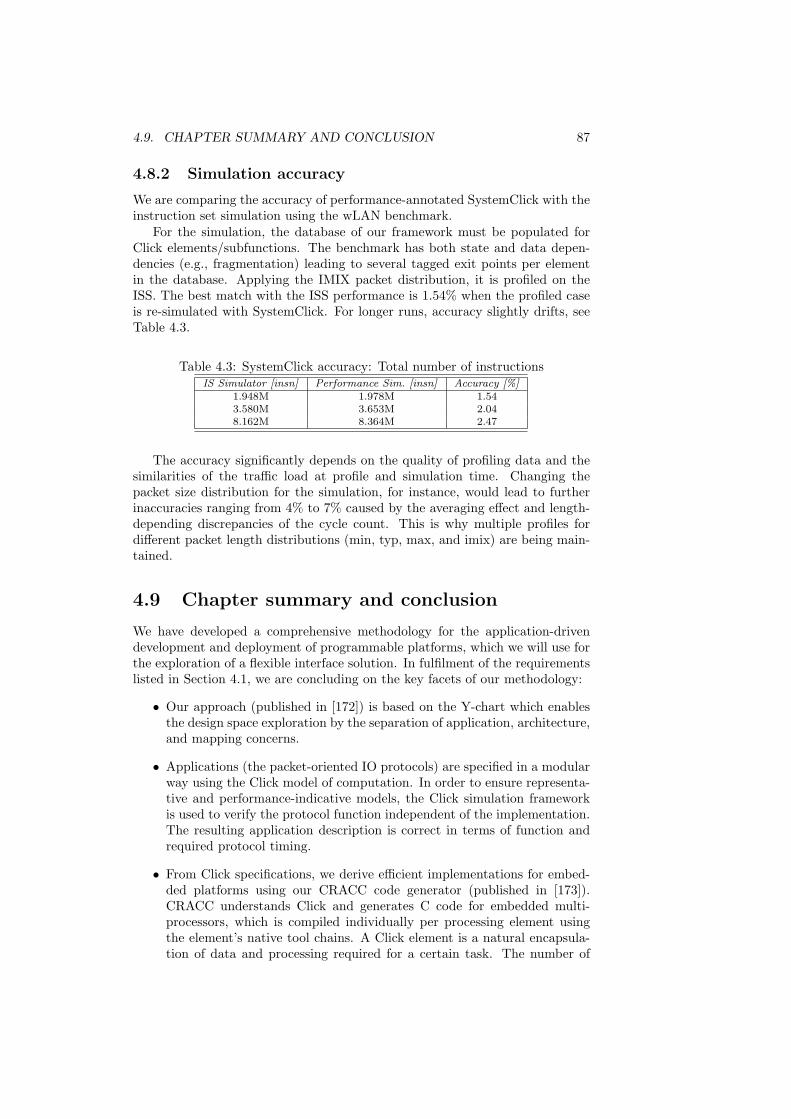
4.9. CHAPTER SUMMARY AND CONCLUSION 87
4.8.2 Simulation accuracy
We are comparing the accuracy of performance-annotated SystemClick with theinstruction set simulation using the wLAN benchmark.
For the simulation, the database of our framework must be populated forClick elements/subfunctions. The benchmark has both state and data depen-dencies (e.g., fragmentation) leading to several tagged exit points per elementin the database. Applying the IMIX packet distribution, it is profiled on theISS. The best match with the ISS performance is 1.54% when the profiled caseis re-simulated with SystemClick. For longer runs, accuracy slightly drifts, seeTable 4.3.
Table 4.3: SystemClick accuracy: Total number of instructionsIS Simulator [insn] Performance Sim. [insn] Accuracy [%]
1.948M 1.978M 1.543.580M 3.653M 2.048.162M 8.364M 2.47
The accuracy significantly depends on the quality of profiling data and thesimilarities of the traffic load at profile and simulation time. Changing thepacket size distribution for the simulation, for instance, would lead to furtherinaccuracies ranging from 4% to 7% caused by the averaging effect and length-depending discrepancies of the cycle count. This is why multiple profiles fordifferent packet length distributions (min, typ, max, and imix) are being main-tained.
4.9 Chapter summary and conclusion
We have developed a comprehensive methodology for the application-drivendevelopment and deployment of programmable platforms, which we will use forthe exploration of a flexible interface solution. In fulfilment of the requirementslisted in Section 4.1, we are concluding on the key facets of our methodology:
• Our approach (published in [172]) is based on the Y-chart which enablesthe design space exploration by the separation of application, architecture,and mapping concerns.
• Applications (the packet-oriented IO protocols) are specified in a modularway using the Click model of computation. In order to ensure representa-tive and performance-indicative models, the Click simulation frameworkis used to verify the protocol function independent of the implementation.The resulting application description is correct in terms of function andrequired protocol timing.
• From Click specifications, we derive efficient implementations for embed-ded platforms using our CRACC code generator (published in [173]).CRACC understands Click and generates C code for embedded multi-processors, which is compiled individually per processing element usingthe element’s native tool chains. A Click element is a natural encapsula-tion of data and processing required for a certain task. The number of
88 CHAPTER 4. AN APPLICATION-DRIVEN METHODOLOGY
mapping and partitioning choices can thus be reduced considerably to aset of rational alternatives.
• As a modular and programmable platform for packet processing applica-tions, we have introduced NOVA (published in [166]). NOVA is based onunifying sockets and common packet passing and communication infras-tructure for integrating various building blocks. Heterogeneous NOVAmultiprocessors can be programmed intuitively and productively in theCRACC framework. Our results show that the overhead of hardware andsoftware modularity is reasonable for NOVA compared to state-of-the-arttechniques and that NOVA is usable for systematic application-driven de-sign space exploration.
• For early design space exploration, we have presented the SystemClickframework (published in [171]). SystemClick abstracts platform archi-tectures as sets of shared resources, which arbitrate communication andcomputation tasks and consume time. From application, architecture,and mapping specifications, the framework generates SystemC simulationmodels that can be executed natively using a performance database. In-dicative performance data is derived, e.g., from profiling partial CRACC/NOVA implementations. The combination of performance modeling andfunctional correctness enables the quantitative assessment of implementa-tion alternatives for timing critical protocols. Sensitive design parameterssuch as the arbitration of shared resources and granularity of processingkernels are exposed to the designer. The integration with SystemC finallyallows the reuse of simulation and analysis as well as refinement infras-tructure.
In the next chapter, we will deploy our exploration tools and methodology toinvestigate the feasibility of a programmable interface platform.

Chapter 5
A ProgrammableArchitecture forPacket-orientedCommunication Interfaces
This chapter investigates the feasibility of a programmable platform for packet-oriented communication interfaces.
Programmable solutions are particularly interesting for the implementationof the discussed standards since they provide us with a platform for all pro-tocols and allow us to adapt to late changes in the specifications. Rememberthat the processing of the investigated communication protocols is a peripheralservice to the SoC’s main processing core, i.e. this peripheral is separate fromthe micro-architecture of the multi-processor system-on-chip, as it is currentlydeployed. This section will elaborate on the question whether existing buildingblocks of a processing platform such as processing engines and communicationinfrastructure can be used again in order to implement the peripheral function-ality.
Following our application-driven methodology of the last chapter, we willfirst look at a fully programmable solution based on an embedded standardcore. Such a solution is most flexible as all functions are software, implementedin plain (and portable) ANSI-C, and there is no special purpose hardware. Thissolution is a corner case of an implementation and provides the necessary datafor the exploration of the design space along several axis. Analyzing the perfor-mance, we quantitatively explore the design space with respect to number andtype of cores, instruction set extensions, application-specific hardware acceler-ators, and communication topology. This results in an optimized architecture,which will be presented toward the end of this chapter. Furthermore, for theanalysis, we quantify the overhead which is introduced by the modularity of thehardware/software platform and compare our solution with related work.
89

90 CHAPTER 5. A PROGRAMMABLE INTERFACE ARCHITECTURE
5.1 Fully programmable solution
For the profiling and analysis of the fully programmable solution, we will lookat two protocols, PCI Express and wireless LAN. PCI express has the high-est throughput requirements while wLAN requires the most complex protocolprocessing. Their joint requirements are the worst-case to be supported.
5.1.1 Architecture setup
Figure 5.1 shows the architecture of a fully programmable system based on asingle embedded core. The module only comprises the processing core, its in-struction and data memories, and memory-mapped transfer queues. All protocolfunctions are implemented in software on the embedded core.
Memories and transfer queues can be accessed with one cycle latency, i.e.they run at the same frequency as the processing core. The data memory has anextra interface to the SoC core which is used to transfer transactions betweenSoC core and IO module concurrently to the IO module operation.
In transmit direction data flows through the architecture as follows: an out-bound transaction is stored in the data memory (1) and the associated messagecomprising the packet descriptor is sent to the module (2). The core reads thedescriptor from its inbox (3) and processes the packet as specified by the Clicktask graph (4). If required, the packet is queued and scheduled (5) before itsdata and extra processing information can be sent to the PHY queue (6).
On-
chip
Inte
rcon
nect
CPU
I-MEM
PHY
Function
Data
Mem
1
5
32
4
6
Figure 5.1: Fully programmable single-core architecture. All building blocksrun at the same clock frequency. Fifos and the dual-port memory synchronizewith the environment.
Not shown in Figure 5.1 is the additional PHY status register (read-only)which maps important state of the PHY function directly into the CPU memoryspace. It may be used to access (pull) the immediate link state, e.g., carrier sensein the case of Ethernet and wireless Lan. Its use is optional and depends on theprotocol implementation. Alternatively, PHY processing state notifications canbe generated (pushed) using the PHY queue as mentioned before.
Note that the protocol-specific PHY function consistently includes frame-ing/deframing for all protocols. While this is consistent with the standard formost protocols, GbE requires some adaptation logic to connect to standardcompliant PHYs (GMII interface).

5.1. FULLY PROGRAMMABLE SOLUTION 91
5.1.2 Profiling results
For the profiling and the analysis of the fully programmable architecture, wewill examine two protocols, PCI Express and wireless LAN. PCI express has thehighest throughput requirements. Wireless LAN requires the most complex pro-tocol processing. To report the results, we follow the different packet-processingpaths for receiving and transmitting packets as derived in Section 3.3. For eachpath the overall instruction counts are listed, which are based on the measure-ments of the individual functions. Those functions that contribute most areidentified and listed separately. The overhead of this architecture for task han-dling and packet communication will be quantified at the end of this section.
Profiling procedure
For the characterization at the granularity of Click elements, we cut our ap-plications into subgraphs. These subgraphs either contains multiple elementsthat are executed sequentially or they contain single elements that require care-ful simulation due to processing complexity and deep state such as the DCFfunction of the wLAN model. Each subgraph is mapped individually onto theprocessor target using the CRACC code generator as described in Section 4.4.CRACC generates modular and portable ANSI-C code suited for a range of pro-cessors. We chose the MIPS family of embedded processors since it provides agood performance/area foot print as will be shown later (cf. Fig. 5.6). The coreinteracts with its surroundings as described in the previous section (Sec. 5.1.1).
Profiling uses the core vendors tool chain which is based on GNU’s compiler,gprof profiler, and comes with the cycle-precise MIPS-sim simulator. The toolsare incorporated into our work flow. Compilation throughout the profiling pro-cess was carried out with -O2 and -O3 optimization. Simulation statistics arepost-processed to extract results per Click element. As GProf relies on a func-tion call graph produced by instrumented code, two separate simulation runsare used to achieve more accurate results without profiling overhead.
The measurement results reflect the computation per packet and functionfor a constant packet stream without bursts. The CPU is assumed idle withonly one task graph running. This separates the effects of traffic characteris-tics and resource availability from the actual computation and communication.The measurements were executed with four different packet size distributionsfollowing the simple Internet protocol mix [2]: Minimum (64 B), Typical (550B), Maximum (1498 B), Simple iMix (7:4:1).
PCI Express execution profile
The profile of executed instructions for the processing paths of PCI-Expressis listed in Table 5.1. The table lists the common Cyclic Redundancy Check(CRC) function separately since its profile depends on the packet length. Theremainder of the processing only accesses the packet header and is independentof the packet length. Thus, the number of executed instructions, e.g., for anoutbound transaction of minimal size is 331 + 652 = 983 instructions. Thatmakes path A the most instruction-consuming case. Link layer packets foracknowledges and flow control are only 6 bytes long.

92 CHAPTER 5. A PROGRAMMABLE INTERFACE ARCHITECTURE
Table 5.1: Single packet instruction counts for the PCI express model.
Path Description Instructions / packet sizemin typ max imix
A Outbound transaction 331B Inbound transaction 205
C Outbound Acknowledge* 77D Inbound Acknowledge* 255
E Flow control (Tx)* 65F Flow control (Rx)* 163
Common functions+ CRC 652 6285 16712 3868
*) The frame length of control frames is 6 Bytes.
Wireless LAN execution profile
Table 5.2 summarizes the profiling results for the different processing paths ofthe wLAN model. Figure 5.2 shows the corresponding diagram. The instructioncounts for encryption and CRC calculation are listed separately as before.
Table 5.2: Single packet instruction counts for the wireless LAN model.
Path Description Instructions / packet sizemin typ max imix
A Outbound dataframe 2326 2618 2591 2445B Inbound dataframe 1151 1251 1171 1186
C Ackn Tx [16B]** 510D Ackn Rx [16B]** 739
G RTS tx, CTS rx** 1443H RTS rx, CTS tx** 1363
I Management Tx* 3132J Management Rx* 3250
Common functions+ CRC 652 6285 16712 3868+ Encryption (WEP) 8515 31464 74129 32299+ Decryption (WEP) 8478 31427 74091 32262
*) Beacons. **) The frame length of control frames is 14-20 Bytes.
The results show the handling of management frames, i.e. beacon generationand reception, to be the most compute-intense processing paths. However,management frames are processed relatively infrequently compared to data andcontrol frames. Beacons, for instance, are generated in tens to hundreds ofmilliseconds intervals, and are therefore not performance-critical. Of the morefrequent data and control frames, the transmission of data frames in outbound

5.1. FULLY PROGRAMMABLE SOLUTION 93
0
500
1000
1500
2000
2500
3000
3500
A
Outbound
Data
B
Inbound
Data
C
Outbound
Acknowledge
D
Inbound
Acknowledge
E
Outbound RTS /
Inbound CTS
F
Inbound RTS/
Outbound CTS
G H
Generate
Beacon
Receive
Beacon
Data frames Control frames Management frames
Outbound Inbound
Max
Typ
IMix
Min
Figure 5.2: Single packet instruction counts per processing path for wLANexcluding CRC and WEP functions.
direction is the most instruction consuming case.Since most of the payload-dependent processing can be attributed to the
CRC and crypto (WEP) functions, the numbers do not depend on the packetlength much. The little influence left is due to fragmentation and reassemblyrelated rate changing effects.
Overhead for communication and task handling
In addition to the protocol function, the overhead for packet IO must be takeninto account. This means that not only the memory-to-memory packet pro-cessing on a CPU system must be considered but also the processing overheadrequired to transfer the packet, i.e. the descriptor and/or the packet data fromthe inbound interface into the memory and from there back to the outboundinterface. In case of the fully programmable solution, which relies on the CPUfor the data movement, the overhead includes:
• SoC interface inbound — Packet descriptor messages from the SoC coreare received in the inbox. They are read by the CPU and stored in datamemory. Then, the associated task chain is identified and started.
• SoC interface outbound — A local packet descriptor is moved from thelocal data memory into the outbox.
• PHY interface outbound — Packet context and packet data are movedfrom the data memory into the outbound PHY fifo.
• PHY interface inbound — Packet context and packet data are read fromthe inbound PHY fifo and stored in the local memory. In the process, apacket descriptor is generated and the protocol task chain is started.
The number of required instructions depends on the amount of data thatare transferred and the number of tasks that reside on the processor. Table 5.3
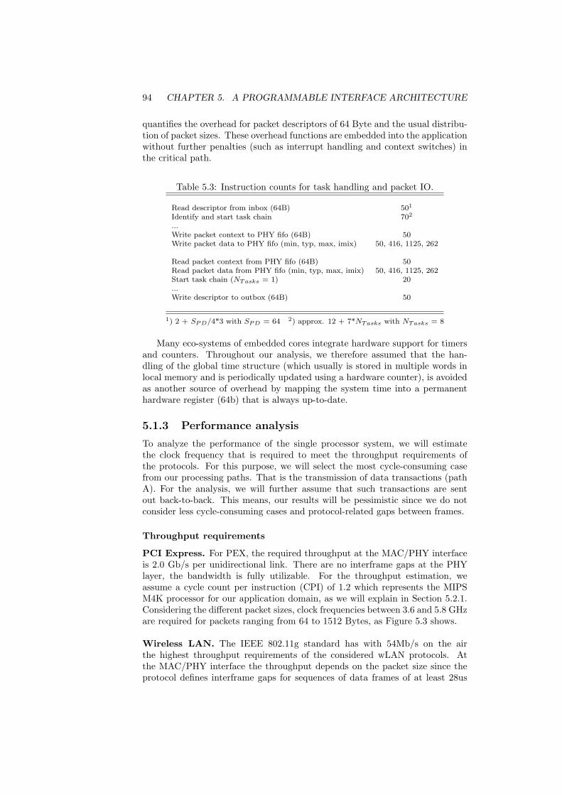
94 CHAPTER 5. A PROGRAMMABLE INTERFACE ARCHITECTURE
quantifies the overhead for packet descriptors of 64 Byte and the usual distribu-tion of packet sizes. These overhead functions are embedded into the applicationwithout further penalties (such as interrupt handling and context switches) inthe critical path.
Table 5.3: Instruction counts for task handling and packet IO.
Read descriptor from inbox (64B) 501
Identify and start task chain 702
...Write packet context to PHY fifo (64B) 50Write packet data to PHY fifo (min, typ, max, imix) 50, 416, 1125, 262
Read packet context from PHY fifo (64B) 50Read packet data from PHY fifo (min, typ, max, imix) 50, 416, 1125, 262Start task chain (NTasks = 1) 20...Write descriptor to outbox (64B) 50
1) 2 + SPD/4*3 with SPD = 64 2) approx. 12 + 7*NTasks with NTasks = 8
Many eco-systems of embedded cores integrate hardware support for timersand counters. Throughout our analysis, we therefore assumed that the han-dling of the global time structure (which usually is stored in multiple words inlocal memory and is periodically updated using a hardware counter), is avoidedas another source of overhead by mapping the system time into a permanenthardware register (64b) that is always up-to-date.
5.1.3 Performance analysis
To analyze the performance of the single processor system, we will estimatethe clock frequency that is required to meet the throughput requirements ofthe protocols. For this purpose, we will select the most cycle-consuming casefrom our processing paths. That is the transmission of data transactions (pathA). For the analysis, we will further assume that such transactions are sentout back-to-back. This means, our results will be pessimistic since we do notconsider less cycle-consuming cases and protocol-related gaps between frames.
Throughput requirements
PCI Express. For PEX, the required throughput at the MAC/PHY interfaceis 2.0 Gb/s per unidirectional link. There are no interframe gaps at the PHYlayer, the bandwidth is fully utilizable. For the throughput estimation, weassume a cycle count per instruction (CPI) of 1.2 which represents the MIPSM4K processor for our application domain, as we will explain in Section 5.2.1.Considering the different packet sizes, clock frequencies between 3.6 and 5.8 GHzare required for packets ranging from 64 to 1512 Bytes, as Figure 5.3 shows.
Wireless LAN. The IEEE 802.11g standard has with 54Mb/s on the airthe highest throughput requirements of the considered wLAN protocols. Atthe MAC/PHY interface the throughput depends on the packet size since theprotocol defines interframe gaps for sequences of data frames of at least 28us

5.1. FULLY PROGRAMMABLE SOLUTION 95
1 10 100 1000 10000
Packet Size [Byte]
Req
uire
dF
requ
ency
[MH
z]
Min Typ Max
37875
20700
12113
7819
5672
45984062 3793
3659
3616
35923559
1000
10000
100000
Figure 5.3: Required clock frequencies to meet PCI Express throughput require-ments depending on the packet size.
(DIFS time) and a PHY layer overhead that is equivalent to another 26us perpacket [49]. Due to this considerable overhead, clock frequencies between 223and 415 MHz are required. Largest contributors are CRC and WEP encryptionfunctions which require up to 96% of the cycles.
0 500 1000 1500 2000 2500
Packet Size [Byte]
Req
uire
dF
requ
ency
[MH
z]
Min Typ Max
223
254
296
343
385
404
415
200
250
300
350
400
450
Figure 5.4: Required clock frequencies for the 11g wLAN throughput dependingon the packet size.

96 CHAPTER 5. A PROGRAMMABLE INTERFACE ARCHITECTURE
Realtime requirements
PCI Express is latency-insensitive. Wireless Lan protocols, however, definefirm deadlines for transactions of stations and access points on the air, seeSection 3.3.5. For the MAC time budget most relevant is the timing for sendinga response for a just received frame.
16µs Context
20µs Frame Data
Inbound frameSIFS = 16µs
2µs
RF
12µs
RX PHY
2µs
MAC
Outbound response
Figure 5.5: MAC time budget for response frames.
A typical response time is 16 µs as defined in IEEE 802.11 [36]. In case of11g the time is defined as a 10 µs SIFS time plus an extra frame extension timeof 6µs. Since the interframe gap is defined on the air, the PHY receive andtransmit processing delays are included in the interval and must be subtracted.Figure 5.5 shows this in detail. In the Figure, the last byte of the inbound frameis given to the MAC by a Rx PHY only after 12 µs. The CRC can be calculatedand the MAC processing starts. For the response frame transmission, the TxPHY requires the frame data and context after different setup times. Afteronly 2 µs, the MAC must signal whether a transmission will follow. The framecontext is required after 16 µs. The first word of the frame itself finally mustbe available after 20 µs. For the purpose of the analysis in this chapter, we willfocus on the frame context deadline. In order to be met, this deadline requiresthe completion of the entire protocol processing.
Table 5.4: Estimate of the required clock frequencies for the realtime responseof 802.11 frames.
min max
Read data frame from PHY (PD+data) 100 1175CRC processing 652 16712Receive path processing 1151 1171WEP decryption (resource not available) 8478 74091
Scheduling Overhead 70 70Ack generation 510 510CRC processing 326 326Write context 50 50
Sum [Inst] 11337 94105Sum [Cycles, CPI=1.2] 13605 112926
Required frequency [MHz] 850 7058
Table 5.4 shows the required clock frequencies for meeting this deadline.Frequencies up to 7 GHz are necessary to support the required cycles. The tableassumes an idle resource which is available without delay for the processing of

5.2. DESIGN TRADE-OFFS AND CONSEQUENCES 97
the received frame. In this case, the decryption function shown in the tablewould not be part of the critical path since a packet can be decrypted afterits acknowledgement. On the other hand, the CPU may just have started theprocessing of a large tx frame (dominated by the encryption function) so thatthe WEP cycles represent the non-availability of the resource for a ballparkfrequency estimate. This will be discussed further in Section 5.2.4. Figure 5.15(p. 113) shows histograms of the processing jitter for a busy core.
5.1.4 Observations
The fully flexible single-core architecture cannot fulfill throughput and realtimerequirements in all cases considered. Especially the high throughput rates ofPCI Express are difficult to achieve. In the case of the 11g wireless LAN proto-col, the throughput requirement is moderate and would be achievable. However,the required deadline for the response generation cannot be met for larger frames(not even on an idle resource). To enable a processor based solution, the cy-cle counts must be reduced and the realtime critical path must be shortenedsignificantly.The performance analysis in particular revealed:
• Per-packet protocol processing — Most of the protocol processing happensper-packet and is based on the packet context only, which is correlatedwith the packet header. The context is either extracted from the headeror forms the header. The packet payload is rarely touched.
• Cycle-consuming per-byte payload processing — Those functions that ac-tually touch the whole packet such as CRC calculation encryption, frame-ing/deframing, are the most cycle-consuming functions.
• Non-deterministic processing times — The dependency of the payloadprocessing functions on packet length leads to irregular and monolithicprocessing which makes performance prediction and task scheduling diffi-cult if not impossible in some cases.
• Unexploited parallelism — The protocols exhibit data- and task-level par-allelism which would enable partitioning and mapping onto concurrentresources without data coherency problems.
Further design space exploration is required to find a feasible platform proposal.In the next section, we will therefore explore several axes of the platform designspace and discuss their impact on the system’s performance compared to thefully programmable single-core solution.
5.2 Design trade-offs and consequences
The required cycle counts for the fully flexible single-core architecture are toohigh for an implementation. This problem can be addressed by different designapproaches which will be individually explored and quantitatively analyzed inthe following subsections. The fully flexible single-core solution serves as base-line for this exploration of the platform’s design space.

98 CHAPTER 5. A PROGRAMMABLE INTERFACE ARCHITECTURE
5.2.1 Core type and configuration
To compare the performance of different RISC cores and their compilers, weprofiled packet processing functions implemented in CRACC on a representativeset of synthesizable embedded 32bit processors using cycle-accurate simulators.
For the analysis we assumed a 90nm Infineon technology under worst-caseoperating conditions. The cores were configured to there smallest area footprint.Wherever possible, we disabled unused options such as caches, and cache con-trollers. Most of the cores (PowerPC 405D, ARM926EJS [63], MIPS M4K [14],ARC600 [63]) have five pipeline stages and run at clock frequencies of 290 to440 MHz (Worst case). N-core [106] and ARM7 [5] have 3 pipeline stages, theprocessing engine [133] has 4. These cores run at frequencies of 160 to 270 MHz.
The results published in [173] reveal that among the modern general pur-pose 32bit RISC cores (ARM, MIPS, and PowerPC) the MIPS 4K has thebest performance/area trade-off for the packet processing application domain(cf. Figure 5.6). For this reason, the MIPS 4k is used as the primary core forour analysis.
300MHz
[Pkts/s]
[mm2]
MIPS
ARM7
ARM926
N-core
PowerPC
0
50k
100k
150k
200k
250k
0 0,1 0,2 0,3 0,4 0,5
Processing engine
Figure 5.6: Performance of selected processor cores over core area for a packetprocessing benchmark [173].
Among the smaller cores which trade off speed against area (ARM7, N-core)or deploy a much reduced instruction set (packet processing engine), the N-core would be a reasonable second choice. The N-core was developed to enableefficient modifications on micro-architecture and compiler simultaneously – asthey are necessary, e. g., for the exploration of ISA extensions. The Processingengine with its highly optimized but limited instruction set could not performwell. Performance improvements that are achieved with the specialized instruc-tions are annulled by insufficient general purpose instructions as matched by acompiler. Improvements could be achieved by coding critical parts manually inassembly. We will come back to these points later, in Section 5.2.3, where weanalyze the performance of an application-specific instruction set.
Core configurations
The impact of corner case configurations on the MIPS 4k’s performance is an-alyzed using the cycle-per-instruction (CPI) measure. To derive the CPI weprofiled the most complex application, wireless LAN, and measured elements

5.2. DESIGN TRADE-OFFS AND CONSEQUENCES 99
individually as well as the application as a whole. For the M4k, two configura-tion options proved to be relevant:
• Memory interface — Configured with a unified memory interface (as it wasused in the previous section) the M4k has a CPI of around 1.45. This isa significant performance penalty since the configuration with dedicatedinterfaces for instruction and data (Harvard architecture) requires only1.08 cycles per instruction.
• Fast multiply unit — The impact of removing the fast multiply unit israther small (CPI 1.13 vs. 1.08) and is limited to the few elements relyingon multiplications (e.g. those, that calculate transfer times in wLAN suchas SetDuration).
From the cycle-accurate profiling results for the M4K, the CPI ratio perprocessing path inside every Click element can be computed. These CPIs rangefrom 1.0 to 1.2 with an average of 1.06 over the CRACC application library. Thisis slightly better than the ratio for the complete application setup from above,which included more branches in code for scheduling and calls to push/pullfunctions. We therefore use 1.2 as the upper bound for our instruction-to-cyclecalculations in this chapter.
5.2.2 Application-specific hardware accelerators
Customized hardware accelerators can help to reduce the cycle-count require-ments for the communication protocols by offloading compute-intense tasks.Their impact on the system’s performance, however, depends on the way oftheir integration into a system. Before we discuss the performance impact, letus therefore first look at different integration patterns.
Accelerator integration
With respect to the flow of control and data hardware accelerators, can bedeployed following different strategies:
• Flow-trough (FT) processing — Flow-through coprocessors usually pro-cess data while they pass through the unit. The work in a pipelined fashionas pre- or post processors for the main processing unit.
• Lookaside (LA) processing — Lookaside accelerators are slaved to themain processing unit. They are operated similarly to function calls. Themain processing unit passes commands (function’s name) and data (pa-rameters of the function) to the accelerator and receives the results of theprocessing.
Flow-through engines can be designed to run fully autonomous and parallelto the processor. This means that they can offload all processing cycles fromthe processor without introducing extra overhead for communication and syn-chronization. LA engines, on the other hand, require processing cycles for thetransfer of information. Depending on the complexity of the operation theymay still run concurrently to the processor. But in this case extra overhead forsynchronization will be required in addition to the communication.

100 CHAPTER 5. A PROGRAMMABLE INTERFACE ARCHITECTURE
Performance impact
The execution profiles for the fully programmable solution are dominated bythe payload processing functions (cf. Tables 5.1 and 5.2). Offloading them tospecial purpose accelerators can relieve the cycle budget significantly.
This insight is not new. CRC units, for instance, are usually implementedin hardware and efficient flow-through solutions exist [70] and are being used innetwork processors. We therefore assumed full acceleration for this task.
Another cycle-consuming aspect is the processor’s involvement in the move-ment of data between transfer fifos and local memory. A DMA hardware ac-celerator, which moves the data from the transfer fifos into the local memoryand vice versa, could run concurrently to the processor and relieve it from thisburden. Such a DMA engine must be managed by the processor in a lookasidefashion. To enable decoupled operation, the coprocessor has inboxes (commandqueues) and outboxes (result queues). In a steady state, the processor initiatesa transfer (write) every time the result of the previous one (read) is consumed.Including status check, ten instructions are required for such a transfer.
Assuming hardware acceleration for CRC and a DMA engine for moving thepacket data, the overall system performance for PCI Express could be improvedas shown in Figure 5.7. With the accelerators, only the protocol processing isleft which is constant per packet so that the required clock frequency decreaseswith packet size. If the DMA engine is used for the packet descriptor as well,the IO overhead can be reduced further and the required cycles would decreaseby another 9%.
10
100
1000
10000
100000
1 10 100 1000 10000
Packet Size [Byte]
Req
uire
dF
requ
ency
[MH
z]
All SW CRC, DMA Full DMA
Min Typ Max
5672
36163559
2184
92
34
1997
85
31
37875
34950
31950
Figure 5.7: Impact of hardware accelerators for DMA and CRC on the requiredclock frequencies for PCI Express.
The same hardware accelerators for CRC and packet data DMA applied towireless LAN save up to 19% of the cycles as Figure 5.8 shows. In this case clockfrequencies up to 338 MHz are required. If the WEP encryption/decryption

5.2. DESIGN TRADE-OFFS AND CONSEQUENCES 101
elements are accelerated as well, the required frequency shrinks to less than 50MHz. However, encryption is only used by wireless LAN, and the required cy-cles are moderate. Multi-standard security coprocessors usually require consid-erable resources, see, for instance, the implementation in [187] which describesa (micro-) programmable coprocessor solution. Leaving encryption executed insoftware would, therefore, be an option in our case.
0
50
100
150
200
250
300
350
400
450
0 500 1000 1500 2000 2500
Packet Size [Byte]
Req
uire
dF
requ
ency
[MH
z]
All SW CRC, DMA CRC, DMA, WEP
Min Typ Max
223
254
296
343
385
404415
210
230
258
290
318330
338
4842
3323
1511 8
Figure 5.8: Impact of hardware accelerators for DMA, CRC, and WEP on therequired clock frequencies for wLAN.
5.2.3 Application-specific vs. general purpose ISA
This subsection explores the trade-offs in programmability and speed betweena general purpose and an application-specific instruction set (ISA). In order toderive computational requirements on an application-specific instruction set wedefine a processing engine with an micro architecture which is optimized forpacket processing. We then derive static profiling results for PCI-Express asthe specification with the highest throughput requirements, and compare theresults to our fully programmable solution.
Micro-architecture Model
As an application-specific instruction set processor (ASIP) targeted at packetprocessing tasks, it is clear that we need specialized instructions for bit-levelmasking and logical operations [133]. We therefore base our simplified micro-architecture model on the processing engine used for the comparison of cores inSection 5.2.1 which is comparable to the one published in [133]. We also assumesupport for a large number of general-purpose registers (GPRs) per thread.Intel’s processing engine [31], for instance, provides 64 GPRs per thread. We donot believe that the size of the register file is a limiting factor of our application.

102 CHAPTER 5. A PROGRAMMABLE INTERFACE ARCHITECTURE
Indeed, our analysis showed less than 30 registers used concurrently in the worstcase. We, therefore, do not discuss the influence of register spills in this context.The data path is assumed to be 32 bit as in all major network processors. Sincewe consider reliable protocols, the support for timers is mandatory. Hardwaretimers are implemented using special registers and can thus be accessed quickly(see also Section 5.1.2).
Simplified Instruction Set with Timing
The following instruction classes are used in order to statically derive the exe-cution profile of our Click elements. An application-specific, register-to-registerinstruction set is assumed to support bit-level masks together with logical, arith-metic, load, and store operations to quickly access and manipulate header fields.
• Arithmetic operations (A): additions and subtractions take one cycle.
• Logical operations (L): such as and, or, xor, shift, and compare (cmp),take one cycle.
• Data transfer operations:
– Load word (ldr) from memory: two cycles latency from embeddedRAM.
– Load immediate (ldi), move between registers (mvr): take one cycle.
– Store word (str) to memory: one cycle latency on embedded RAM.
• Branch instructions (B): two cycles latency (no consideration of delayslots).
Our Click elements are annotated with a corresponding sequence of assem-bler instructions that are needed to perform the task of the element. Theseassembler programs of course depend on particular implementation decisions,which will be described next.
Optimized Implementation
For the implementation, we assume an optimized implementation of Click taskchains (cf. Sec. 4.4.3). Click elements that belong to one chain are mapped tothe same thread of the processing engine and share temporary registers, e.g. apointer to the current packet descriptor does not need to be explicitly transferredto the next Click element. Furthermore, the code from Click elements withinpush and pull chains without branches on the same thread can be concatenatedso that jumps are avoided.
We assume the IO overhead for the ASIP to be the same as before. Themovement of the packet descriptor from and to the registers of the processingengine takes 18 cycles. Another 64 cycles are required for management andscheduling of a small set of software tasks.
Profiling Procedure
The static profiling of our Click elements is executed as follows: Given ourmodels in Click, we annotate each of the Click elements with the number ofassembler instructions that the described packet-processing engine would need
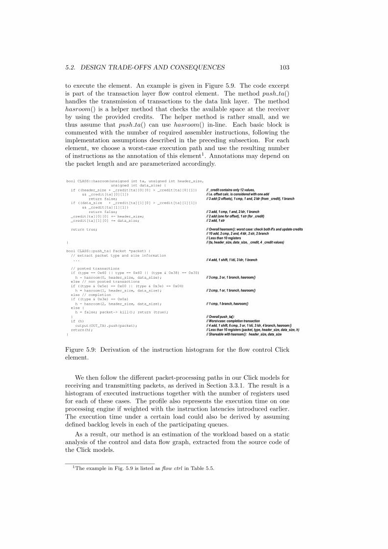
5.2. DESIGN TRADE-OFFS AND CONSEQUENCES 103
to execute the element. An example is given in Figure 5.9. The code excerptis part of the transaction layer flow control element. The method push ta()handles the transmission of transactions to the data link layer. The methodhasroom() is a helper method that checks the available space at the receiverby using the provided credits. The helper method is rather small, and wethus assume that push ta() can use hasroom() in-line. Each basic block iscommented with the number of required assembler instructions, following theimplementation assumptions described in the preceding subsection. For eachelement, we choose a worst-case execution path and use the resulting numberof instructions as the annotation of this element1. Annotations may depend onthe packet length and are parameterized accordingly.
bool CLASS::hasroom(unsigned int ta, unsigned int header_size,
unsigned int data_size) {
if ((header_size + _credit[ta][0][0] > _credit[ta][0][1]) // _credit contains only 12 values,&& _credit[ta][0][1]) // i.e. offset calc. is considered with one add
return false; // 3 add (2 offsets), 1 cmp, 1 and, 2 ldr (from _credit), 1 branchif ((data_size + _credit[ta][1][0] > _credit[ta][1][1])
&& _credit[ta][1][1])
return false; // 3 add, 1 cmp, 1 and, 2 ldr, 1 branch
_credit[ta][0][0] += header_size; // 2 add (one for offset), 1 str (for _credit)_credit[ta][1][0] += data_size; // 2 add, 1 str
return true; // Overall hasroom(): worst case: check both if’s and update credits// 10 add, 2 cmp, 2 and, 4 ldr, 2 str, 2 branch
// Less than 10 registers} // (ta, header_size, data_size, _credit, 4 _credit values)
bool CLASS::push_ta( Packet *packet) {
// extract packet type and size information
... // 4 add, 1 shift, 1 ldi, 3 ldr, 1 branch
// posted transactions
if (type == 0x40 || type == 0x60 || (type & 0x38) == 0x30)
h = hasroom(0, header_size, data_size); // 3 cmp, 2 or, 1 branch, hasroom()else // non posted transactions
if ((type & 0x5e) == 0x00 || (type & 0x3e) == 0x04)
h = hasroom(1, header_size, data_size); // 2 cmp, 1 or, 1 branch, hasroom()else // completion
if ((type & 0x3e) == 0x0a)
h = hasroom(2, header_size, data_size); // 1 cmp, 1 branch, hasroom()else {
h = false; packet-> kill(); return (true);
} // Overall push_ta():if (h) // Worst-case: completion transaction
output(OUT_TA).push(packet); // 4 add, 1 shift, 6 cmp, 3 or, 1 ldi, 3 ldr, 4 branch, hasroom()return(h); // Less than 10 registers (packet, type, header_size, data_size, h)
} // Shareable with hasroom(): header_size, data_size
Figure 5.9: Derivation of the instruction histogram for the flow control Clickelement.
We then follow the different packet-processing paths in our Click models forreceiving and transmitting packets, as derived in Section 3.3.1. The result is ahistogram of executed instructions together with the number of registers usedfor each of these cases. The profile also represents the execution time on oneprocessing engine if weighted with the instruction latencies introduced earlier.The execution time under a certain load could also be derived by assumingdefined backlog levels in each of the participating queues.
As a result, our method is an estimation of the workload based on a staticanalysis of the control and data flow graph, extracted from the source code ofthe Click models.
1The example in Fig. 5.9 is listed as flow ctrl in Table 5.5.

104 CHAPTER 5. A PROGRAMMABLE INTERFACE ARCHITECTURE
Execution profile
The profile of executed instructions using the instruction classes introducedearlier for the major Click elements for PCI-Express are listed in Table 5.5.
Table 5.5: Profile for PCI-Express Click elements. The marked elements (*) arerealized in hardware.
Instruction class A L ldr ldi str B
Click element/subfunction, 64 Byte data packetflow ctrl 14 14 7 1 2 6Ack/Nack Tx 5 5 1 0 6 0prio sched 0 1 1 0 0 0check paint 1 1 1 0 0 0Ack/Nack Rx 3 2 4 0 1 1classify 2 1 2 0 0 1flow ctrl rx 8 8 6 3 5 0
Ack/Nack packet-specificAckNackGen 0 0 0 4 1 0Ack/Nack Tx ack 7 9 2 0 1 1Ack/Nack Tx nack 4 9 22 1 3 1
Flow control packet-specific (in TaFl)flow ctrl update (Rx) 1 4 1 4 0 0ctrl hasRoom (Tx) 10 4 4 0 2 2ctrl newCredit (Tx) 8 2 3 0 2 3
commonCalc CRC* 64 320 144 64 0 0descr enqueue 2 2 0 0 4 0descr dequeue 2 2 4 0 0 0payload enqueue* 3 3 1 1 16 0payload dequeue* 3 2 16 1 1 0
The profiles listed in the table reflect the computation requirement for onepacket. We assume that one packet must be retransmitted if a Nack packet isreceived and that the priority scheduler only has to check one queue for its size.The requirement for the scheduler listed in the table is low since enqueue anddequeue operations are counted separately. Classifications are simple since theyonly rely on small bitfields for packet and transaction types so that they can beimplemented using table lookup.
Performance Impact
Given the profiling results in the form of instruction histograms for the differentprocessing paths, we now derive execution times by weighting the histogramswith the corresponding execution latencies per instruction class. Comparedto the cycle counts for the general purpose core, reductions between 39% and68% are observable, as Figure 5.10 reveals. The figure shows the absolute andrelative cycle counts per processing path. For the comparison, identical sets ofhw accelerators (CRC, DMA) and the same IO overhead were assumed.

5.2. DESIGN TRADE-OFFS AND CONSEQUENCES 105
0
100
200
300
400
500
600
A B C D E F
GP ISA (MIPS)
ASIP (processing engine)
Processing Paths
Req
uire
dC
ycle
s
41%
45%
46%
32%
52%
61%
Figure 5.10: Comparison of the required cycles for general purpose andapplication-specific ISA for PCI Express.
For the ASIP, Case A - the transmission of transactions - remains the mostcycle-consuming case. The relative cycle reduction of about 60% directly trans-lates into a reduction of the required clock frequency as Figure 5.11 shows.
10
100
1000
10000
100000
1 10 100 1000 10000
Packet Size [Byte]
Req
uire
dF
requ
ency
[MH
z]
Min Typ Max
31950
15975
7988
3994
1997
998
499
250
125
8562
31
12600
6300
3150
1575
788
394
197
98
49
3325
12GP ISA ASIP ISA
Figure 5.11: Impact of an application-specific ISA on the required clock fre-quencies for PCI Express.
5.2.4 Multiple processors
Multiple processing elements can help to meet performance requirements byexploiting task- and data-level concurrency of an application. This is especiallyobservable in the field of network processor architectures which is known forthe deployment of parallel cores in varying topologies for highest throughput

106 CHAPTER 5. A PROGRAMMABLE INTERFACE ARCHITECTURE
requirements [57]. This subsection applies the general principles observed innetwork processors to the particular domain of communication interfaces byinvestigating the impact of multiple processors on the performance.
Multiprocessor setup
For the exploration, we assume an allocation of homogeneous processing ele-ments. Similar to the baseline architecture (cf. Figure 5.1), each processingelement has its own instruction and data memory, and a set of transfer queuesfor the inter PE communication which supports direct communication betweentwo processing elements. Thus, we do not depend on SRAM or scratchpad mem-ory, since the message passing communication between tasks is either mappedto direct connections between two engines or processed internally if the corre-sponding tasks are mapped to the same engine.
The surrounding SoC and PHY system remains the same as in our baselinearchitecture but incorporates a DMA coprocessor for the transfer from packetsbetween PHY and packet memory. The coprocessor has a similar set of transferqueues to participate in the message passing communication. Access to thepacket memory will be possible for the PEs but is not required since the packetdescriptor contains all of the relevant data (i.e., processing state and packetheader).
The topology of multiprocessor setups can be characterized using two axes,namely the number of processing elements per stage in a pipeline and the num-ber of pipeline stages. In network processing, which is tailored to packet for-warding, we find all varieties of topologies ranging from fully pipelined to fullypooled solutions. We, therefore, assume an interconnection network which cansupport arbitrary topologies and enables the communication between any of theprocessing elements including the DMA coprocessor.
To separate the effects of computation and communication, the interconnectnetwork is assumed to be ideal. Transfers do not consume time and the networkis always available. In a separate exploration step (Section 5.2.5), the effects oftransport delay and resource sharing are considered.
Expected performance speedup
Multiple processors can help to reduce the required clock frequency for thedeployed cores by distributing the load (in settings with given throughput andprocessing requirements). For the following analysis, we, therefore, define theperformance gain as the ratio of the required clock frequencies for single (fs)and multi-core systems (fi):
Speedup =fs
maxi=1..N fi(5.1)
The single-core frequency fs is the product of the required bandwidth (BWIO)and the number of cycles to be executed (CIO). If an application can be par-titioned evenly and mapped without overhead for communication and synchro-nization among N cores, the speedup is ideal and equals the number of process-ing cores:
Speedup = N with fi =BWIO ∗ CIO
Nand fs = BWIO ∗ CIO (5.2)

5.2. DESIGN TRADE-OFFS AND CONSEQUENCES 107
Such an ideal speedup would be achievable in pooled settings, in which everycore executes the complete and statically assigned task graph for a stream ofdata tokens independently of other cores without sharing of processing state.However, such settings are limited to cases where the computation requirementof the task graph is below the inter-arrival time of packets in the data stream.In the more general case, some degree of pipelining is necessary, e.g., to classifyand distribute data (streams) among the processors or to match the inter-arrivaltime of packets within the stream.
Taking into account the overhead for communication of packet descriptorsCPD in a pipeline of processing elements with N stages and the overheadfor scheduling and arbitration on each processing element CS , the achievablespeedup becomes limited and saturates:
Speedup = N ∗ CIO
CIO + (N − 1)(CPD + CS)(5.3)
limN→∞
Speedup =CIO
(CPD + CS)(5.4)
This behavior is shown in Figure 5.12 which plots the calculated speedupfor PCI Express, transmission of data packets, considering communication andscheduling overhead. The non-linear scheduling overhead depends on the num-ber of tasks mapped onto a core and therefore ranges from 68 instructions (8tasks, 1 core) down to 19 instructions (1 tasks, > 7 cores). The communicationoverhead is 20 instructions.
2
3
4
5
6
7
8
1
1,79
2,47
3,14
3,614,01
4,75,05
6,83
8,3
9,29
9,8910,22
0
2
4
6
8
10
1 10 100 1000
Number of cores
Spe
edup
ideal Including overhead
Figure 5.12: Theoretical speedup for PCI Express (Path A, data tx on MIPScores) considering a) an ideal pooled setup (Eq. 5.2), and b) communicationand scheduling overhead for a pipelined setup (Eq. 5.3).
The performance gain in the figure is calculated under the ideal assumptionthat the single task graph can be well-balanced even for high core numbers.Now, the challenge is to extract sufficient concurrency from the application andto take the effects of multiple task graphs into account.

108 CHAPTER 5. A PROGRAMMABLE INTERFACE ARCHITECTURE
Application concurrency
The packet-oriented communication interfaces, as modeled and discussed inChapter 3.3, exhibit only a limited degree of data- and task-level concurrencycompared to typical multi-ported packet-forwarding applications (such as theones described, e.g., in [57, 174]). In particular, we observed:
• A limited number of concurrent packet flows — Multiple physical IO portswould be a natural source for data-level parallelism since each of themhandles independent packet flows. Communication interfaces, however,have exactly one physical IO port with, at best (full duplex), two trulyconcurrent packet streams, receive and transmit. Even though a smallnumber of logically independent streams exists at the transaction layer(such as the three quality-of-service classes in PCI Express), multiplexingand joint stateful processing of these streams is required at the link layer.
• Fair task-level concurrency — The different processing paths of the com-munication interfaces as identified in Chapter 3.3 represent independenttask chains which may execute concurrently. Each of the processing chainscomprises several Click elements thus enabling pipelining. In case of PCIExpress, for instance, between 3 to 6 elements are instantiated.
These observations indicate that only settings with small numbers of process-ing cores are meaningful for the interfaces. In the following, we will, therefore,focus on setups between one and seven cores. We focus on the PCI Expressprotocol, which has the highest throughput requirements and is latency insen-sitive. Only at the end of this section shall we come back to wireless Lan andreport the results of its exploration.
Application setup and partitioning
For the performance analysis of the PCI Express model, we configure the simula-tion for the transmission of a continuous stream of packets between to interfaces.For proper operation, two PCI Express lanes are required. The first, from if1to if2 transmits the data packets while the second, from if2 to if1, is used forreturning acknowledge and flow control credits.
Following our CRACC mapping approach as described in Section 4.5, wepartition the application at element boundaries as shown in Figure 5.13 andmap the subgraphs to different MP configurations. The longest processing pathis partitioned into two subgraphs at the border between TA and DL layer.The inter-PE communication links are configured to be ideal, representing, forinstance, dedicated point-to-point connections.
Performance impact
To study the impact of the concurrent receive and transmit processing tasks for aduplex PCI Express interface, we start with a single processor mapping (named1CPU). In this case, a CPU frequency for if1 is required that is 18% higherthan for the data transmission, only. Running at the same clock frequency asif1, the core of if2, which receives the data and generates the feedback is utilizedby 92%, i.e., the required frequency is 6.7% higher than the pure data tx case.

5.2. DESIGN TRADE-OFFS AND CONSEQUENCES 109
FC
cou
nter
s
Prio
rityS
ched
TaFlTx
Paint(2) SetSeqN SetCRC32
ReplayBuf Trigger(4)
Tim
eout
Tee
Cec
kSeq
N
AckNackTx
AckNackTx
Paint(0) SetCRC16
Che
ckP
(2)
Discard
ChCRC32
Tim
eout
GenAck/N
ChSeqN
Che
ckP
(0)
AckNackRx
ChCRC16
Cla
ssify
Discard
GenFlUpd
Fl cntr++
Timeout
Cla
ssify
Tee
State
…
…
Ta-dll
flw-dll
ack-dll
dll-ackdll-flw
dll-ta
ch1
ch1
ch2
p0
gen
Figure 5.13: Partitioning of the PCI Express model for the MP simulation.
This data is derived from Figure 5.14 which shows the utilization of the coreslabeled ”1CPU.tx” for if1 and ”1CPU.rx” for if2 to be reasonably well balanced.
In the next step, we map the transaction and the link layer on two differentprocessors (2CPU). In this case, an overall speedup of 1.44 is achieved for thecombined processing on if1, which is less than expected. Figure 5.14 reveals theDLL layer CPU (CPU.tx.2) to be the bottleneck in the system. The CPU isfully utilized but only 80% of the load are caused by the transmit task. Almost20% of the load are due to the reception of link layer feedback packets, i.e.,acknowledgements and flow control credits.
To relieve the DLL layer CPU, we now consider a four core mapping (4CPU)for the interface by separating both receive and transmit parts of both layers.We do not expect much utilization for the two receive cores of if1, since ourtraffic pattern only transfers data from if1 to if2. Vice versa, if2 should notutilize the transmit cores much. This expectations are confirmed by Figure 5.14,cases 4CPU.tx.1-4 for if1, and 4CPU.rx.1-4 for if2. Interestingly, we achieveonly a small reduction of the rx load on core #2 which leads to a slightlyimproved speedup of 1.51. The remaining rx load is caused by the processingof received acknowledges within the AckNackTx element, which is also part ofthe Tx processing task chain.
To consider a fully loaded 4-core system, we finally use a symmetric traf-fic setup in which if1 simultaneously sends and receives packets. The overallspeedup in this case is 1.6. CPU #2, again, is fully utilized and remains thecomputational bottleneck (cf. Fig. 5.14). The other cores are between 70% and90% utilized.
In all mapping variants, the overall speedup is dominated by the partitioningof the most compute intense task chain, the transmission of data packets. Ta-ble 5.6 shows this in detail. The monolithic AckNackTx element consumes 205instructions and basically is the only element on CPU 2. Further performanceimprovement therefore requires optimization of this bottleneck by one of thefollowing options:
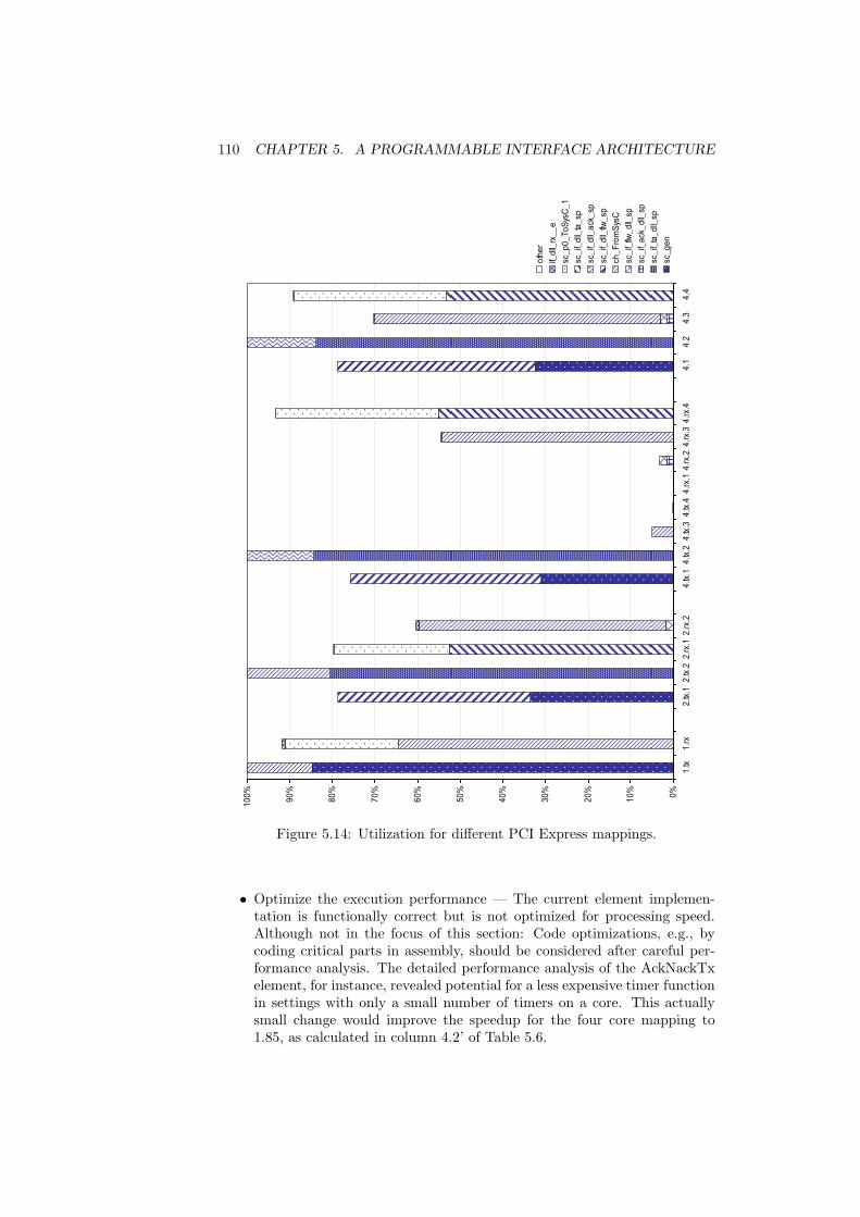
110 CHAPTER 5. A PROGRAMMABLE INTERFACE ARCHITECTURE
0%
10
%
20
%
30
%
40
%
50
%
60
%
70
%
80
%
90
%
10
0%
1.tx
1.r
x2
.tx.1
2.tx
.22
.rx.
12
.rx.
24
.tx.1
4.tx
.24
.tx.3
4.tx
.44
.rx.
14
.rx.
24
.rx.
34
.rx.
4 4
.1 4
.2 4
.3 4
.4
oth
er
if_d
ll_rx
__
e
sc_
p0
_T
oS
ysC
_1
sc_
if_d
ll_ta
_sp
sc_
if_d
ll_a
ck_
sp
sc_
if_d
ll_flw
_sp
ch_
Fro
mS
ysC
sc_
if_flw
_d
ll_sp
sc_
if_a
ck_
dll_
sp
sc_
if_ta
_d
ll_sp
sc_
ge
n
Figure 5.14: Utilization for different PCI Express mappings.
• Optimize the execution performance — The current element implemen-tation is functionally correct but is not optimized for processing speed.Although not in the focus of this section: Code optimizations, e.g., bycoding critical parts in assembly, should be considered after careful per-formance analysis. The detailed performance analysis of the AckNackTxelement, for instance, revealed potential for a less expensive timer functionin settings with only a small number of timers on a core. This actuallysmall change would improve the speedup for the four core mapping to1.85, as calculated in column 4.2’ of Table 5.6.

5.2. DESIGN TRADE-OFFS AND CONSEQUENCES 111
Table 5.6: Partitioning of the most critical PCI Express task chain.
Mapping/core 1 2.1 2.2 4.1 4.2 4.2’ 4.1” 4.2”No. of chains 7 5 5 3 3 3 3 3
Read PD 10 10 10 10 10 10 10 10schedule chain 61 47 47 33 33 33 33 33TaFlTx.push 51 51 51 51Paint 29 29 29 29AckNackTx.push 135 135 135 135 35 100Write PD 10 10 10 10 10 10 10 10AckNackTx.timer 70 70 70 35 70TaFlTx.pop 30 30 30 30Dequeue 17 17 17 17Total [inst] 413 194 272 180 258 223 215 223Speedup 1 2.13 1.52 2.29 1.60 1.85 1.92 1.85
• Partition critical element, optimize mapping — Partitioning of large ele-ments eases the balancing of pipeline stages. In case of the AckNackTxelement and its transmit path three only loosely associated parts can beidentified2: set sequence number (35), enqueue & push (100), and resched-ule timer (70/35). A separate SetSeqN element, for instance, which ismapped onto tx.1 would lead a speedup of 1.85 as well. If combinedwith the timer optimization above, the other CPU becomes the bottle-neck resulting in a speedup of 1.92 for the transmit path. Instantiatingan additional CPU in this path would increase the speedup to 2.19 (seethe 5-core case in Table 5.7).
• Replicate element, distribute load — Additional instances of compute-intense elements can be mapped onto different processors to distributethe load. This solution, however, may depend on issues such as sharing ofprocessing state or the sequence of token processing. The AckNackTx ele-ment could be duplicated and mapped onto two processors. An upstreamelement would distribute packets to both instances in alternating order sothat each instance handles every other packet, a downstream multiplexergathers them and enforces the correct sequence. Received acknowledgeswould need to be sent to both instances so that each one can update itsstate individually. Table 5.7 shows this mapping in more detail for a 5-core(7cpu) and a 4-core (6cpu) setting.
The speedup calculations in Table 5.7 assume that the initially critical pathremains most critical in all cases. Even with this assumption: the refined multi-core mappings with up to seven cores do not provide much additional speedupcompared to the four-core mapping.
We therefore continue with the four-core setting, which provides – for thegiven application model and optimization level – a speedup of 1.85. In symmet-ric traffic scenarios, the system utilizes its cores almost fully (86%, 100%, 94%,99,9%). Considering the packet size, clock frequencies between 1270 MHz (64B)and 55 MHz (1512B) are required in order to meet the throughput requirementsof a full-duplex PCI Express link (2x2 Gb/s). The iMix packet size distributionrequires a clock frequency of 232 MHz.
2Setting the CRC would be a fourth part but this function is handled by hardware anyway.

112 CHAPTER 5. A PROGRAMMABLE INTERFACE ARCHITECTURE
Table 5.7: Refined partitioning of the most critical PCI Express task chain using3, 5, and 4 cores in the transmit path.
Core 5.1 5.2 5.3 7.1 7.2 7.3,4 7.5 6.1 6.2 6.3,4
Read PD 10 10 10 10 10 10 10 10 20 10schedule chain 33 33 33 33 33 33 33 33 66 33TaFlTx.push 51 51 51Paint 29 29 29Distribute* 35 35AckNackTx.seq 35 35 35AckNackTx.push 100 100 100Multiplex* 35 35Write PD 10 10 10 10 10 10 10 10 20 10AckNackTx.timer 35 35 35TaFlTx.pop 30 30 30Dequeue 17 17 17Total [inst] 151 117 188 151 88 126 88 151 176 126Speedup 2.73 3.53 2.19 2.73 4.69 3.28 4.69 2.73 2.34 3.28
*) estimated
Wireless Lan on concurrent processors
A single-core solution with hardware accelerators would be sufficient to supportour 802.11 model in terms of its throughput requirements. This section thusfocuses on meeting the realtime requirements.
In general, the problem of missed transmission deadlines can be addressed bydifferent approaches. First, the granularity of Click tasks and their schedulingcould be modified as discussed in the section above. Large Click elements can bepartitioned to reduce worst-case resource blocking time. In addition, the run-to-completion semantics of Click could be changed to preemptive/prioritizedscheduling at the expense of extra overhead3. This is a serious change in theunderlying model of computation and will thus not be followed here.
Second, resource allocation and mapping can be modified so that interferenceis reduced. The results of the preceding subsection indicate that it will bebeneficial to either allocate different processing resources to receive and transmitpaths or mapping time-critical elements to a separate resource.
Figure 5.15 shows the results for the latter option in terms of a response-time histogram. Mapping time critical rx/tx functions (basically the link layerof the model including the tx queues) onto an extra processor leads to reducedresponse times. We even applied slack to reduce the processing speed of the twocores. For the same throughput, the non-realtime CPU runs at 150 MHz, whilethe real-time CPU requires slightly more than 200 MHz.
5.2.5 Communication Topology
In the previous section we studied the impact of multiple processors on thesystem’s performance taking into account the computational overhead of the
3Comparing different OS Samadi et al. report at least 100 cycles [165].

5.2. DESIGN TRADE-OFFS AND CONSEQUENCES 113
1
10
100
1000
10000
0 20 40 60 80 > 100
Response Time [us]
Oc
cu
rre
nc
es
Single-core ACK
Single-Core CTS
Single-core DATA
Refined ACK
Refined CTS
Refined DATA
Frame Context Deadline
Figure 5.15: Response time distribution for the single CPU (400MHz) and re-fined dual CPU (150/200MHz) mappings.
inter-PE communication but assuming an ideal communication network other-wise. In this section, the effects of transport delay and shared communicationresources will be considered. In addition, we will study the queueing require-ments for the exchange of messages between PEs.
Communication Setup
For the analysis, we use the PCI Express 4PE mapping as discussed in the previ-ous section. The packet descriptor communication between Click elements thatare mapped onto different processors is implemented using an interconnectionnetwork, which enables the lossless exchange of messages between any of theprocessing nodes. For each communication link, the PEs implement sets of out-and inboxes, which effectively decouple the processors from the communication.Lossless operation is guaranteed by back pressure which stalls the sending pro-cessor until space becomes available in its outbox (blocking write). An outboxonly requests transfers from the communication network if the next inbox hassufficient space available.
Given the small number of participating nodes, all of them can be connectedby a single write-only bus. A complex communication network is not required.This means that each processing node is both, a master that sends messagesand a slave that receives them. Only one message can be in transfer at anygiven time. A transfer is assumed to consume 16 bus cycles which is sufficientfor packet descriptors up to 64 Byte. The bus speed as well as the sizes of thein- and outboxes varied in the analysis.
Performance Impact
To study the sensitivity on these parameters, we vary the bus speed in referenceto the frequency of the cores from 10 to 100% (10 steps), and the size of the in-and outboxes entries from 1 to 8 (6 steps each:1-4,6,8) per communication link.As performance metric, we examine the relative change of the packet throughput

114 CHAPTER 5. A PROGRAMMABLE INTERFACE ARCHITECTURE
for each design point.The relative throughput for the initial 4PE mapping (4CPU) is shown in
Figure 5.16 which lists each of the 360 design points along the x-axis. Thethroughput is normalized to the one of the best mapping (4CPU’). This meansthat a maximum of about 89% is achievable. Most of the design points with abus frequency of 30% or higher reach this performance (cases 72 to 320). Thebus utilization decreases with speed starting at 64%. The 10% bus frequencygroup limited by the fully utilized bus only reaches 46,5%. Only the 20% busfrequency group shows significant differences depending on the fifo sizes. The
0
20
40
60
80
100
120
0 50 100 150 200 250 300 350
perc
enta
ge
design points
Performance of the 4PE standard mapping
rel. throughputrel. bus utilization
Figure 5.16: Relative throughput and bus utilization for all design points of the4PE standard mapping. The design points are ordered by {bus freq, inbox size,outbox size}.
0
20
40
60
80
100
120
0 50 100 150 200 250 300 350
perc
enta
ge
design points
Performance of the 4PE mapping with optimized timer
rel. throughputrel. bus utilization
Figure 5.17: Relative throughput and bus utilization for all design points of theoptimized 4PE mapping. The design points are ordered by {bus freq, inbox size,outbox size}.

5.2. DESIGN TRADE-OFFS AND CONSEQUENCES 115
optimized mapping 4CPU’ is shown in Figure 5.17. It achieves an 11% betterperformance for those cases that are not limited by the bus speed, i.e. runat 30% or more of the core frequency. The price is a higher utilization as thecomparison of the two figures reveals. At 10% bus speed, the setting is limitedthe same way as before, reaching only 46,5% throughput. The 20% group’sperformance increases with the amount of storage in the system.
The dependency of the performance on the size of the in- and outboxesis studied in more detail in Figure 5.18. Even for the highly utilized 20% case(Fig. 5.18, left), the standard mapping does not depend on the queue size much.Overall a outbox size of 3 and inbox sizes of 2 would be sufficient. The optimizedmapping would benefit from sizes that are slightly increased (4,3 – cf. Fig. 5.18,right). For bus speeds of 30% or better, combined sizes of 3 for in- and outboxare sufficient to avoid the performance degradation of the (1,1)-size case as canbe observed in Fig. 5.17.
85
85.5
86
86.5
87
87.5
88
88.5
89
89.5
Rel. throughput over qeue sizes, 4PE standard mapping, 20% bus speed
0 1 2 3 4 5 6 7 8 9
inbox size
0
1
2
3
4
5
6
7
8
9
outb
ox s
ize
85
86
87
88
89
90
91
92
93
Rel. throughput over qeue sizes, 4PE optimized mapping, 20% bus speed
0 1 2 3 4 5 6 7 8 9
inbox size
0
1
2
3
4
5
6
7
8
9
outb
ox s
ize
Figure 5.18: Relative performance over the size of in- and out boxes for a busspeed of 20%, shown for standard (left) and optimized (right) mappings.
To further detail the communication requirements of the application-architecturemapping, we conducted an in-depth analysis of the backlog in the communica-tion queues. For this purpose, the in- and outboxes are bound to 128 entries,the application’s transmit and receive queues are set to 256 entries. Due to thethroughput-oriented simulation setup, the transmit queue (app-tx) is kept full,while the receive queue is emptied as fast as possible (app-rx).
The results are shown in Figure 5.19. Interestingly, the backlog in the 4CPUsystem reveals, that only one communication queue actually accumulates back-log: the inbox on core#2 (queue ta-dll-i, top-left diagram of Fig. 5.19). In themapping considered, this core is fully utilized and becomes the bottleneck ofthe communication pipeline. A design point, which is limited by the bus speed,is shown in the middle row of the figure for the optimized mapping (4CPU’,20% bus speed). In this case, the outbox to channel one (ch1-o) acquires somebacklog but queue levels are otherwise steady. The last design point, shownin the bottom of the figure, removes the highly utilized bus as bottleneck (busspeed 30%, 4CPU’). In this case, backlog accumulates in the inbox of core#4,which is the bottleneck of the optimized mapping, while the initial backlog infront of core#2 decreases.

116 CHAPTER 5. A PROGRAMMABLE INTERFACE ARCHITECTURE
0
50
100
150
200
250
transmit
app-txta-dll-ota-dll-i
0
50
100
150
200
250
loop back channel
ch1-och1-i
ch2-och2-i
0
50
100
150
200
250
receive
dll-ta-odll-ta-iapp-rx
0
50
100
150
200
250app-txta-dll-ota-dll-i
0
50
100
150
200
250ch1-och1-i
ch2-och2-i
0
50
100
150
200
250dll-ta-odll-ta-iapp-rx
0
50
100
150
200
250
1 2 3 4 5 6 7 8 ms10
app-txta-dll-ota-dll-i
0
50
100
150
200
250
1 2 3 4 5 6 7 8 ms10
ch1-och1-i
ch2-och2-i
0
50
100
150
200
250
1 2 3 4 5 6 7 8 ms10
dll-ta-odll-ta-iapp-rx
Figure 5.19: Backlog in in-and out-boxes along the communication path fordifferent design points: Top) Standard 4core mapping, 20% bus speed, Middle)optimized mapping, 20% speed, Bottom) optimized mapping, 30% speed.
5.3 Proposal for an optimized architecture
The previous section explored several dimensions of the architectural designspace and studied the impact on a systems performance. These pieces will beput together in this section which proposes an optimized architecture for theimplementation of the packet-oriented communication interfaces.
The emphasis of the architecture is still on flexibility and programmability.This means that wherever possible, we choose software over hardware, andgeneral purpose over protocol specific functions.
5.3.1 Block diagram
Figure 5.20 shows the architecture of the optimized system which is based on ourNOVA hardware platform (introduced in Section 4.6). Accounting for the resultsof the exploration, the system deploys four general-purpose processing elementsand a specialized co-processing element comprising the identified hardware ac-celerators for data transfer and CRC calculation. All processing elements areencapsulated by NOVA sockets, which provide interfaces to the message pass-ing network and to the memory hierarchy (’memory bus’). The system exploitsthe concurrency in protocol and payload processing by separating both facets.The protocol processing functions are mapped onto the general-purpose pro-cessing elements, while data streaming and CRC calculation are provided bythe specialized co-processor module.
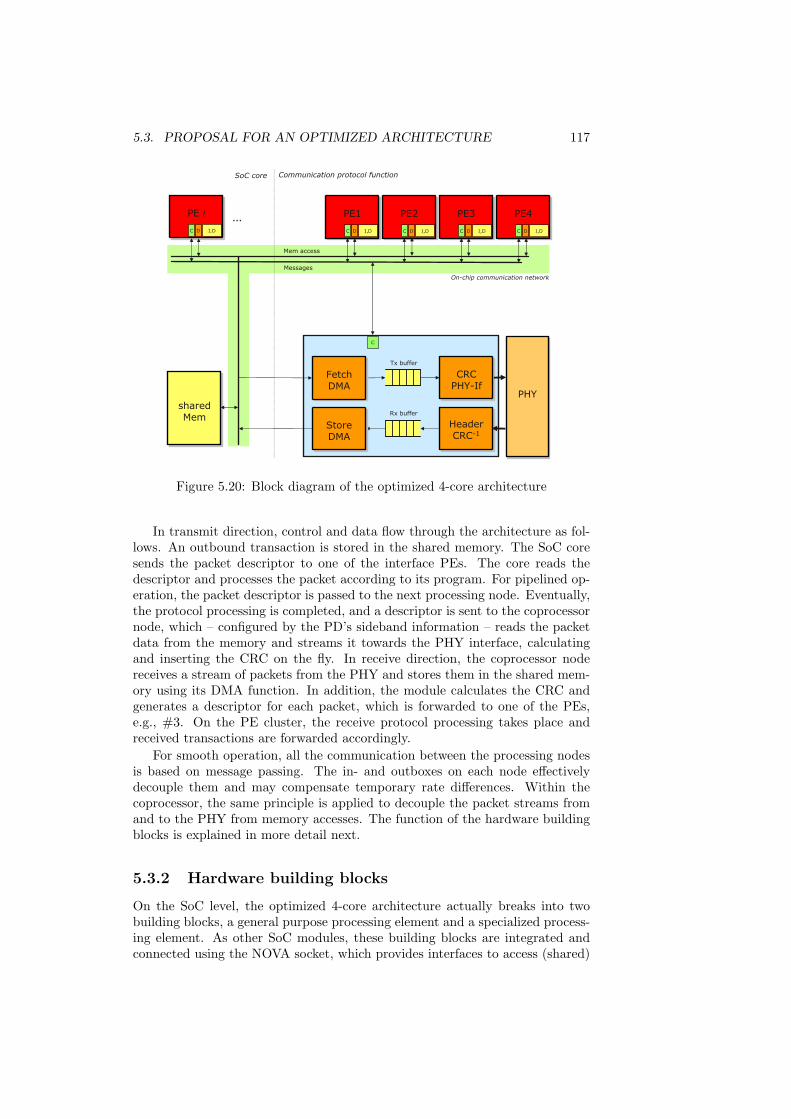
5.3. PROPOSAL FOR AN OPTIMIZED ARCHITECTURE 117
PE2
I,DC D
PE3
I,DC D
PE4
I,DC D
sharedMem
Mem access
Messages
PE1
I,DC D
C
HeaderCRC-1
CRCPHY-If
FetchDMA
StoreDMA
PHY
PE i
I,DC D
Communication protocol functionSoC core
…
On-chip communication network
Tx buffer
Rx buffer
Figure 5.20: Block diagram of the optimized 4-core architecture
In transmit direction, control and data flow through the architecture as fol-lows. An outbound transaction is stored in the shared memory. The SoC coresends the packet descriptor to one of the interface PEs. The core reads thedescriptor and processes the packet according to its program. For pipelined op-eration, the packet descriptor is passed to the next processing node. Eventually,the protocol processing is completed, and a descriptor is sent to the coprocessornode, which – configured by the PD’s sideband information – reads the packetdata from the memory and streams it towards the PHY interface, calculatingand inserting the CRC on the fly. In receive direction, the coprocessor nodereceives a stream of packets from the PHY and stores them in the shared mem-ory using its DMA function. In addition, the module calculates the CRC andgenerates a descriptor for each packet, which is forwarded to one of the PEs,e.g., #3. On the PE cluster, the receive protocol processing takes place andreceived transactions are forwarded accordingly.
For smooth operation, all the communication between the processing nodesis based on message passing. The in- and outboxes on each node effectivelydecouple them and may compensate temporary rate differences. Within thecoprocessor, the same principle is applied to decouple the packet streams fromand to the PHY from memory accesses. The function of the hardware buildingblocks is explained in more detail next.
5.3.2 Hardware building blocks
On the SoC level, the optimized 4-core architecture actually breaks into twobuilding blocks, a general purpose processing element and a specialized process-ing element. As other SoC modules, these building blocks are integrated andconnected using the NOVA socket, which provides interfaces to access (shared)

118 CHAPTER 5. A PROGRAMMABLE INTERFACE ARCHITECTURE
memories and the message passing network.
General-purpose Processing Element
The general purpose PE comprises a 32bit MIPS M4k processing core with localinstruction and data memories. In addition, a memory interface, a tiny DMAfunction, and the message passing interface are integrated into the module.
• M4k core — the core is configured with a dual SRAM interface in order toexecute instruction fetches and load/store accesses in parallel. Its registerset comprises hardware counter and timer registers.
• Local memories — Two single-cycle, single-port SRAMs are used for in-struction and data memory. A small boot rom is mapped into the imemrange. Subsystem functions are mapped into the dmem map and can beaccessed via load/store instructions. Using the redirection feature of thecore, the imem can be accessed via load/stores as well.
• Memory Interface — The memory interface translates the core’s blockingload/store accesses into pipelined split-transaction memory transfers. Thismeans that writes to distant memories can be completed within one cyclewhile reads stall the core until the data becomes available.
• Message Passing Interface — The interface provides multiple (2-4) setsof hardware in- and outboxes for the transfer of messages with differentpriorities. Queue status and data ports can be accessed by the core inaddition to the DMA.
• Tiny DMA — The DMA engine relieves the core from cycle-consumingdata transfers. It may be used a) to transfer bulk data from distant tolocal memory (memcopy), and b) to move messages between local memand message passing interface. To avoid stalls, the DMA has lower prioritythan the core.
Specialized Processing Element
The specialized processing element encapsulates data movers and stream pro-cessing units. In particular, it comprises:
• Fetch DMA — The Fetch DMA receives a packet descriptor, extract packetdescriptor and processing flags, fetches the packet from its storage loca-tion, and streams it towards the transfer fifo. In the process, it insertsa stream header, which contains processing flags and packet length, fordownstream processing units. In addition, it may insert extra data (thepacket header) from the packet descriptor in front of the packet. TheFetch DMA may be configured send a free message after completion ofthe transfer.
• Store DMA — The Store DMA takes a packet from the receive fifo, re-moves the stream header, and stores it the packet memory. For this pur-pose, it uses pointers to free packet memory that are received at its inbox.It may be configured to send a message after completion.

5.3. PROPOSAL FOR AN OPTIMIZED ARCHITECTURE 119
• Receive and transmit buffers — In transmit direction, the buffer shouldstore sufficient amounts of data to avoid underruns during the transferof individual packets. In receive direction, it is used to compensate theprocessing latency for the on-the-fly allocation of packet storage.
• Tx-CRC unit — The CRC unit calculates the CRC for the data stream onthe fly. Its operation can be configured per-packet using the stream header.Options include: type of CRC (polynom, width), bypass/append/overwrite,ignore N initial bytes of the packet. In addition, the module handles theframe alignment (off, pad if lower than N byte, pad to multiple of N byte).If required, precise PHY timing is enforced (send at timestamp).
• Rx-CRC and descriptor generator unit — In receive direction the unitcalculates the CRC while the data is written into the receive buffer. Itsoperation can be selected per-packet using a simple classification of thefirst bytes of the packet. In addition, the unit creates a packet descriptor,stores processing flags (including a timestamp), and copies a configurablenumber of initial bytes (the packet header) into it. To avoid storage over-head, e.g., in case of the PEX link layer packets, the unit can be config-ured not to forward small packets of certain classes which fully fit into thepacket descriptor.
5.3.3 Synthesis results and cost estimation
We implemented a 4PE prototype of the NOVA platform. Its block diagram isshown in Figure 4.11. The system implements MIPS based processing elements,dedicated hardware Ethernet IO modules that are connected to external PHYs,a statistics coprocessor, and a memory interface for shared off-chip SRAM mem-ory. The on-chip communication is based on three OCP buses for system mes-sages, packet descriptors, and memories. In this way, high priority delivery ofsystem messages is assured. Based on the prototype, we evaluate the resourcerequirements of the optimized solution. For this purpose, we will report thesynthesis results for a 90nm ASIC design technology in the following4.
ASIC implementation
The processing element of the prototype shown in Figure 4.10 comprises mostof the intended PE functions. It provides interfaces for memory bus and mes-sage passing network, implements dedicated in- and outboxes for two messagepriorities using single-cycle dual port SRAMs, provides single-port instructionand data memories of 8KB each, boot rom, interrupt controller, and so on.
In the 90nm technology chosen, the processing element achieves a clockfrequency of about 360 MHz. The frequency is limited by the MIPS core itself.The most critical path runs within this IP core. There is almost no variancewith operating conditions (357 MHz, WorstWorst - 361 MHz BestBest). Thearea requirements for the general-purpose PE are listed in Table 5.8. For theconfigured memory sizes, the prototype PE requires .8114 mm2. Most of thearea (.556 mm2, 68%) is occupied by memories. Adding the tiny-DMA function
4To proof the concept, the prototype was also mapped onto a FPGA device (XilinxXC2V6000-4) and successfully demonstrated in a real-world Ethernet LAN setting.

120 CHAPTER 5. A PROGRAMMABLE INTERFACE ARCHITECTURE
requires an extra address decoder and data multiplexer, a 2nd port on eachclient (data memory, MP and mem interfaces), and the DMA logic itself. Thesemodules increase the PE area by about 8%. On the other hand are the transferqueues currently implemented using dedicated dual port memories for each ofthem. Mutually exclusive access in combination with the DMA would enablethe optimization of these queues into one instead of four dual-port memories,which reduces the PE size to .7161 mm2.
Table 5.8: Area requirements of the General Purpose PE.General Purpose PE area memory remarkssub-module [mm2] [%]MIPS core 0.2079 w/o fast mplydata mem 0.1677 99.90 8kB, 1x32x2048 SPinst mem/boot rom 0.1710 97.90 8kB, 1x32x2048 SPmemory interface 0.0047MP Interface 0 0.1356 88.80 512B, 2x32x128 DPMP Interface 1 0.1138 88.60 128B, 2x32x32 DPother logic 0.0107 e.g., intc, data muxtiny-DMA function* 0.0657 4 channelsoptimized MP if** -.1610 100 only 1x DP mem of 512BGP PE total 0.7161 55.18
*) estimated based on IO DMA function, **) area of removed memories
The estimation of the special-purpose PE is based on the encapsulated hard-ware Ethernet IO module of the prototype. This is why we report its footprintfirst. The IO module achieves operating frequencies of 357 (WorstWorst) to 401MHz (BestBest) for the system clock. Table 5.9 lists its area requirements. It,too, is heavily memory-dominated and has roughly the same area footprint asone of the prototype PEs.
Table 5.9: Area footprint of the NOVA Ethernet IO module.Ethernet IO module area memory remarkssub-module [mm2] [%]FE/GbE Mac core 0.5813 93.9Memory Interface 0.0050DMA function 0.0055DMA control/cfg 0.0047Parser 0.0724 83.10 512B, 1x32x128 DPUnparser 0.0662 90.90 512B, 1x32x128 DPMessage Controller 0.1175 85.80 128B, 2x32x32 DPEthernet IO total 0.8480 90.90
The specialized PE reuses most of the IO modules socket functions. Fortruly concurrent operation, its memory interface is duplicated in receive andtransmit direction. Thus, the DMA function is required twice, and the memoryinterface is partially duplicated (x1.5). Parser (packet descriptor generator, rxpath), unparser (packet descriptor interpreter, tx path), message controller, andDMA configuration modules remain the same. The pure CRC calculation logicin hardware is almost negligible, the modules, however, require some pipelinestages similar to a unidirectional memory interface and configuration and stateregisters. The streaming buffers are fifos with dedicated control logic. Due tothe moderate clock frequencies at the PHY layer they are implemented using

5.3. PROPOSAL FOR AN OPTIMIZED ARCHITECTURE 121
single port memories. These estimations all together lead to an area requirementof 0.442 mm2 for the specialized processing element, as Table 5.10 summarizes.
Table 5.10: Area requirements of the specialized PE module.Specialized PE area memory remarkssub-module [mm2] [%]Memory Interface* 0.0075Fetch DMA 0.0055 IO DMA functionStore DMA 0.0055 IO DMA functionDMA control/cfg 0.0047Parser 0.0724 83.10 512B, 1x32x128 DPUnparser 0.0662 90.90 512B, 1x32x128 DPMessage Controller 0.1175 85.80 128B, 2x32x32 DPTx Stream Buffer 0.0580 93.16 2KB, 33x512 SPRx Stream Buffer 0.0900 95.59 4KB, 33x1024 SPTx CRC* 0.0024 0.5x MemIfRx CRC* 0.0097 0.5x MemIf + cfgSpecialized PE total 0.4418 82.69
*) estimated based on prototype modules
In total, the optimized 4-PE architecture requires an area footprint 0.4418 +2.8644 = 3.3062 mm2. The extra area required for the on-chip communicationnetwork was less than 1% (or .0496 mm2) in our prototype implementationwith 8 participating nodes. Considering the smaller number of nodes and theO(N2) complexity, the interconnect area would be approx. 0.0279 mm2 for thearchitecture setup considered.
The overall footprint is dominated by the different instruction, data, andtransfer memories, which require 58% of the area in the given configuration. Anoptimization of the SPE interface queues similar to the GPE could save about5% of the overall area. Sizes of 8kB for code and 8kB for data memory perPE are sufficient to support all protocols except wireless Lan. Increasing thededicated code and data memories by a factor of 2 (4) would increase the overallarea by 26% (76%), see Table 5.11. Section 5.3.4 will discuss other options inmore detail.
Table 5.11: Area requirements for different sizes of code and data memory,absolute in mm2 (and normalized).
data instruction memorymemory 8 kB 16 kB 32kB8 kB 3.3341 (1.00) 3.7621 (1.13) 4,5941 (1.38)16 kB 3.7621 (1.13) 4.1901 (1.26) 5.0221 (1.51)32 kB 4.5941 (1.38) 5.0221 (1.51) 5.8541 (1.76)
5.3.4 Performance & further optimization potential
.The current optimized 4-PE architecture follows the principles of our design
methodology in terms of strict hard and software modularity and high-levelprogrammability. The architecture is flexible in large parts due to the general-

122 CHAPTER 5. A PROGRAMMABLE INTERFACE ARCHITECTURE
purpose PEs and does not comprise any protocol specifics. Even the specializedPE (which is not flexible) is protocol agnostic.
Given the 90nm ASIC system clock frequency of 360 MHz and a messagebus frequency of more than 120 MHz, the 4-PE solution is able handle PCIExpress at full duplex line speed, i.e. 4Gb/s throughput, for packets of 206Bor larger which includes the iMix packet size distribution. Smaller packets canbe handled at lower throughput rates. Minimum size packets of 64 Bytes, forinstance, can be handled up to line rates of 1134 Mb/s. This performance issufficient to support application setups such as a wireless LAN access pointwhich requires aggregated throughput rates in the range of 300 - 600 Mb/s.
However, to support small packets at full speed, further improvement of theperformance is required without increasing the area footprint. Leaving obviousoptions aside such as faster technologies and a full custom PE design (see, e.g.,Intel’s micro-engines, which run at frequencies up to 1.4 GHz) and focusing onimprovements of the platform architecture, several options can be identified:
• Code and data memory footprint — Code and data memory requirementsdepend on application, mapping, and optimization effort. Sizes of 8kBfor code and 8kB for data memory per PE are a reasonable lower boundfor individually assigned memories since they are sufficient to support allprotocols except wireless Lan.
The PCI Express system function, for instance, as implemented by ourmodel requires 11.5kB runtime code for protocol (7.4 kB) and os functions(4.1kB). This means that the 4PE mapping utilizes the code memories by78% since most of the OS function is required per PE. The PEs datamemory of 8kB each is approx. 33% utilized by stack, element configura-tion, and program data. The remaining space serves as heap. The size issufficient for the protocol operation and allows, e.g., to queue more than80 packet descriptors of 64B locally per PE.
The wireless LAN system function exceeds the 8 kB code memory space.In its current implementation, the 802.11a/b/g+e station requires codesizes of up to 22.5 kB (single PE mapping, incl. 6kB os functions, excl.management functions). The dual core mapping which separates TA andDL layer can be squeezed in 2x 16kB of code memory (89% and 96%utilization). The data memory is utilized up to 48%, which leaves spacefor more than 64 packet descriptors of 64B per PE.
The PEs have access to the shared packet memory, which can be used asoverflow storage for code and data. Access to this memory is slow but thetiny-DMA function enables explicit data object and code-page fetching.But even in cases where the fetching time can be hidden by the processingof the core, some software overhead is required due to the DMA handling.
Another option would be a sharing of code memory between PEs to moreflexibly assign and better utilize the memory. Pairwise organized memorybanks, for instance, enable a continuous 16kB code memory for the dualPE wLAN mapping without increasing the overall area footprint. In thiscase (no shared code), there is no performance penalty. However, concur-rent access to truly shared code will have performance penalties due toarbitration effects.

5.4. COSTS OF MODULARITY AND PROGRAMMABILITY 123
• Reduction of scheduling overhead — The analysis in previous sectionsrevealed the OS overhead to be significant, see Sec. 5.1.2, 5.2.4. Thehandling of a timed event, for instance, required 70 cycles (cf. Tab. 5.6)to set the timer, and another 33 cycles to start the associated task chainonce the timer expired. The overall processing budget of a distributedapplication usually is only a few hundred cycles per core. An optimizationof such particular overhead, e.g., by implementation in assembly, couldtherefore improve the performance significantly.
• ASIP based solution — Another option would be to switch to a processingelement with an application-specific instruction set, as discussed in Sec-tion 5.2.3. Due to the speedup of 2.5X, a clock frequency in the rangeof (only) 500 MHz would be required to support 64B PCI Express pack-ets at line speed.5 Using an ASIP, however, means giving up high-levelprogrammability and a loss of platform flexibility for two reasons. First,ASIPs still lack sufficient compiler support. Manual and low-level imple-mentation of the whole application is required to leverage the specializedinstruction set, which is cumbersome and time-consuming, as our ownexperience shows [104]. And second, ASIP PEs increase heterogeneity,so that task-mapping and resource allocation would be restricted to theparticular PEs. A (potentially SoC-wide) mapping to other PEs would re-quire extra implementations of the system function due to the gap betweenthe high-level model and the assembler implementation.
However, switching to an ASIP based solution is a drastic step which wouldspecialize the whole platform towards our application. Before considering thisoption, other optimization potential in application and mapping implementationshould be considered. In the next section, we will therefore investigate theoverhead of modularity in hard- and software, and conduct an experiment whichtailors the SPE logic further.
5.4 Costs of modularity and programmability
Using the NOVA prototype, we quantify the overhead of modularity in hardwareand in software. To derive a lower bound on the requirements of a general-purpose core based solution, we will then look at an implementation which isembedded in a more protocol-specific hardware environment (a ’tailored’ SPE)and does not use the strict modularity of the NOVA platform.
5.4.1 Hardware modularity
The NOVA socket of the prototype interfaces to three on-chip communicationnetworks. Its area is dominated by the transfer queues for packet descriptorsand system messages.
Looking at NOVA’s Ethernet IO module in Figure 5.21, we determine thearea of its socket compared to the embedded Ethernet MAC for the ASIC ver-sion. Depending on the number of queue entries and assuming equally sized
5In combination with the orthogonal optimization of the scheduling overhead, which be-comes more significant for the smaller instruction count on an ASIP, even smaller packetscould be processed at line speed (550MHz for 32B packets).

124 CHAPTER 5. A PROGRAMMABLE INTERFACE ARCHITECTURE
12
34
56
78
910
1112
1
2
34
812
16
25%
28%
31%
34%
37%
40%
43%
46%
Relative
socket
Number of
system messagesNumber of
packet descriptors
Figure 5.21: Relative area overhead of the NOVA Ethernet IO socket.
receive and transmit queues, the socket overhead is between 25% and 46%.Simple SoC bus interfaces without buffering and NoC capabilities require lessarea. A single PLB bus interface without memories, e.g., is only 1% of theMAC area. Buffers included, notably more area is required. Using a singleWishbone interface, the overhead is more than 60% for Opencore’s MAC. Thisindicates that the area for traditional SoC bus interfaces is similarly dominatedby buffering. The required area for the socket is within the range of commonbus interfaces.
The current socket implementation realizes all transfer queues using dedi-cated dual-port SRAM modules. This ensures maximum concurrency and im-plementation flexibility in terms of the different clock domains. But dual-portSRAMs are extremely area expensive, and multiple DPRAMs are more expen-sive than a single one of the aggregated size. Thus, if restrictions in concurrencyor clock frequency ratios can be exploited, much smaller area footprints will beachievable. We applied this consideration to the PE’s area estimation, see thecalculation in Table 5.8.
5.4.2 Software modularity
To determine the runtime overhead of the modular programming environment,we use the CRACC code generator described in Section 4.4 and run the packetprocessing benchmark [174]. This ”out-of-box” version strictly preserves Click’smodularity and object-oriented runtime features such as virtual functions. In asecond step, we de-virtualize functions and resolve push and pull chains stati-cally (CRACC optimized). In Figure 5.22, this is compared to a simple ANSI-Cprogram (straight calls) that calls all functions directly from a central loop,without Click’s function call semantics. The figure reveals that CRACC withstatic optimizations does not impose more overhead than the straight-function-call approach (for a given granularity). There is still a penalty of 30% for thestructured and modular approach compared to a program that inlines all func-

5.4. COSTS OF MODULARITY AND PROGRAMMABILITY 125
tions into a single packet processing loop (all-in-one).
0,00
0,14
0,29
0,43
0,57
0,71
0,86
1,00
1,14
1,28
CRACC
optimizedCRACC
out-of-box
All-in-one
-29%
Straight calls
-28%
Figure 5.22: Overhead of modular software.
On the other hand, a fine-granular partitioning of the application into smallelements is helpful for multi-processor mapping, as we observed in Section 5.2.4.Thus, a post-mapping optimization step, which groups task chains into ’super’-elements, would potentially be beneficial for the execution performance.
5.4.3 A less modular architecture experiment
To derive a lower bound on the requirements of an implementation approachbased on general-purpose cores, we now consider an architecture which does notfollow the strict modularity and generality paradigms of the NOVA platform.The system implements the GbE protocol in full duplex mode, which is the leastcomplex protocol version in our collection.
Hardware Architecture
The architecture comprises a processor which is directly connected to the func-tions of the specialized PE via buffered communication links. The boundariesbetween GPE and SPE blur, see Figure 5.23.
The former SPE functions, sender and receiver, are here tailored to the pro-cessing specifics of the GbE protocol. Like the functions described in Sec. 5.3.2,these modules handle the CRC processing. The protocol timing function of thesender is limited to a counter for the interframe and pause intervals. Unlikethe modules of the SPE, the (protocol-specific) framer and deframer functionsare included here to enable a standard compliant GMII interface to the PHY.Sender, receiver, and transfer buffer interface with the interrupt controller (ITC)of the core, which is used to notify the core about state changes. For this pur-pose, a queue is provided that holds cause and context data of events. For theexperiment, we are not interested in the SoC interface to the remaining sys-tem. This is why we keep it separated. An interface comparable to the oneof the NOVA system encapsulates the packet fetch and store functions whichautonomously transfer the packet data.

126 CHAPTER 5. A PROGRAMMABLE INTERFACE ARCHITECTURE
I,D
shared
Mem
SoCInterface
Receiver
SenderFetch
DMA
StoreDMA
PHY
PE i
I,DC D
Communication protocol functionSoC core
…
On-chipcommunicationnetwork/bus
core
ITC
(1) (2) (3)(4) (5)
Figure 5.23: Specialized GbE SoftMac architecture.
As soon as a packet is ready for transmission, the core is notified by aninterrupt via the ITC module. The software reads cause and packet length fromcommunication link #1 and starts the transmit processing, which gathers theinformation required for the operation of the sender module. As soon as itsprocessing is complete, this data is written into communication link #5. Thesender reads the information into its register context and starts the transmissionof the frame as configured.
Incoming packets are handled by the receiver, which stores them in wordsinto the receive buffer. In the process, the packet header together with theprocessing status is copied into communication link #2. As soon as the packetreception is completed, an interrupt is generated, and the processor core isnotified. The software uses the provided information to process the packet. Italso calculates the true packet len, which is used by the sender to update the(alternating) write pointers of the receive buffer (link #4).
If the buffer runs full, pause frames are generated by the software and writteninto link #3, from where they are transmitted as other tx frames. Receivedpause frames are forwarded to the core (#2), which deletes them from thereceive buffer and configures the sender to pause for the specified interval.
Protocol Software
The software for the GbE protocol is implemented as an interrupt routine ofthe processor core. Following the insights of the previous section, the programimplements the full protocol function as single loop body without function callsand sub programs. Communication accesses are included directly as inline as-sembler instructions. The rest of the program is C code.
The performance critical execution path of the software is the reception ofa data frame, its validation, and receive buffer update, which is followed by thegeneration of a pause frame.

5.4. COSTS OF MODULARITY AND PROGRAMMABILITY 127
Implementation results
As before, the architecture is synthesized for an Xilinx Virtex-II FPGA anda 90nm Infineon semi-custom technology. For efficiency reasons, the FPGAimplementation deploys the Xilinx Microblaze CPU as processing core and usesthe fast-simplex links for the communication. The Microblaze is optimized forthe FPGA implementation which results, compared to the MIPS core, in muchhigher operating frequencies (100 vs. 25MHz) and fewer slices.
Without consideration of the required context switch, the execution of thecritical path requires 97 instructions which translate into 129 cycles on theMicroblaze. Taking into account the overhead for routine call (6+6 cycles)and context saves/restores (14x4 cycles) a total of 197 cycles is required. Thismeans that full line speed for minimum size packets could be achieved with clockfrequencies between 210 (no context save required) and 294 MHz (full contextsave required). The full program requires less than 2kB code and data memory(1132 Byte code memory and about 200B data memory).
Table 5.12 reports the ASIC area requirements for the GbE SoftMac. Thearea depends on the memory configuration. The smallest area has the memoryconfiguration with a single 2kB memory for both, code and data. Comparedto a NOVA implementation with a single general-purpose PE and similar mem-ory configuration, shown in the right column, the GbE SoftMac has an areaadvantage of 16%.
Table 5.12: Area requirements in mm2 for the processor-based GbE variant withdifferent memory configurations in comparison to the NOVA implementation.
sub-module GbE SoftMac NOVA SoftMacNeumann Havard Havard Havard
MIPS core 0.2079 0.2079 0.2079 GPPE 0.7161data mem 0.0982 0.0630 0.1710 -.1190inst mem/boot rom 0.0487 0.1677 -.1080
Rx buffer fifo 0.0900 0.0900 0.0900 sPE 0.4418Tx buffer fifo 0.0900 0.0900 0.0900Rx len fifo 0.0193 0.0193 0.0193Tx len fifo 0.0237 0.0237 0.0237Communication links 0.0215 0.0215 0.0215Hardware logic* 0.0595 0.0595 0.0595
SoC interface** 0.1561 0.1561 0.1561total (minimal mem) 0.7626 0.7762 0.9309total (regular mem) 1.0032 1.1579
*) includes FIFO control logic. **) 3xMemIf, 2xDMA, SysMsgIf (Tab. 5.10).
The software implementation of the tailored GbE MAC is substantially bet-ter in both, code size and runtime performance, than the CRACC-generatedversion. Including operating system functions, the model generated by CRACChas a runtime code size of approx. 7 kB and would require 572 cycles for theexecution of the critical path (on the MIPS PE). These differences have severalcauses:
• Overhead of modularity — The GbE implementation essentially is a singlefunction which comprises all necessary operations. No subroutines what-

128 CHAPTER 5. A PROGRAMMABLE INTERFACE ARCHITECTURE
soever are required. The Click model on the other hand has at least tenelements in the critical path. Considering the insights on the overhead ofmodularity from Section 5.4.2, this alone would account for approx. 152 -170 cycles.
• Comprehensive Click elements vs. essential functions — Most Click/Craccelements comprise code that makes them more robust, better interchange-able, or independent. Elements usually can be configured for several usecases or are implemented for the general case. The Classify element, forinstance, is only used to filter pause frames (particular ethertype value,i.e., a comparison of two bytes) but can easily cope with large sets of clas-sification rules. The GbE SoftMac implements the essential function in afew lines.
• Shared state and packet descriptor handling — The Click/Cracc imple-mentation holds processing state in structures (either in the element or inthe packet descriptor) that are stored in main memory. To share state,elements have to exchange it explicitly, i.e., it must be copied in memory.This requires extra code and processing cycles compared to the GbE im-plementation, which holds all processing state in local variables that aremapped to registers.
• Dynamic scheduling, different IO functions, other platform overhead —The NOVA scheduler enables dynamic task scheduling and handling whilethe GbE Mac relies on a statically scheduled implementation. NOVApacket descriptors furthermore are 64 Bytes and must be moved betweenmemory and transfer queues (10+10 cycles). The GbE Mac reads onlythose 20 Bytes that are actually required by the protocol (5 cycles). Thetransfer of the pause frame costs only seven cycles. Furthermore, theNOVA platform provides APIs for timers, memory access and manage-ment, message passing, and packet handling, which are all avoided by thetuned GbE implementation.
Overall, the optimization potential of a software protocol implementationthat is generated by CRACC is large. For the Gigabit Ethernet protocol, weobserve a potential runtime improvement by a factor of 2.9X for the manuallytuned (but still in C implemented) version of the protocol, which avoids theClick/CRACC programming model and platform abstractions. However, sincethe GbE protocol is the least complex function of our protocols and, therefore,exposes the platform overhead the most, we expect the potential for optimiza-tions to be smaller for the other protocols.
The tailored hardware implementation of the protocol can not improve therequired area much. For the GbE implementation we expect an area advantageof only 16% compared to a single-core NOVA platform. This is not surprisingsince, in any case, the implementation is dominated by memories, communi-cation interfaces, and the processor. The actual protocol-specific logic is onlya fraction of the area. The NOVA general-purpose implementation, however,scales better with the number and the type of the supported protocol functions.

5.5. RELATED WORK 129
5.5 Related work
Work related to our implementation of packet-oriented communication inter-faces based on a programmable platform can be found in in three domains: I)modular and programmable platform architectures, II) existing Flexibility incommunication interfaces, III) other flexible IO interface implementations.
5.5.1 Modular platform architectures
Programmable platforms, according to [56] p.15, are the next design discontinu-ity. They promise higher design productivity, easier verification, and predictableimplementation results. Rather than the design through assembly of individ-ual IP blocks, programmable platforms provide hard- and software templatesbased on a family of processors that can be tailored quickly to optimize costs,efficiency, energy consumption, and flexibility. Key features of a programmableplatform thusly are modularity, simplicity, and scalability.
• Modularity in hard- and software aspects enables the system-level designerto quickly customize the platform to the specifics of an application withoutbreaking the programming model. It also leads to clearer design choiceswhen building complex systems [92]. In addition, it eases the extension ofthe platform’s modules by providing a set of well defined interfaces.
• Simplicity improves usability and eases the use of a platform. Insteadof, e.g., centering a platform around a particular (feature-rich) processorarchitecture and bus protocol, a platform should keep concerns separated.The platform should be core- and communication-protocol agnostic. Con-sequently, an existing bus interface should be replaced with another onerather than with a wrapper for the existing interface. In addition, thismeans that the complexity of modules such as a standard processor coreshould be carefully reduced as needed, e.g., by removing MMU, caches,and certain functional units.
• A scalable platform is able to accommodate a wide range of I/O interfacesand processing elements for handling different processing and communi-cation requirements without breaking the programming model or forcingthe applications to be re-written for each platform instance.
A survey of the broad variety of packet processor architectures and platformscan, e.g., be found in [177, 205]. Most of these architectures have been optimizedfor high-performance. But other platform aspects such as the programmabilityand modularity have often been neglected. Further examples of commercialplatform solutions for wireless and multimedia domains are Nomadik from STMicroelectronics [12], and Philips Nexperia [44]. As mentioned before, thesearchitectures are centered around particular cores and bus protocols.
There are a few platforms [145, 116] which follow similar approaches as theNOVA platform in terms of programmability and message-passing communica-tion:
• StepNP [145] is probably the processor platform which is most closelyrelated to NOVA and CRACC (see the discussion in Section 4.2.2 on itsprogramming model and exploration method). Both platforms support

130 CHAPTER 5. A PROGRAMMABLE INTERFACE ARCHITECTURE
the range from general-purpose over application-specific to hardwired (co-) processing nodes which can be connected following the network-on-chipparadigm.
Similar to NOVA, the StepNP platform provides support for message-passing in hardware. In addition (and unlike NOVA), it implements cen-tralized hardware accelerators for dynamic task allocation, scheduling, andsynchronization, as it is beneficial for SMP and SMT programming mod-els [146], which are not in the focus of the NOVA hardware implementa-tion. However, StepNP seems to always map processor-memory commu-nication onto the same latency-intense on-chip communication networkand therefore requires hardware multi-threading to hide memory accesslatencies in any case [146].
NOVA supports both, simple pipelined memory buses (split-transaction,ld/st access) as well as memories which can be accessed via message-passing primitives (rd/wr, rd response). Contrary to StepNP, NOVA doesnot depend on hardware multi-threading and therefore does not limit theapplication concurrency. The run-to-completion and encapsulated-statesemantics of the Click model-of-computation naturally support softwaretasks-switches with low overhead.
Judging from the case studies in [146], StepNP’s platform overhead issomewhat comparable to NOVA. StepNP implements only small MPItransfer buffers of 512b (16 words) while NOVA implements at least 512B(128 words). Yet, for a fair comparison, StepNP’s extra hardware contextsmust be taken into account as well (between 112 and 224 words), sincethey are used to store the processing context for the individual transac-tion. The reported software overhead for the handling of messages as wellas the round trip latency is similar to NOVA’s system messages. Theextra overhead of 10-12 instructions on the receiver (’server-side’) to in-voke the requested method seems quite efficient but may be too optimisticin peer-to-peer communication settings. NOVA’s current implementationdepends on the number of (dynamically registered) ’listeners’ and requiresbetween 19 and 47 instructions for our application mappings. Code anddata memory footprints for OS-like functions are not reported.
• Tensilica’s Xtensa [116, 121] is a configurable processor which (apart fromthe usual bus interface) provides direct support for communication withdata-flow semantics. The processor template [64] allows the addition ofarbitrary-width IO ports, which can be used, e.g., for queued and directregister-to-register communication between two processors. This featureallows embedding the processor directly in the data flow as data can beconsumed and generated using in- and outports.
However, use cases such as the packet descriptor passing of Click cannot leverage this feature well. Packet descriptors must be stored in localmemory but not necessarily require processing of all data words. A flow-through approach would therefore impose unnecessary load on the core,see Section 5.2.2. Extra hardware, similar to NOVA’s tiny-DMA functionwould be the consequence.
We kept the NOVA platform core-agnostic by using a memory-mappedsubsystem which provides access to local peripherals via load/store in-
5.5. RELATED WORK 131
structions. This way, arbitrary cores (including the Xtensa) can be sup-ported. The exploitation of core specific-features such as specialized low-latency IO ports would be an interesting optimization of a particularNOVA-PE.
We explored the benefits of a flow-through setting using the Xilinx Mi-croblaze with its Fast-Simplex-Links in Section 5.4.3. The Click/Craccprogramming model would be portable to a Xtensa PE. Tensilica itselfdoes not provide a multiprocessor programming model.
NOVA postulates strict modularity in hard- and software as a key concept.This is in tune with the goals and efforts of initiatives such as the VSI alliancewhich has a broad scope and aims at virtual IP sockets to enable reuse andintegration [117]. The NOVA socket follows the widely used OCP specifica-tion6, which is more focused and better suited to our needs. The definition ofmeaningful software interfaces and programming abstractions is still an area oflively research, see, e.g., [115, 208, 179] and the references therein. The Multi-core Association is aimed at the definition of a MP communication API [118].Our implementation of the NOVA OS functions was driven by the requirementsof the Click model-of-computation. Wherever possible, well known and effec-tive techniques were used, e.g., for memory management or message-passingcommunication.
5.5.2 Flexible interface implementations
Already the analysis of contemporary SoCs in Chapter 2 revealed differentimplementation techniques to provide flexibility in communication interfaces.Apart from the physical multiplexing of individual IP modules [3] and the em-bedding of reconfigurable logic into the SoC [61, 120], we found few (rare) pro-grammable approaches for IO interfaces:
• Use of specialized co-processors — At the high-end, some systems deployspecialized co-processing elements that are micro-programmable for a welldefined set of network interfaces (ATM, Ethernet). The Motorola C-5 [51],for instance, uses two Serial Data Processors (one for send, one for receive)in each of its 16 channel processors. They provide a number of individuallow level tasks for the network interface such as bit field extraction andCRC calculation.
• Fully in software — For low performance interfaces, we find implementa-tions solely provided in software running on processors. Such a solutionprovides full flexibility with only minimal area consumption for the inter-face. In case of Ubicom [47], the multi-threaded processor with specificinstruction set requires a specialized operating system to fulfill the real-time requirements of the interfaces. Per software IO interface, a dedicatedhardware real-time thread is required (up to six are concurrently possible),which is scheduled deterministically (TDMA). The remaining threads areused by the application software and are scheduled round-robin. Althougha promising approach in terms of full programmability, the solution can
6www.ocpip.org

132 CHAPTER 5. A PROGRAMMABLE INTERFACE ARCHITECTURE
only support limited bandwidth [47, 62]. The implementation of a stan-dard PCI interface, which is supposed to run at 33 or 66 MHz, achieves abus frequency of 10 MHz.
Certainly, one reason for this serious limitation is the flow-through ap-proach of the architecture. The processor must move every data wordfrom and to the interfaces, which leads to extremely tight budgets of afew cycles per word. The Ubicom approach is therefore not feasible forour high-throughput communication interfaces.
To the best of our knowledge, there have been no successful attempts toimplement PCI Express, Hypertransport, RapidIO, or Gigabit Ethernet similarto us on a programmable architecture. Only the work in [80] describes the ideaof a PEX device in which the hardware is assisted by a microcontroller. Thecontroller runs a realtime OS and apparently handles link layer packets includingthe replay buffer. However, neither protocol performance nor implementationresults are reported.
Mature work related to software implementations of our protocols can befound only for wireless Lan, probably fostered by the relatively low bandwidthrequirements, the proximity to software-defined-radio platforms (which requireMAC functionality for their already flexible PHY radios), and the availability ofa 802.11a Mac reference implemented in SDL. In the following, we will thereforeexamine a selection of these wLAN Mac implementations and discuss them withrespect to their flexibility in three broad categories in comparison with ourapproach:
• The usual hardware/software function split — Most of the published pro-tocol implementations follow a function split, which implements time crit-ical and compute intense aspects such as channel access timing (DCF),control frame processing, CRC calculation, and address validation in hard-ware close to the PHY interface - the ’low Mac’. Other protocol functionssuch as management and queueing, which are neither compute-intense norperformance critical, are kept in software – the ’high Mac’ [65, 165, 216,140]. Across the implementations, this function split is relatively fixed.
– In [65], Hannikainen et al., describe the implementation of a wLANMAC protocol starting from SDL. The resulting system maps themost critical functions into hardware (channel timing, encryption,CRC), the rest is software on a DSP processor. The reported memorysizes of 490kB code, 61kB data, and 100kB dynamic memory includefunctions that are usually considered for running on a host processoras part of the OS’ device drivers such as user interfaces, networkmanagement, rate selection, and statistics.
– In [165], some data is provided on the performance of different oper-ating systems in terms of context switching time and code and datamemory footprints. Due to the considerable overhead, the authorsavoid the use of any OS. Instead, they implement the high Mac func-tion in two routines (rx, tx) as part of the interrupt handler on theDSP processor of their prototyping system. After some code opti-mizations, a throughput rate of 54Mb/s is reported for larger framesthat are fragmented into 256Byte segments.

5.5. RELATED WORK 133
The best OS in the comparison is ThreadX, which is reported torequire 15kB code and 2kB RAM. The NOVA runtime configurationfor wLAN requires approx. 6kB code and a few hundred bytes RAMfor the OS functions. Context switching, i.e., swapping the registercontext is reported to require 100 cycles for ThreadX. The NOVAsystem does not require this overhead due to its run-to-completionmodel-of-computation.
– Panic et al. [140] present synthesis results for a MIPS4k based systemwhich follows the usual function split. The implementation suffersfrom deficiencies such as the lack of memories for the target standard-cell technology. Without the memories7, the hardware accelerator is5/6th of the area of the MIPS processor. This seems quite large.Without its memories, the NOVA SPE would be less than 50% of aMIPS core.
• Modifications of the MAC function — Although for diverse reasons, aconsiderable fraction of the related work tries to change the MAC function,see [43, 75, 209, 210] and the references therein. All this work would benefitfrom a platform which enables easy changes on the MAC function.
– Doerr et al. [43] describe the SoftMac approach, which tries to disablemost of the wireless MAC function found in commodity hardware.This enables a framework (MultiMac) that supports coexisting soft-ware Macs with different functions. Interestingly, an interface toClick is provided to ease the protocol development. So far, the solu-tion would not achieve wLAN timing in software.
– The work by Wu et al. [209, 210] circumvents changes of the MACitself by describing a layer on top of regular 802.11 a/b/g MACs. Thesolution provides quality-of-service features to support Voice-over-IPin wireless multi-hop networks. For this purpose, the low-level devicedriver on the host processor is changed and extended. According tothe authors and their discussion of related work do others depend onchanges of the DCF function or require 11e capable MAC functionsfor the same purpose.
– Addressing the need for changeable MAC functions from a differentangle, Hunter et al. [75] present a FPGA based prototyping platform,which (to some extend) allows modifications of the low Mac function.
• Fully flexible implementations — Few papers actually map the full MACfunction onto a processor core and analyze the achievable performance.Similar to our fully flexible approach, the authors use their findings asstarting points for further optimizations either of the processor or its hard-ware environment.
– To motivate their later implementation of the usual much less flexiblefunction split, Panic et al. ([140], see above), start with a SDL sim-ulation model of the MAC. They use the model to generate C-codewhich is profiled on a MIPS M4k instruction set simulator. Since
7The memory for the low Mac is synthesized from standard cells and reported separately.
134 CHAPTER 5. A PROGRAMMABLE INTERFACE ARCHITECTURE
the execution requires some sort of SDL runtime environment caus-ing heavy overhead, the generated code is manually optimized. Afteroptimizations, the authors report a clock frequency requirement of1000 MHz for a single-core 11a MAC (12Mb/s) fully implemented insoftware. This seems somewhat in the range of our own initial pro-filing results (4 GHz for 54Mb/s, cf. Sec. 5.1.3). However, a detailedanalysis (which may have revealed the critical and only dependencyon the monolithic encryption function) is not performed. Furtherquantitative insights that would support the usual function split oftheir resulting system are not provided.
– Shone et al. [184] implement a wLAN MAC fully in software on aPowerPC running at 400MHz. The processor runs VxWorks as oper-ating system and is part of a software-defined-radio prototype, whichcomprises several physical modules that are connected by a VME bus.The implemented Mac function is 802.11a. Features such as security(WEP) and RTS/CTS control frame handling are not implemented.For this system setup, three severe difficulties are reported in meet-ing the realtime requirements of the wLAN protocol (i.e., the SIFSdeadline of 16µs). First, the inter-module bus connection is too slow.It requires already 40µs to transmit a maximum Ethernet frame be-tween PHY and MAC module. Second, interrupt response (3µs) andcontext switching (200µs) times of the OS are too large. And third,the clock of the CPU board had a jitter of 399 µs. As a consequence,the protocol deadline had to be extended by at least a factor of tento make the system operational.Due to a single-chip implementation, our NOVA solution avoids theissues of clock jitter and extra transfer times. In addition, NOVA exe-cutes the Mac protocol processing concurrently to the packet transferwhich shortens the critical path. NOVA’s event handling and taskactivation latencies are in the order of less than .5µs.
– Other work [74, 84] maps a Mac onto an ARM processor to study theimpact of micro-architectural changes. In [74] the benefits of multi-threading, extra functional units, and a reduced instruction set, arereported in comparison to the original configuration. Overall a per-formance improvement by a factor of two is reported using a 3-threadtwo-issue configuration. Indications of the absolute performance arenot provided. The work in [84], which provides a profile of the ex-ecuted instructions, argues in favor of a dynamically configurableinstruction set to increase the utilization of the micro-architecture.We explored the performance potential of an application-specific pro-cessor with reduced instruction set in Section 5.2.3 and observed rel-ative improvements in the same order of magnitude (factor of 2.5)for the given implementation.
5.5.3 Complexity of individual protocol implementations
This section seeks to gather publically available data on the implementation costsof individual communication interfaces in hardware, and (if possible) comparestheir function to our implementations.

5.5. RELATED WORK 135
In general, it is difficult to find published data on the costs of particularimplementations and its breakdown to individual functions. The most compre-hensive set of data could be collected for Xilinx IP cores, which we synthesizedon a Virtex-II FPGA. Each of the Xlinix cores basically implements the leastfunctionality to comply with the standard, i.e. optional features were disabled.SoC interface functions such as DMA engines and bus interfaces are not in-cluded. Table 5.13 summarizes the results. Unfortunately, a detailed functionalbreakdown of the required resources was not possible for PEX, HT, and Ra-pidIO due to the lack of analyzable source code. A wireless Lan Mac hardwaremodule is not available. The related work on wLAN MACs implementationsdiscussed in the previous section implementations did not provide conclusivedata on hardware resource requirements either.
Table 5.13: Minimal resource requirements of individual communication inter-faces based on Xilinx IP cores on a Virtex-II FPGA.
Module Included Function Slices BlockRAM
Gigabit Ethernet (GbE) PHY, DLL, TA 1400 4x2= 8kBHypertransport (HT) PHY, DLL, TA 3990 20x2=40kBRapidIO (RIO) PHY, DLL, TA 5277 9x2=18kBPCI Express (PEX) PHY, DLL, TA 6719 16x2=32kB
Microblaze (Mbz) CPU, OPB-If, 2xLMB 1020 >2x2= 4kB
References: HT [211], RIO [215, 212], PEX [214], GbE [213]
As a point of reference, the resource requirements of an Microblaze processorcore with a minimal subsystem comprising an OPB bus interface, and code anddata memory interfaces (local memory bus - LMB), are provided.
• PCI Express and RapidIO — In addition to the functionality modeledin Click, the Xilinx cores [214, 215, 212] include initialization and powermanagement (PEX) functions as well as maintenance and status tracking.Also, configuration and management modules are included, which handlecommunication with the other modules and provide an interface to theuser-level.
Other implementations of PCI Express endpoints:
– Based on designs by Infineon Technologies, an area of 1.48mm2 for arudimentary device without PHY functions can be estimated. Thisincludes an AHB slave as SoC bus interface and support for onevirtual channel. The transaction size is limited to the burst size ofthe bus (max. 64B) to avoid segmentation and reassembly. DMAand reordering features are not included.If three channels are included (as in our model), the area increasesto 2.09mm2 due to larger memory. Without the SoC interface andusing the ratio published in [30] (see below) to estimate the requiredslices, this would roughly translate into 9000 slices.
• Hypertransport — Similar to our HT Click model, the Xlinix IP core [211]used in Table 5.13 implements an revision of the standard which does notinclude the packet-based mode with retransmissions (see the discussion

136 CHAPTER 5. A PROGRAMMABLE INTERFACE ARCHITECTURE
of [30] below). For the same revision, another commercial HT endpoint isavailable, which requires 2.7x as many slices (10750) [50] but has a widerdata path (128b) and allows higher throughput. In both cases, a SoCsocket interface is not included.Other work on HT implementations includes [68, 30]:
– Hasan et al. [68] implement a network-on-chip based on the HT pro-tocol which may homogenize the overall communication structure ofsystems. Their ’HT light’ tunnel implementation is discussed in ref-erence to HT. However, in terms of implementation complexity foran HT node, no comprehensive picture is provided. Only two aspectsare mentioned: 1) a buffer memory requirement of approx. 9.4kB forsuch a node, and 2) a complexity estimate of 9.25k gates only for theCRC calculation logic.
– Castonguay and Savaria [30] implement a protocol compliant HT tun-nel (device with forwarding function). The system requires approx.132k gates or 18.1k LUTs. In addition, a total of 5.4kB memoriesfor data (3kB), command (400B), retry buffer (1kB), and user databuffer (1kB) is used. According to earlier work by the authors [29],this memory size is sufficient to store one packet per flow. The per-module breakdown identifies flow control and retry functions to con-tribute most to the system complexity (52% of the area). Since atunnel requires two interfaces, and all modules except user interfaceand configuration and status are instantiated twice, a ballpark fig-ure for the complexity of a single interface can be estimated as 73kgates without memories. Given the reported size on a Virtex-II ProFPGA, this would translate into approximately 73/132 x 18.1 x 1/2= 5000 slices and is in the range of the other implementations.
• Gigabit Ethernet — The area breakdown for a complete Gigabit Ether-net Mac controller including an exemplarily interface to a 64bit PLB isspecified in Table 5.14. In addition to the data buffers (4kB each), extraqueues are implemented, which store the length of each packet. The datais based on our own implementation which was verified against the XilinxIP core.
Table 5.14: Resource breakdown of a GbE hardware controller.Module/Function Slices BlockRAM
PHY layer ∼480MAC (DLL/TA) 575Tx Buffer (data+len) 201 3x2=6kBRx Buffer (data+len) 207 3x2=6kBPLB bus interface (64b) ∼500
1960 6x2=12kB
5.6 Chapter summary and discussion
This chapter investigated the feasibility of a programmable solution for packet-oriented communication interfaces, which is:

5.6. CHAPTER SUMMARY AND DISCUSSION 137
• composable from a modular platform that can be scaled to the interfacespecifics of a System-on-chip without breaking the overall constructionparadigms and is
• easily programmable, following a high-level programming model that isnatural and productive for the application domain.
NOVA platform
For this purpose, we have developed NOVA, the Network-Optimized-VersatileArchitecture platform. NOVA supports the exploration of a programmable andmodular solution by applying four design principals:
• Modularity — Generalized hardware sockets are used so that interfacingto processing resources can be decoupled from interfacing to the inter-connect infrastructure. Similarly, our software framework is organized inexchangeable components that represent computational kernels.
• Simplicity — To tackle the complexity of today’s SoC’s, NOVA is buildfrom basic hard- and software modules, which: keep concerns separated,do not make assumptions on each other’s function, and are designed fora particular purpose. Instead of extending a module to serve multiplepurposes, we prefer to provide another module wherever possible. Incombination with the modularity principal this helps to avoid the usualperformance-killing fallacy of complex hard- and software IPs wrapped inmultiple layers of abstraction circuitry for configuration and interfacing.
• Scalability — NOVA supports a wide range of I/O interfaces and process-ing elements to handle different application requirements without break-ing the programming model. The NOVA socket and message format allowthe integration of traditional shared buses [164], as well as better scalableNetwork-on-Chip (NoC) techniques [18] and enable arbitrary numbers ofprocessing nodes.
• Customizability — NOVA provides design points for customization if themost flexible solution does not meet design criteria. Coprocessors, forinstance, either tightly or loosely coupled, can be used without breakingthe representation of the application.
Guided by these design principles, the NOVA platform implements the state-of-art in concurrent SoC platforms while avoiding some of the fallacies of otherapproaches as discussed in Section 5.5. Our analysis of the overhead introducedby modularity in hard- and software in Section 5.4 further revealed costs interms of on-chip area and execution performance that are also comparable toexisting techniques. We have published our findings in [166].
Design space exploration
Using NOVA and our code generators, we explored the performance / areatradeoffs involved into the implementation of a programmable interface solu-tion. Following our application-driven methodology, we started with the profil-ing of the communication interfaces mapped on a single-core architecture andobserved:

138 CHAPTER 5. A PROGRAMMABLE INTERFACE ARCHITECTURE
• Per-packet protocol processing — Most protocol processing happens per-packet and is only based on the packet’s context/header.
• Cycle-consuming payload processing — Those rare functions that actuallytouch the whole packet, such as CRC calculation and encryption, are themost cycle consuming functions.
• Non-deterministic processing times — Large monolithic elements in com-bination with Click’s run-to-completion model-of-computation make it im-possible to meet hard real-time deadlines as required,e.g., for wireless Lan.
The performance of the single-core architecture is not sufficient as the anal-ysis revealed. Especially for small packets, multi-gigahertz clock frequencieswould be required to meet either the throughput requirements (PCI Express)or the tight deadlines for packet reception and response generation (wirelessLan).Next, we explored several axes of the platform design space and studied theirimpact on the system’s performance using our SystemClick framework and thecollected profiling data:
• Core type — To compare different embedded RSIC cores and their compil-ers, we profiled a packet processing benchmark implemented in CRACC ona representative set of synthesizable embedded 32bit processors. Althoughthe general purpose cores achieved a somewhat comparable performancein terms of packet throughput for our benchmark, we found the MIPSM4k to have the best performance-area trade-off. The application-specificcore included in the comparison were not able to perform well, due toinsufficiencies in its high-level programmability.
• Hardware accelerators — By deploying hardware accelerators for the pay-load processing functions CRC and data transfer (DMA), the processingperformance can be improved by factors between 2.8 (min) and 114 (max)for PCI Express, the most complex high-throughput protocol. In case ofwLAN, the slowest of our protocols, up to a factor of 1.2 was observed.
Another candidate for hardware acceleration would be the WEP functionwhich is used by wireless Lan and consumes the vast majority of its cycles.However, the overall performance requirement of wLAN is moderate sothat WEP could remain in software, saving protocol-specific area.
• Application-specific instruction set processor — By deploying an ASIPinstead of a general purpose processing core, performance improvementsby a factor of 2.53 can be expected looking at the critical path of PCIExpress.
Using an ASIP, however, means giving up high-level programmability anda loss of platform flexibility. Our experience from network processing [104]and our ASIP design experiments with the Tipi framework publishedin [128, 168] show that ASIPs still lack mature compiler technology. Seealso the performance of the ASIP and its compiler in our core type explo-ration. Programming them in assembler is the consequence as we did forthe static analysis in Section 5.2.3.
5.6. CHAPTER SUMMARY AND DISCUSSION 139
ASIP PEs increase the platform’s heterogeneity and limit mapping andresource allocation since the whole application must be re-implemented inassembly to leverage the specialized instruction set. Although supportedby the library based approach of Click/Cracc this would lead to multiplesources for an element due to the gap between high-level and assemblyimplementation.
• Multiple processing elements — Exploiting concurrency in the application,we investigated mappings of up to seven cores.
The analysis revealed a four-core mapping to be a reasonable choice be-tween speedup and number of cores for the high-throughput interfaces. Afour-core mapping of a duplex PCI Express link achieves a speedup of 1.85.The considered higher core mappings would only marginally improve thespeedup (5:2.19, 6:2.34, 7:2.73) due to the given application granularityand implementation.
The realtime requirements of the wireless Lan protocols can be met using adual-core mapping, which separates real-time critical and compute-intenselong running functions from each other.
• Communication topology — To study the communication requirements,we assumed all processing nodes to be connected by a single write-onlybus which is used to exchange packet descriptor messages. Based on Sys-temClick several hundred design points were evaluated that vary in busspeed and size of the in- and outboxes.
We found a single bus to be sufficient in any case if it runs at 30% or moreof the PE’s clock frequency. Only those cases in which in- and outboxeshave only a single entry per link show slight performance degradation(-1%).
With increasing bus utilization, i.e. for lower bus speeds, the size ofthe transfer queues becomes more important for compensating the non-availability of the bus. In the case of a 20% speed, sizes of 3 (out) to 4 (in)entries per link are necessary to achieve the full performance. If the busspeed becomes too low (10%), the available communication bandwidth isno longer sufficient. In this case, queues do not matter. They are alwaysfull and stall the processing pipeline.
4PE+SPE instance of the NOVA platform
Based on these insights, we propose a NOVA platform instance with four general-purpose PEs for the protocol processing software and a specialized hardwareprocessing element which comprises flow-through accelerators for the payloadprocessing and handles the PHY interface. The architecture is protocol agnos-tic. Only the CRC function, which is part of the SPE, must implement thesuperset of all used polynomials. Leveraging the implementation of the NOVAprototype, we conclude on the platform instance:
• For the chosen 90nm ASIC technology, the architecture runs at a systemclock frequency of 360 MHz and requires an area of 3.3 mm2. 58% of thearea are memories. The modules are decoupled and run asynchronously.
140 CHAPTER 5. A PROGRAMMABLE INTERFACE ARCHITECTURE
• The system can handle PCI Express at full duplex line speeds (4 Gb/sgoodput) for packets of 206 Bytes or larger. Smaller packets can be han-dled at lower speeds, e.g., 64 Byte packets at 1134 Mb/s. A similar per-formance can be expected for RapidIO and Hypertransport.
• Wireless Lan can be handled at line speed using only two of the fourprocessing elements. Due to the complex protocol processing, the wLANhas higher code memory requirements so that the code memory of the twoother PEs is used as well (2x 2x 8kB).
• The Gigabit Ethernet protocol can be handled at line speed with a singleprocessing element after software optimizations.
The detailed analysis of the performance revealed potential for improvements:
• Application implementation — First, the concurrency of the applicationmodel can be improved to ease partitioning and pipeline balancing. See thediscussion on the PCI Express model in Section 5.2.4. Second, elementsand their parameters should be tuned to the platform’s capabilities basedon profiling feedback.
• Mapping and platform overhead — Elements belonging to the same taskchain should be concatenated to avoid function call overheads. Also,the OS function for event handling and task scheduling (currently im-plemented for flexibility) can be optimized to reflect the more confinedsetting of the protocols.
• Architecture modifications — For the high-throughput interfaces moreprocessing elements can be deployed if the granularity of the applicationpermits.
Main results
Looking at the performance we found an implementation based on a modularand protocol-agnostic platform to be feasible:
• without performance restrictions for Gigabit Ethernet and wireless Lan802.11 a/b/g. These protocols can be fully handled in software.
• with performance restrictions for PCI Express, Hypertransport, and Ra-pidIO. Full line speed cannot be achieved for small packets.
Even with the performance restriction PEX, HT, and RIO are fully functionalsince the protocols’ flow control schemes will effectively throttle the throughputin compliance with the standard. This is different to a known software-basedimplementation of PCI, which violates the physical wire speed ([62], cf. p. 131).
The area footprint of such a solution depends on the use case. If we compareour flexible solution with individual IP modules, we find:
• Compared to a single GbE interface (cf. Tab. 5.9), the programmable so-lution would be larger by factors between 1.3 (ASIC, dual port memories)and 1.64 (ASIC, single port memories).

5.6. CHAPTER SUMMARY AND DISCUSSION 141
• The flexible implementation of a PCI Express endpoint (4PEs) is largerthan a dedicated ASIC implementation by a factor of 1.59 (cf. p. 135).
Integrating a flexible implementation as a replacement for a mature and singleprotocol interface is not beneficial in terms of the required area. A flexible solu-tion is an alternative to physical multiplexing in cases where mutually exclusiveprotocols must be supported:
• The combination of PCI Express with either HT or RIO would alreadysave some area (7% for HT+PEX, 12% for RIO+PEX)8.
• Support of all three interfaces has an area advantage of 37%.
This indicates an advantage of a flexible solution in terms of performance andarea. In settings with moderate throughput requirements already the currentimplementation is feasible as we will conclude in the next chapter. Assuming thediscussed software optimizations are applied, further significant improvementsof the performance/area ratio can be expected by different means: First) bydeployment of faster cores (either by semiconductor technology, full customdesign, or micro architecture). The 2nd generation of the Intel Microengine, forinstance, run at clock speeds of up to 1.4 GHz [53]. And, second) by deviationfrom the general-purpose instruction set.
8Calculated on the basis of the PCI Express IP module size reported on page 135. Thesize of HT, RIO is estimated based on the ratio of logic slices in table 5.13 assuming similarmemory requirements.

142 CHAPTER 5. A PROGRAMMABLE INTERFACE ARCHITECTURE

Chapter 6
Conclusion
Today’s heterogeneous systems-on-chip combine customized blocks for commu-nication interfaces with processing cores (see Chapters 1 and 2). Such pro-grammable platforms promise higher design productivity since they are builtmore abstractly from coarse-grain building blocks rather than being designed onthe RT level. By their software programmability, they also make late or in-fieldadaptations of a system’s function possible, thus reducing the first-time-rightrisk and increasing the longevity of systems in evolving markets. For applicationdomains such as network and protocol processing, dozens of different multipro-cessor platforms were created which deploy concurrent processing elements inincreasing numbers. Their IO interfaces remain dedicated non-programmablehardware modules integrated separately and relatively late during the designprocess.
But communication interfaces must become a first class citizen for the designof embedded systems-on-chip. They contribute significantly to the complexityand the heterogeneity of an embedded system as contemporary evidence shows.This is caused firstly by their own growing complexity, which is driven by in-creasing bandwidth requirements and more sophisticated protocol processing(cf. Sec. 1.1), and, secondly, by the diversity of the protocol landscape requir-ing the integration of many different IO functions on a single die (cf. Sec. 2.6).
This work tackles the diversity of communication interfaces and their contri-bution to a system’s heterogeneity by exploring the feasibility of programmableIO architectures following two key ideas. A flexible module, which can be tar-geted at multiple IO protocols (1st key idea), reduces the number of heteroge-neous building blocks on the die. It also enables reusing the system in changingand evolving communication environments since IO functions can be updatedor replaced. And, it eases a system’s integration by supporting variable functionsplits between the core and the IO module. A programmable solution ampli-fies these advantages. By leveraging a platform’s processing cores for the IOfunction (2nd key idea), a platform becomes even more homogeneous. Systemintegration and deployment are eased further since both, IO and core functions,are specified using the same integral programming model and can be distributedmore flexibly among the processing cores. This means that the interface functionbecomes a part of a now fully programmable platform.
The central hypothesis of our work is that there is a set of communica-tion interfaces that can be implemented by a flexible solution so that a) it is
143

144 CHAPTER 6. CONCLUSION
programmable using a platform’s programming model, and b) is applicable atreasonable costs in terms of performance and area. Focusing on the fast-growingclass of packet-oriented IO protocols (as motivated in Sec. 2.6) this hypothesiswas proven in two steps:
1. We developed a domain-specific methodology for the application-drivendevelopment and deployment of programmable communication interfacesand provide a set of code generation tools for its application.
2. We applied our methodology to a set of communication protocols andquantitatively explored their performance on a modular architecture plat-form.
The results indicate the feasibility of a programmable interface architecture forembedded settings with moderate performance requirements and demonstratethe absorption of interface functions into a fully programmable platform as willbe discussed in the next sections.
6.1 Application-driven methodology
Due to the lack of established methods for the systematic exploration of a plat-form’s design space, we had to develop a comprehensive methodology for theapplication-driven development and deployment of programmable platforms tobe used for the exploration of flexible interfaces. The Y-chart-based approachfocuses on the characterization of the application domain as early as possible.With this input, the design space can be narrowed to one major design trajectorystarting with the most flexible (i.e., fully programmable) solution and iterativelyrefining the platform to meet performance/cost constraints. The methodologyspecifically targets the whole system to ensure the integral consideration of thecommunication interfaces. Further contributions to the disciplined developmentand deployment of programmable SoC communication interfaces are:
• Modeling technique for packet-oriented interfaces — By modifying andextending the well-established Click framework, we applied best-practisein implementing network applications to the domain of communicationinterfaces. Contrary to known approaches our framework focuses on ex-ploration and implementation efficiency.
• CRACC implementation framework — Based on architecture-independentprotocol specifications in Click, we derived implementations for concur-rent platforms using our CRACC code generator. CRACC closes the gapbetween Click and an efficient software running on a wide range of embed-ded processor cores while related work focuses on hardware generation ora specific ASIP target. It enables Click as integral programming model.
• SystemClick exploration framework — For a fast exploration of the designspace, SystemClick is provided. From Click specifications of application-architecture mappings, SystemClick generates functional SystemC modelswhich can be executed natively using a performance database. To enablequick alterations and, in contrast to other work, SystemClick’s perfor-mance information is derived by profiling and is dynamically annotated

6.2. ARCHITECTURE EXPLORATION 145
on a coarse granularity, leveraging the well-defined element boundaries ofClick.
A speedup of two orders of magnitude can easily be achieved using Sys-temClick generated models with performance annotations compared toinstruction set simulation. Contrary to related work, which often focuseson benchmark kernels, the figures include the full system function. Thequality of the simulation results is within a 2.5% margin and depends onthe match of traffic characteristics between profiling and simulation.
Our methodology and tools are not bound to packet-oriented communicationinterfaces. They can be utilized for the design of network processing systems asshown and discussed elsewhere [172, 22].
6.2 Architecture exploration
Following our application-driven methodology, we first analyzed and character-ized the communication interface domain:
• Usage-based classification of communication interfaces — A set of morethan 30 contemporary SoC architectures from three communication-intenseapplication domains was analyzed and classified in its interface specifics.Being the first of its kind, the deployment survey discusses interface di-versity and existing approaches towards flexibility.
• Characterization and comparison of packet-oriented interfaces — Usinga representative selection of protocols, a common structure and a set ofelementary tasks were derived, and similarities in occurrence and deploy-ment were discussed. While putting its emphasis on the transaction andthe data link layers of the protocols, the comparison is the first that takesreal-time critical interface protocols into account.
Applying our findings together with method and tools summarized in theprevious section, we implemented a set of interfaces in Click and conductedan architecture exploration for a programmable communication interface usingbuilding blocks of the NOVA hard- and software platform. Our NOVA platformimplements the state-of-the-art in concurrent platforms while putting more em-phasis on modularity and programmability (cf. Sec. 5.5.1).
We quantified the performance of our interfaces along five primary designaxes: type of the embedded standard cores, hardware accelerators, application-specific processing cores, number of processing elements, and communicationtopology (cf. Sec. 5.6). Based on these insights, we proposed a NOVA in-stance with up to four PEs for the protocol processing software and a special-ized element (SPE), that comprises protocol-agnostic hardware accelerators (cf.Fig. 5.20). Our main findings were:
• Performance of a programmable interface — An implementation on a mod-ular and protocol-agnostic platform meets the performance requirements:
a) without restrictions for Gigabit Ethernet and wireless Lan 802.11 a/b/g.These protocols can be handled fully in software using 1-2 NOVA process-ing elements running at clock speeds between 150 and 360 MHz. Consid-

146 CHAPTER 6. CONCLUSION
erably improving related work protocol deadlines of wireless LAN can bemet by a software implementation of the control frame processing.
b) with restrictions for PCI Express, Hypertransport, andRapidIO. Fullthroughput of up to 5Gb/s can be achieved for packets of 206 Bytes orlarger on a 4PE NOVA system running at only 360 MHz.
But even with the performance restriction for small packets, PEX, HT, andRIO are fully functional since their flow control mechanism will effectivelythrottle the throughput in compliance with the standard. This is differentfrom a known software-based implementation of PCI that violates thephysical speed on the wire.
• Area footprint of a programmable interface — Compared to the area ofindividual IP modules and depending on the use case we observed:
a) Compared to a single IP interface, the programmable solution is largerby factors between 1.59 (PCI Express, 4PEs) and 1.64 (GbE, 1PE).
b) Physically multiplexed IP modules. The combination of PCI Expresswith HT or RIO has an area advantage of 7% to 12%. A combined solutionfor all three interfaces has an area advantage of 37%.
6.3 Is a programmable solution feasible?
The implementation of communication interfaces on a protocol-agnostic pro-grammable platform is feasible as our results show.
Mapping link and transaction layers of packet-oriented communication inter-faces onto a multiprocessor platform, we found that all of our protocols can behandled in software. The performance and real-time requirements for medium-throughput protocols can be met running on processing elements with moder-ate clock frequencies (150-360 MHz). Performance restrictions apply for high-throughput protocols since these protocols throttle the throughput for smallpackets. In such cases, the full line speed of up to 5Gb/s is not achieved.
This means that a programmable solution as proposed can be deployed insettings that do not require highest packet throughput. In contrast to suchembedded settings, high-performance computing and graphics application wouldcall for even higher throughput rates, i.e., support for multiple parallel laneswould be required. Most of the SoCs, which were discussed in Chapter 2, haveaggregated throughput requirements, which are far lower than those 5Gb/s of asingle IO interface. The whole IXP1200 network processor system, for instance,targets line rates of 2.5 Gb/s. Potential deployment scenarios are:
• Residential gateways — A wireless access point, which, apart from wirelessLan and Ethernet interfaces, also integrates a PCI express interface, wouldnot require more than a few hundred Mb/s throughput (150-600 Mb/s).
• Network processors — PEX, RIO, or HT may be deployed as control-plane and switch-fabric interfaces in network processors. At the controlplane, short messages would not appear very frequently compared with theforwarding throughput. For the switch fabric interface, on the other hand,fixed packet sizes of 64B or larger would be a reasonable assumption.

6.4. DIRECTIONS FOR FURTHER RESEARCH 147
The area footprint of such a solution depends on the use case. If we compare ourflexible solution to individual IP modules, we find the programmable solution tobe larger by about 60%. Integrating a flexible implementation as a replacementfor a mature and single protocol interface, therefore, is not beneficial in termsof the required area. The flexible implementation if considered ’standalone’ ismore expensive.
However, if multiple mutually exclusive protocols must be supported or aprotocol is immature and still evolving, the flexible solution would be an alterna-tive to the physical multiplexing of several dedicated IP modules. Furthermore,if an application under-utilizes a processing element of the SoC, its spare cyclesmay be used to execute flexible interface functions. This lowers the area foot-print. Another Ethernet interface, for instance, would require only the extraSPE while the GPE functions are mapped onto the core’s PEs, which is there,anyway.
In summary, we are convinced that this strongly indicates the feasibilityof a flexible solution in terms of performance and area. In embedded settingswith moderate throughput requirements even the current implementation isadvantageous.
6.4 Directions for further research
While identifying the interface problem and laying a foundation for the system-atic development of flexible packet-oriented communication interfaces, severalstarting points for further research remain, including the following:
• A better performance/area trade-off may be achieved by the optimizationof the application description and the platform mapping. We found, e.g.,the applications’s granularity to be performance-limiting. Also, platformoptimizations depend on profiling feedback. A tight integration and the(potentially) automated generation of profiling data could shorten thefeedback cycle for hard- and software optimizations.
• Results can also be improved by deviation from the general-purpose in-struction set. Maturing the programmability of ASIPs (e.g, their compilersupport) therefore would enable their integration as building blocks of afully programmable platform.
• Focusing on performance and area, our exploration did not consider powerconsumption. Including power consumption as an additional explorationobjective would complement our analysis and might provide insights forapplication domains such as handheld devices.
• Adopting a depth-first approach, we could demonstrate value for packet-oriented interfaces. Currently, our methodology is applied to further com-munication protocols in this domain such as the emerging 802.11n proto-col family. Further potential may exist in other interface classes, e.g., thememory interfaces.

148 CHAPTER 6. CONCLUSION
Bibliography
[1] Advanced Switching Special Interest Group. PCI Express AdvancedSwitching Specification, Draft 1.0. www.asi-sig.org, Sept. 2003.
[2] Agilent Technologies. JTC 003: Mixed packet size throughput. The Jour-nal of Internet Test Methodologies, pages 16–18, Sept. 2004.
[3] J. R. Allen, B. M. Bass, C. Basso, R. H. Boivie, J. L. Calvignac, G. T.Davis, L. Frelechoux, M. Heddes, A. Herkersdorf, A. Kind, J. F. Logan,M. Peyravian, M. A. Rinaldi, R. K. Sabhikhi, M. S. Siegel, and M. Wald-vogel. IBM PowerNP Network Processor: Hardware, software, and ap-plications. IBM Journal of Research and Development, 47(2-3):177–194,Mar. 2003.
[4] Apple Developer Connection. Firewire overview. www.apple.com/firewire.
[5] ARM Holdings plc. ARM7TDMI 32-bit RISC core performance character-istics. http://www.arm.com/products/CPUs/ARM7TDMI.html, March2009.
[6] ATM forum. UTOPIA Specification Level 1, Version 2.01, af-phy-0017.000. www.atmforum.com, www.ipmplsforum.org, March 1995.
[7] ATM forum. Utopia Specification Level 2, Version 1.0, af-phy-0039.000.www.atmforum.com, www.ipmplsforum.org, June 1995.
[8] ATM forum. Utopia Level 3 Physical Layer Interface Specification, af-phy-0136.000. www.atmforum.com, www.ipmplsforum.org, Nov 1999.
[9] ATM forum. Utopia Level 4 Specification, AF-PHY-0144.001.www.atmforum.com, www.ipmplsforum.org, March 2000.
[10] F. Balarin, M. Chiodo, H. Hsieh, B. Tabbara, A. Sangiovanii-Vincentelli,A. Jurecska, K. Lavagno, C. Passerone, and K. Suzuki. Hardware-SoftwareCo-design of embedded systems - The Polis approach. Kluwer AcademicPublishers, 1997.
[11] F. Balarin, Y. Watanabe, H. Hsieh, L. Lavagno, C. Passerone, andA. Sangiovanni-Vincentelli. Metropolis: an integrated electronic systemdesign environment. Computer, 36(4):45–52, 2003.
[12] M. Barron. Nomadik roaming in 2003: STMicroelectronics introduces itsfamily of cell-phone chips. Microprocessor Report, 2/24/03-01, 2003.
149
150 BIBLIOGRAPHY
[13] M. Barron. STs reconfigurable greenfield - infrastructure chip combinesARM926, eDRAM, and M2000 eFPGA. Microprocessor Report, 4/4/05-02, April 2005.
[14] M. Barron. A MIPS32 core for your MCU. Microprocessor Report,12/17/07-01, December 2007.
[15] F. Baskett, K. M. Chandy, R. R. Muntz, and F. G. Palacios. Open, closed,and mixed networks of queues with different classes of customers. Journalof the Association for Computing Machinery, 22(2):248–260, April 1975.
[16] D. Bees and B. Holden. Making interconnects more flexible. EE Times,Sept. 2003.
[17] F. Belina, D. Hogrefe, and A. Sarma. SDL with applications from protocolspecification. Prentice-Hall, Inc., Upper Saddle River, NJ, USA, 1991.
[18] L. Benini and D. Bertozzi. Network-on-chip architectures and de-sign methods. Computers and Digital Techniques, IEE Proceedings -,152(2):261–272, 2005.
[19] M. Bhardwaj, C. Briggs, A. Chandrakasan, C. Eldridge, J. Goodman,T. Nightingale, S. Sharma, G. Shih, D. Shoemaker, A. Sinha, R. Venkate-san, J. Winston, and W. Zhou. A 180MS/s, 162Mb/s wideband three-channel baseband and MAC processor for 802.11 a/b/g. In C. Briggs,editor, Solid-State Circuits Conference, 2005. Digest of Technical Papers.ISSCC. 2005 IEEE International, pages 454–609 Vol. 1, 2005.
[20] A. Bianco, R. Birke, D. Bolognesi, J. Finochietto, G. Galante, M. Mellia,M. Prashant, and F. Neri. Click vs. Linux: two efficient open-source IPnetwork stacks for software routers. In R. Birke, editor, High PerformanceSwitching and Routing, 2005. HPSR. 2005 Workshop on, pages 18–23,2005.
[21] O. Blaurock. A SystemC-based modular design and verification frameworkfor C-model reuse in a HW/SW-codesign design flow. In Distributed Com-puting Systems Workshops, 2004. Proceedings. 24th International Confer-ence on, pages 838–843, 2004.
[22] H.-M. Bluthgen, C. Sauer, D. Langen, M. Gries, and W. Raab.Application-driven design of cost-efficient communications platforms. InA. B. Cremers, R. Manthey, P. Martini, and V. Steinhage, editors, IN-FORMATIK 2005 - Informatik LIVE! Beitrage der 35. Jahrestagung derGesellschaft fur Informatik, volume 67 of LNI, pages 314–318. GI, Septem-ber 2005.
[23] L. Breslau, D. Estrin, K. Fall, S. Floyd, J. Heidemann, A. Helmy,P. Huang, S. McCanne, K. Varadhan, Y. Xu, and H. Yu. Advances innetwork simulation. Computer, 33(5):59–67, 2000.
[24] C. Brooks, E. A. Lee, X. Liu, S. Neuendorffer, Y. Zhao, and H. Zheng.Heterogeneous Concurrent Modeling and Design in Java (Volume 1: In-troduction to Ptolemy II). Technical Report UCB/ERL M05/21, EECSDepartment, University of California, Berkeley, 2005.

BIBLIOGRAPHY 151
[25] R. Budruk, D. Anderson, and T. Shanley. PCI Express System Architec-ture. Addision-Wesley, Sept. 2003.
[26] L. Cai, A. Gerstlauer, and D. Gajski. Retargetable profiling for rapid,early system level design space exploration. In DAC, 2004.
[27] J. Calvez, D. Heller, and O. Pasquier. Uninterpreted co-simulation forperformance evaluation of hw/sw systems. In Hardware/Software Co-Design, 1996. (Codes/CASHE ’96), Proceedings., Fourth InternationalWorkshop on, pages 132–139, 1996.
[28] R. Camposano. EDA Challenges in the Road Ahead. 2nd Annual IEEENortheast Workshop on Circuits and Systems (NewCAS), 2004.
[29] A. Castonguay and Y. Savaria. A HyperTransport chip-to-chip intercon-nect tunnel developed using SystemC. In Y. Savaria, editor, Rapid SystemPrototyping, 2005. (RSP 2005). The 16th IEEE International Workshopon, pages 264–266, 2005.
[30] A. Castonguay and Y. Savaria. Architecture of a HyperTransport tunnel.In Y. Savaria, editor, Circuits and Systems, 2006. ISCAS 2006. Proceed-ings. 2006 IEEE International Symposium on, pages 4 pp.–, 2006.
[31] P. Chandra, S. Lakshmanamurthy, and R. Yavatkar. Intel IXP2400 net-work processor: A 2nd generation Intel NPU. In Network Processor De-sign: Issues and Practices, volume 1, chapter 13. Morgan Kaufmann,2002.
[32] X. Chang. Network simulations with OPNET. In Simulation ConferenceProceedings, 1999. Winter, volume 1, pages 307–314 vol.1, 1999.
[33] B. Chen and R. Morris. Flexible control of parallelism in a multiprocessorPC router. Proceedings of the 2001 USENIX Annual Technical Conference(USENIX’01), Boston, MA, June 2001.
[34] E. Cheung, H. Hsieh, and F. Balarin. Framework for fast and accurateperformance simulation of multiprocessor systems. In H. Hsieh, editor,High Level Design Validation and Test Workshop, 2007. HLVDT 2007.IEEE International, pages 21–28, 2007.
[35] CoFluent Design. CoFluent Studio. www.cofluentdesign.com.
[36] T. Cooklev. Wireless Communication Standards: A study of IEEE 802.11,802.15, and 802.16. IEEE Standards Wireless Networks Series. StandardsInformation Network, IEEE Press, 2004.
[37] Coware. ConvergenSC. www.coware.com.
[38] N. Cravotta. RapidIO vs. Hypertransport. EDN, June 2002.
[39] A. Davare, D. Densmore, T. Meyerowitz, A. Pinto, A. Sangiovanni-Vincentelli, G. Yang, H. Zeng, and Q. Zhu. A next-generation designframework for platform-based design. In Conference on Using HardwareDesign and Verification Languages (DVCon), February 2007.
152 BIBLIOGRAPHY
[40] N. de Wet and P. Kritzinger. Using UML Models for the PerformanceAnalysis of Network Systems. Computer Networks, 49(5):627–642, 2005.
[41] A. DeHon. The density advantage of configurable computing. Computer,33(4):41–49, 2000.
[42] D. Densmore, R. Passerone, and A. Sangiovanni-Vincentelli. A Platform-Based Taxonomy for ESL Design. IEEE Design and Test of Computers,23(5):359– 374, September 2006.
[43] C. Doerr, M. Neufeld, J. Fifield, T. Weingart, D. Sicker, and D. Grunwald.MultiMAC - an adaptive MAC framework for dynamic radio networking.In M. Neufeld, editor, New Frontiers in Dynamic Spectrum Access Net-works, 2005. DySPAN 2005. 2005 First IEEE International Symposiumon, pages 548–555, 2005.
[44] S. Dutta, R. Jensen, and A. Riekmann. Viper: A Multiprocessor SoC forAdvanced Set-Top Box and Digital TV Systems. IEEE Design & Test ofComputers, Sept. 2001.
[45] S. Edwards, L. Lavagno, E. Lee, and A. Sangiovanni-Vincentelli. Design ofembedded systems: formal models, validation, and synthesis. Proceedingsof the IEEE, 85(3):366–390, 1997.
[46] I. Elhanany, K. Busch, and D. Chiou. Switch fabric interfaces. Computer,36(9):106–108, 2003.
[47] D. Foland. Ubicom MASI - wireless network processor. 15th HotchipsConference, Palo Alto, CA, Aug. 2003.
[48] S. Fuller. RapidIO - The embedded system interconnect. Wiley & Sons,2005.
[49] M. S. Gast. 802.11 Wireless Networks. O’REILLY, 2nd edition, April2005.
[50] GDA Technologies Inc. HyperTransport Cave Core. Product Specification,Spetember 2003.
[51] G. Giacalone, T. Brightman, A. Brown, J. Brown, J. Farrelland,R. Fortino, T. Franco, A. Funk, K. Gillespie, E. Gould, D. Husak,E. McLellan, B. Peregoy, D. Priore, M. Sankey, P. Stropparo, and J. Wise.A 200 MHz digital communications processor. In IEEE InternationalSolid-State Circuits Conference (ISSCC), Feb. 2000.
[52] A. Girault, B. Lee, and E. Lee. Hierarchical finite state machines withmultiple concurrency models. Computer-Aided Design of Integrated Cir-cuits and Systems, IEEE Transactions on, 18(6):742–760, 1999.
[53] P. N. Glaskowsky. Intel Beefs up Networking Line: New Chips Help IXPFamily Reach New Markets. Microprocessor Report, March 2002.
[54] S. Graf. Expression of time and duration constraints in SDL. In 3rd SAMWorkshop on SDL and MSC, University of Wales Aberystwyth, number2599 in LNCS, June 2002.

BIBLIOGRAPHY 153
[55] M. Gries. Methods for evaluating and covering the design space dur-ing early design development. Integration, the VLSI Journal, Elsevier,38(2):131–183, December 2004.
[56] M. Gries and K. Keutzer. Building ASIPs: The Mescal Methodology.Springer, 2005.
[57] M. Gries, C. Kulkarni, C. Sauer, and K. Keutzer. Exploring trade-offsin performance and programmability of processing element topologies fornetwork processors. In Network Processor Design: Issues and Practices,volume 2. Morgan Kaufmann, 2003.
[58] T. Grotker, S. Liao, G. Martin, and S. Swan. System Design with SystemC.Kluwer Academic Publishers, Norwell, MA, USA, 2002.
[59] S. Ha, S. Kim, C. Lee, Y. Yi, S. Kwon, and Y.-P. Joo. Peace: A hardware-software codesign environment for multimedia embedded systems. ACMTransactions on Design Automation of Electronic Systems (TODAES),12(3):24, 2007.
[60] T. Halfhill. Intel network processor targets routers. Microprocessor Report,13(12), Sept. 1999.
[61] T. Halfhill. Triscend revs up for motors. Microprocessor Report, (9/15/03-02), September 2003.
[62] T. Halfhill. Ubicoms new NPU stays small,. Microprocessor Report, Apr.2003.
[63] T. Halfhill. ARC 700 secrets revealed. Microprocessor Report, (6/21/04-01), June 2004.
[64] T. Halfhill. Tensilica upgrades Xtensa Cores. Microprocessor Report,(12/4/06-02), April 2006.
[65] M. Hannikainen, J. Knuutila, T. Hamalainen, and J. Saarinen. Using SDLfor implementing a wireless medium access control protocol. In Multi-media Software Engineering, 2000. Proceedings. International Symposiumon, pages 229–236, 2000.
[66] D. Harel. StateCharts: A visual formalism for complex systems. Scienceof Computer Programming, 8(3), 1987.
[67] R. Hartenstein. A decade of reconfigurable computing: a visionary ret-rospective. In Design, Automation and Test in Europe, 2001. Conferenceand Exhibition 2001. Proceedings, pages 642–649, 2001.
[68] S. Hasan, A. Landry, Y. Savaria, and M. Nekili. Design constraints ofa hypertransport-compatible network-on-chip. In A. Landry, editor, Cir-cuits and Systems, 2004. NEWCAS 2004. The 2nd Annual IEEE North-east Workshop on, pages 269–272, 2004.

154 BIBLIOGRAPHY
[69] J. Heidemann, N. Bulusu, J. Elson, C. Intanagonwiwat, K. chan Lan,Y. Xu, W. Ye, D. Estrin, and R. Govindan. Effects of detail in wirelessnetwork simulation. In Proceedings of the SCS Multiconference on Dis-tributed Simulation, pages 3–11, Phoenix, Arizona, USA, January 2001.USC/Information Sciences Institute, Society for Computer Simulation.
[70] T. Henriksson, H. Eriksson, U. Nordqvist, P. Larsson-Edefors, and D. Liu.VLSI implementation of CRC-32 for 10 Gigabit Ethernet. In 8th IEEEInt. Conf. on Electronics, Circuits and Systems (ICECS), Sept. 2001.
[71] C. A. R. Hoare. Communicating Sequential Processes. Prentice-Hall In-ternational, 1985.
[72] A. I. Holub. C+ C++: programming with objects in C and C++. McGraw-Hill, Inc., New York, NY, USA, 1992.
[73] HomePNA. The Home Phone line Networking Alliance (HPNA) webseite.www.homepna.org.
[74] I.-P. Hong, Y.-J. Lee, S.-J. Chun, Y.-S. Lee, and J. Joung. Multi-threadingprocessor architecture for wireless lan mac controller. In Y.-J. Lee, edi-tor, Consumer Electronics, 2005. ICCE. 2005 Digest of Technical Papers.International Conference on, pages 379–380, 2005.
[75] C. Hunter, J. Camp, P. Murphy, A. Sabharwal, and C. Dick. A flexi-ble framework for wireless medium access protocols. In J. Camp, editor,Signals, Systems and Computers, 2006. ACSSC ’06. Fortieth AsilomarConference on, pages 2046–2050, 2006.
[76] HyperTransport Consortium. The HyperTransport Consortium website.www.hypertransport.org.
[77] Hypertransport Consortium. HyperTransport I/O link specification, rev.1.10. www.hypertransport.org, Aug. 2003.
[78] Hypertransport Consortium. HyperTransport I/O technology compar-ison with traditional and emerging I/O technologies. white paper,www.hypertransport.org, June 2004.
[79] Hypertransport Consortium. HyperTransport I/O link specification, rev.3.0a. www.hypertransport.org, Nov. 2006.
[80] E. Hyun and K.-S. Seong. Design and verification for pci express con-troller. In K.-S. Seong, editor, Information Technology and Applications,2005. ICITA 2005. Third International Conference on, volume 1, pages581–586 vol.1, 2005.
[81] IEEE 1394. The IEEE1394 Trade Association website.www.ieee1394ta.org.
[82] IEEE Standards. standards.ieee.org.
[83] IEEE802.3. Part 3: Carrier sense multiple access with collision detec-tion (CSMA/CD) access method and physical layer specifications. stan-dards.ieee.org/getieee802/802.3.html, 2002.
BIBLIOGRAPHY 155
[84] M. Iliopoulos and T. Antonakopoulos. Optimised reconfigurable mac pro-cessor architecture. In T. Antonakopoulos, editor, Electronics, Circuitsand Systems, 2001. ICECS 2001. The 8th IEEE International Conferenceon, volume 1, pages 253–258 vol.1, 2001.
[85] IrDA. The Infrared Data Association website. www.irda.org.
[86] ITU-T. Specification and Description Language (SDL). RecommendationZ-100, www.itu.ch - Electronic Bookshop, Geneva, 1999.
[87] ITU-T. SDL combined with UML. Recommendation Z-100, www.itu.ch -Electronic Bookshop, Geneva, 2001.
[88] J. W. Janneck and R. Esser. Higher-order petri net modelling: techniquesand applications. In CRPIT ’02: Proceedings of the conference on Ap-plication and theory of petri nets, pages 17–25, Darlinghurst, Australia,Australia, 2002. Australian Computer Society, Inc.
[89] A. Jantsch and I. Sander. Models of computation and languagesfor embedded system design. Computers and Digital Techniques, IEEProceedings-, 152(2):114–129, 2005.
[90] JEDEC - The Joint Electron Devices Engineering Council. Dou-ble Data Rate (DDR) SDRAM Specification. www.jedec.org/download/search/JESD79F.pdf (DDR1), JESD79-2E.pdf (DDR2),JESD2008.pdf (DDR2-1066), JESD79-3B.pdf (DDR3).
[91] K. Jensen. Coloured Petri Nets: Basic Concepts, Analysis Methods andPractical Use, volume 1: Basic Concepts of EATCS Monographs in Com-puter Science. Springer-Verlag, 1992.
[92] A. Jerraya, A. Jerraya, H. Tenhunen, and W. Wolf. Guest editors’ intro-duction: Multiprocessor systems-on-chips. Computer, 38(7):36–40, 2005.
[93] G. Kahn and D. B. MacQueen. Coroutines and networks of parallel pro-cesses. In B. Gilchrist, editor, Information Processing 77. North-HollandPublishing Co., 1977.
[94] H. Kalte, M. Porrmann, and U. Ruckert. A prototyping platform for dy-namically reconfigurable system-on-chip designs. In Proceedings of theIEEE Workshop Heterogeneous reconfigurable Systems on Chip (SoC),Hamburg, Germany, 2002.
[95] T. Kempf, M. Doerper, R. Leupers, G. Ascheid, H. Meyr, T. Kogel, andB. Vanthournout. A modular simulation framework for spatial and tem-poral task mapping onto multi-processor soc platforms. In Design, Au-tomation and Test in Europe, 2005. Proceedings, pages 876–881 Vol. 2,2005.
[96] T. Kempf, K. Karuri, S. Wallentowitz, G. Ascheid, R. Leupers, andH. Meyr. A SW performance estimation framework for early System-Level-Design using fine-grained instrumentation. In Design, Automation& Test in Europe (DATE), Munich, Germany, March 2006.

156 BIBLIOGRAPHY
[97] K. Keutzer, A. Newton, J. Rabaey, and A. Sangiovanni-Vincentelli.System-level design: orthogonalization of concerns and platform-baseddesign. Computer-Aided Design of Integrated Circuits and Systems, IEEETransactions on, 19(12):1523–1543, 2000.
[98] B. Kienhuis, E. Deprettere, K. Vissers, and P. van der Wolf. An ap-proach for quantitative analysis of application-specific dataflow architec-tures. 11th Int. Conf. on Application-specific Systems, Architectures andProcessors, Zurich, Switzerland, 1997.
[99] L. Kleinrock. Queueing Systems, Volume I: Theory. John Wiley & Sons,Inc., 1975.
[100] E. Kohler. The Click modular router. PhD thesis, MIT, Nov. 2000.
[101] E. Kohler, M. F. Kaashoek, and D. R. Montgomery. A readable tcpin the prolac protocol language. In SIGCOMM ’99: Proceedings of theconference on Applications, technologies, architectures, and protocols forcomputer communication, pages 3–13, New York, NY, USA, 1999. ACMPress.
[102] E. Kohler, R. Morris, B. Chen, J. Jannotti, and M. Kaashoek. The Clickmodular router. ACM Transactions on Computer Systems, 18(3):263–297,Aug. 2000.
[103] C. Kulkarni, G. Brebner, and G. Schelle. Mapping a domain specificlanguage to a platform fpga. In Design Automation Conference, 2004.Proceedings. 41st, pages 924–927, 2004.
[104] C. Kulkarni, M. Gries, C. Sauer, and K. Keutzer. Programming challengesin network processor deployment. In Int. Conference on Compilers, Ar-chitecture, and Synthesis for Embedded Systems (CASES), October 2003.
[105] K. Lahiri, A. Raghunathan, and S. Dey. System-level performance analysisfor designing on-chip communication architectures. Computer-Aided De-sign of Integrated Circuits and Systems, IEEE Transactions on, 20(6):768–783, 2001.
[106] D. Langen, J.-C. Niemann, M. Porrmann, H. Kalte, and U. Ruckert. Im-plementation of a RISC Processor Core for SoC Designs FPGA Prototypevs. ASIC Implementation. 2002.
[107] M. LaPedus. AMCC tops IBM, Intel, Moto in net-processor share. EETimes, Jan. 2003.
[108] P. Latkoski, T. Janevski, and B. Popovski. Modelling and simulationof ieee 802.11a wireless local area networks using sdl. In ElectrotechnicalConference, 2006. MELECON 2006. IEEE Mediterranean, pages 680–683,2006.
[109] L. Lavagno, G. Martin, and B. Selic, editors. UML for real: design ofembedded real-time systems. Kluwer Academic Publishers, Norwell, MA,USA, 2003.
BIBLIOGRAPHY 157
[110] J.-Y. Le Boudec and P. Thiran. Network Calculus. Springer Verlag LNCS,2001.
[111] R. Le Moigne, O. Pasquier, and J.-P. Calvez. A generic rtos model forreal-time systems simulation with systemc. In Design, Automation andTest in Europe (DATE), volume 3, pages 82–87 Vol.3, 2004.
[112] P. Leblanc and I. Ober. Comparative case study in sdl and uml. InTechnology of Object-Oriented Languages, 2000. TOOLS 33. Proceedings.33rd International Conference on, pages 120–131, 2000.
[113] E. Lee and S. Neuendorffer. Concurrent models of computation for em-bedded software. Computers and Digital Techniques, IEE Proceedings -,152(2):239–250, 2005.
[114] E. Lee and T. Parks. Dataflow process networks. Proceedings of the IEEE,83(5):773–801, 1995.
[115] K. Lee, G. Coulson, G. Blair, A. Joolia, and J. Ueyama. Towards ageneric programming model for network processors. In G. Coulson, edi-tor, Networks, 2004. (ICON 2004). Proceedings. 12th IEEE InternationalConference on, volume 2, pages 504–510 vol.2, 2004.
[116] S. Leibson and J. Kim. Configurable processors: a new era in chip design.Computer, 38(7):51–59, 2005.
[117] C. Lennard, P. Schaumont, G. de Jong, A. Haverinen, and P. Hardee.Standards for system-level design: practical reality or solution in searchof a question? In P. Schaumont, editor, Design, Automation and Testin Europe Conference and Exhibition 2000. Proceedings, pages 576–583,2000.
[118] M. Levy. Multicore multiplies the challenges: New consortium definesspecs for multicore communication api. Microprocessor Report, 9/5/06-01, 2006.
[119] Y. Liu and B. Liu. Mac implementation with embedded system. In ASIC,2003. Proceedings. 5th International Conference on, volume 2, pages 757–760 Vol.2, 2003.
[120] A. Lodi, A. Cappelli, M. Bocchi, C. Mucci, M. Innocenti, C. De Bar-tolomeis, L. Ciccarelli, R. Giansante, A. Deledda, F. Campi, M. Toma,and R. Guerrieri. XiSystem: a XiRisc-based SoC with reconfigurable IOmodule. Solid-State Circuits, IEEE Journal of, 41(1):85–96, 2006.
[121] G. Martin and S. Leibson. Commercial configurable processors and theMESCAL approach, chapter 8, pages 281–310. Springer, 2005.
[122] P. Marwedel. Embedded software: how to make it efficient? In DigitalSystem Design, 2002. Proceedings. Euromicro Symposium on, pages 201–207, 2002.
[123] Mathlab and Simulink homepage. www.mathworks.com.
[124] Mentor Graphics. Seamless and System Architect tools. www.mentor.com.

158 BIBLIOGRAPHY
[125] R. Merritt. Dueling I/O efforts gear up to revamp comms. EE Times,Oct. 2003.
[126] A. Mihal. Deploying Concurrent Applications on Heterogeneous Multipro-cessors. PhD thesis, University of California, Berkeley, January 2006.
[127] A. Mihal, C. Kulkarni, C. Sauer, K. Vissers, M. W. Moskewicz, M. Tsai,N. Shah, S. Weber, Y. Jin, K. Keutzer, and S. Malik. Developing Archi-tectural Platforms: A Disciplined Approach, volume 19, pages 6–16. IEEEDesign and Test of Computers, 2002.
[128] A. Mihal, C. Sauer, and K. Keutzer. Designing a sub-risc multi-gigabit reg-ular expression processor. Technical Report UCB/EECS-2006-119, Uni-versity of California at Berkeley, September 2006.
[129] B. Moller-Pedersen. SDL combined with UML. Telektronikk, Languagesfor Telecommunication Applications, 4, 2000.
[130] W. Muller, W. Rosenstiel, and J. Ruf, editors. SystemC: methodologiesand applications. Kluwer Academic Publishers, Norwell, MA, USA, 2003.
[131] T. Murata. Petri nets: Properties, analysis and applications. Proceedingsof the IEEE, 77(4):541–580, 1989.
[132] M. Neufeld, A. Jain, and D. Grunwald. NsClick: bridging network sim-ulation and deployment. In Proceedings of the 5th ACM internationalworkshop on Modeling analysis and simulation of wireless and mobile sys-tems, pages 74–81. ACM Press, 2002.
[133] X. Nie, L. Gazsi, F. Engel, and G. Fettweis. A new network processorarchitecture for high-speed communications. In Signal Processing Systems,1999. SiPS 99. 1999 IEEE Workshop on, pages 548–557, 1999.
[134] P. Noel, F. Zarkeshvari, and T. Kwasniewski. Recent advances in high-speed serial i/o trends, standards and techniques. In Electrical and Com-puter Engineering, 2005. Canadian Conference on, pages 1292–1295, 2005.
[135] NP Forum. The Network Processor Forum (NPF) website(merged in 2006 with the Optical Internetworking Forum (OIF).web.archive.org/web/20060202140159/http://npforum.org, 2006.
[136] Object Management Group. UML resource page. www.uml.org.
[137] OI Forum. The Optical Internetworking Forum (OIF) website.www.oiforum.com.
[138] OPNET Technologies. OPNET Modeler and Simulator. www.opnet.com.
[139] M. Ozdemir and A. McDonald. A queuing theoretic model for IEEE 802.11DCF using RTS/CTS. In Local and Metropolitan Area Networks, 2004.LANMAN 2004. The 13th IEEE Workshop on, pages 33–38, 2004.
[140] G. Panic, D. Dietterle, Z. Stamenkovic, and K. Tittelbach-Helmrich. Asystem-on-chip implementation of the IEEE 802.11a MAC layer. In DigitalSystem Design, 2003. Proceedings. Euromicro Symposium on, pages 319–324, 2003.
BIBLIOGRAPHY 159
[141] T. Parks. Bounded Scheduling of Process Networks. PhD thesis, Universityof California at Berkeley, December 1995.
[142] J. Parssinen, N. von Knorring, J. Heinonen, and M. Turunen. UML forprotocol engineering-extensions and experiences. In Technology of Object-Oriented Languages, 2000. TOOLS 33. Proceedings. 33rd InternationalConference on, pages 82–93, 2000.
[143] H. D. Patel and S. K. Shukla. SystemC Kernel Extensions For Heteroge-nous System Modeling: A Framework for Multi-MoC Modeling & Simu-lation. Kluwer Academic Publishers, Norwell, MA, USA, 2004.
[144] P. Paulin, J. Frehel, M. Harrand, E. Berrebi, C. Liem, F. Nacabul, and J.-C. Herluison. High-level synthesis and codesign methods: An applicationto a Videophone Codec. In Design Automation Conference, 1995, withEURO-VHDL, Proceedings EURO-DAC ’95., European, pages 444–451,1995.
[145] P. Paulin, C. Pilkington, and E. Bensoudane. StepNP: a system-levelexploration platform for network processors. Design & Test of Computers,IEEE, 19(6):17–26, 2002.
[146] P. Paulin, C. Pilkington, M. Langevin, E. Bensoudane, D. Lyonnard,O. Benny, B. Lavigueur, D. Lo, G. Beltrame, V. Gagne, and G. Nicolescu.Parallel programming models for a multiprocessor SoC platform appliedto networking and multimedia. Very Large Scale Integration (VLSI) Sys-tems, IEEE Transactions on, 14(7):667–680, 2006.
[147] P. Paulin, C. Pilkington, M. Langevin, E. Bensoudane, and G. Nicolescu.Parallel programming models for a multi-processor SoC platform appliedto high-speed traffic management. In Hardware/Software Codesign andSystem Synthesis, 2004. CODES + ISSS 2004. International Conferenceon, pages 48–53, 2004.
[148] L. Paulson. The ins and outs of new local I/O trends. IEEE Computer,36(7):13–16, 2003.
[149] PCI Special Interest Group. The PCI standards (PCI, PCI-X, PEX)specification industry consortium website. www.pcisig.com.
[150] PCI Special Interest Group. PCI Express base specification, rev. 1.0a.www.pcisig.com, Apr. 2003.
[151] H. P. Peixoto and M. F. Jacome. Algorithm and architecture-level designspace exploration using hierarchical data flows. In IEEE InternationalConference on Applications-Specific Systems, Architectures and Proces-sors (ASAP), pages 272–282, 1997.
[152] Philips Semiconductors. I2S Bus Specification, now part of NXP.www.nxp.com/acrobat download/various/I2SBUS.pdf, June 1996.
[153] A. Pimentel, C. Erbas, and S. Polstra. A systematic approach to exploringembedded system architectures at multiple abstraction levels. Computers,IEEE Transactions on, 55(2):99–112, 2006.

160 BIBLIOGRAPHY
[154] A. Pimentel, S. Polstra, F. Terpstra, A. van Halderen, J. Coffland, andL. Hertzberger. Towards efficient design space exploration of heteroge-neous embedded media systems. In Embedded processor design challenges.Systems, architectures, modeling, and simulation - SAMOS, volume 2268of LNCS, pages 57–73. Springer Verlag, 2002.
[155] A. D. Pimentel, P. Lieverse, P. van der Wolf, L. Hertzberger, and E. F. De-prettere. Exploring embedded-systems architectures with Artemis. IEEEComputer, 34(11):57–63, Nov. 2001.
[156] Ptolemy II project homepage. ptolemy.eecs.berkeley.edu.
[157] L. Pucker. Is the wireless industry ready for component based systemdevelopment? Communications Magazine, IEEE, 43(6):s6–s8, 2005.
[158] QDR SRAM. The QDR consortium homepage. www.qdrconsortium.org.
[159] Rambus Inc. homepage. www.rambus.com.
[160] RapidIO Trade Association. homepage. www.rapidio.org.
[161] RapidIO Trade Association. RapidIO interconnect specification, rev. 1.2.www.rapidio.org, June 2002.
[162] R. Recio. Server I/O networks past, present, and future. ACM SIGCOMMWorkshop on Network-I/O Convergence, Aug. 2003.
[163] S.-A. Reinemo, T. Skeie, T. Sdring, O. Lysne, and O. Trudbakken. Anoverview of QoS capabilities in InfiniBand, Advanced Switching Intercon-nect, and Ethernet. IEEE Communications Magazine, 44(7):32–38, 2006.
[164] M. Ruggiero, F. Angiolini, F. Poletti, D. Bertozzi, L. Benini, andR. Zafalon. Scalability analysis of evolving SoC interconnect protocols.In S. Albl, editor, International Symposium on System-on-Chip, 2004,November 2004.
[165] S. Samadi, A. Golomohammadi, A. Jannesari, M. Movahedi, B. Khalaj,and S. Ghammanghami. A novel implementation of the IEEE 802.11medium access control. In A. Golomohammadi, editor, Intelligent SignalProcessing and Communications, 2006. ISPACS ’06. International Sym-posium on, pages 489–492, 2006.
[166] C. Sauer, M. Gries, and S. Dirk. Hard- and software modularity of theNOVA MPSoC platform. In DATE ’07: Proceedings of the conference onDesign, automation and test in Europe, pages 1102–1107, San Jose, CA,USA, 2007. EDA Consortium.
[167] C. Sauer, M. Gries, S. Dirk, J.-C. Niemann, M. Porrmann, and U. Ruckert.A Lightweight NoC for the NOVA Packet Processing Platform. In Work-shop on Future Interconnects and Network-on-chip, along with DATE.http://async.org.uk/noc2006, 2006.
[168] C. Sauer, M. Gries, J. Gomez, S. Weber, and K. Keutzer. Developinga Flexible Interface for RapidIO, Hypertransport, and PCI-Express. InParallel Computing in Electrical Engineering, 2004. PARELEC 2004. In-ternational Conference on, pages 129–134, 2004.

BIBLIOGRAPHY 161
[169] C. Sauer, M. Gries, J. I. Gomez, and K. Keutzer. Towards a Flexible Net-work Processor Interface for RapidIO, Hypertransport, and PCI-Express,volume 3, chapter 4, pages 55–80. Morgan Kaufmann Publishers, 2005.
[170] C. Sauer, M. Gries, C. Kulkarni, and K. Keutzer. Analyzing theperipheral-processor interaction in embedded systems. Technical report,University of California, Berkeley, July 2003.
[171] C. Sauer, M. Gries, and H.-P. Lob. SystemClick: a domain-specific frame-work for early exploration using functional performance models. In DAC’08: Proceedings of the 45th annual conference on Design automation,pages 480–485, New York, NY, USA, 2008. ACM.
[172] C. Sauer, M. Gries, J.-C. Niemann, M. Porrmann, and M. Thies.Application-driven development of concurrent packet processing plat-forms. In Parallel Computing in Electrical Engineering (PARELEC),pages 55–61, 2006.
[173] C. Sauer, M. Gries, and S. Sonntag. Modular domain-specific implemen-tation and exploration framework for embedded software platforms. InDesign Automation Conference, 2005. Proceedings. 42nd, pages 254–259,2005.
[174] C. Sauer, M. Gries, and S. Sonntag. Modular reference implementationof an IP-DSLAM. 10th IEEE Symposium on Computers and Communi-cations (ISCC), Cartagena, Spain, June 2005.
[175] D. Sciuto, F. Salice, L. Pomante, and W. Fornaciari. Metrics for designspace exploration of heterogeneous multiprocessor embedded systems. InCODES, 2002.
[176] SDL forum. The System Description Language forum homepage. www.sdl-forum.org.
[177] N. Shah. Understanding Network Processors. Master’s thesis, Dept. ofElectrical Engineering and Computer Sciences, University of California atBerkeley, 2001.
[178] N. Shah, W. Plishker, and K. Keutzer. NP-Click: A programming modelfor the Intel IXP1200. In Network Processor Design: Issues and Practices,volume 2. Morgan Kaufmann, 2003.
[179] N. Shah, W. Plishker, K. Ravindran, and K. Keutzer. NP-Click: a produc-tive software development approach for network processors. IEEE Micro,24(5):45–54, 2004.
[180] S. A. Shah, S. Khanvilkar, and A. Khokhar. RapidIO traffic manage-ment and flow arbitration protocol. Communications Magazine, IEEE,44(7):45–52, 2006.
[181] S. A. Shah, H. Mouftah, and J. Saunders. Interconnect and fabric tech-nology standards. Communications Magazine, IEEE, 44(7):22–23, 2006.
162 BIBLIOGRAPHY
[182] H. Shahriari and R. Jalili. Using CSP to model and analyze TransmissionControl Protocol vulnerabilities within the broadcast network. In Net-working and Communication, 2004. INCC 204. International Conferenceon, pages 42–47, 2004.
[183] A. K. Sharma. Advanced Semiconductor Memories: Architectures, De-signs, and Applications. Wiley-IEEE Press, Oct. 2002.
[184] T. Shono, Y. Shirato, H. Shiba, K. Uehara, K. Araki, and M. Umehira.IEEE 802.11 wireless LAN implemented on software defined radio with hy-brid programmable architecture. Wireless Communications, IEEE Trans-actions on, 4(5):2299–2308, 2005.
[185] R. Short and B. Stuart. Windows XP crash data. Driver DevelopmentKeynote, WinHEC, Anaheim, 2001.
[186] F. Slomka, M. Dorfel, and R. Munzenberger. Generating mixed hard-ware/software systems from SDL specifications. In Hardware/SoftwareCodesign, 2001. CODES 2001. Proceedings of the Ninth InternationalSymposium on, pages 116–121, 2001.
[187] N. Smyth, M. McLoone, and J. McCanny. Reconfigurable hardware ac-celeration of WLAN security. In M. McLoone, editor, Signal ProcessingSystems, 2004. SIPS 2004. IEEE Workshop on, pages 194–199, 2004.
[188] I. Sommerville. Software Engineering. International Computer ScienceSeries. Pearson Addison Wesley, 8th edition, 2006.
[189] S. Sonntag, M. Gries, and C. Sauer. SystemQ: A queuing-based approachto architecture performance evaluation with SystemC. In Embedded Com-puter Systems: Architectures, Modeling, and Simulation (SAMOS V), vol-ume 3553 of Lecture Notes in Computer Science. Springer Berlin / Hei-delberg, 2005.
[190] S. Spitz, F. Slomka, and M. Dorfel. SDL - an annotated specification lan-guage for engineering multimedia communication systems. In Proceedingsof the Sixth Open Workshop on High Speed Networks, Stuttgart, Germany,October 1997.
[191] T. Stefanov, C. Zissulescu, A. Turjan, B. Kienhuis, and E. F. Depret-tere. System design using kahn process networks: The compaan/lauraapproach. In DATE, pages 340–345, 2004.
[192] Synopsys Inc. CoCentric SystemStudio. www.synopsys.com.
[193] Texas Instruments. TNETW1130 Converged Single-Chip MAC and Base-band Processor for IEEE 802.11 a/b/g. Product Sheet, www.ti.com, April2003.
[194] The Click Modular Router Project. http://pdos.csail.mit.edu/click/.
[195] L. Thiele, S. Chakraborty, M. Gries, and S. Kunzli. A framework forevaluating design tradeoffs in packet processing architectures. In DesignAutomation Conference, 2002. Proceedings. 39th, pages 880–885, 2002.

BIBLIOGRAPHY 163
[196] W. Tibboel, V. Reyes, M. Klompstra, and D. Alders. System-Level De-sign Flow Based on a Functional Reference for HW and SW. In 44thACM/IEEE Design Automation Conference (DAC), pages 23–28, 2007.
[197] O. Tickoo and B. Sikdar. A queueing model for finite load IEEE 802.11random access MAC. In Communications, 2004 IEEE International Con-ference on, volume 1, pages 175–179 Vol.1, 2004.
[198] J. Trodden and D. Anderson. HyperTransport System Architecture. Mind-share, Inc., Addision-Wesley, Feb. 2003.
[199] M. Tsai, C. Kulkarni, C. Sauer, N. Shah, and K. Keutzer. A benchmarkingmethodology for network processors. In 1st Network Processor Workshop(NP1), at the 8th International Symposium on High Performance Com-puter Architectures (HPCA8), Boston MA, Feb. 2002.
[200] USB Implementers Forum, Inc. homepage. www.usb.org.
[201] A. Varga. The OMNeT++ discrete event simulation system. In Proceed-ings of the European Simulation Multiconference (ESM), Prague, CzechRepublic, June 2001.
[202] M. Varsamou, T. Antonakopoulos, and N. Papandreou. From protocolmodels to their implementation: a versatile testing methodology. IEEEDesign & Test of Computers, 21(5):416–428, 2004.
[203] S. Weber. Tiny Instruction Processors and Interconnect. PhD thesis,University of California, Berkeley, January 2005.
[204] S. Weber, M. W. Moskewicz, M. Gries, C. Sauer, and K. Keutzer. Fastcycle-accurate simulation and instruction set generation for constraint-based descriptions of programmable architectures. In International Con-ference on Hardware/Software Codesign (CODES), pages 18–23, Septem-ber 2004.
[205] B. Wheeler and L. Gwennap. A Guide to Network Processors. The LinleyGroup, 7th edition, Dec 2005.
[206] A. Wieferink, T. Kogel, R. Leupers, et al. A system level pro-cessor/communication co-exploration methodology for multi-processorsystem-on-chip platforms. In DATE, Apr. 2004.
[207] T. Wild, A. Herkersdorf, and R. Ohlendorf. Performance evaluation forsystem-on-chip architectures using trace-based transaction level simula-tion. In Design, Automation and Test in Europe (DATE), volume 1, pages1–6, 2006.
[208] T. Wolf and N. Weng. Runtime support for multicore packet processingsystems. Network, IEEE, 21(4):29–37, 2007.
[209] H. Wu, Y. Liu, Q. Zhang, and Z.-L. Zhang. SoftMAC: Layer 2.5 Col-laborative MAC for Multimedia Support in Multihop Wireless Networks.Mobile Computing, IEEE Transactions on, 6(1):12–25, 2007.
164 BIBLIOGRAPHY
[210] H. Wu, X. Wang, Y. Liu, Q. Zhang, and Z.-L. Zhang. SoftMAC: layer2.5 MAC for VoIP support in multi-hop wireless networks. In Sensorand Ad Hoc Communications and Networks, 2005. IEEE SECON 2005.2005 Second Annual IEEE Communications Society Conference on, pages441–451, 2005.
[211] Xilinx Inc. HyperTransport Single-Ended Slave (HTSES) Core v2.1. Prod-uct Specification, October 2003. Slices fehlen!
[212] Xilinx Inc. RapidIO Physical Layer Interface Core (DO-DI-RIO-PHY).Product Specification, December 2004.
[213] Xilinx Inc. Gigabit Ethernet MAC v6.0. Product Specification, April2005.
[214] Xilinx Inc. PCI Express Endpoint Cores v3.0. Product Specification,December 2005. Slices fehlen!
[215] Xilinx Inc. RapidIO Logical (I/O) and Transport Layer Interface v3.0.1.Product Specification, June 2005.
[216] J. Yeong, X. Rao, M. Shajan, Q. Wang, J. Lin, and X. Qu. 802.11aMAC layer: firmware/hardware co-design. In Information, Communica-tions and Signal Processing, 2003 and the Fourth Pacific Rim Conferenceon Multimedia. Proceedings of the 2003 Joint Conference of the FourthInternational Conference on, volume 3, pages 1923–1928 vol.3, 2003.
[217] S. Yoo, G. Nicolescu, D. Lyonnard, A. Baghdadi, and A. Jerraya. A genericwrapper architecture for multi-processor SoC cosimulation and design. InCODES, Apr. 2001.
[218] R. Y. Zaghal and J. I. Khan. EFSM/SDL modeling of the original TCPstandard (RFC793) and the Congestion Control Mechanism of TCP Reno.Technical Report TR2005-07-22, Internetworking and Media Communica-tions Research Laboratories, Department of Computer Science, Kent StateUniversity, http://medianet.kent.edu/technicalreports.html, March 2005.