Appendix C, Number 2, Contract Pricelist - New York 40590-22910– TRU KS, HEAVY DUTY (lass 8 hassis...
24
GROUP 40590-22910– TRUCKS, HEAVY DUTY (Class 8 Chassis Cab Type with Various Bodies) PC67339 Air-Flo Mfg. Co. Inc Price List 1/22/16 Contract Group & Award Number: Contract Number: Contractor Company Name: Tab Tab Description Tab Color AppC-2 Summary Summary of Appendix C, Number 2, Price Pages (this worksheet) White Figures Figures referenced on Base Item Specifications White Lot IV Single Axle Dump Truck Bodies (Single Axle Dump Body and Plow) Red Lot V Tandem Axle Dump Truck Bodies (Tandem Axle Dump Body and Plow) Red Appendix C, Number 2, Contract Pricelist Group 40590, Award 22910 PC67339 Air-Flo Mfg. Co. Inc Name and description of worksheets included in this workbook:
Transcript of Appendix C, Number 2, Contract Pricelist - New York 40590-22910– TRU KS, HEAVY DUTY (lass 8 hassis...

GROUP 40590-22910– TRUCKS, HEAVY DUTY (Class 8 Chassis Cab Type with Various Bodies)
PC67339 Air-Flo Mfg. Co. Inc Price List 1/22/16
Contract Group & Award Number:
Contract Number:
Contractor Company Name:
Tab Tab Description Tab Color
AppC-2 Summary Summary of Appendix C, Number 2, Price Pages (this worksheet) White
Figures Figures referenced on Base Item Specifications White
Lot IV Single Axle Dump Truck Bodies (Single Axle Dump Body and Plow) Red
Lot V Tandem Axle Dump Truck Bodies (Tandem Axle Dump Body and Plow) Red
Appendix C, Number 2, Contract Pricelist
Group 40590, Award 22910
PC67339
Air-Flo Mfg. Co. Inc
Name and description of worksheets included in this workbook:

New York State - Strategic Sourcing
Request For Comment Spreadsheet - Plow and Body Equipment Figures 1 - 21
This tab contains figures referenced on the Base Item Specifications worksheets.
Figure 1
Figure 2
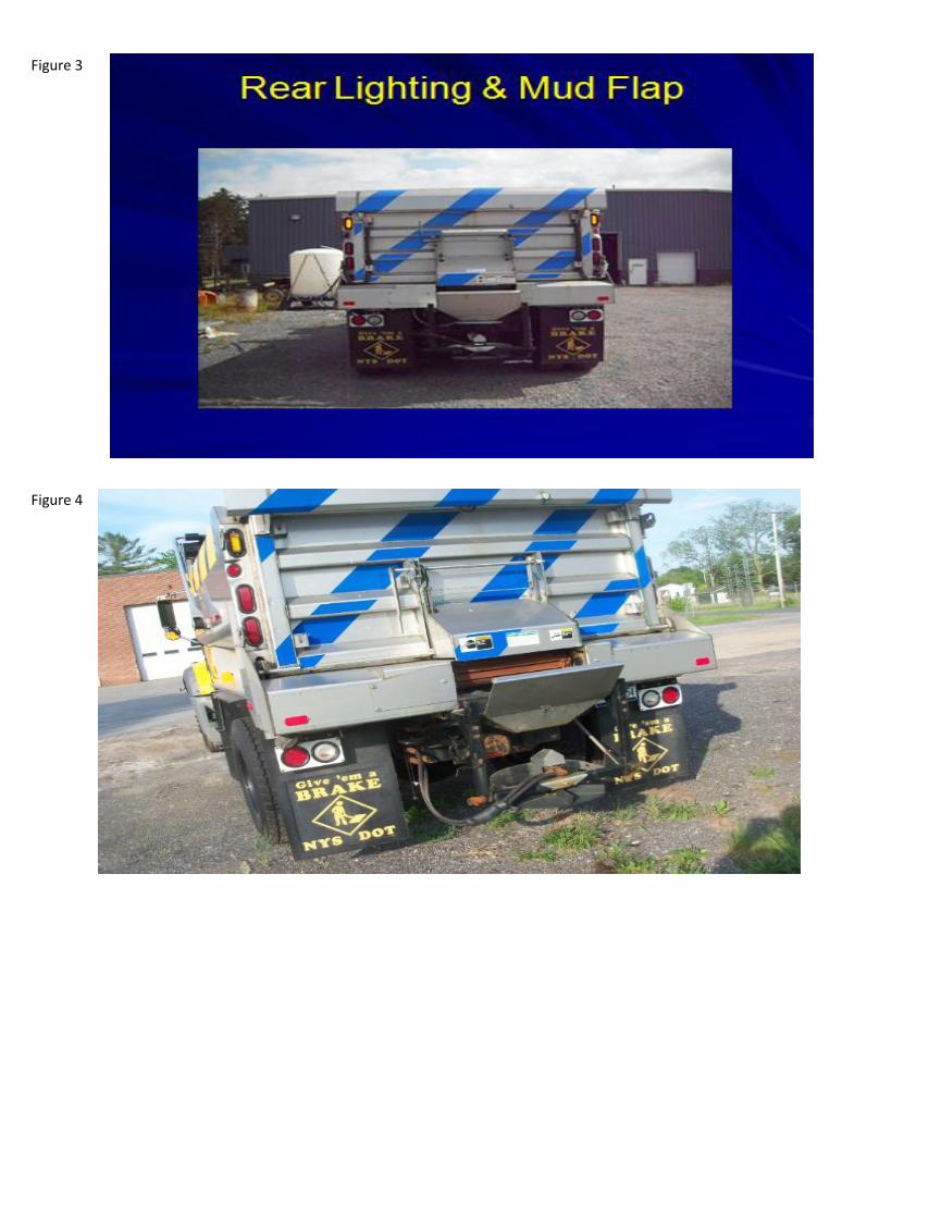
Figure 3
Figure 4

Figure 5
Figure 6
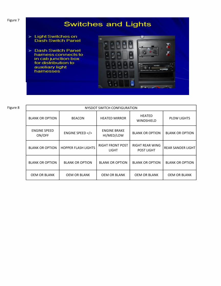
Figure 7
Figure 8 NYSDOT SWITCH CONFIGURATION
BLANK OR OPTION BEACON HEATED MIRRORHEATED
WINDSHIELDPLOW LIGHTS
ENGINE SPEED
ON/OFFENGINE SPEED </>
ENGINE BRAKE
HI/MED/LOWBLANK OR OPTION BLANK OR OPTION
BLANK OR OPTION HOPPER FLASH LIGHTSRIGHT FRONT POST
LIGHT
RIGHT REAR WING
POST LIGHTREAR SANDER LIGHT
OEM OR BLANK OEM OR BLANK OEM OR BLANK OEM OR BLANK OEM OR BLANK
BLANK OR OPTION BLANK OR OPTION BLANK OR OPTION BLANK OR OPTION BLANK OR OPTION

Figure 9
Figure 10
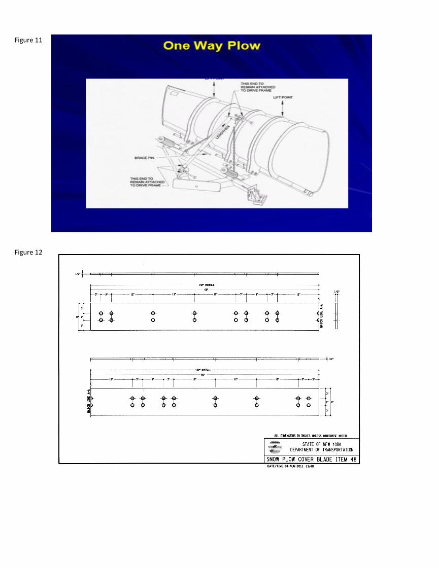
Figure 11
Figure 12

Figure 13
Figure 14

Figure 15
Figure 16
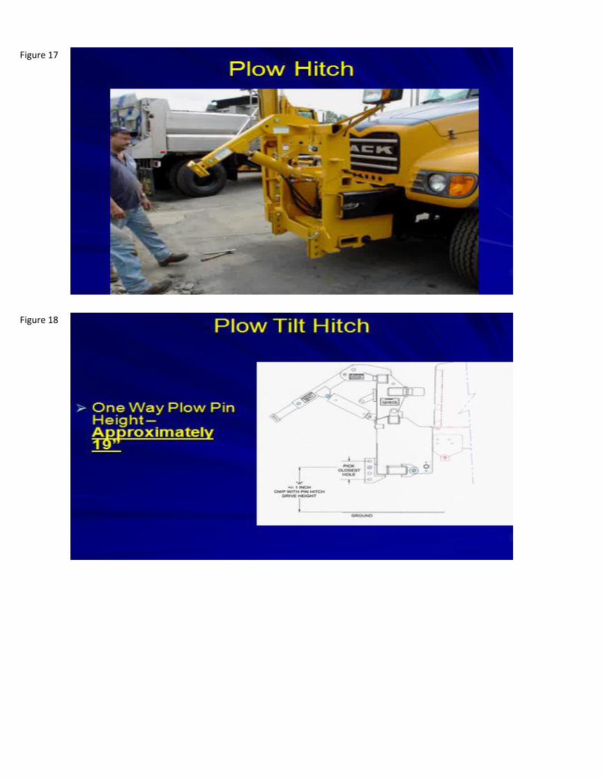
Figure 17
Figure 18

Figure 20
Figure 19

Figure 21

Figure 22

GROUP 40590-22910– TRUCKS, HEAVY DUTY (Class 8 Chassis Cab Type with Various Bodies)
PC67339 Air-Flo Mfg. Co. Inc Price List 1/22/16
Awarded ItemName and effective date of the referenced price
page(s) for the specifications in the Item(s) below
Dump Body or
Plow Discount
AOAC
Discount
Final Order
Due Date
2016 Model Year
NYS Net
Contract Price
2015 Air-Flo Af-Dau-10 10'
Dual Auger UnibodyAIR-FLO NYS OGS 3/1/15 30% 30% TBD $26,000.00
Front Plow: 2015 Henke
OWFA 30-60-11 11' One-
Way Plow
AIR-FLO NYS OGS 3/1/15 30% 30% TBD $39,200.00
Wing Plow: 2015 Air-Flo
Wing SystemAIR-FLO NYS OGS 3/1/15 30% 30% TBD
Include with Front Plow
price
$2.60
CategoryStandard /
Optional
DUMP BODY (please refer
to the Figures tab, figures
1 and 2)
Standard
DUMP BODY Standard
DUMP BODY Standard
DUMP BODY Standard
Specification
A ten foot (10') long, 6.0 cubic yard (with out sideboards) combination dump body, material spreader with rear discharge, and hydraulics &
controls for snowplowing, and material spreading.
Dump Body constructed with a minimum 7-gauge 201 stainless steel (minimum 3.5% nickel content) body components; and gusseted running
boards, rub rails, tailgate, top rails, outer longitundinals, and cab shield will be 10-gauge 201 stainless steel minimum with stainless steel
fasteners and incorporate locking mechanisms.
Mounted in a "set back" position between the front of the body and the back of the cab to permit installation of a snowplow wing box assembly.
Lot IV: Truck Bodies (Single Axle Dump Body and Plow)
Note: The Contractor shall offer the Dump Body, Plow Package and Aftermarket Components at the NYS discount listed below. It shall meet the specifications listed below, unless otherwise agreed upon
between the Contractor and Authorized User(s), as applicable. Discounts are from MSRP. The actual dump body and plow package may exceed the minimum specifications listed below in the Dump Body and
Plow Package Specifications. The Authorized User may elect to add Additional Options and Aftermarket Components (AOAC), delete Options and Aftermarket Components, or substitute a Base Item feature that
is an Option or Aftermarket Component with another Option or Aftermarket Component. All Items must comply with the minimum specifications detailed in Contract Section 3.2 Product Requirements,
including Contract Section 3.2.1 Standards, Codes, Rules, and Regulations. Additional Plow Models may be offered in accordance with Contract Section 3.2.5 Chassis Cab, Truck Body and Plow Substitutions.
Unless otherwise noted, the Dump Body and Plow Package Specifications listed below are considered minimum specifications. See also Contract Sections 3.2.7 Chassis Cab and Truck Body OEM Options and
3.2.8 Aftermarket Components .
Delivery Cost Per Mile
Base Item Specifications
One-piece sides and headsheet, Continuous welds. Full depth rear corner posts tied to formed rear apron. Longitudinals have longsills
page 14 of 24
P:\FileTrans\FleetTeam\40590 Heavy Duty Trucks\22910\03Award\04_SignedFinalContracts\1_Air-Flo_Mfg\22910_AppC-2_ContractPricelist(complete)_Air-Flo_2016-4-12 Lot IV Single Axle
Dump

GROUP 40590-22910– TRUCKS, HEAVY DUTY (Class 8 Chassis Cab Type with Various Bodies)
DUMP BODY Standard
DUMP BODY Standard
DUMP BODY Standard
DUMP BODY Standard
DUMP BODY Standard
DUMP BODY Standard
DUMP BODY Standard
DUMP BODY Standard
DUMP BODY Standard
DUMP BODY Standard
DUMP BODY Standard
DUMP BODY Standard
DUMP BODY Standard
DUMP BODY Standard
DUMP BODY Standard
DUMP BODY Standard
DUMP BODY Standard
Fixed sidewalls and sloped/radius floors ranging between 22° and 45 ° angle to the conveyor floor. Configuration will provide support to the
sidewall/floor and full length/width rubrails. Top rail of curved bodies will be three (3) or four (4) brake, fully enclosed, continuously welded.
Movable sidewall will not be accepted.
Dimensions: Inside Clear Width (nominal) = 7' IW minimum. Overall Width = 102"OAW maximum. Sideboard pockets shall be provided.
Minimum sideboard height 8". Minimum tailgate height to match sideboard height with sideboards installed.
Hoist: Class 60 or better. Trunion mounted cylinder. Mailhot #CS90-4-2 or compatible equivalent.
Dual support struts to hold dump body in raised position. Dump props integrated into the rear hinge are acceptable. Lube hinge point fitted
with zerk grease fitting.
Grease lines/hoses secured to frame with out polymer tie straps @ 18" intervals. Easily accessible grease fitting manifold(s) for servicing
multiple dump body components labeled with manifold termination points.
Tailgate: Rectangular, heavy duty, reinforced with full perimeter, horizontal, and vertical bracing as needed to accommodate one (1) center-
located coal chute with standard. The Tailgate latch/release shall be air operated. It shall incorporate a failsafe system that will insure tailgate
stays latched with the body loaded in up position regardless of air pressure. Top hinged, bottom latching. Hinge pins secured with removable
hitch-pin. Spreader chains will be grade 28 proof-coil type, ⅜" diameter and will permit full use of the tailgate as a body floor extension and
material spreading control. Upper & lower chain eyes/loops for securing the tailgate. Cornerpost lower chain-end securements. "D" ring type
lifting fastener against rear face of the tailgate installed at center top of the upper box section. One vertical sliding chute door, minimum 16"
wide, with control lever & safety chain, centrally located in the tailgate.
Tailgate chute: The operating, adjustment & locking handle/s shall be no higher than mid-height of the tailgate and shall be accessible to all
operators while standing at the vehicle’s grade level. The door opening shall have an adjacent laminated-plastic scale that indicates in 1/2”
increments the door’s actual opening above the conveyor chain bar-flights. Gates with (a) flexible wiper(s) shall have one-inch adjustment slots
in the wiper. Rub rails full length of each side. Running boards/fenders suitable for installation of pre-wetting/anti-icing systems.
A removable, AR400, Minimum 3/16" steel cover plate will be Provided to cover the conveyor for standard dump body use.
Minimum nine inch (9") full width, stainless steel rear apron with side gussets.
A full-height crossmember will be installed at the rear of the chassis that will provide suitable mounting for a pintle hook, up to a twenty-ton
capability.
Cab Shield shall be full-width of dump body.
Ladder: Three (3) piece, Minimum 201 stainless steel ladder attached to the curbside of the body near the front corner. Removable top section
to extend equal to the cab protector height. Center section to extend from the sideboard height to the rub rail. Attached, stowable, and ID Plates: Permanent body ID plates with body model & serial numbers per body, tailgate, and bolt-on extensions.
Material Screens: Fabricated with 3/8" diameter rod set in 1½"x1½" angle iron frame. Grate openings 3" x 3" square, maximum. Secured with
bolts or pins.
Spinner Assembly: Rear discharge arrangement consists of corrosion resistant, adjustable spinner assembly (disc, chute, quick coupler lines,
hydraulic motor, baffle shrouds, weather caps etc.). Spinner assembly will not interfere with dumping capability.
Audible alarm and body up light with all necessary waterproof switches/relays etc. for whenever the dump body is elevated.
page 15 of 24
P:\FileTrans\FleetTeam\40590 Heavy Duty Trucks\22910\03Award\04_SignedFinalContracts\1_Air-Flo_Mfg\22910_AppC-2_ContractPricelist(complete)_Air-Flo_2016-4-12 Lot IV Single Axle
Dump
GROUP 40590-22910– TRUCKS, HEAVY DUTY (Class 8 Chassis Cab Type with Various Bodies)
DUMP BODY (please refer
to the Figures tab, figures
3 and 4)
Standard
HYDRAULICS Standard
HYDRAULICS Standard
HYDRAULICS Standard
HYDRAULICS Standard
HYDRAULICS (please refer
to the Figures tab, figures
5 and 6)
Standard
HYDRAULICS Standard
HYDRAULICS Standard
HYDRAULICS Standard
LIGHTING Standard
LIGHTING Standard
LIGHTING (please refer to
the Figures tab, figures 1 -
4)
Standard
LIGHTING Standard
Control Valves shall be load sense pressure compensated. Accommodate air shift control actuators. Valve stack assembly consist of valve
sections for wings, plow & hoist control, auger, spinner & pre-wet functions controlled by Dickey-John FLEX 4 or compatible equivalent spreader
controls for use with a hot shift PTO. Reference: Rexroth M4 Series, Danfoss PVG 32 Valve or compatible equivalent. Valve shall be enclosed in
10-gauge steel side panels and covers. Air actuated control valves to include automatic oiler. Control levers/joystick controls mounted on raised
console located between cab seats. Air actuator valves to be located above the control valves.
Rubber splashguards, forward and aft of the rear wheels mounted on anti-sail brackets will be provided.
Pump: 60cc, Constant running, PTO driven, continuous duty, load sense. Saur-Danfoss JR-R-060B-LS-14-24-NN-N-3-A3N4 or compatible
equivalent.
The hotshift PTO shall be Chelsea 280 series or compatible equivalent.
Reservoir: 7 USS gauge, 40 gallon capacity complete with baffle, filtered vent, fill port strainer, sight glass & magnetic drain plug, and remote fill
with shutoff valve. Removable tank, integral to the rear wing mast assembly (see diagram at Attachment 17). Hydraulic filter(s) sized for
maximum hydraulic gallon/minute. 100 micron mesh screen on suction strainer. Minimum 35 gallons hydraulic oil in reservoir at delivery.
Cylinders: Meet snowplow specifications. Chrome or nitrided piston rods throughout. Removable heads. Adjustable in-line flow control for
adjusting wing up-down speeds.
Required hydraulic lines consist of both flexible and rigid lines servicing the dump body, front and wing plows, tilt hitch assembly, auger material
spreader, material spreader spinner, load sense assembly, pre-wet systems, etc. Rigid lines will be SAE stainless steel with threaded or
compression brazed fittings. Flexible lines will be "Aeroquip Match Made Plus GH793" SAE 100R-2SN with crimp type fittings. Lines, whether
rigid or flexible, will be sized for maximum flow hydraulic system. Lines secured minimum of 18" intervals. Quick couplers will be steel double
shutoff type with weather cap chained to it. "Snap-Tite", Series, quick disconnect couplers on material spreader lines and plow wings, etc. Lines
routed directly to respective hydraulic motors.
Motors: Shall be sized to accomplish spreading operations. See application rates noted in "Spreader Control" section below.
H Series or compatible equivalent steel quick couplers throughout.
Body lighting will be LED except for plowing assembly head lights and roof-mounted remote spotlights.
Body Lighting will consist of: (1) Rear Stop/Tail/Turn lights (2) Rear License Plate lights (3) Three-Light Cluster Bar (4) Clearance lights (5)
Auxiliary lights (i.e. plow headlights, wing plow lights, curb side wing plow post lighting, warning lights, (1) cab / Stantion-mounted spotlight, and
area lights for material spreaders and underbody scrapers).
Rear stop/tail/direction/back-up lights: Two separate sets of lights are required. One set will be recessed in the in the rear face of the body's
rear corner posts. This set will consist of two (2) Truck-Lite Series 60, #60700 red lamps and one (1) yellow flasher (Whelen #NYSDOTSY4) per
side . Additionally, a second set will be installed on the underside forward of the rear edge of the body apron. This set will consist of LED
Stop/turn/Tail light and white back-up light.
Rear license plate lights & brackets - Truck-Lite 15011.
page 16 of 24
P:\FileTrans\FleetTeam\40590 Heavy Duty Trucks\22910\03Award\04_SignedFinalContracts\1_Air-Flo_Mfg\22910_AppC-2_ContractPricelist(complete)_Air-Flo_2016-4-12 Lot IV Single Axle
Dump
GROUP 40590-22910– TRUCKS, HEAVY DUTY (Class 8 Chassis Cab Type with Various Bodies)
LIGHTING Standard
LIGHTING Standard
LIGHTING Standard
LIGHTING Standard
LIGHTING Standard
LIGHTING Standard
LIGHTING Standard
LIGHTING Standard
LIGHTING (please refer to
the Figures tab, figures 7
and 8)
Standard
WIRING & CIRCUITRY Standard
WIRING & CIRCUITRY Standard
WIRING & CIRCUITRY Standard
WIRING & CIRCUITRY Standard
SPREADER CONTROLS Standard
FRONT PLOW & RIGHT
WING
Standard
Curb side wing plow lights, Truck-Lite #80374 or compatible equivalent, mounted on wing post to illuminate the curb area.
LED Three-Light Cluster Bar light similar to Peterson #4442 shall be installed in a protected area at the rear of the chassis or on the rear hoist
crossmember.
Clearance lights shall be Truck-Lite Model 10 series recessed in the outer corners of the rear body posts.
Plow head lights shall be Halogen type, Truck-Lite model 80893 or compatible equivalent. Fixture to include turn and marker lights. Mounted on
top crossmember of the snowplow hitch assembly. Extension posts will be used, as needed, to project the light beam over a raised plow.
Wing plow area lights, Truck-Lite #80360, mounted to provide operating lighting of wing plows.
Warning lights will consist of two (2) non-synchronized LED flashing, amber warning assemblies secured to mounting plates and located atop a
lateral horizontal crossmember mounted on two vertical risers attached directly to the frame rails between the cab and the truck's body. Light
assembly Whelen #L21-NYS.
1 (One) Cab / Stanchion-mounted Spot light (i.e.; Go Light model 2020, KH night ray, or compatible equivalent)."
Auxiliary area lighting illuminating material spreader areas, Truck-Lite #80360 or compatible equivalent.
Truck OEM provided switching shall be used for all warning and auxiliary lighting, if available. Switch positioning will be resolved at a pre-order
meeting. A sample switch position illustration is provided in figure 8.
Sealed wiring harness from front of truck to all electrical components at the rear of the truck - similar to Truck-Lite "Modular Sealed Harness
System" including weather proof junction box, Truck-Lite 50800/50400 or compatible equivalent. Sealed harness continues to all body and
chassis lights and includes a sealed corrosion resistant seven (7) way A.T.A. trailer plug and lead assembly mounted on the rear crossmember .
Sealed system includes weatherproof components to include ATA connectors, wiring cable, cable connectors, housing boots, and junction boxes
(Truck-Lite series noted previously). Connections treated with electrical compound grease (Truck-lite #97948).
All wiring harnesses from the waterproof junction box shall be two conductors, minimum, having power and neutral/ground wires. All wiring
shall be secured, where possible, to the inside web of the frame at eighteen (18") inch intervals using plastic wire clamps or ties.
Hazard Warning System: The 4-way flashing, hazard warning system shall be operable regardless of the position of the ignition switch and/or
parking brake.
Junction box in the cab for all accessory lighting.
Control console mounting to be determined at pilot model inspection meeting.
A one-way right front snowplow, a tilting front hitch assembly, and single curbside patrol type wing plow.
page 17 of 24
P:\FileTrans\FleetTeam\40590 Heavy Duty Trucks\22910\03Award\04_SignedFinalContracts\1_Air-Flo_Mfg\22910_AppC-2_ContractPricelist(complete)_Air-Flo_2016-4-12 Lot IV Single Axle
Dump

GROUP 40590-22910– TRUCKS, HEAVY DUTY (Class 8 Chassis Cab Type with Various Bodies)
FRONT PLOW (please
refer to the Figures tab,
figures 10 and 11)
Standard
FRONT PLOW Standard
COVER BLADE (DOT ITEM
B48, please refer to the
Figures tab, figure 12)
Standard
CARBIDE CUTTING EDGES
(DOT ITEM B28 & B29,
please refer to the Figures
tab, figures 13 and 14)
Standard
TUNGSTEN CARBIDE
INSERTS
Standard
NOSE SHOE (DOT Item 15 -
please refer to the Figures
tab, figure 15)
Standard
PUSH FRAME WEAR SHOE
(please refer to the
Figures tab, figure 16)
Standard
Fasteners Standard
All Plow Moldboards shall have: Cover Blade (Item B48) mounted on face of cutting edge = ½" x 8" one-piece SAE 1080 steel, AASHTO (standard
highway) punched (11/16" for ⅝ bolts). Three (3) SAE 1020 steel cutting edges, two (2) sections = 48"x 61/8" x ¾" sections (DOT Item B29) and
one (1) section = 36"x 61/8" x¾" section (DOT Item B28) with tungsten carbide inserts.
The front plow shall be 11' long at the cutting edge, be a minimum 30" high at the nose, and a minimum 53" at the discharge end. Minimum
seven (7) gauge continuous welded Grade 50 steel welded to ½" one-piece vertical ribs (horizontal reinforcements as needed). Reinforced
4"x4"x¾" minimum, steel bottom angle with welded-in reinforcing gussets. Full width 12" rubber deflector. Adjustable stabilizing arm with
safety shear pin allowing for an adjustable attack angle - minimum 30° to 45°. Two (2) cast push frame wear shoes mounted to adjustable shoe
mounts . One (1) nose show at the leading edge end. A minimum of two high tensile chains shall be provided to lift the front plow moldboard to
a nearly level plane. Weight approximately 2,000 lb. NOTE: In addition to the manufacturer's standard offering, all one-way plows, regardless
of configuration, must be supplied with an additional trip spring retainer. References: Henderson 30"-53"-11'; Viking 3564 HSE 9; Henke 30-60-
11IS; or compatible equivalent.
SAE 1080 Steel Cover Blade - Plow: Cover Blade mounted on face of cutting edge = ½"x 8" one-piece SAE 1080 steel, AASHTO (standard highway)
punched (11/16" for ⅝ bolts).
Item B28 (3') and Item B29 (4') Carbide Cutting Edges. ¾"x 61/8" one-piece cutting edge with AASHO center punching standard.
1. 1" long x 0.575" wide x 0.375" thick. 2. Cobalt content = 11.0 to 12.0%; Tungsten Carbide = 87.0 to 88.0%; all other elements 1.0% maximum.
3. Visible surface cracks in a maximum of 15% of the insert. 4. Hardness (HRA) = 88.0 to 90.5. 5. Density (g/cc) = 14.40 to 14.55. 6. Porosity =
A00 to A04; B00 to B02; C00 to C04. 7. Grain size = 10-M/10-C.
The plow shall be equipped with one nose frame wear shoe (DOT Item #15).
The plow shall be equipped with two push frame wear shoes. The shoes shall attach to adjustable brackets with a fixed shoe at the front of the
push frame.
Plows and Hitch Assemblies = Grade 8 bolts & nuts. SAE Hardened washers. Shall have high quality corrosion resistant finish. Washers shall be
used between oblong slots and the head and/or nut of the fastener(s). Holding & lockout pins shall be painted to match the components they
are connecting or have a non-paintable, corrosion-resistant coating/plating.
page 18 of 24
P:\FileTrans\FleetTeam\40590 Heavy Duty Trucks\22910\03Award\04_SignedFinalContracts\1_Air-Flo_Mfg\22910_AppC-2_ContractPricelist(complete)_Air-Flo_2016-4-12 Lot IV Single Axle
Dump

GROUP 40590-22910– TRUCKS, HEAVY DUTY (Class 8 Chassis Cab Type with Various Bodies)
PUSH FRAME Standard
PUSH FRAME Standard
PUSH FRAME Standard
PUSH FRAME Standard
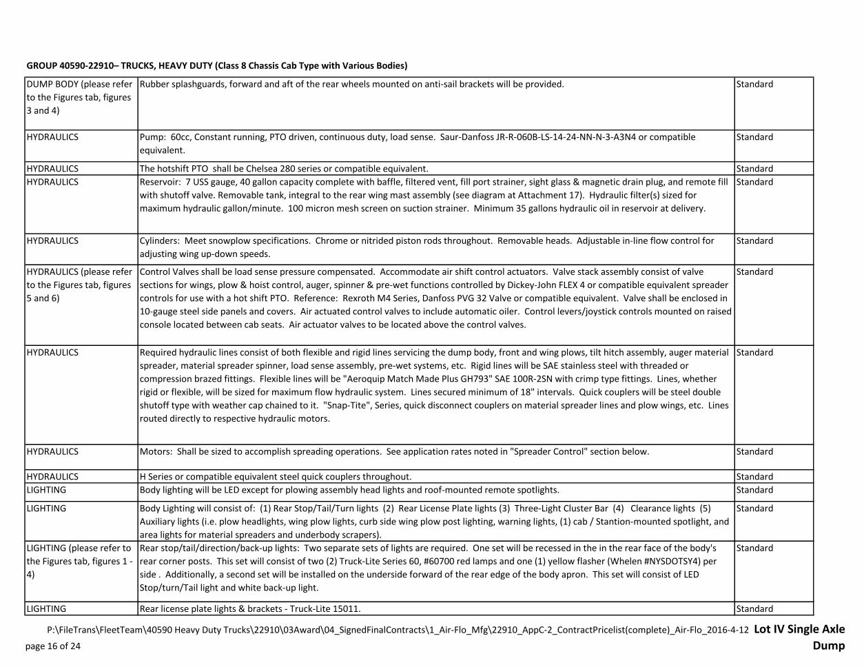
POWER TILT HITCH (please
refer to the Figures tab,
figures 17 and 18)
Standard
POWER TILT HITCH Standard
POWER TILT HITCH Standard
POWER TILT HITCH Standard
POWER TILT HITCH Standard
POWER TILT HITCH Standard
Tilt frame consists of two (2) vertical members of 4"x3"x3/8" steel tubing welded to 6"x4"x¾" angle and ¾"x3" plate at the base of the tilt frame
to support 5/8" plate 4 position drive plates.
The driveframe shall consist of two truss members, a main drive crossmember, an oscillating drive bar and minimum of two trip spring
moldboard attachment assemblies. The truss members shall be fabricated from 5"x5"x1/4" wall structural steel tubing (or equal design
strength). The main drive crossmember shall be constructed from 6"x6"x1/2" steel angle reinforced with 1/4" steel plate. At the rear of the
driveframe, the truss members shall be welded to a piece of 1" plate, 6" wide x 30 3/4" long which forms a bearing surface for the oscillating
drive bar. The trip spring assemblies shall be welded to the main drive angle. It shall consist of a minimum of two 45 degree slotted hinge lugs
which shall be attached by 1-1/4" hardened steel pins connecting the moldboard to the main drive frame angle. Connected to the two outside
slotted members shall be a slide/trip spring assembly consisting of a sliding weldment, 1-1/4" diameter threaded rod and nut for spring pressure
adjustment, a spring pressure plate, and 5-1/4" diameter x 12½" long compression spring made from 5/8" diameter wire with a minimum of 9
coils (or compatible equivalent). The springs shall compress whenever the plow encounters surface obstructions and shall not attach directly to
the moldboard, so to eliminate cutting edge adjustment interference. Safety chains/cable shall be attached to the compression springs to
safeguard their coming loose. Weight of complete plow and push frame approximately 2,200 lb.
The moldboard shall have a safety chain between it and the push frame that ensures the plow cannot tip forward onto anyone during attack
angle strut adjustment or failure of the mounting pins.
An adjustable strut shall be provided to permit variations in cutting edge to ground plane angle. Adjustment shall be provided by a tubular
telescopic brace attached to the top of the moldboard assembly and to the driveframe assembly. It will be adjustable without the use of tools.
The outer tube shall be fabricated from hot rolled 2.75" O.D. x 0.344W mechanical pipe and the inner arm shall be from 2" O.D. solid bar stock.
The oscillating drive bar shall be made from 3/4" thick plate, 6" wide x 34" long. It shall attach to and oscillate about the rear bearing plate on a
minimum 1-1/2" grade 8 bolt with castellated nut and cotter pin. The bearing plate and drive bar shall allow the plow to follow the contour of
the road to the right or left. The drive bar shall be equipped with two 3/4" drive ears on 31" centers with minimum 1-3/8" pinning holes.
Secured with Grade 8 hex head bolt with castellated nut and cotter pin.
Hitch is a heavy duty snow plow hitch for use with a single patrol wing and capable of hydraulically tilting forward to accommodate a chassis tilt
hood. Unit consists of truck and plow portions. Approximate height is 60", width 42". Will have continuous seam welding.
Drive pin plates are on 30½" centers. Four (4), ¾" pivot plates are welded to the bottom 7"x4"x3/8" tube horizontal member.
Bottom vertical and horizontal members are reinforced at the rear by two (2) 6½"x8"x3/8" gussets. Top member 4"x4"x3/8" wall tubing is
welded to two (2) ½" upper side plates which are welded to the upper tube member and the two (2) vertical tube members.
Two (2) ½" lift arm plates are reinforced by two (2) 10"x6"x3/8" gussets. A locking tab (for stored cylinder position) is welded to a center
member of 4"x3"x½" angle.
The wing post supporting members are designed for high mast leveling or patrol type wing. The tilt frame shall include a lift lug, safety tilt chain,
tilt portion outer alignment guides, two (2) tilt pin storage brackets, and a license plate bracket.
page 19 of 24
P:\FileTrans\FleetTeam\40590 Heavy Duty Trucks\22910\03Award\04_SignedFinalContracts\1_Air-Flo_Mfg\22910_AppC-2_ContractPricelist(complete)_Air-Flo_2016-4-12 Lot IV Single Axle
Dump

GROUP 40590-22910– TRUCKS, HEAVY DUTY (Class 8 Chassis Cab Type with Various Bodies)
POWER TILT HITCH Standard
POWER TILT HITCH Standard
POWER TILT HITCH Standard
POWER TILT HITCH Standard
FRONT PLOW LIFT
ASSEMBLY
Standard
LIFT CYLINDER Standard
HARDWARE Standard
CYLINDER RODS Standard
WING PLOW (please refer
to the Figures tab, figure
19)
Standard
WING PLOW Standard
All snow plow hydraulic cylinder rods shall be chrome or nitrided and have a rod wiper to clean the piston rod as it retracts into the cylinder
tube.
The front wing lower mounting tube is 7"x4"x3/8" tubing notched into the lower outside side plate weldments and welded to the inner tilting
vertical riser tubes.
The upper wing post mounting tube is 4"x4"x3/8" and gusseted with 3/8" plate. The tube is fully welded to the upper tilting portion of the side
plates and to the backside of the vertical riser tubes. Two (2), ¼"x2"x13" plow light brackets will be welded to the upper post tube at a height
that accommodates both one-way and reversible front plow moldboard heights.
The sideplate frame weldment is constructed of two (2) ½" plates and a top horizontal member of 4"x4"x3/8" tubing. Four (4), ½" anti-tilt pivot
plates will be welded to the top of the horizontal member. Cylinder base support plates shall be reinforced. Tilting is accomplished by removing
the two (2), 1" minimum anti-tilt pins and inserting a tilting pin through the lift arm and support plate and extending the cylinder. The tilt frame
pivots are two (2), minimum 1½" pins. The lift arm and hitch frame shall be designed with a minimum 4"x10" double acting lift cylinder with
chrome or nitrided cylinder rod. Cylinder pins are 1" cold rolled steel.
The hitch allows for proper plow vertical adjustment with minimum 3 plow attachment point options. Two (2), 1-1/4" zinc plated plow
attachments pins (shall be no-turn type).
The front plow hitch and lifting assembly shall be constructed of heavy steel members attached to the chassis frame. The design shall disperse
plowing stresses and shock forces to the chassis frame. The hitch shall be designed to facilitate minimum vehicle degree turning radii (i.e.
plowing shall not change chassis minimum turning radii) without interfering with plow or chassis components. Front plow lifting shall be
accomplished via a "Power Tilt" design by a double-acting hydraulic ram through an appropriate level and linkage arrangement.
The plow lift cylinder shall be double acting with a minimum 4" bore, 10" stroke, chrome or nitrided piston rod and a wiper to clean the piston as
it retracts into the cylinder. The base of the cylinder shall attach to the horizontal member noted above, while the cylinder rod attaches to a
horizontal, pivoting lift yoke weldment fabricated from 3/4" plate. It shall be possible to lockout the plow lift action and instead hydraulically tilt
the entire center portion of the plow attachment (and any applicable side wing appurtenances) forward so to accommodate a tilt hood truck
chassis. This function shall use the same cylinder as noted above. In addition, it shall be possible with the removal of four pins, to expediently
detach the plow lift device (and any applicable wing appurtenances) from the custom truck attachment for summer truck use.
Mounting fasteners and pins for primary component mounting (i.e. chassis frame to cheek plates, brackets to frame, etc.) shall be grade 8
strength. Other hitch connection bolts shall be grade 5 minimum. All bolts, nuts, and chain shall be zinc plated.
Single curbside patrol type wing plow assembly consisting of the wing plow moldboard assembly, front mast assembly, wing braces, and a rear
mast assembly including a hydraulic reservoir assembly.
The rate of wing-plow descent, from full-up to full-down position, shall be at least 4 seconds. Maximum stowed width is 138” (inches). Stowed
configuration shall not interfere with any other components (i.e. rear braces, exhaust pipes & shielding, mirrors, etc.). Removable front mast
which attaches to front-mounted plow hitch. Sight markers required.
page 20 of 24
P:\FileTrans\FleetTeam\40590 Heavy Duty Trucks\22910\03Award\04_SignedFinalContracts\1_Air-Flo_Mfg\22910_AppC-2_ContractPricelist(complete)_Air-Flo_2016-4-12 Lot IV Single Axle
Dump
GROUP 40590-22910– TRUCKS, HEAVY DUTY (Class 8 Chassis Cab Type with Various Bodies)
WING PLOW Standard
WING PLOW
COMPONENTS (please
refer to the Figures tab,
figures 12 - 14, 16, and 19)
Standard
WING PLOWS Standard
WING BRACES Standard
WING BRACES
HYDRAULICS
Standard
FRONT MAST Standard
Moldboard minimum 7 USS gauge Grade 50 steel, ribbed, reinforced, braced for strength to meet warranty time periods. Nose height minimum
27". Trailing end height minimum 36". Minimum 11' Long. Full trip design. A dual vertical rib shall be provided at the trailing end of the wing-
plow. It shall have eyeholes for the upper and lower rear wing-plow braces. The trailing end of the wing-plow(s) shall be diagonally cut back
(approx. 45°). The horizontal cutting edge reinforcement shall be not less than 5” x 3-1/2” x 3/4” steel angle with welded-in reinforcing gussets.
To facilitate cab entry, a non-slip step shall be provided on the inner side of the wing-plow(s).
Wing Moldboard Assemblies shall have: Cover Blade (DOT ITEM B48) mounted on face of cutting edge = ⅝"x 6" one-piece SAE 1080 steel,
AASHTO (standard highway) punched (11/16" for ⅝ bolts). Three (3) SAE 1020 steel cutting edges, two (2) sections = 48"x6"x¾" sections (DOT
Item 29) and one (1) section = 36"x6"x¾" section (DOT Item 28) with tungstem carbide inserts. Leading cover blade & cutting edge cut/tapered
to approximately 45°. Shall be fabricated to accept two (2) wear shoes designated DOT Item #19 or #19A.
A link-chain grab hook shall be provided on the bottom reinforcement angle at its trailing end for attaching a safety chain.
A pair of telescoping type, parallel wing braces, shall support the rear of wing-plow(s). They shall be constructed of a minimum 2.88' O.D. x
0.31W hot rolled mechanical steel pipe outer tubes (reinforced at the telescoping end/s), and a 2-1/8” diameter steel rod inner member/s. The
wing braces shall be mounted to the moldboard via a fixed bracket (i.e., gusset reinforced dual vertical reinforcing rib at trailing end of
moldboard). The top brace shall be free to telescope and retract as the moldboard trips and returns. It shall be retracted by a heavy-duty
tension spring with means for tension adjustment. The spring shall be placed on the forward side of the top brace. The active end of the return
spring shall be an adjustment collar, or functional equivalent, setting the angle of the wing-plow and its clear plowing track. Regardless of
whether braces are to be installed on the left or right side of the vehicle, their design & final assembly shall ensure that when installed the braces
shall have their vertical hinge-pin bolts with heads oriented upward. The grease fitting on the braces' swivel collars shall be on the forward side
of the collars. A lockout pin shall be provided to permit non-trip operation. The lockout pin when not in use shall be stored adjacently on the
back of the wing-plow moldboard/ribbing in an appropriate bore or tube. The lockout and adjustment pins shall be held in place by retaining
pins as specified elsewhere herein. The lower brace shall be designed to permit setting the angle of the wing-plow (currently a 9° attack angle)
and its clear plowing width. Grade 2 shear pins shall be provided.
A minimum 3" double-acting hydraulic cylinder shall accomplish the raising and lowering of the trailing end of the wing plow. An adjustable
flow control shall control rate of wing descent if wing descent can not be controlled at the valve. Speed control valves shall be at inward side of
the post. The cylinder shall be mounted diagonally between the rear parallel wing braces. The cylinder’s stroke length shall be adequate to raise
wing into a cab-tight travel position. The hoses to the lift cylinder shall have double-shut-off-quick-couplers at the rear post transition area. The
lifting cylinder shall be protected against hose failure/rupture & impact loads (permits cylinder rod extension/retraction as needed for wing-plow
full trip condition) by the addition of a counterbalance valve at the base end of the cylinder. The rear slide and parallel brace configuration shall
incorporate a safety chain to hold stored wing up safely.
The front mast (wing plow mounting posts) shall be constructed from an 8" I-beam of 18.4 #/ft with a slideway on its outer side. Built into the
top of the beam shall be a sheave housing which shall incorporate a 5" O.D. sheave turning on a 1" cold drawn steel pin with grease fitting. The
sheave shall be equipped with a bronze bushing. The front mast shall be bolted to, and supported by a lower cross-member fabricated from not
less than 7"x4"x3/8" wall rectangular tubing extending from the bottom of the truck attachment.
page 21 of 24
P:\FileTrans\FleetTeam\40590 Heavy Duty Trucks\22910\03Award\04_SignedFinalContracts\1_Air-Flo_Mfg\22910_AppC-2_ContractPricelist(complete)_Air-Flo_2016-4-12 Lot IV Single Axle
Dump
GROUP 40590-22910– TRUCKS, HEAVY DUTY (Class 8 Chassis Cab Type with Various Bodies)
FRONT MAST Standard
FRONT MAST CYLINDER Standard
WING SLIDE ASSEMBLY Standard
REAR MAST/WING
CABINET FRAME
ASSEMBLY
Standard
REAR MAST OIL
RESERVOIR (please refer
to the Figures tab, figure
20)
Standard
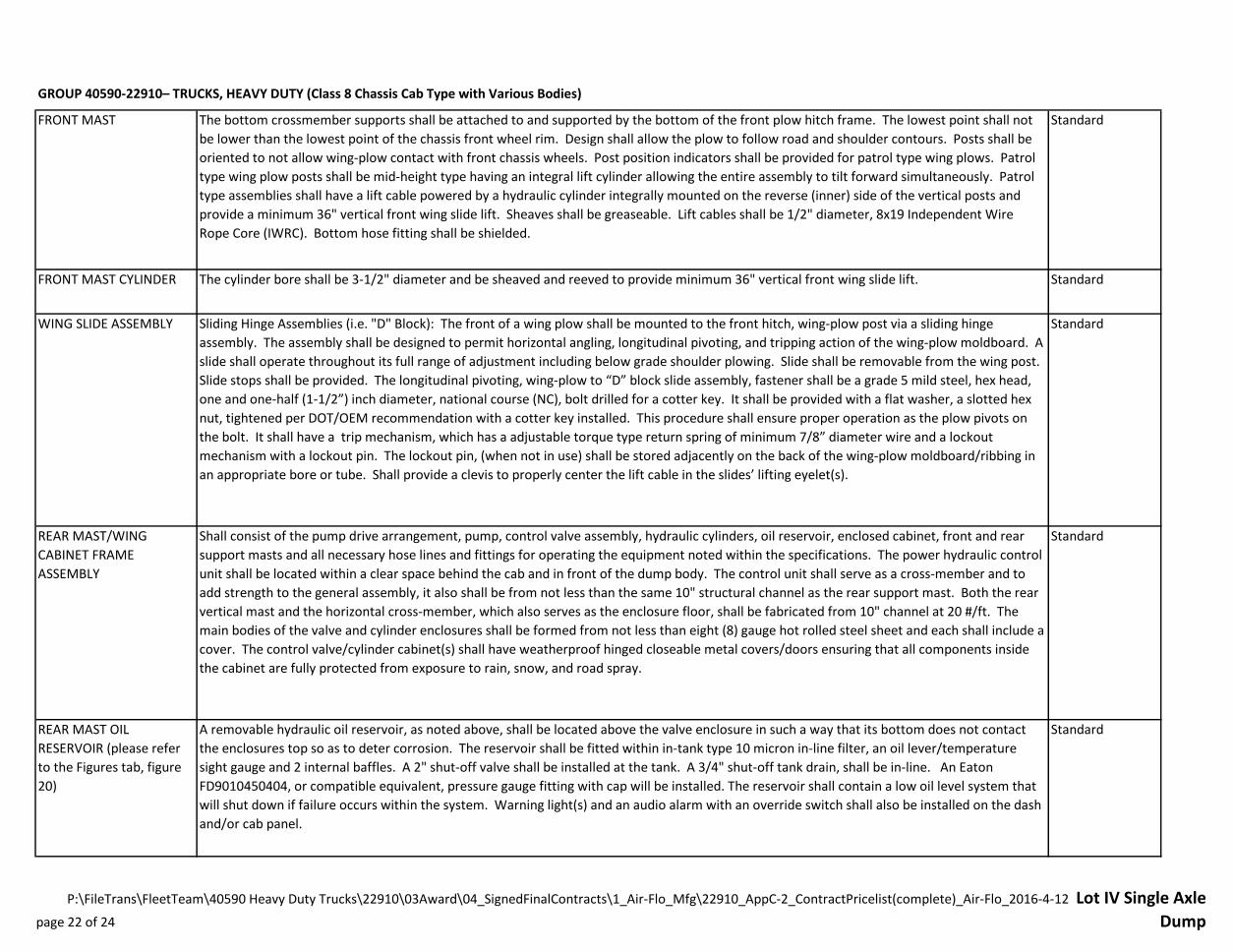
Shall consist of the pump drive arrangement, pump, control valve assembly, hydraulic cylinders, oil reservoir, enclosed cabinet, front and rear
support masts and all necessary hose lines and fittings for operating the equipment noted within the specifications. The power hydraulic control
unit shall be located within a clear space behind the cab and in front of the dump body. The control unit shall serve as a cross-member and to
add strength to the general assembly, it also shall be from not less than the same 10" structural channel as the rear support mast. Both the rear
vertical mast and the horizontal cross-member, which also serves as the enclosure floor, shall be fabricated from 10" channel at 20 #/ft. The
main bodies of the valve and cylinder enclosures shall be formed from not less than eight (8) gauge hot rolled steel sheet and each shall include a
cover. The control valve/cylinder cabinet(s) shall have weatherproof hinged closeable metal covers/doors ensuring that all components inside
the cabinet are fully protected from exposure to rain, snow, and road spray.
The bottom crossmember supports shall be attached to and supported by the bottom of the front plow hitch frame. The lowest point shall not
be lower than the lowest point of the chassis front wheel rim. Design shall allow the plow to follow road and shoulder contours. Posts shall be
oriented to not allow wing-plow contact with front chassis wheels. Post position indicators shall be provided for patrol type wing plows. Patrol
type wing plow posts shall be mid-height type having an integral lift cylinder allowing the entire assembly to tilt forward simultaneously. Patrol
type assemblies shall have a lift cable powered by a hydraulic cylinder integrally mounted on the reverse (inner) side of the vertical posts and
provide a minimum 36" vertical front wing slide lift. Sheaves shall be greaseable. Lift cables shall be 1/2" diameter, 8x19 Independent Wire
Rope Core (IWRC). Bottom hose fitting shall be shielded.
The cylinder bore shall be 3-1/2" diameter and be sheaved and reeved to provide minimum 36" vertical front wing slide lift.
Sliding Hinge Assemblies (i.e. "D" Block): The front of a wing plow shall be mounted to the front hitch, wing-plow post via a sliding hinge
assembly. The assembly shall be designed to permit horizontal angling, longitudinal pivoting, and tripping action of the wing-plow moldboard. A
slide shall operate throughout its full range of adjustment including below grade shoulder plowing. Slide shall be removable from the wing post.
Slide stops shall be provided. The longitudinal pivoting, wing-plow to “D” block slide assembly, fastener shall be a grade 5 mild steel, hex head,
one and one-half (1-1/2”) inch diameter, national course (NC), bolt drilled for a cotter key. It shall be provided with a flat washer, a slotted hex
nut, tightened per DOT/OEM recommendation with a cotter key installed. This procedure shall ensure proper operation as the plow pivots on
the bolt. It shall have a trip mechanism, which has a adjustable torque type return spring of minimum 7/8” diameter wire and a lockout
mechanism with a lockout pin. The lockout pin, (when not in use) shall be stored adjacently on the back of the wing-plow moldboard/ribbing in
an appropriate bore or tube. Shall provide a clevis to properly center the lift cable in the slides’ lifting eyelet(s).
A removable hydraulic oil reservoir, as noted above, shall be located above the valve enclosure in such a way that its bottom does not contact
the enclosures top so as to deter corrosion. The reservoir shall be fitted within in-tank type 10 micron in-line filter, an oil lever/temperature
sight gauge and 2 internal baffles. A 2" shut-off valve shall be installed at the tank. A 3/4" shut-off tank drain, shall be in-line. An Eaton
FD9010450404, or compatible equivalent, pressure gauge fitting with cap will be installed. The reservoir shall contain a low oil level system that
will shut down if failure occurs within the system. Warning light(s) and an audio alarm with an override switch shall also be installed on the dash
and/or cab panel.
page 22 of 24
P:\FileTrans\FleetTeam\40590 Heavy Duty Trucks\22910\03Award\04_SignedFinalContracts\1_Air-Flo_Mfg\22910_AppC-2_ContractPricelist(complete)_Air-Flo_2016-4-12 Lot IV Single Axle
Dump

GROUP 40590-22910– TRUCKS, HEAVY DUTY (Class 8 Chassis Cab Type with Various Bodies)
REAR MAST CYLINDERS Standard
REAR MAST VALVE BANK Standard
REAR MAST VALVE BANK
CONTROLS
Standard
REAR WING PLOW POST
ASSEMBLY
Standard
REAR SLIDE ASSEMBLY Standard
PAINT StandardPlow components shall be powder-coated or painted.
Rear slide cylinder shall not be less than a 3" diameter double acting high-rise type, located outside the rear mast vertical support beam with a
minimum 20" travel.
The supplied valve bank assembly shall be a load-sensing design having a minimum flow rating of 40 GPM with nominal pressures to 5,000 PSI. It
shall have an adjustable relief on the inlet section pre-set higher than the pump. The valve assembly shall include working sections for the plow,
wing, and body/material spreader functions. Air actuator valves shall be on of the control valves.
All valve control actuation shall be accomplished via proportionally balanced pneumatic over hydraulic air controllers and cylinders. The control
shall be located on a pedestal-mounted pivoting console, which will adjust to accommodate either the driver or wingman operation. Control
shall include a secondary filter, regulator, and lubricator.
The vertical wing-plow post shall be a ten (10”) inch “I” beam or a ten (10”) inch “C” channel, with flange widths sufficient to accept the plow
wing slide assembly(ies). Braces, including one projecting rearward at approximately 45°, shall be provided between the bottom of the post and
the chassis frame.
The rear slide shall have a pair of double shear eyehole weldments. The weldments should be angled forward to align with the rear braces and
have gusset reinforcement(s) to ensure proper mount strength. Weldment(s) with double shear eyeholes for attaching the lifting cylinder shall
be provided on the slide. The rear slide may require a notch (inverted “U” shape) at its bottom edge. The notch shall ensure that the slide
functions throughout its full range of adjustment including below grade shoulder plowing. The rear slide and parallel brace configuration shall
incorporate a safety chain to hold stored wing up safely. Slide stops shall be provided.
page 23 of 24
P:\FileTrans\FleetTeam\40590 Heavy Duty Trucks\22910\03Award\04_SignedFinalContracts\1_Air-Flo_Mfg\22910_AppC-2_ContractPricelist(complete)_Air-Flo_2016-4-12 Lot IV Single Axle
Dump
GROUP 40590-22910– TRUCKS, HEAVY DUTY (Class 8 Chassis Cab Type with Various Bodies)
PC67339 Air-Flo Mfg. Co. Inc Price List 1/22/16
Awarded ItemName and effective date of the referenced price
page(s) for the specifications in the Item(s) below
Dump Body or
Plow Discount
AOAC
Discount
Final Order
Due Date
2016 Model Year
NYS Net
Contract Price
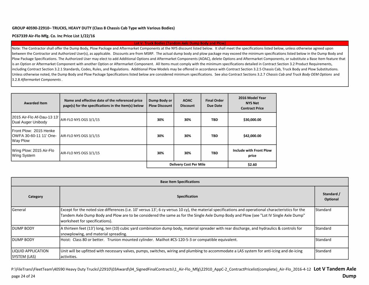
2015 Air-Flo Af-Dau-13 13'
Dual Auger UnibodyAIR-FLO NYS OGS 3/1/15 30% 30% TBD $30,000.00
Front Plow: 2015 Henke
OWFA 30-60-11 11' One-
Way Plow
AIR-FLO NYS OGS 3/1/15 30% 30% TBD $42,000.00
Wing Plow: 2015 Air-Flo
Wing SystemAIR-FLO NYS OGS 3/1/15 30% 30% TBD
Include with Front Plow
price
$2.60
CategoryStandard /
Optional
General Standard
DUMP BODY Standard
DUMP BODY Standard
LIQUID APPLICATION
SYSTEM (LAS)
Standard
Lot V: Truck Bodies (Tandem Axle Dump Body and Plow)
Note: The Contractor shall offer the Dump Body, Plow Package and Aftermarket Components at the NYS discount listed below. It shall meet the specifications listed below, unless otherwise agreed upon
between the Contractor and Authorized User(s), as applicable. Discounts are from MSRP. The actual dump body and plow package may exceed the minimum specifications listed below in the Dump Body and
Plow Package Specifications. The Authorized User may elect to add Additional Options and Aftermarket Components (AOAC), delete Options and Aftermarket Components, or substitute a Base Item feature that
is an Option or Aftermarket Component with another Option or Aftermarket Component. All Items must comply with the minimum specifications detailed in Contract Section 3.2 Product Requirements,
including Contract Section 3.2.1 Standards, Codes, Rules, and Regulations. Additional Plow Models may be offered in accordance with Contract Section 3.2.5 Chassis Cab, Truck Body and Plow Substitutions.
Unless otherwise noted, the Dump Body and Plow Package Specifications listed below are considered minimum specifications. See also Contract Sections 3.2.7 Chassis Cab and Truck Body OEM Options and
3.2.8 Aftermarket Components .
A thirteen feet (13') long, ten (10) cubic yard combination dump body, material spreader with rear discharge, and hydraulics & controls for
snowplowing, and material spreading.
Hoist: Class 80 or better. Trunion mounted cylinder. Mailhot #CS-120-5-3 or compatible equivalent.
Unit will be upfitted with necessary valves, pumps, switches, wiring and plumbing to accommodate a LAS system for anti-icing and de-icing
activities.
Delivery Cost Per Mile
Specification
Base Item Specifications
Except for the noted size differences (i.e. 10' versus 13'; 6 cy versus 10 cy), the material specifications and operational characteristics for the
Tandem Axle Dump Body and Plow are to be considered the same as for the Single Axle Dump Body and Plow (see "Lot IV Single Axle Dump"
worksheet for specifications).
page 24 of 24
P:\FileTrans\FleetTeam\40590 Heavy Duty Trucks\22910\03Award\04_SignedFinalContracts\1_Air-Flo_Mfg\22910_AppC-2_ContractPricelist(complete)_Air-Flo_2016-4-12 Lot V Tandem Axle
Dump