Appendix A Introduction to MATLAB and Simulink978-3-319-18105...Appendix A: Introduction to MATLAB...
94
Appendix A Introduction to MATLAB and Simulink In this appendix, we will discuss MATLAB and Simulink. Note that we will only cover aspects of MATLAB and Simulink that are useful for simulating nonlinear differential equations. MATLAB is an acronym for MATrix LABoratory and is a product of the MathWorks corporation [1]. Simulink is a graphical front end to MATLAB. This appendix assumes you have MATLAB version 7.1 (R14) installed (with default options). Note that any version of MATLAB later than 7.1 should work although there may be slight differences between your version of MATLAB and the version used in this appendix. Note our approach is not the only procedure for simulating differential equations. The reader is encouraged to independently explore other methods on their own. A.1 Simulating Nonlinear Differential Equations in MATLAB A.1.1 Starting MATLAB First, start MATLAB by left-clicking on the MATLAB icon . Figure A.1 should appear. Some of the windows maybe disabled by default. Make sure that Window → Command History and Window → Workspace are enabled. These windows enable you to quickly retype a previous command and check MATLAB’s memory usage respectively. The online help system in MATLAB is extensive. If you are unfamiliar with MATLAB, you should understand the basics of MATLAB before proceeding further. Press “F1” on your keyboard to bring up the MATLAB help window, a portion of which is shown in Fig. A.2. You should go through the “Getting Started” section and as many sections as necessary to understand MATLAB. © Springer International Publishing Switzerland 2015 B. Muthuswamy and S. Banerjee, A Route to Chaos Using FPGAs, Emergence, Complexity and Computation 16, DOI 10.1007/978-3-319-18105-9 123
Transcript of Appendix A Introduction to MATLAB and Simulink978-3-319-18105...Appendix A: Introduction to MATLAB...
Appendix AIntroduction to MATLAB and Simulink
In this appendix, we will discuss MATLAB and Simulink. Note that we will onlycover aspects of MATLAB and Simulink that are useful for simulating nonlineardifferential equations. MATLAB is an acronym for MATrix LABoratory and is aproduct of the MathWorks corporation [1]. Simulink is a graphical front end toMATLAB. This appendix assumes you have MATLAB version 7.1 (R14) installed(with default options). Note that any version of MATLAB later than 7.1 should workalthough there may be slight differences between your version of MATLAB and theversion used in this appendix.
Note our approach is not the only procedure for simulating differential equations.The reader is encouraged to independently explore other methods on their own.
A.1 Simulating Nonlinear Differential Equationsin MATLAB
A.1.1 Starting MATLAB
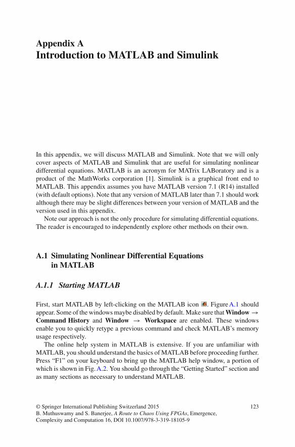
First, start MATLAB by left-clicking on the MATLAB icon . FigureA.1 shouldappear. Some of the windowsmaybe disabled by default.Make sure thatWindow →Command History and Window → Workspace are enabled. These windowsenable you to quickly retype a previous command and check MATLAB’s memoryusage respectively.
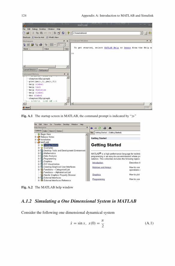
The online help system in MATLAB is extensive. If you are unfamiliar withMATLAB, you should understand the basics ofMATLAB before proceeding further.Press “F1” on your keyboard to bring up the MATLAB help window, a portion ofwhich is shown in Fig.A.2. You should go through the “Getting Started” section andas many sections as necessary to understand MATLAB.
© Springer International Publishing Switzerland 2015B. Muthuswamy and S. Banerjee, A Route to Chaos Using FPGAs, Emergence,Complexity and Computation 16, DOI 10.1007/978-3-319-18105-9
123
124 Appendix A: Introduction to MATLAB and Simulink
Fig. A.1 The startup screen in MATLAB, the command prompt is indicated by “�”
Fig. A.2 The MATLAB help window
A.1.2 Simulating a One Dimensional System in MATLAB
Consider the following one dimensional dynamical system
x = sin x, x(0) = π
2(A.1)
Appendix A: Introduction to MATLAB and Simulink 125
The code required to simulate the system is shown below. The MATLAB commentsshould make the code self-explanatory. Note that you should liberally comment yourcode to improve readability. While labeling the plot of our solution, we have usedMATLAB’s ability to interpret LATEX commands for improved readability. For moreinformation, type “help latex” at the MATLAB command prompt.
1 % Lines starting with a % are comment.2 % MATLAB code for simulating a one dimensional nonlinear3 % dynamical system4 % Muthuswamy, Bharathwaj56 % The lines below instruct MATLAB to clear all workspace variables7 % (or memory). It is a good idea to start your simulation from a8 % clean MATLAB state in order to eliminate the side-effects caused9 % by unused variables. The semicolon at the end of a line10 % supresses echo to the MATLAB command line.11 clear all;12 close all;1314 % The line below defines our system via the "inline" MATLAB15 % command. The first argument is our system. The second16 % argument defines the independent variable (time) and the17 % third argument defines the array "y" for our dependent18 % variable. Thus y(1) = x(t).19 sinusoidalSystem = inline('[sin(y(1))]','t','y');2021 % We setup tolerance options for the Ordinary Differential22 % Equation (ODE) solver.23 % The values below suffice for our systems.24 options = odeset('RelTol',1e-7,'AbsTol',1e-7);2526 % The line below invokes the medium order ode45 solver,27 % we will use this solver for our systems. The first argument28 % is the system to be solved.29 % The second argument is a matrix with start and stop times.30 % The third argument specifies the initial conditions and31 % the fourth argument uses the options specified previously.32 [t,ya] = ode45(sinusoidalSystem,[0,100],[pi/2],options);3334 % plot the solution. The first argument to the plot35 % command is the x-axis variable and the second argument36 % is the y-axis variable.37 plot(t,ya(:,1));3839 % Label axis with units. Then title the plot.40 % Note that we use a Latex interpreter.41 xlabel('$t$ (seconds)','FontSize',14,'Interpreter','Latex');42 ylabel('$x(t)$','FontSize',14,'Interpreter','Latex');43 title('Solution of $\dot{x} = \sin(x),x(0)=\frac{\pi}{2}$','Interpreter','Latex');
The reader is encouraged to use script files (or M-files in MATLAB terminology)to enter your commands so you can save them for reuse in a later MATLAB session.To create anM-file and enter the commands above, go to File → New → M − File.Enter the commands above and save the file as “oneDimensionalSimulation.m”. Theresult is shown inFig.A.3.You can run the file by typing the filename in theMATLABcommand prompt and pressing enter.

126 Appendix A: Introduction to MATLAB and Simulink
Fig. A.3 The result of simulating our one dimensional system
We have already seen how to simulate a chaotic system in MATLAB (the Lorenzsystem in Chap.1). Let us now understand how to use Simulink, the graphical front-end to MATLAB.
A.2 Simulating Nonlinear Differential Equationsin Simulink
In this section, we will show you how to simulate nonlinear differential equationsusing Simulink. This tool offers a more visual approach to the differential equationsetup.
A.2.1 Starting Simulink
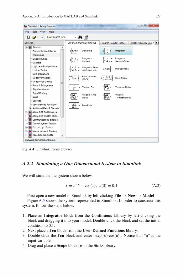
First, start Simulink by left-clicking on the Simulink iconin the MATLAB tool bar. FigureA.4 should pop up.
The Simulink library browser contains a plethora of components. We will restrictourselves to the Integrator block (highlighted in Fig.A.4) under the ContinuousLibrary and various blocks in the Math Operations, User-Defined Functions,Sinks and Sources library.
Appendix A: Introduction to MATLAB and Simulink 127
Fig. A.4 Simulink library browser
A.2.2 Simulating a One Dimensional System in Simulink
We will simulate the system shown below.
x = e−x − cos(x), x(0) = 0.1 (A.2)
First open a new model in Simulink by left-clicking File → New → ModelFigureA.5 shows the system represented in Simulink. In order to construct this
system, follow the steps below.
1. Place an Integrator block from the Continuous Library by left-clicking theblock and dragging it into your model. Double-click the block and set the initialcondition to 0.1.
2. Next place a Fcn block from the User-Defined Functions library.3. Double-click the Fcn block and enter “exp(-u)-cos(u)”. Notice that “u” is the
input variable.4. Drag and place a Scope block from the Sinks library.

128 Appendix A: Introduction to MATLAB and Simulink
Fig. A.5 The one dimensional system x = e−x − cos(x), x(0) = 0.1 in Simulink
5. Connect all the components as shown in Fig.A.5 by left-clicking and dragging awire connection.
6. Double-click anywhere in the model to add comments. Make sure you add acomment indicating the system you are simulating and also label wires, as shownin Fig.A.5.
To simulate the system, left-click the Play button in the Simulinktoolbar. The default options are sufficient for themodels in this book.You can increasethe simulation time appropriately, for this differential equation, 10 s is sufficient.
Fig. A.6 Result of simulating our system
Appendix A: Introduction to MATLAB and Simulink 129
The result should be Fig.A.6. Note that you cannot unfortunately name the axesand title the plot. The colors have been inverted for printing purposes.
A.2.3 Simulating a Chaotic System in Simulink
Now we will simulate the Sprott system shown below.
...x + x + x + f (x) = 0 (A.3)
The nonlinear function is given by:
f (x) = sign(1 + 4x) (A.4)
Here sign(x) is the signum function given by:
sign(x) =⎧⎨
⎩
−1 when x < 0,0 when x = 0,1 when x > 0.
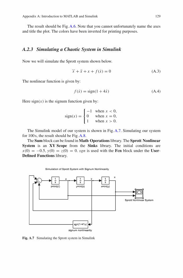
The Simulink model of our system is shown in Fig.A.7. Simulating our systemfor 100s, the result should be Fig.A.8.
The Sum block can be found inMath Operations library. The Sprott NonlinearSystem is an XY Scope from the Sinks library. The initial conditions arex(0) = −0.5, y(0) = z(0) = 0. sgn is used with the Fcn block under the User-Defined Functions library.
Fig. A.7 Simulating the Sprott system in Simulink

130 Appendix A: Introduction to MATLAB and Simulink
Fig. A.8 Results of simulating the Sprott system
A.3 Conclusion
In this appendix we showed you how to simulate nonlinear differential equations inMATLAB and Simulink.
The reader may have noticed that we are simulating a sensitive system on a finitestate machine (computer). How can we be even confident that our simulation iscorrect? It turns out that the concept of “shadowing” can be used to justify numericalsimulation of chaotic systems.1 For more information, please refer to the upcomingvolume II on theoretical methods.
Reference
1. The Mathworks Corporation (2012) Available via DIALOG. http://www.mathworks.com.Accessed 25 Dec 2012
1We cannot invoke the Nyquist-Shannon sampling theorem to determine a sampling frequencysince our system is not bandlimited.

Appendix BChapter 1 MATLAB Code
B.1 The Lorenz System
Listing B.1 MATLAB code for Lorenz equations1 % Lines starting with % are comments in MATLAB.2 % Extensively comment your code!3 % Purpose of this code: Obtaining phase plots and time-domain4 % waveforms for Lorenz system.5 %6 % The lines below instruct MATLAB to clear all workspace7 % variables (or memory). It is a good idea to start your8 % simulation from a clean MATLAB state in order to eliminate9 % the side-effects caused by unused variables. The semicolon
10 % at the end of a line will supress echo to the MATLAB command11 % line.12 clear all;13 close all;1415 % The line below defines our system via the "inline" MATLAB16 % command. The first argument is our system. Since our system17 % is three dimensional, we have a 3 x 1 matrix for our system.18 % The second argument defines the independent variable (time)19 % and the third argument defines the array "y" for our
dependent20 % variable. Thus y(1) = x(t),y(2) = y(t) and y(3) = z(t).21 lorenz = inline('[-10*y(1)+10*y(2);-y(1)*y(3)+28*y(1)-y(2);y
(1)*y(2)-(8/3)*y(3)]','t','y');2223 % We setup tolerance options for the Ordinary Differential24 % Equation (ODE) solver. The values below suffice for our25 % systems.26 options = odeset('RelTol',1e-7,'AbsTol',1e-7);2728 % The line below invokes the medium order ode45 solver, we
will
© Springer International Publishing Switzerland 2015B. Muthuswamy and S. Banerjee, A Route to Chaos Using FPGAs, Emergence,Complexity and Computation 16, DOI 10.1007/978-3-319-18105-9
131
132 Appendix B: Chapter 1 MATLAB Code
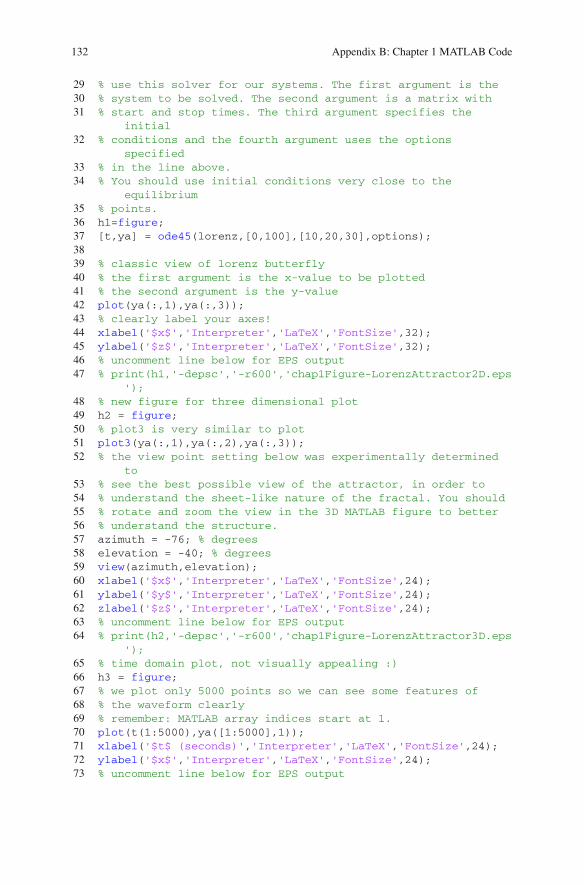
29 % use this solver for our systems. The first argument is the30 % system to be solved. The second argument is a matrix with31 % start and stop times. The third argument specifies the
initial32 % conditions and the fourth argument uses the options
specified33 % in the line above.34 % You should use initial conditions very close to the
equilibrium35 % points.36 h1=figure;37 [t,ya] = ode45(lorenz,[0,100],[10,20,30],options);3839 % classic view of lorenz butterfly40 % the first argument is the x-value to be plotted41 % the second argument is the y-value42 plot(ya(:,1),ya(:,3));43 % clearly label your axes!44 xlabel('$x$','Interpreter','LaTeX','FontSize',32);45 ylabel('$z$','Interpreter','LaTeX','FontSize',32);46 % uncomment line below for EPS output47 % print(h1,'-depsc','-r600','chap1Figure-LorenzAttractor2D.eps
');48 % new figure for three dimensional plot49 h2 = figure;50 % plot3 is very similar to plot51 plot3(ya(:,1),ya(:,2),ya(:,3));52 % the view point setting below was experimentally determined
to53 % see the best possible view of the attractor, in order to54 % understand the sheet-like nature of the fractal. You should55 % rotate and zoom the view in the 3D MATLAB figure to better56 % understand the structure.57 azimuth = -76; % degrees58 elevation = -40; % degrees59 view(azimuth,elevation);60 xlabel('$x$','Interpreter','LaTeX','FontSize',24);61 ylabel('$y$','Interpreter','LaTeX','FontSize',24);62 zlabel('$z$','Interpreter','LaTeX','FontSize',24);63 % uncomment line below for EPS output64 % print(h2,'-depsc','-r600','chap1Figure-LorenzAttractor3D.eps
');65 % time domain plot, not visually appealing :)66 h3 = figure;67 % we plot only 5000 points so we can see some features of68 % the waveform clearly69 % remember: MATLAB array indices start at 1.70 plot(t(1:5000),ya([1:5000],1));71 xlabel('$t$ (seconds)','Interpreter','LaTeX','FontSize',24);72 ylabel('$x$','Interpreter','LaTeX','FontSize',24);73 % uncomment line below for EPS output
Appendix B: Chapter 1 MATLAB Code 133
74 % print(h3,'-depsc','-r600','chap1Figure-LorenzAttractorTimeDomain.eps');
B.2 Linear Equation
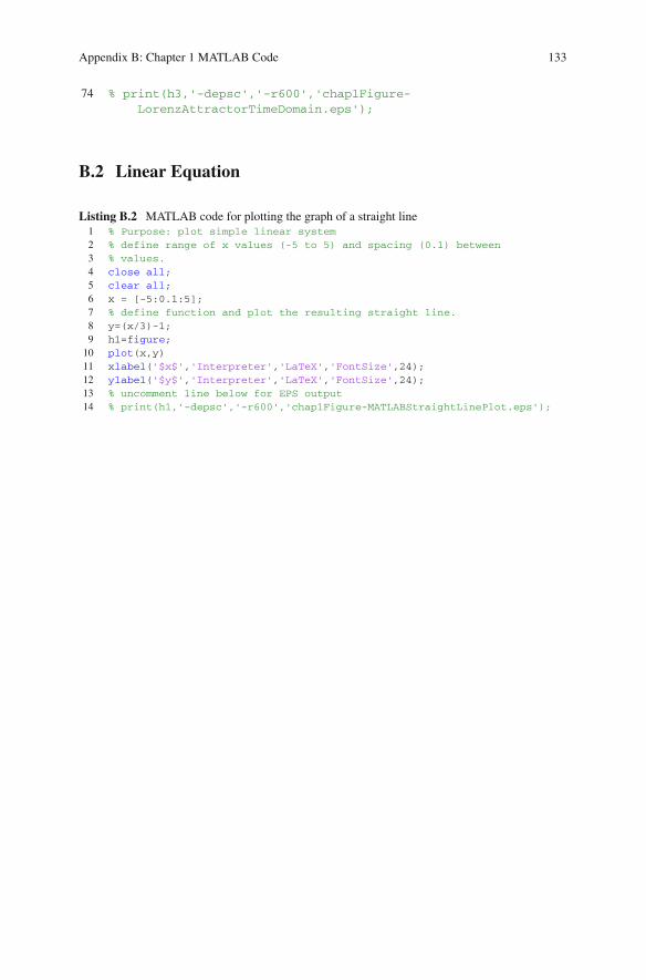
Listing B.2 MATLAB code for plotting the graph of a straight line1 % Purpose: plot simple linear system2 % define range of x values (-5 to 5) and spacing (0.1) between3 % values.4 close all;5 clear all;6 x = [-5:0.1:5];7 % define function and plot the resulting straight line.8 y=(x/3)-1;9 h1=figure;10 plot(x,y)11 xlabel('$x$','Interpreter','LaTeX','FontSize',24);12 ylabel('$y$','Interpreter','LaTeX','FontSize',24);13 % uncomment line below for EPS output14 % print(h1,'-depsc','-r600','chap1Figure-MATLABStraightLinePlot.eps');
Appendix CChapter 2 VHDL, Simulink DSP Builderand SDC File
C.1 VHDL Generic Full Adder
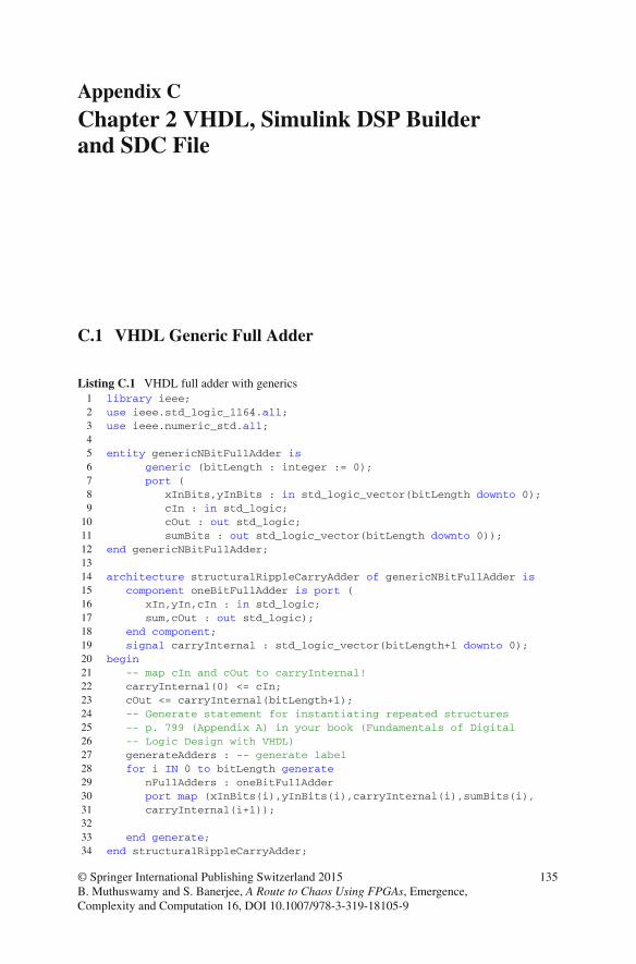
Listing C.1 VHDL full adder with generics1 library ieee;2 use ieee.std_logic_1164.all;3 use ieee.numeric_std.all;45 entity genericNBitFullAdder is6 generic (bitLength : integer := 0);7 port (8 xInBits,yInBits : in std_logic_vector(bitLength downto 0);9 cIn : in std_logic;
10 cOut : out std_logic;11 sumBits : out std_logic_vector(bitLength downto 0));12 end genericNBitFullAdder;1314 architecture structuralRippleCarryAdder of genericNBitFullAdder is15 component oneBitFullAdder is port (16 xIn,yIn,cIn : in std_logic;17 sum,cOut : out std_logic);18 end component;19 signal carryInternal : std_logic_vector(bitLength+1 downto 0);20 begin21 -- map cIn and cOut to carryInternal!22 carryInternal(0) <= cIn;23 cOut <= carryInternal(bitLength+1);24 -- Generate statement for instantiating repeated structures25 -- p. 799 (Appendix A) in your book (Fundamentals of Digital26 -- Logic Design with VHDL)27 generateAdders : -- generate label28 for i IN 0 to bitLength generate29 nFullAdders : oneBitFullAdder30 port map (xInBits(i),yInBits(i),carryInternal(i),sumBits(i),31 carryInternal(i+1));3233 end generate;34 end structuralRippleCarryAdder;
© Springer International Publishing Switzerland 2015B. Muthuswamy and S. Banerjee, A Route to Chaos Using FPGAs, Emergence,Complexity and Computation 16, DOI 10.1007/978-3-319-18105-9
135

136 Appendix C: Chapter 2 VHDL, Simulink DSP Builder and SDC File
Points to note from the VHDL description are:
1. In line 6 we have utilized the generic keyword to emphasize that, the size ofthe full adder can be resolved only at synthesis time.
2. Line 19 declares internal carry signals that will be utilized to interconnect thecarry inputs and outputs of the one bit adders.
3. Lines 22 and 23map the input carry to the least significant bit of the internal carrysignal and the output carry to the most significant bit of the internal carry signal.
4. Lines 27–31 implement parameterization in VHDL via the for loop construct.Note that you need to make sure the VHDL syntax is correct, we have addedcarriage returns for code clarity.
C.2 VHDL Seven Segment Decoder
Listing C.2 VHDL behavioural seven segment decoder1 library ieee;2 use ieee.std_logic_1164.all;3 use ieee.numeric_std.all;45 entity sevenSegmentDecoder is port (6 integerIn : in integer range 0 to 9;7 hexOut : out std_logic_vector(7 downto 0));8 end sevenSegmentDecoder;910 architecture behavioral of sevenSegmentDecoder is11 begin12 with integerIn select13 hexOut <= X"40" when 0,14 X"79" when 1,15 X"24" when 2,16 X"30" when 3,17 X"19" when 4,18 X"12" when 5,19 X"02" when 6,20 X"78" when 7,21 X"00" when 8,22 X"10" when others;23 end behavioral;

Appendix C: Chapter 2 VHDL, Simulink DSP Builder and SDC File 137
C.3 Top-Level for Generic Full Adder
Listing C.3 VHDL top level for generic adder1 library ieee;2 use ieee.std_logic_1164.all;3 use ieee.numeric_std.all;45 entity rippleCarryAdder is port (6 SW : in std_logic_vector(9 downto 0);7 HEX3,HEX2,HEX1,HEX0 : out std_logic_vector(6 downto 0);8 -- LEDs are going to indicate carry out9 LEDG : out std_logic_vector(7 downto 0));10 end rippleCarryAdder;1112 architecture topLevel of rippleCarryAdder is1314 component genericNBitFullAdder is15 generic (bitLength : integer := 0);16 port (17 xInBits,yInBits : in std_logic_vector(bitLength
downto 0);18 cIn : in std_logic;19 cOut : out std_logic;20 sumBits : out std_logic_vector(bitLength downto 0));21 end component;2223 component sevenSegmentDecoder is port (24 integerIn : in integer range 0 to 9;25 hexOut : out std_logic_vector(7 downto 0));26 end component;2728 signal carry0 : std_logic;29 signal sumInternal : std_logic_vector(3 downto 0);30 signal sumInteger : integer;31 signal unitsDigit,tensDigit : integer;32 signal hex0Out,hex1Out : std_logic_vector(7 downto 0);3334 begin35 carry0 <= '0';36 oneBitFullAdder : genericNBitFullAdder generic map37 (bitLength => 0)38 port map ( xInBits => SW(0 downto 0),39 yInBits => SW(1 downto 1),40 cIn => carry0,41 cOut => LEDG(0),42 sumBits => LEDG(1 downto 1));43 fourBitFullAdder : genericNBitFullAdder generic map44 (bitLength => 3)45 port map ( xInBits => SW(5 downto 2),46 yInBits => SW(9 downto 6),
138 Appendix C: Chapter 2 VHDL, Simulink DSP Builder and SDC File
47 cIn => carry0,48 cOut => LEDG(2),49 sumBits => sumInternal(3 downto 0));5051 sumInteger <= to_integer(unsigned(sumInternal));52 unitsDigit <= sumInteger rem 10;53 tensDigit <= sumInteger / 10;5455 unitsDisplay : sevenSegmentDecoder port map (unitsDigit,
hex0Out);56 tensDisplay : sevenSegmentDecoder port map (tensDigit,
hex1Out);57 HEX0 <= hex0Out(6 downto 0);58 HEX1 <= hex1Out(6 downto 0);5960 end topLevel;
1. Lines 36–47 show that we are going to realize two adders : an one bit full adderand a four bit full adder. The important VHDL syntax nuance is: since the gener-icNBitFullAdder module expects a std_logic_vector, we need to make sure ourone bit inputs and outputs are of type std_logic_vector, not of type std_logic.Hence, instead of using SW(0) we use SW(0 down to 0).
2. Lines 49–51 convert the output from the four bit full adder into an unsigned integerand thedigits from the integer are extracted for usewith the sevenSegmentDecodermodule. The online reference design video for theALU realization in Sect. 2.3.2.2has details on extracting digits from unsigned integers.
C.4 Seconds Counter with Single Pulse Generator
Listing C.4 VHDL seconds counter1 library ieee;2 use ieee.std_logic_1164.all;3 use ieee.numeric_std.all;45 entity secondsCounter is port (6 areset,clockIn : in std_logic;7 minuteCounterEnablePulse : out std_logic;8 secondsOut : out integer range 0 to 59);9 end entity;1011 architecture behavioralSecondsCounter of secondsCounter is1213 type state is (reset,generatePulse,stop);14 signal currentState,nextState : state;1516 signal secondsCountRegister : integer range 0 to 49999999;17 signal internalSecondsCount : integer range 0 to 59;18 signal enablePulseGenerator : std_logic;19 --
Appendix C: Chapter 2 VHDL, Simulink DSP Builder and SDC File 139
20 begin2122 secondsCountProcess : process(areset,clockIn)23 begin24 if areset='1' then25 secondsCountRegister <= 0;26 internalSecondsCount <= 0;27 enablePulseGenerator <= '0';28 else29 if rising_edge(clockIn) then30 if secondsCountRegister >= 49999 then31 secondsCountRegister <= 0;32 if internalSecondsCount >= 59 then33 internalSecondsCount <= 0;34 enablePulseGenerator <= '1';35 else36 internalSecondsCount <=
internalSecondsCount + 1;37 enablePulseGenerator <= '0';38 end if;39 else40 secondsCountRegister <= secondsCountRegister
+1;41 end if;4243 end if;44 end if;45 end process;4647 -- single pulse generator state machine48 stateMemory : process(areset,clockIn)49 begin50 if areset='1' then51 currentState <= reset;52 else53 if rising_edge(clockIn) then54 currentState <= nextState;55 end if;56 end if;57 end process;58 stateTransitionLogic : process(enablePulseGenerator,
currentState)59 begin60 case currentState is61 when reset =>62 if enablePulseGenerator='1' then63 nextState <= generatePulse;64 else65 nextState <= reset;66 end if;67 when generatePulse =>68 nextState <= stop;69 when others =>
140 Appendix C: Chapter 2 VHDL, Simulink DSP Builder and SDC File
70 if enablePulseGenerator='0' then71 nextState <= reset;72 else73 nextState <= stop;74 end if;75 end case;76 end process;77 -- output logic (could put this inside state transition
logic process)78 with currentState select79 minuteCounterEnablePulse <= '1' when generatePulse,80 '0' when others;81 -- end single pulse generator FSM8283 --output seconds count register content for display84 secondsOut <= internalSecondsCount;8586 end behavioralSecondsCounter;
Themain ideas in the snippet that correspond to each of the blocks in Fig. 2.15 are:
1. Lines 13 and 14 illustrate how to use the type specification in VHDL to specifyuser-defined states. This will help the synthesizer (and simulator) infer a statemachine from your design.
2. Lines 48–57 will infer the state memory block in Fig. 2.15.3. Lines 58–76 will infer the next state logic block in Fig. 2.15.4. Line 78 will infer the output logic block in Fig. 2.15.
C.5 Abstracting the FPGA Development Flow in Simulink
Simulink should be the tool of choice in realizing abstract mathematical concepts.For realizing chaotic system nonlinearities, we will utilize DSP builder blocksetfor Simulink from Altera. The reference for this section is Altera’s DSP BuilderAdvanced Blockset reference manual that can be found on Altera’s DSP Builderwebsite [1].
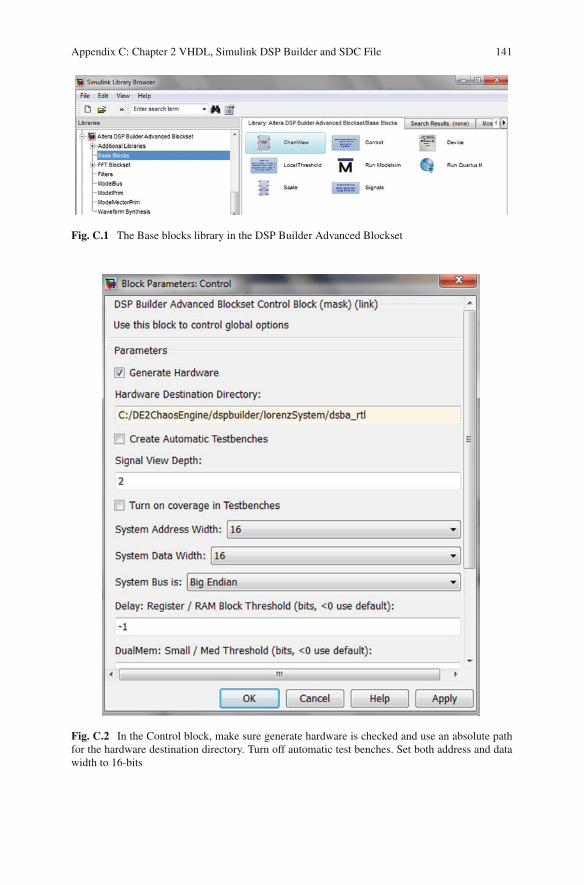
1. The concept behind DSP builder is to create a synthesizable subsystem that incor-porates our mathematical abstraction. To do so, we first access the Altera DSPBuilder Advanced Blockset2 library from Simulink, as shown in Fig.C.1.
2. We create a new Simulink model and then place the Control and Signals blockfrom the Base Blocks library in Fig.C.1. FiguresC.2 and C.3 show the configu-ration parameters for these blocks that will be used in a majority of the designsin this book.
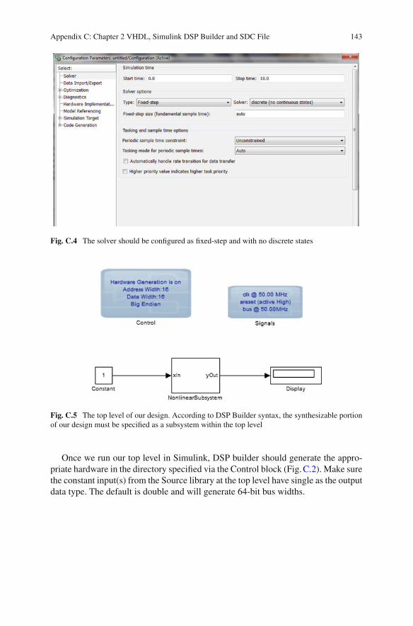
3. We next set the solver configurations as shown in Fig.C.4. The completed toplevel is shown in Fig.C.5. We have created a subsystem at the top level. Withinthis subsystem, we will realize the nonlinear synthesizable subsystem.
2Altera recommends the use of Advanced Blockset instead of Standard Blockset for newer designs.
Appendix C: Chapter 2 VHDL, Simulink DSP Builder and SDC File 141
Fig. C.1 The Base blocks library in the DSP Builder Advanced Blockset
Fig. C.2 In the Control block, make sure generate hardware is checked and use an absolute pathfor the hardware destination directory. Turn off automatic test benches. Set both address and datawidth to 16-bits
142 Appendix C: Chapter 2 VHDL, Simulink DSP Builder and SDC File
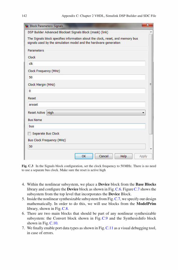
Fig. C.3 In the Signals block configuration, set the clock frequency to 50MHz. There is no needto use a separate bus clock. Make sure the reset is active high
4. Within the nonlinear subsystem, we place a Device block from the Base Blockslibrary and configure the Device block as shown in Fig.C.6. FigureC.7 shows thesubsystem from the top level that incorporates the Device Block.
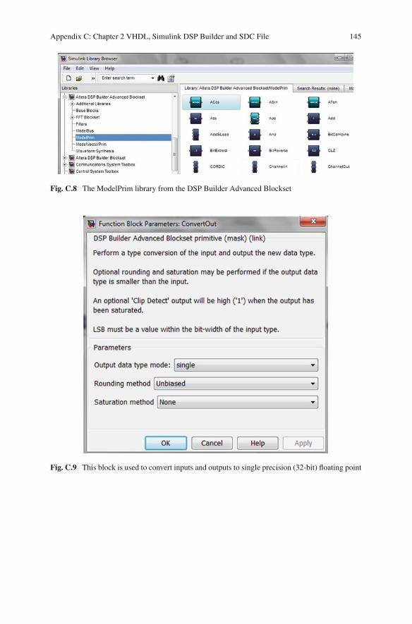
5. Inside the nonlinear synthesizable subsystem fromFig.C.7, we specify our designmathematically. In order to do this, we will use blocks from the ModelPrimlibrary, shown in Fig.C.8.
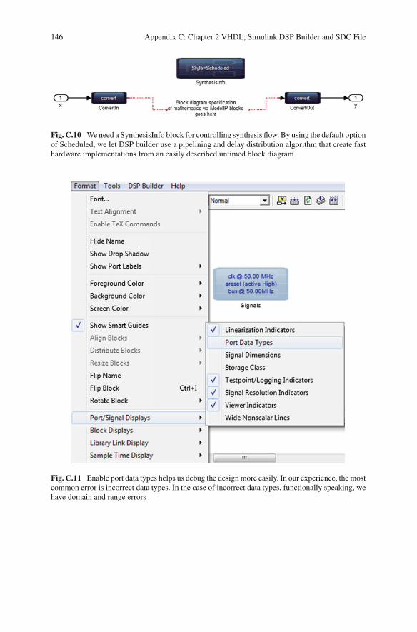
6. There are two main blocks that should be part of any nonlinear synthesizablesubsystem: the Convert block shown in Fig.C.9 and the SynthesisInfo blockshown in Fig.C.10.
7. We finally enable port data types as shown in Fig.C.11 as a visual debugging tool,in case of errors.
Appendix C: Chapter 2 VHDL, Simulink DSP Builder and SDC File 143
Fig. C.4 The solver should be configured as fixed-step and with no discrete states
Fig. C.5 The top level of our design. According to DSP Builder syntax, the synthesizable portionof our design must be specified as a subsystem within the top level
Once we run our top level in Simulink, DSP builder should generate the appro-priate hardware in the directory specified via the Control block (Fig.C.2). Make surethe constant input(s) from the Source library at the top level have single as the outputdata type. The default is double and will generate 64-bit bus widths.

144 Appendix C: Chapter 2 VHDL, Simulink DSP Builder and SDC File
Fig. C.6 Device block configuration. We don’t have to explicitly set the Cyclone IV E part numbersince we are only going to be synthesizing a subsystem, not a stand-alone Quartus project fromDSP Builder
Fig. C.7 The Device block must be placed within a subsystem, not at the top level that has theControl and Signals blocks
Appendix C: Chapter 2 VHDL, Simulink DSP Builder and SDC File 145
Fig. C.8 The ModelPrim library from the DSP Builder Advanced Blockset
Fig. C.9 This block is used to convert inputs and outputs to single precision (32-bit) floating point
146 Appendix C: Chapter 2 VHDL, Simulink DSP Builder and SDC File
Fig. C.10 Weneed a SynthesisInfo block for controlling synthesis flow. By using the default optionof Scheduled, we let DSP builder use a pipelining and delay distribution algorithm that create fasthardware implementations from an easily described untimed block diagram
Fig. C.11 Enable port data types helps us debug the design more easily. In our experience, the mostcommon error is incorrect data types. In the case of incorrect data types, functionally speaking, wehave domain and range errors

Appendix C: Chapter 2 VHDL, Simulink DSP Builder and SDC File 147
C.6 SDC File for Twenty Four Hour Clock Design
Listing C.5 Synopsys Design Constraint File1 # STEP 1: ADD CLOCK CONSTRAINTS2 # the constraint below assigns a 20 ns clock to the input
port3 # CLOCK_50. Note that we use the default name (CLOCK_50)4 # as the name of the clock. This is our board clock.5 create_clock -name CLOCK_50 -period 20.00067 # There are no virtual I/O clocks since we are not driving8 # external devices. Moreover, because we have a SINGLE9 # clock for our entire design, virtual clocks are un-
necessary.1011 # take care of PLL clocking constraints automatically.12 # Note that this is an Altera SDC extension and this may not13 # be available from all FPGA vendors. The create_base_clocks14 # flag below generates create_clock constraints for PLL input15 # clocks16 derive_pll_clocks -create_base_clocks1718 # the command below automatically derives clock
uncertainities19 # such as setup, hold etc. Results only seen after place and
route.20 derive_clock_uncertainty2122 # Note that since we have a globally synchronous design23 # (all flip-flops are being driven by the SAME PLL clock),24 # we are DONE with clocking constraints!25 # Once are done with clocking constraints, run TimeQuest26 # to make sure clocks are constrainted.2728 # STEP 2: Add I/O constraints. We will add output constraints29 # to the hex displays since these are actually registered
outputs,30 # with the global 50 MHz clock.31 # The input and output delays really don't matter for this
example.32 # Of course, if our design is driving timing critical
external logic,33 # then the board clock skew etc. need to be accurate.34 set_output_delay -clock { CLOCK_50 } -max 5 [get_ports {HEX
*}]35 set_output_delay -clock { CLOCK_50 } -min 10 [get_ports {HEX
*}]3637 # STEP 3: Asynchronous path(s). Since the external KEY(0)
input38 # is truly asynchronous, we have internally synchronized the
reset.

148 Appendix C: Chapter 2 VHDL, Simulink DSP Builder and SDC File
39 # Hence, we can safely apply a false path constraint.40 set_false_path -from [get_ports KEY*]
Reference
1. Altera Corporation (2013) DSPBuilder, Available via DIALOG. http://www.altera.com/products/software/products/dsp/dsp-builder.html. Accessed 7 May 2013

Appendix DChapter 3 VHDL, MATLAB Codeand ModelSim Scripts
D.1 VHDL Specification of the Lorenz System
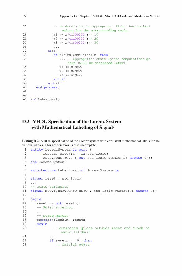
Listing D.1 VHDL specification of the Lorenz system. We have split comments over multiplelines so be careful when copying and pasting the HDL! Note that the specification is incomplete,we use it to understand the ideas behind Euler’s method1 entity lorenzSystem is port (2 resetn, clockIn : in std_logic;3 xOut,yOut,zOut : out std_logic_vector(15 downto 0));4 end lorenzSystem;56 architecture behavioral of lorenzSystem is78 signal reset : std_logic;9 ...
10 -- state variables11 signal x1,x2,x3,x1New,x2New,x3New : std_logic_vector (31 downto 0)
;12 ...13 begin14 reset <= not resetn;15 -- Euler's method16 ...17 -- state memory18 process(clockIn, resetn)19 begin20 -- constants (place outside reset and clock to avoid
latches)21 ...22 if resetn = '0' then23 -- initial state24 -- the constants below are in single-precision 32-bit
floating point format25 -- You can use an online floating point converter such
as :26 -- http://babbage.cs.qc.cuny.edu/IEEE-754.old/Decimal.
html
© Springer International Publishing Switzerland 2015B. Muthuswamy and S. Banerjee, A Route to Chaos Using FPGAs, Emergence,Complexity and Computation 16, DOI 10.1007/978-3-319-18105-9
149
150 Appendix D: Chapter 3 VHDL, MATLAB Code and ModelSim Scripts
27 -- to determine the appropriate 32-bit hexadecimalvalues for the corresponding reals.
28 x1 <= X"41200000";-- 1029 x2 <= X"41A00000";-- 2030 x3 <= X"41F00000";-- 3031 ...32 else33 if rising_edge(clockIn) then34 ... -- appropriate state update computations go
here (will be discussed later)35 x1 <= x1New;36 x2 <= x2New;37 x3 <= x3New;38 end if;39 end if;40 end process;41 ...42 ...43 end behavioral;
D.2 VHDL Specification of the Lorenz Systemwith Mathematical Labelling of Signals
Listing D.2 VHDL specification of the Lorenz system with consistent mathematical labels for thevarious signals. This specification is also incomplete1 entity lorenzSystem is port (2 resetn, clockIn : in std_logic;3 xOut,yOut,zOut : out std_logic_vector(15 downto 0));4 end lorenzSystem;56 architecture behavioral of lorenzSystem is78 signal reset : std_logic;9 ...10 -- state variables11 signal x,y,z,xNew,yNew,zNew : std_logic_vector(31 downto 0);12 ...13 begin14 reset <= not resetn;15 -- Euler's method16 ...17 -- state memory18 process(clockIn, resetn)19 begin20 -- constants (place outside reset and clock to
avoid latches)21 ...22 if resetn = '0' then23 -- initial state
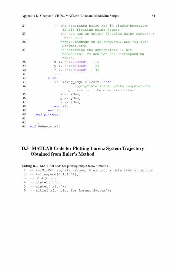
Appendix D: Chapter 3 VHDL, MATLAB Code and ModelSim Scripts 151
24 -- the constants below are in single-precision32-bit floating point format
25 -- You can use an online floating point convertersuch as :
26 -- http://babbage.cs.qc.cuny.edu/IEEE-754.old/Decimal.html
27 -- to determine the appropriate 32-bithexadecimal values for the correspondingreals.
28 x <= X"41200000";-- 1029 y <= X"41A00000";-- 2030 z <= X"41F00000";-- 3031 ...32 else33 if rising_edge(clockIn) then34 ... -- appropriate state update computations
go here (will be discussed later)35 x <= xNew;36 y <= yNew;37 z <= zNew;38 end if;39 end if;40 end process;41 ...42 ...43 end behavioral;
D.3 MATLAB Code for Plotting Lorenz System TrajectoryObtained from Euler’s Method
Listing D.3 MATLAB code for plotting output from Simulink1 >> x=xSimOut.signals.values; % extract x data from structure2 >> t=linspace(0,1,1001);3 >> plot(t,x')4 >> xlabel('t');5 >> ylabel('x(t)');6 >> title('x(t) plot for Lorenz System');
152 Appendix D: Chapter 3 VHDL, MATLAB Code and ModelSim Scripts
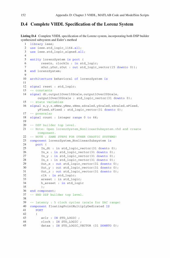
D.4 Complete VHDL Specification of the Lorenz System
Listing D.4 Complete VHDL specification of the Lorenz system, incorporating both DSP buildersynthesized subsystem and Euler’s method
1 library ieee;2 use ieee.std_logic_1164.all;3 use ieee.std_logic_signed.all;45 entity lorenzSystem is port (6 resetn, clockIn : in std_logic;7 xOut,yOut,zOut : out std_logic_vector(15 downto 0));8 end lorenzSystem;9
10 architecture behavioral of lorenzSystem is1112 signal reset : std_logic;13 -- constants14 signal dt,output1Over10Scale,output1Over20Scale,
output1Over30Scale : std_logic_vector(31 downto 0);15 -- state variables16 signal x,y,z,xNew,yNew,zNew,xScaled,yScaled,zScaled,xFixed,
yFixed,zFixed : std_logic_vector(31 downto 0);17 -- prescalar18 signal count : integer range 0 to 64;1920 -- DSP builder top level.21 -- Note: Open lorenzSystem_NonlinearSubsystem.vhd and create
component.22 -- NOTE : SAME STEPS FOR OTHER CHAOTIC SYSTEMS!23 component lorenzSystem_NonlinearSubsystem is24 port (25 In_dt : in std_logic_vector(31 downto 0);26 In_x : in std_logic_vector(31 downto 0);27 In_y : in std_logic_vector(31 downto 0);28 In_z : in std_logic_vector(31 downto 0);29 Out_x : out std_logic_vector(31 downto 0);30 Out_y : out std_logic_vector(31 downto 0);31 Out_z : out std_logic_vector(31 downto 0);32 clk : in std_logic;33 areset : in std_logic;34 h_areset : in std_logic35 );36 end component;37 -- END DSP builder top level.3839 -- latency : 5 clock cycles (scale for DAC range)40 component floatingPointMultiplyDedicated IS41 PORT42 (43 aclr : IN STD_LOGIC ;44 clock : IN STD_LOGIC ;45 dataa : IN STD_LOGIC_VECTOR (31 DOWNTO 0);
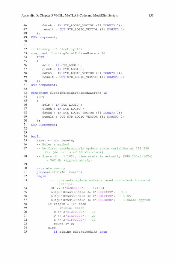
Appendix D: Chapter 3 VHDL, MATLAB Code and ModelSim Scripts 153
46 datab : IN STD_LOGIC_VECTOR (31 DOWNTO 0);47 result : OUT STD_LOGIC_VECTOR (31 DOWNTO 0)48 );49 END component;505152 -- latency : 6 clock cycles53 component floatingPointToFixedLorenz IS54 PORT55 (56 aclr : IN STD_LOGIC ;57 clock : IN STD_LOGIC ;58 dataa : IN STD_LOGIC_VECTOR (31 DOWNTO 0);59 result : OUT STD_LOGIC_VECTOR (31 DOWNTO 0)60 );61 END component;6263 component floatingPointToFixedZLorenz IS64 PORT65 (66 aclr : IN STD_LOGIC ;67 clock : IN STD_LOGIC ;68 dataa : IN STD_LOGIC_VECTOR (31 DOWNTO 0);69 result : OUT STD_LOGIC_VECTOR (31 DOWNTO 0)70 );71 END component;727374 begin75 reset <= not resetn;76 -- Euler's method77 -- We first synchronously update state variables at 781.250
KHz (64 counts of 50 MHz clock)78 -- Since dt = 1/1024, time scale is actually (780.250e3/1024)
= 762 Hz (approximately)7980 -- state memory81 process(clockIn, resetn)82 begin83 -- constants (place outside reset and clock to avoid
latches)84 dt <= X"3A800000"; -- 1/102485 output1Over10Scale <= X"3DCCCCCC"; --0.186 output1Over20Scale <= X"3D4CCCCC"; -- 0.0587 output1Over30Scale <= X"3D888888"; -- 0.06666 approx.88 if resetn = '0' then89 -- initial state90 x <= X"41200000";-- 1091 y <= X"41A00000";-- 2092 z <= X"41F00000";-- 3093 count <= 0;94 else95 if rising_edge(clockIn) then
154 Appendix D: Chapter 3 VHDL, MATLAB Code and ModelSim Scripts
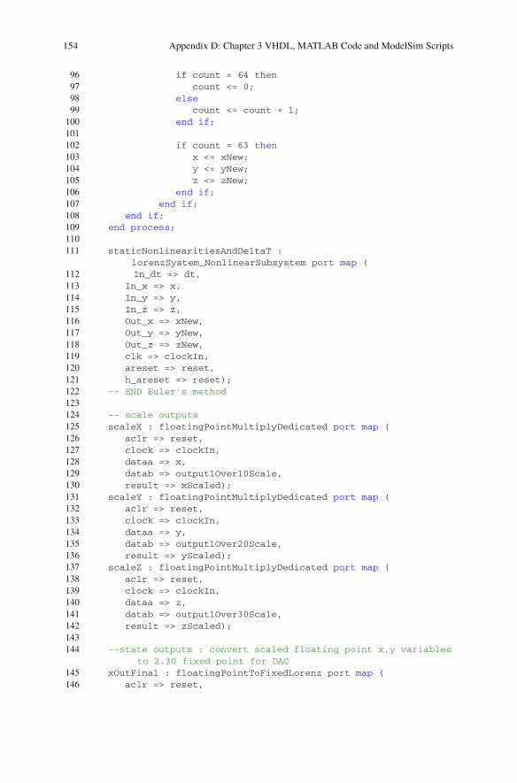
96 if count = 64 then97 count <= 0;98 else99 count <= count + 1;
100 end if;101102 if count = 63 then103 x <= xNew;104 y <= yNew;105 z <= zNew;106 end if;107 end if;108 end if;109 end process;110111 staticNonlinearitiesAndDeltaT :
lorenzSystem_NonlinearSubsystem port map (112 In_dt => dt,113 In_x => x,114 In_y => y,115 In_z => z,116 Out_x => xNew,117 Out_y => yNew,118 Out_z => zNew,119 clk => clockIn,120 areset => reset,121 h_areset => reset);122 -- END Euler's method123124 -- scale outputs125 scaleX : floatingPointMultiplyDedicated port map (126 aclr => reset,127 clock => clockIn,128 dataa => x,129 datab => output1Over10Scale,130 result => xScaled);131 scaleY : floatingPointMultiplyDedicated port map (132 aclr => reset,133 clock => clockIn,134 dataa => y,135 datab => output1Over20Scale,136 result => yScaled);137 scaleZ : floatingPointMultiplyDedicated port map (138 aclr => reset,139 clock => clockIn,140 dataa => z,141 datab => output1Over30Scale,142 result => zScaled);143144 --state outputs : convert scaled floating point x,y variables
to 2.30 fixed point for DAC145 xOutFinal : floatingPointToFixedLorenz port map (146 aclr => reset,
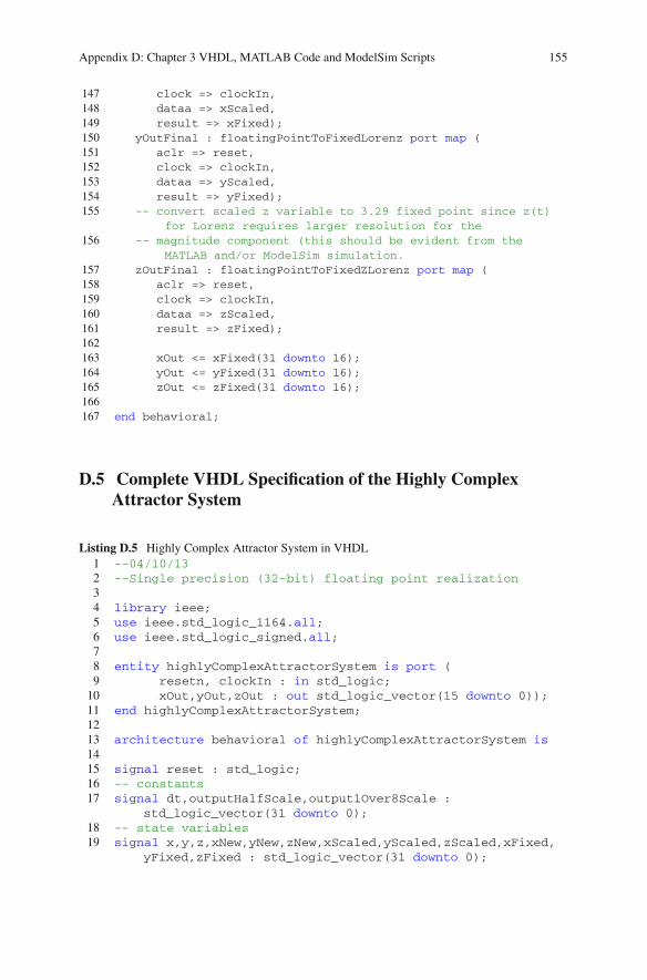
Appendix D: Chapter 3 VHDL, MATLAB Code and ModelSim Scripts 155
147 clock => clockIn,148 dataa => xScaled,149 result => xFixed);150 yOutFinal : floatingPointToFixedLorenz port map (151 aclr => reset,152 clock => clockIn,153 dataa => yScaled,154 result => yFixed);155 -- convert scaled z variable to 3.29 fixed point since z(t)
for Lorenz requires larger resolution for the156 -- magnitude component (this should be evident from the
MATLAB and/or ModelSim simulation.157 zOutFinal : floatingPointToFixedZLorenz port map (158 aclr => reset,159 clock => clockIn,160 dataa => zScaled,161 result => zFixed);162163 xOut <= xFixed(31 downto 16);164 yOut <= yFixed(31 downto 16);165 zOut <= zFixed(31 downto 16);166167 end behavioral;
D.5 Complete VHDL Specification of the Highly ComplexAttractor System
Listing D.5 Highly Complex Attractor System in VHDL1 --04/10/132 --Single precision (32-bit) floating point realization34 library ieee;5 use ieee.std_logic_1164.all;6 use ieee.std_logic_signed.all;78 entity highlyComplexAttractorSystem is port (9 resetn, clockIn : in std_logic;10 xOut,yOut,zOut : out std_logic_vector(15 downto 0));11 end highlyComplexAttractorSystem;1213 architecture behavioral of highlyComplexAttractorSystem is1415 signal reset : std_logic;16 -- constants17 signal dt,outputHalfScale,output1Over8Scale :
std_logic_vector(31 downto 0);18 -- state variables19 signal x,y,z,xNew,yNew,zNew,xScaled,yScaled,zScaled,xFixed,
yFixed,zFixed : std_logic_vector(31 downto 0);

156 Appendix D: Chapter 3 VHDL, MATLAB Code and ModelSim Scripts
20 -- prescalar21 signal count : integer range 0 to 64;2223 -- DSP builder top level. Steps to add:24 -- 1. source ./dspba_rtl/highlyComplexAttractor/
NonlinearSubsystem/NonlinearSubsystem.add.tcl via TCLwindow (View -> Utility Windows -> TCL Console)
25 -- 2. source ./dspba_rtl/highlyComplexAttractor/NonlinearSubsystem/highlyComplexAttractor_NonlinearSubsystem_fpc.add.tclvia TCL window (View -> Utility Windows -> TCL Console)
26 -- 2. Open highlyComplexAttractor_NonlinearSubsystem.vhdfrom the path above and create component.
27 -- NOTE : SAME STEPS FOR OTHER CHAOTIC SYSTEMS!28 component highlyComplexAttractor_NonlinearSubsystem is29 port (30 In_dt : in std_logic_vector(31 downto 0);31 In_x : in std_logic_vector(31 downto 0);32 In_y : in std_logic_vector(31 downto 0);33 In_z : in std_logic_vector(31 downto 0);34 Out_x : out std_logic_vector(31 downto 0);35 Out_y : out std_logic_vector(31 downto 0);36 Out_z : out std_logic_vector(31 downto 0);37 clk : in std_logic;38 areset : in std_logic;39 h_areset : in std_logic);40 end component;41 -- END DSP builder top level.4243 -- latency : 5 clock cycles (scale for DAC range)44 component floatingPointMultiplyDedicated IS45 PORT46 (47 aclr : IN STD_LOGIC ;48 clock : IN STD_LOGIC ;49 dataa : IN STD_LOGIC_VECTOR (31 DOWNTO 0);50 datab : IN STD_LOGIC_VECTOR (31 DOWNTO 0);51 result : OUT STD_LOGIC_VECTOR (31 DOWNTO 0)52 );53 END component;545556 -- latency : 6 clock cycles57 component floatingPointToFixed IS58 PORT59 (60 aclr : IN STD_LOGIC ;61 clock : IN STD_LOGIC ;62 dataa : IN STD_LOGIC_VECTOR (31 DOWNTO 0);63 result : OUT STD_LOGIC_VECTOR (31 DOWNTO 0)64 );65 END component;66
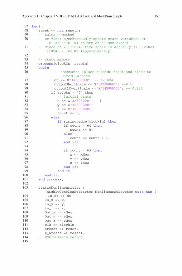
Appendix D: Chapter 3 VHDL, MATLAB Code and ModelSim Scripts 157
67 begin68 reset <= not resetn;69 -- Euler's method70 -- We first synchronously update state variables at
781.250 KHz (64 counts of 50 MHz clock)71 -- Since dt = 1/1024, time scale is actually (780.250e3
/1024) = 762 Hz (approximately)7273 -- state memory74 process(clockIn, resetn)75 begin76 -- constants (place outside reset and clock to
avoid latches)77 dt <= X"3A800000"; -- 1/102478 outputHalfScale <= X"3F000000"; --0.579 output1Over8Scale <= X"3E000000"; -- 0.12580 if resetn = '0' then81 -- initial state82 x <= X"3F800000";-- 183 y <= X"3F800000";84 z <= X"3F800000";85 count <= 0;86 else87 if rising_edge(clockIn) then88 if count = 64 then89 count <= 0;90 else91 count <= count + 1;92 end if;9394 if count = 63 then95 x <= xNew;96 y <= yNew;97 z <= zNew;98 end if;99 end if;
100 end if;101 end process;102103 staticNonlinearities :
highlyComplexAttractor_NonlinearSubsystem port map (104 In_dt => dt,105 In_x => x,106 In_y => y,107 In_z => z,108 Out_x => xNew,109 Out_y => yNew,110 Out_z => zNew,111 clk => clockIn,112 areset => reset,113 h_areset => reset);114 -- END Euler's method115

158 Appendix D: Chapter 3 VHDL, MATLAB Code and ModelSim Scripts
116 -- scale outputs117 scaleX : floatingPointMultiplyDedicated port map (118 aclr => reset,119 clock => clockIn,120 dataa => x,121 datab => outputHalfScale,122 result => xScaled);123 scaleY : floatingPointMultiplyDedicated port map (124 aclr => reset,125 clock => clockIn,126 dataa => y,127 datab => outputHalfScale,128 result => yScaled);129 scaleZ : floatingPointMultiplyDedicated port map (130 aclr => reset,131 clock => clockIn,132 dataa => z,133 datab => output1Over8Scale,134 result => zScaled);135136 --state outputs : convert scaled floating point variables
to 5.27 fixed point format DAC (no latency)137 xOutFinal : floatingPointToFixed port map (138 aclr => reset,139 clock => clockIn,140 dataa => xScaled,141 result => xFixed);142 yOutFinal : floatingPointToFixed port map (143 aclr => reset,144 clock => clockIn,145 dataa => yScaled,146 result => yFixed);147 zOutFinal : floatingPointToFixed port map (148 aclr => reset,149 clock => clockIn,150 dataa => zScaled,151 result => zFixed);152153 xOut <= xFixed(31 downto 16);154 yOut <= yFixed(31 downto 16);155 zOut <= zFixed(31 downto 16);156157 end behavioral;
D.6 VHDL Testbench for Chen System
Listing D.6 A test bench. Note that test benches are not synthesizable1 -- testbench for Chen system23 library ieee;
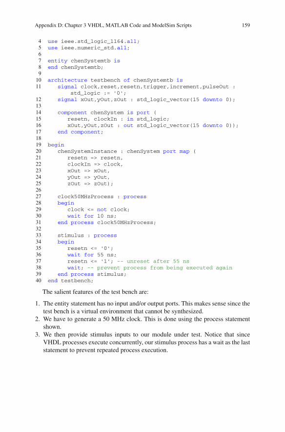
Appendix D: Chapter 3 VHDL, MATLAB Code and ModelSim Scripts 159
4 use ieee.std_logic_1164.all;5 use ieee.numeric_std.all;67 entity chenSystemtb is8 end chenSystemtb;910 architecture testbench of chenSystemtb is11 signal clock,reset,resetn,trigger,increment,pulseOut :
std_logic := '0';12 signal xOut,yOut,zOut : std_logic_vector(15 downto 0);1314 component chenSystem is port (15 resetn, clockIn : in std_logic;16 xOut,yOut,zOut : out std_logic_vector(15 downto 0));17 end component;1819 begin20 chenSystemInstance : chenSystem port map (21 resetn => resetn,22 clockIn => clock,23 xOut => xOut,24 yOut => yOut,25 zOut => zOut);2627 clock50MHzProcess : process28 begin29 clock <= not clock;30 wait for 10 ns;31 end process clock50MHzProcess;3233 stimulus : process34 begin35 resetn <= '0';36 wait for 55 ns;37 resetn <= '1'; -- unreset after 55 ns38 wait; -- prevent process from being executed again39 end process stimulus;40 end testbench;
The salient features of the test bench are:
1. The entity statement has no input and/or output ports. This makes sense since thetest bench is a virtual environment that cannot be synthesized.
2. We have to generate a 50 MHz clock. This is done using the process statementshown.
3. We then provide stimulus inputs to our module under test. Notice that sinceVHDL processes execute concurrently, our stimulus process has a wait as the laststatement to prevent repeated process execution.
160 Appendix D: Chapter 3 VHDL, MATLAB Code and ModelSim Scripts
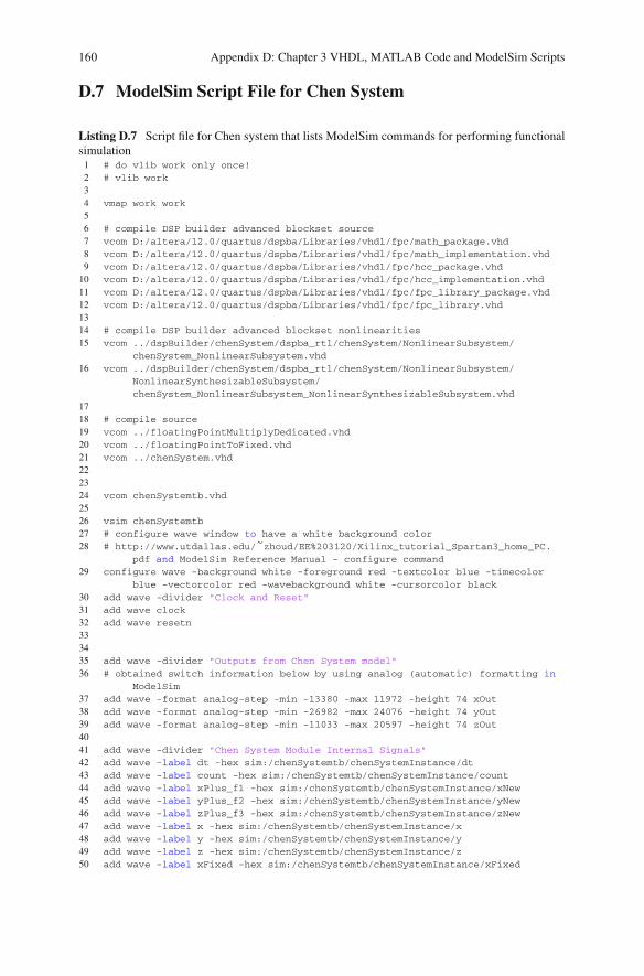
D.7 ModelSim Script File for Chen System
Listing D.7 Script file for Chen system that lists ModelSim commands for performing functionalsimulation1 # do vlib work only once!2 # vlib work34 vmap work work56 # compile DSP builder advanced blockset source7 vcom D:/altera/12.0/quartus/dspba/Libraries/vhdl/fpc/math_package.vhd8 vcom D:/altera/12.0/quartus/dspba/Libraries/vhdl/fpc/math_implementation.vhd9 vcom D:/altera/12.0/quartus/dspba/Libraries/vhdl/fpc/hcc_package.vhd
10 vcom D:/altera/12.0/quartus/dspba/Libraries/vhdl/fpc/hcc_implementation.vhd11 vcom D:/altera/12.0/quartus/dspba/Libraries/vhdl/fpc/fpc_library_package.vhd12 vcom D:/altera/12.0/quartus/dspba/Libraries/vhdl/fpc/fpc_library.vhd1314 # compile DSP builder advanced blockset nonlinearities15 vcom ../dspBuilder/chenSystem/dspba_rtl/chenSystem/NonlinearSubsystem/
chenSystem_NonlinearSubsystem.vhd16 vcom ../dspBuilder/chenSystem/dspba_rtl/chenSystem/NonlinearSubsystem/
NonlinearSynthesizableSubsystem/chenSystem_NonlinearSubsystem_NonlinearSynthesizableSubsystem.vhd
1718 # compile source19 vcom ../floatingPointMultiplyDedicated.vhd20 vcom ../floatingPointToFixed.vhd21 vcom ../chenSystem.vhd222324 vcom chenSystemtb.vhd2526 vsim chenSystemtb27 # configure wave window to have a white background color28 # http://www.utdallas.edu/˜zhoud/EE%203120/Xilinx_tutorial_Spartan3_home_PC.
pdf and ModelSim Reference Manual - configure command29 configure wave -background white -foreground red -textcolor blue -timecolor
blue -vectorcolor red -wavebackground white -cursorcolor black30 add wave -divider "Clock and Reset"31 add wave clock32 add wave resetn333435 add wave -divider "Outputs from Chen System model"36 # obtained switch information below by using analog (automatic) formatting in
ModelSim37 add wave -format analog-step -min -13380 -max 11972 -height 74 xOut38 add wave -format analog-step -min -26982 -max 24076 -height 74 yOut39 add wave -format analog-step -min -11033 -max 20597 -height 74 zOut4041 add wave -divider "Chen System Module Internal Signals"42 add wave -label dt -hex sim:/chenSystemtb/chenSystemInstance/dt43 add wave -label count -hex sim:/chenSystemtb/chenSystemInstance/count44 add wave -label xPlus_f1 -hex sim:/chenSystemtb/chenSystemInstance/xNew45 add wave -label yPlus_f2 -hex sim:/chenSystemtb/chenSystemInstance/yNew46 add wave -label zPlus_f3 -hex sim:/chenSystemtb/chenSystemInstance/zNew47 add wave -label x -hex sim:/chenSystemtb/chenSystemInstance/x48 add wave -label y -hex sim:/chenSystemtb/chenSystemInstance/y49 add wave -label z -hex sim:/chenSystemtb/chenSystemInstance/z50 add wave -label xFixed -hex sim:/chenSystemtb/chenSystemInstance/xFixed

Appendix D: Chapter 3 VHDL, MATLAB Code and ModelSim Scripts 161
51 add wave -label yFixed -hex sim:/chenSystemtb/chenSystemInstance/yFixed52 add wave -label zFixed -hex sim:/chenSystemtb/chenSystemInstance/zFixed5354 # run 1ms
Appendix EChapter 4 MATLAB Code, VHDLand ModelSim Scripts
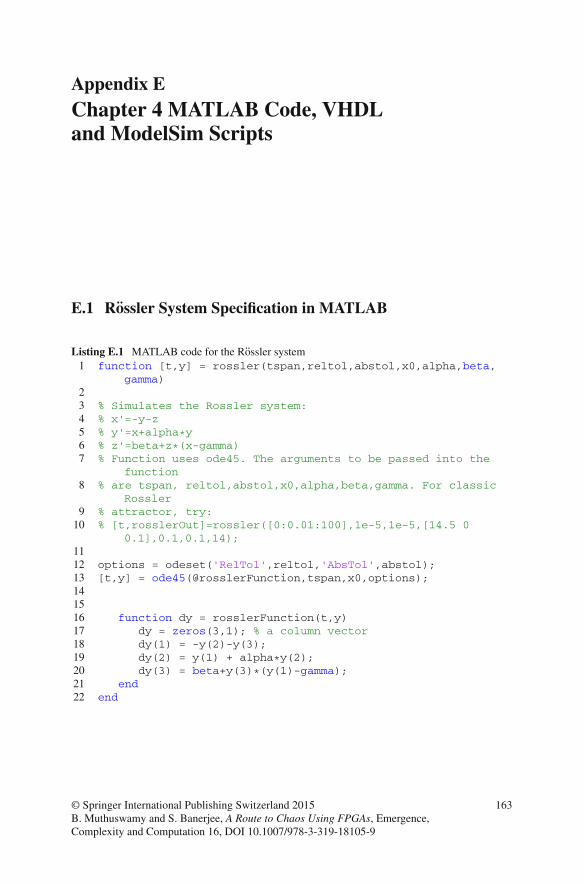
E.1 Rossler System Specification in MATLAB
Listing E.1 MATLAB code for the Rossler system1 function [t,y] = rossler(tspan,reltol,abstol,x0,alpha,beta,
gamma)23 % Simulates the Rossler system:4 % x'=-y-z5 % y'=x+alpha*y6 % z'=beta+z*(x-gamma)7 % Function uses ode45. The arguments to be passed into the
function8 % are tspan, reltol,abstol,x0,alpha,beta,gamma. For classic
Rossler9 % attractor, try:10 % [t,rosslerOut]=rossler([0:0.01:100],1e-5,1e-5,[14.5 0
0.1],0.1,0.1,14);1112 options = odeset('RelTol',reltol,'AbsTol',abstol);13 [t,y] = ode45(@rosslerFunction,tspan,x0,options);141516 function dy = rosslerFunction(t,y)17 dy = zeros(3,1); % a column vector18 dy(1) = -y(2)-y(3);19 dy(2) = y(1) + alpha*y(2);20 dy(3) = beta+y(3)*(y(1)-gamma);21 end22 end
© Springer International Publishing Switzerland 2015B. Muthuswamy and S. Banerjee, A Route to Chaos Using FPGAs, Emergence,Complexity and Computation 16, DOI 10.1007/978-3-319-18105-9
163
164 Appendix E: Chapter 4 MATLAB Code, VHDL and ModelSim Scripts
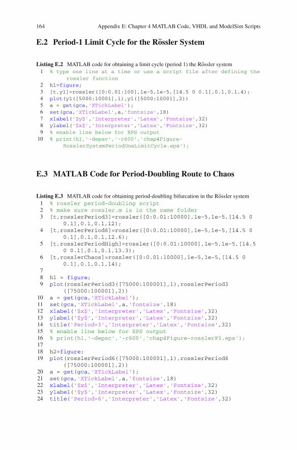
E.2 Period-1 Limit Cycle for the Rossler System
Listing E.2 MATLAB code for obtaining a limit cycle (period 1) the Rossler system1 % type one line at a time or use a script file after defining the
rossler function2 h1=figure;3 [t,y1]=rossler([0:0.01:100],1e-5,1e-5,[14.5 0 0.1],0.1,0.1,4);4 plot(y1([5000:10001],1),y1([5000:10001],2))5 a = get(gca,'XTickLabel');6 set(gca,'XTickLabel',a,'fontsize',18)7 xlabel('$y$','Interpreter','Latex','Fontsize',32)8 ylabel('$x$','Interpreter','Latex','Fontsize',32)9 % enable line below for EPS output
10 % print(h1,'-depsc','-r600','chap4Figure-RosslerSystemPeriodOneLimitCycle.eps');
E.3 MATLAB Code for Period-Doubling Route to Chaos
Listing E.3 MATLAB code for obtaining period-doubling bifurcation in the Rossler system1 % rossler period-doubling script2 % make sure rossler.m is in the same folder3 [t,rosslerPeriod3]=rossler([0:0.01:10000],1e-5,1e-5,[14.5 0
0.1],0.1,0.1,12);4 [t,rosslerPeriod6]=rossler([0:0.01:10000],1e-5,1e-5,[14.5 0
0.1],0.1,0.1,12.6);5 [t,rosslerPeriodHigh]=rossler([0:0.01:10000],1e-5,1e-5,[14.5
0 0.1],0.1,0.1,13.3);6 [t,rosslerChaos]=rossler([0:0.01:10000],1e-5,1e-5,[14.5 0
0.1],0.1,0.1,14);78 h1 = figure;9 plot(rosslerPeriod3([75000:100001],1),rosslerPeriod3
([75000:100001],2))10 a = get(gca,'XTickLabel');11 set(gca,'XTickLabel',a,'fontsize',18)12 xlabel('$x$','Interpreter','Latex','Fontsize',32)13 ylabel('$y$','Interpreter','Latex','Fontsize',32)14 title('Period=3','Interpreter','Latex','Fontsize',32)15 % enable line below for EPS output16 % print(h1,'-depsc','-r600','chap4Figure-rosslerP3.eps');1718 h2=figure;19 plot(rosslerPeriod6([75000:100001],1),rosslerPeriod6
([75000:100001],2))20 a = get(gca,'XTickLabel');21 set(gca,'XTickLabel',a,'fontsize',18)22 xlabel('$x$','Interpreter','Latex','Fontsize',32)23 ylabel('$y$','Interpreter','Latex','Fontsize',32)24 title('Period=6','Interpreter','Latex','Fontsize',32)
Appendix E: Chapter 4 MATLAB Code, VHDL and ModelSim Scripts 165
25 % enable line below for EPS output26 % print(h2,'-depsc','-r600','chap4Figure-rosslerP6.eps');2728 h3=figure;29 plot(rosslerPeriodHigh([75000:100001],1),rosslerPeriodHigh
([75000:100001],2))30 a = get(gca,'XTickLabel');31 set(gca,'XTickLabel',a,'fontsize',18)32 xlabel('$x$','Interpreter','Latex','Fontsize',32)33 ylabel('$y$','Interpreter','Latex','Fontsize',32)34 title('Higher Period','Interpreter','Latex','Fontsize',32)35 % enable line below for EPS output36 % print(h3,'-depsc','-r600','chap4Figure-rosslerHighPeriod.
eps');3738 h4=figure;39 plot(rosslerChaos([75000:100001],1),rosslerChaos
([75000:100001],2))40 a = get(gca,'XTickLabel');41 set(gca,'XTickLabel',a,'fontsize',18)42 xlabel('$x$','Interpreter','Latex','Fontsize',32)43 ylabel('$y$','Interpreter','Latex','Fontsize',32)44 title('Chaos','Interpreter','Latex','Fontsize',32)45 % enable line below for EPS output46 % print(h4,'-depsc','-r600','chap4Figure-rosslerChaos.eps');
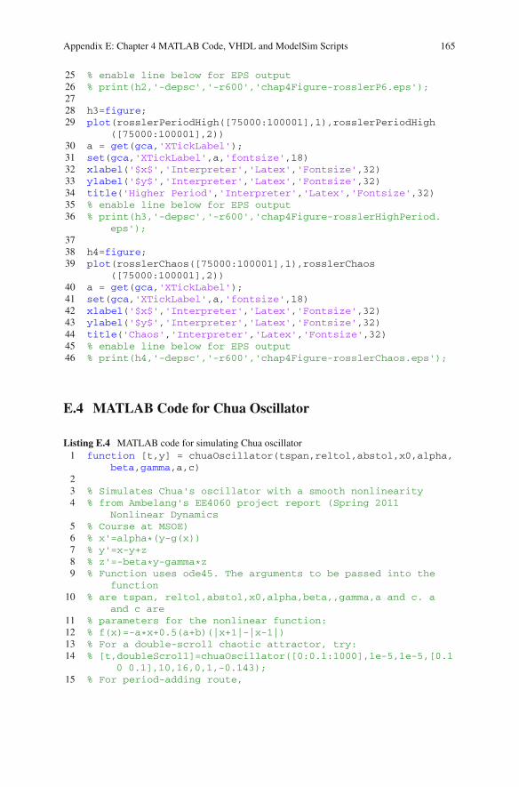
E.4 MATLAB Code for Chua Oscillator
Listing E.4 MATLAB code for simulating Chua oscillator1 function [t,y] = chuaOscillator(tspan,reltol,abstol,x0,alpha,
beta,gamma,a,c)23 % Simulates Chua's oscillator with a smooth nonlinearity4 % from Ambelang's EE4060 project report (Spring 2011
Nonlinear Dynamics5 % Course at MSOE)6 % x'=alpha*(y-g(x))7 % y'=x-y+z8 % z'=-beta*y-gamma*z9 % Function uses ode45. The arguments to be passed into the
function10 % are tspan, reltol,abstol,x0,alpha,beta,,gamma,a and c. a
and c are11 % parameters for the nonlinear function:12 % f(x)=-a*x+0.5(a+b)(|x+1|-|x-1|)13 % For a double-scroll chaotic attractor, try:14 % [t,doubleScroll]=chuaOscillator([0:0.1:1000],1e-5,1e-5,[0.1
0 0.1],10,16,0,1,-0.143);15 % For period-adding route,

166 Appendix E: Chapter 4 MATLAB Code, VHDL and ModelSim Scripts
16 % [t,period3]=chuaOscillator([0:0.1:1000],1e-5,1e-5,[0.1 00.1],3.708,3.499,0.076,1,-0.276);
17 % [t,chaosAfterPeriod3]=chuaOscillator([0:0.1:1000],1e-5,1e-5,[0.1 0 0.1],3.708,3.549,0.076,1,-0.276);
18 % [t,period4]=chuaOscillator([0:0.1:1000],1e-5,1e-5,[0.1 00.1],3.708,3.574,0.076,1,-0.276);
19 % [t,chaosAfterPeriod4]=chuaOscillator([0:0.1:1000],1e-5,1e-5,[0.1 0 0.1],3.708,3.6,0.076,1,-0.276);
2021 options = odeset('RelTol',reltol,'AbsTol',abstol);22 [t,y] = ode45(@chuaOscillatorFunction,tspan,x0,options);232425 function dy = chuaOscillatorFunction(t,y)26 dy = zeros(3,1); % a column vector27 dy(1) = alpha*(y(2)-g(y(1),a,c));28 dy(2) = y(1)-y(2)+y(3);29 dy(3) = -beta*y(2)-gamma*y(3);30 end3132 function y=g(x,a,c)33 y=a*xˆ3+c*x;34 end35 end
E.5 MATLAB Code for Period-Adding Route to Chaos
Listing E.5 MATLAB code for obtaining the period-adding route to chaos in Fig. 4.31 % period-adding, using Chua's oscillator2 % Make sure chuaOscillator.m is in the same folder3 [t,period3]=chuaOscillator([0:0.1:1000],1e-5,1e-5,[0.1 0
0.1],3.708,3.499,0.076,1,-0.276);4 [t,chaosAfterPeriod3]=chuaOscillator([0:0.1:1000],1e-5,1e-5,[0.1
0 0.1],3.708,3.549,0.076,1,-0.276);5 [t,period4]=chuaOscillator([0:0.1:1000],1e-5,1e-5,[0.1 0
0.1],3.708,3.574,0.076,1,-0.276);6 [t,chaosAfterPeriod4]=chuaOscillator([0:0.1:1000],1e-5,1e-5,[0.1
0 0.1],3.708,3.6,0.076,1,-0.276);78 h1 = figure;9 plot(period3([5000:10001],1),period3([5000:10001],2))
10 a = get(gca,'XTickLabel');11 set(gca,'XTickLabel',a,'fontsize',18)12 xlabel('$y$','Interpreter','Latex','Fontsize',32)13 ylabel('$x$','Interpreter','Latex','Fontsize',32)14 title('3:3 Limit Cycle','Fontsize',32)15 % enable line below for EPS output16 % print(h1,'-depsc','-r600','chap4Figure-chuaOscillatorP3.eps');1718 h2 = figure;

Appendix E: Chapter 4 MATLAB Code, VHDL and ModelSim Scripts 167
19 plot(chaosAfterPeriod3([5000:10001],1),chaosAfterPeriod3([5000:10001],2))
20 a = get(gca,'XTickLabel');21 set(gca,'XTickLabel',a,'fontsize',18)22 xlabel('$y$','Interpreter','Latex','Fontsize',32)23 ylabel('$x$','Interpreter','Latex','Fontsize',32)24 title('Chaos after 3:3 Limit Cycle ','Fontsize',32)25 % enable line below for EPS output26 % print(h2,'-depsc','-r600','chap4Figure-
chuaOscillatorChaosAfterP3.eps');2728 h3 = figure;29 plot(period4([5000:10001],1),period4([5000:10001],2))30 a = get(gca,'XTickLabel');31 set(gca,'XTickLabel',a,'fontsize',18)32 xlabel('$y$','Interpreter','Latex','Fontsize',32)33 ylabel('$x$','Interpreter','Latex','Fontsize',32)34 title('4:4 Limit Cycle ','Fontsize',32)35 % enable line below for EPS output36 % print(h3,'-depsc','-r600','chap4Figure-chuaOscillatorP4.eps');3738 h4 = figure;39 plot(chaosAfterPeriod4([5000:10001],1),chaosAfterPeriod4
([5000:10001],2))40 a = get(gca,'XTickLabel');41 set(gca,'XTickLabel',a,'fontsize',18)42 xlabel('$y$','Interpreter','Latex','Fontsize',32)43 ylabel('$x$','Interpreter','Latex','Fontsize',32)44 title('Chaos after 4:4 Limit Cycle ','Fontsize',32)45 % enable line below for EPS output46 % print(h4,'-depsc','-r600','chap4Figure-
chuaOscillatorChaosAfterP4.eps');
E.6 MATLAB Code for Torus-Breakdown System
Listing E.6 MATLAB code implementing Eqs. (4.8)–(4.10)1 function [t,y] = torusBreakdown(tspan,reltol,abstol,x0,alpha,beta
,a,b)23 % Simulates the torus breakdown system from Matsumoto et. al.:4 % x'=-alpha*f(y-x)5 % y'=-f(y-x)-z6 % z'=beta*y7 % Function uses ode45. The arguments to be passed into the
function8 % are tspan, reltol,abstol,x0,alpha,beta,a and b. a and b are
parameters9 % for the piecewise-linear function:
10 % f(x)=-a*x+0.5(a+b)(|x+1|-|x-1|)11 % For a folded torus chaotic attractor, try:

168 Appendix E: Chapter 4 MATLAB Code, VHDL and ModelSim Scripts
12 % [t,torusBreakdownOut]=torusBreakdown([0:0.1:1000],1e-5,1e-5,13 % [0.1 0 0.1],15,1,0.07,0.1);1415 options = odeset('RelTol',reltol,'AbsTol',abstol);16 [t,y] = ode45(@torusBreakdownFunction,tspan,x0,options);171819 function dy = torusBreakdownFunction(t,y)20 dy = zeros(3,1); % a column vector21 dy(1) = -alpha*f(y(2)-y(1),a,b);22 dy(2) = -f(y(2)-y(1),a,b)-y(3);23 dy(3) = beta*y(2);24 end2526 function y=f(x,a,b)27 y=-a*x+0.5*(a+b)*(abs(x+ones(length(x),1))-abs(x-ones(
length(x),1)));28 end29 end
E.7 MATLAB Code for Quasi-Periodic Route to Chaos
Listing E.7 MATLAB code for obtaining torus-breakdown route to chaos in Fig. 4.41 % torus breakdown script2 % make sure torusBreakdown.m is in the same folder3 [t,torusAttractorTwoTorus]=torusBreakdown([0:0.1:1000],1e-5,1e
-5,[0.1 0 0.1],2.0,1,0.07,0.1);4 [t,torusAttractorPeriod8]=torusBreakdown([0:0.1:1000],1e-5,1e
-5,[0.1 0 0.1],8.0,1,0.07,0.1);5 [t,torusAttractorPeriod15]=torusBreakdown([0:0.1:1000],1e-5,1e
-5,[0.1 0 0.1],8.8,1,0.07,0.1);6 [t,torusAttractorTorusBreakdown]=torusBreakdown([0:0.1:1000],1e
-5,1e-5,[0.1 0 0.1],15.0,1,0.07,0.1);78 h1 = figure;9 plot(torusAttractorTwoTorus([7500:10001],2),torusAttractorTwoTorus
([7500:10001],1))10 % http://www.mathworks.com/matlabcentral/newsreader/view_thread
/28815911 a = get(gca,'XTickLabel');12 set(gca,'XTickLabel',a,'fontsize',18)13 xlabel('$y$','Interpreter','Latex','Fontsize',32)14 ylabel('$x$','Interpreter','Latex','Fontsize',32)15 title('Two-torus','Interpreter','Latex','Fontsize',32)16 % enable line below for EPS output17 %print(h1,'-depsc','-r600','chap4Figure-torusBreakDownTwoTorus.eps
');1819 h2=figure;

Appendix E: Chapter 4 MATLAB Code, VHDL and ModelSim Scripts 169
20 plot(torusAttractorPeriod8([7500:10001],2),torusAttractorPeriod8([7500:10001],1))
21 a = get(gca,'XTickLabel');22 set(gca,'XTickLabel',a,'fontsize',18)23 xlabel('$y$','Interpreter','Latex','Fontsize',32)24 ylabel('$x$','Interpreter','Latex','Fontsize',32)25 title('Period-8','Interpreter','Latex','Fontsize',32)26 % enable line below for EPS output27 %print(h2,'-depsc','-r600','chap4Figure-torusBreakDownPeriod8.eps
');2829 h3=figure;30 plot(torusAttractorPeriod15([7500:10001],2),torusAttractorPeriod15
([7500:10001],1))31 a = get(gca,'XTickLabel');32 set(gca,'XTickLabel',a,'fontsize',18)33 xlabel('$y$','Interpreter','Latex','Fontsize',32)34 ylabel('$x$','Interpreter','Latex','Fontsize',32)35 title('Period-15','Interpreter','Latex','Fontsize',32)36 % enable line below for EPS output37 %print(h3,'-depsc','-r600','chap4Figure-torusBreakDownPeriod15.eps
');3839 h4=figure;40 plot(torusAttractorTorusBreakdown([7500:10001],2),
torusAttractorTorusBreakdown([7500:10001],1))41 a = get(gca,'XTickLabel');42 set(gca,'XTickLabel',a,'fontsize',18)43 xlabel('$y$','Interpreter','Latex','Fontsize',32)44 ylabel('$x$','Interpreter','Latex','Fontsize',32)45 title('Chaos','Interpreter','Latex','Fontsize',32)46 % enable line below for EPS output47 %print(h4,'-depsc','-r600','chap4Figure-
torusAttractorTorusBreakdown.eps');
E.8 MATLAB Code with Chua Oscillator Parameter Valuesfor Intermittency Route to Chaos
Listing E.8 MATLAB code implementing Eqs. (4.19)–(4.22)1 function [t,y] = chuaOscillatorIntermittency(tspan,reltol,
abstol,x0,alpha,beta,gamma,a,b)23 % Simulates Chua's oscillator with a piecewise-linear
nonlinearity4 % x'=alpha*(y-x-f(x))5 % y'=x-y+z6 % z'=-beta*y-gamma*z7 % f(x) = bx + 0.5*(a-b)*(|x+1|-|x-1|)8 % Function uses ode45. The arguments to be passed into the
function
170 Appendix E: Chapter 4 MATLAB Code, VHDL and ModelSim Scripts
9 % are tspan, reltol,abstol,x0,alpha,beta,,gamma,a and b.1011 options = odeset('RelTol',reltol,'AbsTol',abstol);12 [t,y] = ode45(@chuaOscillatorFunction,tspan,x0,options);131415 function dy = chuaOscillatorFunction(t,y)16 dy = zeros(3,1); % a column vector17 dy(1) = alpha*(y(2)-y(1)-f(y(1),a,b));18 dy(2) = y(1)-y(2)+y(3);19 dy(3) = -beta*y(2)-gamma*y(3);20 end2122 function y=f(x,a,b)23 y=b*x+0.5*(a-b)*(abs(x+ones(length(x),1))-abs(x-ones(
length(x),1)));24 end25 end
E.9 MATLAB Code for Plotting Intermittency Routeto Chaos
Listing E.9 MATLAB code for obtaining intermittency route to chaos in Fig. 4.51 % Intermittency script2 % make sure chuaOscillatorIntermittency.m is in the same folder3 alpha=-75.018755;4 a=-0.98;5 b=-2.4;67 % Periodic8 beta=44.803;9 gamma=-4.480;10 [t,intermittencyPeriodic]=chuaOscillatorIntermittency([0:0.01:1000],1e
-4,1e-4,[0.1 0 0.1],alpha,beta,gamma,a,b);11 h1a = figure;12 plot(intermittencyPeriodic(:,2),intermittencyPeriodic(:,3))13 % http://www.mathworks.com/matlabcentral/newsreader/view_thread/28815914 figureProperties = get(gca,'XTickLabel');15 set(gca,'XTickLabel',figureProperties,'fontsize',18)16 xlabel('$y$','Interpreter','Latex','Fontsize',32)17 ylabel('$z$','Interpreter','Latex','Fontsize',32)18 title('Limit Cycle(s)','Interpreter','Latex','Fontsize',32)19 % enable line below for EPS output20 % print(h1a,'-depsc','-r600','chap4Figure-intermittencyPeriodic.eps');2122 h1b = figure;23 plot(t([75000:83000],1),intermittencyPeriodic([75000:83000],1));24 % http://www.mathworks.com/matlabcentral/newsreader/view_thread/28815925 figureProperties = get(gca,'XTickLabel');26 set(gca,'XTickLabel',figureProperties,'fontsize',18)27 xlabel('$t$','Interpreter','Latex','Fontsize',32)28 ylabel('$x$','Interpreter','Latex','Fontsize',32)

Appendix E: Chapter 4 MATLAB Code, VHDL and ModelSim Scripts 171
29 title('Limit Cycle(s) (time-domain)','Interpreter','Latex','Fontsize',32)
30 %enable line below for EPS output31 % print(h1b,'-depsc','-r600','chap4Figure-intermittencyPeriodic-
TimeDomain.eps');3233 % Chaos, one instance34 beta=43.994721;35 gamma=-4.3994721;36 [t,intermittencyChaosOne]=chuaOscillatorIntermittency([0:0.01:1000],1e
-6,1e-6,[0.1,0,0.1],alpha,beta,gamma,a,b);37 h2a = figure;38 plot(intermittencyChaosOne([75000:100001],3),intermittencyChaosOne
([75000:100001],1))39 % http://www.mathworks.com/matlabcentral/newsreader/view_thread/28815940 figureProperties = get(gca,'XTickLabel');41 set(gca,'XTickLabel',figureProperties,'fontsize',18)42 xlabel('$z$','Interpreter','Latex','Fontsize',32)43 ylabel('$x$','Interpreter','Latex','Fontsize',32)44 title('Intermittency','Interpreter','Latex','Fontsize',32)45 % enable line below for EPS output46 % print(h2a,'-depsc','-r600','chap4Figure-intermittencyChaosOne.eps');4748 h2b = figure;49 plot(t([75000:83000],1),intermittencyChaosOne([75000:83000],2))50 % http://www.mathworks.com/matlabcentral/newsreader/view_thread/28815951 figureProperties = get(gca,'XTickLabel');52 set(gca,'XTickLabel',figureProperties,'fontsize',18)53 xlabel('$t$','Interpreter','Latex','Fontsize',32)54 ylabel('$y$','Interpreter','Latex','Fontsize',32)55 title('Intermittency Chaos (time-domain)','Interpreter','Latex','
Fontsize',32)56 % enable line below for EPS output57 % print(h2b,'-depsc','-r600','chap4Figure-intermittencyChaosOne-
TimeDomain.eps');5859 % Chaos, second instance60 beta=31.746032;61 gamma=-3.1746032;62 [t,intermittencyChaosTwo]=chuaOscillatorIntermittency([0:0.01:1000],1e
-6,1e-6,[0.1,0,0.1],alpha,beta,gamma,a,b);63 h3a = figure;64 plot(intermittencyChaosTwo([75000:100001],3),intermittencyChaosTwo
([75000:100001],1))65 % http://www.mathworks.com/matlabcentral/newsreader/view_thread/28815966 figureProperties = get(gca,'XTickLabel');67 set(gca,'XTickLabel',figureProperties,'fontsize',18)68 xlabel('$z$','Interpreter','Latex','Fontsize',32)69 ylabel('$x$','Interpreter','Latex','Fontsize',32)70 title('Intermittency','Interpreter','Latex','Fontsize',32)71 % enable line below for EPS output72 % print(h3a,'-depsc','-r600','chap4Figure-intermittencyChaosTwo.eps');7374 h3b = figure;75 plot(t([75000:83000],1),intermittencyChaosTwo([75000:83000],2))76 % http://www.mathworks.com/matlabcentral/newsreader/view_thread/28815977 figureProperties = get(gca,'XTickLabel');78 set(gca,'XTickLabel',figureProperties,'fontsize',18)79 xlabel('$t$','Interpreter','Latex','Fontsize',32)
172 Appendix E: Chapter 4 MATLAB Code, VHDL and ModelSim Scripts
80 ylabel('$y$','Interpreter','Latex','Fontsize',32)81 title('Intermittency Chaos (time-domain)','Interpreter','Latex','
Fontsize',32)82 % enable line below for EPS output83 % print(h3b,'-depsc','-r600','chap4Figure-intermittencyChaosTwo-
TimeDomain.eps');8485 % Chaos, third instance86 beta=31.25;87 gamma=-3.125;88 [t,intermittencyChaosThree]=chuaOscillatorIntermittency([0:0.01:1000],1e
-6,1e-6,[0.1,0,0.1],alpha,beta,gamma,a,b);89 h4a = figure;90 plot(intermittencyChaosThree([75000:100001],3),intermittencyChaosThree
([75000:100001],1))91 % http://www.mathworks.com/matlabcentral/newsreader/view_thread/28815992 figureProperties = get(gca,'XTickLabel');93 set(gca,'XTickLabel',figureProperties,'fontsize',18)94 xlabel('$z$','Interpreter','Latex','Fontsize',32)95 ylabel('$x$','Interpreter','Latex','Fontsize',32)96 title('Intermittency','Interpreter','Latex','Fontsize',32)97 % enable line below for EPS output98 % print(h4a,'-depsc','-r600','chap4Figure-intermittencyChaosThree.eps');99
100 h4b = figure;101 plot(t([75000:83000],1),intermittencyChaosThree([75000:83000],2))102 % http://www.mathworks.com/matlabcentral/newsreader/view_thread/288159103 figureProperties = get(gca,'XTickLabel');104 set(gca,'XTickLabel',figureProperties,'fontsize',18)105 xlabel('$t$','Interpreter','Latex','Fontsize',32)106 ylabel('$y$','Interpreter','Latex','Fontsize',32)107 title('Intermittency Chaos (time-domain)','Interpreter','Latex','
Fontsize',32)108 % enable line below for EPS output109 % print(h4b,'-depsc','-r600','chap4Figure-intermittencyChaosThree-
TimeDomain.eps');
E.10 MATLAB Code for Resource-Consumer-PredatorModel
Listing E.10 MATLAB code implementing Eqs. ( 4.23)–(4.25)1 function [t,y] = resourcePredatorPrey(tspan,reltol,abstol,x0,xC,
yC,xP,yP,R0,C0,K)23 % Simulates the resource predator prey model from4 % "Controlling transient chaos in deterministic flows with
applications5 % to electrical power systems and ecology". Physical Review E,
59(2),6 % 1646 - 1655, 1999.7 % Function uses ode45. The arguments to be passed into the
function8 % are tspan, reltol,abstol,x0,alpha,beta,,gamma,a and b.

Appendix E: Chapter 4 MATLAB Code, VHDL and ModelSim Scripts 173
910 options = odeset('RelTol',reltol,'AbsTol',abstol);11 [t,y] = ode45(@resourcePredatorPreyFunction,tspan,x0,options);12 function dy = resourcePredatorPreyFunction(t,y)13 dy = zeros(3,1); % a column vector14 dy(1) = y(1)*(1-y(1)/K)-(xC*yC*y(2)*y(1))/(y(1)+R0);15 dy(2) = xC*y(2)*((yC*y(1))/(y(1)+R0)-1)-(xP*yP*y(3)*y(2))/(
y(2)+C0);16 dy(3) = xP*y(3)*(-1+(yP*y(2))/(y(2)+C0));17 end181920 end
E.11 MATLAB Code for Chaotic Transients
Listing E.11 MATLAB code for simulating chaotic transients and crisis phenomenon in Fig. 4.61 % chaotic transients script2 % make sure resourcePredatorPrey.m is in the same folder3 xC=0.4;4 yC=2.009;5 xP=0.08;6 yP=2.876;7 R0=0.16129;8 C0=0.5;9
10 % Periodic attractor and chaotic attractor co-exist11 K=0.99;12 [t,chaoticTransientPeriodic]=resourcePredatorPrey
([0:0.1:1000],1e-4,1e-4,[0.1 0.2 0.1],xC,yC,xP,yP,R0,C0,K);
13 h1 = figure;14 plot(chaoticTransientPeriodic(:,1),chaoticTransientPeriodic
(:,2))15 % http://www.mathworks.com/matlabcentral/newsreader/
view_thread/28815916 figureProperties = get(gca,'XTickLabel');17 set(gca,'XTickLabel',figureProperties,'fontsize',18)18 xlabel('$R$','Interpreter','Latex','Fontsize',32)19 ylabel('$C$','Interpreter','Latex','Fontsize',32)20 title('Limit Cycle','Interpreter','Latex','Fontsize',32)21 % enable line below for EPS output22 % print(h1,'-depsc','-r600','chap4Figure-
chaoticTransientsPeriodic.eps');2324 h2 = figure;25 plot(t(:,1),chaoticTransientPeriodic(:,3))

174 Appendix E: Chapter 4 MATLAB Code, VHDL and ModelSim Scripts
26 % http://www.mathworks.com/matlabcentral/newsreader/view_thread/288159
27 figureProperties = get(gca,'XTickLabel');28 set(gca,'XTickLabel',figureProperties,'fontsize',18)29 xlabel('$t$','Interpreter','Latex','Fontsize',32)30 ylabel('$P$','Interpreter','Latex','Fontsize',32)31 title('$P$ population decays','Interpreter','Latex','
Fontsize',32)32 %enable line below for EPS output33 % print(h2,'-depsc','-r600','chap4Figure-
chaoticTransientsPeriodic-TimeDomain.eps');3435 h3 = figure;36 [t,chaoticTransientChaos]=resourcePredatorPrey
([0:0.1:1000],1e-4,1e-4,[0.55 0.35 0.8],xC,yC,xP,yP,R0,C0,K);
37 plot(chaoticTransientChaos(:,2),chaoticTransientChaos(:,3))38 % http://www.mathworks.com/matlabcentral/newsreader/
view_thread/28815939 figureProperties = get(gca,'XTickLabel');40 set(gca,'XTickLabel',figureProperties,'fontsize',18)41 xlabel('$R$','Interpreter','Latex','Fontsize',32)42 ylabel('$P$','Interpreter','Latex','Fontsize',32)43 title('Chaos','Interpreter','Latex','Fontsize',32)44 %enable line below for EPS output45 % print(h3,'-depsc','-r600','chap4Figure-
chaoticTransientsChaos.eps');4647 % Crisis past critical carrying capacity.48 K=1.02;49 [t,chaoticTransientCrisis]=resourcePredatorPrey
([0:0.1:1000],1e-4,1e-4,[0.55 0.35 0.8],xC,yC,xP,yP,R0,C0,K);
50 h4 = figure;51 plot(t(:,1),chaoticTransientCrisis(:,3))52 % http://www.mathworks.com/matlabcentral/newsreader/
view_thread/28815953 figureProperties = get(gca,'XTickLabel');54 set(gca,'XTickLabel',figureProperties,'fontsize',18)55 xlabel('$t$','Interpreter','Latex','Fontsize',32)56 ylabel('$P$','Interpreter','Latex','Fontsize',32)57 title('$P$ time series','Interpreter','Latex','Fontsize',32)58 % enable line below for EPS output59 % print(h4,'-depsc','-r600','chap4Figure-
chaoticTransientsCrisis.eps');
Appendix E: Chapter 4 MATLAB Code, VHDL and ModelSim Scripts 175
E.12 VHDL Specification for Single Pulse Generator
Listing E.12 VHDL pulse FSM1 library ieee;2 use ieee.std_logic_1164.all;3 use ieee.numeric_std.all;45 entity pulseFSM is port (6 reset,clock,trigger : in std_logic;7 pulseOut,pulseOutSingleClockCycle : out std_logic);8 end pulseFSM;910 architecture mooreFSM of pulseFSM is1112 type state is (resetState,generatePulseCycle1,
generatePulseCycle2,generatePulseCycle3,generatePulseCycle4,generatePulseCycle5,generatePulseCycle6,generatePulseCycle7,generatePulseCycle8,stopPulse,waitForTriggerRelease);
13 signal currentState,nextState : state;1415 begin1617 -- state memory18 stateMemory : process(reset,clock)19 begin20 if reset='1' then21 currentState <= resetState;22 else23 if rising_edge(clock) then24 currentState <= nextState;25 end if;26 end if;27 end process;2829 -- next state logic30 stateTransitionLogic : process (currentState,trigger)31 begin32 case currentState is33 when resetState =>34 if trigger='0' then35 nextState <= resetState;36 else37 nextState <= generatePulseCycle1;38 end if;39 when generatePulseCycle1 =>40 nextState <= generatePulseCycle2;41 when generatePulseCycle2 =>42 nextState <= generatePulseCycle3;43 when generatePulseCycle3 =>

176 Appendix E: Chapter 4 MATLAB Code, VHDL and ModelSim Scripts
44 nextState <= generatePulseCycle4;45 when generatePulseCycle4 =>46 nextState <= generatePulseCycle5;47 when generatePulseCycle5 =>48 nextState <= generatePulseCycle6;49 when generatePulseCycle6 =>50 nextState <= generatePulseCycle7;51 when generatePulseCycle7 =>52 nextState <= generatePulseCycle8;53 when generatePulseCycle8 =>54 nextState <= stopPulse;55 when stopPulse =>56 nextState <= waitForTriggerRelease;57 when waitForTriggerRelease =>58 if trigger='1' then59 nextState <= waitForTriggerRelease;60 else61 nextState <= resetState;62 end if;63 end case;64 end process;6566 -- output logic67 with currentState select68 pulseOut <= '0' when resetState,69 '0' when waitForTriggerRelease,70 '0' when stopPulse,71 '1' when others;7273 -- we enable single clock cycle pulse only after latency
of floating point design has been74 -- accounted for.75 with currentState select76 pulseOutSingleClockCycle <= '1' when stopPulse,77 '0' when others;78 end mooreFSM;
E.13 ModelSim Testbench for Single Pulse Generator
Listing E.13 VHDL pulse FSM test bench1 -- testbench for pulse FSM (bifurcations)23 library ieee;4 use ieee.std_logic_1164.all;5 use ieee.numeric_std.all;67 entity pulseFSMtb is8 end pulseFSMtb;
Appendix E: Chapter 4 MATLAB Code, VHDL and ModelSim Scripts 177
910 architecture testbench of pulseFSMtb is11 signal clock,reset,trigger,pulseOut : std_logic := '0';1213 component pulseFSM is port (14 reset,clock,trigger : in std_logic;15 pulseOut : out std_logic);16 end component;1718 begin19 pulseFSMInstance : pulseFSM port map (20 reset => reset,21 clock => clock,22 trigger => trigger,23 pulseOut => pulseOut);2425 clock50MHzProcess : process26 begin27 clock <= not clock;28 wait for 10 ns;29 end process clock50MHzProcess;3031 stimulus : process32 begin33 reset <= '1';34 trigger <= '0';35 wait for 55 ns;36 reset <= '0'; -- unreset after 55 ns37 wait for 100 ns;38 trigger <= '1';39 wait for 150 ns;40 trigger <= '0';41 wait; -- prevent process from being executed again42 end process stimulus;43 end testbench;
E.14 ModelSim Script File for Single Pulse Generator
Listing E.14 ModelSim script file for pulse FSM1 # do vlib work only once!2 # vlib work34 vmap work work56 # compile source7 vcom ../../pulseFSM.vhd89 # compile testbench10 vcom pulseFSMtb.vhd11

178 Appendix E: Chapter 4 MATLAB Code, VHDL and ModelSim Scripts
12 vsim pulseFSMtb13 # configure wave window to have a white background color14 # http://www.utdallas.edu/˜zhoud/EE%203120/
Xilinx_tutorial_Spartan3_home_PC.pdf and ModelSimReference Manual - configure command
15 configure wave -background white -foreground red -textcolorblue -timecolor blue -vectorcolor red -wavebackgroundwhite -cursorcolor black
16 add wave -divider "Clock and Reset"17 add wave clock18 add wave reset1920 add wave -divider "Input"21 add wave trigger22 add wave -divider "Output"23 add wave pulseOut24 add wave -divider "FSM states"25 add wave -label "Synchronous current state" sim:/pulsefsmtb/
pulseFSMInstance/currentState2627 # run 500ns
E.15 VHDL Specification of Period-Doubling Routeto Chaos
Listing E.15 VHDL specification of period-doubling bifurcation in the Rossler system1 --Single precision (32-bit) floating point realization23 library ieee;4 use ieee.std_logic_1164.all;5 use ieee.std_logic_signed.all;67 entity rosslerSystem is port (8 resetn, clockIn, incrementCountClockN,
incrementGammaClockN,incrementCount,incrementGamma :in std_logic;
9 xOut,yOut,zOut : out std_logic_vector(15 downto 0));10 end rosslerSystem;1112 architecture behavioral of rosslerSystem is1314 signal reset,incrementGammaClock,incrementDecrementGammaPulse,
dFlipFlopClock : std_logic;15 -- constants16 signal dt,output1Over2Scale,output1Over5Scale,alpha,beta,gamma,
gammaSignal : std_logic_vector(31 downto 0);17 -- state variables18 signal x,y,z,xNew,yNew,zNew,xScaled,yScaled,zScaled,xFixed,
yFixed,zFixed : std_logic_vector(31 downto 0);19 -- prescalar20 signal count,countIncrement : integer range 0 to 128;
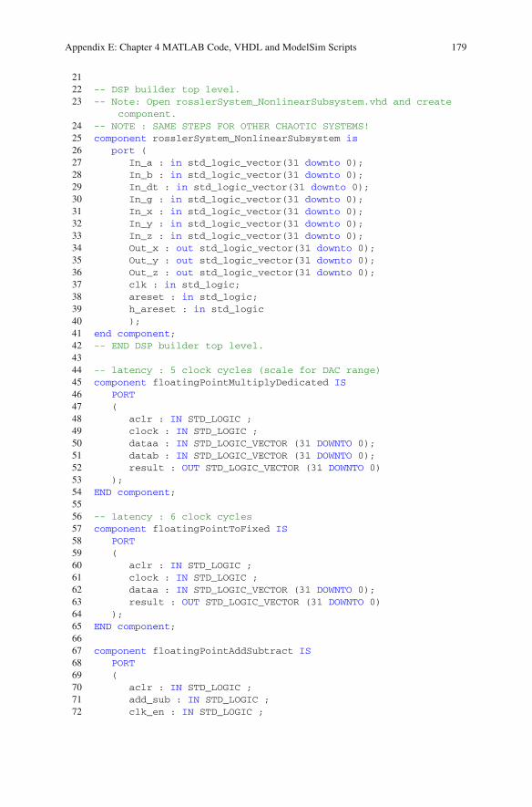
Appendix E: Chapter 4 MATLAB Code, VHDL and ModelSim Scripts 179
2122 -- DSP builder top level.23 -- Note: Open rosslerSystem_NonlinearSubsystem.vhd and create
component.24 -- NOTE : SAME STEPS FOR OTHER CHAOTIC SYSTEMS!25 component rosslerSystem_NonlinearSubsystem is26 port (27 In_a : in std_logic_vector(31 downto 0);28 In_b : in std_logic_vector(31 downto 0);29 In_dt : in std_logic_vector(31 downto 0);30 In_g : in std_logic_vector(31 downto 0);31 In_x : in std_logic_vector(31 downto 0);32 In_y : in std_logic_vector(31 downto 0);33 In_z : in std_logic_vector(31 downto 0);34 Out_x : out std_logic_vector(31 downto 0);35 Out_y : out std_logic_vector(31 downto 0);36 Out_z : out std_logic_vector(31 downto 0);37 clk : in std_logic;38 areset : in std_logic;39 h_areset : in std_logic40 );41 end component;42 -- END DSP builder top level.4344 -- latency : 5 clock cycles (scale for DAC range)45 component floatingPointMultiplyDedicated IS46 PORT47 (48 aclr : IN STD_LOGIC ;49 clock : IN STD_LOGIC ;50 dataa : IN STD_LOGIC_VECTOR (31 DOWNTO 0);51 datab : IN STD_LOGIC_VECTOR (31 DOWNTO 0);52 result : OUT STD_LOGIC_VECTOR (31 DOWNTO 0)53 );54 END component;5556 -- latency : 6 clock cycles57 component floatingPointToFixed IS58 PORT59 (60 aclr : IN STD_LOGIC ;61 clock : IN STD_LOGIC ;62 dataa : IN STD_LOGIC_VECTOR (31 DOWNTO 0);63 result : OUT STD_LOGIC_VECTOR (31 DOWNTO 0)64 );65 END component;6667 component floatingPointAddSubtract IS68 PORT69 (70 aclr : IN STD_LOGIC ;71 add_sub : IN STD_LOGIC ;72 clk_en : IN STD_LOGIC ;
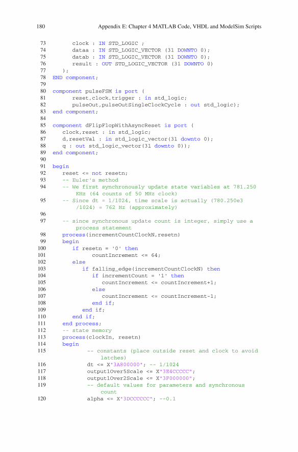
180 Appendix E: Chapter 4 MATLAB Code, VHDL and ModelSim Scripts
73 clock : IN STD_LOGIC ;74 dataa : IN STD_LOGIC_VECTOR (31 DOWNTO 0);75 datab : IN STD_LOGIC_VECTOR (31 DOWNTO 0);76 result : OUT STD_LOGIC_VECTOR (31 DOWNTO 0)77 );78 END component;7980 component pulseFSM is port (81 reset,clock,trigger : in std_logic;82 pulseOut,pulseOutSingleClockCycle : out std_logic);83 end component;8485 component dFlipFlopWithAsyncReset is port (86 clock,reset : in std_logic;87 d,resetVal : in std_logic_vector(31 downto 0);88 q : out std_logic_vector(31 downto 0));89 end component;9091 begin92 reset <= not resetn;93 -- Euler's method94 -- We first synchronously update state variables at 781.250
KHz (64 counts of 50 MHz clock)95 -- Since dt = 1/1024, time scale is actually (780.250e3
/1024) = 762 Hz (approximately)9697 -- since synchronous update count is integer, simply use a
process statement98 process(incrementCountClockN,resetn)99 begin100 if resetn = '0' then101 countIncrement <= 64;102 else103 if falling_edge(incrementCountClockN) then104 if incrementCount = '1' then105 countIncrement <= countIncrement+1;106 else107 countIncrement <= countIncrement-1;108 end if;109 end if;110 end if;111 end process;112 -- state memory113 process(clockIn, resetn)114 begin115 -- constants (place outside reset and clock to avoid
latches)116 dt <= X"3A800000"; -- 1/1024117 output1Over5Scale <= X"3E4CCCCC";118 output1Over2Scale <= X"3F000000";119 -- default values for parameters and synchronous
count120 alpha <= X"3DCCCCCC"; --0.1
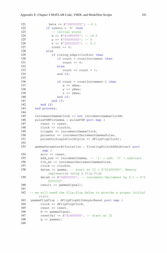
Appendix E: Chapter 4 MATLAB Code, VHDL and ModelSim Scripts 181
121 beta <= X"3DCCCCCC"; --0.1122 if resetn = '0' then123 -- initial state124 x <= X"41680000"; -- 14.5125 y <= X"00000000"; -- 0126 z <= X"3DCCCCCC"; -- 0.1127 count <= 0;128 else129 if rising_edge(clockIn) then130 if count = countIncrement then131 count <= 0;132 else133 count <= count + 1;134 end if;135136 if count = countIncrement-1 then137 x <= xNew;138 y <= yNew;139 z <= zNew;140 end if;141 end if;142 end if;143 end process;144145 incrementGammaClock <= not incrementGammaClockN;146 pulseFSMForGamma : pulseFSM port map (147 reset => reset,148 clock => clockIn,149 trigger => incrementGammaClock,150 pulseOut => incrementDecrementGammaPulse,151 pulseOutSingleClockCycle => dFlipFlopClock);152153 gammaParameterBifurcation : floatingPointAddSubtract port
map (154 aclr => reset,155 add_sub => incrementGamma, -- '1' = add, '0' = subtract156 clk_en => incrementDecrementGammaPulse,157 clock => clockIn,158 dataa => gamma, -- start at 12 = X"41400000". Memory
implemented using D flip-flop159 datab => X"3DCCCCCC", -- increment/decrement by 0.1 = X"3
DCCCCCC"160 result => gammaSignal);161162 -- we will need the flip-flop below to provide a proper initial
state.163 gammaFlipFlop : dFlipFlopWithAsyncReset port map (164 clock => dFlipFlopClock,165 reset => reset,166 d => gammaSignal,167 resetVal => X"41400000", -- start at 12168 q => gamma);169
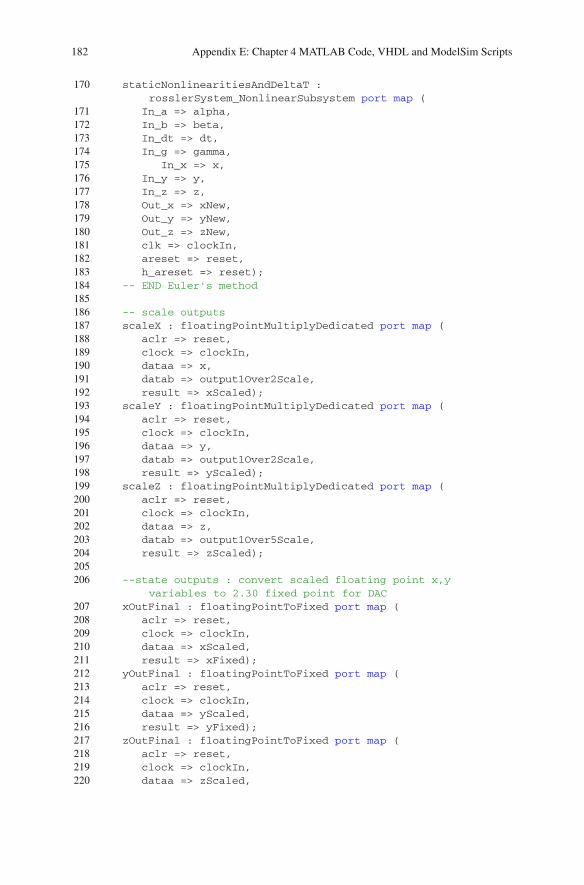
182 Appendix E: Chapter 4 MATLAB Code, VHDL and ModelSim Scripts
170 staticNonlinearitiesAndDeltaT :rosslerSystem_NonlinearSubsystem port map (
171 In_a => alpha,172 In_b => beta,173 In_dt => dt,174 In_g => gamma,175 In_x => x,176 In_y => y,177 In_z => z,178 Out_x => xNew,179 Out_y => yNew,180 Out_z => zNew,181 clk => clockIn,182 areset => reset,183 h_areset => reset);184 -- END Euler's method185186 -- scale outputs187 scaleX : floatingPointMultiplyDedicated port map (188 aclr => reset,189 clock => clockIn,190 dataa => x,191 datab => output1Over2Scale,192 result => xScaled);193 scaleY : floatingPointMultiplyDedicated port map (194 aclr => reset,195 clock => clockIn,196 dataa => y,197 datab => output1Over2Scale,198 result => yScaled);199 scaleZ : floatingPointMultiplyDedicated port map (200 aclr => reset,201 clock => clockIn,202 dataa => z,203 datab => output1Over5Scale,204 result => zScaled);205206 --state outputs : convert scaled floating point x,y
variables to 2.30 fixed point for DAC207 xOutFinal : floatingPointToFixed port map (208 aclr => reset,209 clock => clockIn,210 dataa => xScaled,211 result => xFixed);212 yOutFinal : floatingPointToFixed port map (213 aclr => reset,214 clock => clockIn,215 dataa => yScaled,216 result => yFixed);217 zOutFinal : floatingPointToFixed port map (218 aclr => reset,219 clock => clockIn,220 dataa => zScaled,
Appendix E: Chapter 4 MATLAB Code, VHDL and ModelSim Scripts 183
221 result => zFixed);222223 xOut <= xFixed(31 downto 16);224 yOut <= yFixed(31 downto 16);225 zOut <= zFixed(31 downto 16);226227 end behavioral;
1. Lines 67–89 show how we have decided to implement the bifurcation scenario.Instead of using DSP builder to increment (decrement) a parameter, we haveutilized the MegaWizard. The primary reason is that the increment or decrementof the bifurcation parameter simply requires only one module: floating pointaddition and subtraction.
2. Lines 145–168 show how we implement the bifurcation. We generate two single-cycle 20 ns wide clock pulses using the pulse FSM. The first clock pulse is used asa clock enable signal for the appropriate floating pointmodule that implements thebifurcation sequence. In this example, we use the floating-point addsub module(lines 153–160) to specify gamma as the bifurcation parameter. The second clockpulse is delayed by the appropriate number of clock cycles (depending on thefloating point module) and used to clock the bifurcation parameter register. Inthis design, we have a delay of nine clock cycles due to the eight clock cyclelatency associated with the floating-point addsub module.
E.16 VHDL Specification for Period-Adding Route to Chaos
Listing E.16 VHDL specification of period-adding bifurcation in the Chua system1 --Single precision (32-bit) floating point realization2 library ieee;3 use ieee.std_logic_1164.all;4 use ieee.std_logic_signed.all;56 entity chuaOscillator is port (7 resetn, clockIn, incrementCountPulseN,
incrementBetaPulseN,incrementCount,incrementBeta :in std_logic;
8 xOut,yOut,zOut : out std_logic_vector(15 downto 0));9 end chuaOscillator;1011 architecture behavioral of chuaOscillator is1213 signal reset,incrementBetaPulse,incrementDecrementBetaPulse,
dFlipFlopClock : std_logic;14 -- constants15 signal dt,outputScaledBy8,alpha,beta,betaSignal,gamma,a,c :
std_logic_vector(31 downto 0);16 -- state variables17 signal x,y,z,xNew,yNew,zNew,xScaled,yScaled,zScaled,xFixed,
yFixed,zFixed : std_logic_vector(31 downto 0);

184 Appendix E: Chapter 4 MATLAB Code, VHDL and ModelSim Scripts
18 -- prescalar19 signal count,countIncrement : integer range 0 to 128;2021 -- DSP builder top level.22 component chuaOscillator_NonlinearSubsystem is23 port (24 In_a : in std_logic_vector(31 downto 0);25 In_alpha : in std_logic_vector(31 downto 0);26 In_beta : in std_logic_vector(31 downto 0);27 In_c : in std_logic_vector(31 downto 0);28 In_dt : in std_logic_vector(31 downto 0);29 In_gamma : in std_logic_vector(31 downto 0);30 In_x : in std_logic_vector(31 downto 0);31 In_y : in std_logic_vector(31 downto 0);32 In_z : in std_logic_vector(31 downto 0);33 Out_x : out std_logic_vector(31 downto 0);34 Out_y : out std_logic_vector(31 downto 0);35 Out_z : out std_logic_vector(31 downto 0);36 clk : in std_logic;37 areset : in std_logic;38 h_areset : in std_logic);39 end component;40 -- END DSP builder top level.4142 -- latency : 5 clock cycles (scale for DAC range)43 component floatingPointMultiplyDedicated IS44 PORT45 (46 aclr : IN STD_LOGIC ;47 clock : IN STD_LOGIC ;48 dataa : IN STD_LOGIC_VECTOR (31 DOWNTO 0);49 datab : IN STD_LOGIC_VECTOR (31 DOWNTO 0);50 result : OUT STD_LOGIC_VECTOR (31 DOWNTO 0)51 );52 END component;5354 -- latency : 6 clock cycles55 component floatingPointToFixed IS56 PORT57 (58 aclr : IN STD_LOGIC ;59 clock : IN STD_LOGIC ;60 dataa : IN STD_LOGIC_VECTOR (31 DOWNTO 0);61 result : OUT STD_LOGIC_VECTOR (31 DOWNTO 0)62 );63 END component;6465 component floatingPointAddSubtract IS66 PORT67 (68 aclr : IN STD_LOGIC ;69 add_sub : IN STD_LOGIC ;70 clk_en : IN STD_LOGIC ;

Appendix E: Chapter 4 MATLAB Code, VHDL and ModelSim Scripts 185
71 clock : IN STD_LOGIC ;72 dataa : IN STD_LOGIC_VECTOR (31 DOWNTO 0);73 datab : IN STD_LOGIC_VECTOR (31 DOWNTO 0);74 result : OUT STD_LOGIC_VECTOR (31 DOWNTO 0)75 );76 END component;7778 component pulseFSM is port (79 reset,clock,trigger : in std_logic;80 pulseOut,pulseOutSingleClockCycle : out std_logic);81 end component;8283 component dFlipFlopWithAsyncReset is port (84 clock,reset : in std_logic;85 d,resetVal : in std_logic_vector(31 downto 0);86 q : out std_logic_vector(31 downto 0));87 end component;8889 begin90 reset <= not resetn;91 -- Euler's method92 -- We first synchronously update state variables at
781.250 KHz (64 counts of 50 MHz clock)93 -- Since dt = 1/1024, time scale is actually (780.250e3
/1024) = 762 Hz (approximately)9495 -- since synchronous update count is integer, simply use
a process statement96 process(incrementCountPulseN,resetn)97 begin98 if resetn = '0' then99 countIncrement <= 64;
100 else101 if falling_edge(incrementCountPulseN) then102 if incrementCount = '1' then103 countIncrement <= countIncrement+1;104 else105 countIncrement <= countIncrement-1;106 end if;107 end if;108 end if;109 end process;110 -- state memory111 process(clockIn, resetn)112 begin113 -- constants (place outside reset and clock to
avoid latches)114 dt <= X"3A800000"; -- 1/1024115 outputScaledBy8 <= X"41000000";116 -- default values for parameters and synchronous
count117 alpha <= X"406D4FDF"; -- 3.708, approximately
3.70799999
186 Appendix E: Chapter 4 MATLAB Code, VHDL and ModelSim Scripts
118 beta <= X"40666666"; -- 3.6, approximately3.5999999
119 gamma <= X"3D9BA5E3"; -- 0.076, approximately0.0759999
120 a <= X"3F800000"; -- 1121 c <= X"BE8D4FDF"; -- -0.276, approximately
-0.27599999122 if resetn = '0' then123 -- initial state124 x <= X"3DCCCCCC"; -- 0.1125 y <= X"00000000"; -- 0126 z <= X"3DCCCCCC"; -- 0.1127 count <= 0;128 else129 if rising_edge(clockIn) then130 if count = countIncrement then131 count <= 0;132 else133 count <= count + 1;134 end if;135136 if count = countIncrement-1 then137 x <= xNew;138 y <= yNew;139 z <= zNew;140 end if;141 end if;142 end if;143 end process;144145 -- incrementBetaPulse <= not incrementBetaPulseN;146 -- pulseFSMForBeta : pulseFSM port map (147 -- reset => reset,148 -- clock => clockIn,149 -- trigger => incrementBetaPulse,150 -- pulseOut => incrementDecrementBetaPulse,151 -- pulseOutSingleClockCycle => dFlipFlopClock);152 --153 -- betaParameterBifurcation : floatingPointAddSubtract port
map (154 -- aclr => reset,155 -- add_sub => incrementBeta, -- '1' = add, '0' = subtract156 -- clk_en => incrementDecrementBetaPulse,157 -- clock => clockIn,158 -- dataa => beta, -- start at ????????. Memory implemented
using D flip-flop159 -- datab => X"", -- increment/decrement by ???? = X
"??????????"160 -- result => betaSignal);161 --162 ---- we will need the flip-flop below to provide a proper
initial state.163 -- betaFlipFlop : dFlipFlopWithAsyncReset port map (
Appendix E: Chapter 4 MATLAB Code, VHDL and ModelSim Scripts 187
164 -- clock => dFlipFlopClock,165 -- reset => reset,166 -- d => betaSignal,167 -- resetVal => X"", -- start at ??????????168 -- q => beta);169 --170 staticNonlinearitiesAndDeltaT :
chuaOscillator_NonlinearSubsystem port map (171 In_a => a,172 In_alpha => alpha,173 In_beta => beta,174 In_c => c,175 In_dt => dt,176 In_gamma => gamma,177 In_x => x,178 In_y => y,179 In_z => z,180 Out_x => xNew,181 Out_y => yNew,182 Out_z => zNew,183 clk => clockIn,184 areset => reset,185 h_areset => reset);186 -- END Euler's method187188 -- scale outputs189 scaleX : floatingPointMultiplyDedicated port map (190 aclr => reset,191 clock => clockIn,192 dataa => x,193 datab => outputScaledBy8,194 result => xScaled);195 scaleY : floatingPointMultiplyDedicated port map (196 aclr => reset,197 clock => clockIn,198 dataa => y,199 datab => outputScaledBy8,200 result => yScaled);201 scaleZ : floatingPointMultiplyDedicated port map (202 aclr => reset,203 clock => clockIn,204 dataa => z,205 datab => outputScaledBy8,206 result => zScaled);207208 --state outputs : convert scaled floating point x,y
variables to 2.30 fixed point for DAC209 xOutFinal : floatingPointToFixed port map (210 aclr => reset,211 clock => clockIn,212 dataa => xScaled,213 result => xFixed);214 yOutFinal : floatingPointToFixed port map (

188 Appendix E: Chapter 4 MATLAB Code, VHDL and ModelSim Scripts
215 aclr => reset,216 clock => clockIn,217 dataa => yScaled,218 result => yFixed);219 zOutFinal : floatingPointToFixed port map (220 aclr => reset,221 clock => clockIn,222 dataa => zScaled,223 result => zFixed);224225 xOut <= xFixed(31 downto 16);226 yOut <= yFixed(31 downto 16);227 zOut <= zFixed(31 downto 16);228229 end behavioral;
E.17 VHDL Specification for Quasi-Periodic Route to Chaos
Listing E.17 VHDL specification of quasi-periodic route to chaos via torus-breakdown1 --Single precision (32-bit) floating point realization2 library ieee;3 use ieee.std_logic_1164.all;4 use ieee.std_logic_signed.all;56 entity torusBreakdown is port (7 resetn, clockIn, incrementCountPulseN,
incrementAlphaPulseN,incrementCount,incrementAlpha: in std_logic;
8 xOut,yOut,zOut : out std_logic_vector(15 downto 0));9 end torusBreakdown;1011 architecture behavioral of torusBreakdown is1213 signal reset,incrementAlphaPulse,
incrementDecrementAlphaPulse,dFlipFlopClock : std_logic;14 -- constants15 signal dt,outputScaledBy4,alpha,beta,alphaSignal,a,b :
std_logic_vector(31 downto 0);16 -- state variables17 signal x,y,z,xNew,yNew,zNew,xScaled,yScaled,zScaled,xFixed,
yFixed,zFixed : std_logic_vector(31 downto 0);18 -- prescalar19 signal count,countIncrement : integer range 0 to 128;2021 -- DSP builder top level.22 component torusBreakdown_NonlinearSubsystem is23 port (24 In_a : in std_logic_vector(31 downto 0);25 In_alpha : in std_logic_vector(31 downto 0);26 In_b : in std_logic_vector(31 downto 0);

Appendix E: Chapter 4 MATLAB Code, VHDL and ModelSim Scripts 189
27 In_beta : in std_logic_vector(31 downto 0);28 In_dt : in std_logic_vector(31 downto 0);29 In_x : in std_logic_vector(31 downto 0);30 In_y : in std_logic_vector(31 downto 0);31 In_z : in std_logic_vector(31 downto 0);32 Out_x : out std_logic_vector(31 downto 0);33 Out_y : out std_logic_vector(31 downto 0);34 Out_z : out std_logic_vector(31 downto 0);35 clk : in std_logic;36 areset : in std_logic;37 h_areset : in std_logic);38 end component;39 -- END DSP builder top level.4041 -- latency : 5 clock cycles (scale for DAC range)42 component floatingPointMultiplyDedicated IS43 PORT44 (45 aclr : IN STD_LOGIC ;46 clock : IN STD_LOGIC ;47 dataa : IN STD_LOGIC_VECTOR (31 DOWNTO 0);48 datab : IN STD_LOGIC_VECTOR (31 DOWNTO 0);49 result : OUT STD_LOGIC_VECTOR (31 DOWNTO 0)50 );51 END component;5253 -- latency : 6 clock cycles54 component floatingPointToFixed IS55 PORT56 (57 aclr : IN STD_LOGIC ;58 clock : IN STD_LOGIC ;59 dataa : IN STD_LOGIC_VECTOR (31 DOWNTO 0);60 result : OUT STD_LOGIC_VECTOR (31 DOWNTO 0)61 );62 END component;6364 component floatingPointAddSubtract IS65 PORT66 (67 aclr : IN STD_LOGIC ;68 add_sub : IN STD_LOGIC ;69 clk_en : IN STD_LOGIC ;70 clock : IN STD_LOGIC ;71 dataa : IN STD_LOGIC_VECTOR (31 DOWNTO 0);72 datab : IN STD_LOGIC_VECTOR (31 DOWNTO 0);73 result : OUT STD_LOGIC_VECTOR (31 DOWNTO 0)74 );75 END component;7677 component pulseFSM is port (78 reset,clock,trigger : in std_logic;79 pulseOut,pulseOutSingleClockCycle : out std_logic);
190 Appendix E: Chapter 4 MATLAB Code, VHDL and ModelSim Scripts
80 end component;8182 component dFlipFlopWithAsyncReset is port (83 clock,reset : in std_logic;84 d,resetVal : in std_logic_vector(31 downto 0);85 q : out std_logic_vector(31 downto 0));86 end component;8788 begin89 reset <= not resetn;90 -- Euler's method91 -- We first synchronously update state variables at
781.250 KHz (64 counts of 50 MHz clock)92 -- Since dt = 1/1024, time scale is actually (780.250e3
/1024) = 762 Hz (approximately)9394 -- since synchronous update count is integer, simply use
a process statement95 process(incrementCountPulseN,resetn)96 begin97 if resetn = '0' then98 countIncrement <= 64;99 else
100 if falling_edge(incrementCountPulseN) then101 if incrementCount = '1' then102 countIncrement <= countIncrement+1;103 else104 countIncrement <= countIncrement-1;105 end if;106 end if;107 end if;108 end process;109 -- state memory110 process(clockIn, resetn)111 begin112 -- constants (place outside reset and clock to
avoid latches)113 dt <= X"3A800000"; -- 1/1024114 -- default values for parameters and synchronous
count115 beta <= X"3F800000"; -- 1116 outputScaledBy4 <= X"40800000";117 a <= X"3D8F5C28"; -- 0.07, approximately 0.069999118 b <= X"3DCCCCCC"; -- 0.1, approximately 0.099999119 if resetn = '0' then120 -- initial state121 x <= X"3DCCCCCC"; -- 0.1122 y <= X"00000000"; -- 0123 z <= X"3DCCCCCC"; -- 0.1124 count <= 0;125 else126 if rising_edge(clockIn) then127 if count = countIncrement then

Appendix E: Chapter 4 MATLAB Code, VHDL and ModelSim Scripts 191
128 count <= 0;129 else130 count <= count + 1;131 end if;132133 if count = countIncrement-1 then134 x <= xNew;135 y <= yNew;136 z <= zNew;137 end if;138 end if;139 end if;140 end process;141142 incrementAlphaPulse <= not incrementAlphaPulseN;143 pulseFSMForAlpha : pulseFSM port map (144 reset => reset,145 clock => clockIn,146 trigger => incrementAlphaPulse,147 pulseOut => incrementDecrementAlphaPulse,148 pulseOutSingleClockCycle => dFlipFlopClock);149150 alphaParameterBifurcation : floatingPointAddSubtract port
map (151 aclr => reset,152 add_sub => incrementAlpha, -- '1' = add, '0' =
subtract153 clk_en => incrementDecrementAlphaPulse,154 clock => clockIn,155 dataa => alpha, -- start at 15. Memory implemented
using D flip-flop156 datab => X"3DCCCCCC", -- increment/decrement by 0.1 =
X"3DCCCCCC"157 result => alphaSignal);158159 -- we will need the flip-flop below to provide a proper
initial state.160 alphaFlipFlop : dFlipFlopWithAsyncReset port map (161 clock => dFlipFlopClock,162 reset => reset,163 d => alphaSignal,164 resetVal => X"41700000", -- start at 15165 q => alpha);166 --167 staticNonlinearitiesAndDeltaT :
torusBreakdown_NonlinearSubsystem port map (168 In_a => a,169 In_alpha => alpha,170 In_b => b,171 In_beta => beta,172 In_dt => dt,173 In_x => x,174 In_y => y,
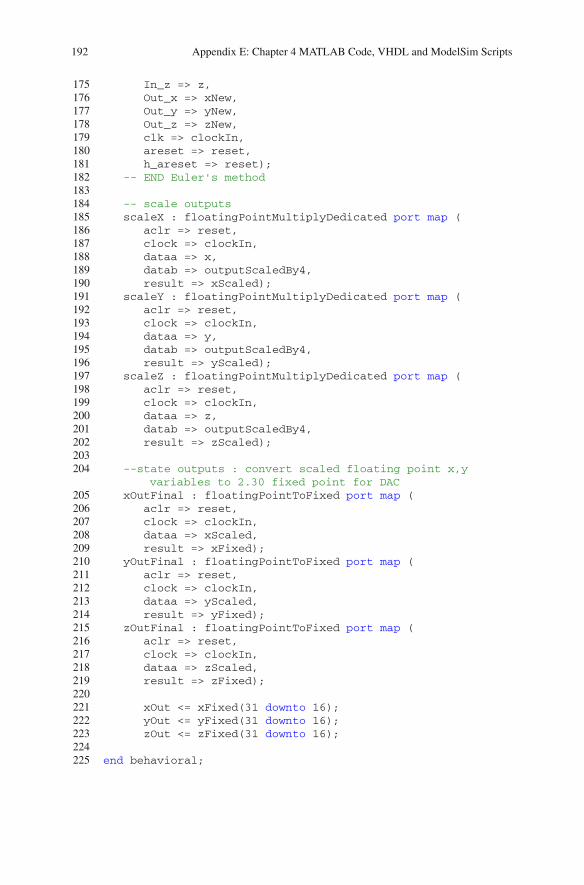
192 Appendix E: Chapter 4 MATLAB Code, VHDL and ModelSim Scripts
175 In_z => z,176 Out_x => xNew,177 Out_y => yNew,178 Out_z => zNew,179 clk => clockIn,180 areset => reset,181 h_areset => reset);182 -- END Euler's method183184 -- scale outputs185 scaleX : floatingPointMultiplyDedicated port map (186 aclr => reset,187 clock => clockIn,188 dataa => x,189 datab => outputScaledBy4,190 result => xScaled);191 scaleY : floatingPointMultiplyDedicated port map (192 aclr => reset,193 clock => clockIn,194 dataa => y,195 datab => outputScaledBy4,196 result => yScaled);197 scaleZ : floatingPointMultiplyDedicated port map (198 aclr => reset,199 clock => clockIn,200 dataa => z,201 datab => outputScaledBy4,202 result => zScaled);203204 --state outputs : convert scaled floating point x,y
variables to 2.30 fixed point for DAC205 xOutFinal : floatingPointToFixed port map (206 aclr => reset,207 clock => clockIn,208 dataa => xScaled,209 result => xFixed);210 yOutFinal : floatingPointToFixed port map (211 aclr => reset,212 clock => clockIn,213 dataa => yScaled,214 result => yFixed);215 zOutFinal : floatingPointToFixed port map (216 aclr => reset,217 clock => clockIn,218 dataa => zScaled,219 result => zFixed);220221 xOut <= xFixed(31 downto 16);222 yOut <= yFixed(31 downto 16);223 zOut <= zFixed(31 downto 16);224225 end behavioral;

Appendix FChapter 5 VHDL
F.1 Flip-Flops in VHDL
Listing F.1 VHDL specification of D flip-flop with asynchronous reset1 library ieee;2 use ieee.std_logic_1164.all;34 entity dFlipFlopWithAsyncReset is port (5 clock,reset : in std_logic;6 d : in std_logic_vector(31 downto 0);7 q : out std_logic_vector(31 downto 0));8 end dFlipFlopWithAsyncReset;910 architecture structuralDFlipFlop of dFlipFlopWithAsyncReset
is1112 begin13 process (clock,reset)14 begin15 if reset = '1' then16 q <= X"00000000";17 else18 if rising_edge(clock) then19 q <= d;20 end if;21 end if;22 end process;2324 end structuralDFlipFlop;
© Springer International Publishing Switzerland 2015B. Muthuswamy and S. Banerjee, A Route to Chaos Using FPGAs, Emergence,Complexity and Computation 16, DOI 10.1007/978-3-319-18105-9
193
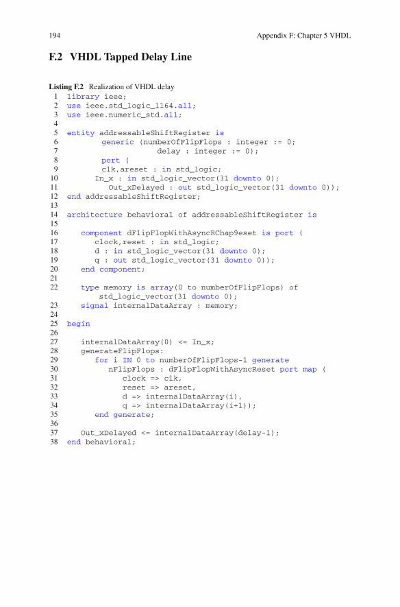
194 Appendix F: Chapter 5 VHDL
F.2 VHDL Tapped Delay Line
Listing F.2 Realization of VHDL delay1 library ieee;2 use ieee.std_logic_1164.all;3 use ieee.numeric_std.all;45 entity addressableShiftRegister is6 generic (numberOfFlipFlops : integer := 0;7 delay : integer := 0);8 port (9 clk,areset : in std_logic;10 In_x : in std_logic_vector(31 downto 0);11 Out_xDelayed : out std_logic_vector(31 downto 0));12 end addressableShiftRegister;1314 architecture behavioral of addressableShiftRegister is1516 component dFlipFlopWithAsyncRChap9eset is port (17 clock,reset : in std_logic;18 d : in std_logic_vector(31 downto 0);19 q : out std_logic_vector(31 downto 0));20 end component;2122 type memory is array(0 to numberOfFlipFlops) of
std_logic_vector(31 downto 0);23 signal internalDataArray : memory;2425 begin2627 internalDataArray(0) <= In_x;28 generateFlipFlops:29 for i IN 0 to numberOfFlipFlops-1 generate30 nFlipFlops : dFlipFlopWithAsyncReset port map (31 clock => clk,32 reset => areset,33 d => internalDataArray(i),34 q => internalDataArray(i+1));35 end generate;3637 Out_xDelayed <= internalDataArray(delay-1);38 end behavioral;
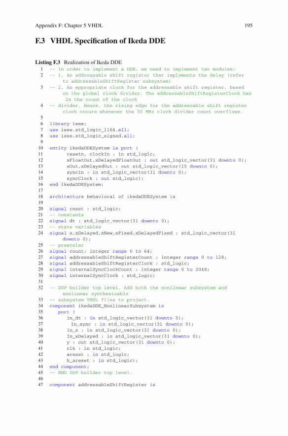
Appendix F: Chapter 5 VHDL 195
F.3 VHDL Specification of Ikeda DDE
Listing F.3 Realization of Ikeda DDE1 -- In order to implement a DDE, we need to implement two modules:2 -- 1. An addressable shift register that implements the delay (refer
to addressableShiftRegister subsystem)3 -- 2. An appropriate clock for the addressable shift register, based
on the global clock divider. The addressableShiftRegisterClock has2x the count of the clock
4 -- divider. Hence, the rising edge for the addressable shift registerclock occurs whenever the 50 MHz clock divider count overflows.
56 library ieee;7 use ieee.std_logic_1164.all;8 use ieee.std_logic_signed.all;910 entity ikedaDDESystem is port (11 resetn, clockIn : in std_logic;12 xFloatOut,xDelayedFloatOut : out std_logic_vector(31 downto 0);13 xOut,xDelayedOut : out std_logic_vector(15 downto 0);14 syncIn : in std_logic_vector(31 downto 0);15 syncClock : out std_logic);16 end ikedaDDESystem;1718 architecture behavioral of ikedaDDESystem is1920 signal reset : std_logic;21 -- constants22 signal dt : std_logic_vector(31 downto 0);23 -- state variables24 signal x,xDelayed,xNew,xFixed,xDelayedFixed : std_logic_vector(31
downto 0);25 -- prescalar26 signal count: integer range 0 to 64;27 signal addressableShiftRegisterCount : integer range 0 to 128;28 signal addressableShiftRegisterClock : std_logic;29 signal internalSyncClockCount : integer range 0 to 2048;30 signal internalSyncClock : std_logic;3132 -- DSP builder top level. Add both the nonlinear subsystem and
nonlinear synthesizable33 -- subsystem VHDL files to project.34 component ikedaDDE_NonlinearSubsystem is35 port (36 In_dt : in std_logic_vector(31 downto 0);37 In_sync : in std_logic_vector(31 downto 0);38 In_x : in std_logic_vector(31 downto 0);39 In_xDelayed : in std_logic_vector(31 downto 0);40 y : out std_logic_vector(31 downto 0);41 clk : in std_logic;42 areset : in std_logic;43 h_areset : in std_logic);44 end component;45 -- END DSP builder top level.4647 component addressableShiftRegister is

196 Appendix F: Chapter 5 VHDL
48 generic (numberOfFlipFlops : integer := 0;49 delay : integer := 0);50 port (51 clk,areset : in std_logic;52 In_x : in std_logic_vector(31 downto 0);53 Out_xDelayed : out std_logic_vector(31 downto 0));54 end component;555657 -- latency : 6 clock cycles58 component floatingPointToFixed IS59 PORT60 (61 aclr : IN STD_LOGIC ;62 clock : IN STD_LOGIC ;63 dataa : IN STD_LOGIC_VECTOR (31 DOWNTO 0);64 result : OUT STD_LOGIC_VECTOR (31 DOWNTO 0)65 );66 END component;6768 begin69 reset <= not resetn;70 -- Euler's method71 -- We first synchronously update state variables at 781.250 KHz (64
counts of 50 MHz clock)72 -- Since dt = 1/1024, time scale is actually (781.250e3/1024) = 762
Hz (approximately)73 -- state memory74 process(clockIn, resetn)75 begin76 -- constants (place outside reset and clock to avoid latches
)77 dt <= X"3A800000"; -- 1/102478 if resetn = '0' then79 -- initial state80 x <= X"3DCCCCCC";-- 0.181 count <= 0;82 addressableShiftRegisterCount <= 0;83 addressableShiftRegisterClock <= '0';84 else85 if rising_edge(clockIn) then8687 if count = 64 then88 count <= 0;89 else90 count <= count + 1;91 end if;9293 if count = 63 then94 x <= xNew;95 end if;9697 if addressableShiftRegisterCount = 128 then98 addressableShiftRegisterCount <= 0;99 else100 addressableShiftRegisterCount <=
addressableShiftRegisterCount + 1;
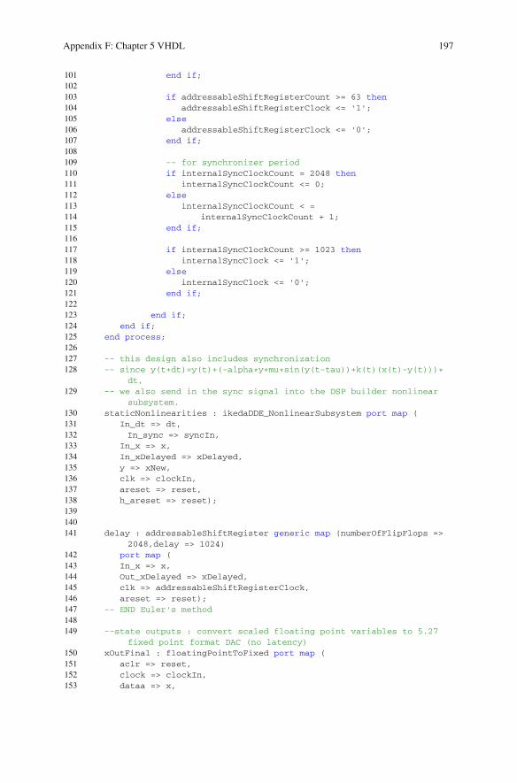
Appendix F: Chapter 5 VHDL 197
101 end if;102103 if addressableShiftRegisterCount >= 63 then104 addressableShiftRegisterClock <= '1';105 else106 addressableShiftRegisterClock <= '0';107 end if;108109 -- for synchronizer period110 if internalSyncClockCount = 2048 then111 internalSyncClockCount <= 0;112 else113 internalSyncClockCount < =114 internalSyncClockCount + 1;115 end if;116117 if internalSyncClockCount >= 1023 then118 internalSyncClock <= '1';119 else120 internalSyncClock <= '0';121 end if;122123 end if;124 end if;125 end process;126127 -- this design also includes synchronization128 -- since y(t+dt)=y(t)+(-alpha*y+mu*sin(y(t-tau))+k(t)(x(t)-y(t)))*
dt,129 -- we also send in the sync signal into the DSP builder nonlinear
subsystem.130 staticNonlinearities : ikedaDDE_NonlinearSubsystem port map (131 In_dt => dt,132 In_sync => syncIn,133 In_x => x,134 In_xDelayed => xDelayed,135 y => xNew,136 clk => clockIn,137 areset => reset,138 h_areset => reset);139140141 delay : addressableShiftRegister generic map (numberOfFlipFlops =>
2048,delay => 1024)142 port map (143 In_x => x,144 Out_xDelayed => xDelayed,145 clk => addressableShiftRegisterClock,146 areset => reset);147 -- END Euler's method148149 --state outputs : convert scaled floating point variables to 5.27
fixed point format DAC (no latency)150 xOutFinal : floatingPointToFixed port map (151 aclr => reset,152 clock => clockIn,153 dataa => x,

198 Appendix F: Chapter 5 VHDL
154 result => xFixed);155 xDelayedOutFinal : floatingPointToFixed port map (156 aclr => reset,157 clock => clockIn,158 dataa => xDelayed,159 result => xDelayedFixed);160161 xOut <= xFixed(31 downto 16);162 xDelayedOut <= xDelayedFixed(31 downto 16);163164 xFloatOut <= x;165 xDelayedFloatOut <= xDelayed;166 syncClock <= internalSyncClock;167 end behavioral;
F.4 VHDL Specification of DDEwith Sigmoidal Nonlinearity
Listing F.4 Realization of Sigmoidal DDE1 library ieee;2 use ieee.std_logic_1164.all;3 use ieee.std_logic_signed.all;45 entity sigmoidDDESystem is port (6 resetn, clockIn : in std_logic;7 xFloatOut,xDelayedFloatOut : out std_logic_vector(31 downto 0);8 xOut,xDelayedOut : out std_logic_vector(15 downto 0);9 syncIn : in std_logic_vector(31 downto 0);10 syncClock : out std_logic);11 end sigmoidDDESystem;1213 architecture behavioral of sigmoidDDESystem is1415 signal reset : std_logic;16 -- constants17 signal dt : std_logic_vector(31 downto 0);18 -- state variables19 signal x,xDelayed,xNew,xFixed,xDelayedFixed : std_logic_vector(31
downto 0);20 -- prescalar21 signal count: integer range 0 to 64;22 signal addressableShiftRegisterCount : integer range 0 to 128;23 signal addressableShiftRegisterClock : std_logic;24 signal internalSyncClockCount : integer range 0 to 2048;25 signal internalSyncClock : std_logic;2627 -- DSP builder top level. Add both the nonlinear subsystem and
nonlinear synthesizable28 -- subsystem VHDL files to project.29 component sigmoidalDDE_NonlinearSubsystem is30 port (31 In_dt : in std_logic_vector(31 downto 0);32 In_sync : in std_logic_vector(31 downto 0);

Appendix F: Chapter 5 VHDL 199
33 In_x : in std_logic_vector(31 downto 0);34 In_xDelayed : in std_logic_vector(31 downto 0);35 y : out std_logic_vector(31 downto 0);36 clk : in std_logic;37 areset : in std_logic;38 h_areset : in std_logic39 );40 end component;41 -- END DSP builder top level.4243 component addressableShiftRegister is44 generic (numberOfFlipFlops : integer := 0;45 delay : integer := 0);46 port (47 clk,areset : in std_logic;48 In_x : in std_logic_vector(31 downto 0);49 Out_xDelayed : out std_logic_vector(31 downto 0));50 end component;515253 -- latency : 6 clock cycles54 component floatingPointToFixed IS55 PORT56 (57 aclr : IN STD_LOGIC ;58 clock : IN STD_LOGIC ;59 dataa : IN STD_LOGIC_VECTOR (31 DOWNTO 0);60 result : OUT STD_LOGIC_VECTOR (31 DOWNTO 0)61 );62 END component;6364 begin65 reset <= not resetn;66 -- Euler's method67 -- We first synchronously update state variables at 3.125 MHz (16
counts of 50 MHz clock)68 -- Since dt = 1/1000, time scale is actually (3.125e6/1000) = 3.125
kHz (approximately)69 -- state memory70 process(clockIn, resetn)71 begin72 -- constants (place outside reset and clock to avoid latches
)73 dt <= X"3A83126E"; -- 1/100074 if resetn = '0' then75 -- initial state76 x <= X"3DCCCCCC";-- 0.177 count <= 0;78 addressableShiftRegisterCount <= 0;79 addressableShiftRegisterClock <= '0';80 else81 if rising_edge(clockIn) then8283 if count = 16 then84 count <= 0;85 else86 count <= count + 1;
200 Appendix F: Chapter 5 VHDL
87 end if;8889 if count = 15 then90 x <= xNew;91 end if;9293 if addressableShiftRegisterCount = 16 then94 addressableShiftRegisterCount <= 0;95 else96 addressableShiftRegisterCount <=
addressableShiftRegisterCount + 1;97 end if;9899 if addressableShiftRegisterCount >= 7 then100 addressableShiftRegisterClock <= '1';101 else102 addressableShiftRegisterClock <= '0';103 end if;104105 -- for synchronizer period106 if internalSyncClockCount = 2048 then107 internalSyncClockCount <= 0;108 else109 internalSyncClockCount < =110 internalSyncClockCount + 1;111 end if;112113 if internalSyncClockCount >= 1023 then114 internalSyncClock <= '1';115 else116 internalSyncClock <= '0';117 end if;118119 end if;120 end if;121 end process;122123 -- this design also includes synchronization, so we also send in
the sync signal into the DSP builder nonlinear subsystem.124 staticNonlinearities : sigmoidalDDE_NonlinearSubsystem port map (125 In_dt => dt,126 In_sync => syncIn,127 In_x => x,128 In_xDelayed => xDelayed,129 y => xNew,130 clk => clockIn,131 areset => reset,132 h_areset => reset);133134 delay : addressableShiftRegister generic map (numberOfFlipFlops =>
4096,delay => 3000)135 port map (136 In_x => x,137 Out_xDelayed => xDelayed,138 clk => addressableShiftRegisterClock,139 areset => reset);140 -- END Euler's method

Appendix F: Chapter 5 VHDL 201
141142 --state outputs : convert scaled floating point variables to 5.27
fixed point format DAC (no latency)143 xOutFinal : floatingPointToFixed port map (144 aclr => reset,145 clock => clockIn,146 dataa => x,147 result => xFixed);148 xDelayedOutFinal : floatingPointToFixed port map (149 aclr => reset,150 clock => clockIn,151 dataa => xDelayed,152 result => xDelayedFixed);153154 xOut <= xFixed(31 downto 16);155 xDelayedOut <= xDelayedFixed(31 downto 16);156157 xFloatOut <= x;158 xDelayedFloatOut <= xDelayed;159 syncClock <= internalSyncClock;160 end behavioral;
F.5 VHDL Specification of DDE with Signum Nonlinearity
Listing F.5 Realization of Signum DDE1 library ieee;2 use ieee.std_logic_1164.all;3 use ieee.std_logic_signed.all;45 entity signumDDESystem is port (6 resetn, clockIn : in std_logic;7 xFloatOut,xDelayedFloatOut : out std_logic_vector(31 downto 0);8 xOut,xDelayedOut : out std_logic_vector(15 downto 0);9 syncIn : in std_logic_vector(31 downto 0);
10 syncClock : out std_logic);11 end signumDDESystem;1213 architecture behavioral of signumDDESystem is1415 signal reset : std_logic;16 -- constants17 signal dt : std_logic_vector(31 downto 0);18 -- state variables19 signal x,xDelayed,xNew,xFixed,xDelayedFixed,f1,f2,f : std_logic_vector
(31 downto 0);20 -- prescalar21 signal count: integer range 0 to 64;22 signal addressableShiftRegisterCount : integer range 0 to 128;23 signal addressableShiftRegisterClock : std_logic;24 signal internalSyncClockCount : integer range 0 to 2048;25 signal internalSyncClock : std_logic;26
202 Appendix F: Chapter 5 VHDL
27 -- We do not use DSP builder for the signum system since the signumfunction is very easy to implement:
28 -- from http://en.wikipedia.org/wiki/Single-precision_floating-point_format
29 -- sign bit is MSb, +0 = 0x00000000, -0 = 0x8000000030 -- System: x'=sgn(x(t-2))-x(t-2), x(t <= 0) = 0.131 signal isZero,signbit : std_logic;32 signal signbitOut : std_logic_vector(31 downto 0);3334 component addressableShiftRegister is35 generic (numberOfFlipFlops : integer := 0;36 delay : integer := 0);37 port (38 clk,areset : in std_logic;39 In_x : in std_logic_vector(31 downto 0);40 Out_xDelayed : out std_logic_vector(31 downto 0));41 end component;424344 -- latency : 6 clock cycles45 component floatingPointToFixed IS46 PORT47 (48 aclr : IN STD_LOGIC ;49 clock : IN STD_LOGIC ;50 dataa : IN STD_LOGIC_VECTOR (31 DOWNTO 0);51 result : OUT STD_LOGIC_VECTOR (31 DOWNTO 0)52 );53 END component;5455 -- add_sub = '1' for addition, else subtraction56 component floatingPointAddSubtract IS57 PORT58 (59 aclr : IN STD_LOGIC ;60 add_sub : IN STD_LOGIC ;61 clk_en : IN STD_LOGIC ;62 clock : IN STD_LOGIC ;63 dataa : IN STD_LOGIC_VECTOR (31 DOWNTO 0);64 datab : IN STD_LOGIC_VECTOR (31 DOWNTO 0);65 result : OUT STD_LOGIC_VECTOR (31 DOWNTO 0)66 );67 END component;6869 component floatingPointMultiplyDedicated IS70 PORT71 (72 aclr : IN STD_LOGIC ;73 clock : IN STD_LOGIC ;74 dataa : IN STD_LOGIC_VECTOR (31 DOWNTO 0);75 datab : IN STD_LOGIC_VECTOR (31 DOWNTO 0);76 result : OUT STD_LOGIC_VECTOR (31 DOWNTO 0)77 );78 END component;7980 begin81 reset <= not resetn;
Appendix F: Chapter 5 VHDL 203
82 -- Euler's method83 -- We first synchronously update state variables at 3.125 MHz (16
counts of 50 MHz clock)84 -- Since dt = 1/1000, time scale is actually (3.125e6/1000) = 3.125
kHz (approximately)85 -- state memory86 process(clockIn, resetn)87 begin88 -- constants (place outside reset and clock to avoid
latches)89 dt <= X"3A83126E"; -- 1/100090 if resetn = '0' then91 -- initial state92 x <= X"3DCCCCCC";-- 0.193 count <= 0;94 addressableShiftRegisterCount <= 0;95 addressableShiftRegisterClock <= '0';96 else97 if rising_edge(clockIn) then9899 if count = 16 then
100 count <= 0;101 else102 count <= count + 1;103 end if;104105 if count = 15 then106 x <= xNew;107 end if;108109 if addressableShiftRegisterCount = 16 then110 addressableShiftRegisterCount <= 0;111 else112 addressableShiftRegisterCount <=
addressableShiftRegisterCount + 1;113 end if;114115 if addressableShiftRegisterCount >= 7 then116 addressableShiftRegisterClock <= '1';117 else118 addressableShiftRegisterClock <= '0';119 end if;120121 -- for synchronizer period122 if internalSyncClockCount = 2048 then123 internalSyncClockCount <= 0;124 else125 internalSyncClockCount <=126 internalSyncClockCount + 1;127 end if;128129 if internalSyncClockCount >= 1023 then130 internalSyncClock <= '1';131 else132 internalSyncClock <= '0';133 end if;134
204 Appendix F: Chapter 5 VHDL
135 end if;136 end if;137 end process;138139 -- this design could include synchronization140 delay : addressableShiftRegister generic map (numberOfFlipFlops =>
4096,delay => 2000)141 port map (142 In_x => x,143 Out_xDelayed => xDelayed,144 clk => addressableShiftRegisterClock,145 areset => reset);146147 -- compute f1=sgn(x(t-2))148 with xDelayed select149 isZero <= '1' when X"00000000",150 '1' when X"80000000",151 '0' when others;152 signBit <= xDelayed(31);153 with signBit select154 signBitOut <= X"3F800000" when '0', -- +1155 X"BF800000" when others; -- -1156 with isZero select157 f1 <= signBitOut when '0',158 X"00000000" when others;159160 -- compute f2=sgn(x(t-2))-x(t-2)=f1-xDelayed161 f2Out : floatingPointAddSubtract port map (162 aclr => reset,163 add_sub => '0',164 clk_en => '1',165 clock => clockIn,166 dataa => f1,167 datab => xDelayed,168 result => f2);169170 -- compute f=f2*dt171 fOut : floatingPointMultiplyDedicated port map (172 aclr => reset,173 clock => clockIn,174 dataa => f2,175 datab => dt,176 result => f);177 -- compute xNew = x+f178 xNewOut : floatingPointAddSubtract port map (179 aclr => reset,180 add_sub => '1',181 clk_en => '1',182 clock => clockIn,183 dataa => x,184 datab => f,185 result => xNew);186 -- END Euler's method187188 --state outputs : convert scaled floating point variables to 5.27
fixed point format DAC (no latency)189 xOutFinal : floatingPointToFixed port map (
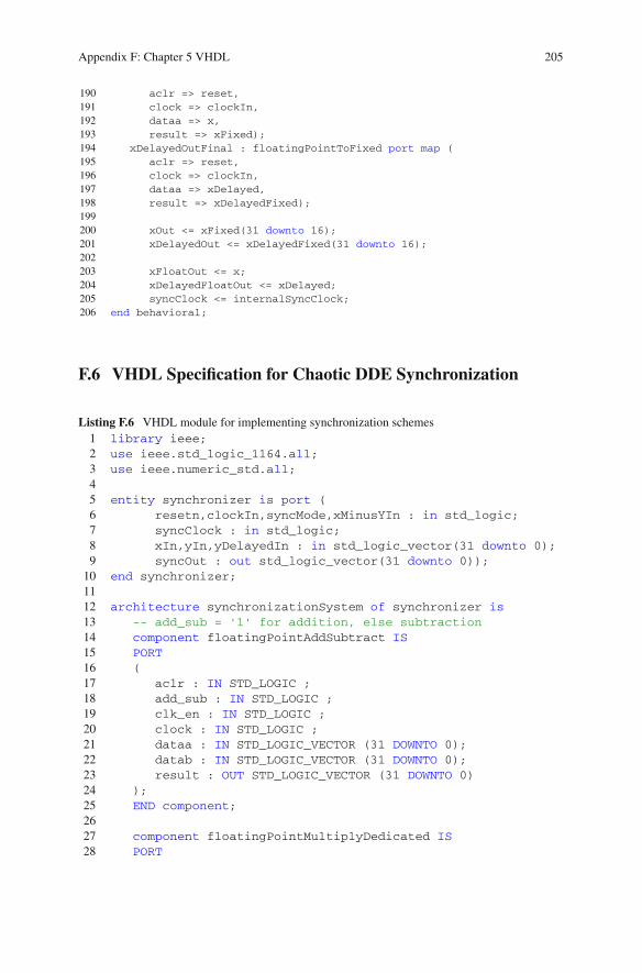
Appendix F: Chapter 5 VHDL 205
190 aclr => reset,191 clock => clockIn,192 dataa => x,193 result => xFixed);194 xDelayedOutFinal : floatingPointToFixed port map (195 aclr => reset,196 clock => clockIn,197 dataa => xDelayed,198 result => xDelayedFixed);199200 xOut <= xFixed(31 downto 16);201 xDelayedOut <= xDelayedFixed(31 downto 16);202203 xFloatOut <= x;204 xDelayedFloatOut <= xDelayed;205 syncClock <= internalSyncClock;206 end behavioral;
F.6 VHDL Specification for Chaotic DDE Synchronization
Listing F.6 VHDL module for implementing synchronization schemes1 library ieee;2 use ieee.std_logic_1164.all;3 use ieee.numeric_std.all;45 entity synchronizer is port (6 resetn,clockIn,syncMode,xMinusYIn : in std_logic;7 syncClock : in std_logic;8 xIn,yIn,yDelayedIn : in std_logic_vector(31 downto 0);9 syncOut : out std_logic_vector(31 downto 0));
10 end synchronizer;1112 architecture synchronizationSystem of synchronizer is13 -- add_sub = '1' for addition, else subtraction14 component floatingPointAddSubtract IS15 PORT16 (17 aclr : IN STD_LOGIC ;18 add_sub : IN STD_LOGIC ;19 clk_en : IN STD_LOGIC ;20 clock : IN STD_LOGIC ;21 dataa : IN STD_LOGIC_VECTOR (31 DOWNTO 0);22 datab : IN STD_LOGIC_VECTOR (31 DOWNTO 0);23 result : OUT STD_LOGIC_VECTOR (31 DOWNTO 0)24 );25 END component;2627 component floatingPointMultiplyDedicated IS28 PORT

206 Appendix F: Chapter 5 VHDL
29 (30 aclr : IN STD_LOGIC ;31 clock : IN STD_LOGIC ;32 dataa : IN STD_LOGIC_VECTOR (31 DOWNTO 0);33 datab : IN STD_LOGIC_VECTOR (31 DOWNTO 0);34 result : OUT STD_LOGIC_VECTOR (31 DOWNTO 0)35 );36 END component;3738 component floatingPointCos IS39 PORT40 (41 aclr : IN STD_LOGIC ;42 clock : IN STD_LOGIC ;43 data : IN STD_LOGIC_VECTOR (31 DOWNTO 0);44 result : OUT STD_LOGIC_VECTOR (31 DOWNTO 0)45 );46 END component;4748 component floatingPointAbs IS49 PORT50 (51 aclr : IN STD_LOGIC ;52 data : IN STD_LOGIC_VECTOR (31 DOWNTO 0);53 result : OUT STD_LOGIC_VECTOR (31 DOWNTO 0)54 );55 END component;5657 signal reset : std_logic;58 signal xMinusY,yMinusX,kTimesXMinusY,kTimesYMinusX,
kSquareWaveTimesXMinusY,kSquareWaveTimesYMinusX,kCosineTimesXMinusY,kCosineTimesYMinusX :std_logic_vector(31 downto 0);
59 signal cosineOut,absOut,k1,cosCoupling : std_logic_vector(31 downto 0);
60 signal k,alpha,twoTimesMu : std_logic_vector(31 downto 0);
61 begin62 reset <= not resetn;63 alpha <= X"40A00000"; -- alpha = 564 twoTimesMu <= X"42200000"; -- two*mu = 2*20 = 4065 -- generate x-y and y-x using megaWizard. We chose to use
the megaWizard because DSP builder is too much effortfor something as simple as floating point subtraction
66 xMinusYInstance : floatingPointAddSubtract port map (67 aclr => reset,68 add_sub => '0', -- dataa - datab69 clk_en => '1',70 clock => clockIn,71 dataa => xIn,72 datab => yIn,
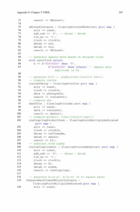
Appendix F: Chapter 5 VHDL 207
73 result => XMinusY);7475 yMinusXInstance : floatingPointAddSubtract port map (76 aclr => reset,77 add_sub => '0', -- dataa - datab78 clk_en => '1',79 clock => clockIn,80 dataa => yIn,81 datab => xIn,82 result => YMinusX);8384 -- generate square wave based on delayed clock85 with syncClock select86 k <= X"00000000" when '0',87 X"42480000" when others; -- square wave
amplitude is 508889 -- generate k(t) = -alpha+2*mu*|cos(y(t-tau))|90 -- compute cosine91 cosineYDelay : floatingPointCos port map (92 aclr => reset,93 clock => clockIn,94 data => yDelayedIn,95 result => cosineOut);96 -- compute abs97 absOfCos : floatingPointAbs port map (98 aclr => reset,99 data => cosineOut,100 result => absOut);101 -- compute product: 2*mu*|cos(y(t-tau))|102 cosCouplingProductTerm : floatingPointMultiplyDedicated
port map (103 aclr => reset,104 clock => clockIn,105 dataa => twoTimesMu,106 datab => absOut,107 result => k1);108 -- subtract from alpha109 cosineCouplingOut : floatingPointAddSubtract port map (110 aclr => reset,111 add_sub => '0', -- dataa - datab112 clk_en => '1',113 clock => clockIn,114 dataa => k1,115 datab => alpha,116 result => cosCoupling);117118 -- generate k*(x-y), k*(y-x) (k is square wave)119 kSquareWaveTimesXMinusYInstance :
floatingPointMultiplyDedicated port map (120 aclr => reset,
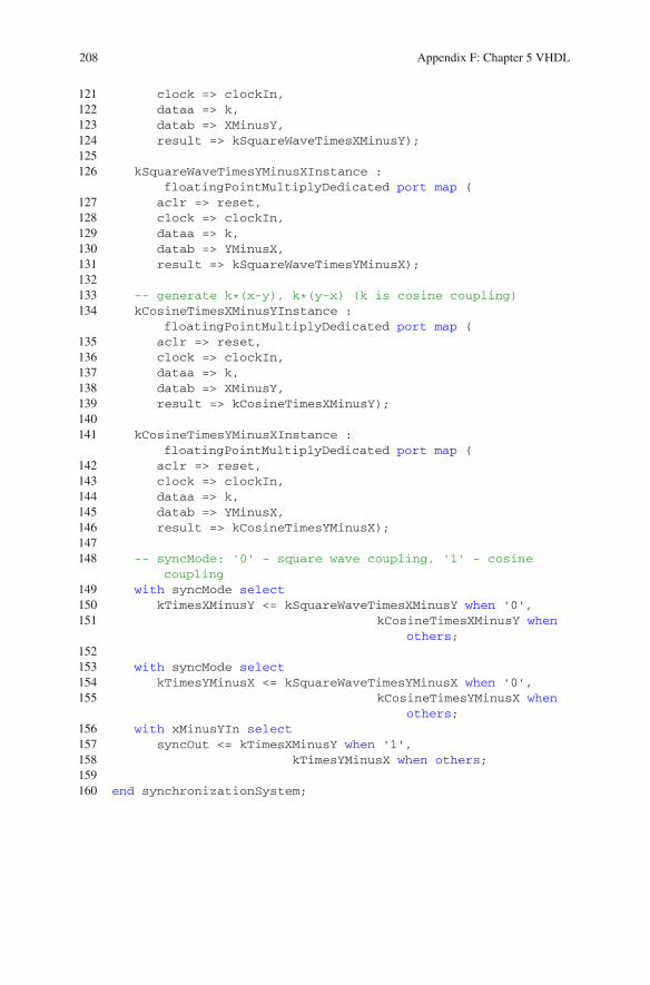
208 Appendix F: Chapter 5 VHDL
121 clock => clockIn,122 dataa => k,123 datab => XMinusY,124 result => kSquareWaveTimesXMinusY);125126 kSquareWaveTimesYMinusXInstance :
floatingPointMultiplyDedicated port map (127 aclr => reset,128 clock => clockIn,129 dataa => k,130 datab => YMinusX,131 result => kSquareWaveTimesYMinusX);132133 -- generate k*(x-y), k*(y-x) (k is cosine coupling)134 kCosineTimesXMinusYInstance :
floatingPointMultiplyDedicated port map (135 aclr => reset,136 clock => clockIn,137 dataa => k,138 datab => XMinusY,139 result => kCosineTimesXMinusY);140141 kCosineTimesYMinusXInstance :
floatingPointMultiplyDedicated port map (142 aclr => reset,143 clock => clockIn,144 dataa => k,145 datab => YMinusX,146 result => kCosineTimesYMinusX);147148 -- syncMode: '0' - square wave coupling, '1' - cosine
coupling149 with syncMode select150 kTimesXMinusY <= kSquareWaveTimesXMinusY when '0',151 kCosineTimesXMinusY when
others;152153 with syncMode select154 kTimesYMinusX <= kSquareWaveTimesYMinusX when '0',155 kCosineTimesYMinusX when
others;156 with xMinusYIn select157 syncOut <= kTimesXMinusY when '1',158 kTimesYMinusX when others;159160 end synchronizationSystem;

Appendix F: Chapter 5 VHDL 209
F.7 DE2 Chaotic DDE Specification Top Level
Listing F.7 VHDL top level for implementing synchronization scheme for DDEs1 -- DE2-115 Audio codec interface for analog chaotic signals output
from chaotic DDEs2 -- Reference design for EPJ-ST paper - "Synchronization in Coupled
Ikeda Delay Differential Equations : Experimental Observationsusing Field
3 -- Programmable Gate Arrays", Valli, D. et. al.4 -- i2c Audio codec interface courtesy of Stapleton, Colin, EE2902
Spring 2011, Milwaukee School of Engineering, 4/15/115 -- adc_dac interface courtesy of Chu, Embedded SOPC Design with
VHDL, pp. 545-546, 4/8/136 -- Based on chaos engine created by Dr. Muthuswamy (AY 2013-2014),
primarily for the book:7 -- "A Route to Chaos Using FPGAs - Volumes I and II"8 -- DSP builder based design9 -- IMPORTANT : NEED TO SET nCEO as regular I/O via Device and Pin
Options10 -- KEY(0): global reset11 -- KEY(1): bifurcation parameter control (see SW(2) below), but
this is not used in this design.12 -- SW(0) : loopback (switch down or SW(0)='0') or chaotic dynamics
(switch up or SW(0)='1' (default))13 -- SW(1) : select between drive (switch down or SW(0)='0') and sync
error signal (switch up or SW(0)='1', e(t) for square wave ison left-channel. e(t) for cosine on right channel)
14 -- SW(2) : bifurcation parameter decrement (switch down or SW(2) ='0') or increment (switch up or SW(2) = '1'
15 (default)). This is not used in this design.16 -- left channel data is controlled by SW(4 downto 3)17 -- right channel data is controlled by SW(6 downto 5)181920 LIBRARY ieee;21 USE ieee.std_logic_1164.all;22 USE ieee.std_logic_signed.all; -- need to subtract
std_logic_vectors for synchronization result2324 entity DE2ChaoticDDEs is25 port(26 KEY: in std_logic_vector(3 downto 0);27 CLOCK_50: in std_logic;28 --I2C ports29 I2C_SCLK: out std_logic;30 I2C_SDAT: inout std_logic;31 --audio codec ports32 AUD_ADCDAT: in std_logic;33 AUD_ADCLRCK: out std_logic;34 AUD_DACLRCK: out std_logic;35 AUD_DACDAT: out std_logic;36 AUD_XCK: out std_logic;37 AUD_BCLK: out std_logic;38 --select loopback test or neuron model output
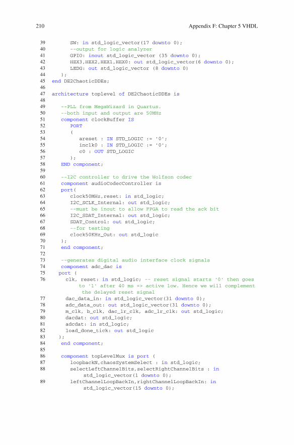
210 Appendix F: Chapter 5 VHDL
39 SW: in std_logic_vector(17 downto 0);40 --output for logic analyzer41 GPIO: inout std_logic_vector (35 downto 0);42 HEX3,HEX2,HEX1,HEX0: out std_logic_vector(6 downto 0);43 LEDG: out std_logic_vector (8 downto 0)44 );45 end DE2ChaoticDDEs;4647 architecture toplevel of DE2ChaoticDDEs is4849 --PLL from MegaWizard in Quartus.50 --both input and output are 50MHz51 component clockBuffer IS52 PORT53 (54 areset : IN STD_LOGIC := '0';55 inclk0 : IN STD_LOGIC := '0';56 c0 : OUT STD_LOGIC57 );58 END component;5960 --I2C controller to drive the Wolfson codec61 component audioCodecController is62 port(63 clock50MHz,reset: in std_logic;64 I2C_SCLK_Internal: out std_logic;65 --must be inout to allow FPGA to read the ack bit66 I2C_SDAT_Internal: out std_logic;67 SDAT_Control: out std_logic;68 --for testing69 clock50KHz_Out: out std_logic70 );71 end component;7273 --generates digital audio interface clock signals74 component adc_dac is75 port (76 clk, reset: in std_logic; -- reset signal starts '0' then goes
to '1' after 40 ms => active low. Hence we will complementthe delayed reset signal
77 dac_data_in: in std_logic_vector(31 downto 0);78 adc_data_out: out std_logic_vector(31 downto 0);79 m_clk, b_clk, dac_lr_clk, adc_lr_clk: out std_logic;80 dacdat: out std_logic;81 adcdat: in std_logic;82 load_done_tick: out std_logic83 );84 end component;8586 component topLevelMux is port (87 loopbackN,chaosSystemSelect : in std_logic;88 selectLeftChannelBits,selectRightChannelBits : in
std_logic_vector(1 downto 0);89 leftChannelLoopBackIn,rightChannelLoopBackIn: in
std_logic_vector(15 downto 0);

Appendix F: Chapter 5 VHDL 211
90 chaosX1,chaosY1,chaosZ1,chaosX2,chaosY2,chaosZ2 : instd_logic_vector(15 downto 0);
91 leftChannelDACRegister,rightChannelDACRegister : outstd_logic_vector(15 downto 0));
92 end component;9394 component pulseFSM is port (95 reset,clock,trigger : in std_logic;96 pulseOut : out std_logic);97 end component;9899 -- Chaotic system. DSP builder static nonlinearity interface is
inside the module.100 -- The ikeda DDE subsystem can also implement synchronization101 component ikedaDDESystem is port (102 resetn, clockIn : in std_logic;103 xFloatOut,xDelayedFloatOut : out std_logic_vector(31 downto
0);104 xOut,xDelayedOut : out std_logic_vector(15 downto 0);105 syncIn : in std_logic_vector(31 downto 0);106 syncClock : out std_logic);107 end component;108109 component sigmoidDDESystem is port (110 resetn, clockIn : in std_logic;111 xFloatOut,xDelayedFloatOut : out std_logic_vector(31 downto
0);112 xOut,xDelayedOut : out std_logic_vector(15 downto 0);113 syncIn : in std_logic_vector(31 downto 0);114 syncClock : out std_logic);115 end component;116117 component signumDDESystem is port (118 resetn, clockIn : in std_logic;119 xFloatOut,xDelayedFloatOut : out std_logic_vector(31 downto
0);120 xOut,xDelayedOut : out std_logic_vector(15 downto 0);121 syncIn : in std_logic_vector(31 downto 0);122 syncClock : out std_logic);123 end component;124125 component synchronizer is port (126 resetn,clockIn,syncMode,xMinusYIn,syncClock : in std_logic;127 xIn,yIn,yDelayedIn : in std_logic_vector(31 downto 0);128 syncOut : out std_logic_vector(31 downto 0));129 end component;130 -- end dsp builder top level131132 --clock signal from the PLL clockBuffer133 signal clock50MHz : std_logic;134135 --asynchronous reset for the whole project136 signal reset: std_logic;137138 --I2C data and clock lines
212 Appendix F: Chapter 5 VHDL
139 signal i2cData, i2cClock: std_logic;140141 --tri-state buffer control142 signal i2cDataControl: std_logic;143 signal i2cDataTriState: std_logic;144145 --assert signal from delay counter146 signal codecReset,codecResetn: std_logic;147148 --audio codec signals149 signal clock18MHz : std_logic;150 signal adcDat_sig: std_logic;151 signal adcLRCK_sig: std_logic;152 signal dacLRCK_sig: std_logic;153 signal dacDat_sig: std_logic;154 signal bck_sig: std_logic;155 signal dac_data_in,adc_data_out : std_logic_vector(31 downto 0);156157 --nonlinear dynamics model signals158 signal leftChannelDataRegister,leftChannelADCRegister,
leftChannelDACRegister : std_logic_vector(15 downto 0);159 signal rightChannelDataRegister,rightChannelADCRegister,
rightChannelDACRegister : std_logic_vector(15 downto 0);160 signal leftChannelChaos,rightChannelChaos : std_logic_vector(15
downto 0);161162 signal chaosXOut,chaosYOut,chaosZOut : std_logic_vector(15
downto 0);163 signal chaosX1,chaosY1,chaosZ1 : std_logic_vector(15 downto 0);164 signal chaosX2,chaosX2Temp,chaosY2,chaosZ2 : std_logic_vector(15
downto 0);165166 -- 32-bit single-precision floating point data for
synchronization167 signal chaosXFloatOut,chaosYFloatOut,chaosXDelayedFloatOut,
chaosYDelayedFloatOut,syncSignalXMinusY,syncSignalYMinusX :std_logic_vector(31 downto 0);
168 signal syncClock,syncClockTemp : std_logic;169170 signal trigger,pulseOut : std_logic;171172 -- testing173 signal clock50KHz : std_logic;174175 -- select signals176 signal selectBitsX,selectBitsY : std_logic_vector177 (1 downto 0);178 begin179180 --keys are active low181 reset <= not KEY(0);182183 --PLL184 clockBufferInstance: clockBuffer port map(reset,CLOCK_50,
clock50MHz);
Appendix F: Chapter 5 VHDL 213
185186 --I2C187 I2CControllerInstance: audioCodecController port map(clock50MHz,
reset, i2cClock, i2cData,i2cDataControl, clock50KHz);188189 --Codec Controller190 dac_data_in <= leftChannelDACRegister&rightChannelDACRegister;191 leftChannelADCRegister <= adc_data_out(31 downto 16);192 rightChannelADCRegister <= adc_data_out(15 downto 0);193 adcDacInterface : adc_dac port map (194 clk => clock50MHz,195 reset => reset,196 dac_data_in => dac_data_in,197 adc_data_out => adc_data_out,198 m_clk=>clock18MHz,199 b_clk => bck_sig,200 dac_lr_clk => dacLRCK_sig,201 adc_lr_clk => adcLRCK_sig,202 dacdat => dacDat_sig,203 adcdat => adcDat_sig,204 load_done_tick => open);205206 mulitplexers : topLevelMux port map (207 loopbackN => SW(0),208 chaosSystemSelect => SW(1),209 selectLeftChannelBits => SW(4 downto 3), -- SW(2) is used to
increment or decrement bifurcation parameter210 selectRightChannelBits => SW(6 downto 5),211 leftChannelLoopBackIn => leftChannelADCRegister,212 rightChannelLoopBackIn => rightChannelADCRegister,213 chaosX1 => chaosX1,214 chaosY1 => chaosY1,215 chaosZ1 => chaosZ1,216 chaosX2 => chaosX2,217 chaosY2 => chaosY2,218 chaosZ2 => chaosZ2,219 leftChannelDACRegister => leftChannelDACRegister,220 rightChannelDACRegister => rightChannelDACRegister);221222223 -- ------------------------ BEGIN DSP BUILDER BASED CHAOTIC
DYNAMICS224 -- IKEDA DDE SYNCHRONIZATION CURRENTLY DISABLED225 -- ikedaDDESystemInstance_drive : ikedaDDESystem port map (226 -- resetn => KEY(0),227 -- clockIn => clock50MHz,228 -- xFloatOut => chaosXFloatOut,229 -- xDelayedFloatOut => chaosXDelayedFloatOut,230 -- xOut => chaosX1,231 -- xDelayedOut => chaosY1,232 -- syncIn => X"00000000", -- k(t)*(y-x)233 -- syncClock => syncClock);234 -- chaosZ1 <= X"0000";235236 -- ikedaDDESystemInstance_Response : ikedaDDESystem port map (

214 Appendix F: Chapter 5 VHDL
237 -- resetn => KEY(0),238 -- clockIn => clock50MHz,239 -- xFloatOut => chaosYFloatOut,240 -- xDelayedFloatOut => chaosYDelayedFloatOut,241 -- xOut => chaosX2,242 -- xDelayedOut => chaosY2,243 -- syncIn => syncSignalXMinusY, -- k(t)*(x-y)244 -- syncClock => syncClockTemp);245 -- --chaosX2 <= chaosX1 - chaosX2Temp; -- synchronization error246 -- chaosZ2 <= X"0000";247248 --249 -- syncInstanceSquareXMinusY : synchronizer port map (250 -- resetn => KEY(0),251 -- clockIn => clock50MHz,252 -- syncMode => '0',253 -- xMinusYIn => '1',254 -- syncClock => syncClock,255 -- xIn => chaosXFloatOut,256 -- yIn => chaosYFloatOut,257 -- yDelayedIn => chaosYDelayedFloatOut,258 -- syncOut => syncSignalXMinusY);259 --260 -- syncInstanceSquareYMinusX : synchronizer port map (261 -- resetn => KEY(0),262 -- clockIn => clock50MHz,263 -- syncMode => '0',264 -- xMinusYIn => '0',265 -- syncClock => syncClock,266 -- xIn => chaosXFloatOut,267 -- yIn => chaosYFloatOut,268 -- yDelayedIn => chaosYDelayedFloatOut,269 -- syncOut => syncSignalYMinusX);270 --271272 sigmoidalDDE : sigmoidDDESystem port map (273 resetn => KEY(0),274 clockIn => clock50MHz,275 xFloatOut => chaosXFloatOut, -- unused276 xDelayedFloatOut => chaosXDelayedFloatOut,277 xOut => chaosX1,278 xDelayedOut => chaosY1,279 syncIn => X"00000000",280 syncClock => syncClock);281 chaosZ1 <= X"0000";282283 signumDDE : signumDDESystem port map (284 resetn => KEY(0),285 clockIn => clock50MHz,286 xFloatOut => chaosYFloatOut, -- unused287 xDelayedFloatOut => chaosYDelayedFloatOut,288 xOut => chaosX2,289 xDelayedOut => chaosY2,290 syncIn => X"00000000",291 syncClock => syncClockTemp);
Appendix F: Chapter 5 VHDL 215
292 chaosZ2 <= X"0000";293294 ------------------------ END DSP BUILDER CHAOTIC DYNAMICS295296 --tri-state data output297 i2cDataTriState <= i2cData when i2cDataControl = '1' else 'Z';298299 --I2C output ports300 I2C_SCLK <= i2cClock;301 I2C_SDAT <= i2cDataTriState;302303 --audio codec input port304 adcDat_sig <= AUD_ADCDAT;305306 --audio codec ouput ports307 AUD_ADCLRCK <= adcLRCK_sig;308 AUD_DACLRCK <= dacLRCK_sig;309 AUD_DACDAT <= dacDat_sig;310 AUD_XCK <= clock18MHz;311 AUD_BCLK <= bck_sig;312313 --for testing314 GPIO(5) <= adcLRCK_sig;315 GPIO(4) <= dacLRCK_sig;316 GPIO(3) <= bck_sig;317 GPIO(2) <= adcDat_sig;318 GPIO(1) <= dacDat_sig;319 GPIO(0) <= clock18MHz;320 LEDG(0) <= reset;321 LEDG(1) <= clock50KHz;322323324 HEX1 <= "1111111";325 HEX0 <= "1111111";326327 HEX2 <= "1111111";328 HEX3 <= "1111111";329330 end toplevel;
The synchronizer functionality for the Ikeda DDE is implemented in Lines 222–267 in listing F.7. We have commented out the functionality so that the reader canexperiment with synchronization.
1. Lines 222–244 define the Ikeda drive and response system.2. Lines 247–267 implement two synchronizer modules : one for square wave cou-
pling and the other for cosine coupling. Depending on the syncMode input, eithersquare wave or cosine coupling is selected (refer to listing F.6).
Within each DDE DSP builder specification, we have included a “syncIn” inputthat can be tied to ground for non-synchronous designs.
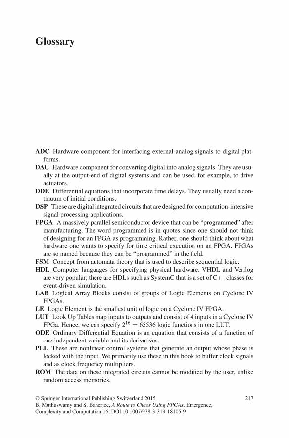
Glossary
ADC Hardware component for interfacing external analog signals to digital plat-forms.
DAC Hardware component for converting digital into analog signals. They are usu-ally at the output-end of digital systems and can be used, for example, to driveactuators.
DDE Differential equations that incorporate time delays. They usually need a con-tinuum of initial conditions.
DSP These are digital integrated circuits that are designed for computation-intensivesignal processing applications.
FPGA A massively parallel semiconductor device that can be “programmed” aftermanufacturing. The word programmed is in quotes since one should not thinkof designing for an FPGA as programming. Rather, one should think about whathardware one wants to specify for time critical execution on an FPGA. FPGAsare so named because they can be “programmed” in the field.
FSM Concept from automata theory that is used to describe sequential logic.HDL Computer languages for specifying physical hardware. VHDL and Verilog
are very popular; there are HDLs such as SystemC that is a set of C++ classes forevent-driven simulation.
LAB Logical Array Blocks consist of groups of Logic Elements on Cyclone IVFPGAs.
LE Logic Element is the smallest unit of logic on a Cyclone IV FPGA.LUT Look Up Tables map inputs to outputs and consist of 4 inputs in a Cyclone IV
FPGa. Hence, we can specify 216 = 65536 logic functions in one LUT.ODE Ordinary Differential Equation is an equation that consists of a function of
one independent variable and its derivatives.PLL These are nonlinear control systems that generate an output whose phase is
locked with the input. We primarily use these in this book to buffer clock signalsand as clock frequency multipliers.
ROM The data on these integrated circuits cannot be modified by the user, unlikerandom access memories.
© Springer International Publishing Switzerland 2015B. Muthuswamy and S. Banerjee, A Route to Chaos Using FPGAs, Emergence,Complexity and Computation 16, DOI 10.1007/978-3-319-18105-9
217

218 Glossary
RTL A design abstraction that models a synchronous digital circuit in terms of dataflow between hardware registers and logic operations.
SDC A language for specifying timing constraints.SDRAM A type of dynamic random access memory that is synchronized with a
system bus.SMA A type of coaxial connector used for frequencies typically from 0 to 18 GHz.VHDL Hardware description language that can also beused formixed-signal system
specification and a general purpose parallel programming language.
Solutions
For step-by-step solutions to all problems, please visit the book’s website:http://www.harpgroup.org/muthuswamy/ARouteToChaosUsingFPGAs/ARouteToChaosUsingFPGAs.html
© Springer International Publishing Switzerland 2015B. Muthuswamy and S. Banerjee, A Route to Chaos Using FPGAs, Emergence,Complexity and Computation 16, DOI 10.1007/978-3-319-18105-9
219