API-Std-625 (2010) Tank System for Rerigerated Liquefied Gas Storage
Standard Edition Section Inquiry # Question Reply
The cost of NDE/NDT inspection of some fasteners outweigh the cost to replace with
new. Since this is the case, many equipment owners and OEMs elect to replace many
types of fasteners based on visual inspection or time in service instead of paying to
inspect them. In the majority of cases, the OEM does not describe acceptance criteria
for used fasteners.
Does it meet the intent of 4.3.6 if the type of bolt NDE identified by an equipment
owner’s PM program is visual and bolts are replaced based on visual appearance,
torque checks and/or time in service?
Yes.
Question 1: In reference to API Standard 53 requirement 4.4.3, are pressure-
energized ring gaskets required for Surface BOP Choke Manifolds?
Reply 1: Yes.
It has been noted that there are requirements within the standard
(4.4.3 & 6.2.2.2) that are not requirements within the equipment
design specifications.
Question 2: Is API 6A, 16A and 16C considering change to the design requirements
based on the exclusion of non-pressure energized ring gaskets in API Standard 53
4.4.3?
Reply 2: This question falls outside the scope of S53 and does not
meet the requirements for submitting a technical inquiry. You may
consider submitting your question directly to each of the task groups
for the documents you reference in the question.
534th Edition,
Nov. 2012Section 6 53-15-17
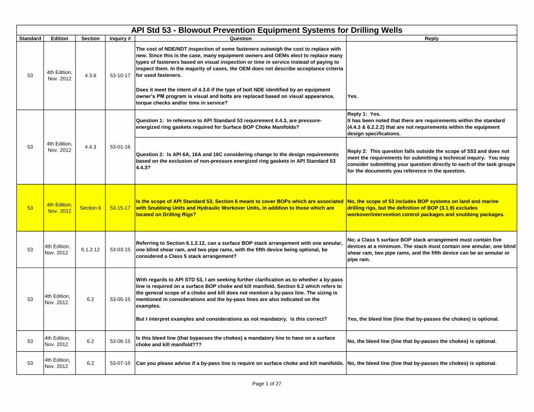
Is the scope of API Standard 53, Section 6 meant to cover BOPs which are associated
with Snubbing Units and Hydraulic Workover Units, in addition to those which are
located on Drilling Rigs?
No, the scope of 53 includes BOP systems on land and marine
drilling rigs, but the definition of BOP (3.1.9) excludes
workover/intervention control packages and snubbing packages.
534th Edition,
Nov. 20126.1.2.12 53-03-15
Referring to Section 6.1.2.12, can a surface BOP stack arrangement with one annular,
one blind shear ram, and two pipe rams, with the fifth device being optional, be
considered a Class 5 stack arrangement?
No; a Class 5 surface BOP stack arrangement must contain five
devices at a minimum. The stack must contain one annular, one blind
shear ram, two pipe rams, and the fifth device can be an annular or
pipe ram.
534th Edition,
Nov. 20126.2 53-05-15
With regards to API STD 53, I am seeking further clarification as to whether a by-pass
line is required on a surface BOP choke and kill manifold. Section 6.2 which refers to
the general scope of a choke and kill does not mention a by-pass line. The sizing is
mentioned in considerations and the by-pass lines are also indicated on the
examples.
But I interpret examples and considerations as not mandatory. Is this correct? Yes, the bleed line (line that by-passes the chokes) is optional.
534th Edition,
Nov. 20126.2 53-06-15
Is this bleed line (that bypasses the chokes) a mandatory line to have on a surface
choke and kill manifold???No, the bleed line (line that by-passes the chokes) is optional.
534th Edition,
Nov. 20126.2 53-07-15 Can you please advise if a by-pass line is require on surface choke and kill manifolds. No, the bleed line (line that by-passes the chokes) is optional.
53-10-174th Edition,
Nov. 20124.3.6
4th Edition,
Nov. 20124.4.3 53-01-16
API Std 53 - Blowout Prevention Equipment Systems for Drilling Wells
53
53
Last update: August 12, 2015
Page 1 of 27
Standard Edition Section Inquiry # Question Reply
API Std 53 - Blowout Prevention Equipment Systems for Drilling WellsLast update: August 12, 2015
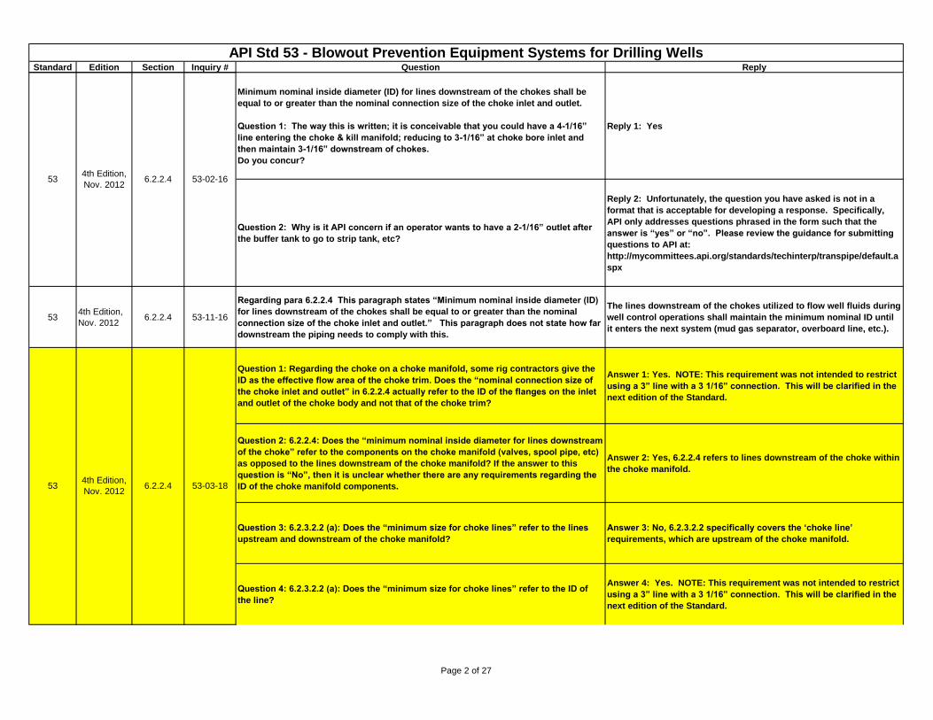
Minimum nominal inside diameter (ID) for lines downstream of the chokes shall be
equal to or greater than the nominal connection size of the choke inlet and outlet.
Question 1: The way this is written; it is conceivable that you could have a 4-1/16”
line entering the choke & kill manifold; reducing to 3-1/16” at choke bore inlet and
then maintain 3-1/16” downstream of chokes.
Do you concur?
Reply 1: Yes
Question 2: Why is it API concern if an operator wants to have a 2-1/16” outlet after
the buffer tank to go to strip tank, etc?
Reply 2: Unfortunately, the question you have asked is not in a
format that is acceptable for developing a response. Specifically,
API only addresses questions phrased in the form such that the
answer is “yes” or “no”. Please review the guidance for submitting
questions to API at:
http://mycommittees.api.org/standards/techinterp/transpipe/default.a
spx
534th Edition,
Nov. 20126.2.2.4 53-11-16
Regarding para 6.2.2.4 This paragraph states “Minimum nominal inside diameter (ID)
for lines downstream of the chokes shall be equal to or greater than the nominal
connection size of the choke inlet and outlet.” This paragraph does not state how far
downstream the piping needs to comply with this.
The lines downstream of the chokes utilized to flow well fluids during
well control operations shall maintain the minimum nominal ID until
it enters the next system (mud gas separator, overboard line, etc.).
Question 1: Regarding the choke on a choke manifold, some rig contractors give the
ID as the effective flow area of the choke trim. Does the “nominal connection size of
the choke inlet and outlet” in 6.2.2.4 actually refer to the ID of the flanges on the inlet
and outlet of the choke body and not that of the choke trim?
Answer 1: Yes. NOTE: This requirement was not intended to restrict
using a 3” line with a 3 1/16” connection. This will be clarified in the
next edition of the Standard.
Question 2: 6.2.2.4: Does the “minimum nominal inside diameter for lines downstream
of the choke” refer to the components on the choke manifold (valves, spool pipe, etc)
as opposed to the lines downstream of the choke manifold? If the answer to this
question is “No”, then it is unclear whether there are any requirements regarding the
ID of the choke manifold components.
Answer 2: Yes, 6.2.2.4 refers to lines downstream of the choke within
the choke manifold.
Question 3: 6.2.3.2.2 (a): Does the “minimum size for choke lines” refer to the lines
upstream and downstream of the choke manifold?
Answer 3: No, 6.2.3.2.2 specifically covers the ‘choke line’
requirements, which are upstream of the choke manifold.
Question 4: 6.2.3.2.2 (a): Does the “minimum size for choke lines” refer to the ID of
the line?
Answer 4: Yes. NOTE: This requirement was not intended to restrict
using a 3” line with a 3 1/16” connection. This will be clarified in the
next edition of the Standard.
534th Edition,
Nov. 20126.2.2.4 53-02-16
534th Edition,
Nov. 20126.2.2.4 53-03-18
Page 2 of 27
Standard Edition Section Inquiry # Question Reply
API Std 53 - Blowout Prevention Equipment Systems for Drilling WellsLast update: August 12, 2015
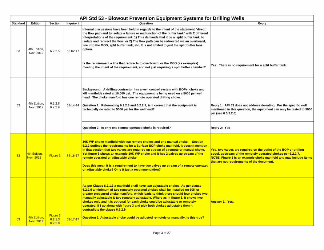
Internal discussions have been held in regards to the intent of the statement "direct
the flow path and to isolate a failure or malfunction of the buffer tank" with 2 different
interpretations of the requirement: 1) This demands that it be a 'split buffer tank' to
isolate and redirect the flow, or 2) The flow path can be redirected via an overboard,
line into the MGS, split buffer tank, etc. It is not limited to just the split buffer tank
option.
Is the requirement a line that redirects to overboard, or the MGS (as examples)
meeting the intent of the requirement, and not just requiring a split buffer chamber? Yes. There is no requirement for a split buffer tank.
Background: A drilling contractor has a well control system with BOPs, choke and
kill manifolds rated at 10,000 psi. The equipment is being used on a 5000 psi well
head. The choke manifold has one remote operated drilling choke.
Question 1: Referencing 6.2.2.8 and 6.2.2.9, is it correct that the equipment is
technically de rated to 5000 psi for the wellhead?
Reply 1: API 53 does not address de-rating. For the specific well
mentioned in this question, the equipment can only be tested to 5000
psi (see 6.5.3.2.6).
Question 2: Is only one remote operated choke is required? Reply 2: Yes
534th Edition,
Nov. 2012Figure 3 53-16-17
10K WP choke manifold with two remote chokes and one manual choke. Section
6.2.2 outlines the requirements for a Surface BOP choke manifold. It doesn't mention
in that section that two valves are required up stream of a remote or manual choke.
Yet figure 3 shows an example 10K WP choke and it has 2 valves up stream of the
remote operated or adjustable choke
Does this mean it is a requirement to have two valves up stream of a remote operated
or adjustable choke? Or is it just a recommendation?
Yes, two valves are required on the outlet of the BOP or drilling
spool, upstream of the remotely operated chokes per 6.2.2.7.
NOTE: Figure 3 is an example choke manifold and may include items
that are not requirements of the document.
As per Clause 6.2.1.3 a manifold shall have two adjustable chokes. As per clause
6.2.2.9 a minimum of two remotely operated chokes shall be installed on 10K or
greater pressured choke manifold. which leads to think there should four chokes two
manually adjustable & two remotely adjustable. Where as in figure 3, it shows two
chokes only and it is optional for each choke could be adjustable or remotely
operated. If I go along with figure 3 and pick both chokes adjustable then it
contradicts the clause 6.2.2.9.
Question 1. Adjustable choke could be adjusted remotely or manually, is this true?
Answer 1: Yes.
534th Edition,
Nov. 20126.2.2.5 53-02-17
534th Edition,
Nov. 2012
6.2.2.8
6.2.2.953-14-14
534th Edition,
Nov. 2012
Figure 3
6.2.1.3
6.2.2.9
53-17-17
Page 3 of 27
Standard Edition Section Inquiry # Question Reply
API Std 53 - Blowout Prevention Equipment Systems for Drilling WellsLast update: August 12, 2015
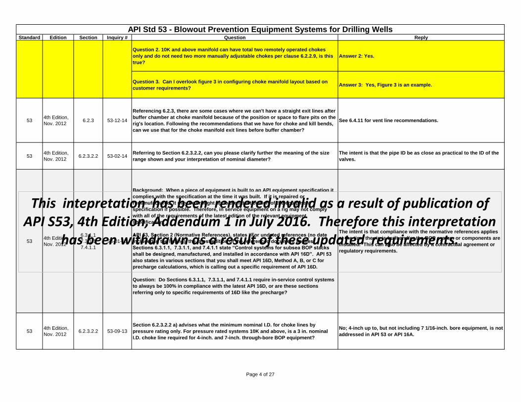
Question 2. 10K and above manifold can have total two remotely operated chokes
only and do not need two more manually adjustable chokes per clause 6.2.2.9, is this
true?
Answer 2: Yes.
Question 3. Can I overlook figure 3 in configuring choke manifold layout based on
customer requirements? Answer 3: Yes, Figure 3 is an example.
534th Edition,
Nov. 20126.2.3 53-12-14
Referencing 6.2.3, there are some cases where we can't have a straight exit lines after
buffer chamber at choke manifold because of the position or space to flare pits on the
rig's location. Following the recommendations that we have for choke and kill bends,
can we use that for the choke manifold exit lines before buffer chamber?
See 6.4.11 for vent line recommendations.
534th Edition,
Nov. 20126.2.3.2.2 53-02-14
Referring to Section 6.2.3.2.2, can you please clarify further the meaning of the size
range shown and your interpretation of nominal diameter?
The intent is that the pipe ID be as close as practical to the ID of the
valves.
534th Edition,
Nov. 2012
6.3.1.1
7.3.1.1
7.4.1.1
53-01-13
Background: When a piece of equipment is built to an API equipment specification it
complies with the specification at the time it was built. If it is repaired or
remanufactured, it may be brought up to the latest edition of the equipment
specification if possible. Therefore, in service equipment on a rig may not comply
with all of the requirements of the latest edition of the relevant equipment
specification.
API 53, Section 2 (Normative References), states “For undated references (no date
included in the listing), the latest edition of the referenced document applies”.
Sections 6.3.1.1, 7.3.1.1, and 7.4.1.1 state “Control systems for subsea BOP stacks
shall be designed, manufactured, and installed in accordance with API 16D”. API 53
also states in various sections that you shall meet API 16D, Method A, B, or C for
precharge calculations, which is calling out a specific requirement of API 16D.
Question: Do Sections 6.3.1.1, 7.3.1.1, and 7.4.1.1 require in-service control systems
to always be 100% in compliance with the latest API 16D, or are these sections
referring only to specific requirements of 16D like the precharge?
The intent is that compliance with the normative references applies
at the time the rig is built and/or the BOP system or components are
installed. This can also be affected by a contractual agreement or
regulatory requirements.
534th Edition,
Nov. 20126.2.3.2.2 53-09-13
Section 6.2.3.2.2 a) advises what the minimum nominal I.D. for choke lines by
pressure rating only. For pressure rated systems 10K and above, is a 3 in. nominal
I.D. choke line required for 4-inch. and 7-inch. through-bore BOP equipment?
No; 4-inch up to, but not including 7 1/16-inch. bore equipment, is not
addressed in API 53 or API 16A.
534th Edition,
Nov. 2012
Figure 3
6.2.1.3
6.2.2.9
53-17-17
This intepretation has been rendered invalid as a result of publication of API S53, 4th Edition, Addendum 1 in July 2016. Therefore this interpretation
has been withdrawn as a result of these updated requirements.
Page 4 of 27
Standard Edition Section Inquiry # Question Reply
API Std 53 - Blowout Prevention Equipment Systems for Drilling WellsLast update: August 12, 2015
534th Edition,
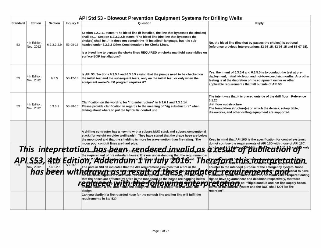
Nov. 20126.2.3.2.2.b 53-08-16
Section 7.2.2.11 states "The bleed line (if installed, the line that bypasses the chokes)
shall be..." Section 6.2.3.2.2.b states "The bleed line (the line that bypasses the
chokes) shall be...". It does not contain the "if installed" language, but it is sub-
headed under 6.2.3.2 Other Considerations for Choke Lines.
Is a bleed line to bypass the choke lines REQUIRED on choke manifold assemblies on
surface BOP installations?
No, the bleed line (line that by-passes the chokes) is optional
(reference previous interpretations 53-05-15, 53-06-15 and 53-07-15).
534th Edition,
Nov. 20126.3.5 53-12-13
Is API 53, Sections 6.3.5.4 and 6.3.5.5 saying that the pumps need to be checked on
the initial test and the subsequent tests, only on the initial test, or only when the
equipment owner’s PM program requires it?
Yes; the intent of 6.3.5.4 and 6.3.5.5 is to conduct the test at pre-
deployment, initial latch-up, and not-to-exceed six months. Any other
testing is at the discretion of the equipment owner or other
applicable requirements that fall outside of API 53.
534th Edition,
Nov. 20126.3.6.1 53-28-16
Clarification on the wording for "rig substructure" in 6.3.6.1 and 7.3.5.14.
Please provide clarification in regards to the meaning of "rig substructure" when
talking about where to put the hydraulic control unit.
The intent was that it is placed outside of the drill floor. Reference
3.1.25
drill floor substructure
The foundation structure(s) on which the derrick, rotary table,
drawworks, and other drilling equipment are supported.
534th Edition,
Nov. 2012
6.3.11.2.5
7.3.13.2.5
7.4.8.2.5
7.3.13.2.5
53-03-13
A drilling contractor has a new rig with a subsea MUX stack and subsea conventional
stack (for weight on older wellheads). They have stated that the drape hose are below
the moonpool and that the shielding is more for wave motion than fire rating. The
moon pool conduit lines are hard pipe.
Sections 6.3.11.2.5, 7.3.13.2.5, 7.4.8.2.5, and 7.3.13.2.5 are ambiguous with respect to
the requirement of fire retardant hoses. It is our understanding that the requirement in
7.3.13.2.5 takes precedence and hence the hoses should not be fire retardant.
The note in Std 53 indicates that the API requirement assumes that a fire in the
moonpool would burn out the conduit hoses and hence trigger the deadman system if
the electrical signals are also lost. For our deepwater semis however, it is not likely
that the hoses are affected by a fire in the moonpool as the hoses are hanging below
bottom box of the rig. There is no requirement in the API of how short time the hose
should sustain a fire, and hence the design will not be a proper form of weak link
design.
Can you clarify if a fire retarded hose for the conduit line and hot line will fulfil the
requirements in Std 53?
Keep in mind that API 16D is the specification for control systems;
do not confuse the requirements of API 16D with those of API 16C
(choke and kill systems). Additionally, Section 6.3.11.2.5 applies only
to surface BOP’s.
The intent in API 53 is to provide a weak link between the control
system and the BOP because the fire retardant properties would be
counter to the intended purpose of the emergency system. Since
there are many vessel designs in operation it is not practical to have
a different option for each. Sections 7.3.18 and 7.3.19 require floating
rigs to have an autoshear and deadman respectively, therefore
should be interpreted as: “Rigid conduit and hot line supply hoses
between the control system and the BOP shall NOT be fire
retardant”.
This intepretation has been rendered invalid as a result of publication of API S53, 4th Edition, Addendum 1 in July 2016. Therefore this interpretation
has been withdrawn as a result of these updated requirements and replaced with the following interpretation.
Page 5 of 27
Standard Edition Section Inquiry # Question Reply
API Std 53 - Blowout Prevention Equipment Systems for Drilling WellsLast update: August 12, 2015
534th Edition,
Nov. 2012
6.3.11.2.5
7.3.13.2.5
7.4.8.2.5
7.3.13.2.5
53-03-13
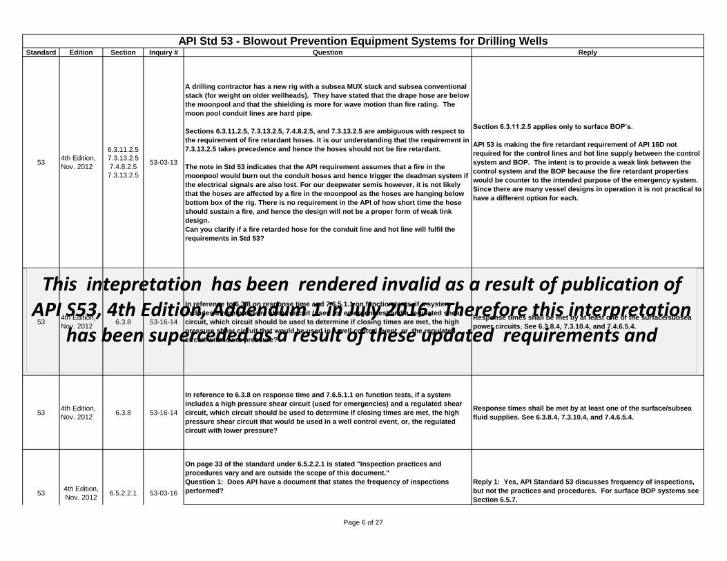
A drilling contractor has a new rig with a subsea MUX stack and subsea conventional
stack (for weight on older wellheads). They have stated that the drape hose are below
the moonpool and that the shielding is more for wave motion than fire rating. The
moon pool conduit lines are hard pipe.
Sections 6.3.11.2.5, 7.3.13.2.5, 7.4.8.2.5, and 7.3.13.2.5 are ambiguous with respect to
the requirement of fire retardant hoses. It is our understanding that the requirement in
7.3.13.2.5 takes precedence and hence the hoses should not be fire retardant.
The note in Std 53 indicates that the API requirement assumes that a fire in the
moonpool would burn out the conduit hoses and hence trigger the deadman system if
the electrical signals are also lost. For our deepwater semis however, it is not likely
that the hoses are affected by a fire in the moonpool as the hoses are hanging below
bottom box of the rig. There is no requirement in the API of how short time the hose
should sustain a fire, and hence the design will not be a proper form of weak link
design.
Can you clarify if a fire retarded hose for the conduit line and hot line will fulfil the
requirements in Std 53?
Section 6.3.11.2.5 applies only to surface BOP’s.
API 53 is making the fire retardant requirement of API 16D not
required for the control lines and hot line supply between the control
system and BOP. The intent is to provide a weak link between the
control system and the BOP because the fire retardant properties
would be counter to the intended purpose of the emergency system.
Since there are many vessel designs in operation it is not practical to
have a different option for each.
534th Edition,
Nov. 20126.3.8 53-16-14
In reference to 6.3.8 on response time and 7.6.5.1.1 on function tests, if a system
includes a high pressure shear circuit (used for emergencies) and a regulated shear
circuit, which circuit should be used to determine if closing times are met, the high
pressure shear circuit that would be used in a well control event, or, the regulated
circuit with lower pressure?
Response times shall be met by at least one of the surface/subsea
power circuits. See 6.3.8.4, 7.3.10.4, and 7.4.6.5.4.
534th Edition,
Nov. 20126.3.8 53-16-14
In reference to 6.3.8 on response time and 7.6.5.1.1 on function tests, if a system
includes a high pressure shear circuit (used for emergencies) and a regulated shear
circuit, which circuit should be used to determine if closing times are met, the high
pressure shear circuit that would be used in a well control event, or, the regulated
circuit with lower pressure?
Response times shall be met by at least one of the surface/subsea
fluid supplies. See 6.3.8.4, 7.3.10.4, and 7.4.6.5.4.
On page 33 of the standard under 6.5.2.2.1 is stated "Inspection practices and
procedures vary and are outside the scope of this document."
Question 1: Does API have a document that states the frequency of inspections
performed?
Reply 1: Yes, API Standard 53 discusses frequency of inspections,
but not the practices and procedures. For surface BOP systems see
Section 6.5.7.53
4th Edition,
Nov. 20126.5.2.2.1 53-03-16
This intepretation has been rendered invalid as a result of publication of API S53, 4th Edition, Addendum 1 in July 2016. Therefore this interpretation
has been superceded as a result of these updated requirements and
Page 6 of 27
Standard Edition Section Inquiry # Question Reply
API Std 53 - Blowout Prevention Equipment Systems for Drilling WellsLast update: August 12, 2015
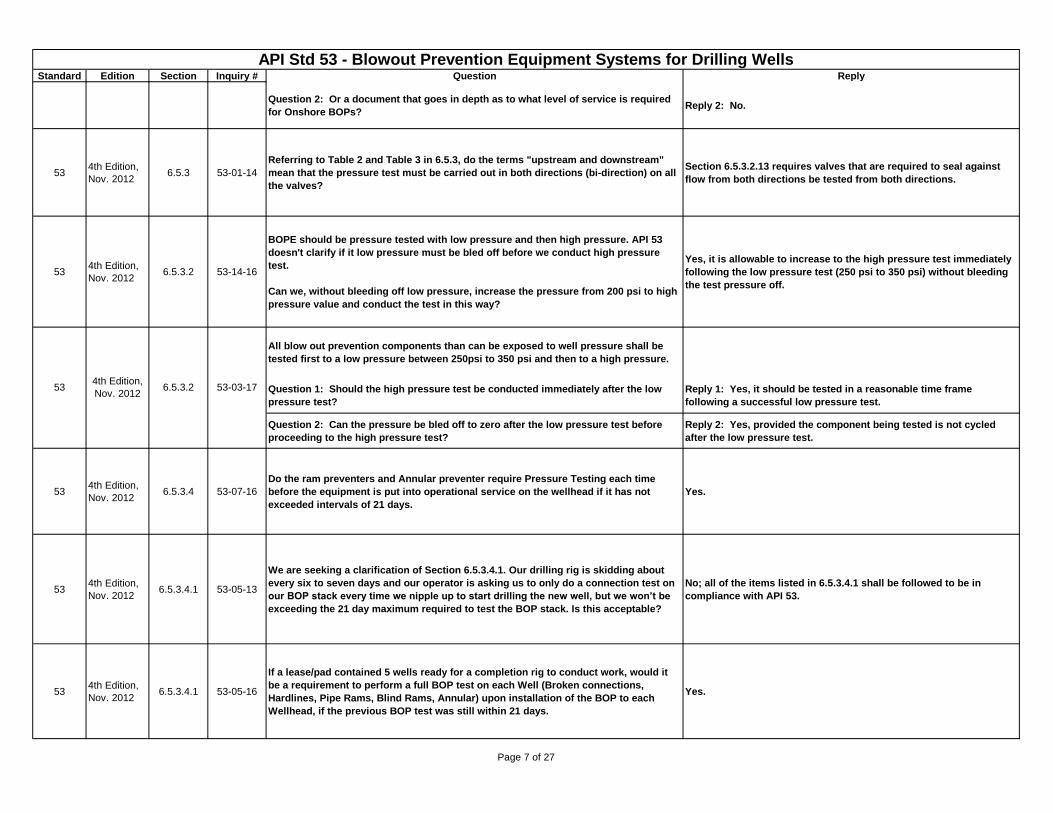
Question 2: Or a document that goes in depth as to what level of service is required
for Onshore BOPs?Reply 2: No.
534th Edition,
Nov. 20126.5.3 53-01-14
Referring to Table 2 and Table 3 in 6.5.3, do the terms "upstream and downstream"
mean that the pressure test must be carried out in both directions (bi-direction) on all
the valves?
Section 6.5.3.2.13 requires valves that are required to seal against
flow from both directions be tested from both directions.
534th Edition,
Nov. 20126.5.3.2 53-14-16
BOPE should be pressure tested with low pressure and then high pressure. API 53
doesn't clarify if it low pressure must be bled off before we conduct high pressure
test.
Can we, without bleeding off low pressure, increase the pressure from 200 psi to high
pressure value and conduct the test in this way?
Yes, it is allowable to increase to the high pressure test immediately
following the low pressure test (250 psi to 350 psi) without bleeding
the test pressure off.
All blow out prevention components than can be exposed to well pressure shall be
tested first to a low pressure between 250psi to 350 psi and then to a high pressure.
Question 1: Should the high pressure test be conducted immediately after the low
pressure test?
Reply 1: Yes, it should be tested in a reasonable time frame
following a successful low pressure test.
Question 2: Can the pressure be bled off to zero after the low pressure test before
proceeding to the high pressure test?
Reply 2: Yes, provided the component being tested is not cycled
after the low pressure test.
534th Edition,
Nov. 20126.5.3.4 53-07-16
Do the ram preventers and Annular preventer require Pressure Testing each time
before the equipment is put into operational service on the wellhead if it has not
exceeded intervals of 21 days.
Yes.
534th Edition,
Nov. 20126.5.3.4.1 53-05-13
We are seeking a clarification of Section 6.5.3.4.1. Our drilling rig is skidding about
every six to seven days and our operator is asking us to only do a connection test on
our BOP stack every time we nipple up to start drilling the new well, but we won’t be
exceeding the 21 day maximum required to test the BOP stack. Is this acceptable?
No; all of the items listed in 6.5.3.4.1 shall be followed to be in
compliance with API 53.
534th Edition,
Nov. 20126.5.3.4.1 53-05-16
If a lease/pad contained 5 wells ready for a completion rig to conduct work, would it
be a requirement to perform a full BOP test on each Well (Broken connections,
Hardlines, Pipe Rams, Blind Rams, Annular) upon installation of the BOP to each
Wellhead, if the previous BOP test was still within 21 days.
Yes.
53 53-03-174th Edition,
Nov. 20126.5.3.2
534th Edition,
Nov. 20126.5.2.2.1 53-03-16
Page 7 of 27
Standard Edition Section Inquiry # Question Reply
API Std 53 - Blowout Prevention Equipment Systems for Drilling WellsLast update: August 12, 2015
534th Edition,
Nov. 20126.5.3.4.1 53-06-16
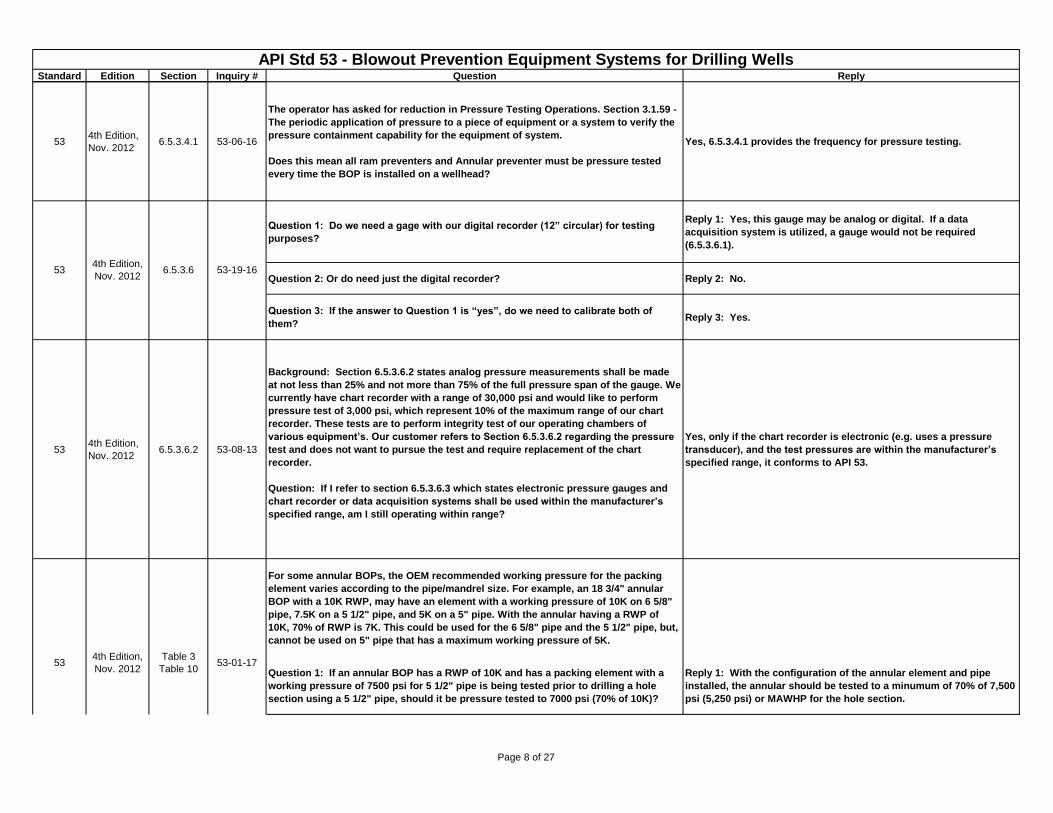
The operator has asked for reduction in Pressure Testing Operations. Section 3.1.59 -
The periodic application of pressure to a piece of equipment or a system to verify the
pressure containment capability for the equipment of system.
Does this mean all ram preventers and Annular preventer must be pressure tested
every time the BOP is installed on a wellhead?
Yes, 6.5.3.4.1 provides the frequency for pressure testing.
Question 1: Do we need a gage with our digital recorder (12” circular) for testing
purposes?
Reply 1: Yes, this gauge may be analog or digital. If a data
acquisition system is utilized, a gauge would not be required
(6.5.3.6.1).
Question 2: Or do need just the digital recorder? Reply 2: No.
Question 3: If the answer to Question 1 is “yes”, do we need to calibrate both of
them?Reply 3: Yes.
534th Edition,
Nov. 20126.5.3.6.2 53-08-13
Background: Section 6.5.3.6.2 states analog pressure measurements shall be made
at not less than 25% and not more than 75% of the full pressure span of the gauge. We
currently have chart recorder with a range of 30,000 psi and would like to perform
pressure test of 3,000 psi, which represent 10% of the maximum range of our chart
recorder. These tests are to perform integrity test of our operating chambers of
various equipment’s. Our customer refers to Section 6.5.3.6.2 regarding the pressure
test and does not want to pursue the test and require replacement of the chart
recorder.
Question: If I refer to section 6.5.3.6.3 which states electronic pressure gauges and
chart recorder or data acquisition systems shall be used within the manufacturer’s
specified range, am I still operating within range?
Yes, only if the chart recorder is electronic (e.g. uses a pressure
transducer), and the test pressures are within the manufacturer’s
specified range, it conforms to API 53.
For some annular BOPs, the OEM recommended working pressure for the packing
element varies according to the pipe/mandrel size. For example, an 18 3/4" annular
BOP with a 10K RWP, may have an element with a working pressure of 10K on 6 5/8"
pipe, 7.5K on a 5 1/2" pipe, and 5K on a 5" pipe. With the annular having a RWP of
10K, 70% of RWP is 7K. This could be used for the 6 5/8" pipe and the 5 1/2" pipe, but,
cannot be used on 5" pipe that has a maximum working pressure of 5K.
Question 1: If an annular BOP has a RWP of 10K and has a packing element with a
working pressure of 7500 psi for 5 1/2" pipe is being tested prior to drilling a hole
section using a 5 1/2" pipe, should it be pressure tested to 7000 psi (70% of 10K)?
Reply 1: With the configuration of the annular element and pipe
installed, the annular should be tested to a minumum of 70% of 7,500
psi (5,250 psi) or MAWHP for the hole section.
534th Edition,
Nov. 2012
Table 3
Table 1053-01-17
534th Edition,
Nov. 20126.5.3.6 53-19-16
Page 8 of 27
Standard Edition Section Inquiry # Question Reply
API Std 53 - Blowout Prevention Equipment Systems for Drilling WellsLast update: August 12, 2015
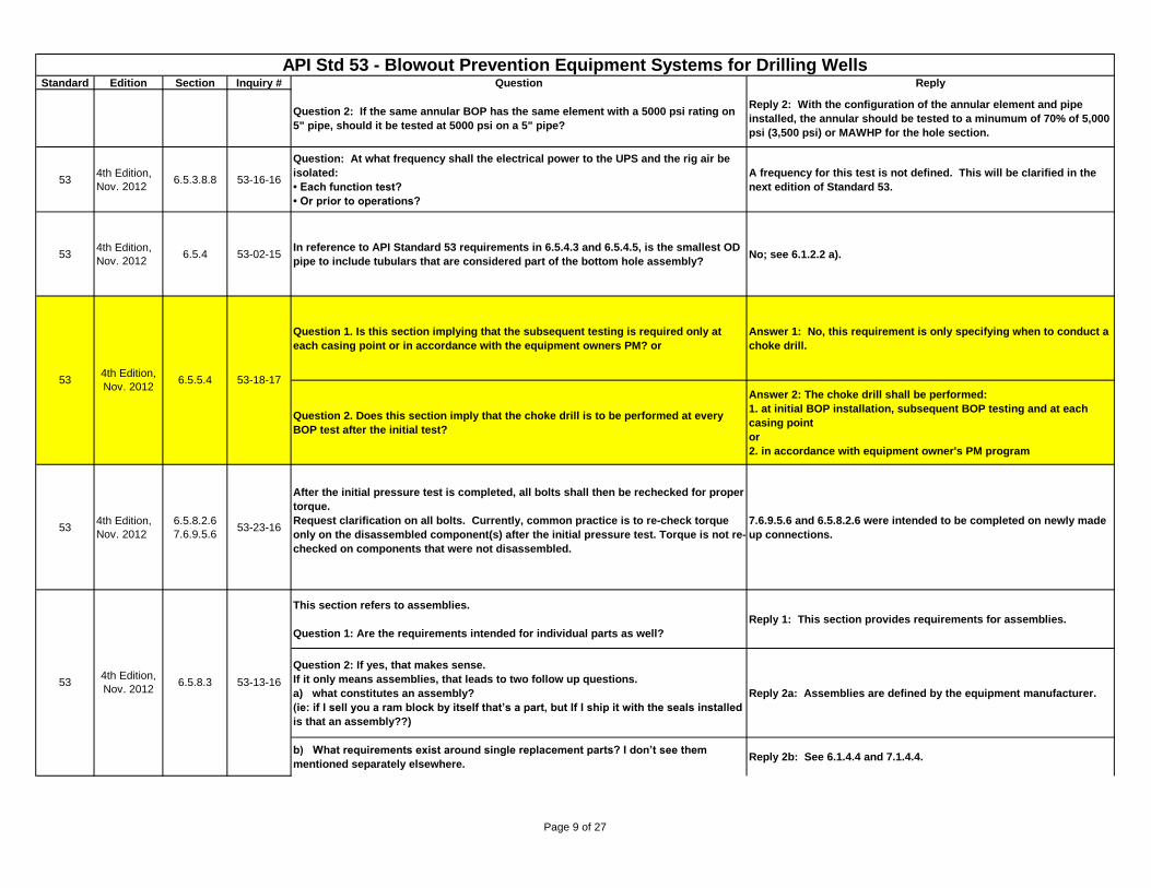
Question 2: If the same annular BOP has the same element with a 5000 psi rating on
5" pipe, should it be tested at 5000 psi on a 5" pipe?
Reply 2: With the configuration of the annular element and pipe
installed, the annular should be tested to a minumum of 70% of 5,000
psi (3,500 psi) or MAWHP for the hole section.
534th Edition,
Nov. 20126.5.3.8.8 53-16-16
Question: At what frequency shall the electrical power to the UPS and the rig air be
isolated:
• Each function test?
• Or prior to operations?
A frequency for this test is not defined. This will be clarified in the
next edition of Standard 53.
534th Edition,
Nov. 20126.5.4 53-02-15
In reference to API Standard 53 requirements in 6.5.4.3 and 6.5.4.5, is the smallest OD
pipe to include tubulars that are considered part of the bottom hole assembly?No; see 6.1.2.2 a).
Question 1. Is this section implying that the subsequent testing is required only at
each casing point or in accordance with the equipment owners PM? or
Answer 1: No, this requirement is only specifying when to conduct a
choke drill.
Question 2. Does this section imply that the choke drill is to be performed at every
BOP test after the initial test?
Answer 2: The choke drill shall be performed:
1. at initial BOP installation, subsequent BOP testing and at each
casing point
or
2. in accordance with equipment owner's PM program
534th Edition,
Nov. 2012
6.5.8.2.6
7.6.9.5.653-23-16
After the initial pressure test is completed, all bolts shall then be rechecked for proper
torque.
Request clarification on all bolts. Currently, common practice is to re-check torque
only on the disassembled component(s) after the initial pressure test. Torque is not re-
checked on components that were not disassembled.
7.6.9.5.6 and 6.5.8.2.6 were intended to be completed on newly made
up connections.
This section refers to assemblies.
Question 1: Are the requirements intended for individual parts as well?
Reply 1: This section provides requirements for assemblies.
Question 2: If yes, that makes sense.
If it only means assemblies, that leads to two follow up questions.
a) what constitutes an assembly?
(ie: if I sell you a ram block by itself that’s a part, but If I ship it with the seals installed
is that an assembly??)
Reply 2a: Assemblies are defined by the equipment manufacturer.
b) What requirements exist around single replacement parts? I don’t see them
mentioned separately elsewhere. Reply 2b: See 6.1.4.4 and 7.1.4.4.
534th Edition,
Nov. 2012
Table 3
Table 1053-01-17
534th Edition,
Nov. 20126.5.8.3 53-13-16
534th Edition,
Nov. 20126.5.5.4 53-18-17
Page 9 of 27
Standard Edition Section Inquiry # Question Reply
API Std 53 - Blowout Prevention Equipment Systems for Drilling WellsLast update: August 12, 2015
534th Edition,
Nov. 20127.1.4.4 53-13-17
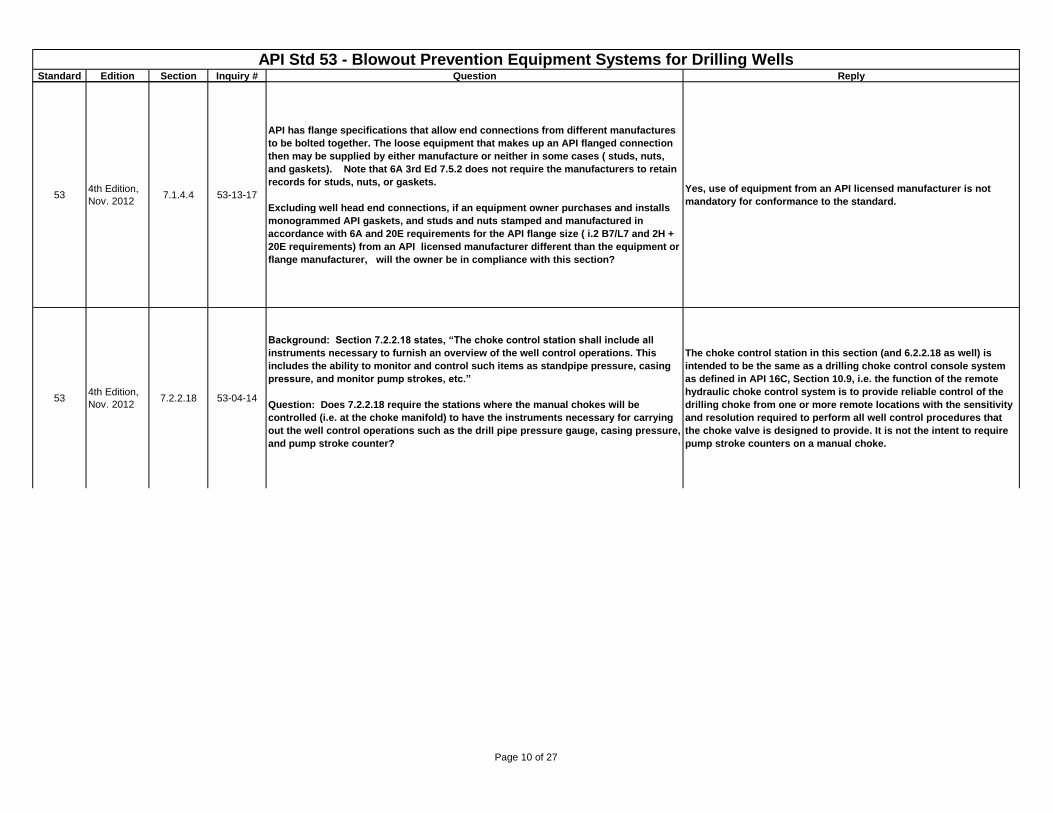
API has flange specifications that allow end connections from different manufactures
to be bolted together. The loose equipment that makes up an API flanged connection
then may be supplied by either manufacture or neither in some cases ( studs, nuts,
and gaskets). Note that 6A 3rd Ed 7.5.2 does not require the manufacturers to retain
records for studs, nuts, or gaskets.
Excluding well head end connections, if an equipment owner purchases and installs
monogrammed API gaskets, and studs and nuts stamped and manufactured in
accordance with 6A and 20E requirements for the API flange size ( i.2 B7/L7 and 2H +
20E requirements) from an API licensed manufacturer different than the equipment or
flange manufacturer, will the owner be in compliance with this section?
Yes, use of equipment from an API licensed manufacturer is not
mandatory for conformance to the standard.
534th Edition,
Nov. 20127.2.2.18 53-04-14
Background: Section 7.2.2.18 states, “The choke control station shall include all
instruments necessary to furnish an overview of the well control operations. This
includes the ability to monitor and control such items as standpipe pressure, casing
pressure, and monitor pump strokes, etc.”
Question: Does 7.2.2.18 require the stations where the manual chokes will be
controlled (i.e. at the choke manifold) to have the instruments necessary for carrying
out the well control operations such as the drill pipe pressure gauge, casing pressure,
and pump stroke counter?
The choke control station in this section (and 6.2.2.18 as well) is
intended to be the same as a drilling choke control console system
as defined in API 16C, Section 10.9, i.e. the function of the remote
hydraulic choke control system is to provide reliable control of the
drilling choke from one or more remote locations with the sensitivity
and resolution required to perform all well control procedures that
the choke valve is designed to provide. It is not the intent to require
pump stroke counters on a manual choke.
Page 10 of 27
Standard Edition Section Inquiry # Question Reply
API Std 53 - Blowout Prevention Equipment Systems for Drilling WellsLast update: August 12, 2015
534th Edition,
Nov. 20127.2.3.1.1 53-11-13
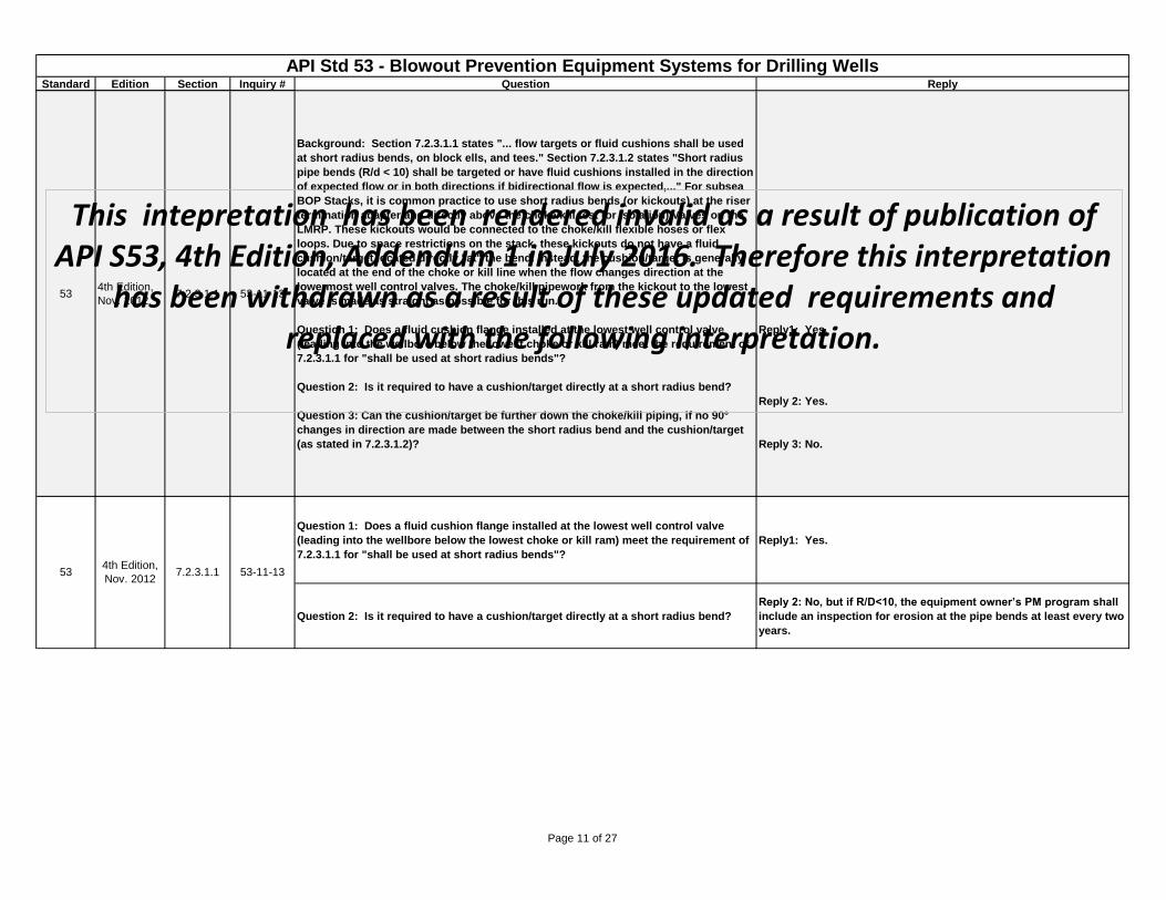
Background: Section 7.2.3.1.1 states "... flow targets or fluid cushions shall be used
at short radius bends, on block ells, and tees." Section 7.2.3.1.2 states "Short radius
pipe bends (R/d < 10) shall be targeted or have fluid cushions installed in the direction
of expected flow or in both directions if bidirectional flow is expected,..." For subsea
BOP Stacks, it is common practice to use short radius bends (or kickouts) at the riser
termination adapter and directly above the choke/kill test (or Isolation) Valves on the
LMRP. These kickouts would be connected to the choke/kill flexible hoses or flex
loops. Due to space restrictions on the stack, these kickouts do not have a fluid
cushion/target located directly "at" the bend. Instead, the cushion/target is generally
located at the end of the choke or kill line when the flow changes direction at the
lowermost well control valves. The choke/kill pipework from the kickout to the lowest
valve is made as straight as possible for this run.
Question 1: Does a fluid cushion flange installed at the lowest well control valve
(leading into the wellbore below the lowest choke or kill ram) meet the requirement of
7.2.3.1.1 for "shall be used at short radius bends"?
Question 2: Is it required to have a cushion/target directly at a short radius bend?
Question 3: Can the cushion/target be further down the choke/kill piping, if no 90°
changes in direction are made between the short radius bend and the cushion/target
(as stated in 7.2.3.1.2)?
Reply1: Yes.
Reply 2: Yes.
Reply 3: No.
Question 1: Does a fluid cushion flange installed at the lowest well control valve
(leading into the wellbore below the lowest choke or kill ram) meet the requirement of
7.2.3.1.1 for "shall be used at short radius bends"?
Reply1: Yes.
Question 2: Is it required to have a cushion/target directly at a short radius bend?
Reply 2: No, but if R/D<10, the equipment owner’s PM program shall
include an inspection for erosion at the pipe bends at least every two
years.
534th Edition,
Nov. 20127.2.3.1.1 53-11-13
This intepretation has been rendered invalid as a result of publication of API S53, 4th Edition, Addendum 1 in July 2016. Therefore this interpretation
has been withdrawn as a result of these updated requirements and replaced with the following interpretation.
Page 11 of 27
Standard Edition Section Inquiry # Question Reply
API Std 53 - Blowout Prevention Equipment Systems for Drilling WellsLast update: August 12, 2015
534th Edition,
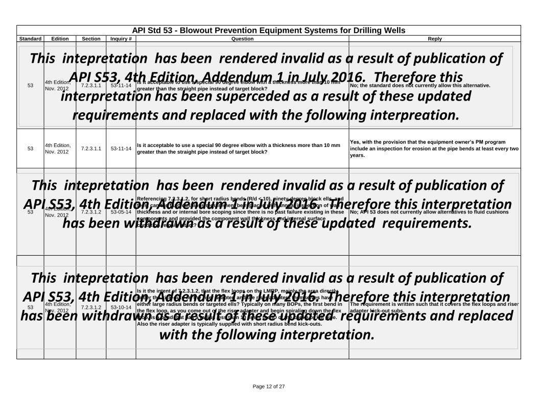
Nov. 20127.2.3.1.1 53-11-14
Is it acceptable to use a special 90 degree elbow with a thickness more than 10 mm
greater than the straight pipe instead of target block? No; the standard does not currently allow this alternative.
534th Edition,
Nov. 20127.2.3.1.1 53-11-14
Is it acceptable to use a special 90 degree elbow with a thickness more than 10 mm
greater than the straight pipe instead of target block?
Yes, with the provision that the equipment owner’s PM program
include an inspection for erosion at the pipe bends at least every two
years.
534th Edition,
Nov. 20127.2.3.1.2 53-05-14
Referencing 7.2.3.1.2, for short radius bends (R/d < 10), ninety-degree block ells, and
tees, can the fluid cushions requirement be replaced with annual inspection of wall
thickness and or internal bore scoping since there is no past failure existing in these
components and provided the component wall thickness and internal surface
condition remain intact?
No; API 53 does not currently allow alternatives to fluid cushions
534th Edition,
Nov. 20127.2.3.1.2 53-10-14
Is it the intent of 7.2.3.1.2, that the flex loops on the LMRP, mainly the area directly
under the kick-outs on the riser adapter, and the riser adapters themselves have
either large radius bends or targeted ells? Typically on many BOPs, the first bend in
the flex loop, as you come out of the riser adapter and begin spiraling down the flex
loop, is a bend that has a radius less than 10 times the ID of the choke or kill pipe.
Also the riser adapter is typically supplied with short radius bend kick-outs.
The requirement is written such that it covers the flex loops and riser
adapter kick-out subs.
This intepretation has been rendered invalid as a result of publication of API S53, 4th Edition, Addendum 1 in July 2016. Therefore this
interpretation has been superceded as a result of these updated requirements and replaced with the following interpreation.
This intepretation has been rendered invalid as a result of publication of API S53, 4th Edition, Addendum 1 in July 2016. Therefore this interpretation
has been withdrawn as a result of these updated requirements.
This intepretation has been rendered invalid as a result of publication of API S53, 4th Edition, Addendum 1 in July 2016. Therefore this interpretation has been withdrawn as a result of these updated requirements and replaced
with the following interpretation.
Page 12 of 27
Standard Edition Section Inquiry # Question Reply
API Std 53 - Blowout Prevention Equipment Systems for Drilling WellsLast update: August 12, 2015
534th Edition,
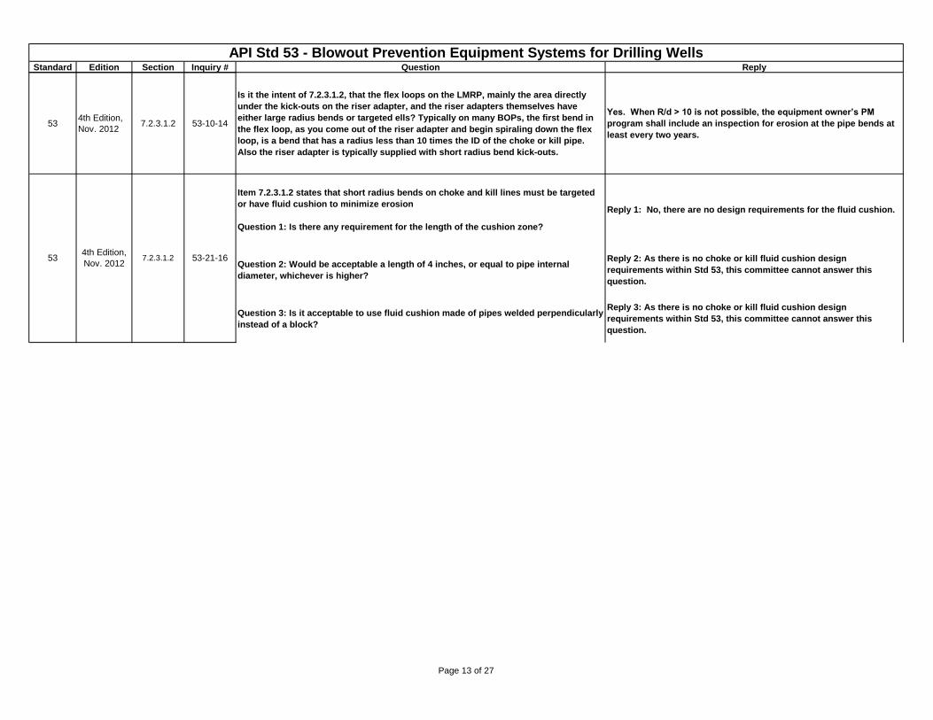
Nov. 20127.2.3.1.2 53-10-14
Is it the intent of 7.2.3.1.2, that the flex loops on the LMRP, mainly the area directly
under the kick-outs on the riser adapter, and the riser adapters themselves have
either large radius bends or targeted ells? Typically on many BOPs, the first bend in
the flex loop, as you come out of the riser adapter and begin spiraling down the flex
loop, is a bend that has a radius less than 10 times the ID of the choke or kill pipe.
Also the riser adapter is typically supplied with short radius bend kick-outs.
Yes. When R/d > 10 is not possible, the equipment owner’s PM
program shall include an inspection for erosion at the pipe bends at
least every two years.
Item 7.2.3.1.2 states that short radius bends on choke and kill lines must be targeted
or have fluid cushion to minimize erosion
Question 1: Is there any requirement for the length of the cushion zone?
Reply 1: No, there are no design requirements for the fluid cushion.
Question 2: Would be acceptable a length of 4 inches, or equal to pipe internal
diameter, whichever is higher?
Reply 2: As there is no choke or kill fluid cushion design
requirements within Std 53, this committee cannot answer this
question.
Question 3: Is it acceptable to use fluid cushion made of pipes welded perpendicularly
instead of a block?
Reply 3: As there is no choke or kill fluid cushion design
requirements within Std 53, this committee cannot answer this
question.
534th Edition,
Nov. 20127.2.3.1.2 53-21-16
Page 13 of 27
Standard Edition Section Inquiry # Question Reply
API Std 53 - Blowout Prevention Equipment Systems for Drilling WellsLast update: August 12, 2015
534th Edition,
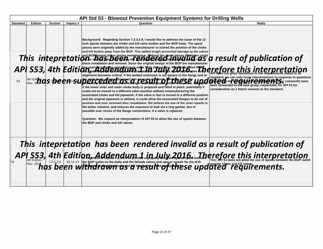
Nov. 20127.2.3.2.9 53-10-13
Background: Regarding Section 7.2.3.2.9, I would like to address the issue of the 12
inch spools between the choke and kill valve bodies and the BOP body. The spool
pieces were originally added by the manufacturer to extend the position of the choke
and kill bodies away from the BOP. This added length prevented damage to the valves
and BOP bonnet doors during maintenance. Without the spool pieces the doors could
not be opened fully, thus adding the potential to damage the door face during ram
block installation and removal. Since the original design of the BOP the manufacturer
has manufactured an extended neck valve body design. But, it must be noted there
are problems with this design. With the addition of a welded spool to the valve body
alignment becomes critical. If the welded extension is not square to the flange and to
the valve body, proper alignment can never be achieved. This also adds the
probability that the valves are no longer interchangeable within the system. Example;
if the lower inner and outer choke body is prepared and fitted in place; potentially it
could not be moved to a different valve position without remanufacturing the
associated choke and kill pipework. If the valve in fact is moved to a different position
and the original pipework is utilized, it could allow the associated flanges to be out of
position and over stressed after installation. We believe the use of the short spools is
the better solution, and reduces the exposure to leak via a ring gasket, due to
possible over stress of the flange connections, if a valve is replaced.
Question: We request an interpretation of API 53 to allow the use of spools between
the BOP and choke and kill valves.
API does not grant deviations to the requirements stated in its
standard; we can only issue interpretations in response to questions
concerning the meaning of the requirements. Your comments have
been forwarded to the task group responsible for API 53 for
consideration as a future revision to the standard.
534th Edition,
Nov. 20127.2.3.2.9 53-14-13
Is the intent of Clause 7.2.3.2.9 to prohibit a properly designed spacer spool between
the BOP outlet on the body and the failsafe valves and spacer spools for the drill-
through and all of the choke and kill lines on the stack are spools)?
Yes; API 53 does not allow for use of spools between the BOP outlet
and the choke and kill valves.
This intepretation has been rendered invalid as a result of publication of API S53, 4th Edition, Addendum 1 in July 2016. Therefore this interpretation
has been superceded as a result of these updated requirements.
This intepretation has been rendered invalid as a result of publication of API S53, 4th Edition, Addendum 1 in July 2016. Therefore this interpretation
has been withdrawn as a result of these updated requirements.
This intepretation has been rendered invalid as a result of publication of
Page 14 of 27
Standard Edition Section Inquiry # Question Reply
API Std 53 - Blowout Prevention Equipment Systems for Drilling WellsLast update: August 12, 2015
534th Edition,
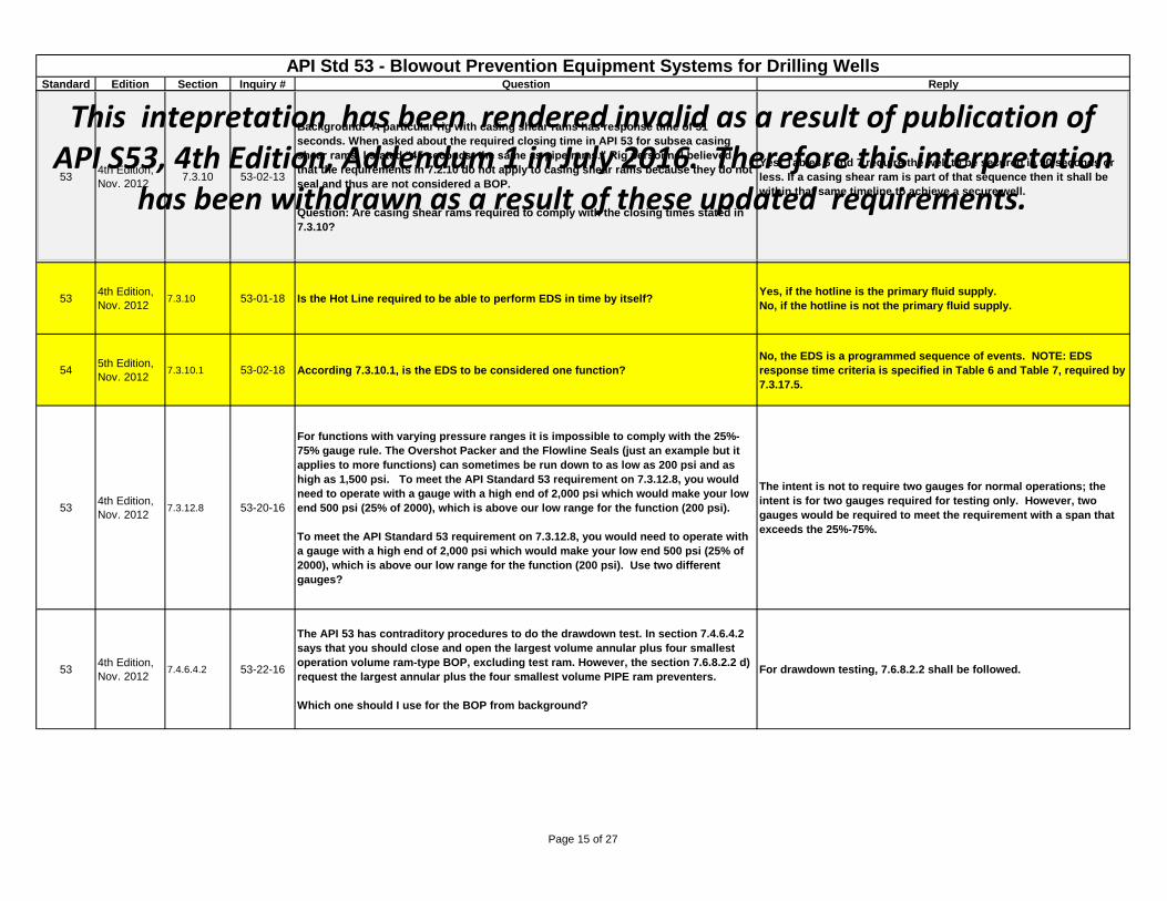
Nov. 20127.3.10 53-02-13
Background: A particular rig with casing shear rams has response time of 51
seconds. When asked about the required closing time in API 53 for subsea casing
shear rams, I stated “45 seconds, the same as pipe rams.” Rig personnel believed
that the requirements in 7.2.10 do not apply to casing shear rams because they do not
seal and thus are not considered a BOP.
Question: Are casing shear rams required to comply with the closing times stated in
7.3.10?
Yes; Tables 6 and 7 require the well to be secured in 90 seconds or
less. If a casing shear ram is part of that sequence then it shall be
within that same timeline to achieve a secure well.
534th Edition,
Nov. 20127.3.10 53-01-18 Is the Hot Line required to be able to perform EDS in time by itself?
Yes, if the hotline is the primary fluid supply.
No, if the hotline is not the primary fluid supply.
545th Edition,
Nov. 20127.3.10.1 53-02-18 According 7.3.10.1, is the EDS to be considered one function?
No, the EDS is a programmed sequence of events. NOTE: EDS
response time criteria is specified in Table 6 and Table 7, required by
7.3.17.5.
534th Edition,
Nov. 20127.3.12.8 53-20-16
For functions with varying pressure ranges it is impossible to comply with the 25%-
75% gauge rule. The Overshot Packer and the Flowline Seals (just an example but it
applies to more functions) can sometimes be run down to as low as 200 psi and as
high as 1,500 psi. To meet the API Standard 53 requirement on 7.3.12.8, you would
need to operate with a gauge with a high end of 2,000 psi which would make your low
end 500 psi (25% of 2000), which is above our low range for the function (200 psi).
To meet the API Standard 53 requirement on 7.3.12.8, you would need to operate with
a gauge with a high end of 2,000 psi which would make your low end 500 psi (25% of
2000), which is above our low range for the function (200 psi). Use two different
gauges?
The intent is not to require two gauges for normal operations; the
intent is for two gauges required for testing only. However, two
gauges would be required to meet the requirement with a span that
exceeds the 25%-75%.
534th Edition,
Nov. 20127.4.6.4.2 53-22-16
The API 53 has contraditory procedures to do the drawdown test. In section 7.4.6.4.2
says that you should close and open the largest volume annular plus four smallest
operation volume ram-type BOP, excluding test ram. However, the section 7.6.8.2.2 d)
request the largest annular plus the four smallest volume PIPE ram preventers.
Which one should I use for the BOP from background?
For drawdown testing, 7.6.8.2.2 shall be followed.
This intepretation has been rendered invalid as a result of publication of API S53, 4th Edition, Addendum 1 in July 2016. Therefore this interpretation
has been withdrawn as a result of these updated requirements.
Page 15 of 27
Standard Edition Section Inquiry # Question Reply
API Std 53 - Blowout Prevention Equipment Systems for Drilling WellsLast update: August 12, 2015
534th Edition,
Nov. 20127.4.6.6.3 53-26-16
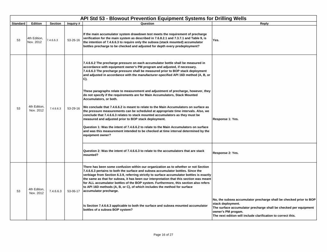
If the main accumulator system drawdown test meets the requirement of precharge
verification for the main system as described in 7.6.8.2.1 and 7.3.7.1 and Table 9, is
the intention of 7.4.6.6.3 to require only the subsea (stack mounted) accumulator
bottles precharge to be checked and adjusted for depth every predeployment?
Yes.
7.4.6.6.2 The precharge pressure on each accumulator bottle shall be measured in
accordance with equipment owner's PM program and adjusted, if necessary.
7.4.6.6.3 The precharge pressure shall be measured prior to BOP stack deployment
and adjusted in accordance with the manufacturer-specified API 16D method (A, B, or
C).
These paragraphs relate to measurement and adjustment of precharge, however, they
do not specify if the requirements are for Main Accumulators, Stack Mounted
Accumulators, or both.
We conclude that 7.4.6.6.2 is meant to relate to the Main Accumulators on surface as
the pressure measurements can be scheduled at appropriate time intervals. Also, we
conclude that 7.4.6.6.3 relates to stack mounted accumulators as they must be
measured and adjusted prior to BOP stack deployment.
Question 1: Was the intent of 7.4.6.6.2 to relate to the Main Accumulators on surface
and was this measurement intended to be checked at time interval determined by the
equipment owner?
Response 1: Yes.
Question 2: Was the intent of 7.4.6.6.3 to relate to the accumulators that are stack
mounted?Response 2: Yes.
There has been some confusion within our organization as to whether or not Section
7.4.6.6.3 pertains to both the surface and subsea accumulator bottles. Since the
verbiage from Section 6.3.9, referring strictly to surface accumulator bottles is exactly
the same as that for subsea, it has been our interpretation that this section was meant
for ALL accumulator bottles of the BOP system. Furthermore, this section also refers
to API 16D methods (A, B, or C), of which includes the method for surface
accumulator precharge.
Is Section 7.4.6.6.3 applicable to both the surface and subsea mounted accumulator
bottles of a subsea BOP system?
No, the subsea accumulator precharge shall be checked prior to BOP
stack deployment.
The surface accumulator precharge shall be checked per equipment
owner's PM progam.
The next edition will include clarification to correct this.
534th Edition,
Nov. 20127.4.6.6.3 53-06-17
534th Edition,
Nov. 20127.4.6.6.3 53-29-16
Page 16 of 27
Standard Edition Section Inquiry # Question Reply
API Std 53 - Blowout Prevention Equipment Systems for Drilling WellsLast update: August 12, 2015
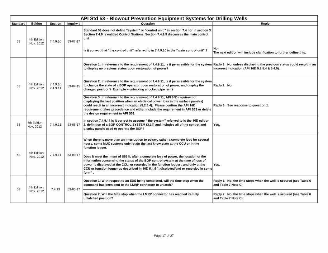
Standard 53 does not define "system" or "control unit " in section 7.4 nor in section 3.
Section 7.4.9 is entitled Control Stations. Section 7.4.9.9 discusses the main control
unit
Is it correct that "the control unit" referred to in 7.4.9.10 is the "main control unit" ? No.
The next edition will include clarification to further define this.
Question 1: In reference to the requirement of 7.4.9.11, is it permissible for the system
to display no previous status upon restoration of power?
Reply 1: No, unless displaying the previous status could result in an
incorrect indication (API 16D 5.2.5.4 & 5.4.5).
Question 2: In reference to the requirement of 7.4.9.11, is it permissible for the system
to change the state of a BOP operator upon restoration of power, and display the
changed position? Example – unlocking a locked pipe ram?
Reply 2: No.
Question 3: In reference to the requirement of 7.4.9.11, API 16D requires not
displaying the last position when an electrical power loss in the surface panel(s)
could result in an incorrect indication (5.2.5.4). Please confirm the API 16D
requirement takes precedence and either include the requirement in API S53 or delete
the design requirement in API S53.
Reply 3: See response to question 1.
534th Edition,
Nov. 20127.4.9.11 53-08-17
In section 7.4.9.11 is it correct to assume “ the system” referred to is the 16D edition
2, definition of a BOP CONTROL SYSTEM (3.14) and includes all of the control and
display panels used to operate the BOP?
Yes.
When there is more than an interruption to power, rather a complete loss for several
hours, some MUX systems only retain the last know state at the CCU or in the
function logger.
Does it meet the intent of S53 if, after a complete loss of power, the location of the
information concerning the status of the BOP control system at the time of loss of
power is displayed at the CCU, or recorded in the function logger , and only at the
CCU or function logger as described in 16D 5.4.5 “..displayed/and or recorded in some
form” .
Yes.
Question 1: With respect to an EDS being completed, will the time stop when the
command has been sent to the LMRP connector to unlatch?
Reply 1: No, the time stops when the well is secured (see Table 6
and Table 7 Note C).
Question 2: Will the time stop when the LMRP connector has reached its fully
unlatched position?
Reply 2: No, the time stops when the well is secured (see Table 6
and Table 7 Note C).
534th Edition,
Nov. 20127.4.9.10 53-07-17
53-09-17534th Edition,
Nov. 2012
534th Edition,
Nov. 20127.4.13 53-05-17
7.4.9.11
534th Edition,
Nov. 2012
7.4.9.10
7.4.9.1153-04-15
Page 17 of 27
Standard Edition Section Inquiry # Question Reply
API Std 53 - Blowout Prevention Equipment Systems for Drilling WellsLast update: August 12, 2015
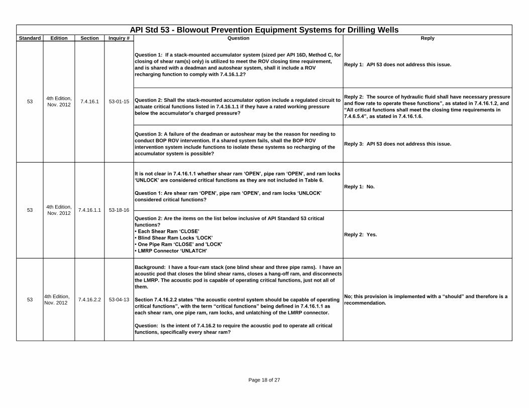
Question 1: If a stack-mounted accumulator system (sized per API 16D, Method C, for
closing of shear ram(s) only) is utilized to meet the ROV closing time requirement,
and is shared with a deadman and autoshear system, shall it include a ROV
recharging function to comply with 7.4.16.1.2?
Reply 1: API 53 does not address this issue.
Question 2: Shall the stack-mounted accumulator option include a regulated circuit to
actuate critical functions listed in 7.4.16.1.1 if they have a rated working pressure
below the accumulator’s charged pressure?
Reply 2: The source of hydraulic fluid shall have necessary pressure
and flow rate to operate these functions”, as stated in 7.4.16.1.2, and
“All critical functions shall meet the closing time requirements in
7.4.6.5.4”, as stated in 7.4.16.1.6.
Question 3: A failure of the deadman or autoshear may be the reason for needing to
conduct BOP ROV intervention. If a shared system fails, shall the BOP ROV
intervention system include functions to isolate these systems so recharging of the
accumulator system is possible?
Reply 3: API 53 does not address this issue.
It is not clear in 7.4.16.1.1 whether shear ram ‘OPEN’, pipe ram ‘OPEN’, and ram locks
‘UNLOCK’ are considered critical functions as they are not included in Table 6.
Question 1: Are shear ram ‘OPEN’, pipe ram ‘OPEN’, and ram locks ‘UNLOCK’
considered critical functions?
Reply 1: No.
Question 2: Are the items on the list below inclusive of API Standard 53 critical
functions?
• Each Shear Ram ‘CLOSE’
• Blind Shear Ram Locks ‘LOCK’
• One Pipe Ram ‘CLOSE’ and 'LOCK'
• LMRP Connector ‘UNLATCH’
Reply 2: Yes.
534th Edition,
Nov. 20127.4.16.2.2 53-04-13
Background: I have a four-ram stack (one blind shear and three pipe rams). I have an
acoustic pod that closes the blind shear rams, closes a hang-off ram, and disconnects
the LMRP. The acoustic pod is capable of operating critical functions, just not all of
them.
Section 7.4.16.2.2 states “the acoustic control system should be capable of operating
critical functions”, with the term “critical functions” being defined in 7.4.16.1.1 as
each shear ram, one pipe ram, ram locks, and unlatching of the LMRP connector.
Question: Is the intent of 7.4.16.2 to require the acoustic pod to operate all critical
functions, specifically every shear ram?
No; this provision is implemented with a “should” and therefore is a
recommendation.
534th Edition,
Nov. 20127.4.16.1 53-01-15
534th Edition,
Nov. 20127.4.16.1.1 53-18-16
Page 18 of 27
Standard Edition Section Inquiry # Question Reply
API Std 53 - Blowout Prevention Equipment Systems for Drilling WellsLast update: August 12, 2015
534th Edition,
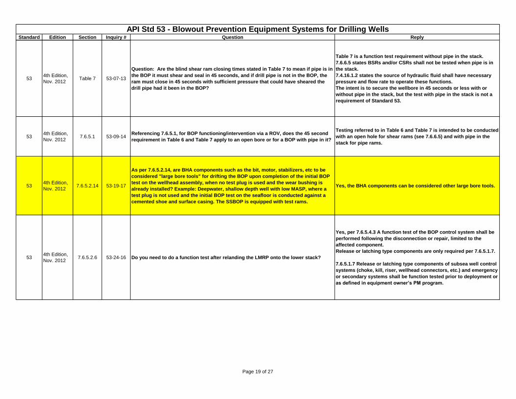
Nov. 2012Table 7 53-07-13
Question: Are the blind shear ram closing times stated in Table 7 to mean if pipe is in
the BOP it must shear and seal in 45 seconds, and if drill pipe is not in the BOP, the
ram must close in 45 seconds with sufficient pressure that could have sheared the
drill pipe had it been in the BOP?
Table 7 is a function test requirement without pipe in the stack.
7.6.6.5 states BSRs and/or CSRs shall not be tested when pipe is in
the stack.
7.4.16.1.2 states the source of hydraulic fluid shall have necessary
pressure and flow rate to operate these functions.
The intent is to secure the wellbore in 45 seconds or less with or
without pipe in the stack, but the test with pipe in the stack is not a
requirement of Standard 53.
534th Edition,
Nov. 20127.6.5.1 53-09-14
Referencing 7.6.5.1, for BOP functioning/intervention via a ROV, does the 45 second
requirement in Table 6 and Table 7 apply to an open bore or for a BOP with pipe in it?
Testing referred to in Table 6 and Table 7 is intended to be conducted
with an open hole for shear rams (see 7.6.6.5) and with pipe in the
stack for pipe rams.
534th Edition,
Nov. 20127.6.5.2.14 53-19-17
As per 7.6.5.2.14, are BHA components such as the bit, motor, stabilizers, etc to be
considered "large bore tools" for drifting the BOP upon completion of the initial BOP
test on the wellhead assembly, when no test plug is used and the wear bushing is
already installed? Example: Deepwater, shallow depth well with low MASP, where a
test plug is not used and the initial BOP test on the seafloor is conducted against a
cemented shoe and surface casing. The SSBOP is equipped with test rams.
Yes, the BHA components can be considered other large bore tools.
534th Edition,
Nov. 20127.6.5.2.6 53-24-16 Do you need to do a function test after relanding the LMRP onto the lower stack?
Yes, per 7.6.5.4.3 A function test of the BOP control system shall be
performed following the disconnection or repair, limited to the
affected component.
Release or latching type components are only required per 7.6.5.1.7.
7.6.5.1.7 Release or latching type components of subsea well control
systems (choke, kill, riser, wellhead connectors, etc.) and emergency
or secondary systems shall be function tested prior to deployment or
as defined in equipment owner’s PM program.
Page 19 of 27
Standard Edition Section Inquiry # Question Reply
API Std 53 - Blowout Prevention Equipment Systems for Drilling WellsLast update: August 12, 2015
534th Edition,
Nov. 2012
7.6.5.2.6
Table 1053-25-16
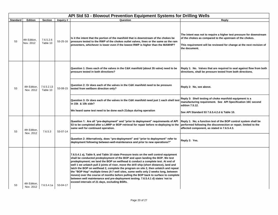
Is it the intent that the portion of the manifold that is downstream of the chokes be
pressure tested to the RWP of the chokes outlet valves, lines or the same as the ram
preventers, whichever is lower even if the lowest RWP is higher than the MAWHP?
The intent was not to require a higher test pressure for downstream
of the chokes as compared to the upstream of the chokes.
This requirement will be reviewed for change at the next revision of
the document.
Question 1: Does each of the valves in the C&K manifold (about 35 valve) need to be
pressure tested in both directions?
Reply 1: No. Valves that are required to seal against flow from both
directions, shall be pressure tested from both directions.
Question 2: Or does each of the valves in the C&K manifold need to be pressure
tested from wellbore direction only? Reply 2: No, see above.
Question 3: Or does each of the valves in the C&K manifold need just 1 each shell test
in 15k & 10k side?
We heard same test need to be done each 21days during operation
Reply 3: Shell testing of choke manifold equipment is a
manufacturing requirement. See API Specification 16C second
edition 7.5.12.
See API Standard 53 7.6.5.4.2.d & Table 10.
Question 1: Are all “pre-deployment” and “prior to deployment” requirements of API
53 to be completed after a LMRP or BOP retrieval for repair before re-deploying to the
same well for continued operation.
Reply 1: No; a function test of the BOP control system shall be
performed following the disconnection or repair, limited to the
affected component, as stated in 7.6.5.4.3.
Question 2: Alternatively, does “pre-deployment” and “prior to deployment” refer to
deployment following between-well-maintenance and prior to new operations?”Reply 2: Yes.
7.6.5.4.1 a), Table 9, and Table 10 state Pressure tests on the well control equipment
shall be conducted predeployment of the BOP and upon landing the BOP. We test
predeployment; we land the BOP on wellhead & conduct a complete test. At end of
well 1 we unlatch pull 2 joints of riser, move the drill ship (short distance), land and
latch the BOP on wellhead 2, complete the program on site 2, then unlatch and repeat
the "BOP Hop" multiple times (4-7 well sites, some wells only 2 weeks long, between
moves) over the course of months before pulling the BOP back to surface to complete
between well maintenance and pre-deployment testing. 7.6.5.4.1 d) states 'not to
exceed intervals of 21 days, excluding BSRs.
534th Edition,
Nov. 20127.6.5.4.1a 53-04-17
534th Edition,
Nov. 2012
7.6.5.2.13
Table 1053-08-15
534th Edition,
Nov. 20127.6.5.3 53-07-14
Page 20 of 27
Standard Edition Section Inquiry # Question Reply
API Std 53 - Blowout Prevention Equipment Systems for Drilling WellsLast update: August 12, 2015
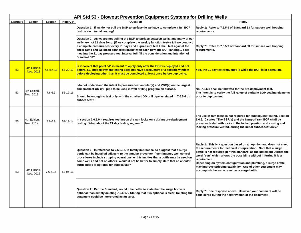
Question 1: If we do not pull the BOP to surface do we have to complete a full BOP
test on each initial landing?
Reply 1: Refer to 7.6.5.9 of Standard 53 for subsea well hopping
requirements.
Question 2: As we are not pulling the BOP to surface between wells, and many of our
wells are not 21 days long: (if we complete the weekly function tests) & If we conduct
a complete pressure test every 21 days and a -pressure test / shell test against the
shear rams and wellhead connector/gasket with each new site BOP landing... does
meeting the 21 day pressure test interval full-fill the consideration and intention of
Standard 53?
Reply 2: Refer to 7.6.5.9 of Standard 53 for subsea well hopping
requirements.
534th Edition,
Nov. 20127.6.5.4.1d 53-20-17
Is it correct that point "d" is meant to apply only after the BOP is deployed and not
before. I.E. predeployment testing does not have a frequency or a specific window
before deploying other than it must be completed at least once before deploying.
Yes, the 21 day test frequency is while the BOP is in operation.
534th Edition,
Nov. 20127.6.6.3 53-17-16
I do not understand the intent to pressure test annular(s) and VBR(s) on the largest
and smallest OD drill pipe to be used in well drilling program on surface.
Should be enough to test only with the smallest OD drill pipe as stated in 7.6.6.4 on
subsea test?
No, 7.6.6.3 shall be followed for the pre-deployment test.
The intent is to verify the full range of variable BOP sealing elements
prior to deployment.
534th Edition,
Nov. 20127.6.6.9 53-13-14
In section 7.6.6.9 it requires testing on the ram locks only during pre-deployment
testing. What about the 21 day testing regimen?
The use of ram locks is not required for subsequent testing. Section
7.6.6.10 states “The BSR(s) and the hang-off ram BOP shall be
pressure tested with locks in the locked position and closing and
locking pressure vented, during the initial subsea test only.”
Question 1: In reference to 7.6.6.17, is totally impractical to suggest that a surge
bottle can be installed adjacent to the annular preventer if contingency well control
procedures include stripping operations as this implies that a bottle may be used on
some wells and not on others. Would it not be better to simply state that an annular
surge bottle is optional for subsea use?
Reply 1: This is a question based on an opinion and does not meet
the requirements for technical interpretation. Note that a surge
bottle is not required per this standard, as the statement utilizes the
word “can” which allows the possibility without inferring it is a
requirement.
Depending on system configuration and plumbing, a surge bottle
may improve stripping capability. Use of other equipment may
accomplish the same result as a surge bottle.
Question 2: Per the Standard, would it be better to state that the surge bottle is
optional than simply deleting 7.6.6.17? Stating that it is optional is clear. Deleting the
statement could be interpreted as an error.
Reply 2: See response above. However your comment will be
considered during the next revision of the document.
534th Edition,
Nov. 20127.6.5.4.1a 53-04-17
534th Edition,
Nov. 20127.6.6.17 53-04-16
Page 21 of 27
Standard Edition Section Inquiry # Question Reply
API Std 53 - Blowout Prevention Equipment Systems for Drilling WellsLast update: August 12, 2015
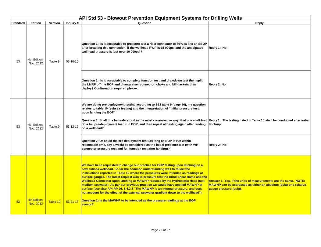
Question 1: Is it acceptable to pressure test a riser connector to 70% as like an SBOP
after breaking this connection, if the wellhead RWP is 15 000psi and the anticipated
wellhead pressure is just over 10 000psi?
Reply 1: No.
Question 2: Is it acceptable to complete function test and drawdown test then split
the LMRP off the BOP and change riser connector, choke and kill gaskets then
deploy? Confirmation required please.
Reply 2: No.
We are doing pre deployment testing according to S53 table 9 (page 86), my question
relates to table 10 (subsea testing) and the interpretation of “initial pressure test,
upon landing the BOP”
Question 1: Shall this be understood in the most conservative way, that one shall first
do a full pre-deployment test, run BOP, and then repeat all testing again after landing
on a wellhead?
Reply 1: The testing listed in Table 10 shall be conducted after initial
latch-up.
Question 2: Or could the pre-deployment test (as long as BOP is run within
reasonable time, say a week) be considered as the initial pressure test (with WH
connector pressure test and full function test after landing)?
Reply 2: No.
We have been requested to change our practice for BOP testing upon latching on a
new subsea wellhead. So far the common understanding was to follow the
instructions reported in Table 10 where the pressures were intended as readings at
surface gauges. The latest request was to pressure test the Blind Shear Rams and the
Wellhead Connector upon latching at MAWHP reduced by the Hydrostatic Head (test
medium seawater). As per our previous practice we would have applied MAWHP at
surface (see also API RP 96, 5.4.2.2 "The MAWHP is an internal pressure, and does
not account for the effect of the external seawater gradient down to the wellhead").
Question 1) Is the MAWHP to be intended as the pressure readings at the BOP
sensor?
Answer 1: Yes, if the units of measurements are the same. NOTE:
MAWHP can be expressed as either an absolute (psia) or a relative
gauge pressure (psig).
534th Edition,
Nov. 2012Table 9 53-10-16
534th Edition,
Nov. 2012Table 10 53-21-17
534th Edition,
Nov. 2012Table 9 53-12-16
Page 22 of 27
Standard Edition Section Inquiry # Question Reply
API Std 53 - Blowout Prevention Equipment Systems for Drilling WellsLast update: August 12, 2015
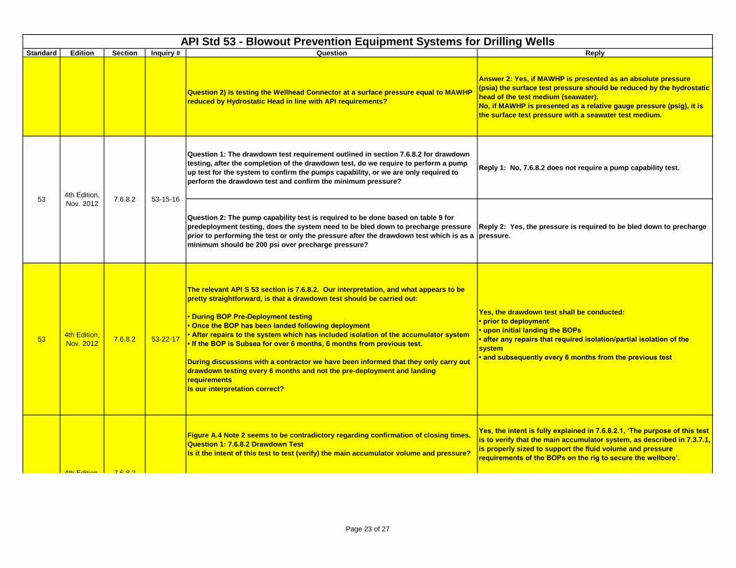
Question 2) Is testing the Wellhead Connector at a surface pressure equal to MAWHP
reduced by Hydrostatic Head in line with API requirements?
Answer 2: Yes, if MAWHP is presented as an absolute pressure
(psia) the surface test pressure should be reduced by the hydrostatic
head of the test medium (seawater).
No, if MAWHP is presented as a relative gauge pressure (psig), it is
the surface test pressure with a seawater test medium.
Question 1: The drawdown test requirement outlined in section 7.6.8.2 for drawdown
testing, after the completion of the drawdown test, do we require to perform a pump
up test for the system to confirm the pumps capability, or we are only required to
perform the drawdown test and confirm the minimum pressure?
Reply 1: No, 7.6.8.2 does not require a pump capability test.
Question 2: The pump capability test is required to be done based on table 9 for
predeployment testing, does the system need to be bled down to precharge pressure
prior to performing the test or only the pressure after the drawdown test which is as a
minimum should be 200 psi over precharge pressure?
Reply 2: Yes, the pressure is required to be bled down to precharge
pressure.
534th Edition,
Nov. 20127.6.8.2 53-22-17
The relevant API S 53 section is 7.6.8.2. Our interpretation, and what appears to be
pretty straightforward, is that a drawdown test should be carried out:
• During BOP Pre-Deployment testing
• Once the BOP has been landed following deployment
• After repairs to the system which has included isolation of the accumulator system
• If the BOP is Subsea for over 6 months, 6 months from previous test.
During discussions with a contractor we have been informed that they only carry out
drawdown testing every 6 months and not the pre-deployment and landing
requirements
Is our interpretation correct?
Yes, the drawdown test shall be conducted:
• prior to deployment
• upon initial landing the BOPs
• after any repairs that required isolation/partial isolation of the
system
• and subsequently every 6 months from the previous test
Figure A.4 Note 2 seems to be contradictory regarding confirmation of closing times.
Question 1: 7.6.8.2 Drawdown Test
Is it the intent of this test to test (verify) the main accumulator volume and pressure?
Yes, the intent is fully explained in 7.6.8.2.1, ‘The purpose of this test
is to verify that the main accumulator system, as described in 7.3.7.1,
is properly sized to support the fluid volume and pressure
requirements of the BOPs on the rig to secure the wellbore’.
534th Edition,
Nov. 20127.6.8.2 53-15-16
534th Edition,
Nov. 2012
7.6.8.2
Figure A.453-04-18
534th Edition,
Nov. 2012Table 10 53-21-17
Page 23 of 27
Standard Edition Section Inquiry # Question Reply
API Std 53 - Blowout Prevention Equipment Systems for Drilling WellsLast update: August 12, 2015
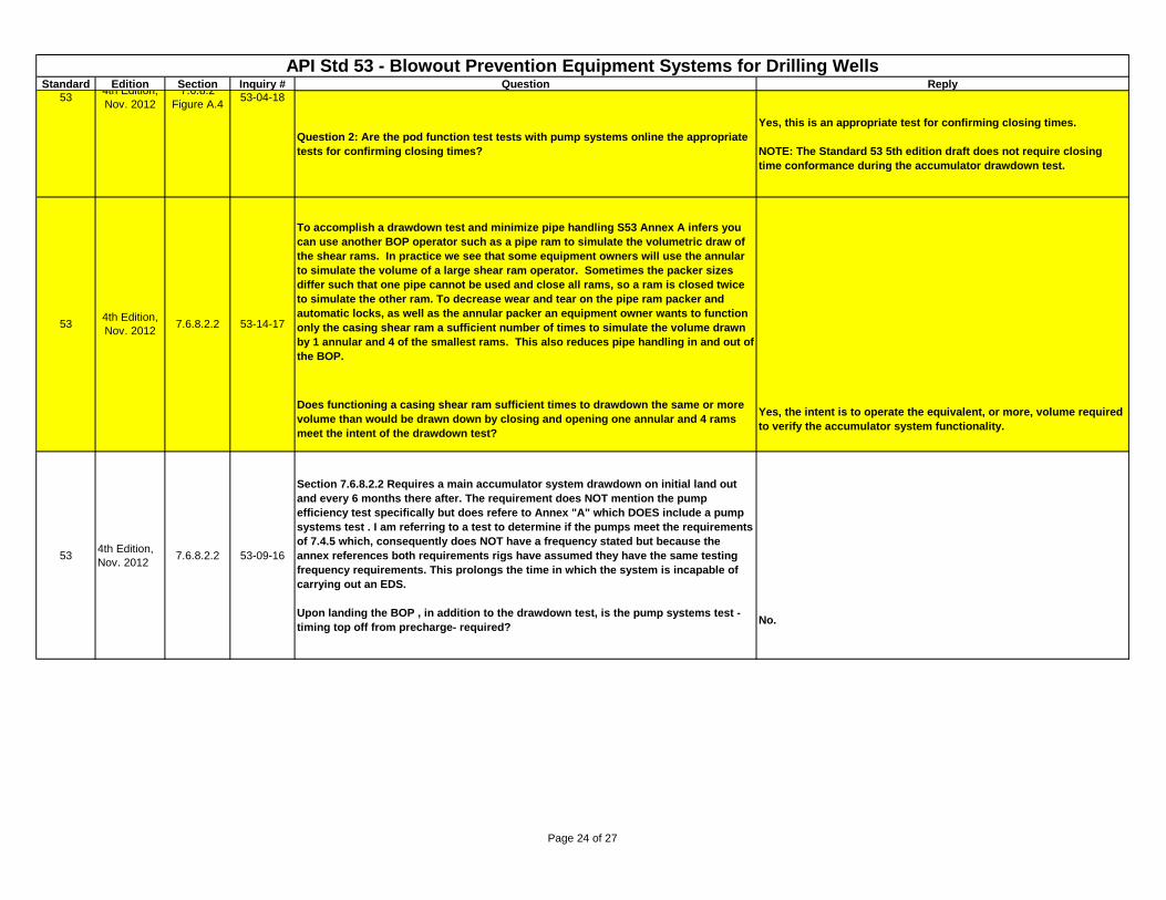
Question 2: Are the pod function test tests with pump systems online the appropriate
tests for confirming closing times?
Yes, this is an appropriate test for confirming closing times.
NOTE: The Standard 53 5th edition draft does not require closing
time conformance during the accumulator drawdown test.
To accomplish a drawdown test and minimize pipe handling S53 Annex A infers you
can use another BOP operator such as a pipe ram to simulate the volumetric draw of
the shear rams. In practice we see that some equipment owners will use the annular
to simulate the volume of a large shear ram operator. Sometimes the packer sizes
differ such that one pipe cannot be used and close all rams, so a ram is closed twice
to simulate the other ram. To decrease wear and tear on the pipe ram packer and
automatic locks, as well as the annular packer an equipment owner wants to function
only the casing shear ram a sufficient number of times to simulate the volume drawn
by 1 annular and 4 of the smallest rams. This also reduces pipe handling in and out of
the BOP.
Does functioning a casing shear ram sufficient times to drawdown the same or more
volume than would be drawn down by closing and opening one annular and 4 rams
meet the intent of the drawdown test?
Yes, the intent is to operate the equivalent, or more, volume required
to verify the accumulator system functionality.
534th Edition,
Nov. 20127.6.8.2.2 53-09-16
Section 7.6.8.2.2 Requires a main accumulator system drawdown on initial land out
and every 6 months there after. The requirement does NOT mention the pump
efficiency test specifically but does refere to Annex "A" which DOES include a pump
systems test . I am referring to a test to determine if the pumps meet the requirements
of 7.4.5 which, consequently does NOT have a frequency stated but because the
annex references both requirements rigs have assumed they have the same testing
frequency requirements. This prolongs the time in which the system is incapable of
carrying out an EDS.
Upon landing the BOP , in addition to the drawdown test, is the pump systems test -
timing top off from precharge- required?No.
534th Edition,
Nov. 20127.6.8.2.2 53-14-17
534th Edition,
Nov. 2012
7.6.8.2
Figure A.453-04-18
Page 24 of 27
Standard Edition Section Inquiry # Question Reply
API Std 53 - Blowout Prevention Equipment Systems for Drilling WellsLast update: August 12, 2015
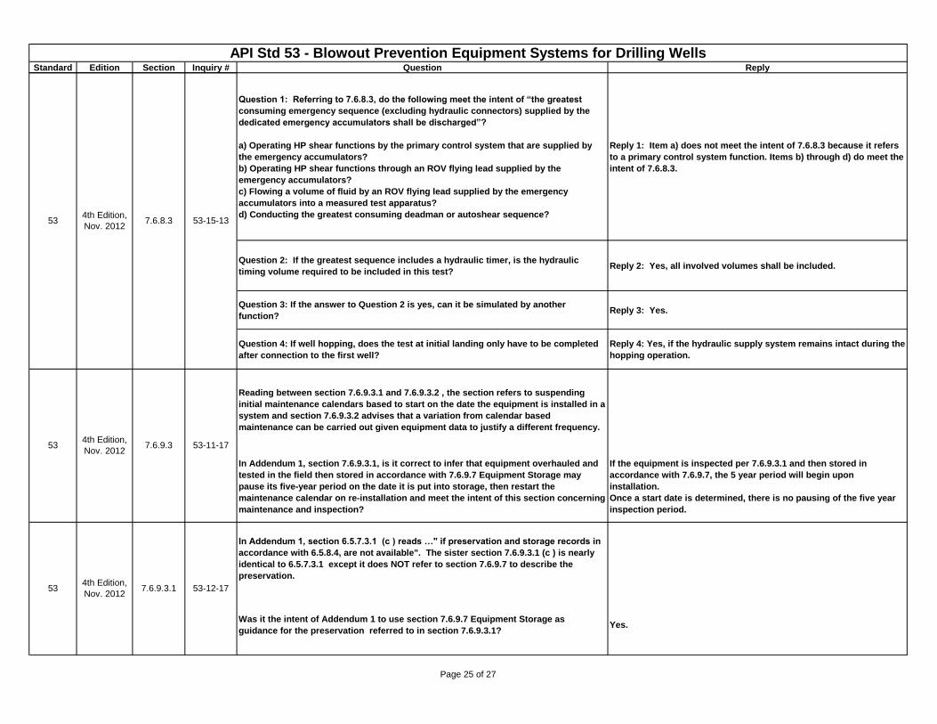
Question 1: Referring to 7.6.8.3, do the following meet the intent of “the greatest
consuming emergency sequence (excluding hydraulic connectors) supplied by the
dedicated emergency accumulators shall be discharged”?
a) Operating HP shear functions by the primary control system that are supplied by
the emergency accumulators?
b) Operating HP shear functions through an ROV flying lead supplied by the
emergency accumulators?
c) Flowing a volume of fluid by an ROV flying lead supplied by the emergency
accumulators into a measured test apparatus?
d) Conducting the greatest consuming deadman or autoshear sequence?
Reply 1: Item a) does not meet the intent of 7.6.8.3 because it refers
to a primary control system function. Items b) through d) do meet the
intent of 7.6.8.3.
Question 2: If the greatest sequence includes a hydraulic timer, is the hydraulic
timing volume required to be included in this test?Reply 2: Yes, all involved volumes shall be included.
Question 3: If the answer to Question 2 is yes, can it be simulated by another
function?Reply 3: Yes.
Question 4: If well hopping, does the test at initial landing only have to be completed
after connection to the first well?
Reply 4: Yes, if the hydraulic supply system remains intact during the
hopping operation.
Reading between section 7.6.9.3.1 and 7.6.9.3.2 , the section refers to suspending
initial maintenance calendars based to start on the date the equipment is installed in a
system and section 7.6.9.3.2 advises that a variation from calendar based
maintenance can be carried out given equipment data to justify a different frequency.
In Addendum 1, section 7.6.9.3.1, is it correct to infer that equipment overhauled and
tested in the field then stored in accordance with 7.6.9.7 Equipment Storage may
pause its five-year period on the date it is put into storage, then restart the
maintenance calendar on re-installation and meet the intent of this section concerning
maintenance and inspection?
If the equipment is inspected per 7.6.9.3.1 and then stored in
accordance with 7.6.9.7, the 5 year period will begin upon
installation.
Once a start date is determined, there is no pausing of the five year
inspection period.
In Addendum 1, section 6.5.7.3.1 (c ) reads …" if preservation and storage records in
accordance with 6.5.8.4, are not available". The sister section 7.6.9.3.1 (c ) is nearly
identical to 6.5.7.3.1 except it does NOT refer to section 7.6.9.7 to describe the
preservation.
Was it the intent of Addendum 1 to use section 7.6.9.7 Equipment Storage as
guidance for the preservation referred to in section 7.6.9.3.1? Yes.
534th Edition,
Nov. 20127.6.9.3 53-11-17
53-12-17534th Edition,
Nov. 20127.6.9.3.1
534th Edition,
Nov. 20127.6.8.3 53-15-13
Page 25 of 27
Standard Edition Section Inquiry # Question Reply
API Std 53 - Blowout Prevention Equipment Systems for Drilling WellsLast update: August 12, 2015
534th Edition,
Nov. 2012
7.6.9.3 &
6.2.5.153-27-16
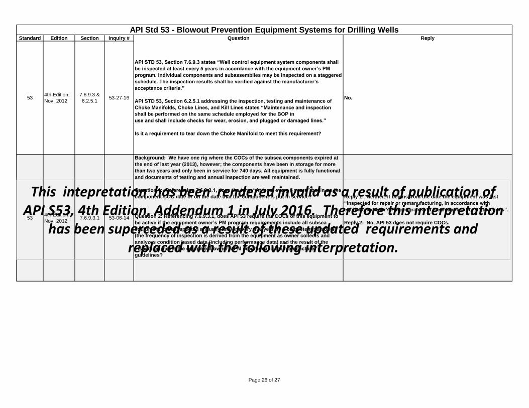
API STD 53, Section 7.6.9.3 states “Well control equipment system components shall
be inspected at least every 5 years in accordance with the equipment owner’s PM
program. Individual components and subassemblies may be inspected on a staggered
schedule. The inspection results shall be verified against the manufacturer’s
acceptance criteria.”
API STD 53, Section 6.2.5.1 addressing the inspection, testing and maintenance of
Choke Manifolds, Choke Lines, and Kill Lines states “Maintenance and inspection
shall be performed on the same schedule employed for the BOP in
use and shall include checks for wear, erosion, and plugged or damaged lines.”
Is it a requirement to tear down the Choke Manifold to meet this requirement?
No.
534th Edition,
Nov. 20127.6.9.3.1 53-06-14
Background: We have one rig where the COCs of the subsea components expired at
the end of last year (2013), however; the components have been in storage for more
than two years and only been in service for 740 days. All equipment is fully functional
and documents of testing and annual inspection are well maintained.
Question 1: Referencing 7.6.9.3.1, does the term “At least every 5 years” begin on the
component COC date or on the date that the component is put in service?
Question 2: Referencing 7.6.9.3.1, does API 53 require the COCs of this equipment to
be active if the equipment owner’s PM program requirements include all subsea
equipment to be inspected annually and/or every five year by a competent person(s)
(the frequency of inspection is derived from the equipment as owner collects and
analyzes condition based data (including performance data) and the result of the
inspection meets the equipment owner’s PM program and the manufacturer’s
guidelines?
Reply 1: Neither; it begins from the date the equipment was last
“inspected for repair or remanufacturing, in accordance with
equipment owner's PM program and the manufacturer’s guidelines”.
Reply 2: No, API 53 does not require COCs.
This intepretation has been rendered invalid as a result of publication of API S53, 4th Edition, Addendum 1 in July 2016. Therefore this interpretation
has been superceded as a result of these updated requirements and replaced with the following interpretation.
Page 26 of 27
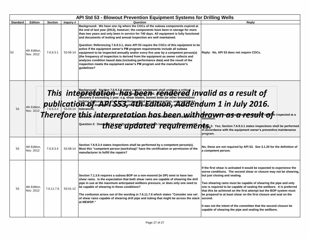
Standard Edition Section Inquiry # Question Reply
API Std 53 - Blowout Prevention Equipment Systems for Drilling WellsLast update: August 12, 2015
534th Edition,
Nov. 20127.6.9.3.1 53-06-14
Background: We have one rig where the COCs of the subsea components expired at
the end of last year (2013), however; the components have been in storage for more
than two years and only been in service for 740 days. All equipment is fully functional
and documents of testing and annual inspection are well maintained.
Question: Referencing 7.6.9.3.1, does API 53 require the COCs of this equipment to be
active if the equipment owner’s PM program requirements include all subsea
equipment to be inspected annually and/or every five year by a competent person(s)
(the frequency of inspection is derived from the equipment as owner collects and
analyzes condition based data (including performance data) and the result of the
inspection meets the equipment owner’s PM program and the manufacturer’s
guidelines?
Reply: No, API 53 does not require COCs.
534th Edition,
Nov. 20127.6.9.3.3 53-03-14
Background: Section 7.6.9.3.3 states certain equipment shall undergo a critical
inspection (internal/external visual, dimensional, NDE, etc.) annually, or upon
recovery if exceeding 1 year: e.g. shear blades, bonnet bolts (or other bonnet/door
locking devices), ram shaft button/foot, welded hubs, ram cavities, and ram blocks.
The actual dimensions shall be verified against the manufacturer’s allowable
tolerances.
Question 1: Was this meant to be a requirement for the listed example equipment?
Question 2: Does API 53 specify who determines which inspection method is used?
Reply 1: Yes; the example equipment listed shall be inspected at a
minimum.
Reply 2: Yes; Section 7.6.9.3.1 states inspections shall be performed
in accordance with the equipment owner’s preventive maintenance
program.
534th Edition,
Nov. 20127.6.9.3.4 53-08-14
Section 7.6.9.3.4 states inspections shall be performed by a competent person(s).
Must this "competent person (workshop)" have the certification or permission of the
manufacturer to fulfill the repairs?
No; these are not required by API 53. See 3.1.20 for the definition of
a competent person.
534th Edition,
Nov. 20127.6.11.7.6 53-01-12
Section 7.1.3.6 requires a subsea BOP on a non-moored (ie DP) semi to have two
shear rams. Is the expectation that both shear rams are capable of shearing the drill
pipe in use at the maximum anticipated wellbore pressure, or does only one need to
be capable of shearing in these conditions?
The confusion arises out of the wording in 7.6.11.7.6 which states "Consider one set
of shear rams capable of shearing drill pipe and tubing that might be across the stack
at MEWSP."
If the first shear is activated it would be expected to experience the
worse conditions. The second shear or closure may not be shearing,
but just closing and sealing.
Two shearing rams must be capable of shearing the pipe and only
one is required to be capable of sealing the wellbore. It is preferred
that this be achieved on the first attempt but the BOP system must
be prepared to at least shear on the first closure and seal on the
second.
It was not the intent of the committee that the second closure be
capable of shearing the pipe and sealing the wellbore.
This intepretation has been rendered invalid as a result of publication of API S53, 4th Edition, Addendum 1 in July 2016.
Therefore this interpretation has been withdrawn as a result of these updated requirements.
Page 27 of 27