
ANTI LOCK BRAKING SYSTEM (ABS) - · PDF fileAnti-lock Braking System 1. ... In this case the...
26
Anti-lock Braking System 1. INTRODUCTION Car manufacturers world wide are vying with each other to invent more reliable gadgets there by coming closer to the dream of the ‘Advanced safety vehicle’ or ‘Ultimate safety vehicle’, on which research and development has been going on for the past several year. Most of the newer vehicle models offer ABS as either standard or optional equipment .Wheel lockup during braking causes skidding which in turn cause a loss of traction and vehicle control. This reduces the steering ability to change direction. So the car slides out of control. But the road wheel that is still rotating can be steered. That is what ABS is all about. With such a system, the driver can brake hard, take the evasive action and still be in control of the vehicle in any road condition at any speed and under any load. ABS does not reduce stopping distance, but compensates the changing traction or tyre loading by preventing wheel lockup. During panic braking when the wheels are about to lockup, sensors sense that the wheel has just begun turning slower than others on the vehicle. So they momentarily reduce braking force on the affected wheel. This prevents sliding of the wheels on the pavement. When the wheel resumes rolling, full braking force is again applied. ABS repeats the process until there is no longer any need for modulated braking. ABS acts faster than any driver could, pumping the brakes several times per second. Depending on the type of system, ABS adjusts the braking force at each wheel or set of wheels, whereas a driver’s foot on the brake pedal operates all the brakes at once in normal braking. 1
Transcript of ANTI LOCK BRAKING SYSTEM (ABS) - · PDF fileAnti-lock Braking System 1. ... In this case the...

Anti-lock Braking System
1. INTRODUCTION
Car manufacturers world wide are vying with each other to
invent more reliable gadgets there by coming closer to the dream of
the ‘Advanced safety vehicle’ or ‘Ultimate safety vehicle’, on which
research and development has been going on for the past several
year. Most of the newer vehicle models offer ABS as either standard
or optional equipment .Wheel lockup during braking causes skidding
which in turn cause a loss of traction and vehicle control. This
reduces the steering ability to change direction. So the car slides out
of control. But the road wheel that is still rotating can be steered.
That is what ABS is all about. With such a system, the driver can
brake hard, take the evasive action and still be in control of the
vehicle in any road condition at any speed and under any load. ABS
does not reduce stopping distance, but compensates the changing
traction or tyre loading by preventing wheel lockup.
During panic braking when the wheels are about to
lockup, sensors sense that the wheel has just begun turning slower
than others on the vehicle. So they momentarily reduce braking force
on the affected wheel. This prevents sliding of the wheels on the
pavement. When the wheel resumes rolling, full braking force is
again applied. ABS repeats the process until there is no longer any
need for modulated braking. ABS acts faster than any driver could,
pumping the brakes several times per second. Depending on the
type of system, ABS adjusts the braking force at each wheel or set of
wheels, whereas a driver’s foot on the brake pedal operates all the
brakes at once in normal braking.
1

Anti-lock Braking System
2. CONCEPT OF ABS
The theory behind anti-lock brakes is simple. A skidding wheel
(where the tire contact patch is sliding relative to the road) has less
traction than a non-skidding wheel. If the vehicle have been stuck on
ice and if the wheels are spinning then the vehicle have no traction.
This is because the contact patch is sliding relative to the ice. By
keeping the wheels from skidding while you slow down, anti-lock
brakes benefit you in two ways: You'll stop faster, and you'll be able
to steer while you stop. Good drivers have always pumped the brake
pedal during panic stops to avoid wheel lock up and the loss of
steering control. ABS simply gets the pumping job done much faster
and in much precise manner than the fastest human foot.
2

Anti-lock Braking System
3. PRINCIPLES OF OPERATION OF SIMPLE
HYDRAULIC BRAKING SYSTEM.
A simple braking system consists of a master cylinder, and
four wheel cylinders. Every wheel cylinder contains two pistons which
move out words when the hydraulic fluid flows from the master
cylinder to the wheel cylinders through the suitable pipes or lines.
3

Anti-lock Braking System
Springs are used to hold the brake shoes on all four wheels.
When the brake pedal is pressed the piston in the master cylinder
forces the liquid out of the cylinder. This liquid presses the two
pistons in the wheel cylinders outwards. These two pistons push the
brake shoes out words. The brake shoes in turn press against the
brake drums; this stops the brake drum which will be rotating.
When the brake pedal is released the master cylinder is pushed
backwords.This is done by a spring fitted in the master cylinder. The
springs of the brake shoe brings the shoes closer. The liquid in the
wheel cylinder is pushed outwards through the pipes. It returns
through the pipes to the master cylinder. This is how the hydraulic
system of the four wheels operates
3.1 Master cylinder
4

Anti-lock Braking System
It consists of a reservoir feedhole, bypass port, primarypiston,
secondary piston .The liquid in the reservoir flows through bypass
port to the master cylinder. When the pedal is pressed the primary
piston moves to the left .when it crosses the bypass port the liquid is
forced along the pipe lines to the wheel cylinders. When the pedal is
released the primary piston is moved back wards .it is the spring,
which pushes the piston back wards. At the same time a partial
vacuum is developed in the space previously occupied by the spring.
4. PRINCIPLES OF ABS
5

Anti-lock Braking System
The brakes of vehicle not equipped with ABS will almost
immediately lock the wheels, when the driver suddenly applies the
brake. In this case the vehicle slides rather than rolls to a stop. The
skidding and lack of control was caused by the locking of wheels. The
release and reapply of the brake pedal will avoid the locking of the
wheels which in turn avoid the skidding. This is exactly what an
antilock braking system does.
4.1 Pressure modulation
When the brake pedal is pumped or pulsed the pressure is
quickly applied and released at the wheels. This is called pressure
modulation. Pressure modulation works to prevent the wheel locking.
ABS can modulate the pressure to the brake as often as 15 times per
seconds. By modulating the pressure to the brakes the friction
between the tires and the road is maintained and the vehicle is able
to come to the controllable stop.
6

Anti-lock Braking System
Steering is another important consideration. As long as a tire
doesn’t slip it goes only in the direction in which it is turned. But once
it is skid it has little or no directional stability.
The Maneuverability of the vehicle is reduced if the front
wheels are locked and the stability of the vehicle is reduced if the
rear wheels are locked.
ABS precisely controls the slip rate of the wheels to
ensure maximum grip force from the tyre and it there by ensures
maneuverability and stability of the vehicle. ABS control module
calculates the slip rate of the wheels based on the vehicle speed and
speed of the wheels, and then it controls the brake fluid pressure to
attain the target slip rate.
During ABS operation, the target slip rate can be from 10 to
30%. 0% slip means the wheel is rolling freely, while 100 % means
the wheel is fully locked. A slip rate of 25 % means the velocity of a
7

Anti-lock Braking System
wheel is 25 % less than that of a freely rolling wheel at the same
vehicle speed.
5. ABS COMPONENTS
Many different ABS are found on today’s vehicles. These
designs are varied by their basic layout, operation and components.
The ABS components can be divided into two categories.
1. Hydraulic components
2. Electrical/electronic components
Besides these normal and conventional brake parts are part of
the overall brake system.
5.1 Hydraulic components
• Accumulator
An accumulator is used to store hydraulic fluid to maintain high
pressure in the brake system and provide the residual pressure for
power assisted braking. Normally the accumulator is charged with
nitrogen gas and is an integral part of the modulator unit.
• Antilock hydraulic control valve assembly
This assembly controls the release and application of the brake
system pressure to the wheel brake assemblies. It may be of integral
type and non integral type. In integral type the unit is combined with
the power boost and master cylinder unit into one assembly. The non
8

Anti-lock Braking System
integral type is mounted externally from the master cylinder /power
booster unit and is located between the master cylinder and wheel
brake assembly. Both types generally contain solenoid valve that
control the releasing, holding and applying of brake system pressure.
• Booster pump
The booster pump is an assembly of an electric motor and
pump. The booster pump is used to provide pressurized hydraulic
fluid ABS. The pumps motor is controlled by systems control unit.
• Booster/Master cylinder assembly
It is referred as the hydraulic unit, contains the valves and
pistons needed to modulate hydraulic pressure in the wheel circuit
during the ABS operations.
• Fluid accumulator
Different than a pressure accumulator, fluid accumulator
temporarily store brake fluid, that is removed from the wheel brake
unit during ABS cycle. This fluid is then used by pump to build
pressure for the brake hydraulic system.
• Hydraulic control unit
This assembly contains solenoid valve, fluid accumulator, pump
and electric motor. The unit may have one pump and one motor or it
have one motor and two pumps.
• Main Valve
This is a two position valve and is also controlled by ABS
control module and is open only in the ABS mode. When open
pressurized brake fluid from the booster circuit is directed into the
master circuit to prevent excessive pedal travel.
• Modulator unit
9

Anti-lock Braking System
The modulator unit controls the flow of pressurized brake fluid
to the individual wheel circuits. Normally the modulator is made up of
solenoid that open and close valves, several valves that control flow
of fluid to wheel brake units and electrical relays that activate or
deactivate the solenoids through the commands of the control
module. This unit may also be called the hydraulic actuator, hydraulic
power unit or the electro hydraulic control valve.
• Solenoid valves
The solenoid valves are located in the modulator unit and are
electrically operated by signals from the control module. The control
module switches the solenoids on or off to increase, decrease, or
maintain the hydraulic pressure to the individual wheel units.
• Wheel circuit valves
Two solenoid valves are used to control each circuit or channel.
One controls the inlet valve of the circuit, the controls the outlet
valve .the position is determined by the control module. Outlet
valves are normally closed and inlet valves are normally open. Valves
are activated when abs control module switches 12 volts to the
circuit solenoids. During normal driving the circuits are not activated.
5.2 Electrical\ electronic components
• ABS control module
This small computer is normally mounted inside the trunk on
the wheel housing, mounted to the master cylinder or is part of the
hydraulic control unit. It monitors system operation and controls
antilock function when needed. The module relies on input from the
wheel speed sensors and feedback from the hydraulic unit to
determine if the abs is operating correctly and to determine when
the anti lock mode is required.
10

Anti-lock Braking System
• Brake pedal sensor
The antilock brake pedal sensor switch is normally closed.
When the brake pedal exceeds the antilock brake pedal sensor
switch setting during an antilock stop, the antilock brake control
module senses that the antilock brake pedal sensor switch is open
and grounds the pump motor relay coil. This energizes the relay and
turns the pump motor on. When the pump motor is running, the
hydraulic reservoir is filled with high pressure brake fluid and the
brake pedal will be pushed up until antilock brake pedal sensor
switch closes. when the antilock brake pedal sensor switch closes ,
the pump motor is turned off and the brake pedal will drop some with
each abs control cycle until the antilock brake pedal sensor switch
opens and the pump motor is turned on again .this minimizes pedal
feedback during abs cycling .
• Pressure differential switch
It is located in the modulator unit. This switch sends a signal to
the control module whenever there is an undesirable difference in
the hydraulic pressures with in the brake system.
• Relays
Relays are electromagnetic devices used to control a high
current circuit with a low current switching circuit. In abs relays are
used to switch motors and solenoids. A low current signal from the
control module energizes the relays that complete the electrical
circuit for the motor or solenoid.
• Toothed ring
It can be located on an axle shaft, differential gear or a wheels
hub. This ring is used with conjunction with the wheel speed sensor.
The ring has a number of teeth around its circumference. As the ring
rotates and each tooth passes by the wheel speed sensor, an ac
voltage signal is generated between the sensor and tooth.
• Wheel speed sensor
11

Anti-lock Braking System
It is mounted near the different toothed ring. As the rings teeth
rotate past the sensor an ac voltage is generated. as the teeth move
away from the sensor, the signal is broken until the next tooth comes
close to the sensor .the end result is a pulsing signal that is sent to
the control module. The control module translates the signal in to
wheel speed. The sensor is normally a small coil of wire with a
permanent magnet in its center.
6. TYPES OF ANTILOCK BRAKE SYSTEMS
One of the classifications of abs is integral and non integral
type.
Integral type they combine the master cylinder, hydraulic
booster and abs hydraulic circuit in to single hydraulic assembly.
In non integral type they use a conventional vacuum-assist
booster and master cylinder. In addition they can be classified
according to the control they provide.
6.1. Four channel, four sensors ABS
This is the best scheme. There is speed sensor
on all four wheels and a separate valve for all the four wheels. With
this set up the controller monitors each wheel individually to make
sure it is achieving maximum braking force.
6.2. Three channel, three sensor ABS
This scheme is commonly found on pick up trucks with four
wheels ABS, has a speed sensor and a valve for each of the front
12

Anti-lock Braking System
wheels, with one valve and one sensor for both rear wheels. The
speed sensor for the rear wheel is located in the rear axle.
This system provides individual control of the
wheels, so they can both achieve maximum braking force. The rear
wheels however are monitored together, they both have to start to
lock up before the abs will activate on the rear. With this system, it is
possible that one of the rear wheels will lock during a stop, reducing
brake effectiveness.
6.3. One channel, one sensor abs
This scheme is commonly found on pick up
trucks with rear wheel abs .it has one valve ,which controls both rear
wheels , and one speed sensor, located in the rear axle . This system
operates the same as the rear end of the rear channel system. The
rear wheels are monitored together and both have to start to lock up
before the abs kicks in. in this system is also possible that one of the
rear wheels will lock reducing brake effectiveness.
7. FOUR WHEEL SYSTEMThe hydraulic circuit for this type of system is an independent
four channel type. One for each wheel. The hydraulic control unit is a
separate unit. Normal braking is accompanied by conventional
vacuum power assist brake system.
The system prevents wheel lock up during an emergency stop
by modulating brake pressure. It allows the driver to maintain
steering control and stop the vehicle in the shortest possible distance
under most conditions. During ABS operation the driver will sense a
pulsation in the brake pedal and clicking sound.
13

Anti-lock Braking System
7.1 Operation
The ABS control module calculates the slip rate of the wheels
and control the brake fluid pressure to attain the target slip rate if
the control module senses that the wheel is about to lock based on
input sensor data, it pulses the normally open inlet solenoid valve
closed for that circuit. This prevents any more fluid from entering
that circuit. ABS control module then looks at the sensor signal from
the effected wheel again. If that wheel is still decelerating faster than
other three wheels it opens the normally closed out let solenoid valve
for that circuit. This dumps any pressure that is trapped between the
closed inlet valve and the brake back to the master cylinder
reservoir. Once the effected wheel returns to the same speed as the
other wheel, the control module returns the valve to the normal
condition allowing fluid flow to the effected brake.
Based on the input from vehicle speed and the wheel speed
sensor, the control module calculates the slip rate of each wheel, and
transmits a control signal to the modulator unit solenoid valve when
the slip rate is high.
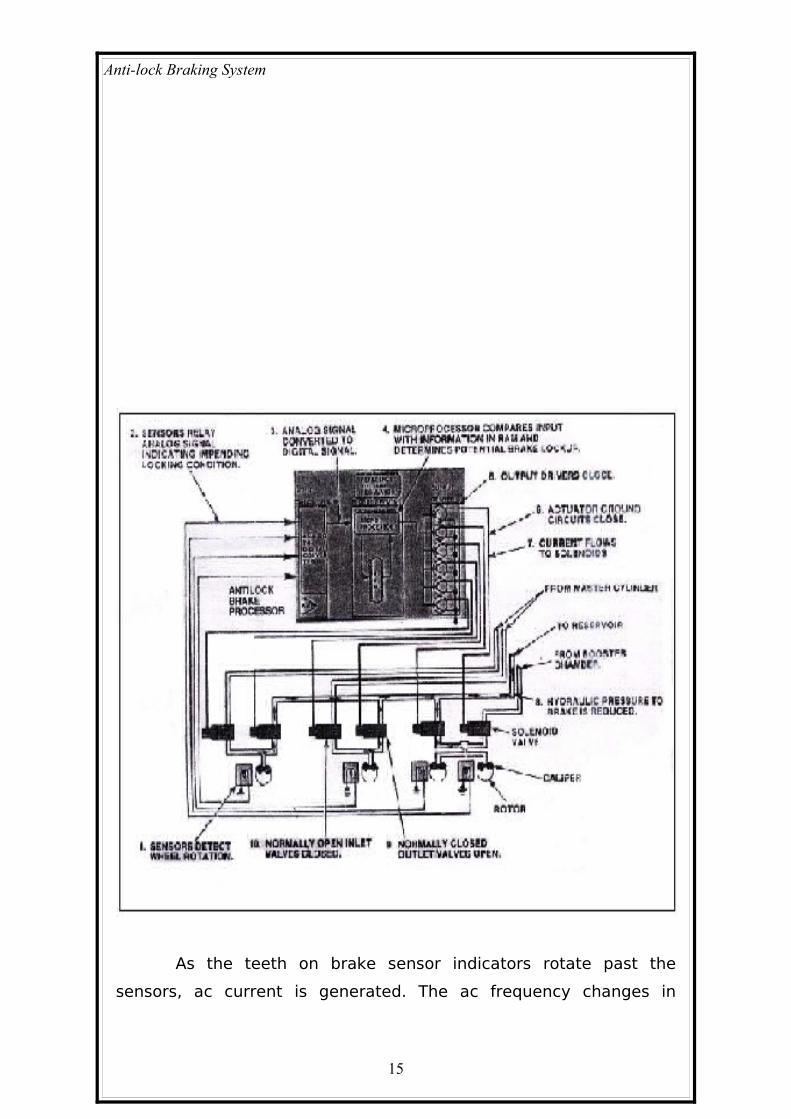
Wheel speed at each wheel is measured by variable
reluctance sensors and sensor indicators. The sensors operate on
magnetic induction principles.
14
Anti-lock Braking System
As the teeth on brake sensor indicators rotate past the
sensors, ac current is generated. The ac frequency changes in
15

Anti-lock Braking System
accordance with the wheel speed. The ABS control unit detects the
wheel sensor signal frequency and there by detects wheel speed.
7.2 FUNCTIONAL DIAGRAM OF FOUR CHANNEL ABS
16
Anti-lock Braking System
8. ADVANCEMENTS IN ABS
Some systems, which work with the ABS, are Automatic
traction control and Automatic stability control, which are discussed
below.
8.1 AUTOMATIC TRACTION CONTROL (ATC )
Automatic traction control systems apply the brakes when a
drive wheel attempts to spin and lose traction. The system works
best when one drive wheel is working on a good traction surface and
the other is not. The system also works well when the vehicle is
accelerating on slippery road surfaces, especially when climbing hills.
ATC is most helpful on four wheel or all wheel drive vehicles in which
loss of traction at one wheel could hamper driver control.
During road operation the ATC system uses an electronic
control module to monitor the wheel speed sensors. If a wheel enters
a loss of traction situation, the module applies braking force to the
wheel in trouble. Loss of traction is identified by comparing the
vehicle speed to the speed of the wheel. If there is a loss of traction
the speed of the wheel will be greater than expected for the
particular vehicle speed. ABS and ATC systems can be integral and
uses the common valves.
These systems are designed to reduce wheel slip and maintain
traction at the drive wheels when the road is wet or snow covered.
The control module monitors wheel speed. If during acceleration the
module detects drive wheel slip and if brakes are not applied, the
control module enters into the traction control mode. The inlet and
outlet solenoid valves are pulsed and allow the brake to be quickly
applied and released.
17

Anti-lock Braking System
In some systems when a loss of traction is sensed, it not only
cycles the brakes but signals the engine control module to retard
ignition timing and partially close the throttle as well, which in turn
reduces engine output.
Many systems are equipped with a dash mounted warning light
to alert the driver that the system is operating. There will also be a
manual cut off switch so that the driver can turn off ATC operation.
18

Anti-lock Braking System
8.2 AUTOMATIC STABILITY CONTROL
Like ATC, the stability control systems are linked with the ABS.
it can also be called Electronic Stability Programme (ESP). Stability
control systems momentarily apply the brakes at any one wheel to
correct over steer or under steer. The control unit receives signals
from the typical sensors plus a yaw, lateral acceleration (G-force) and
a steering angle sensor.
The system uses the angle of the steering wheel and the
speed of the four wheels to calculate the path chosen by the driver. It
then looks at lateral G-forces and vehicle yaw to measure where the
vehicle is going. (Yaw is defined as the natural tendency for a vehicle
to rotate on its vertical center axis). So it is also called Yaw control.
19

Anti-lock Braking System
Under steer is the condition in which the vehicle is slow to
respond to steering changes. Over steer occurs when the rear wheels
try to swing around causing the car to spin. When the system senses
under steer in a turn the brake at the inside rear wheel is applied.
During over steer the outside front brake is applied. Relaying on the
input from the sensors and computer programming the system
calculates if the vehicle is going exactly in the same direction in
which it is being steered. In case of any difference between what the
driver is asking and what the vehicle is doing, the system corrects
the situation by applying one of the right or left brakes.
20

Anti-lock Braking System
9. ADVANTAGES OF ABS
It allows the driver to maintain directional stability and control
over steering during braking
Safe and effective
Automatically changes the brake fluid pressure at each wheel
to maintain optimum brake performance.
ABS absorbs the unwanted turbulence shock waves and
modulates the pulses thus permitting the wheel to continue
turning under maximum braking pressure.
Disadvantages
It is very costly
Maintenance cost of a car equipped with ABS is more.
21

Anti-lock Braking System
10. CONCLUSION
ABS has been so far developed to a system, which
provides rapid, automatic braking in response to signs of incipient
wheel locking by alternatively increasing and decreasing hydraulic
pressure in the brake line
Statistics show that approximately 40 % of
automobile accidents are due to skidding. These problems commonly
occur on vehicle with conventional brake system which can be
avoided by adding devices called ABS
If there is an ABS failure, the system will revert to
normal brake operation. Normally the ABS warning light will turn on
and let the driver know there is a fault
22

Anti-lock Braking System
Bibliography
Automotive technology –Jack
erjavec
Automobile engineering – kirpal
Singh
www.howstuffworks .com
23

Anti-lock Braking System
ABSTRACT
Anti-Lock Braking Systems (ABS) are designed to maintain
driver control and stability of the car during emergency braking.
Locked wheels will slow a car down but will not provide steering
ability. ABS allows maximum braking to be applied while retaining
the ability to 'steer out of trouble'
The theory behind anti-lock brakes is simple.
A skidding wheel (where the tire contact patch is sliding relative to
the road) has less traction than a non-skidding wheel. By keeping the
wheels from skidding while you slow down, anti-lock brakes benefit
you in two ways: You'll stop faster, and you'll be able to steer while
you stop.
An ABS system monitors four wheel speed sensors to
evaluate wheel slippage. Slip can be determined by calculating the
ratio of wheel speed to vehicle speed, which is continuously
calculated from the four individual wheel speeds. During a braking
event, the function of the control system is to maintain maximum
possible wheel grip on the road - without the wheel locking - by
adjusting the hydraulic fluid pressure to each brake by way of
electronically controlled solenoid valves.
24

Anti-lock Braking System
CONTENTS
1. INTRODUCTION ....................................1
2. CONCEPT OF ABS..................................2
3. HYDRAULIC BRAKING SYSTEM................3
4. PRINCIPLES OF ABS.............................5
4.1 Pressure modulation
5. ABS COMPONENTS...............................7
5.1 Hydraulic components
5.2 Electrical\ electronic components
6. TYPES OF ANTILOCK BRAKE SYSTEMS. .11
6.1. Four channel, four sensors ABS
6.2. Three channel, three sensor ABS
6.3. One channel, one sensor abs
7. FOUR WHEEL SYSTEM.........................12
8. ADVANCEMENTS IN ABS......................15
8.1 automatic traction control
8.2 automatic stability control
9. ADVANTAGES OF ABS..........................19
25

Anti-lock Braking System
10. CONCLUSION......................................20
11. BIBLIOGRAPHY...................................21
26


![Anti Lock Braking System[1]](https://static.fdocuments.us/doc/165x107/577c859c1a28abe054bde223/anti-lock-braking-system1.jpg)


