ANTI LOCK BRAKING SYSTEM - 123seminarsonly.com · ANTI LOCK BRAKING SYSTEM Reneez.T.P Roll.No:43 S...
29
ANTI LOCK BRAKING SYSTEM Reneez.T.P Roll.No:43 S 7 ME
Transcript of ANTI LOCK BRAKING SYSTEM - 123seminarsonly.com · ANTI LOCK BRAKING SYSTEM Reneez.T.P Roll.No:43 S...

ANTI LOCK BRAKING SYSTEM
Reneez.T.P
Roll.No:43
S7 ME

Introduction
Wheel lockup during braking causes skidding which in turn cause a loss of traction and vehicle control
This reduces the steering ability to change direction. So the car slides out of control
With ABS system, the driver can brake hard, take the evasive action and still be in control of the vehicle in any road condition at any speed and under any load.

Concept of ABS
A skidding wheel (where the tire contact
patch is sliding relative to the road) has less
traction than a non-skidding wheel
By keeping the wheels from skidding while
you slow down, anti-lock brakes benefit you
in two ways:
You'll stop faster, and you'll be able to steer
while you stop

comparison

Simple hydraulic braking system
A simple braking system consists of a master cylinder, and four wheel cylinders
When the brake pedal is pressed the piston in the master cylinder forces the liquid out of the cylinder. This liquid presses the two pistons in the wheel cylinders outwards. These two pistons push the brake shoes out words.

Master cylinder
When the pedal is pressed
the primary piston moves to
the left .
when it crosses the bypass
port the liquid is forced
along the pipe lines to the
wheel cylinders.
When the pedal is released
the primary piston is moved
back wards .it is the spring,
which pushes the piston
back wards

Principles of ABS
The skidding and lack of control was caused by the locking of wheels.
The release and reapply of the brake pedal will avoid the locking of the wheels which in turn avoid the skidding.
This is exactly what an antilock braking system does.

Pressure modulation
When the brake pedal is pumped or pulsed the
pressure is quickly applied and released at the wheels.
This is called pressure modulation. Pressure
modulation works to prevent the wheel locking.
ABS can modulate the pressure to the brake as often
as 15 times per seconds
ABS precisely controls the slip rate of the wheels to
ensure maximum grip force from the tyre and it there
by ensures maneuverability and stability of the vehicle

Slip rate
During ABS operation, the
target slip rate can be
from 10 to 30%.
0% slip means the wheel
is rolling freely, while 100
% means the wheel is
fully locked.
A slip rate of 25 % means
the velocity of a wheel is
25 % less than that of a
freely rolling wheel at the
same vehicle speed

ABS components
Hydraulic components
1. Accumulator
An accumulator is used to store hydraulic fluid to
maintain high pressure in the brake system and provide
the residual pressure for power assisted braking
2. Antilock hydraulic control valve assembly
This assembly controls the release and application of
the brake system pressure to the wheel brake
assemblies .
It may be of integral type and non integral type


3. Booster pump
The booster pump is an assembly of an electric motor and pump. The booster pump is used to provide pressurized hydraulic fluid ABS
4. Booster/Master cylinder assembly
It is referred as the hydraulic unit, contains the valves and pistons needed to modulate hydraulic pressure in the wheel circuit during the ABS operations
5. Fluid accumulator
accumulator temporarily stored brake fluid that is removed from the wheel brake unit during ABS cycle. This fluid is then used by pump to build pressure for the brake hydraulic system.

6. Hydraulic control unit
This assembly contains solenoid valve, fluid accumulator, pump and electric motor. The unit may have one pump and one motor or it have one motor and two pumps.
7. Main Valve
This is a two position valve and is also controlled by ABS control module and is open only in the ABS mode.
8. Modulator unit
The modulator unit controls the flow of pressurized brake fluid to the individual wheel circuits. Normally the modulator is made up of solenoid that open and close valves
9. Solenoid valves
The solenoid valves are located in the modulator unit and are electrically operated by signals from the control module

Electrical\ electronic components
1. ABS control module fig
This small computer is normally mounted inside the trunk on the wheel housing ,mounted to the master cylinder or is part of the hydraulic control unit. It monitors system operation and controls antilock function when needed
2. Brake pedal sensor
The antilock brake pedal sensor switch is normally closed. when the brake pedal exceeds the antilock brake pedal sensor switch setting during an antilock stop , the antilock brake control module senses that the antilock brake pedal sensor switch is open
3. Wheel speed sensor fig
It is mounted near the different toothed ring . as the rings teeth rotate past the sensor an ac voltage is generated

Types of antilock brake systems
Four channel, four sensor ABS
This is the best scheme. there is speed sensor on all four wheels and a separate valve for all the four wheels.
Three channel , three sensor ABS
This scheme is commonly found on pick up trucks with four wheels ABS, has a speed sensor and a valve for each of the front wheels, with one valve and one sensor for both rear wheels.
• One channel , one sensor ABS
it has one valve ,which controls both rear wheels , and one speed sensor, located in the rear axle .

Four wheel system
The hydraulic circuit for this type of system is
an independent four channel type. One for
each wheel. The hydraulic control unit is a
separate unit
The system prevents wheel lock up during an
emergency stop by modulating brake
pressure

Operation
fig

Advancements
AUTOMATIC TRACTION CONTROL
(ATC)
AUTOMATIC STABILITY CONTROL

AUTOMATIC TRACTION CONTROL (ATC)
Automatic traction control
systems apply the brakes when
a drive wheel attempts to spin
and lose traction.
The system works best when
one drive wheel is working on a
good traction surface and the
other is not.
The system also works well
when the vehicle is accelerating
on slippery road surfaces,
especially when climbing hills.
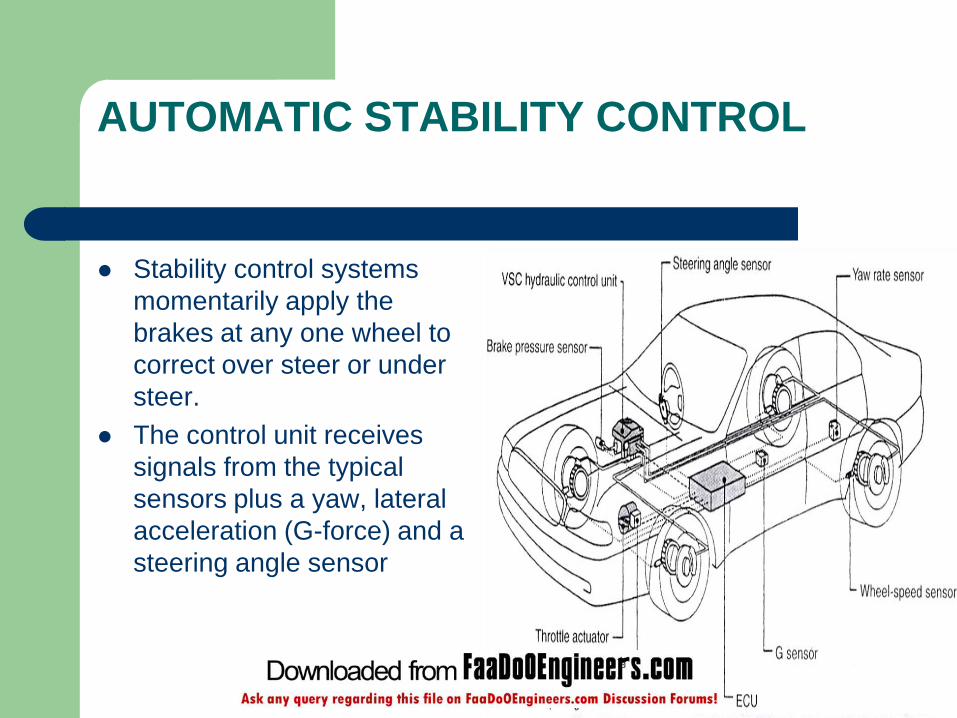
AUTOMATIC STABILITY CONTROL
Stability control systems
momentarily apply the
brakes at any one wheel to
correct over steer or under
steer.
The control unit receives
signals from the typical
sensors plus a yaw, lateral
acceleration (G-force) and a
steering angle sensor

ESP

Advantages
It allows the driver to maintain directional stability
and control over steering during braking
Safe and effective
Automatically changes the brake fluid pressure at
each wheel to maintain optimum brake performance.
ABS absorbs the unwanted turbulence shock waves
and modulates the pulses thus permitting the wheel
to continue turning under maximum braking
pressure.
Disadvantages
It is very costly
Maintenance cost of a car equipped with
ABS is more.

Conclusion
Statistics show that approximately 40 % of automobile accidents are due to skidding.
These problems commonly occur on vehicle with conventional brake system which can be avoided by adding devices called ABS
If there is an ABS failure, the system will revert to normal brake operation. Normally the ABS warning light will turn on and let the driver know there is a fault

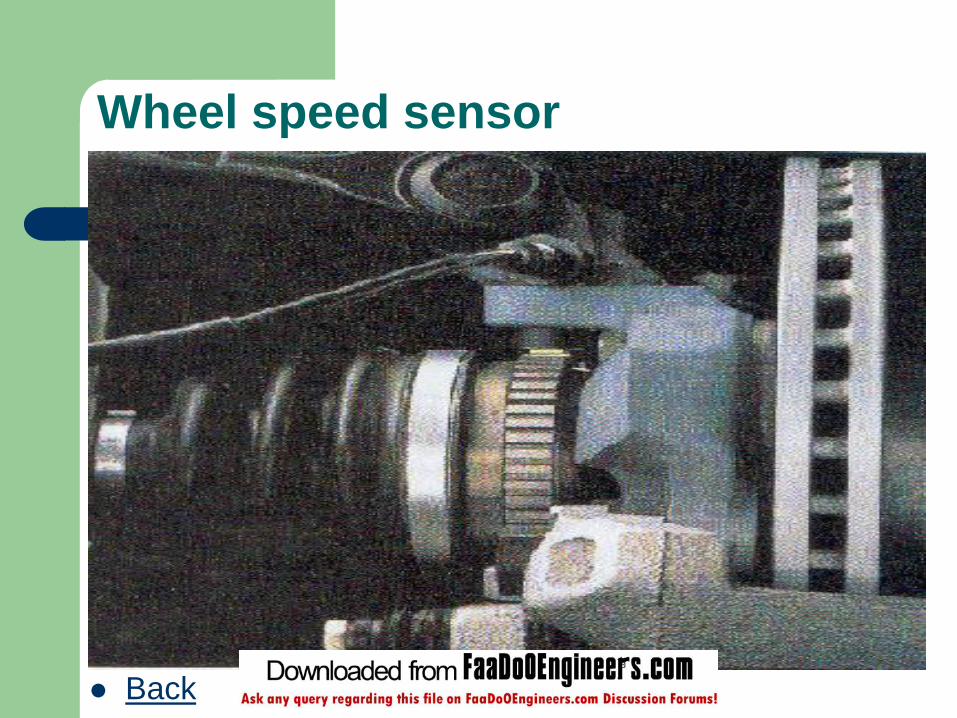
Wheel speed sensor
Back

ABS control module
Back

Back