ANSI DIMENSIONAL MAG DRIVE - finishthompson
37
A N S I D I M E N S I O N A L M A G D R I V E METAL MAG LINE TM UCII GROUP: UC2110, UC2110L, UC3110, UC3158, UC328, UC3210, UC436, UC438, UC4310H, & UC6410 OPERATIONAL MANUAL P/N 108725 R17 Record your Model and Serial Number here. MODEL NUMBER SERIAL NUMBER
Transcript of ANSI DIMENSIONAL MAG DRIVE - finishthompson

1
A N S I D I M E N S I O N A L M A G D R I V E
M E T A L M A G L I N ETM
UCII GROUP: UC2110, UC2110L, UC3110, UC3158, UC328,UC3210, UC436, UC438, UC4310H, & UC6410
OPERATIONAL MANUAL P/N 108725 R17
Record your Model and Serial Number here.
MODEL NUMBER SERIAL NUMBER
2
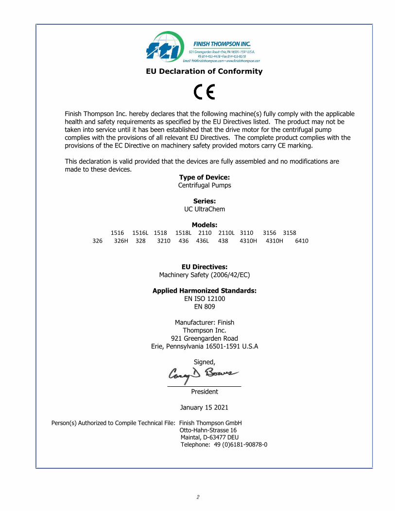
EU Declaration of Conformity
Finish Thompson Inc. hereby declares that the following machine(s) fully comply with the applicable health and safety requirements as specified by the EU Directives listed. The product may not be taken into service until it has been established that the drive motor for the centrifugal pump complies with the provisions of all relevant EU Directives. The complete product complies with the provisions of the EC Directive on machinery safety provided motors carry CE marking.
This declaration is valid provided that the devices are fully assembled and no modifications are made to these devices.
Type of Device: Centrifugal Pumps
Series: UC UltraChem
Models: 1516 1516L 1518 1518L 2110 2110L 3110 3156 3158
326 326H 328 3210 436 438 4310H 4310H 6410
EU Directives: Machinery Safety (2006/42/EC)
Applied Harmonized Standards: EN ISO 12100
EN 809
Manufacturer: Finish Thompson Inc.
921 Greengarden Road Erie, Pennsylvania 16501-1591 U.S.A
Signed,
President
January 15 2021
Person(s) Authorized to Compile Technical File: Finish Thompson GmbH Otto-Hahn-Strasse 16 Maintal, D-63477 DEU Telephone: 49 (0)6181-90878-0
436L

3
EU Declaration of Conformity
Manufactured by:
Finish Thompson, Inc. 921 Greengarden Road Erie, Pennsylvania 16501 U.S.A. Phone: 1-(814)-455-4478 Fax 1-(814)-455-8518 Email: [email protected] Web: www.finishthompson.com
Finish Thompson declares under our sole responsibility that the product listed below conforms to the relevant provisions of EU directive 2014/34/EU of 26 February 2014 for equipment and protective systems intended for use in potentially explosive atmospheres, and is certified for safe use in Atmosphere Group IIB/IIIC category 2 areas.
This declaration applies to Finish Thompson, Inc. ATEX UC Series pumps with the brass bump ring designated by the letter “B” after the motor adapter in the model number. Pumps and their model number may also contain many different combinations of magnet sets, flange port connections, coupling type, bushings, shafts, o-rings, impellers, motor adapters and other options.
Models: UC1516”B”, UC1516L”B”, UC1518”B”, UC1518L”B”, UC326”B”, UC326H”B”, UC2110”B”, UC2110L”B”, UC3110 “B”, UC3156"B", UC3158”B”, UC328”B”, UC3210"B", UC436”B”, UC438”B”, UC4310H”B” & UC6410”B”.
This product has used the following harmonized standards to verify conformance:
Non-electrical equipment for potentially explosive atmospheres: EN ISO 80079-36:2016 Basic Methods and Requirements. Non-electrical equipment intended for use in potentially explosive atmospheres: EN ISO 80079-37:2016 Protection by construction safety “ch.” and control of ignition source “bh”
This product must not be used in areas other than specified above. If in doubt consult an authorized
distributor, or refer to the manufacturer Finish Thompson.
Approved by:
Date: 8/22/2017
1026II 2GD Ex h IIB T6…T3 GbEx h IIIC T6…T3 Db
FTZU 03 ATEX A049-03 FTZU 11 ATEX A268-11

4
Table of Contents
Warranty Statement ................................................................................................................................ 5Safety Precautions .................................................................................................................................. 5ATEX Safety Precautions .............. .......................................................................................................... 6Surface Temperature for ATEX Pumps …………………………………………………………...……. 6ULTRAChem Features ............................................................................................................................. 7ULTRAChem Capabilities.......................................................................................................................... 7Maximum Allowable Horsepower............................................................................................................. 7Minimum Allowable Flow Rate ................................................................................................................ 8Model Codes and Abbreviations……………………………………………………………………....... 8Unpacking and Inspection........................................................................................................................ 9Model Number and Serial Number........................................................................................................... 9
InstallationPumps with Motors ................................................................................................................................. 9Pumps without Motors ...................................................................................................................... 9-10Foundation .............................................................................................................................................11Baseplate ............................................................................................................................................... 11Piping................................................................................................................................................11-12Electrical ................................................................................................................................................12
OperationPre-operation Inspection........................................................................................................................12Start-up and Operation......................................................................................................................11-13Shutdown...............................................................................................................................................13
Disassembly/ReassemblyDisassembly of Pump End ................................................................................................................13-14Disassembly of Power End (Motor Side) ...............................................................................................14Examination ...........................................................................................................................................15Replacing Wear Components .................................................................................................................17Shaft Support/Front Thrust Washer .......................................................................................................16Impeller Thrust Ring ..............................................................................................................................16Rear Sealing Ring ..................................................................................................................................17Impeller Assembly Removal and Replacement…………………………………………..................17-23Impeller Bushings.................................................................................................................................. 24Power End Reassembly ........................................................................................................................ 24Pump End Reassembly .................................................................................................................... 24-25Troubleshooting .....................................................................................................................................26
General Notes
Important Notice ................................................................................................................................... 26
Chemical Reaction Disclaimer................................................................................................................ 26
Helpful Hints ..........................................................................................................................................26
Ordering Spare Parts ............................................................................................................................ 26
Exploded View Drawing ........................................................................................................................ 27
Parts List .......................................................................................................................................... 28-32
Impeller Identification............................................................................................................................ 33
Impeller Part Numbers ..................................................................................................................... 34-36
5
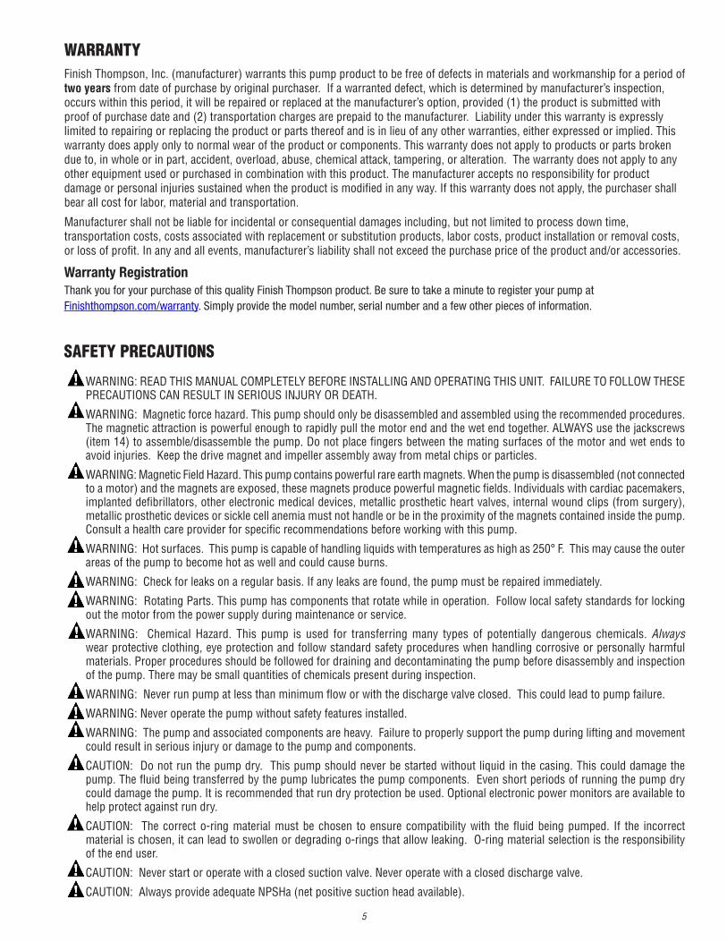
WARRANTY
WARNING: READ THIS MANUAL COMPLETELY BEFORE INSTALLING AND OPERATING THIS UNIT. FAILURE TO FOLLOW THESE PRECAUTIONS CAN RESULT IN SERIOUS INJURY OR DEATH.
WARNING: Magnetic force hazard. This pump should only be disassembled and assembled using the recommended procedures. The magnetic attraction is powerful enough to rapidly pull the motor end and the wet end together. ALWAYS use the jackscrews (item 14) to assemble/disassemble the pump. Do not place fingers between the mating surfaces of the motor and wet ends to avoid injuries. Keep the drive magnet and impeller assembly away from metal chips or particles.
WARNING: Magnetic Field Hazard. This pump contains powerful rare earth magnets. When the pump is disassembled (not connected to a motor) and the magnets are exposed, these magnets produce powerful magnetic fields. Individuals with cardiac pacemakers, implanted defibrillators, other electronic medical devices, metallic prosthetic heart valves, internal wound clips (from surgery), metallic prosthetic devices or sickle cell anemia must not handle or be in the proximity of the magnets contained inside the pump. Consult a health care provider for specific recommendations before working with this pump.
WARNING: Hot surfaces. This pump is capable of handling liquids with temperatures as high as 250° F. This may cause the outer areas of the pump to become hot as well and could cause burns.
WARNING: Check for leaks on a regular basis. If any leaks are found, the pump must be repaired immediately.
WARNING: Rotating Parts. This pump has components that rotate while in operation. Follow local safety standards for locking out the motor from the power supply during maintenance or service.
WARNING: Chemical Hazard. This pump is used for transferring many types of potentially dangerous chemicals. Always wear protective clothing, eye protection and follow standard safety procedures when handling corrosive or personally harmful materials. Proper procedures should be followed for draining and decontaminating the pump before disassembly and inspection of the pump. There may be small quantities of chemicals present during inspection.
WARNING: Never run pump at less than minimum flow or with the discharge valve closed. This could lead to pump failure.
WARNING: Never operate the pump without safety features installed.
WARNING: The pump and associated components are heavy. Failure to properly support the pump during lifting and movement could result in serious injury or damage to the pump and components.
CAUTION: Do not run the pump dry. This pump should never be started without liquid in the casing. This could damage the pump. The fluid being transferred by the pump lubricates the pump components. Even short periods of running the pump dry could damage the pump. It is recommended that run dry protection be used. Optional electronic power monitors are available to help protect against run dry.
CAUTION: The correct o-ring material must be chosen to ensure compatibility with the fluid being pumped. If the incorrect material is chosen, it can lead to swollen or degrading o-rings that allow leaking. O-ring material selection is the responsibility of the end user.
CAUTION: Never start or operate with a closed suction valve. Never operate with a closed discharge valve.
CAUTION: Always provide adequate NPSHa (net positive suction head available).
SAFETY PRECAUTIONS
Finish Thompson, Inc. (manufacturer) warrants this pump product to be free of defects in materials and workmanship for a period of two years from date of purchase by original purchaser. If a warranted defect, which is determined by manufacturer’s inspection, occurs within this period, it will be repaired or replaced at the manufacturer’s option, provided (1) the product is submitted with proof of purchase date and (2) transportation charges are prepaid to the manufacturer. Liability under this warranty is expressly limited to repairing or replacing the product or parts thereof and is in lieu of any other warranties, either expressed or implied. This warranty does apply only to normal wear of the product or components. This warranty does not apply to products or parts broken due to, in whole or in part, accident, overload, abuse, chemical attack, tampering, or alteration. The warranty does not apply to any other equipment used or purchased in combination with this product. The manufacturer accepts no responsibility for product damage or personal injuries sustained when the product is modified in any way. If this warranty does not apply, the purchaser shall bear all cost for labor, material and transportation.
Manufacturer shall not be liable for incidental or consequential damages including, but not limited to process down time, transportation costs, costs associated with replacement or substitution products, labor costs, product installation or removal costs, or loss of profit. In any and all events, manufacturer’s liability shall not exceed the purchase price of the product and/or accessories.
Warranty RegistrationThank you for your purchase of this quality Finish Thompson product. Be sure to take a minute to register your pump at Finishthompson.com/warranty. Simply provide the model number, serial number and a few other pieces of information.

6
UC Series:
The pump is designed for
Protection ControlA power monitor, flow switch, pressure switch or similar device must be used to protect against dry running, closed discharge valve or decoupling. Any of these conditions could lead to a rise in surface temperature of the pump.
Construction MaterialsPump must be manufactured with a bronze bump ring and have the designation “B” in the pump part number. The bronze bump ring is pressed into the motor adapter and prevents sparking should the motor bearings fail and the outer drive magnet runs out of round.
GroundingStatic sparking can cause an explosion. When operating in a hazardous area or pumping a hazardous fluid the entire pump system must be grounded to prevent static discharge. Before operating the pump, ensure the electrical continuity throughout the pumping system and earth ground is 1 Ohm or less. If greater than 1 Ohm, re-check all grounding connections.
Elastomer SelectionProper o-ring material must be chosen for the fluid being pumped. Improper material selection could lead to swelling and be a possible source of leaks. This is the responsibility of the end user.
LeaksThe pump must be checked for leaks on a regular basis. If leaks are noticed, the pump must be repaired or replaced immediately.
Temperature Classification The surface temperature of the UC Series pumps depends upon the temperature of the fluid that is being pumped. The following chart lists different fluid temperatures and the corresponding pump surface temperature.
CleaningThe pump must be cleaned on a regular basis to avoid dust build up greater than 5 mm.
Motor Rotation TestPump must be full of liquid with no trapped air in the suction and discharge lines before the rotation of the motor is checked. Do not operate pump until it is full of liquid.
Start upThe pump must be filled from a flooded suction tank (gravity) or primed with liquid from an outside source. Open the inlet (suction) and discharge valves completely and allow the pump to fill with liquid. Close the discharge valve. Turn the pump on and slowly open the discharge valve. Adjust the flow rate and pressure by regulating the discharge valve. Do not attempt to adjust the flow with the suction valve.
MaintenanceThe recommended maintenance schedule depends upon the nature of the fluid being pumped and the specific application. If the pump is used on a clean fluid, it is recommended that the pump be removed from service and examined after six months of operation or after 2,000 hours of operation. If the pump is used on fluids with solids, high temperatures or other items that could cause accelerated wear, then this initial examination should be sooner.
After the initial examination of the internal components and wear items are measured, a specific maintenance schedule can be determined. For best results, it is recommended that the pump be removed from service annually for examination.
ADDITIONAL SAFETY PRECAUTIONS FOR ATEX COMPLIANT PUMPS
II 2GD Ex h IIB T6…T3 GbEx h IIIC T6…T3 Db1026
Fluid Temperature
Maximum Surface Temperature
Temperature Class
Maximum Allowable Surface Temperature
31ºC (88ºF) 67ºC (153ºF) T6 85ºC 91ºC (195ºF) 97ºC (206ºF) T4 135ºC121ºC (250ºF) 133ºC (272ºF) T3 200ºC

7
ULTRAChem Features
ULTRAChem Capabilities
Maximum Allowable HorsepowerDo not exceed the maximum horsepower rating for the pump coupling. Refer to the chart below. Use the first six or seven characters from the model number listed on the label found on the motor adapter.
Maximum Working Pressure: 300 psi (20.7 bar)Maximum Temperature: 250°F (121° C), (E-magnet up to 220° F (104° C) Application Dependent ) Minimum Temperature: -20°F (-29° C)Maximum Flow: 1450 US GPM (329 m3/hr) Maximum Head: 492 ft (150 m)Maximum Viscosity: 200 cPMaximum Noise Level: 80 dBA (pump only)Solids: Maximum particle size is 50 microns for slurries and 1/64” (.4 mm) for in-frequent particles. Maximum hardness is 80 HS. Maximum concentration is 5% by weight. If solids are being pumped, it is recommended the pump have the silicon carbide bushings and thrust washer.
The Finish Thompson ULTRAChem is a sealless, magnetically driven, ANSI dimensional, ETFE lined chemical pump. It has been specifically designed for corrosive chemical applications in a wide range of industrial services.
The ULTRAChem features a closed impeller, suction straightening vanes, balanced axial thrust with a rear sealing ring, balance holes and balanced radial thrust due to the modified concentric or partial splitter volute shapes.
The ULTRAChem uses standard silicon carbide shaft, thrust bearings and bushings (optional carbon bushings allow limited run dry capabilities). All metallic components are steel or cast ductile iron.
High strength, rare earth neodymium iron boron magnets are used for maximum power and reliability. Finish Thompson’s patented magnetic technology ensures an extraordinarily strong, secure coupling between the motor and pump.
The barrier consists of a precision molded carbon filled ETFE liner with an external aramid fabric/epoxy shell for superior mechanical strength and elimination of eddy currents in the magnetic coupling. The sealless design virtually eliminates maintenance and environmental emissions.
The Easy Set drive feature makes installation of the outer drive quick and easy. It eliminates the need for measuring and ensures that the inner and outer magnets are perfectly aligned to transmit maximum power.
The ULTRAChem has drive hubs and motor adapters for a complete range of NEMA and IEC motor frames. The suction and discharge flanges can be drilled to fit ANSI 150#, 300# and ISO PN40 bolting dimensions.
These features combine to provide our customers with a pump that offers a broad operating range with outstanding reliability due to minimum hydraulic loads and premium materials of construction.
FTI’s ATEX compliant pumps meet Directive 2014/34/EU for use in potentially explosive atmospheres.
Magnet Set
60 Hz (3500 RPM)
50 Hz (2900 RPM)
30 Hz (1750 RPM)
25Hz (1450 RPM)
HP kW HP kW HP kW HP kW
B 20 15 15 11 10 7.5 7.5 5.5
C 40 30 30 22 20 15 15 11
D 60 45 50 37 30 22 25 18.5
E 75 55 60 45 40 30 30 22
F 100 75 75 55 50 37 40 30
8
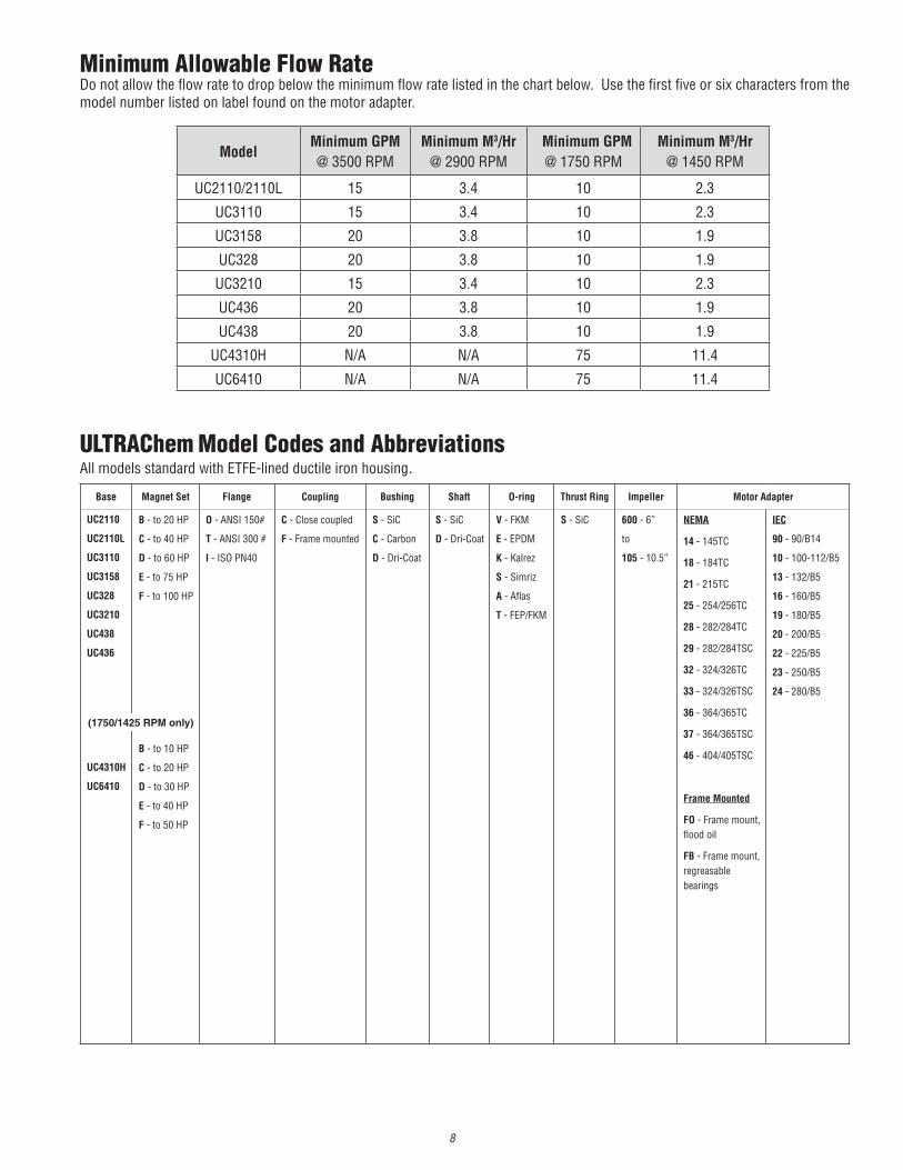
ULTRAChem Model Codes and AbbreviationsAll models standard with ETFE-lined ductile iron housing.
Minimum Allowable Flow RateDo not allow the flow rate to drop below the minimum flow rate listed in the chart below. Use the first five or six characters from the model number listed on label found on the motor adapter.
Model Minimum GPM @ 3500 RPM
Minimum M3/Hr@ 2900 RPM
Minimum GPM@ 1750 RPM
Minimum M3/Hr@ 1450 RPM
UC2110/2110L 15 3.4 10 2.3
UC3110 15 3.4 10 2.3
UC3158 20 3.8 10 1.9
UC328 20 3.8 10 1.9
UC3210 15 3.4 10 2.3
UC436 20 3.8 10 1.9
UC438 20 3.8 10 1.9
UC4310H N/A N/A 75 11.4
UC6410 N/A N/A 75 11.4
Base Magnet Set Flange Coupling Bushing Shaft O-ring Thrust Ring Impeller Motor Adapter
UC2110
UC2110L
UC3110
UC3158
UC328
UC3210
UC438
UC436
UC4310H
UC6410
B - to 20 HP
C - to 40 HP
D - to 60 HP
E - to 75 HP
F - to 100 HP
B - to 10 HP
C - to 20 HP
D - to 30 HP
E - to 40 HP
F - to 50 HP
O - ANSI 150#
T - ANSI 300 #
I - ISO PN40
C - Close coupled
F - Frame mounted
S - SiC
C - Carbon
D - Dri-Coat
S - SiC
D - Dri-Coat
V - FKM
E - EPDM
K - Kalrez
S - Simriz
A - Aflas
T - FEP/FKM
S - SiC 600 - 6”
to
105 - 10.5”
NEMA
14 - 145TC
18 - 184TC
21 - 215TC
25 - 254/256TC
28 - 282/284TC
29 - 282/284TSC
32 - 324/326TC
33 - 324/326TSC
36 - 364/365TC
37 - 364/365TSC
46 - 404/405TSC
Frame Mounted
FO - Frame mount, flood oil
FB - Frame mount, regreasable bearings
IEC
90 - 90/B14
10 - 100-112/B5
13 - 132/B5
16 - 160/B5
19 - 180/B5
20 - 200/B5
22 - 225/B5
23 - 250/B5
24 - 280/B5
(1750/1425 RPM only)

9
Unpacking and InspectionUnpack the pump and examine for any signs of shipping damage. If damage is detected, save the packaging and notify the carrier immediately.
To install the pump, follow the installation instructions provided.
WARNING: The pump and associated components are heavy. Failure to properly support the pump during lifting and movement could result in serious injury or damage to the pump and components.
Model Number and Serial Number Record the model number and serial number for future reference. Use the location provided on the front cover of this manual. This is important information when ordering replacement parts or when technical assistance is required. The model and serial number are found on a label located on the motor adapter.
InstallationTo install a motor to a pump end, see section Assembly of Pumps without Motors, and then proceed to section Foundation.Note: A hydrostatic test was performed prior to shipment. It is normal for a small amount of water to be retained inside the pump.
Vertical OperationUC Series pumps can be installed in a vertical position (either pump facing up or pump facing down) but the motor MUST be an IEC 100 frame motor or larger. IEC motors have a bolt in the motor shaft that prevents the outer drive from moving. IEC 90 frame and smaller motors contain a wavy washer on both ends of the motor shaft that can allow the outer drive to potentially rub. The pump must be securely fastened to a solid material capable of absorbing any vibration that the pump will produce.
Pumps with Motors: Proceed to Foundation Section.
Fig 1
Fig 2
Pumps without Motors:1. Prepare to install the motor on the pump. Carefully place the motor and pump end on a suitable, level work surface a nonmagnetic surface is preferred). Make sure the work surface is free of metal chips or particles. Magnetic Force Hazard. This pump should only be disassembled and assembled using the recommended procedures. The magnetic attraction is powerful enough to rapidly pull the motor end and the wet end together. ALWAYS use the jackscrews (item14) to assemble/disassemble the pump. Do not place fingers between the mating surfaces of the motor and wet ends to avoid injuries. Keep the drive magnet and impeller assembly away from metal chips or particles.
CAUTION: Keep the drive hub away from the open end of the motor adapter and barrier. Strong magnetic attraction could allow the drive hub to enter the motor adapter resulting in injury or damage.
2. Using a 24 mm socket, unbolt the wet end (items 1-7) from the motor adapter by removing the (4) M16 hex head cap screws (item 15). Make sure the (2) jackscrews (item 14) are fully extended. Using a 24 mm socket turn the jackscrews clockwise until they are fully extended. See figure 1.
3. Coat the motor shaft with anti-seize paste. Slide the drive shaft adapter (item 8B) onto the motor shaft with the key in the keyway. Slide the adapter until the retaining ring touches the end of the motor shaft. See figure 2.
A. For installation onto NEMA motor frames: i. Using a 3/16”- bit and torque wrench, tighten both setscrews to 228 in-lbs. (25.8N-m)
B. For installation onto IEC motor frames: i. Install flat washer, lock washer, and bolt (items 18, 19 & 20) into the end of the motor shaft and then tighten to the following torque settings: IEC 90 B5- M8-1.25: 120 in-lbs (13.7 N-m) IEC 100/112 B5- M10-1.5: 250 in-lbs (28.2 N-m) IEC 132 B5- M12-1.75: 35 ft-lbs (47.5 N-m) IEC 160/180 B5- M16-2.0: 90 ft-lbs (122 N-m) IEC 200/225 B5- M20-2.5: 90 ft-lbs (122 N-m) IEC 250/280 B5- M20-2.5 x 40: 90 ft-lbs (122 N-m) IEC 250/280 B5- M20-2.5 x 40: 90ft-lbs (122 N-m)

10
Note: The shaft adapter is held to a tight tolerance (+0.0005”/-0.0000) to the motor shaft, so it may be necessary to tap the shaft adapter with a soft faced mallet or heat it with an oven/induction heater to around 180° F (82° C) to fully seat it. Be careful to not damage the shaft adapter during this process.
4. Install vapor protection o-ring (item 25) in the groove on the back of the motor adapter (item 9) use petroleum jelly or similar substance to help hold the o-ring in place. Slide the motor adapter over the shaft adapter and attach it to the motor face. Use the (4) supplied hex head cap screws & lock washers (items 16 & 16A) and torque evenly to the following values. See figure 3. NEMA 145TC: 3/8-16, 15 ft-lbs (20.3 N-m) NEMA 184/215/254/284/286: ½-13, 75 ft-lbs (101.7 N-m) NEMA 324/364: 5/8-11, 90 ft-lbs (122 N-m) IEC 90 B5: M10-1.5, 20 ft-lbs (27.1 N-m) IEC 100/112/132 B5: M12-1.75, 35 ft-lbs (47.5 N-m) IEC 160/180/200/225 B5: M16-2.0, 90 ft-lbs (122 N-m) IEC 250/280 B5: 5/8” - 11 x 2”, 90 ft-lbs (122 N-m)
5. Lightly coat the bore of the magnet hub (item 8A) with anti-seize paste. See figure 4.
6. Using the two threaded studs, carefully slide the magnet hub onto the shaft adapter. See figure 5. It maybe necessary to lightly tap, or use the supplied hex head bolts to pull the hub into position. Use the supplied (2) hex head bolts, (4) lock washers and (2) hex nuts (items 21, 22 & 23) to secure the magnets into position. Torque the bolts and nuts (M8) to 120 in-lbs (13.7 N-m). See figure 5.
Note: Use supplied cardboard to help protect the outer drive magnets from damage from tools. Be sure to remove the tube after drive is securely attached. Save tube should any future repairs be necessary. If your pump did not ship with one of these tubes, please consult the spare parts list for ordering information.
7. Lubricate the vapor protection o-ring (item 24) on the front of the motor adapter with petroleum jelly. See figure 6.
8. Carefully slide the wet end towards the motor adapter until it touches the jackscrews (item 14) there will be some magnetic attraction. Make sure the (2) jackscrews are fully extended. See figure 7.
9. Slowly and evenly turn the jackscrews counterclockwise to allow the wet end to slowly slide into the motor adapter. When the jackscrews are fully retracted, lift the wet end slightly and slide it onto the motor adapter’s locating flange. If necessary the M16 motor adapter bolts may be used to draw the pump end onto the motor adapter. Be careful not to cut or damage the vapor protection o-ring (item 24).
10. Bolt the wet end to the motor adapter by reinstalling the (4) M16 hex head cap screws & lock washers (items 15 & 15A) and torque evenly to 90 ft-lbs (122 N-m). See figure 8.
Lightly coat with anti-sieze
Fig 3
Fig 4 Fig 5
Fig 8Fig 7Fig 6
11
Foundation1. The foundation that the pump will be sitting on should be strong enough to support the pump as well as absorb any vibration that the pump will produce. A concrete platform should be acceptable. Bolts embedded in the concrete can be placed by using a template or drawing. The use of a pipe sleeve larger than the bolt will compensate for base movement for final bolt location.
2. You must allow a gap no greater that 1-1/2” between base and foundation for grouting
Base plate1. The base plate of the ULTRAChem must be placed on the foundation using two sets of wedges or shims. These shims should be placed on each side of the foundation bolts. Provide enough clearance for proper grouting.
2. Remove any water or other debris from the anchor bolt holes prior to grouting.
3. Carefully lower the base plate onto the foundation bolts.
4. Level the base plate to within 1/8-inch over the length and 1/16-inch over the width. This can be done by adjusting the wedges.
5. Hand tighten the bolts.
Grout the base plate
1. Ensure that the area that is to be grouted is clean. Follow instructions from the grout manufacturer.
2. Erect a dam around the foundation. Insure that the foundation is thoroughly wetted.
3. Pour grout in the dam and completely fill under and around the base plate to the level of the dam. Make sure that any air bubbles are removed as it is poured. It is recommended that non-shrinking grout be used.
4. Permit the grout to set at least 48 hours.
5. Tighten the foundation bolts.
CAUTION: Do not operate the pump until it is securely fastened!
Piping1. The pump should be installed as near to the suction source as possible.
2. It is recommended that pipes are supported as close as possible to the pump and all flanges line up. This will minimize any pipe strain.
3. The suction side of the pump should be as straight and short as possible to minimize pipe friction or a length at least ten times the inlet diameter should follow any elbows.
4. The suction or inlet line should be at least as large as the suction inlet port or one pipe size larger so that it does not affect the NPSHa. Do not reduce the suction line size.
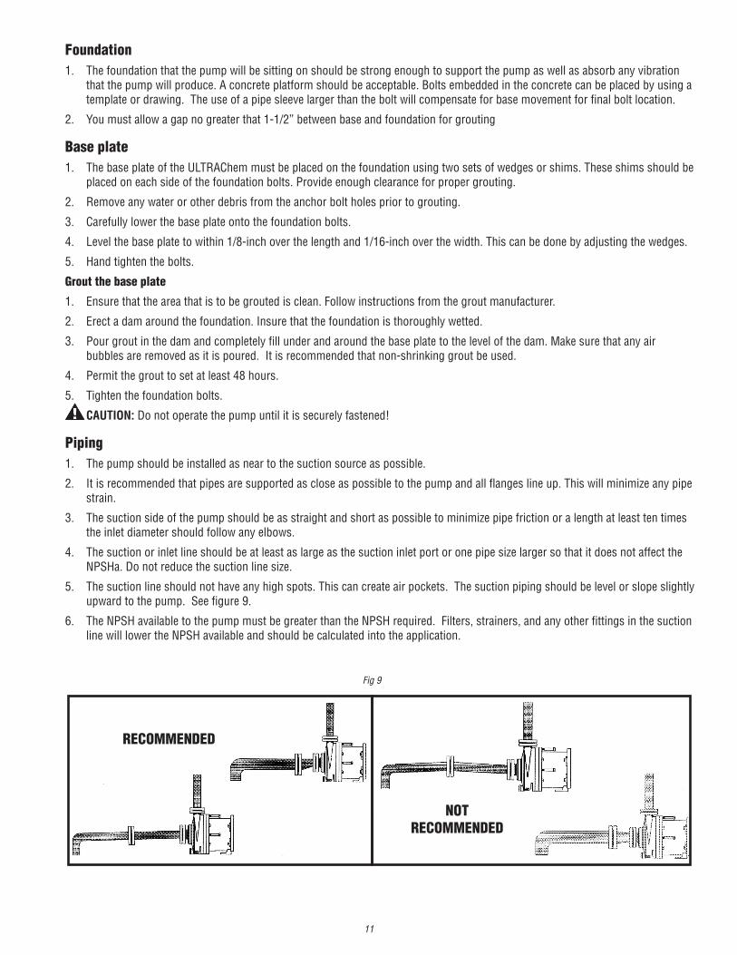
5. The suction line should not have any high spots. This can create air pockets. The suction piping should be level or slope slightly upward to the pump. See figure 9.
6. The NPSH available to the pump must be greater than the NPSH required. Filters, strainers, and any other fittings in the suction line will lower the NPSH available and should be calculated into the application.
RECOMMENDED
NOTRECOMMENDED
Fig 9

12
Motor/ElectricalOnly qualified personnel trained in the safe installation and operation of this equipment should install the motor. Install the motor according to National Electric Code, NEMA MG-2, IEC standards requirements, and/or applicable local electric codes. The voltage and frequency variations of the power supply should never exceed the limits established in the applicable standard. Prior to connecting to the power line, check nameplate voltage, rotation connection, and ensure proper grounding. Sufficient ventilation area should be provided to insure proper operation and cooling of the motor. The motor must be installed with a suitable overload protection circuit. For three-phase motors, it is recommended to install a phase failure protection device. Download the motor manual from the specific motor manufacturer’s website for additional information concerning motor installation, safety, and maintenance instructions.
Wire the motor for clockwise rotation when facing the fan end of the motor.
CAUTION: Do not operate the pump to check rotation until pump is full of liquid or damage may occur even if the motor is “bumped” to check motor rotation direction.
Check all electrical connections with the wiring diagram on the motor. Make sure the voltage, frequency, phase, and amp draw comply with supply circuit.
If utilized, verify that power monitors or variable frequency drives have been properly installed according to the manufacturer’s instructions.
OperationPre-Operation InspectionPrior to the first operation of the pump, perform the following inspections:
WARNING: Lock out power to the driver to prevent accidental motor start-up and physical injury.
1. Insert a screwdriver through the fan cover and rotate the fan. It should move without restrictions.
2. Verify that all flange and hold down bolts are tightened.
Start-up and Operation1. This pump must be filled from a flooded suction tank (gravity) or primed with liquid from an outside source.
2. The ULTRAChem is not self-priming.
3. Ensure that the pump is full of liquid and the inlet (suction) valve is open.
4. Open the outlet (discharge) valve completely and then close it so that there is no trapped air in the suction and discharge line.
5. After the pump is full of liquid, check that the rotation of the motor/ pump is in the correct direction. This can be achieved by jogging the motor for approximately ½ second. The motor rotation can be observed from the fan end. Correct rotation when viewed from the fan end is clockwise.
6. Note: A pump running backwards will pump but at a greatly reduced flow and pressure.
7. Turn the pump on. Slowly open the discharge valve. Check pump for proper flow and pressure, and that pump runs without excessive noise or vibration.
8. Keep the suction valve in the fully open position. Never use the suction valve to regulate the flow rate. Use the discharge valve only.
Note: It is not necessary to jog the motor or adjust the valves on subsequent pump starts provided that the pump and piping remain full of liquid.
7. A check valve and a control valve (if used) or isolation valve should be installed on the discharge line. The control valve is used for regulating system flow. An isolation valve is used to make the pump accessible for maintenance. It is recommended that the control or isolation valve be closed prior to stopping or starting the pump. The check valve is installed to protect the pump against water hammer damage. These recommendations are particularly important when the static discharge head is high.
8. It is advisable to install a flush system in the piping to allow the pump to be flushed before the pump is removed from service.
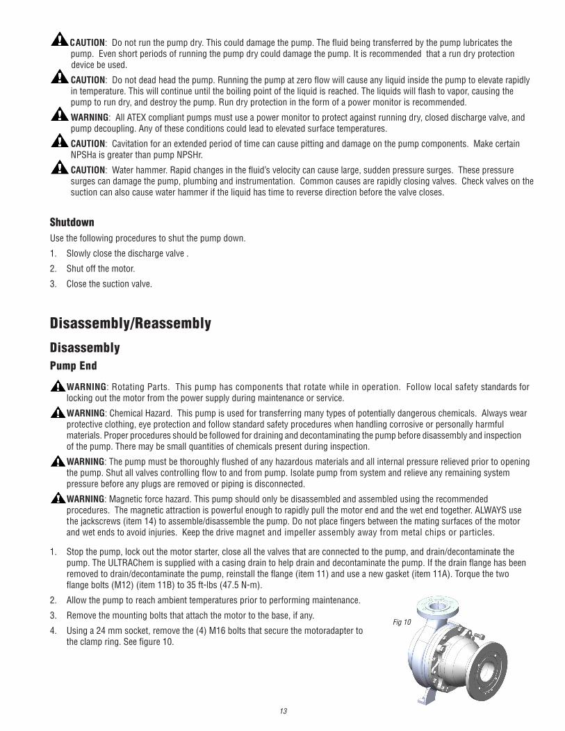
9. When connecting piping to the pump suction and discharge flanges, if lock washers are used, install under the head of the bolt. See figure 10.
Fig 10
13
CAUTION: Do not run the pump dry. This could damage the pump. The fluid being transferred by the pump lubricates the pump. Even short periods of running the pump dry could damage the pump. It is recommended that a run dry protection device be used.
CAUTION: Do not dead head the pump. Running the pump at zero flow will cause any liquid inside the pump to elevate rapidly in temperature. This will continue until the boiling point of the liquid is reached. The liquids will flash to vapor, causing the pump to run dry, and destroy the pump. Run dry protection in the form of a power monitor is recommended.
WARNING: All ATEX compliant pumps must use a power monitor to protect against running dry, closed discharge valve, and pump decoupling. Any of these conditions could lead to elevated surface temperatures.
CAUTION: Cavitation for an extended period of time can cause pitting and damage on the pump components. Make certain NPSHa is greater than pump NPSHr.
CAUTION: Water hammer. Rapid changes in the fluid’s velocity can cause large, sudden pressure surges. These pressure surges can damage the pump, plumbing and instrumentation. Common causes are rapidly closing valves. Check valves on the suction can also cause water hammer if the liquid has time to reverse direction before the valve closes.
Shutdown Use the following procedures to shut the pump down.
1. Slowly close the discharge valve .
2. Shut off the motor.
3. Close the suction valve.
Disassembly/Reassembly
DisassemblyPump End
WARNING: Rotating Parts. This pump has components that rotate while in operation. Follow local safety standards for locking out the motor from the power supply during maintenance or service.
WARNING: Chemical Hazard. This pump is used for transferring many types of potentially dangerous chemicals. Always wear protective clothing, eye protection and follow standard safety procedures when handling corrosive or personally harmful materials. Proper procedures should be followed for draining and decontaminating the pump before disassembly and inspection of the pump. There may be small quantities of chemicals present during inspection.
WARNING: The pump must be thoroughly flushed of any hazardous materials and all internal pressure relieved prior to opening the pump. Shut all valves controlling flow to and from pump. Isolate pump from system and relieve any remaining system pressure before any plugs are removed or piping is disconnected.
WARNING: Magnetic force hazard. This pump should only be disassembled and assembled using the recommended procedures. The magnetic attraction is powerful enough to rapidly pull the motor end and the wet end together. ALWAYS use the jackscrews (item 14) to assemble/disassemble the pump. Do not place fingers between the mating surfaces of the motor and wet ends to avoid injuries. Keep the drive magnet and impeller assembly away from metal chips or particles.
1. Stop the pump, lock out the motor starter, close all the valves that are connected to the pump, and drain/decontaminate the pump. The ULTRAChem is supplied with a casing drain to help drain and decontaminate the pump. If the drain flange has been removed to drain/decontaminate the pump, reinstall the flange (item 11) and use a new gasket (item 11A). Torque the two flange bolts (M12) (item 11B) to 35 ft-lbs (47.5 N-m).
2. Allow the pump to reach ambient temperatures prior to performing maintenance.
3. Remove the mounting bolts that attach the motor to the base, if any.
4. Using a 24 mm socket, remove the (4) M16 bolts that secure the motoradapter to the clamp ring. See figure 10.
Fig 10
14
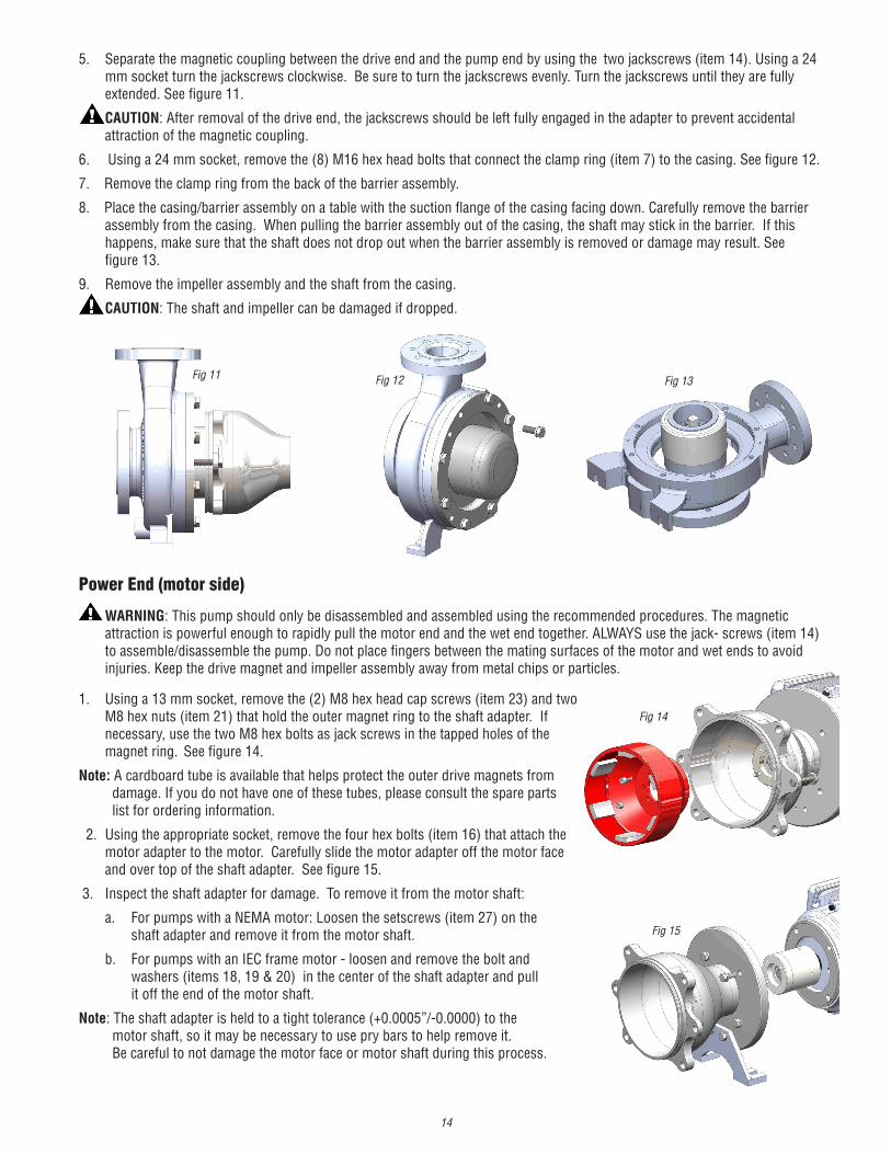
5. Separate the magnetic coupling between the drive end and the pump end by using the two jackscrews (item 14). Using a 24 mm socket turn the jackscrews clockwise. Be sure to turn the jackscrews evenly. Turn the jackscrews until they are fully extended. See figure 11.
CAUTION: After removal of the drive end, the jackscrews should be left fully engaged in the adapter to prevent accidental attraction of the magnetic coupling.
6. Using a 24 mm socket, remove the (8) M16 hex head bolts that connect the clamp ring (item 7) to the casing. See figure 12.
7. Remove the clamp ring from the back of the barrier assembly.
8. Place the casing/barrier assembly on a table with the suction flange of the casing facing down. Carefully remove the barrier assembly from the casing. When pulling the barrier assembly out of the casing, the shaft may stick in the barrier. If this happens, make sure that the shaft does not drop out when the barrier assembly is removed or damage may result. See figure 13.
9. Remove the impeller assembly and the shaft from the casing.
CAUTION: The shaft and impeller can be damaged if dropped.
Fig 13Fig 12Fig 11
Power End (motor side)
WARNING: This pump should only be disassembled and assembled using the recommended procedures. The magnetic attraction is powerful enough to rapidly pull the motor end and the wet end together. ALWAYS use the jack- screws (item 14) to assemble/disassemble the pump. Do not place fingers between the mating surfaces of the motor and wet ends to avoid injuries. Keep the drive magnet and impeller assembly away from metal chips or particles.
1. Using a 13 mm socket, remove the (2) M8 hex head cap screws (item 23) and two M8 hex nuts (item 21) that hold the outer magnet ring to the shaft adapter. If necessary, use the two M8 hex bolts as jack screws in the tapped holes of the magnet ring. See figure 14.
Note: A cardboard tube is available that helps protect the outer drive magnets from damage. If you do not have one of these tubes, please consult the spare parts list for ordering information.
2. Using the appropriate socket, remove the four hex bolts (item 16) that attach the motor adapter to the motor. Carefully slide the motor adapter off the motor face and over top of the shaft adapter. See figure 15.
3. Inspect the shaft adapter for damage. To remove it from the motor shaft:
a. For pumps with a NEMA motor: Loosen the setscrews (item 27) on the shaft adapter and remove it from the motor shaft.
b. For pumps with an IEC frame motor - loosen and remove the bolt and washers (items 18, 19 & 20) in the center of the shaft adapter and pull it off the end of the motor shaft.
Note: The shaft adapter is held to a tight tolerance (+0.0005”/-0.0000) to the motor shaft, so it may be necessary to use pry bars to help remove it. Be careful to not damage the motor face or motor shaft during this process.
Fig 14
Fig 15
15
ExaminationThe first scheduled inspection should take place after the first three months or approximately after 2000 hours of run time. This is to insure that there is no damage from any solids or particulate, cavitation or run dry. Re-inspect after six to twelve months depending on the results of the initial inspection.
Note: All pumps should be checked for leaks on a regular basis. If any leaks are detected, the pump should be repaired immediately.
Note: A new o-ring will be required after pump inspection. If the drain flange is removed, replace the gasket.
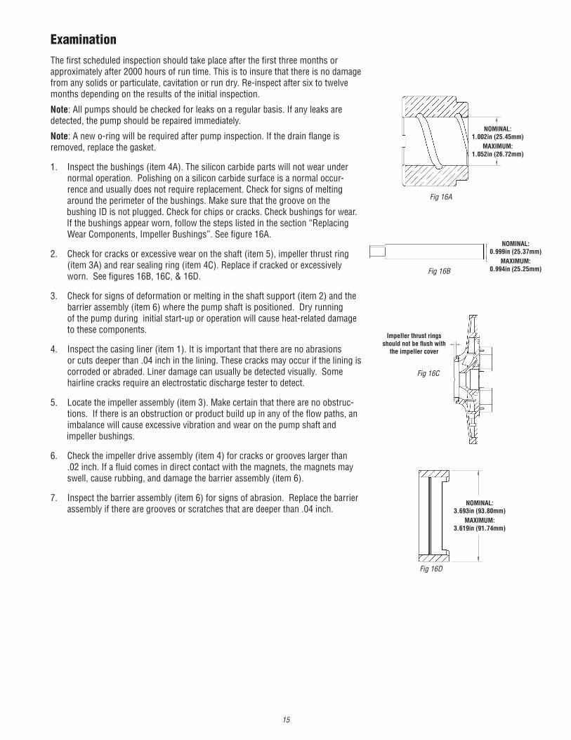
1. Inspect the bushings (item 4A). The silicon carbide parts will not wear under normal operation. Polishing on a silicon carbide surface is a normal occur- rence and usually does not require replacement. Check for signs of melting around the perimeter of the bushings. Make sure that the groove on the bushing ID is not plugged. Check for chips or cracks. Check bushings for wear. If the bushings appear worn, follow the steps listed in the section “Replacing Wear Components, Impeller Bushings”. See figure 16A.
2. Check for cracks or excessive wear on the shaft (item 5), impeller thrust ring (item 3A) and rear sealing ring (item 4C). Replace if cracked or excessively worn. See figures 16B, 16C, & 16D.
3. Check for signs of deformation or melting in the shaft support (item 2) and the barrier assembly (item 6) where the pump shaft is positioned. Dry running of the pump during initial start-up or operation will cause heat-related damage to these components.
4. Inspect the casing liner (item 1). It is important that there are no abrasions or cuts deeper than .04 inch in the lining. These cracks may occur if the lining is corroded or abraded. Liner damage can usually be detected visually. Some hairline cracks require an electrostatic discharge tester to detect.
5. Locate the impeller assembly (item 3). Make certain that there are no obstruc- tions. If there is an obstruction or product build up in any of the flow paths, an imbalance will cause excessive vibration and wear on the pump shaft and impeller bushings.
6. Check the impeller drive assembly (item 4) for cracks or grooves larger than .02 inch. If a fluid comes in direct contact with the magnets, the magnets may swell, cause rubbing, and damage the barrier assembly (item 6).
7. Inspect the barrier assembly (item 6) for signs of abrasion. Replace the barrier assembly if there are grooves or scratches that are deeper than .04 inch.
Fig 16A
Fig 16B
Fig 16C
Fig 16D
NOMINAL:1.002in (25.45mm)
MAXIMUM:1.052in (26.72mm)
Impeller thrust rings should not be flush with
the impeller cover
NOMINAL:3.693in (93.80mm)
MAXIMUM:3.619in (91.74mm)
NOMINAL:0.999in (25.37mm)
MAXIMUM:0.994in (25.25mm)

16
Replacing Wear Components Use the following procedures to replace any wear components that are excessively worn, cracked or broken.
Shaft Support/Front Thrust Washer Removal
1. Remove the casing (item 1) from the base plate and piping.
2. Place the casing in an arbor press with ETFE lining side down. Note: care should be taken to not damage the lining.
3. Place arbor on the nose of the front shaft support (item 2) and carefully press the front shaft support out of casing. See figure 17. Note: Care should be taken to not damage the silicon carbide thrust ring (item 2A). Use something soft to catch the shaft support as it drops from the casing.
Installation of Replacement Support/Front Thrust Washer 1. Place the casing in an arbor press with the suction flange down.
2. If the silicon carbide thrust ring (item 2A) is damaged and needs to be replaced the PTFE o-ring (item 2B) should also be replaced. Remove the thrust ring by hand. Install the new o-ring in the groove and press the new thrust ring into the shaft support being sure to line up the 4 slots in the ring with the four tabs on the shaft support.
3. Position the front shaft support in the bore of the casing suction and align the anti-rotation pins on the front shaft support with the blind slots in the casing.
4. Press evenly on the face of the plastic shaft support with a soft-faced arbor until the front shaft support is fully seated in the bore.
Impeller Thrust Ring The impeller thrust ring is located in the front of the impeller shroud.
Removal
1. The silicon carbide impeller thrust ring (item 3A) must be broken to remove it from the impeller. Be careful not to damage the bore or face of the front impeller shroud. Silicon carbide is brittle and can be broken easily by hitting it with a hammer. Care should be taken during this process to prevent personal injury from flying debris or sharp edges. Wear proper safety clothing.
Note: A new impeller thrust ring with PTFE encapsulated o-ring will be required after removal. Replacement1. Place the impeller and impeller drive assembly (items 2B, 3, 3A, 4, 4A & 4C) on a table with the eye of the impeller facing up.
2. Using petroleum jelly or similar substance, place the o-ring (item 2B) into the groove on the rear of the impeller thrust ring (item 3A). See figure 18.
3. Position the replacement impeller thrust ring in the bore of the front shroud with the snap fit ridge towards the bottom of the bore. See figure 19. Align the two anti-rotation slots on the impeller thrust ring with the two raised bosses of the impeller shroud.
4. Place the impeller and impeller drive assembly in an arbor press. Using a soft faced arbor, gently press the impeller thrust ring into place. Make sure thrust ring is completely seated. See figure 20.
Fig 17
Fig 20
Fig 18
Fig 19

17
Rear Sealing RingThe rear sealing ring (item 4C) is located in the rear bore of the barrier assembly (item 6).
Removal
1. The rear sealing ring fits into the barrier assembly with a snap fit. To remove the existing sealing ring, cut a notch in the ring using a standard razor knife and remove.
Replacement
1. Place the barrier in an arbor press.
2. Place rear sealing ring on the rear bore of the barrier and align anti-rotation tabs on the rear sealing ring with the pockets in thebarrier. See figure 21.
3. Using a soft faced arbor, press in the ring. The sealing ring is fully seated when the bottom face of the ring is in contact with the bottom of the barrier. You can hear and feel the ring snap into place. See figures 22 & 23.
Impeller Assembly Removal and ReplacementThe impeller assembly can be replaced as required to change the impeller diameter or replace damaged or worn parts.
Note: Prior to disassembly determine which impeller and drive hub the pump has. See identification page towards the back of this manual.
A. For two piece impeller and drive hub.
Removal1. Holding the impeller (item 3) and impeller drive assembly (item 4) by hand, place a 3/8- inch diameter rod (or a 3/8” ratchet extension) through the perforations in the bore of the impeller drive assembly. See figure 24.
2. While holding the impeller drive assembly tap on the rod with a hammer in several locations until the impeller assembly separates from the impeller drive assembly.
Replacement
1. Place the impeller drive assembly (item 4) in an arbor press with the kidney shaped slots facing up.
2. Align the kidney-shaped drive pins on the impeller assembly (item 3) with the kidney-shaped slots in the impeller drive assembly and press partially in by hand.
3. Complete installation by pressing the impeller assembly into the impeller drive assembly with an appropriate size arbor (be sure the arbor does not touch the impeller thrust ring (item 3A) use an arbor with a larger diameter than the eye of the impeller) until the back side of impeller rear shroud is flush with front face of impeller drive assembly. See figure 25.
figure 22figure 21 figure 23
figure 24
figure 25

18
UCII Single Piece Impeller & Snap-Fit Drive Disassembly Tool Instructions
P/N: 111085
Removal
1. To remove the impeller from the drive hub to replace bushings or trim an impeller you must use
removal tool (P/N 110855) & a 9/16” socket & ratchet tool. Important Note: Only use hand tools. Air or
power tools will cause damage to the impeller bushings and/or other components. See figure 1 below.
2. From the drive end locate the snap-fit prongs on either side of the bushing. See figure 2 below.
Impeller Bolt Bushing color & material
may vary
The 4 Drive Bolts are in the retracted
position to start.
Fig. 1
Fig. 2
UCII Single Piece Impeller & Snap-Fit Drive Disassembly Tool Instructions
19
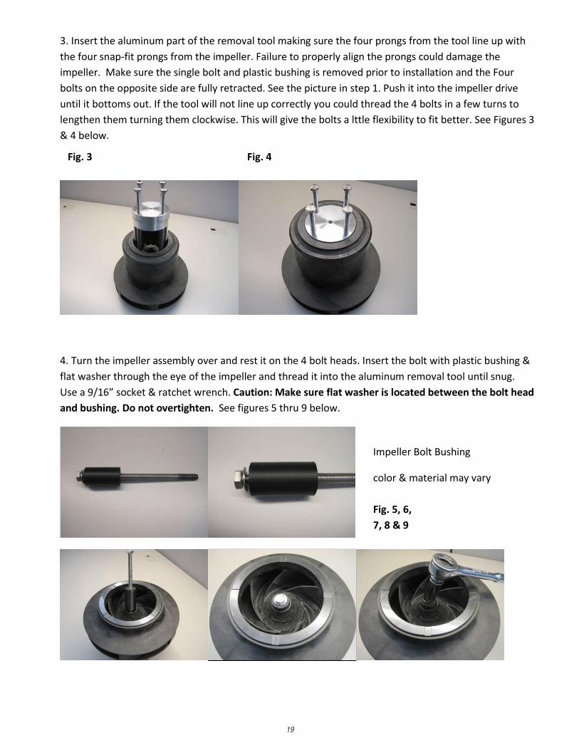
3. Insert the aluminum part of the removal tool making sure the four prongs from the tool line up with
the four snap-fit prongs from the impeller. Failure to properly align the prongs could damage the
impeller. Make sure the single bolt and plastic bushing is removed prior to installation and the Four
bolts on the opposite side are fully retracted. See the picture in step 1. Push it into the impeller drive
until it bottoms out. If the tool will not line up correctly you could thread the 4 bolts in a few turns to
lengthen them turning them clockwise. This will give the bolts a lttle flexibility to fit better. See Figures 3
& 4 below.
4. Turn the impeller assembly over and rest it on the 4 bolt heads. Insert the bolt with plastic bushing &
flat washer through the eye of the impeller and thread it into the aluminum removal tool until snug.
Use a 9/16” socket & ratchet wrench. Caution: Make sure flat washer is located between the bolt head
and bushing. Do not overtighten. See figures 5 thru 9 below.
Impeller Bolt Bushing
color & material may vary
Fig. 3 Fig. 4
Fig. 5, 6,
7, 8 & 9

20
5. Turn the impeller assembly over and rest it on the impeller thrust washer. Suggest using a piece of
cardboard or some other soft material to protect the thrust washer. Start tightening the 4 bolts in a
crisscross pattern evenly. Caution: tools will be attracted to the magnets located inside of the impeller
drive assembly. See figures 10 & 11 below.
6. This will disengage the snap-fit prongs and allow the impeller and drive to separate. This will require
about 1” of separation between the impeller back shroud and the drive before they can be completely
separated. See figures 12 thru 14 below.
Fig. 10 Fig. 11
Fig. 12 Fig. 13 Fig. 14

21
7. Unthread the bolt used for the impeller eye and remove the tool from the drive hub. See figures 15 &
16 below.
8. Pull out the bushing by hand and set it aside. See figure 17 above. Caution: Failure to remove the
bushing at this stage could damage the bushing when it falls out while turning the drive over. See figures
18 & 19 below. Turn the drive over and push on the Plastic outer section of the drive to remove the
impeller removal tool. See figures 20 thru 23 below.
Fig. 15 Fig. 16 Fig. 17
Fig. 18 Fig. 19 Fig. 20
Fig. 21 Fig. 23 Fig. 22
22
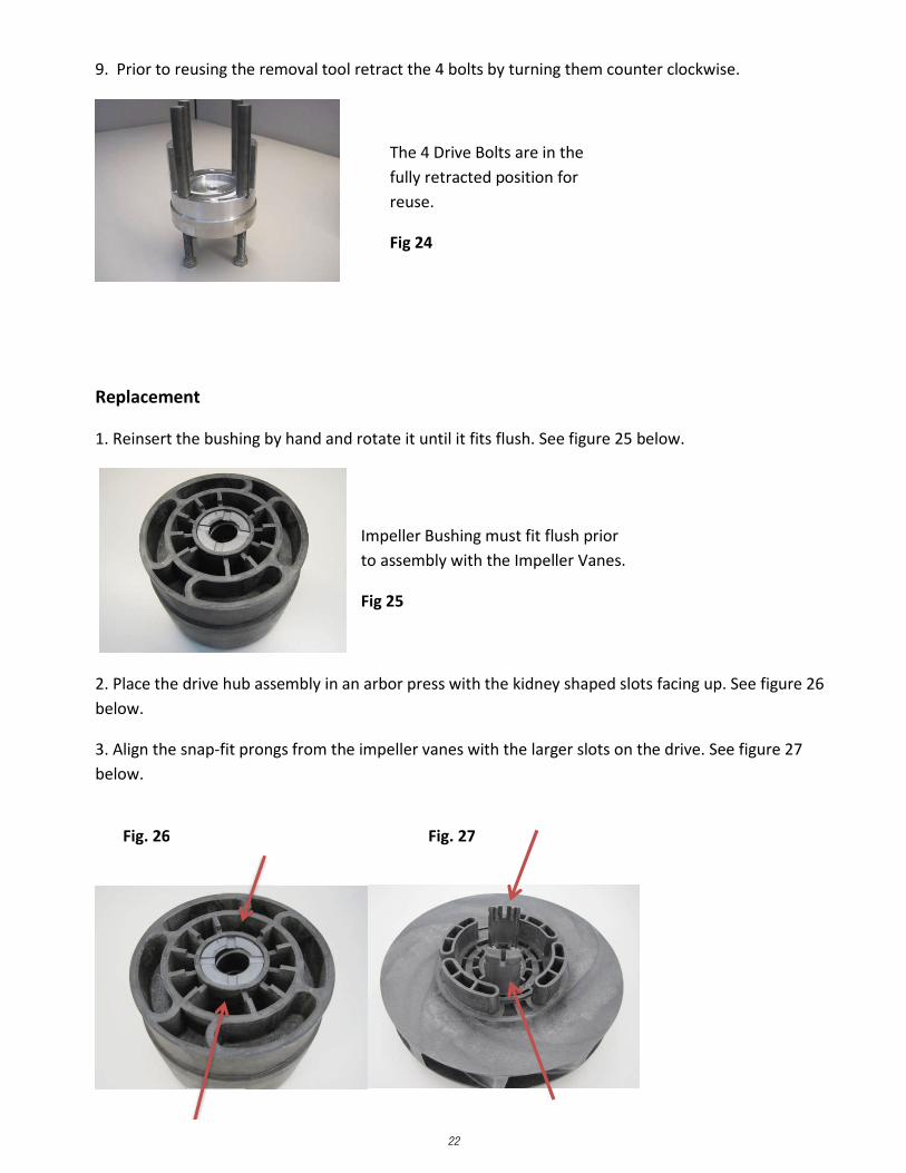
9. Prior to reusing the removal tool retract the 4 bolts by turning them counter clockwise.
Replacement
1. Reinsert the bushing by hand and rotate it until it fits flush. See figure 25 below.
2. Place the drive hub assembly in an arbor press with the kidney shaped slots facing up. See figure 26
below.
3. Align the snap-fit prongs from the impeller vanes with the larger slots on the drive. See figure 27
below.
The 4 Drive Bolts are in the
fully retracted position for
reuse.
Fig 24
Impeller Bushing must fit flush prior
to assembly with the Impeller Vanes.
Fig 25
Fig. 26 Fig. 27
23
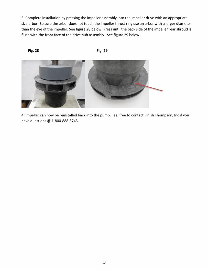
3. Complete installation by pressing the impeller assembly into the impeller drive with an appropriate
size arbor. Be sure the arbor does not touch the impeller thrust ring use an arbor with a larger diameter
than the eye of the impeller. See figure 28 below. Press until the back side of the impeller rear shroud is
flush with the front face of the drive hub assembly. See figure 29 below.
4. Impeller can now be reinstalled back into the pump. Feel free to contact Finish Thompson, Inc if you
have questions @ 1-800-888-3743.
Fig. 28 Fig. 29

24
Power End ReassemblySee section Assembly of Pumps without Motors, steps 1-9 on pages 6-8.
Pump End Reassembly1. Take the pump casing (item 1) and lay it suction side down on a clean flat surface. See figure 27. Note: Care should be taken to not damage the lining.
2. Carefully place the impeller (item 3) and impeller drive assembly (item 4) into the housing onto the thrust ring. See figure 28.
CAUTION: Do not use steel/iron tools near the magnets. These tools are attracted to the strong magnetic force and could damage them upon impact.
3. Install a new o-ring (item 12) in the housing. See figure 29. If removed, reinstall the shaft (item 5) align the four flats on the one end with the flats on the barrier assembly and push in by hand.
4. Slide the barrier and shaft assembly over the impeller assembly and through the bushings. Align the shaft with the front shaft support. Press down on the barrier assembly until it is fully seated. See figure 30.
Impeller Bushings
Removal1. Remove the impeller according to the steps listed in the section Impeller Assembly, Removal.
2. The front bushing (closest to the impeller) should be floating and be able to be removed by hand. For the rear bushing, place the impeller drive assembly on an arbor press with the of the impeller drive facing up
3. Insert a 1-1/4” diameter arbor into the bore of the impeller drive assembly.
4. Press on face of rear impeller bushing until the bushing has been removed. Check both bushings for excessive wear.
5. Check the impeller bore for signs of plastic melting or fretting wear.
Replacement1. Place the impeller drive assembly in an arbor press with the impeller side facing down.
2. Start the rear bushing into bore of impeller while lining up the four flats on the bushing with the flats in the impeller drive. The interrupted face end of the bushing should be facing up. Press the bushing into the impeller bore with a 1-3/4” diameter soft-faced arbor. See figure 26.
3. To install the front bushing, turn the impeller drive over. The interrupted face of the bushing should be facing up. Align the four flats on the bushing with the four flats in the impeller drive. The front bushing will slide easily into place. The face of the bushing should be approximately flush with the top of the impeller drive. Note: Make sure bushing does not fall out & get damaged during reassembly.
4. Reinstall the impeller according to the steps listed in the section Impeller Assembly, Replacement.
figure 26
figure 28 figure 29 figure 30
figure 27

25
5. Make sure the vapor protection o-ring (item 24) is in the clamp ring groove (item 7). Place the rounded edge of the clamp ring over the barrier assembly and position on the rear face of the casing. Note: It is important to properly line up the 8-through holes in the clamp ring to the 8 threaded holes in the casing. See figure 31. The 4 threaded holes in the clamp ring should align per figure 31a.
6. Attach the clamp ring with (8) M16 hex head cap screws and lock washers (items 13 & 13A). Tighten evenly around circumference. Torque the screws to 90 ft-lbs (122 N-m) unlubricated. 7. Lubricate the vapor protection o-ring on the front side of the motor adapter using a compatible lubricant. See figure 32.8. Make sure the (2) jackscrews (item 14) are fully extended. If not turn the (2) jackscrews clockwise until the heads touch the motor adapter.
9. Carefully slide the wet end towards (items 1-7) the motor adapter (item 9) until it touches the jackscrews (there will be some magnetic attraction). See figure 33.
10. Slowly and evenly turn the jackscrews counterclockwise to allow the wet end to slowly slide into the motor adapter. Be careful not the cut the o-ring as the assembly is put together. When the jackscrews are fully retracted, if necessary use the (4) M16 hex head bolts (item 15) to draw the pump end onto the motor adapter.
11. Bolt the wet end to the motor adapter by installing the (4) M16 hex head cap screws & lock washers (items 15 & 15A) and torque evenly to 90 ft-lbs (122 N-m). See figure 34.
figure 31
figure 31a
figure 34
vapor protection o-ringfigure 32
figure 33

26
HELPFUL HINTS
Do not pump liquids containing ferrous metal fines.
If magnets de-couple, stop the pump immediately. The rare earth magnets used in this pump are more resistant to demagnetization, but operating the pump with the magnets de-coupled will eventually weaken the magnets.
A power monitor is strongly recommended. This device will help protect the pump against abnormal operating conditions such as dry running, magnet de-coupling, cavitation, etc.
Power monitors are required and must be used with all ATEX certified pumps.
The setting of the drive magnet dimension is critical. Failure to properly set the dimension may result in de-coupling or damage to pump components.
Do not use mismatched drive magnet assemblies (impeller drive magnet and the outer drive magnet assembly). The drives are marked with either an “A” or “B”. Use only components with the same drive letter designation. A serial number plate is attached to the motor adapter section.
Call our toll free Technical Service Hot Line, 1-800-888-3743, if you have any questions regarding product operation or repair.
ORDERING SPARE PARTS
Spare parts can be ordered from your local distributor. Always refer to the pump model number to avoid error.
OTHER FINISH THOMPSON PUMP PRODUCTS
Drum Transfer Pumps are available in sanitary construction, Stainless steel, polypropylene and CPVC. Flows to 40 gpm, Discharge heads to 300 feet and viscosities to 100,000 cps.
Portable Mixers for turbine mixing and blending handle viscosities to 1,000 cP with gentle, non-vortexing circulation. Available in 316 stainless steel construction.
Centrifugal Pumps in polypropylene, PVDF, stainless steel, or Hastelloy C come with a wide variety of sealing materials. Flows to 330 gpm, discharge heads to 275 feet, and temperatures to 220°F (104°C)
For more information contact Finish Thompson Inc. Call our toll free Technical Service Hot Line, 1-800-888-3743, if you have any questions regarding product operation or repair.
TROUBLESHOOTINGNO OR INSUFFICIENT DISCHARGE• Air leaks in suction piping.• Pump not primed.• Discharge head higher than anticipated.• Closed valve.• Viscosity or specific gravity too high (magnets uncoupled).• Suction lift too high or insufficient NPSH.• Clogged suction line or impeller vanes.• Motor rotation incorrect (correct rotation when viewed from the fan end is clockwise).
INSUFFICIENT PRESSURE• Air or gas in liquid.• Impeller diameter too small.• System head lower than anticipated.• Motors speed insufficient (too low) or motor rotation incorrect (correct rotation when viewed from the fan end is clockwise).
LOSS OF PRIME• Leaking suction line.• Foot valve or suction opening not submerged enough.• Foot valve too small or leaking.• Air or gas in liquid.• Foreign matter in impeller.• Leaking valve. Suction lift too high or insufficient NPSH.
EXCESSIVE POWER CONSUMPTION• Head lower than rating. • Excessive flow.• Specific gravity or viscosity too high.
VIBRATION/NOISE• Loose magnet.• Drive magnet rubbing.• Pump cavitation from improper suction or feed.• Motor or piping not properly secured.• Foreign object in impeller.
CHEMICAL REACTION DISCLAIMER
The user must exercise primary responsibility in selecting the product’s materials of construction, which are compatible with the fluid(s) that come(s) in contact with the product. The user may consult Finish Thompson, Inc. (manufacturer) and a manufacturer’s representative/distributor agent to seek a recommendation of the product’s material of construction that offers the optimum available chemical compatibility.
However neither manufacturer nor agent shall be liable for product damage or failure, injuries, or any other damage or loss arising out of a reaction, interaction or any chemical effect that occurs between the materials of the product’s construction and fluids that come into contact with the product’s internals.
IMPORTANT NOTICEU.S. Export Administration Regulations, pursuant to ECCN 2B350, prohibit the export or reexport to certain enumerated countries of sealless centrifugal pumps in which all wetted ma-terials are constructed from fluoropolymers without first apply-ing for and obtaining a license from the U.S. Bureau of Industry and Security (BIS). This affects all Finish Thompson magnetic-drive pumps constructed from PVDF or lined with ETFE. Please contact the BIS (www.bis.doc.gov) or Finish Thompson with questions regarding the Regulations or a list of the countries to which they apply.

27
UCII EXPLODED VIEW PARTS DIAGRAM

28
UCII Spare PartsItem Qty Description Part Number
1 1
Casing - ETFE-lined, Painted Ductile IronUC2110 - 150# flange 107777-1UC2110 - 300# flange 107777-2UC2110 - ISO PN40 flange 107777-3UC2110L - 150# flange 110364-1UC2110L - 300# flange 110364-2UC2110L - ISO PN40 flange 110364-3UC3110 - 150# flange 108940-1UC3110 - 300# flange 108940-2UC3110 - ISO PN40 flange 108940-3UC3158 - 150# flange 108252-1UC3158 - 300# flange 108252-2UC3158 - ISO PN40 flange 108252-3UC328 - 150# flange 110153-1UC328 - 300# flange 110153-2UC328 - ISO PN40 flange 110153-3UC3210 - 150# flange 110405-1UC3210 - 300# flange 110405-2UC3210 - ISO PN40 flange 110405-3UC4310H - 150# flange 108982-1UC4310H - 300# flange 108982-2UC4310H - ISO PN40 flange 108982-3UC438 - 150# flange 108251-1UC438 - 300# flange 108251-2UC438 - ISO PN40 flange 108251-3UC436 - 150# flange 111358-1UC436 - 300# flange 111358-2UC436 - ISO PN40 flange 111358-3UC6410 - 150# flange 108989-1UC6410 - 300# flange 108989-2UC6410 - ISO PN40 flange 108989-3
2 1
Front Shaft Support Only (2A Sold Separately)UC2110, 2110L, 3110 107765UC3158, 328, 3210, 436, 438 107666UC4310H 108976UC6410 110097
2A 1
Front Thrust Ring Only - Silicon CarbideUC2110, 2110L, 3110 107989UC3158, 328, 3210, 436, 438 107736UC4310H 108977UC6410 110098
2B 2
O-Ring - PTFE EncapsulatedUC2110, 2110L, 3110 N/AUC3158, 328, 3210, 436, 438 (UC3210 only uses O-ring for the shaft support) 108571UC4310H 110140UC6410 110143
3 1Impeller Assembly
With thrust ring & PTFE Encapsulated O-ring See charts on pg. 34-36
3A 1
Impeller Thrust Ring - Silicon CarbideUC2110, 2110L, 3110 107990UC3158, 328, 436, 438 107737UC3210 110966UC4310H 108978UC6410 110099
29
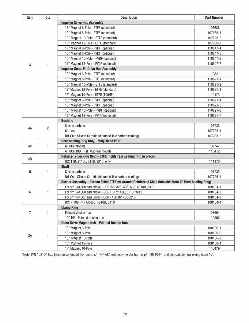
Item Qty Description Part Number
4 1
Impeller Drive Hub Assembly"B" Magnet 6-Pole - ETFE (standard) 107688"C" Magnet 8-Pole - ETFE (standard) 107688-1"D" Magnet 10-Pole - ETFE (standard) 107688-2"E" Magnet 12-Pole - ETFE (standard) 107688-3"B" Magnet 6-Pole - PVDF (optional) 110647-4"C" Magnet 8-Pole - PVDF (optional) 110647-5"D" Magnet 10-Pole - PVDF (optional) 110647-6"E" Magnet 12-Pole - PVDF (optional) 110647-7
Impeller Snap-Fit Drive Hub Assembly"B" Magnet 6-Pole - ETFE (standard) 110821"C" Magnet 8-Pole - ETFE (standard) 110821-1
"D" Magnet 10-Pole - ETFE (standard) 110821-2“E” Magnet 12-Pole - ETFE (standard) 110821-3"F" Magnet 10-Pole - ETFE (100HP) 110475
"B" Magnet 6-Pole - PVDF (optional) 110821-4"C" Magnet 8-Pole - PVDF (optional) 110821-5"D" Magnet 10-Pole - PVDF (optional) 110821-6"E" Magnet 12-Pole - PVDF (optional) 110821-7
4A 2
Bushing Silicon carbide 107738Carbon 107738-1Dri-Coat Silicon Carbide (diamond-like carbon coating) 107738-2
4C 1Rear Sealing Ring Only - Moly-filled PTFE
All UCII models 107747All UCII 100 HP (F Magnet) models 110472
4D 1Retainer + Locking Ring - ETFE (holds rear sealing ring in place)
UC2110, 2110L, 3110, 3210, only 111470
5 1Shaft
Silicon carbide 107735Dri-Coat Silicon Carbide (diamond-like carbon coating) 107735-1
6 1
Barrier Assembly - Carbon Filled ETFE w/ Aramid Reinforced Shell (includes item 4C Rear Sealing Ring)For s/n 144368 and above - UC3158, 328, 436, 438, 4310H, 6410 108104-1For s/n 144368 and above - UC2110, 2110L, 3110, 3210 108104-2For s/n 144367 and under - UCII - 100 HP - UC3210 108104-3UCII - 100 HP - UC438, 4310H, 6410 108104-4
7 1Clamp Ring
Painted ductile iron 108664100 HP - Painted ductile iron 110866
8A 1
Outer Drive Magnet Hub - Painted Ductile Iron"B" Magnet 6-Pole 108106-1"C" Magnet 8-Pole 108106-2"D" Magnet 10-Pole 108106-3"E" Magnet 12-Pole 108106-4“F” Magnet 10-Pole 110479
*Note: P/N 108104 has been discontinued. For pump s/n 144367 and below, order barrier p/n 108104-1 and compatible new o-ring (item 12).
30
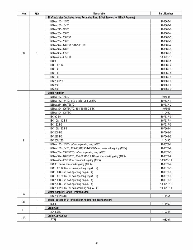
Item Qty Description Part Number
8B 1
Shaft Adapter (includes items Retaining Ring & Set Screws for NEMA Frames)NEMA 143-145TC 108665-1NEMA 182-184TC 108665-2NEMA 213-215TC 108665-3NEMA 254-256TC 108665-4NEMA 284-286TSC 108665-5NEMA 284-286TC 108665-6NEMA 324-326TSC, 364-365TSC 108665-7NEMA 324-326TC 108665-8NEMA 364-365TC 108665-9NEMA 404-405TSC 108665-10IEC 90 108666-1IEC 100/112 108666-2IEC 132 108666-3IEC 160 108666-4IEC 180 108666-5IEC 200/225 108666-6IEC 250 108666-8IEC 280 108666-9
9 1
Motor AdapterNEMA 143-145TC 107637NEMA 182-184TC, 213-215TC, 254-256TC 107637-1NEMA 284-286/TSCTC 107637-2NEMA 324-326TSC/TC, 364-365TSC & TC 107663NEMA 404-405TSC 110490IEC 90 B5 107637-3IEC 100/112 B5 107637-4IEC 132 B5 107637-5IEC 160/180 B5 107663-1IEC 200 B5 107663-2IEC 225 B5 107663-3IEC 250/280 110490NEMA 143-145TC- w/ non-sparking ring (ATEX) 108673-1NEMA 182-184TC, 213-215TC, 254-256TC- w/ non-sparking ring (ATEX) 108673-2NEMA 284-286TSC/TC- w/ non-sparking ring (ATEX) 108673-3NEMA 324-326TSC/TC, 364-365TSC & TC- w/ non-sparking ring (ATEX) 108673-7NEMA 404-405TSC w/ non-sparking ring (ATEX) 108673-11IEC 90 B5- w/ non-sparking ring (ATEX) 108673-4IEC 100/112 B5- w/ non-sparking ring (ATEX) 108673-5IEC 132 B5- w/ non-sparking ring (ATEX) 108673-6IEC 160/180 B5- w/ non-sparking ring (ATEX) 108673-8IEC 200 B5- w/ non-sparking ring (ATEX) 108673-9IEC 225 B5- w/ non-sparking ring (ATEX) 108673-10IEC 250/280 B5- w/ non sparkling ring (ATEX) 108673-11
9A 1Motor Adapter Flange - Painted Steel
IEC 250/280/B5 111454
9B 1Vapor Protection O-Ring (Motor Adapter Flange to Motor)
Buna 111462
11 1Drain Cap
304 SSTL 110254
11A 1Drain Cap Gasket
PTFE 108294
31
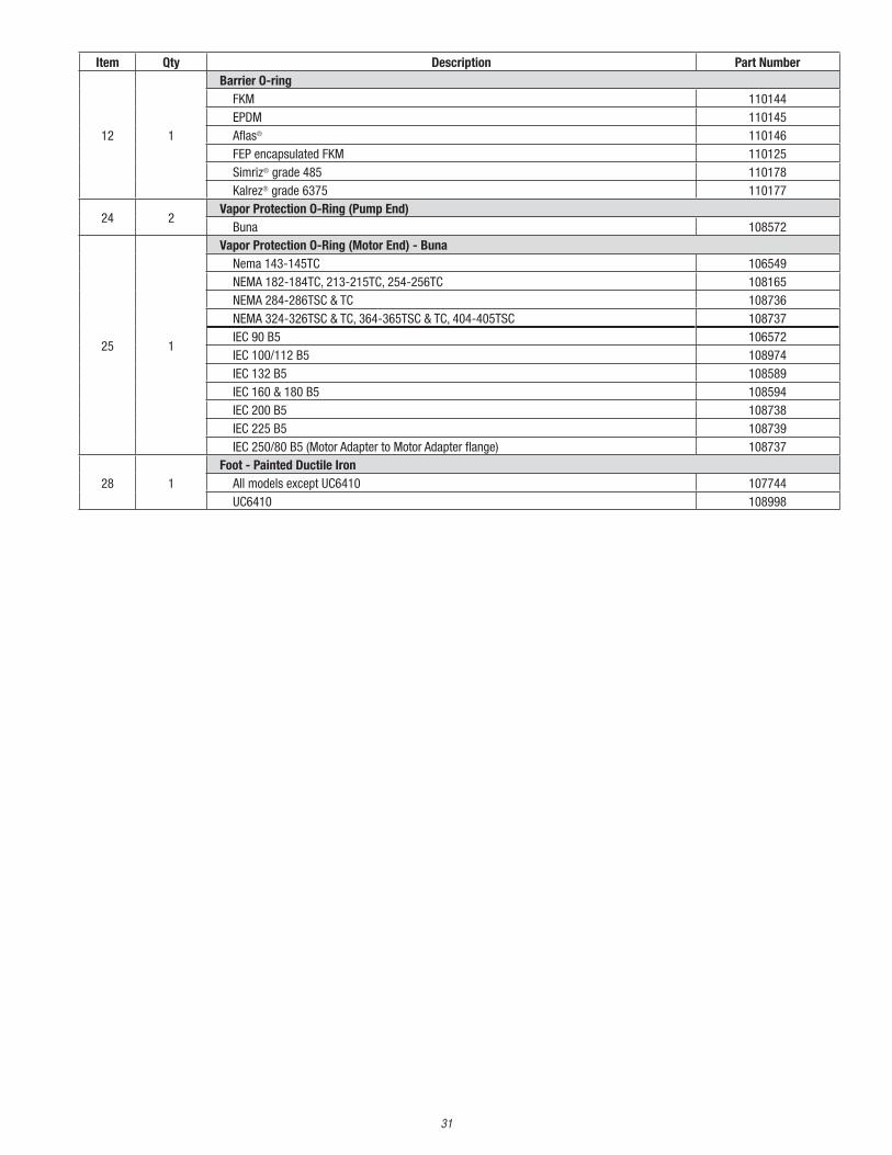
Item Qty Description Part Number
12 1
Barrier O-ringFKM 110144EPDM 110145Aflas® 110146FEP encapsulated FKM 110125Simriz® grade 485 110178Kalrez® grade 6375 110177
24 2Vapor Protection O-Ring (Pump End)
Buna 108572
25 1
Vapor Protection O-Ring (Motor End) - BunaNema 143-145TC 106549NEMA 182-184TC, 213-215TC, 254-256TC 108165NEMA 284-286TSC & TC 108736NEMA 324-326TSC & TC, 364-365TSC & TC, 404-405TSC 108737IEC 90 B5 106572IEC 100/112 B5 108974IEC 132 B5 108589IEC 160 & 180 B5 108594IEC 200 B5 108738IEC 225 B5 108739IEC 250/80 B5 (Motor Adapter to Motor Adapter flange) 108737
28 1Foot - Painted Ductile Iron
All models except UC6410 107744UC6410 108998

32
15A 4Motor Adapter Lock Washers - Stainless Steel
M16 107924
16 4
Motor Bolts - Stainless SteelNEMA 143-145TC, 3/8-16 x 1-1/2" J103207NEMA 182-184, 213-215, 254-256, 284-286TSC or TC- 1/2-13 x 1-1/2" J101858NEMA 324-326, 364-365TSC, 404-405TSC or TC- 5/8-11 x 1-1/2" J100776IEC 90 B5 - M10-1.5 x 30mm 105757IEC 100/112/132 B5 - M12-1.75 x 35mm 105337IEC 160/180/200/225 B5 - M16-2.0 x 45mm 108675IEC 250/280, 5/8-11x2” 111463
16A 4
Motor Lock Washers - Stainless SteelNEMA 143-145TC, 3/8" J100115NEMA 182-184, 213-215, 254-256, 284-286TSC or TC- 1/2" J101023NEMA 324-326, 364-365TSC or TC- 5/8" J104026IEC 90 B5 - M10 108774IEC 100/112/132 B5- M12 106503IEC 160/180/200/225 B5 - M16 107924IEC 250/280, 5/8 J104026
17 1
Retaining RingNEMA 143-145TC, DHT-22 105709NEMA 182-184TC, DHT-28 105710NEMA 213-215TC, DHT-35 106454NEMA 254-256TC, DHT-42 106718NEMA 284-286TSC, DHT-42 106718NEMA 284-286TC, DHO-48 108667NEMA 324-326, 364-365TSC, DHO-48 108667NEMA 324-326TC, 404-405TSC, DHO-55 108668NEMA 364-365TC, DHO-60 108669IEC 90, DHT-24 105712IEC 100/112, DHT-28 105710IEC 132, DHT-38 106468IEC 160, DHT-42 106718IEC 180, DHO-48 108667IEC 200/225, DHO-55 108668IEC 250, DHO-60 108669IEC 280, DHO-65 111459
HardwareItem Qty Description Part Number
11B 2Drain Cap Hex Head Bolts - Stainless Steel
M12-1.75 x 30mm 106507
11C 2Drain Cap Lock Washer - Stainless Steel
M12 106503
13 8Casing Hex Head Cap Screw - Stainless Steel
M16-2 X 45mm 108675
13A 8Casing Lock Washers - Stainless Steel
M16 107924
14 2Jack Bolt - Stainless Steel
M16-2.0 x 80 mm 107102
15 4Motor Adapter Bolts - Stainless Steel
M16-2 X 45mm 108675

33
*Item not shown
Item Qty Description Part Number
18 1
Shaft Adapter Washer (IEC Only)IEC 90 FR 108383IEC 100 FR 108383-1IEC 132 FR 108383-2IEC 160 FR 108383-3IEC 180 FR 108383-4IEC 200/225 FR 108383-5IEC 250 FR 108383-7IEC 280 FR 108383-8
19 1
Shaft Adapter Lock Washer - Stainless Steel (IEC Only)IEC 90- 5/16 J102282IEC 100/112- M10 105757IEC 132- M12 106503IEC 160/180- M16 107924IEC 200/225/250/280- M20 108691
20 1
Shaft Adapter Bolt - Stainless Steel (IEC Only)IEC 90- M8-1.25 x 35 mm J103662IEC 100/112- M10-1.5 x 30mm 105774IEC 132- M12-1.75 x 30mm 106507IEC 160/180- M16-2 x 35mm 108270IEC 200/225- M20-2.5 x 35mm 108690IEC 250/280- M20-2.5 x 40mm 111460
21 2Drive Nut - Stainless Steel
M8 Hex Nut J103930
22 4Drive Lock Washers - Stainless Steel
5/16" J102282
23 2Drive Bolt - Stainless Steel
M8-1.25 x 25mm J103662
27 2Shaft Adapter Set Screw - Stainless Steel
3/8-16 x 3/8 Knurled Cup Point 110112
29 2Foot Bolt - Stainless Steel
M12-1.75 x 30mm 106507
29A 2Foot Lock Washer - Stainless Steel
M12 106503
* 8Motor Adapter Flange Bolts - Stainless Steel
IEC 250/280- B5, M16-2 x 55mm 106507
* 8Motor Adapter Flange Lock Washers
IEC 250/280- B5, M16 106507
* 1Outer Drive Protection Tube
Cardboard tube (for assembly use only) 108958-2
* 1Tools
Impeller Removal Kit - Single Piece Impeller 110855

34
UC Group II Impeller & Impeller Drive Hub Identification
Single piece Impeller Two Piece Impeller w/ weld pins
Single piece Impeller w/snap-fit prongs Two Piece Impeller
Single piece Impeller drive hub w/snap-fit prongs Two Piece Impeller drive hub
35
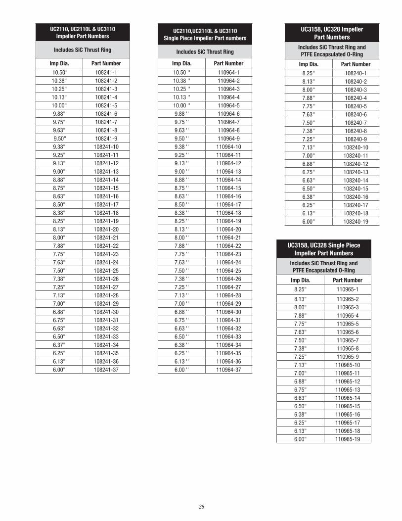
UC3158, UC328 Impeller Part Numbers
Includes SiC Thrust Ring and PTFE Encapsulated O-Ring
Imp Dia. Part Number
8.25" 108240-18.13" 108240-28.00" 108240-37.88" 108240-47.75" 108240-57.63" 108240-67.50" 108240-77.38" 108240-87.25" 108240-97.13" 108240-107.00" 108240-116.88" 108240-126.75" 108240-136.63" 108240-146.50" 108240-156.38" 108240-166.25" 108240-176.13" 108240-186.00" 108240-19
UC2110, UC2110L & UC3110 Impeller Part Numbers
Includes SiC Thrust Ring
Imp Dia. Part Number
10.50" 108241-110.38" 108241-210.25" 108241-310.13" 108241-410.00" 108241-59.88" 108241-69.75" 108241-79.63" 108241-8 9.50" 108241-99.38" 108241-109.25" 108241-119.13" 108241-129.00" 108241-138.88" 108241-148.75" 108241-158.63" 108241-168.50" 108241-178.38" 108241-188.25" 108241-198.13" 108241-208.00" 108241-217.88" 108241-227.75" 108241-237.63" 108241-247.50" 108241-257.38" 108241-267.25" 108241-277.13" 108241-287.00" 108241-296.88" 108241-306.75" 108241-316.63" 108241-326.50" 108241-336.37" 108241-346.25" 108241-356.13" 108241-366.00" 108241-37
UC2110,UC2110L & UC3110 Single Piece Impeller Part numbers
Includes SiC Thrust Ring
Imp Dia. Part Number
10.50 '' 110964-110.38 '' 110964-210.25 '' 110964-310.13 '' 110964-410.00 '' 110964-59.88 '' 110964-69.75 '' 110964-79.63 '' 110964-89.50 '' 110964-99.38 '' 110964-109.25 '' 110964-119.13 '' 110964-129.00 '' 110964-138.88 '' 110964-148.75 '' 110964-158.63 '' 110964-168.50 '' 110964-178.38 '' 110964-188.25 '' 110964-198.13 '' 110964-208.00 '' 110964-217.88 '' 110964-227.75 '' 110964-237.63 '' 110964-247.50 '' 110964-257.38 '' 110964-267.25 '' 110964-277.13 '' 110964-287.00 '' 110964-296.88 '' 110964-306.75 '' 110964-316.63 '' 110964-326.50 '' 110964-336.38 '' 110964-346.25 '' 110964-356.13 '' 110964-366.00 '' 110964-37
UC3158, UC328 Single Piece Impeller Part Numbers
Includes SiC Thrust Ring and PTFE Encapsulated O-Ring
Imp Dia. Part Number
8.25" 110965-1
8.13" 110965-28.00" 110965-37.88" 110965-47.75" 110965-57.63" 110965-67.50" 110965-77.38" 110965-87.25" 110965-97.13" 110965-107.00" 110965-116.88" 110965-126.75" 110965-136.63" 110965-146.50" 110965-156.38" 110965-166.25" 110965-176.13" 110965-186.00" 110965-19

36
UC3210 Impeller Part Numbers
Includes SiC Thrust Ring
Imp Dia. Part Number
10.50" 11042310.38" 110423-110.25" 110423-210.13" 110423-310.00" 110423-49.88" 110423-59.75" 110423-69.63" 110423-7 9.50" 110423-89.38" 110423-99.25" 110423-109.13" 110423-119.00" 110423-128.88" 110423-138.75" 110423-148.63" 110423-158.50" 110423-168.38" 110423-178.25" 110423-188.13" 110423-198.00" 110423-207.88" 110423-217.75" 110423-227.63" 110423-237.50" 110423-247.38" 110423-257.25" 110423-267.13" 110423-277.00" 110423-286.88" 110423-296.75" 110423-306.63" 110423-316.50" 110423-326.37" 110423-336.25" 110423-346.13" 110423-356.00" 110423-36
Aflas® is a trademark of the Asahi Glass Co., Ltd.Kalrez® is a registered trademark of DuPont Performance Elastomers.Simriz® Perfluoroelastomer is a registered trademark of Simrit® division of Freudenberg-NOK.
UC3210 Single Piece Impeller Part Numbers
Includes SiC Thrust Ring
Imp Dia. Part Number
10.50 '' 110963-110.38 '' 110963-210.25 '' 110963-310.13 '' 110963-410.00 '' 110963-59.88 '' 110963-69.75 '' 110963-79.63 '' 110963-89.50 '' 110963-99.38 '' 110963-109.25 '' 110963-119.13 '' 110963-129.00 '' 110963-138.88 '' 110963-148.75 '' 110963-158.63 '' 110963-168.50 '' 110963-178.38 '' 110963-188.25 '' 110963-198.13 '' 110963-208.00 '' 110963-217.88 '' 110963-227.75 '' 110963-237.63 '' 110963-247.50 '' 110963-257.38 '' 110963-267.25 '' 110963-277.13 '' 110963-287.00 '' 110963-296.88 '' 110963-306.75 '' 110963-31
6.63 '' 110963-326.50 '' 110963-33
UC436 Single Piece Impeller Part Numbers
Includes SiC Thrust Ring and PTFE Encapsulated O-Ring
Imp Dia. Part Number
6.50" 110962-156.38" 110962-166.25" 110962-176.13" 110962-186.00" 110962-195.81" 110962-205.45" 110962-21
UC436 Impeller Part Numbers
Includes SiC Thrust Ring and PTFE Encapsulated O-Ring
Imp Dia. Part Number
6.50" 108239-156.38" 108239-166.25" 108239-176.13" 108239-186.00" 108239-195.81" 108242-15.45" 108242-2

Part Number 108725 Rev17, 4/13/2021
UC438 Impeller Part Numbers
Includes SiC Thrust Ring and PTFE Encapsulated O-Ring
Imp Dia. Part Number
8.25" 108239-18.13" 108239-28.00" 108239-37.88" 108239-47.75" 108239-57.63" 108239-67.50" 108239-77.38" 108239-87.25" 108239-97.13" 108239-107.00" 108239-116.88" 108239-126.75" 108239-136.63" 108239-146.50" 108239-156.38" 108239-166.25" 108239-176.13" 108239-186.00" 108239-19
UC438 Single Piece Impeller Part Numbers
Includes SiC Thrust Ring and PTFE Encapsulated O-Ring
Imp Dia. Part Number
8.25 '' 110962-18.13 '' 110962-28.00 '' 110962-37.88 '' 110962-47.75 '' 110962-57.63 '' 110962-67.50 '' 110962-77.38 '' 110962-87.25 '' 110962-97.13 '' 110962-107.00 '' 110962-116.88 '' 110962-126.75 '' 110962-136.63 '' 110962-146.50 '' 110962-156.38 '' 110962-166.25 '' 110962-176.13 '' 110962-186.00 '' 110962-19
UC6410 Single Piece Impeller Part Numbers
Includes SiC Thrust Ring and PTFE Encapsulated O-Ring
Imp Dia. Part Number
10.50 '' 110867-110.38 '' 110867-210.25 '' 110867-310.13 '' 110867-410.00 '' 110867-59.88 '' 110867-69.75 '' 110867-79.63 '' 110867-89.50 '' 110867-99.38 '' 110867-109.25 '' 110867-119.13 '' 110867-129.00 '' 110867-138.88 '' 110867-148.75 '' 110867-158.63 '' 110867-168.50 '' 110867-178.38 '' 110867-188.25 '' 110867-198.13 '' 110867-208.00 '' 110867-21
UC4310H Single Piece Impeller Part Numbers
Includes SiC Thrust Ring and PTFE Encapsulated O-Ring
Imp Dia. Part Number
10.50 '' 110875-110.38 '' 110875-210.25 '' 110875-310.13 '' 110875-410.00 '' 110875-59.88 '' 110875-69.75 '' 110875-79.63 '' 110875-89.50 '' 110875-99.38 '' 110875-109.25 '' 110875-119.13 '' 110875-129.00 '' 110875-138.88 '' 110875-148.75 '' 110875-158.63 '' 110875-168.50 '' 110875-178.38 '' 110875-188.25 '' 110875-198.13 '' 110875-208.00 '' 110875-21


![INDEX [] and Machinery... · ansi standard 1792–1816 ... ansi b4.2 642, 644, 646, 648–655, 657. index 2559 ansi b4.4m 656 ansi b47.1 1882 ansi b5.18 920, 922–924 ansi b6. 7](https://static.fdocuments.us/doc/165x107/5aa7faa47f8b9aee748cbd3f/index-and-machineryansi-standard-17921816-ansi-b42-642-644-646.jpg)