Anschutz Std20plus Op Manual
46
Raytheon Marine GmbH High Seas Products Postfach 1166 D – 24100 Kiel Germany Tel +49–4 31–30 19–0 Fax +49–4 31–30 19–291 Email [email protected] www.raymarine.com R 3125E.DOC012 Edition: 31. Jan. 2000 Gyro Compass Equipment STANDARD 20 PLUS consisting of: – Gyro Compass STANDARD 20, Type 110 – 800 – Control Unit, Type GY01 – U01 or Type GY03 – U01 with Autopilot Operation – Operator Unit STANDARD 20, Type 130 – 601 E01 OPERATOR MANUAL
-
Upload
constantinos-peppas -
Category
Documents
-
view
1.225 -
download
17
Transcript of Anschutz Std20plus Op Manual

Raytheon Marine GmbHHigh Seas ProductsPostfach 1166D – 24100 KielGermanyTel +49–4 31–30 19–0Fax +49–4 31–30 19–291Email [email protected]
R
3125E.DOC012 Edition: 31. Jan. 2000
Gyro Compass EquipmentSTANDARD 20 PLUS
consisting of:
– Gyro Compass STANDARD 20, Type 110 – 800
– Control Unit, Type GY01 – U01 orType GY03 – U01 with Autopilot Operation
– Operator Unit STANDARD 20, Type 130 – 601 E01
OPERATOR MANUAL

Weitergabe sowie Vervielfältigung dieser Unterlage, Verwertung undMitteilung ihres Inhaltes nicht gestattet, soweit nicht ausdrücklichzugestanden. Zuwiderhandlungen verpflichten zu Schadenersatz.
Copying of this document, and giving it to others and the use orcommunication of the contents thereof, are forbidden without expressauthority. Offenders are liable to the payment of damages.
Toute communication ou reproduction de ce document, touteexploitation ou communication de son contenu sont interdites, saufautorisation expresse. Tout manquement à cette règle est illicite etexpose son auteur au versement de dommages et intérêts.
Sin nuestra expresa autorización, queda terminantemente prohibida lareproducción total o parcial de este documento, así como su usoindebido y/o su exhibición o comunicación a terceros. De los infractoresse exigirá el correspondiente resarcimiento de daños y perjuicios.

GYROGyro Compass Equipment STANDARD 20 PLUSOperator Manual
COMPASSEQUIPMENT
I 3125E.DOC012Edition: 31. Jan. 2000
CONTENTS Page
Safety Regulations
Declaration of Conformity acc to RC Directive 96/98/EC
1 General 1. . . . . . . . . . . . . . . . . . . . . . . . . . . . . . . . . . . . . . . . . . . . . . . . . . . . . . . . . . . . . . .
1.1 Function of the Devices belonging to the Equipment 3. . . . . . . . . . . . . . . . . . . . . . . . .
2 General to the Operating Instruction 4. . . . . . . . . . . . . . . . . . . . . . . . . . . . . . . . . . . . . . .
3 Notes on the Operating Instructions 5. . . . . . . . . . . . . . . . . . . . . . . . . . . . . . . . . . . . . . .
3.1 Multiple Allocation of Keys 6. . . . . . . . . . . . . . . . . . . . . . . . . . . . . . . . . . . . . . . . . . . . . . .
4 Switching–on and off 7. . . . . . . . . . . . . . . . . . . . . . . . . . . . . . . . . . . . . . . . . . . . . . . . . . . .
4.1 Switching–on 7. . . . . . . . . . . . . . . . . . . . . . . . . . . . . . . . . . . . . . . . . . . . . . . . . . . . . . . . . . .
4.2 Switching–off 8. . . . . . . . . . . . . . . . . . . . . . . . . . . . . . . . . . . . . . . . . . . . . . . . . . . . . . . . . . .
5 Measures to be Taken before Commencing a Voyage and during the Voyage 9. . .
6 Gyro Compass Operation 10. . . . . . . . . . . . . . . . . . . . . . . . . . . . . . . . . . . . . . . . . . . . . . . .
6.1 Putting into Operation 11. . . . . . . . . . . . . . . . . . . . . . . . . . . . . . . . . . . . . . . . . . . . . . . . . . .
6.1.1 Possibility of Calling up the Momentary Supporting Liquid Temperature 14. . . . . . . .
6.1.2 Possibility of Calling up the Previous Settling Time 15. . . . . . . . . . . . . . . . . . . . . . . . . .
6.1.3 Possibility of Switching–over to Gyro Compass 2 15. . . . . . . . . . . . . . . . . . . . . . . . . . .
6.2 Operating Instructions with Normal Operation 16. . . . . . . . . . . . . . . . . . . . . . . . . . . . . .
6.2.1 Switching–over from Automatic to Manual Reference Value Input
for the Speed–error Correction 16. . . . . . . . . . . . . . . . . . . . . . . . . . . . . . . . . . . . . . . . . . .
6.2.1.1 Reference Value for Latitude (Lat.) 16. . . . . . . . . . . . . . . . . . . . . . . . . . . . . . . . . . . . . . . .
6.2.1.2 Reference Value for Speed (Spd.) 17. . . . . . . . . . . . . . . . . . . . . . . . . . . . . . . . . . . . . . . .
6.2.2 Switching–over from Manual to Automatic Reference Value Input
for the Speed–error Correction 19. . . . . . . . . . . . . . . . . . . . . . . . . . . . . . . . . . . . . . . . . . .
6.2.2.1 Reference Value for Latitude (Lat.) 19. . . . . . . . . . . . . . . . . . . . . . . . . . . . . . . . . . . . . . . .
6.2.2.2 Reference Value for Speed (Spd.) 20. . . . . . . . . . . . . . . . . . . . . . . . . . . . . . . . . . . . . . . .
6.2.3 Switching from Manual Reference Value Input for the Speed Error Correction to
Input via the Overriding Navigation system (Option) 22. . . . . . . . . . . . . . . . . . . . . . . . .
6.2.3.1 Reference Value for Latitude (Lat.) 22. . . . . . . . . . . . . . . . . . . . . . . . . . . . . . . . . . . . . . . .
6.2.3.2 Reference Value for Speed (Spd.) 23. . . . . . . . . . . . . . . . . . . . . . . . . . . . . . . . . . . . . . . .

Gyro Compass Equipment STANDARD 20 PLUSOperator Manual
II3125E.DOC012 Edition: 31. Jan. 2000
6.3 Additional Operations in Normal Mode 24. . . . . . . . . . . . . . . . . . . . . . . . . . . . . . . . . . . . .
6.3.1 Calling up the Uncorrected Heading Value 24. . . . . . . . . . . . . . . . . . . . . . . . . . . . . . . . .
6.3.2 Calling up the Current Reference Values (Lat. und Spd.) 24. . . . . . . . . . . . . . . . . . . .
6.3.3 Dimming 25. . . . . . . . . . . . . . . . . . . . . . . . . . . . . . . . . . . . . . . . . . . . . . . . . . . . . . . . . . . . . . .
6.3.4 Contrast Adjustment of the LCD Display 25. . . . . . . . . . . . . . . . . . . . . . . . . . . . . . . . . . .
6.3.5 Test 25. . . . . . . . . . . . . . . . . . . . . . . . . . . . . . . . . . . . . . . . . . . . . . . . . . . . . . . . . . . . . . . . . . .
6.4 Emergenca Operation 26. . . . . . . . . . . . . . . . . . . . . . . . . . . . . . . . . . . . . . . . . . . . . . . . . . .
6.5 Warnings by Events at the Gyro Compass 28. . . . . . . . . . . . . . . . . . . . . . . . . . . . . . . . .
7 Fault Operation 29. . . . . . . . . . . . . . . . . . . . . . . . . . . . . . . . . . . . . . . . . . . . . . . . . . . . . . . . .
7.1 Survey of Alarms on the Components of the Equipment 29. . . . . . . . . . . . . . . . . . . . . .
7.2 Procedure in Case an Alarm occurs 30. . . . . . . . . . . . . . . . . . . . . . . . . . . . . . . . . . . . . . .
7.2.1 Survey of Alarms 31. . . . . . . . . . . . . . . . . . . . . . . . . . . . . . . . . . . . . . . . . . . . . . . . . . . . . . .
7.2.2 Fault List 34. . . . . . . . . . . . . . . . . . . . . . . . . . . . . . . . . . . . . . . . . . . . . . . . . . . . . . . . . . . . . .
Annex Operating and Indicating Elements I – II

GYROGyro Compass Equipment STANDARD 20 PLUSOperator Manual
COMPASSEQUIPMENT
III 3125E.DOC012Edition: 31. Jan. 2000
Safety Regulations:
Emergency Operation of the Gyro Compass equipment
Caution!
No speed–error correction is carried out in emergency opera-
tion!
Automatic Reference Value Input:
• For an optimal speed–error correction the reference values of the sensors must becorrect.Before switching–over to automatic reference value input operating mode, the sensorvalues must therefore be checked.
• If the equipment is configured to the overriding naviga-tion system (Sys ), then the automatic reference valueinput (Aut ) is usually without function. When the Lat. key is pressed, in the display appears:
When the Speed key is pressed, in the display appears:
Aut Lat.:00 ° 00’Not connected
Aut Spd:+00.0ktsNot connected
Manual Reference Value Input:
• For an optimal speed–error correction, the reference values must continually beadapted to the current situation.
If there are no compulsive reasons for a manual reference value input (e.g. break-down in sensor/sensor not available), then automatic reference value input must al-ways be selected.When switching–over from automatic to manual reference value input, a head-ing displacement may occur on the heading receivers connected. Thereforecheck, whether a new set heading must be entered to the autopilot (exceptionAutopilot Version NP 2000)!

Gyro Compass Equipment STANDARD 20 PLUSOperator Manual
IV3125E.DOC012 Edition: 31. Jan. 2000

Gyro Compass Equipment STANDARD 20 PLUSOperator Manual
GYROCOMPASSEQUIPMENT
Edition: 11. Nov. 1998 3125E.DOC0121
1 GeneralThe gyro compass equipment STANDARD 20 PLUS is used for navigation on board ships.The gyro compass STANDARD 20 as a sensor (single or twin equipment) ascertains truenorth independently from the earth’s magnetic field and, thus, permits steering of a head-ing referred to geographical north. The heading signal from the absolute, digital positionpick–off in the gyro compass STANDARD 20 undergoes an internal digital processing.The heading value is necessarily corrected in the system. All values required for thecorrection (speed and latitude) are automatically or manually entered.By incorporated transmission systems, the heading is transmitted to repeater compassesand other reference receivers.Option: Autopilot operation HEADING / TRACK CONTROL is possible with the operatorunit NP 2010 or NP 2020 and with external follow–up steering control.
AutopilotNP 2000(optional)
Control Unit
Gyro compassSTANDARD 20
Operator unit STD 20 PLUS
Fig. 1 : Gyro Compass Equipment STANDARD 20 PLUS
Gyro compassSTANDARD 20
(optional) Reference receiver,e. g. repeater com-
passes

Gyro Compass Equipment STANDARD 20 PLUSOperator Manual
––E
Edition: 11. Nov. 19983125E.DOC012 2
Operator ManualThis operator manual contains all operating instructions as well as a survey of possible warn-
ings and alarms indicated on the digital display.
Service Manual
In addition to the operator manual a service manual is available. It contains:
– information about installation and first putting into operation
– information about maintenance and shipboard repair
– Construction, principle of operation, technical data

Gyro Compass Equipment STANDARD 20 PLUSOperator Manual
GYROCOMPASSEQUIPMENT
Edition: 11. Nov. 1998 3125E.DOC0123
1.1 Function of the Devices belonging to the Equipment• Gyro Compass STANDARD 20, Type 110 – 800
(see also Description No. 110–800.DOC011)– Determination of ”true north”– Indication of ship’s heading – referred to ”true north” – via a digital display– Transmission of the uncorrected heading signal to the connected control unit
• Control Unit, Type GY 01 – U 01 orGY 03 – U 01 with autopilot operation
– Supply of gyro compass STANDARD 20 with the required voltages– Conversion of the information – serially received via the serial interface HEADING
SERIAL*) (heading, R.o.T.) – into signals for the loads connected, or
– Passing–on of the serial interface HEADING SERIAL*)
– Correction of speed and oil–damping residual error for the heading signal of the gyrocompass
– Fusing of the supply for connected loads (digital repeaters, steering repeater or SPERRY step loads)
• Operator Unit STANDARD 20 PLUS, Type 130 – 601– Digital display of the corrected and uncorrected gyro compass heading– Digital display of the current state of the system– Indication of errors and alarms within the complete system– Possibility of manual input of speed and latitude (for speed–error correction)
*) Raytheon Marine specific

Gyro Compass Equipment STANDARD 20 PLUSOperator Manual
––E
Edition: 11. Nov. 19983125E.DOC012 4
2 General to the Operating InstructionThe construction and contents of this instruction manual have been adapted to the system
configuration delivered.
The instructions comprise the following
– configuration–neutral notes and operation instructions in Sections 2 to 5
– the operation of the gyro compass equipment STANDARD 20 PLUS with
connected gyro compasses via the Operator Unit Type, 130–601,
Compass Operating Instructions, Section 6
These operating instructions contain all operations in normal operation as well as in fault op-
eration for all operations carried out via these operator units.
In general, therefore, help from the equipment manuals is not necessary; in special cases
these are referred to.
It is recommended to fold out the pages of the Annex; all operating elements and indications
are represented here.
The following equipment operations are not integrated into these instructions:
– Log
– Position receiver
– R.o.T. sensor (rate gyro)

Gyro Compass Equipment STANDARD 20 PLUSOperator Manual
GYROCOMPASSEQUIPMENT
Edition: 11. Nov. 1998 3125E.DOC0125
3 Notes on the Operating InstructionsThe operation is interactive (action ⇒ reaction).
Operating modes are defined acc. to Fig. 2. To change to a desired operating mode or for
other additional operations, the operating procedure shown in the corresponding chapter is to
be followed step by step. When necessary, helpful information in short form has been added to
the figurative representation (symbols).
Explanation of symbols:
Key operation
Action, general
LED flashing
LED on
LED out
Audible signal on
Audible signal off

Gyro Compass Equipment STANDARD 20 PLUSOperator Manual
––E
Edition: 11. Nov. 19983125E.DOC012 6
3.1 Multiple Allocation of Keys
The keys andLat. Spee have more than one function:
1. Manual reference value input (Man)
2. Automatic reference value input (Aut )
3. Input of the reference values from the overriding navigation system (Sys )
(can be configured optionally, otherwise only 1. and 2. are valid)

Gyro Compass Equipment STANDARD 20 PLUSOperator Manual
GYROCOMPASSEQUIPMENT
Edition: 26. Oct. 1999 3125E.DOC0127
4 Switching–on and off
4.1 Switching–on
– With connecting the 24 V navigation or emergency supply, the gyro compass equipment is put into operation.The central Control Unit, Type GY 01 – U01 or GY 03 – U 01, distributes the supply voltage for– Gyro compass 1– Gyro compass 2– Operator unit STD 20– Repeaters
– To be separately switched on are (refer to corresponding individual equipmentmanuals)– Log– Position receiver– R.o.T. sensor (rate gyro)
The equipment is automatically in the operating mode that was selected before switchingoff (with the exception of an initial start). Dependent on the system configuration, thiscould mean the following when in normal operation (refer to Fig. 2):
– Gyro compass operation with automatic reference value input for the speed–errorcorrection.
– Gyro compass operation with manual reference value input for the speed–errorcorrection.
Switching on (2.3)
Gyro CompassOperation (2.5)
Automatic refe-rence value inputfor speed–error
correction(2.5.2.2)
Manual referencevalue input for
speed–error cor-rection (2.5.2.1)
Gyro 1 Gyro 2 Gyro 1 Gyro 2
Fig. 2: Operating Modes with Reference to Appropriate Chapters
Operating mode after initial start
Option Option

Gyro Compass Equipment STANDARD 20 PLUSOperator Manual
––E
Edition: 26. Oct. 19993125E.DOC012 8
4.2 Switching–offThe system (see listing in Section 4.1) is put out of operation by switching off the 24V na-
vigation or emergency supply.
Do not switch off the gyro compass equipment without
reason!
Settling time approx. 3 to 5 hours.

Gyro Compass Equipment STANDARD 20 PLUSOperator Manual
GYROCOMPASSEQUIPMENT
Edition: 11. Nov. 1998 3125E.DOC0129
5 Measures to be Taken before Commencing a Voyage and during the Voyage
Con. Measure Chapter for Measure Taken CommentsNo. before
voyageduring voy-
age
1Check of the operating andindicating units with the testfunction
6.3.5 x as required
2Check of the reference val-ues of the position receiverand correctness of the log
6.3.2 x as required
3Check of correctness ofheading values of the avail-able gyro compasses
6.3.1 x as required
Comparison of uncorrectedheading value at operator unitwith gyro compass displayComparison of values gyrocompass – magnetic compass
4Check wether operatingmode Aut (for Lat andSpeed ) has been selected
6.2.2 x –If the system configuration andsystem condition allow it, thisoperating mode should alwaysbe selected
5 Check whether equipmentis in fault operation
7 x as required Refers to current alarm that isacknowledged but still waitingapply applicable measures
6 Check whether equipmentis free of current warnings
6.5 x as required Remove cause in order toavoid possible breakdown later
7Check whether repeatersare in fault operation x as required
Refer to equipment manual’Repeater Compass, 133–555.DOC011’, Section 6
8Check whether digital andanalog displays at repeaterare in agreement
x dailyCompare the card display withthe digital displaySynchronize if necessary
9In operating mode Man,adaptation of the referencevalues to the current situ-ation
6.2.1.1 and 6.2.1.2
� , � , � x as required
Gyro Compass Equipment STANDARD 20 PLUSOperator Manual
––E
Edition: 11. Nov. 19983125E.DOC012 10
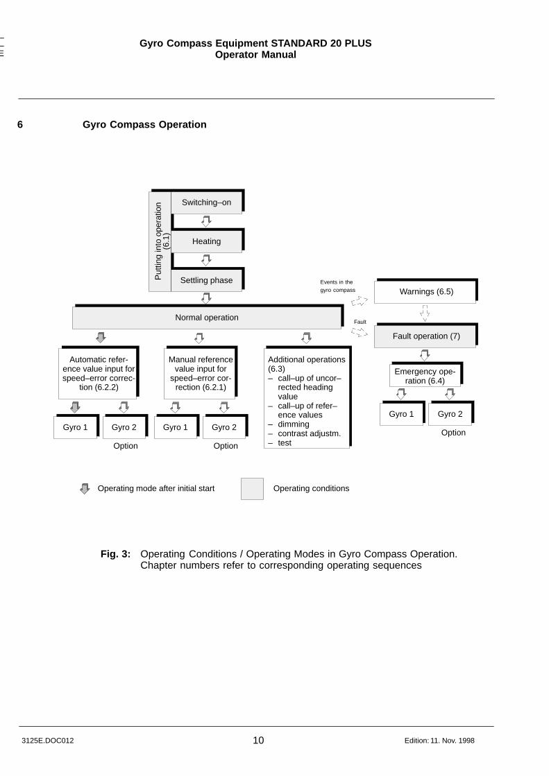
6 Gyro Compass Operation
Switching–on
Heating
Settling phasePut
ting
into
ope
ratio
n
Normal operation
Gyro 1 Gyro 2 Gyro 1 Gyro 2
Fault operation (7)
Emergency ope-ration (6.4)
Gyro 1 Gyro 2
Fig. 3: Operating Conditions / Operating Modes in Gyro Compass Operation.Chapter numbers refer to corresponding operating sequences
Operating mode after initial start
Option Option
Option
Warnings (6.5)
Operating conditions
(6.1
)
Automatic refer-ence value input forspeed–error correc-
tion (6.2.2)
Manual referencevalue input for
speed–error cor-rection (6.2.1)
Additional operations(6.3)– call–up of uncor–
rected heading value
– call–up of refer–ence values
– dimming– contrast adjustm.– test
Fault
Events in thegyro compass

Gyro Compass Equipment STANDARD 20 PLUSOperator Manual
GYROCOMPASSEQUIPMENT
Edition: 11. Nov. 1998 3125E.DOC01211
6.1 Putting into Operation
Indications Comments,Notes
� Switching–on the 24 V Navigation or Power Supply (refer to Section 4)
Single system Twin system
G1: Heating G1: HeatingG2: Heating
Gyro compass:
Gyro1
Gyro2
Gyro1
Gyro2
Adopted operation mode after switching–on:Gyro compass operation with automatic refer-ence value input for speed–error correction andselected gyro compass 1.
Gyro compass in the heating phase
Heating phase
Gyro com ass:
Repeater compass:
(yellow)
Display of temperature of supporting liquid in °C
� Checking the Reference Values for Latitude (Lat.)a) with Automatic Reference Value Input (Aut )
Lat.
Set
Aut Lat.:51 ° 12’use Set / Lat Set
Set
Check the correctness of the reference valuesat all costs, otherwise speed–error correctioncannot be guaranteed!(Refer also to 6.3.2)
1st line:– current reference value of the sensors
Confirm correct reference values with key Set;otherwise, switch–over to manual value input.(refer to 6.2.1)
Important Note:If the equipment is configured to the overriding navi-gation system (Sys ), then the automatic referencevalue input (Aut ) is usually without function. Whenthe Lat. key is pressed, in the display appears:
Aut Lat.:00 ° 00’Not connected

Gyro Compass Equipment STANDARD 20 PLUSOperator Manual
––E
Edition: 11. Nov. 19983125E.DOC012 12
Indications Comments,Notes
b) Option: Reference Value Input from the overriding Navigation System (Sys )
Lat.
Set
Sys Lat.:51 ° 12’use Set / Lat Set
Set
Check the correctness of the reference valuesat all costs, otherwise speed–error correctioncannot be guaranteed!(Refer also to 6.3.2)
1st line:– current reference value of the overriding
navigation system
Confirm correct reference values with key Set;otherwise, switch–over to manual value input.(refer to 6.2.1)
� Checking the Reference Values for Speed (Spd.)a) with Automatic Reference Value Input (Aut )
Speed
Set
Aut Spd:+0.8ktsuse Set / Spd
Set
Set
Check the correctness of the reference valuesat all costs, otherwise speed–error correctioncannot be guaranteed!(Refer also to 6.3.2)
1st line:– current reference value of the sensors
Confirm correct reference values with key Set;otherwise, switch–over to manual value input.(refer to 6.2.1)
Important Note:If the equipment is configured to the overriding navi-gation system (Sys ), then the automatic referencevalue input (Aut ) is usually without function. Whenthe Speed key is pressed, in the display appears:
Aut Spd:+00.0ktsNot connected

Gyro Compass Equipment STANDARD 20 PLUSOperator Manual
GYROCOMPASSEQUIPMENT
Edition: 11. Nov. 1998 3125E.DOC01213
Indications Comments,Notes
b) Option: Reference Value Input from the overriding Navigation System (Sys )
Speed
Set
Sys Spd:+0.8ktsuse Set / Spd Set
Set
Check the correctness of the reference valuesat all costs, otherwise speed–error correctioncannot be guaranteed!(Refer also to 6.3.2)
1st line:– current reference value of the overriding
navigation system
Confirm correct reference values with key Set;otherwise, switch–over to manual value input.(refer to 6.2.1)
� Automatical Display of the Heading Value
Single system Twin system
G1: 130.5 ° NSet G1: 130.5 ° NSetG2: Standby NSet
Gyro compass:
Repeater compass:
or:
G2: 130.7 ° NSetG1: Standby NSet
(yellow)
After reaching the lower operating temperatureof 45 °C, automatic display of the heading value
Heading value still imprecise and not usable!
Additional point signalizes:Settling procedure not yet completed

Gyro Compass Equipment STANDARD 20 PLUSOperator Manual
––E
Edition: 11. Nov. 19983125E.DOC012 14
Indications Comments,Notes
� Automatical Display of the Valid, Corrected Heading Value
Single system Twin system
G1: 131.8 G1: 131.8 °G2: Standby
Gyro compass:
Repeater compass:(green)
Gyro compass is ready for operation afterapprox. 3 hrs. settling timefrom now, display of valid, corrected headingvalue of gyro compass 1
Accuracy:After approx. 3 hrs.: better 2°After approx. 5 hrs.: better 0.1° x 1/cos latitude
Display of the uncorrected (!) heading on thegyro compass
Display of the corrected heading
6.1.1 Possibility of Calling up the Momentary Supporting Liquid Temperature
Indications Comments,Notes
or:
Gyro1
Gyro2
Single system Twin system
Temperat. 42.3 °C Temperat. 42.3 °CG2: Heating
Heating phase
Gyro compass:
Repeater compass:
(yellow)
or:
Temperat. 44.7 °CG1: Heating
Can be performed only in the time betweenswitching–on � and automatic heading indica-tion � (heating phase)
Display of the supporting liquid temperaturewhilst pressing the key
In case of a call for the compass that is not se-lected, this compass is simultaneously switchedover to.
With single systems, pressing the key Gyro 2has no effect
Display of the supporting liquid temperature in °C

Gyro Compass Equipment STANDARD 20 PLUSOperator Manual
GYROCOMPASSEQUIPMENT
Edition: 11. Nov. 1998 3125E.DOC01215
6.1.2 Possibility of Calling up the Previous Settling Time
Indications Comments,Notes
or:
Gyro1
Gyro2
Single system Twin system
Not Settled 1.4h Not Settled 1.4hG2: Standby NSet
or:
Not Settled 1.3hG1: Standby NSet
Can be performed only in the time between au-tomatic heading indication � and automaticindication of the valid, corrected heading value� (settling time)
Display of the previous settling time whilstpressing the key
In case of a call for the compass that is not se-lected, this compass is simultaneously switchedover to.
With single systems pressing the key Gyro 2has no effect
6.1.3 Possibility of Switching–over to Gyro Compass 2
Indications Comments,Notes
Gyro2
G2: 131.8 °G1: Standby
With single systems pressing the key Gyro 2has no effect

Gyro Compass Equipment STANDARD 20 PLUSOperator Manual
163125E.DOC012 Edition: 11. Nov. 1998
6.2 Operating Instructions with Normal Operation
6.2.1 Switching–over from Automatic to Manual Reference Value Input for the Speed–error Correction
For an optimal speed–error correction, the reference values mustcontinually be adapted to the current situation.If there are no compulsive reasons for a manual reference valueinput (e.g. breakdown in sensor/sensor not available), then auto-matic reference value input must always be selected.
Important Note:When switching–over from automatic to manual referencevalue input, a heading displacement may occur on the head-ing receivers connected. Therefore check, whether a new setheading must be entered to the autopilot (exception Autopi-lot Version NP 2000)!
6.2.1.1 Reference Value for Latitude (Lat.)
Indications Comments,Notes
� Calling up the Current Mode of Operation
Lat.
Aut Lat.:51 ° 12’use Set / Lat and:
Sys Lat.:51 ° 12’use Set / Lat
or optional:
Set
If the reference value is entered via the overriding navigation system (op–tionally configurable), in order to change to Man, the Lat. key must be pressed correspondingly often (see Section 3.1).
1st line:– Current reference value of the position re–
ceiver2nd line:– Request to switch–over to manual value
input (refer to � ) or to remain in the auto–matic value input(Set key)
� Switching–over the Operating Mode
Lat.Man Lat.:53 ° 28’
use ^ ∨ Set / Latand: Set
1st line:– Last manually input reference value2nd line:– Request to accept the displayed value
(refer to � ) or to accept a new value(refer to � and � )

GYROGyro Compass Equipment STANDARD 20 PLUSOperator Manual
COMPASSEQUIPMENT
17 3125E.DOC012Edition: 11. Nov. 1998
Indications Comments,Notes
� Changing values
or: Limit values ’Lat.’upper: 85° 00’lower: 00° 00’
Changing values (can be read–off at LCD dis-play):– stepwise by short actuation– continually by long actuationIf, after 7 s, these keys or the key Set are notactuated, then the yellow LED goes out and thesystem returns to its initial condition.Values outside of the limit values cannot be set.
� Accepting Values
SetG1: 153.7 ° Man
G1: 153.7 ° ManG2: Stdby(153.5 °)
or:
Single system
Twin system
Set
Accepting values and thereby switching–over tomanual reference value input for the speed–er-ror correction
Indication of the current, corrected headingvalue of the selected gyro compass.’Man’ signalizes selection of the manual refer-ence value input.
6.2.1.2 Reference Value for Speed (Spd.)
Indications Comments,Notes
� Calling up the Current Mode of Operation
SpeedAut Spd:+0.8ktsuse Set / Spd and:
Sys Spd:+0.8ktsuse Set / Spd
or optional:
Set
If the reference value is entered via the overriding navigation system (op–tionally configurable), in order to change to Man, the Speed key must be pressed correspondingly often (see Section 3.1).
1st line:– Current reference value of the log2nd line:– Request to switch–over to manual value
input (refer to � ) or to remain in the auto–matic value input(Set key)

Gyro Compass Equipment STANDARD 20 PLUSOperator Manual
183125E.DOC012 Edition: 11. Nov. 1998
Indications Comments,Notes
� Switching–over the Operating Mode
SpeedMan Spd:+0.9kts
use ^ ∨ Set / Spdand: Set
1st line:– Last manually inputted reference value2nd line:– Request to accept the displayed value
(refer to � ) or to accept a new value(refer to � and � )
� Changing values
or: Limit values ’Speed’upper: + 90.0 knlower: – 90.0 kn
Changing values (can be read–off at LCD dis-play):– stepwise by short actuation– continually by long actuationIf, after 7 s, these keys or the key Set are notactuated, then the yellow LED goes out and thesystem returns to its initial condition.Values outside of the limit values cannot be set.
� Accepting Values
SetG1: 153.7 ° Man
G1: 153.7 ° ManG2: Stdby(153.5 °)
or:
Single system
Twin system
Set
Accepting values and thereby switching–over tomanual reference value input for the speed–er-ror correction
Indication of the current, corrected headingvalue of the selected gyro compass.Man signalizes selection of the manual refer-ence value input.

GYROGyro Compass Equipment STANDARD 20 PLUSOperator Manual
COMPASSEQUIPMENT
19 3125E.DOC012Edition: 11. Nov. 1998
6.2.2 Switching–over from Manual to Automatic Reference Value Input for the Speed–
error Correction
For an optimal speed–error correction the reference values of the sensors mustbe correct.Before switching–over to automatic reference value input operating mode, thesensor values must therefore be checked.
Importatnt Note:If the equipment is configured to the overriding navigation system (Sys ), then theautomatic reference value input (Aut ) is usually without function. When the Lat.or Speed key is pressed, in the 2nd line of the display appears: Not connected
6.2.2.1 Reference Value for Latitude (Lat.)
Indications Comments,Notes
� Calling up the Operation Mode
Lat.Man Lat.:53 ° 28’
use ^ ∨ Set / Latand: Set
1st line:– Last manually inputted reference value
2nd line:– Request to switch over to automatic
value input (refer to � ) or to remain in manual value input(key Set)
� Switching–over the Operating Mode
Lat.Aut Lat.:51 ° 12’use Set / Lat
Aut Lat.:00 ° 00’Not connected
and:
and:
Set
Set
1st line:– Current reference value of the position re–
ceiver
2nd line:– Request to switch–over to automatic
value input (refer to � ) or to remain in manual value input(key Lat )
Position receiver not ready for operation– Switching–over not possible– Display of the last received reference value

Gyro Compass Equipment STANDARD 20 PLUSOperator Manual
203125E.DOC012 Edition: 11. Nov. 1998
Indications Comments,Notes
� Accepting the Operating Mode
Set
G1: 153.7 °
G1: 153.7 °G2: Stdby(153.5 °)
or:
Single system
Twin system
Set
Indication of the current, corrected headingvalue of the selected gyro compass
6.2.2.2 Reference Value for Speed (Spd.)
Indications Comments,Notes
� Calling up the Operation Mode
SpeedMan Spd:+0.9kts
use ^ ∨ Set / Spdand: Set
1st line:– Last manually inputted reference value
2nd line:– Request to switch over to automatic
value input (refer to � ) or to remain in manual value input(key Set)
� Switching–over the Operating Mode
SpeedAut Spd:+0.8ktsuse Set / Spd
Aut Spd:+00.0ktsNot connected
and:
and:
Set
Set
1st line:– Current reference value of the log
2nd line:– Request to switch–over to automatic
value input (refer to � ) or to remain in manual value input(key Speed )
Log not ready for operation– Switching–over not possible– Display of the last received reference value

GYROGyro Compass Equipment STANDARD 20 PLUSOperator Manual
COMPASSEQUIPMENT
21 3125E.DOC012Edition: 11. Nov. 1998
Indications Comments,Notes
� Accepting the Operating Mode
Set
G1: 153.7 °
G1: 153.7 °G2: Stdby(153.5 °)
or:
Single system
Twin system
Set
Indication of the current, corrected headingvalue of the selected gyro compass
Gyro Compass Equipment STANDARD 20 PLUSOperator Manual
223125E.DOC012 Edition: 11. Nov. 1998
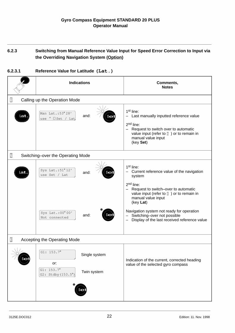
6.2.3 Switching from Manual Reference Value Input for Speed Error Correction to Input via
the Overriding Navigation System (Option )
6.2.3.1 Reference Value for Latitude (Lat.)
Indications Comments,Notes
� Calling up the Operation Mode
Lat.Man Lat.:53 ° 28’
use ^ ∨ Set / Latand: Set
1st line:– Last manually inputted reference value
2nd line:– Request to switch over to automatic
value input (refer to � ) or to remain in manual value input(key Set)
� Switching–over the Operating Mode
Lat.Sys Lat.:51 ° 12’use Set / Lat
Sys Lat.:00 ° 00’Not connected
and:
and:
Set
Set
1st line:– Current reference value of the navigation
system
2nd line:– Request to switch–over to automatic
value input (refer to � ) or to remain in manual value input(key Lat )
Navigation system not ready for operation– Switching–over not possible– Display of the last received reference value
� Accepting the Operating Mode
Set
G1: 153.7 °
G1: 153.7 °G2: Stdby(153.5 °)
or:
Single system
Twin system
Set
Indication of the current, corrected headingvalue of the selected gyro compass

GYROGyro Compass Equipment STANDARD 20 PLUSOperator Manual
COMPASSEQUIPMENT
23 3125E.DOC012Edition: 11. Nov. 1998
6.2.3.2 Reference Value for Speed (Spd.)
Indications Comments,Notes
� Calling up the Operation Mode
SpeedMan Spd:+0.9kts
use ^ ∨ Set / Spdand: Set
1st line:– Last manually inputted reference value
2nd line:– Request to switch over to automatic
value input (refer to � ) or to remain in manual value input(key Set)
� Switching–over the Operating Mode
SpeedSys Spd:+0.8ktsuse Set / Spd
Sys Spd:+00.0ktsNot connected
and:
and:
Set
Set
1st line:– Current reference value of the navigation
system
2nd line:– Request to switch–over to automatic
value input (refer to � ) or to remain in manual value input(key Speed )
Navigation system not ready for operation– Switching–over not possible– Display of the last received reference value
� Accepting the Operating Mode
Set
G1: 153.7 °
G1: 153.7 °G2: Stdby(153.5 °)
or:
Single system
Twin system
Set
Indication of the current, corrected headingvalue of the selected gyro compass

Gyro Compass Equipment STANDARD 20 PLUSOperator Manual
243125E.DOC012 Edition: 11. Nov. 1998
6.3 Additional Operations in Normal Mode
6.3.1 Calling up the Uncorrected Heading Value
Indications Comments,Notes
or:
Gyro1
Gyro2
G1: 153.7 ° uncor G1: 153.7 ° uncorG2: Stdby(153.5 °)
G2: 153.7 ° uncorG1: Stdby(153.5 °)
or:
Single system Twin system
Indication of the uncorrected heading valuewhilst key is being pressed
In case of a call for the compass that is not se-lected, this compass is simultaneously switchedover to.
6.3.2 Calling up the Current Reference Values (Lat. und Spd.)
Indications Comments,Notes
Lat.
Speed
Set
and:
and:
oder:
oder:
Aut Lat.:51 ° 12’use Set / Lat
Man Lat.:53 ° 28’
use ^ ∨ Set / Lat
Man Spd:+0.9kts
use ^ ∨ Set / Spd
oder optional:Sys Lat.:53 ° 28’
use ^ ∨ Set / Lat
Sys Spd:+0.9kts
use ^ ∨ Set / Spd
oder optional:
Aut Spd:+0.8ktsuse Set / Spd
Set
Set
Set
In manual value input operating mode for thespeed–error correction:– Last manually inputted reference value
In automatic value input operating mode for thespeed–error correction:– Current reference value of the sensors
In operating mode ’Input of reference value viathe navigation system’:– current reference value
Switching back to display of the heading value

GYROGyro Compass Equipment STANDARD 20 PLUSOperator Manual
COMPASSEQUIPMENT
25 3125E.DOC012Edition: 11. Nov. 1998
6.3.3 Dimming
Indications Comments,Notes
or:
Aut Lat.:51 ° 12’use Set / Lat
Aut Lat.:51 ° 12’use Set / Lat
or:
e.g.:⇒
⇒
Continuous brightness adjustment– of the key illumination– of the LEDs (apart from alarm LED)– of the background illumination of the
LCD display
6.3.4 Contrast Adjustment of the LCD Display
Indications Comments,Notes
Set
or:
XXX Contrast XXX
use ^ ∨
After approx. 2 s, automatic switching back toheading display, if no key is pressed
6.3.5 Test
Indications Comments,Notes
simultaneously
Begin of Test
Software Version130–602P01E00.01
End of Test
e. g.:
Automatic test run for approx. 5 s
Check of– the LCD segments– the acoustic signalling– the LEDs at max. brightness– the key illumination at max. brightness
After completion of test, automatic switch– backto heading display.

Gyro Compass Equipment STANDARD 20 PLUSOperator Manual
263125E.DOC012 Edition: 11. Nov. 1998
6.4 Emergency Operation
Change–over to emergency operation in case of failure of theelectronics for correction computation.Measure to be taken for certain system errors (see Section 7)
Caution!
No speed–error correction is carried out in emergency op-
eration!
Manual correction of the speed error see Description No. 110–800.DOC012 ’Gyro Compass STANDARD 20’, Section 4
Gyro 2
Gyro 1
LED(yellow)
Fig. 4: Position of Switches B14 and B15 in the Control Unit
Caution!Switches to be actu-ated by hand only!
Indications Comments,Notes
� Switching–over to Emergency Operation
LED(yellow)
Emergency operation (without speed–error cor-rection)Switching–over with Switch B15(refer to Fig. 4)

GYROGyro Compass Equipment STANDARD 20 PLUSOperator Manual
COMPASSEQUIPMENT
27 3125E.DOC012Edition: 11. Nov. 1998
Indications Comments,Notes
� Selection of the Gyro Compass
Gyro 2
Gyro 1
Selection of the gyro compass intended tomake available the heading signal by means ofswitch B14(refer to Fig. 4)
� After Switching–over to Emergency Operation
see �
Single system Twin system
G1: 153.7 ° uncor EG2: Standby E
G1: 153.7 ° uncor E
or:
G2: 153.7 ° uncor EG1: Standby E
– Gyro compass 1 selected
– Gyro compass 2 selected
� Calling up the Cause of Fault
or:
Gyro1
Gyro2
Gyro2
Single system Twin system
Emergency ModeG2: Standby E
or:
Emergency Mode
Emergency ModeG1: Standby E
G1: 153.7 ° uncor EEmergency Mode
– with gyro compass 1 selected
– with gyro compass 2 selected
– in case of a non–selected gyro compass (e.g. Gyro 2)
Switching–over to standby gyro compass isnot possible via the keys, but only viaswitch B 14.
� Switching–over to Normal Operation after Fault Correction
LED(yellow)
Normal operation (with speed–error correction)Switching–over with switch B15(see Fig. 4)

Gyro Compass Equipment STANDARD 20 PLUSOperator Manual
283125E.DOC012 Edition: 09. Sept. 1999
6.5 Warnings by Events at the Gyro Compass
The function of the gyro compass equipment is not restrictedwhen warnings occur! A possible breakdown can be avoided by correcting the faultin a timely manner.
Indications Comments,Notes
� Signalling
G1: 153.7 ° cG2: Stdby(153.5 °)
G1: 153.7 ° c
Single system Twin system
or:
G2: 153.7 ° cG1: Stdby(153.5 °)
c flashes
c flashes
Signalling (c = caution) only when gyro com-pass is selected
� Calling up the Cause of the Warning
or:
Gyro1
Gyro2
Single system Twin system
Warn: FanG2: Stdby(153.5 °)
or:Warn: FanG1: Stdby(153.5 °)
Warn: Fan
e. g.:
Indication of the cause of the warning whilstpressing the key.
If several warnings are waiting then these aredisplayed one after the other whilst the key ispressed.
� Corrective MeasuresRefer to Description No. 110–800.DOC012
Survey of possible warnings:
Display on Display on operator unit Descriptiongyro compass
c1 Warn: Fan Ventilator, function inhibitedc2 Warn: Heating Heating, function inhibitedc3 Warn: Temp > 65 °C Temperature of supporting liquid > 65 °Cc4 Warn: Temp Contr. Temperature regulator, function inhibitedc5 refer to 2.6.2.1 Interruption of supply voltage at a supporting
liquid temperature ≥ 45 °C (follow–up switched on)
c6 *) Warn: Height Height of gyrosphere outside of tolerance
After the cause of the warning has been corrected, the flashing c automatically goes out.
*) Valid from software version P02 E02.02

GYROGyro Compass Equipment STANDARD 20 PLUSOperator Manual
COMPASSEQUIPMENT
29 3125E.DOC012Edition: 11. Nov. 1998
7 Fault Operation
The equipment is operating faultily when it determines a fault via its permanent self test and
emits an alarm message.
7.1 Survey of Alarms on the Components of the Equipment
Operator Unit Gyro compass Repeater Compass
– Fault in gyro compass
Fault name flashes*)
and
E1 – E9
(red)
– System fault
Fault name flashes*)
and
current headingvalue
(red)
– Fault in repeater compass (refer to Description No. 133–555.DOC012, Section 6)
– –
(red)
or:
*) when gyro compass operation is not selected, only constant display Failure
Refer to the respective equipment manuals for the be-haviour of other system components when in fault opera-tion and the measures to be taken in these cases.

Gyro Compass Equipment STANDARD 20 PLUSOperator Manual
303125E.DOC012 Edition: 18. Mar. 1999
7.2 Procedure in Case an Alarm occurs
– Occurence of an alarm: and
– Acknowledge an alarm: (audible alarm ceases, LED shows continuous light)
– Call up fault name: Gyro1
Gyro2or or (whilst pressing the key)
– Immediately take the following measures
– switch–over to available redundant operating modes (manual reference value
input – if possible – , emergency operation) or to available standby gyro compass
– fault correction with means on–board ship (replacement parts), or
– contact Raytheon Marine Service.
To help you to react quickly in case of a fault, the following chapters are constructed as fol-
lows:
– Alarm survey 7.2.2 shows at a glance all possible alarm signallings and conditions
after acknowledgement
– Fault list 7.2.3 contains the fault names in alphabetical order

GYROGyro Compass Equipment STANDARD 20 PLUSOperator Manual
COMPASSEQUIPMENT
31 3125E.DOC012Edition: 18. Mar. 1999
7.2.1 Automatic Switch–over (with Twin Equipment only)
With appropriate configuration on the operator unit STANDARD 20: In case of failure of onegyro compass automatic change–over to the other gyro compass by the control unit.
Indications Comnments,Notes
� Failure of one Gyro Compass
Sensor failureswitched to G2
Sensor failureswitched to G1
or: and
G2: 187,8 °G1: 187,4 ° E
G1: 187,4 °G2: Failure
or: and
and
and
G2: 187,8 °G1: 187,4 ° E
G1: 187,4 °G2: Failure
or:
Indication of a sensor failure and change–over to the other gyro compassAlarm LED flashesAcoustic alarm sounds
After acknowledgement:Heading indication of the compass whichis ready for workLED offAcoustic alarm silent
Survey of Alarms see Section 7.2.2
� Failure in Attitude Reference System MINS
Sensor failureswitched to G1
and
G1: 187,8 °MI: 187,6 ° E
and
and
andG1: 187,8 °MI: Failure
or
Indication of a sensor failure and change–over to the gyro compass Alarm LED flashesAcoustic alarm sounds
After acknowledgement:Heading indication of the compassLED offAcoustic alarm silent
Survey of Alarms see Handbook MINS

Gyro Compass Equipment STANDARD 20 PLUSOperator Manual
323125E.DOC012 Edition: 18. Mar. 1999
7.2.2 Survey of Alarms
Alarm display Display afteracknowledgement
Call up fault name Comments
or:
and
Fault name flashes
Fault nameG2:Stdby(153.5 °)
flashes
or:
and
G1: 120.5 ° E
G1: 120.5 ° EG2: Stdby(153.5 °)
or:
Fault name
Fault nameG2: Stdby(153.5 °)
orGyro1
or:
and
Fault name flashes
flashesFault nameG2:Stdby(153.5 °)
or:
and
G1: not avail.E
G1: not avail.EG2: Stdby(153.5 °)
or:
Fault name
Fault nameG2: Stdby(153.5 °)
orGyro1 Refer to fault list
Section 7.2.3
Fault names are listedin alphabetical order
and
G1: 123.7 °G2: Failure
not applicable, asno alarm signalling
G1: 123.7 °Fault name
Gyro2
and
G1: 135.9 ° EDifference Alarm
E flashes
flashes
G1: 135.9 ° EG2: (138.3 °)
and
G1–G2:DifferenceG2: (138.3 °)
orGyro1

33 3125E.DOC012Edition: 1
Survey of Alarms (Cont.)
Display Display afterAcknowledgement
Signification Possible Cause Effect on Operation Measures
and
CheckValues
flashes
and
G1: 127.3 °G2: Stdby(153.5 °)
e. g.:
Display of current sys-tem condition
Request to check the– inputted values– configuration in the service
mode
Fault in data storage, systemexecutes initial start
Initial start results in:• all manually inputted
values are set to 0• operating mode ’gyro
compass operation with autom. reference value input’ is selected
• the configuration in theservice mode is set to default values
Select oper. mode suited to thesystem configuration and situa-tion and input new referencevalues, if necessary.(Refer to service manual ’Gyro Compass Equipment STANDARD 20 PLUS)
and
Check Values
flashes
and
Ext.Pos.Error
After further ac-knowledgement:
or
Ext.Spd.Error
G1:127.3 ° uncor E
GPS and/or Log faulty, causingfailure of the speed error correc-tion.
Request to check the configura-tion in the service mode
Gyro compass system executesinitial start; GPS or log failureshortly before the beginning of orduring the initial start, or whenGPS and log are not yet avail-able.
Initial start results in• all manually inputted values
are set to 0.• operating mode ’gyro
compass operation’ with automatic reference value input is selected
Now the uncorrected headingis transmitted to all connectedreceivers.
• the configuration in theservice mode is set to default values
• Make GPS or Log ready for operation
• Select oper. mode suited tothe system configuration andsituation and input new ref-erence values, if necessary.
(Refer to service manual ’Gyro Compass Equipment STANDARD 20 PLUS)
and
–––––––––––––––NO CONNECTION
and
–––––––––––––––NO CONNECTION
Data connection between controlunit and operator unit interrupted
• Cable connection, plug con–tacts
• Computer break down
Acc. to scope of fault• only operator unit display is
effected• automatic switch–over to
emergency operation (refer to 6.4)
Fault search, fault correction(refer to Service Manual3125E.DOC032)
and
–––––––––––––––NO TELEGRAMS
and
–––––––––––––––NO TELEGRAMS
Missing or faulty telegram fromcontrol unit to operator unit
Computer error Acc. to scope of fault• only operator unit display is
effected• all displays no longer follow
the heading change
• In total break down, select emergency operation (refer to 6.4)
• Fault search / correction (refer to Service Manual 3125E.DOC032)

34 3125E.DOC012Edition: 11. Nov. 1998
Display Display afterAcknowledgement
Signification Possible Cause Effect on Operation Measures
not accepted
After pressing the flashingkey Set:
Momentary, then back to in-itial setting
inapplicable, as noalarm signalling
Data not accepted Fault during data transmission New values not accepted Repeat procedure
and
G1: Volt.Interr. flashes
G1: Volt.Interr.G2: Stdby(153.5 °)
flashes
or:
and
G1: 127.3 ° NSet
or:
G1: 127.3 ° NSetG2: Stdby(153.5 °)
Gyro compass in settling phase(refer also to 6.1)
Warning c5:Interruption in supply voltage (refer also to 6.5)
Displayed heading value still imprecise and not usable
• Select standby compass(refer to 6.1.3)
or, during the settling phase• Read–off heading informa–
tion directly from magnetic compass
or:
G1: –––.– °
G1: –––.– °G2:Stdby(–––.– °)
inapplicable, as noalarm signalling
No valid heading telegram on thebus
Connection of operator unit tocontrol unit incorrect
Only operator unit display is affected
Correct the plug connection

35 3125E.DOC012Edition: 11. Nov. 1998
7.2.3 Fault List
No. Fault Name Signification Possible Cause Effect on Operation Measure
1 Configurat.ErrorSystem FaultFault in the configuration (onlypossible when PCB is changed)
False jumpering or position of DIPswitch on the STD 20 extension PCB
Displays no longer follow the headingchange
Configure new PCB correctly (refer to Service Manual 3125E.DOC032)
2 CU Ext.PCB Err.System FaultBreakdown of STD 20 extensionPCB
Extension PCB defective Displays no longer follow the headingchange
• Select emergency operation(refer to 6.4); system poss. switches automatically to emergency operation
• Fault search, fault correction(refer to Service Manual 3125E.DOC032)
3 G1–G2:DifferenceG2: (138.3 °)
Diff. of both corrected headingvalues > 3 °(preset limit value); during settlingphase for 3 hours no monitoring;then the compass is ready for op-eration, and for further 3 hours thelimit value is doubled to be 6°.
Note: In special cases, the limitvalue can be increased by theservice.
Fault in gyro compass (except E1 – E9)
Displayed heading values of both gyrocompasses could be wrong
• Compare both corrected gyro com–pass headings with the corrected magnetic compass heading (consider variation and deviation) Select the gyro compass whose heading value is nearest to the magnetic compass heading.Or:
• Select emergency operation (refer to 6.4)
• Fault search, fault correction(refer to Service Manual3125E.DOC032)
4 Distrbut.ErrorSystem FaultBreakdown in distribution
The distributor built into the con-trol unit indicates a breakdown onthe distribution PCB
Displays no longer follow the headingchange
• Read off heading value from magnetic compass
• Fault search, fault correction(refer to Service Manual3125E.DOC032)
5 EncoderGyro Compass Fault E3 Encoder faulty
Respective gyro compass supplies noheading values, displays no longer followthe heading change
• In single systems, try a restart by switching off/on, or:
• Select standby compass (refer to 6.1.3) or:
• Read–off heading information directly from the magnetic compass
• Fault search, fault correction(refer to Service Manual 110–800.DOC032)

36 3125E.DOC012Edition: 11. Nov. 1998
No. Fault Name Signification Possible Cause Effect on Operation Measure
6 Ext. Gyro SupplySystem FaultBreakdown in supply voltage forgyro 1 or gyro 2, resp.
According DC / DC converter incontrol unit is defective; wiringfault
Belonging gyro compass supplies noheading values
• Leave gyro compass 1 selected or:
• Switch over to the other gyro com–pass (refer to 6.1.3)
• Fault search, fault correction (refer to Service Manual110–800.DOC032)
7 Extern Pos ErrorSystem FaultBreakdown in position reference
Position receiver defective or notswitched on; wiring fault
Only operator unit indication is affected;the heading value indication for the repeater compasses remains valid! Speederror correction operates with the lastvalid value of the position receiver.
• Make position receiver ready for operation (refer to equipment manual ’Position Receiver’) or:
• Input current latitude values manually (refer to 6.2.1.1)
• Fault search, fault correction(refer to equipment man. ’Position Receiver’)
8 Extern Spd ErrorSystem FaultBreakdown in speed reference
Log defective or not switched on;wiring fault
Only operator unit indication is affected;the heading value indication for the repeater compasses remains valid! Speederror correction operates with the lastvalid value of the log.
• Make log ready for operation(refer to equipment manual ’Log’) or:
• Input current speed values manually (refer to 6.2.1.2)
• Fault search, fault correction(refer to equipment manual ’Log’)
9 Follow–upGyro Compass Fault E5 Follow–up faulty
Respective gyro compass supplies no
• In single systems, try a restart by switching off/on, or:
• Select standby compass (refer to 6.1.3) or:
10 Gyro currentGyro Compass Fault E4 Gyro current faulty
Respective gyro compass supplies noheading values, displays no longer followthe heading change
or:• Read–off heading information directly
from the magnetic compass• Fault search, fault correction
(refer to Service Manual 110–800.DOC032)

37 3125E.DOC012Edition: 11. Nov. 1998
Fault List (Cont.)
No. Fault Name Signification Possible Cause Effect on Operation Measure
11 Gyro ErrorSystem FaultBreakdown in data transfer fromgyro compass to control unit
Breakdown in gyro compass incable connection between com-pass and control unit or fault incontrol unit
Displays no longer follow the headingchange
• In single systems, try a restart by switching off/on, or:
• Select standby compass(refer to 6.1.3) or:
• Select emergency operationb (refer to 6.4)
• Fault search, fault correction (refer to Service Manual 3125E.DOC032 or Service Manual 110–800.DOC032)
12 Gyro SupplyGyro Compass Fault E2 Gyro supply faulty
13 HeatingGyro Compass Fault E8 Breakdown in heating • In single systems, try a restart by
switching off/on, or:
• Select standby compass
14 Height Gyrosph.Gyro Compass Fault E7 Height of the gyroshphere outside
of toleranceRespective gyro compass supplies noheading values, displays no longer followth h di h
Select standby com ass (refer to 6.1.3) or:
• Read–off heading information directly from the magnetic compassF lt h f lt ti
15 Operating Volt.Gyro Compass Fault E1 Operating voltage in compass is
faulty
g , y gthe heading change
g• Fault search, fault correction
(refer to Service Manual 110–800.DOC032)
16 Overtemp. >70 °CGyro Compass Fault E9 Overtemperature > 70 °C; all con-
nected heading displays nolonger follow the heading change
17 Temp. Sensor Gyro Compass Fault E6 Temperature sensor breakdown

Gyro Compass Equipment STANDARD 20 PLUSOperator Manual
––E
Edition: 18. Mar. 19993125E.DOC012 38

Gyro Compass Equipment STANDARD 20 PLUSOperator Manual
GYROCOMPASSEQUIPMENT
Annex 1 3125E.DOC012Edition: 11. Nov. 1998
2
• Selection of gyro compass 1 or 2corresponding LED lights up
• Call–up of status of selected gyrocompass in the heating and settlingphase
• Call–up of alarm cause after ac–knowledgement
• Call–up of uncorrected heading value of the selected gyro compass
• Call–up of the current latitude or speed values (reference values) andoperating mode
• Operating mode switch–over afterrenewed actuationTake–over by Set key
• Dimmer ,continuous change in brightness
• Value adjustment ,for speed and latitude in the respective op–erating mode Man (manual reference input)
• Testautomatic test run after simultaneous press–ing of the keys andCheck of– the LCD segments– the acoustic signal– the LEDs with the most brightness– the key illumination with the most bright–
nessDisplay of current software version
• Take–overLED flashes after pressing key Lat.or SpeedRequest for take–over after– reference value adjustment– operating mode switch over
• Call: contrast adjustment LCD–display(only possible when LED is notflashing)Contrast change with and
Alarm signalling and ac-knowledgement
LCD–Display• 1st line
– Status or heading value of theselected compass
– Current speed or latitudevalue (reference value)
– Alarms, warnings, operatingnotes
• 2nd line– Status of the second compass in
twin systems– Alarms, warnings, operating
notes
Fig. 1: Operating and Indicating Units
Gyro Compass Equipment STANDARD 20 PLUSOperator Manual
GYROCOMPASSEQUIPMENT
Annex 2 3125E.DOC012Edition: 11. Nov. 1998
Display of– the supporting liquid temperature during
the heating phase– the (still) imprecise heading value duringthe settling phase
(flashing point)– the exact heading value after the settling
phase – of alarms (E1 to E9) and warnings
(c1 to c5)
Fig. 2: Digital Display on Gyro Compass STANDARD 20
Fig. 3: Operating and Indicating Units on Front Panel of the Repeater CompassType 133 – 555
Three–coloured LED(yellow, green, red)
Digital display (in connection withthree coloured LED)Display – of the heating phase and the settling
phase of the gyro compass– of the heading value of the gyrocom–
pass or magnetic compass– of faults in the repeater compass– of missing or faulty heading values
• Dimmer , orcontinuous brightness adjustment
• Select operating mode ’Correction’(both keys pressed for 10 s)single–key correction
• Select operating mode ’Test’(both keys pressed for 5 s)automatic lamp test
• Acknowledgement (Reset)of a waiting alarm
Illuminated panelOperating mode ’Correc-tion’ is selected
Illuminated panelOperating mode’Test’ is selected
Fig. 4: Operating and Indicating Units on Front Panel of the Repeater CompassType 133 – 556
Three–coloured LED(yellow, green, red)
Digital display (in connection withthree coloured LED)Display – of the heating phase and the settling
phase of the gyro compass– of the heading value of the gyro
compass or magnetic compass– of faults in the repeater compass– of missing or faulty heading values
• Dimmer , orcontinuous brightness adjustment
• Select operating mode ’Correction’(both keys pressed for 10 s)single–key correction
• Select operating mode ’Test’(both keys pressed for 5 s)automatic lamp test
• Acknowledgement (Reset)of a waiting alarm