Another Quality Product by Quanser Consultingse463/ResearchProject/Quanser/MultiQ-PCI...
60
Version 1.0 Another Quality Product by Quanser Consulting
Transcript of Another Quality Product by Quanser Consultingse463/ResearchProject/Quanser/MultiQ-PCI...
Version 1.0
Another Quality Product by Quanser Consulting

How to contact Quanser Consulting:
(905) 940-3575 Telephone
(905) 940-3576 Facsimile
80 Esna Park DriveMarkham, ONCanada L3R 2K8
http://www.quanser.com Web
mailto://[email protected] General information
MultiQ-PCI Data Acquisition System Reference Manual
MultiQ-PCI is a trademark of Quanser Consulting,Inc.Other brands and their products are trademarks or registered trademarks of their respective holders and shouldbe noted as such.
© 2000 Quanser Consulting Inc.All rights reserved. This work may not be translated or copied in whole or in part without the writtenpermission of the copyright holder, except under the terms of the associated software license agreement. Nopart of this manual may be photocopied or reproduced in any form.The use of general descriptive names, trade names, trademarks, etc. in this publication, even if the former arenot especially identified, is not to be taken as a sign that such names as understood by the Trade Marks andMerchandise Marks Act, may accordingly be used freely by anyone.
Printed in Canada.

Table of Contents
Table of Contents
1. Introduction............................................................................................11.1 Card Identification.............................................................................11.2 Installation...........................................................................................2
2. Board Overview......................................................................................32.1 Layout..................................................................................................32.2 Block Diagram.....................................................................................3
3. Initial States After Reset........................................................................53.1 Miscellaneous Registers......................................................................53.2 Digital I/O............................................................................................53.3 Counters...............................................................................................5
4. Digital I/O................................................................................................74.1 Overview..............................................................................................74.2 Writing to the Digital Outputs...........................................................8
4.2.1 Using Digital Outputs 0-5 as Counter Overflows.............94.3 Read the Digital Inputs.......................................................................94.4 Capturing Digital Input Edges..........................................................9
4.4.1 Selecting Positive or Negative Edge Capture..................104.4.2 Interrupting on Edge Capture..........................................104.4.3 Enabling and Disabling Edge Capture............................10
4.5 Reading Edge Capture Status Registers.........................................124.5.1 Reading which Channels have Captured Edges.............124.5.2 Reading the Status of the Interrupt Enable Registers. . .124.5.3 Reading the Status of the Edge Selection Register.........124.5.4 Reading the Status of the Capture Enable Register.......134.5.5 Clearing a Captured Edge................................................13
4.6 Digital Input Interrupts....................................................................134.6.1 Enabling Interrupt on Edge Capture..............................134.6.2 Digital Interrupt Handling................................................13
5. Counters...............................................................................................155.1 Overview............................................................................................15
5.1.1 Latches................................................................................155.1.2 Clear/Pre-load....................................................................165.1.3 Interrupts............................................................................165.1.4 Overflow Outputs..............................................................165.1.5 Index Inputs.......................................................................165.1.6 Counter Inputs...................................................................165.1.7 Power Failure.....................................................................175.1.8 Counter Registers..............................................................18
5.2 Encoder Connections........................................................................18
i
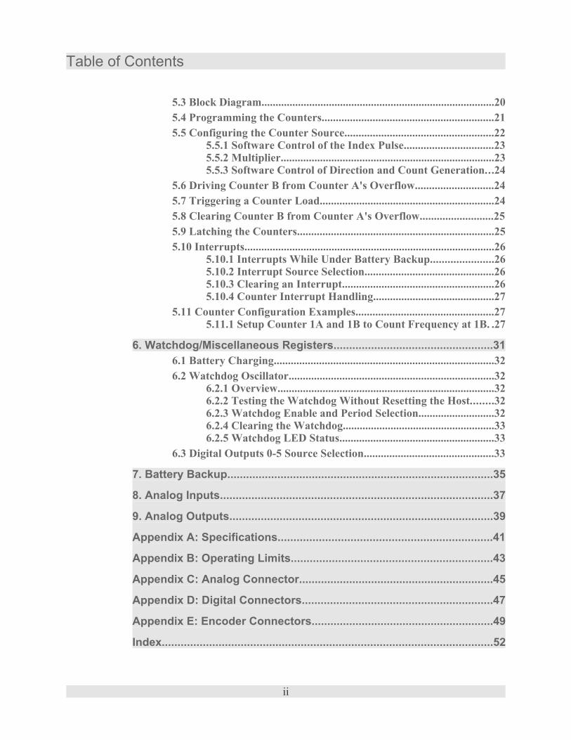
Table of Contents
5.3 Block Diagram...................................................................................205.4 Programming the Counters.............................................................215.5 Configuring the Counter Source.....................................................22
5.5.1 Software Control of the Index Pulse................................235.5.2 Multiplier............................................................................235.5.3 Software Control of Direction and Count Generation...24
5.6 Driving Counter B from Counter A's Overflow............................245.7 Triggering a Counter Load..............................................................245.8 Clearing Counter B from Counter A's Overflow..........................255.9 Latching the Counters......................................................................255.10 Interrupts.........................................................................................26
5.10.1 Interrupts While Under Battery Backup......................265.10.2 Interrupt Source Selection..............................................265.10.3 Clearing an Interrupt......................................................265.10.4 Counter Interrupt Handling...........................................27
5.11 Counter Configuration Examples.................................................275.11.1 Setup Counter 1A and 1B to Count Frequency at 1B. .27
6. Watchdog/Miscellaneous Registers...................................................316.1 Battery Charging..............................................................................326.2 Watchdog Oscillator.........................................................................32
6.2.1 Overview.............................................................................326.2.2 Testing the Watchdog Without Resetting the Host........326.2.3 Watchdog Enable and Period Selection...........................326.2.4 Clearing the Watchdog......................................................336.2.5 Watchdog LED Status.......................................................33
6.3 Digital Outputs 0-5 Source Selection..............................................33
7. Battery Backup.....................................................................................35
8. Analog Inputs.......................................................................................37
9. Analog Outputs....................................................................................39
Appendix A: Specifications....................................................................41
Appendix B: Operating Limits................................................................43
Appendix C: Analog Connector..............................................................45
Appendix D: Digital Connectors.............................................................47
Appendix E: Encoder Connectors..........................................................49
Index.........................................................................................................52
ii

List of Figures
List of Figures
Figure 1: MultiQ-PCI Data Acquisition Card..................................................................................2Figure 2: System Block Diagram.....................................................................................................4Figure 3: Digital I/O Channels.........................................................................................................7Figure 4: Differential pair encoder.................................................................................................18Figure 5: Single-ended encoder......................................................................................................18Figure 6: Single-ended event counter with external count direction and index control.................18Figure 7: Block diagram of a counter pair......................................................................................20Figure 8: Frequency counter block diagram and timing.................................................................28
iii

List of Tables
List of Tables
Table 1: Jumpers...............................................................................................................................3Table 2: MISC1 & MISC2 Registers Initial States..........................................................................5Table 3: Digital I/O Initial States......................................................................................................5Table 4: Counter Initial States..........................................................................................................5Table 5: Digital I/O Register Offsets................................................................................................8Table 6: Writing to Digital Outputs..................................................................................................8Table 7: Reading Digital Inputs........................................................................................................9Table 8: Selecting Positive or Negative Edge Capture...................................................................10Table 9: Enabling & Disabling Edge Capture................................................................................10Table 10: Reading Captured Edges................................................................................................12Table 11: Reading the Status of the Interrupt Enable Registers.....................................................12Table 12: Reading the Status of the Edge Selection Registers.......................................................12Table 13: Reading the Status of the Capture Enable Registers......................................................13Table 14: Enabling Interrupt on Edge Capture...............................................................................13Table 15: Counter Registers...........................................................................................................18Table 16: Encoder Channels...........................................................................................................19Table 17: CR1A 00 (hex) Read/Write............................................................................................21Table 18: CR1B 02 (hex) Read/Write............................................................................................21Table 19: CR1B 02 (hex) Read......................................................................................................21Table 20: Digital inputs as Counter input controls.........................................................................22Table 21: Write to MISC1 88 (hex)................................................................................................31Table 22: Read from MISC1 88 (hex)............................................................................................31Table 23: Write to MISC2 90 (hex)................................................................................................31Table 24: Read from MISC2 92 (hex)............................................................................................31Table 25: Reading back Digital Outputs 0-5 Source Selection......................................................33Table 26: General Specifications....................................................................................................41Table 27: Operating Limits.............................................................................................................43Table 28: J1 (50-pin IDC Ribbon Connector)...............................................................................45Table 29: J2 (50-pin IDC Ribbon Connector)...............................................................................47Table 30: J3 (50-pin IDC Ribbon Connector)...............................................................................47Table 31: J4 (26-pin IDC Ribbon Connector)...............................................................................49Table 32: J5 (26-pin IDC Ribbon Connector)...............................................................................49
iv

List of Examples
List of Examples
Example 1: Capturing Positive Edges on Channels 2, 9 and 14, Interrupting on 2 and 9..............11Example 2: Clearing an interrupt on Counter 2A...........................................................................26Example 3: Clearing an interrupt on Counter 2B...........................................................................27Example 4: Clearing an interrupt on Counter 3A and 3B..............................................................27Example 5: Frequency counter.......................................................................................................29
v
Introduction
1. IntroductionThe MultiQ-PCI card is a plug-and-play, multi-function I/O card. Some of its features in-clude:� 48 digital I/O channels.
� 20 of the digital I/O channels have edge detection and interrupt capability.� 7 of the digital outputs may be used as counter overflow outputs.
� Watchdog timer with several selectable reset periods that can reset the PCI bus.� Six 24 bit up/down counters arranged in 3 pairs with:
� inputs that can be driven in various modes (1x, 2x, 4x) from incremental encodersinputs, digital inputs, the paired counter’s overflow, the system clock or driven bysoftware.
� the ability to generate an interrupt on counter overflow or from encoder/digital inputindex pulse.
� the ability to be pre-loaded/cleared on a counter overflow.� the ability for the output of the second counter to be captured on the overflow of the
first.� the ability to be programmed as a periodic interrupt generator.� battery backup of the counter circuitry to prevent count loss during a power failure.
� Charge control of the backup Ni-Cad battery.� 16 differential analog inputs with 14 bit resolution.� 4 analog outputs with 13 bit resolution and remote sense inputs to compensate for any
external output resistance.
1.1 Card IdentificationThe MultiQ-PCI card may be identified in the PCI system using the following identifiers:
Vendor ID: 0x1131Device ID: 0x7146
MultiQ-PCI Reference Manual � 1

Installation
1.2 InstallationRefer to the MultiQ-PCI User's Guide for installation instructions, as well as detailed infor-mation about the MultiQ-PCI terminal board. Be sure to handle the card with caution. Thecard is shown in Figure 1 below.
The MultiQ-PCI data acquisition card is susceptible to damage from staticelectricity. Always ground yourself when installing the MultiQ-PCI card inyour computer!
To prevent ESD damage to the card:
• Do not remove the circuit board from its protective anti-static bag until you are ready toconfigure the board for installation.
• Handle the circuit board only at grounded, ESD protected stations.
• Remove power from the PCI system before installing or removing the circuit board.
2 � MultiQ-PCI Reference Manual
Figure 1: MultiQ-PCI Data Acquisition Card
J2 (Digital 0-23)J3 (Digital 24-47)
J1 (A/D and D/A)
J4 (Encoder 3-5)
J5 (Encoder 0-2)

Board Overview
2. Board Overview
2.1 LayoutThe layout of the MultiQ-PCI card is depicted in Figure 1. The connectors are labeled to fa-cilitate connection to the MultiQ-PCI terminal board. Detailed pin-outs for the connectorsmay be found in the appendices.Although most of the functionality of the board is software-programmable, some featurescan be enabled or disabled using jumpers on the board. Table 1 describes the jumpers onthe card.
Table 1: JumpersJumper Description
JP1 Watchdog timer PCI resetJP2 Battery connection for battery backup
JP3-JP6 D/A sense loopback
2.2 Block DiagramA schematic of the board is illustrated in Figure 2 on page 4. The schematic shows thefunctional components of the board. The board is functionally divided into five compo-nents:
� Counters.� Digital I/O� A/D Conversion� D/A Conversion� Watchdog Timer
The counters handle a broad variety of functionality, including edge capture, periodic inter-rupt generation, encoder inputs and more.The different components are described in detail in the proceeding chapters.
MultiQ-PCI Reference Manual � 3

Block Diagram
4 � MultiQ-PCI Reference Manual
Figure 2: System Block Diagram
ABIndex
EdgeCapture
&I/O Register
PCI Bus Inte
& Control lo
Interru
Watchdo10 Secon1 Second½ Second1/8 Second
D/A
1
4
Output
Output
Sense
Sense
A/D
1
16
+-
+-
PCI Bu
1
48
InOut
InOut
Digital I/O
Control registers
OverfloCountDirectio
Input Selecto
Pre-load / Clear
Output Latch
Counter(24 bit)
OverfloCountDirectio
Internal Cl
Software
ABIndex
Software
Overflo
Counter
Counter
Counters (1, 2, 3)
Input Selecto
Pre-load
Output Latch
Counter(24 bit)
Internal Clock
PCI Reset enablejumper
WatchdogTimeout
Interru
Index
Index

Initial States After Reset
3. Initial States After ResetThis section describes the state of the MultiQ-PCI registers on a hardware reset. The samestates result when the watchdog timer expires and the watchdog timer is enabled.
3.1 Miscellaneous RegistersTable 2: MISC1 & MISC2 Registers Initial States
Register or I/O State See PageWatchdog oscillator Oscillator 1 is selected.Watchdog DisabledMISC1 Write Enable Disabled.Watchdog period 1/
8th second
EDCAP 0
Watchdog/Miscellaneous Registers 31
3.2 Digital I/OTable 3: Digital I/O Initial States
Register or I/O State See PageDigital I/O 0-7 All inputs. (pull up resistors enabled)Digital I/O 8-47 Indeterminate (will depend on the inputs during reset)Digital I/O 0-5 Will work as digital inputs not counter overflows
Digital I/O 7
EDGSELINTSELCAPSEL
Cleared
3.3 CountersIf there is a charged external battery connected to the system then most of the functionalityof the counters is held through a reset/power failure. The interrupts are disabled to allowthe system time to get back up and running.
Table 4: Counter Initial StatesRegister or I/O State See PageCounter inputselectionEdge detectionMultiplierClear Counter BPre-load triggerPre-load registers
Unchanged Counters 15
MultiQ-PCI Reference Manual � 5


Digital I/O
4. Digital I/O
4.1 OverviewThe MultiQ-PCI board provides 48 digital I/O channels. 40 of these channels (channels 0-39) offer edge detection and interrupt on edge detection. Either a positive or negative edgecan be detected. The other 8 channels (40-47) have simple input/output functionality only.Each channel can function as an input or an output.
Any channel that is to be used as an input must have a ‘0’ written to its out-put control register. This ensures that the output transistor is turned off, al-lowing the pull-up resistor to pull the channel high. If a '0' is not writtenthen the transistor will have to sink high currents if the input is drivenhigh externally. (See Figure 3 “Digital I/O Channels” above.)
MultiQ-PCI Reference Manual � 7
Figure 3: Digital I/O Channels
EdgeCapture
&I/O Register
Interru
1
48
InOut
InOut
Digital I/O
PCI Bus Interfac
Control Logic

Overview
Table 5: Digital I/O Register OffsetsWrite
Offset(Hex)
Register Description
40 Not used42 WRINTSELA Interrupt Enable (0-15)44 WREDGSELA Edge Selection (0-15)46 WRCAPSELA Capture Enable (0-15)48 DOUTA Write to Digital Output (0-15)4A4C4E50
Not used
52 WRINTSELB Interrupt Enable (16-31)54 WREDGSELB Edge Selection (16-31)56 WRCAPSELB Capture Enable (16-31)58 DOUTB Write to Digital Output (16-31)5A5C5E60
Not used
62 WRINTSELC Interrupt Enable (32-47)64 WREDGSELC Edge Selection (32-47)66 WRCAPSELC Capture Enable (32-47)68 DOUTC Write to Digital Output (32-47)6A6C6E
Not used
ReadOffset(Hex)
Register Description
40424446
DINA Status of digital inputs (0-15)
48 RDCAPFLGA Edges captured so far (0-15)4A RDINTSELA Status of interrupt enable register A4C RDEDGSELA Status of edge selection register A4E RDCAPSELA Status of capture enable register A50525456
DINB Status of digital inputs (16-31)
58 RDCAPFLGB Edges captured so far (16-31)5A RDINTSELB Status of interrupt enable register B5C RDEDGSELB Status of edge selection register B5E RDCAPSELB Status of capture enable register B60626466
DINC Status of digital inputs (32-47)
68 RDCAPFLGC Edges captured so far (32-47)6A RDINTSELC Status of interrupt enable register C6C RDEDGSELC Status of edge selection register C6E RDCAPSELC Status of capture enable register C
4.2 Writing to the Digital OutputsThere are 3 digital output registers used to write to the outputs. The format of the data to bewritten to each register is shown below.
Table 6: Writing to Digital OutputsOffset(Hex)
RegisterName
Output Channel NumberBit 15 Bit 14 Bit 13 Bit 12 Bit 11 Bit 10 Bit 9 Bit 8 Bit 7 Bit 6 Bit 5 Bit 4 Bit 3 Bit 2 Bit 1 Bit 0
48 DOUTA 15 14 13 12 11 10 9 8 7 6 5 4 3 2 1 058 DOUTB 31 30 29 28 27 26 25 24 23 22 21 20 19 18 17 1668 DOUTC 47 46 45 44 43 42 41 40 39 38 37 36 35 34 33 32
8 � MultiQ-PCI Reference Manual

Writing to the Digital Outputs
Writing a “0” to a bit in the output register will cause the corresponding output to turn offand thus give an output of 5V. When a ‘1’ is written then the output transistor is turned oncausing the output channel to give an output of 0V.When an I/O channel is to be used as an input then a ‘0’ must be written to the correspond-ing bit of that channels output register. This is to prevent high currents caused if the outputtransistor is turned on while a 5V input signal is being applied to the input (see Figure 3 onpage 7).
4.2.1 Using Digital Outputs 0-5 as Counter OverflowsDigital outputs 0-5 can be setup to pull the corresponding output load low for a short pulse(500 nsecs) when the counters overflow. (See Table 23 "Write to MISC2 90 (hex)" on page31)
4.3 Read the Digital InputsThere are three digital input registers used to read the inputs. The format of the data re-turned by each register is shown in the table below.
Table 7: Reading Digital InputsOffset
(Hex)Register
NameInput Channel Number
Bit 15 Bit 14 Bit 13 Bit 12 Bit 11 Bit 10 Bit 9 Bit 8 Bit 7 Bit 6 Bit 5 Bit 4 Bit 3 Bit 2 Bit 1 Bit 0
40 DINA 15 14 13 12 11 10 9 8 7 6 5 4 3 2 1 050 DINB 31 30 29 28 27 26 25 24 23 22 21 20 19 18 17 1660 DINC 47 46 45 44 43 42 41 40 39 38 37 36 35 34 33 32
Each digital input has a 10K Ohm pull-up resistor to +5V. With a 5V input or no input con-nected a ‘0’ will be read from the digital input register. Pulling the input to ground willcause a ‘1’ to be read from the digital input register. The corresponding output registermust have “0” written to it before it can be used as an input.
4.4 Capturing Digital Input EdgesThis feature is not available on inputs 20-23 and 44-47 (the grayed out areas of the tables).Reading any edge capture data or interrupt data from these inputs will always return 0.Writing to any of edge capture or interrupt register for these inputs will have no effect.
MultiQ-PCI Reference Manual � 9

Capturing Digital Input Edges
4.4.1 Selecting Positive or Negative Edge CaptureTable 8: Selecting Positive or Negative Edge Capture
Offset(Hex)
RegisterName
Input Channel NumberBit 15 Bit 14 Bit 13 Bit 12 Bit 11 Bit 10 Bit 9 Bit 8 Bit 7 Bit 6 Bit 5 Bit 4 Bit 3 Bit 2 Bit 1 Bit 0
44 WREDSELA 15 14 13 12 11 10 9 8 7 6 5 4 3 2 1 054 WREDSELB 31 30 29 28 27 26 25 24 23 22 21 20 19 18 17 1664 WREDSELC 47 46 45 44 43 42 41 40 39 38 37 36 35 34 33 32
Write to the WREDSEL register with a ‘0’ to select negative edges (transition from 1 to 0)or a ‘1’ to select positive edges (transition from 0 to 1). Note that these will take effect onceedge capturing for a particular channel has been enabled.
4.4.2 Interrupting on Edge CaptureA captured edge is usually set up to be accompanied by an interrupt. (See “Enabling Inter-rupt on Edge Capture” on page 13). If this is not done then the RDCAPFLG will need to bepolled to see if an edge has occurred.
4.4.3 Enabling and Disabling Edge CaptureTable 9: Enabling & Disabling Edge Capture
Offset(Hex)
RegisterName
Input Channel NumberBit 15 Bit 14 Bit 13 Bit 12 Bit 11 Bit 10 Bit 9 Bit 8 Bit 7 Bit 6 Bit 5 Bit 4 Bit 3 Bit 2 Bit 1 Bit 0
42 WRCAPSELA 16 15 14 13 12 11 10 9 8 7 6 5 4 3 2 152 WRCAPSELB 32 31 30 29 28 27 26 25 24 23 22 21 20 19 18 1762 WRCAPSELC 48 47 46 45 44 43 42 41 40 39 38 37 36 35 34 33
Before any edges may be captured, the desired channel(s) must have edge-capturing en-abled. Enabling or disabling edge capture is done using the EDCAP bit of MISC1 in con-junction with the WRCAPSEL registers. When the EDCAP bit is set to '1', writing to aWRCAPSEL register will enable those channels with the corresponding bit set to 1. Whenthe EDCAP bit is set to '0', writing to a WRCAPSEL register will disable those channelswith the corresponding bit set to 1. Thus, to enable edge capture for a set of digital input channels:1. Write to the EDCAP bit of the MISC1 register.
‘1’ is used to enable one or more channels.‘0’ is used to disable one or more channels.
2. Write to the WRCAPSELA, WRCAPSELB or WRCAPSELC register to apply theabove command to those channels with their corresponding bits set to ‘1’ inWRCAPSELA, WRCAPSELB or WRCAPSELC.
10 � MultiQ-PCI Reference Manual
Capturing Digital Input Edges
MultiQ-PCI Reference Manual � 11
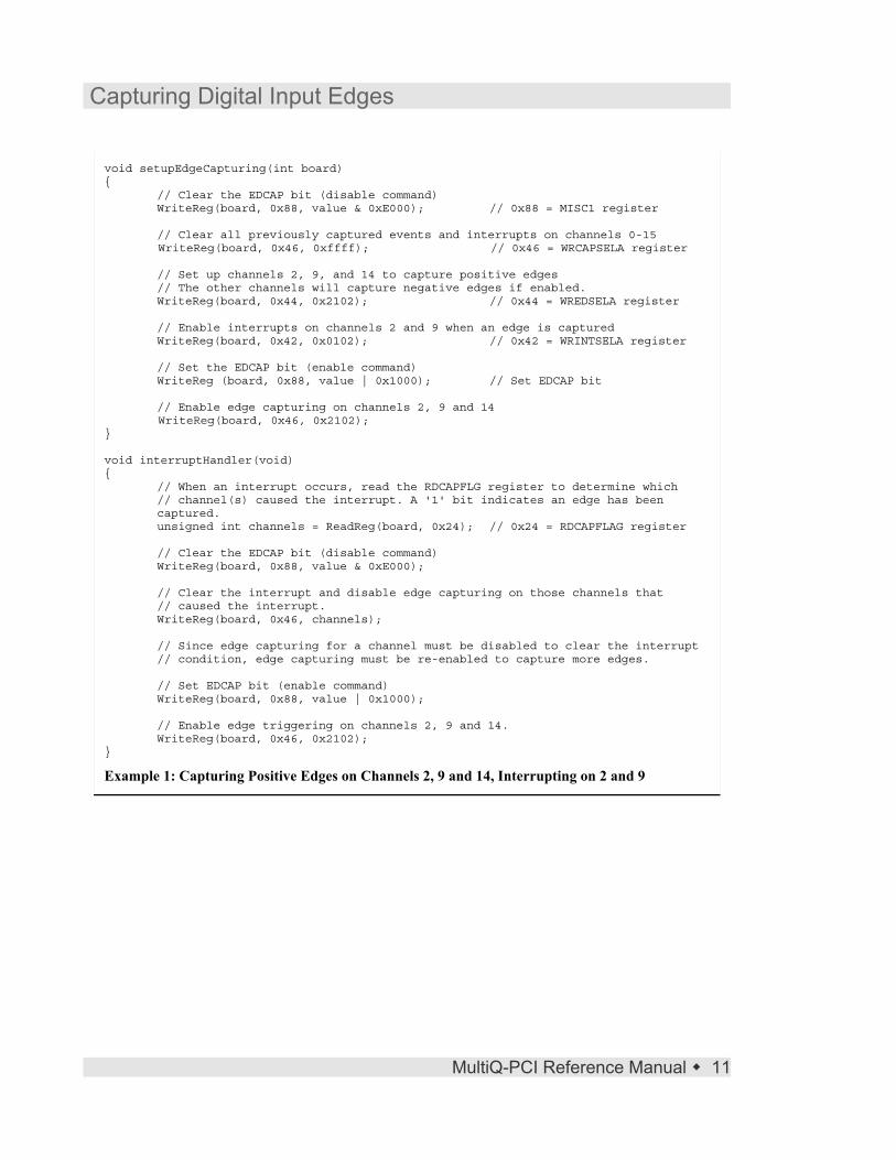
void setupEdgeCapturing(int board){
// Clear the EDCAP bit (disable command)WriteReg(board, 0x88, value & 0xE000); // 0x88 = MISC1 register
// Clear all previously captured events and interrupts on channels 0-15WriteReg(board, 0x46, 0xffff); // 0x46 = WRCAPSELA register
// Set up channels 2, 9, and 14 to capture positive edges// The other channels will capture negative edges if enabled.WriteReg(board, 0x44, 0x2102); // 0x44 = WREDSELA register
// Enable interrupts on channels 2 and 9 when an edge is capturedWriteReg(board, 0x42, 0x0102); // 0x42 = WRINTSELA register
// Set the EDCAP bit (enable command)WriteReg (board, 0x88, value | 0x1000); // Set EDCAP bit
// Enable edge capturing on channels 2, 9 and 14WriteReg(board, 0x46, 0x2102);
}
void interruptHandler(void){
// When an interrupt occurs, read the RDCAPFLG register to determine which// channel(s) caused the interrupt. A '1' bit indicates an edge has beencaptured.unsigned int channels = ReadReg(board, 0x24); // 0x24 = RDCAPFLAG register
// Clear the EDCAP bit (disable command)WriteReg(board, 0x88, value & 0xE000);
// Clear the interrupt and disable edge capturing on those channels that// caused the interrupt.WriteReg(board, 0x46, channels);
// Since edge capturing for a channel must be disabled to clear the interrupt// condition, edge capturing must be re-enabled to capture more edges.
// Set EDCAP bit (enable command)WriteReg(board, 0x88, value | 0x1000);
// Enable edge triggering on channels 2, 9 and 14.WriteReg(board, 0x46, 0x2102);
}
Example 1: Capturing Positive Edges on Channels 2, 9 and 14, Interrupting on 2 and 9

Reading Edge Capture Status Registers
4.5 Reading Edge Capture Status Registers
4.5.1 Reading which Channels have Captured EdgesTable 10: Reading Captured Edges
Offset(Hex)
RegisterName
Input Channel NumberBit 15 Bit 14 Bit 13 Bit 12 Bit 11 Bit 10 Bit 9 Bit 8 Bit 7 Bit 6 Bit 5 Bit 4 Bit 3 Bit 2 Bit 1 Bit 0
48 RDCAPFLGA 15 14 13 12 11 10 9 8 7 6 5 4 3 2 1 058 RDCAPFLGB 31 30 29 28 27 26 25 24 23 22 21 20 19 18 17 1668 RDCAPFLGC 47 46 45 44 43 42 41 40 39 38 37 36 35 34 33 32
RDCAPFLGA, RDCAPFLGB and RDCAPFLGC are used to determine which, if any,channels have captured edges. A ‘1’ shows an edge has been captured for the correspond-ing channel.
4.5.2 Reading the Status of the Interrupt Enable RegistersTable 11: Reading the Status of the Interrupt Enable Registers
Offset(Hex)
RegisterName
Input Channel NumberBit 15 Bit 14 Bit 13 Bit 12 Bit 11 Bit 10 Bit 9 Bit 8 Bit 7 Bit 6 Bit 5 Bit 4 Bit 3 Bit 2 Bit 1 Bit 0
4A RDINTREGA 15 14 13 12 11 10 9 8 7 6 5 4 3 2 1 05A RDINTREGB 31 30 29 28 27 26 25 24 23 22 21 20 19 18 17 166A RDINTREGC 47 46 45 44 43 42 41 40 39 38 37 36 35 34 33 32
RDINTREGA, RDCAPFLGB and RDCAPFLGC are used to determine which, if any,channels will generate an interrupt on an edge capture. A ‘1’ shows that the correspondingchannel will generate an interrupt on edge capture (if the channel is enabled).
4.5.3 Reading the Status of the Edge Selection RegisterTable 12: Reading the Status of the Edge Selection Registers
Offset(Hex)
RegisterName
Input Channel NumberBit 15 Bit 14 Bit 13 Bit 12 Bit 11 Bit 10 Bit 9 Bit 8 Bit 7 Bit 6 Bit 5 Bit 4 Bit 3 Bit 2 Bit 1 Bit 0
4C RDEDGREGA 15 14 13 12 11 10 9 8 7 6 5 4 3 2 1 05C RDEDGREGB 31 30 29 28 27 26 25 24 23 22 21 20 19 18 17 166C RDEDGREGC 47 46 45 44 43 42 41 40 39 38 37 36 35 34 33 32
RDEDGREGA, RDCAPFLGB and RDCAPFLGC are used to determine which channelswill capture positive edges and which will capture negative edges(when they are enabled).A transition from 0 to 1 is considered a positive edge.
12 � MultiQ-PCI Reference Manual
Reading Edge Capture Status Registers
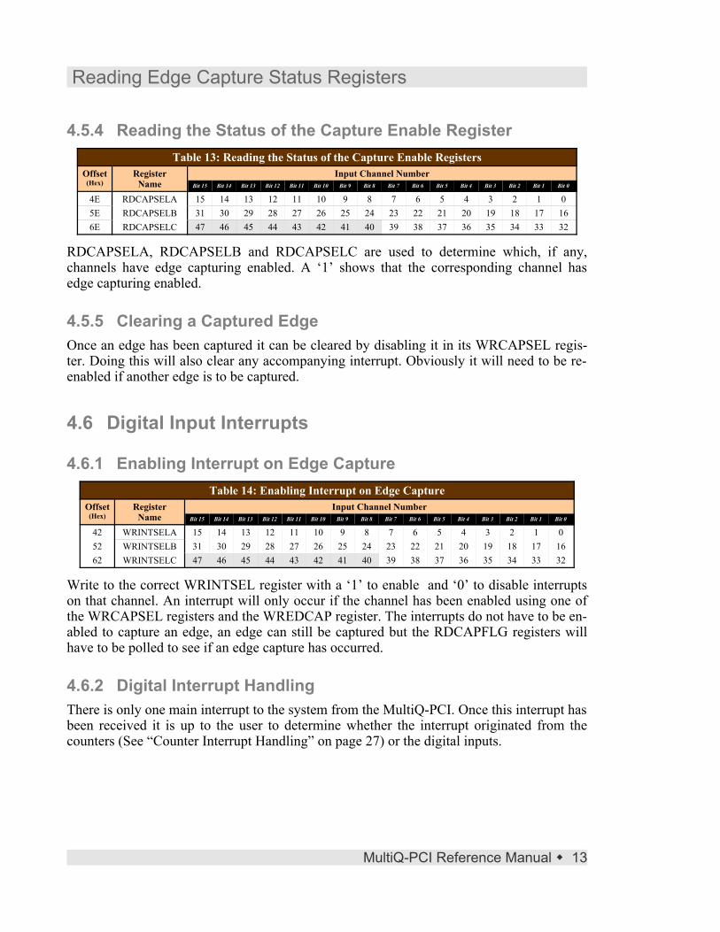
4.5.4 Reading the Status of the Capture Enable RegisterTable 13: Reading the Status of the Capture Enable Registers
Offset(Hex)
RegisterName
Input Channel NumberBit 15 Bit 14 Bit 13 Bit 12 Bit 11 Bit 10 Bit 9 Bit 8 Bit 7 Bit 6 Bit 5 Bit 4 Bit 3 Bit 2 Bit 1 Bit 0
4E RDCAPSELA 15 14 13 12 11 10 9 8 7 6 5 4 3 2 1 05E RDCAPSELB 31 30 29 28 27 26 25 24 23 22 21 20 19 18 17 166E RDCAPSELC 47 46 45 44 43 42 41 40 39 38 37 36 35 34 33 32
RDCAPSELA, RDCAPSELB and RDCAPSELC are used to determine which, if any,channels have edge capturing enabled. A ‘1’ shows that the corresponding channel hasedge capturing enabled.
4.5.5 Clearing a Captured EdgeOnce an edge has been captured it can be cleared by disabling it in its WRCAPSEL regis-ter. Doing this will also clear any accompanying interrupt. Obviously it will need to be re-enabled if another edge is to be captured.
4.6 Digital Input Interrupts
4.6.1 Enabling Interrupt on Edge CaptureTable 14: Enabling Interrupt on Edge Capture
Offset(Hex)
RegisterName
Input Channel NumberBit 15 Bit 14 Bit 13 Bit 12 Bit 11 Bit 10 Bit 9 Bit 8 Bit 7 Bit 6 Bit 5 Bit 4 Bit 3 Bit 2 Bit 1 Bit 0
42 WRINTSELA 15 14 13 12 11 10 9 8 7 6 5 4 3 2 1 052 WRINTSELB 31 30 29 28 27 26 25 24 23 22 21 20 19 18 17 1662 WRINTSELC 47 46 45 44 43 42 41 40 39 38 37 36 35 34 33 32
Write to the correct WRINTSEL register with a ‘1’ to enable and ‘0’ to disable interruptson that channel. An interrupt will only occur if the channel has been enabled using one ofthe WRCAPSEL registers and the WREDCAP register. The interrupts do not have to be en-abled to capture an edge, an edge can still be captured but the RDCAPFLG registers willhave to be polled to see if an edge capture has occurred.
4.6.2 Digital Interrupt HandlingThere is only one main interrupt to the system from the MultiQ-PCI. Once this interrupt hasbeen received it is up to the user to determine whether the interrupt originated from thecounters (See “Counter Interrupt Handling” on page 27) or the digital inputs.
MultiQ-PCI Reference Manual � 13

Digital Input Interrupts
The RDCAPFLG registers and the corresponding RDINTREG registers need to be logi-cally ‘AND-ed’ together to determine whether an interrupt occurred on a particular digitalinput channel.An interrupt must be cleared once it has been handled to prevent it from causing multipleinterrupts. (See “Clearing a Captured Edge” on page 13).
14 � MultiQ-PCI Reference Manual

Counters
5. Counters
5.1 OverviewThe MultiQ-PCI has six counters arranged in 3 pairs : 1A, 1B, 2A, 2B, 3A and 3B. One ofthese pairs is shown in Figure 7 on page 20. They can be used in pairs or “stand alone”.Each counter can be used with the internal quadrature encoder interface for positioning sys-tems, as timers using the internal clock, or as external (hardware) or internal (software)event counters. When paired, a 48 bit counter can be achieved and development of func-tions like frequency counting is easy, as one counter in the pair can feed the other countereither as a count, clear or latch input.The counter features include:
• Counters can be completely software driven.
• Counters can be driven from digital inputs 0-15.
• Counters can be driven from internal timers.
• Counters can be driven from encoder inputs.
• Encoder input buffers interface directly to TTL, CMOS, or differential RS422 signals.
• Quadrature decoder logic is available to detect and convert encoder edges into clockand direction signals.
• Encoder quadrature multiplier (x1, x2, x4)
• 24-bit up/down counters that can be pre-loaded by various triggers.
• Counters can be read on the fly or captured by various triggers to be read later.
• Selectable counter direction for timer and event counting modes.
• Index input or overflow count can re-load counter with preset values.
• Programmable interrupt on rollover or index pulse.
• 5 Volt encoder power is available at encoder connector.
5.1.1 LatchesFrom Figure 7 "Block diagram of a counter pair" it can be seen that there is one latch perpair of counters.
MultiQ-PCI Reference Manual � 15

Overview
Counter A or B can cause it’s own count to be latched on receiving an index pulse. Or, anoverflow from counter A can cause counter B’s count to be latched. These latches can beaccompanied with an interrupt and the value captured in the latch can be read later. The latches can also be setup to latch as they are read. This allows the present value of theselected counter to be read.
5.1.2 Clear/Pre-loadThe system can be programmed so that an overflow from Counter A will clear counter B.This is useful for frequency counting where counter B is latched & cleared at an intervaldetermined by the time it takes for counter A to overflow.Both counters can be programmed so that an index or overflow from a counter will pre-load itself with the contents of it’s pre-load register. This feature could be used to clear thecounter by loading it with 0. This feature would be used for setting up a programmable in-terval timer. Both the clear & pre-load can be accompanied by an interrupt.
5.1.3 InterruptsEach counter can generate an interrupt on overflow, index or both.
5.1.4 Overflow OutputsThe overflow output of each counter can be individually connected to a digital output.When the counter overflows a single pulse will occur pulling the output load low for 2clock cycles (500 nsec).
5.1.5 Index InputsEach counter has a hardware or software controlled index input that can programmed toperform clear, pre-load or latch functions. (See “Clear/Pre-load” and “Latches” above).
5.1.6 Counter InputsEach counter has various input modes including:
• Quadrature encoders with hardware or software controlled index.
• Single-ended event, direction and index inputs.
• System clock with hardware or software control of direction and index for event timing.
16 � MultiQ-PCI Reference Manual

Overview
Each counter channel has two clock input phases (referred to as channels in this manual)named “A” and “B”. Depending on the application, one or both of these signals may beconnected to an encoder or to a pulse source.If both phases are used, they are assumed to be quadrature encoded, meaning that they are90º out of phase. In this case, counters will count both up and down based on the timing re-lationship of the two-phase inputs.If only one phase is used, the input is said to be single-phase. In this case, counter channelswill count either up or down for each pulse on the phase input depending on the polarity ofthe direction input. This configuration is typically used to count pulses from devices thatproduce a single clock output.Quadrature encoders for positioning systems have advantages over single-phase encoders.Counters will not accumulate errors when an encoder changes direction or dithers about astate transition boundary. Also, it is possible to increase encoder resolution by clocking the counters at a multiple ofthe single-phase clock rate.
5.1.7 Power FailureIf an external NiCad battery is connected and fully charged and the Battery Enable bit ofMISC2 is set (see “Battery Backup” on page 35), then all the counter registers will be heldand the counters will continue to operate if power is lost, even though the rest of the systemis down.
The counter interrupts are disabled when the system powers up but if an in-terrupt occurred during power down then it will occur the moment the in-terrupts are re-enabled.
MultiQ-PCI Reference Manual � 17

Overview
5.1.8 Counter RegistersTable 15: Counter Registers
Write ReadOffset
(hex)RegisterName
Description
0 CR1A Counter 1A setup register2 CR1B Counter 1B setup register4 CR2A Counter 2A setup register6 CR2B Counter 2B setup register8 CR3A Counter 3A setup registerA CR3B Counter 3B setup registerC PRE1ALSW Pre-loads 1A lswE PRE1AMSW Pre-loads 1A msw10 PRE1BLSW Pre-loads 1B lsw12 PRE1BMSW Pre-loads 1B msw14 PRE2ALSW Pre-loads 2A lsw16 PRE2AMSW Pre-loads 2A msw18 PRE2BLSW Pre-loads 2B lsw1A PRE2BMSW Pre-loads 2B msw1C PRE3ALSW Pre-loads 3A lsw1E PRE3AMSW Pre-loads 3A msw20 PRE3BLSW Pre-loads 3B lsw22 PRE3BMSW Pre-loads 3B msw
Offset (hex)
RegisterName
Description
0 CR1A Counter 1A setup register2 CR1B Counter 1B setup register4 CR2A Counter 2A setup register6 CR2B Counter 2B setup register8 CR3A Counter 3A setup registerA CR3B Counter 3B setup registerC LATCH1ALSW Reads Latch 1A lswE LATCH1AMSW Reads Latch 1A msw10 LATCH1BLSW Reads Latch 1B lsw12 LATCH1BMSW Reads Latch 1B msw14 LATCH2ALSW Reads Latch 2A lsw16 LATCH2AMSW Reads Latch 2A msw18 LATCH2BLSW Reads Latch 2B lsw1A LATCH2BMSW Reads Latch 2B msw1C LATCH3ALSW Reads Latch 3A lsw1E LATCH3AMSW Reads Latch 3A msw20 LATCH3BLSW Reads Latch 3B lsw22 LATCH3BMSW Reads Latch 3B msw
5.2 Encoder Connections
Figure 4: Differential pair encoder Figure 5: Single-ended encoder Figure 6: Single-ended event counter withexternal count direction and index control.
(output with complement) (TTL or CMOS) (TTL or CMOS)
18 � MultiQ-PCI Reference Manual
Encoder
A
B
Index
Vcc
GND
MultiQ-PCIA+A-
B+B-
I+I-
+5V
GND
Device
Out
Vcc
GND
MultiQ-PCIA+A-
B+B-
I+I-
+5V
GND
2.5V
Direction(+5V=Up, 0V=Down)
Index
Encoder
A
B
Index
Vcc
GND
MultiQ-PCIA+A-
B+B-
I+I-
+5V
GND
2.5V

Encoder Connections
Note: If the counters are driven in a single-ended mode as shown in Figure 5 and Figure 6,then the unused phase inputs do not have to be biased at 2.5V. Each encoder input has two100K resistors that bias the input to 2.5V when no driving source is present.The encoders are also referred to by channel numbers. Counters map to channel numbersaccording to the following table:
Table 16: Encoder ChannelsCounter Encoder
1A 02A 13A 21B 32B 43B 5
MultiQ-PCI Reference Manual � 19

Block Diagram
5.3 Block Diagram
Figure 7: Block diagram of a counter pair
20 � MultiQ-PCI Reference Manual
Co
un
ter A
Co
un
ter B
Inpu
t log&
Mu
ltiplie
Encod
er
Digital I/O
Intern
al clock
So
ftware con
t
Inpu
t log&
Mu
ltiplie
Encod
er
Digital I/O
Intern
al clock
So
ftware con
tr
Coun
t
Directio
n
Index
Pre-L
oad
regA
Pre-L
oad
regB
P C I B u s
Coun
t A
Ov
erflow
Ov
erflow
A
Co
un
ter B
Co
un
ter B
Clear/P
re-loa
Coun
t
Directio
n
Index
Coun
t B
Latch
1
Inpu
t A
Inpu
t B
Latch A
Clear/P
re-loa
Ov
erfloIn
terrup
Cap
tur
Reg
isteB
Interru
pC
aptu
rR
egiste
A
C o m bine d C oun te r Int er rupt s
F ro mothe rc oun te ri nt er rupt s
F ro mothe rc oun te ri nt er rupt s
Latch B

Programming the Counters
5.4 Programming the CountersTable 17: CR1A 00 (hex) Read/Write
Bit 15 Bit 14 Bit 13 Bit 12 Bit 11 Bit 10 Bit 9 Bit 8 Bit 7Counter B index source Counter B source Counter A Index edge selection Counter A pre-load trigger source Counter A multiplier00=Encoder01=Digital inputs10=Controlled by bit 1
of CR1B11=Index disabled
00=Encoder01=Digital inputs10=Up Count with System clock 11=Down count with System clock(10 & 11 gated by bit 1 of CR1B)
0=Positive1=Negative
(Also used for software controlof Counter A Index, 1=index)
00=Counter A index pulse01=Counter A overflow10=Disabled11=Disabled
00=4x01=2x10=1x11=Channel A is direction.
Index is count pulse
Bit 6 Bit 5 Bit 4 Bit 3 Bit 2 Bit 1 Bit 0Counter A interrupt source Counter A source edge selection Counter A Index source Counter A source00=None 01=Overflow only10=Index only11=Index & Overflow
0=Positive1=Negative(Also software control of Counter A count pulse.1=enable when running with the system clock)
00=Encoder01=Digital inputs10= Controlled by CR1A bit1111= Index disabled
00=Encoder01=Digital inputs10=System clock up (gated by bit4)11=System clock down (gated by bit4)
Table 18: CR1B 02 (hex) Read/WriteBit 15 Bit 14 Bit 13 Bit 12 Bit 11 Bit 10 Bit 9 Bit 8
Clear Interrupt Select Interrupt B Select interrupt A Counter A Enable Counter B interrupt source Latch source
1=ClearUsed with bit 13 or 14
1=SelectedUsed with bit 15
1=SelectedUsed with bit 15
0=Enabled1=Only enabled if index A is high
00=None 01=Overflow only10=Index only11=Index & Overflow
00=Depends on latch read address01=A’s index latches A10=B’s index latches B11=Counter A overflow capturesB
Bit 7 Bit 6 Bit 5 Bit 4 Bit 3 Bit 2 Bit 1 Bit 0Counter B pre-load triggersource
Clear Counter B Counter B multiplier Counter B Enable Counter B index edgeselection
Counter B source edge selection
00=Counter B indexpulse
01=Counter B overflow10=Counter A overflow11=Disabled
1=Counter Aoverflow clearsCounter B
0=Not Cleared
00=4x01=2x10=1x11=Channel A is direction(Counter A overflow iscount pulse)
0=Enabled1=Only enabled if
index B is high
0=Positive1=Negative(Also software controlof Counter B Index,1=index)
0=Positive1=Negative(Also software control of CounterB count pulse. 1=enable whenrunning with the system clock)
The grayed bits read back different information to that which was written to them. (See Table 19 "CR1B 02 (hex) Read" below).
Table 19: CR1B 02 (hex) ReadBit 15 Bit 14 Bit 13
Counter BDirection0=Down1=Up
1=Counter Aoverflow routed todigital output
1=Counter Boverflow routedto digital output
In the following examples groups of bits will be referred to using their name and set to a bi-nary value. For example ‘Counter B Multiplier’=10 means bit 4 =1 and bit 3=0.‘X’ is used to show the value of a bit in one of the counter registers that is not important tothe example being discussed. This is not to say it should be ignored. The value of these bitswill depend on other functions being used and writing to any bit in the configuration exam-ple will always have an effect. Some bits have dual functions depending on the present set-tings of other bits.Many of the counter examples will only deal with counter 1A. Unless otherwise stated thefunction being discussed can also be applied to counter 1B. The correct register & bit/s just
MultiQ-PCI Reference Manual � 21
Counters 2 and 3 have the same register layout but with differentRead/Write addresses (see Table 15 "Counter Registers" on page 18).

Programming the Counters
need to be used by looking at the applicable tables. Counters 2A, 2B, 3A and 3B will func-tion in the same way just controlled using different register addresses.Do not be confused by the naming of registers CR1A and CR1B. They are simply the Aand B parts of the single register CR1 (Counter Register 1) and do not refer specifically tocounter A and counter B.
5.5 Configuring the Counter SourceCounter A and Counter B can be driven by a differential or single-ended encoder, the digi-tal inputs, software or from the system clock. Each counter’s input logic has a count, direc-tion and index line that may be controlled.The ‘Counter A Source’ bits are used to select counter A’s source (see Table 17 and 18 onpage 21):� If ‘Counter A Source’ is 00 then encoder inputs are selected.
� If ‘Counter A Source’ is 01 then the digital inputs control the counters.
Table 20: Digital inputs as Counter input controlsDigital Input Channel Counter Counter Input Function
0 1 A Count or direction input1 1 A Count input2 1 A Index input3 1 B Count or direction input4 1 B Count input5 1 B Index input6 2 A Count or direction input7 2 A Count input8 2 A Index input9 2 B Count or direction input
10 2 B Count input11 2 B Index input12 3 A Count or direction input13 3 A Count input14 3 A Index input15 3 B Count or direction input16 3 B Count input17 3 B Index input
When the digital inputs are selected as the source then the corresponding digital inputs canbe used to control the counters in much the same way as when the encoder inputs are used.(See Table 20 “Digital inputs as Counter input controls” above). This mode also gives soft-ware control of the counters. This is achieved by writing to the corresponding digital outputwhich in turn changes the digital input and thus the counter. The disadvantage to this tech-
22 � MultiQ-PCI Reference Manual

Configuring the Counter Source
nique is the fact that the digital output is now used for counter control and cannot be usedfor normal I/O functions.In mode 00 and 10 above, the ‘Counter A Source Edge Selection’ is used to select positive‘0’ or negative ‘1’ edge selection:� If ‘Counter A Source’ is 10 then the counter will count down with the system clock.
� If ‘Counter A Source’ is 11 then the counter will count up with the system clock.
In both these modes the ‘Counter A Multiplier’ must be 10 and ‘Counter A Source EdgeSelection’ must be 1. These two bits become part of the oscillator feedback loop. ‘CounterA Source Edge Selection’ may be used as an enable. The timer will only run when it is ’1’.‘Counter A Enable’ is used to gate the counter under normal counting operation. Whencleared, counting is enabled. when set counting is disabled. When using software to controlcounter A, ‘Counter A Enable’ must be ‘1’ to enable counting.The ‘Counter A Index Source’ bits are used to select counter A’s index source:� If ‘Counter A Index Source’ is 00 then the encoder index input will control indexing.
� If ‘Counter A Index Source’ is 01 then the digital inputs control the indexing. While inthis mode, ‘Counter A Index Edge Selection’ = 0 will index on the positive edges while1 will index on the negative edges.
5.5.1 Software Control of the Index PulseIf ‘Counter A Index Source’ is 10 or 11 then an index is caused by toggling the ‘Counter AIndex Edge Selection’ bit. When this kind of software control of the index pulse is neededit is recommended that the ‘Counter A Index Source’ be set to 10. Then setting ‘Counter AIndex Edge Selection’ will set the index input to the counter and clearing it will clear theindex input to the counter. If the ‘Counter A Index Source’ be set to 11 then setting‘Counter A Index Edge Selection’ will clear the index input to the counter and clearing itwill set the index input to the counter.
5.5.2 MultiplierThe ‘Counter A Multiplier’ bits are used to multiply counter A’s incoming pulses by 1, 2 or4 or to allow software count control.The ‘Counter B Multiplier’ bits are used to multiply counter B’s incoming pulses by 1, 2 or4 or to allow an overflow from counter A to cause counter B to count 1.The multiplying feature is only used when the encoder or digital inputs are used to drive thecounters. If only a count and direction input is being used then the multiplier should be 1xor 2x. Channel A is the direction and channel B the count.
MultiQ-PCI Reference Manual � 23

Configuring the Counter Source
5.5.3 Software Control of Direction and Count GenerationThis mode is only available on counter A. Direction control and a count pulse can be gener-ated completely under software control for counter A. This mode uses the counter's indexinterface to generate the count pulse. As a result, while in this mode, the index cannot causean interrupt, a latch or a pre-load of counter A. To place counter A in this mode ‘Counter AEnable’ must be 1 and ‘Counter A Multiplier’ must be 11.When counters A and B are paired, the count direction is determined by counter A. Thecount direction may be controlled by the channel A encoder inputs, the channel A digitalinputs or can be software controlled. To use software control for the direction, ‘Counter AEdge Selection’ must be 0. To set the count direction down ‘Counter A Source’ must be 10.To set the count direction up ‘Counter A Source’ must be 11. When using the encoder ordigital inputs, channels A and B must be connected in parallel to form a single directioncontrol. The index channel of counter A controls counting. It can be connected using the encoderindex channel, the digital input index pin or it can be software controlled. To use softwarecontrol for the count pulse, it is recommended that the ‘Counter A Index Source’ be set to10. In this case, setting ‘Counter A Index Edge Selection’ will set the index input and thenclearing it will clear the index input, thus creating a count pulse. If the ‘Counter A IndexSource’ is set to 11 then setting ‘Counter A Index Edge Selection’ will clear the index inputand clearing it will set the index input, also creating a count.
5.6 Driving Counter B from Counter A's OverflowThis mode is only available on Counter B. Counter B can be setup so that it will countevery time counter A overflows. To do this ‘Counter B Multiplier’ must be 11, which willcause the count input to counter B to come from counter A’s overflow. Channel A of counter B will now control the count direction. It can be connected to thechannel A encoder input, the channel A digital input or it can be software controlled. Touse software control for the direction, ‘Counter B Source Edge Selection’ must be 0. To setthe count direction to down ‘Counter B Source’ must be 11. To set the count direction to up‘Counter B Source’ must be 10.
5.7 Triggering a Counter LoadEach counter has a pre-load register that can be loaded into the counter when triggered byvarious events. Each counters pre-load register is set up by simply writing the 24 bit valueto the lsb and msb of the pre-load register (see Table 15 “Counter Registers" on page 18).
24 � MultiQ-PCI Reference Manual

Triggering a Counter Load
Pre-loading counter A can be triggered by an index pulse or overflow of counter A. Pre-loading counter B can be triggered by an index pulse or an overflow of counter A or B. Aload must not be set to be triggered from counter A’s index if the index is being used to runthe counter under software control. Doing so will cause a load every time counter A counts(see ‘Counter A & B Pre-Load Trigger Source’ in Table 17 and 18 on page 21).
5.8 Clearing Counter B from Counter A's OverflowSetting ‘Clear Counter B’ to 1 will allow an overflow from counter A to clear counter B.This is only available for counter B. Of course the same effect could be achieved by pre-loading the counter with 0.
5.9 Latching the CountersEach pair of counters 1, 2 and 3 has one latch between them. (See Figure 7 “Block diagramof a counter pair” on page 20). There are two distinct sets of modes of operation for thelatches. Mode 1: ‘Latch Source’ = 00 allows either counter A or counter B to be captured any time.
The least significant word (lsw) must be read first. This causes the entire 24 bitcount to be latched allowing the most significant word (msw) to be read laterwithout causing the count to be re-latched. The read address will decide whichcounter will be latched (see Table 15 “Counter Registers” on page 18 for the readaddresses).
Mode 2: In the second set of modes the appropriate counter is latched by an event thatwould usually be programmed to also create an interrupt. This interrupt thenprompts the user to read the latched count before it is overwritten by the nextevent. To read the count the lsw and msw of either latch A or B for the appropri-ate counter can be read (see Table 15 “Counter Registers” on page 18 for the readaddresses). In this mode it does not matter which order the lsw & msw are read asthey will have already been latched.‘Latch Source’ = 01 will latch counter A when there is a counter A index.‘Latch Source’ = 10 will latch counter B when there is a counter B index.‘Latch Source’ = 11 will latch counter B when counter A overflows (useful when
frequency counting).
MultiQ-PCI Reference Manual � 25

Interrupts
5.10 Interrupts
5.10.1 Interrupts While Under Battery BackupIf there is a power failure while an external NiCad battery is connected and fully chargedand the ‘Battery Enable’ bit of MISC2 was set (See Table 23 “Write to MISC2 90 (hex)”on page 31) then when power is restored the interrupts are automatically disabled. Any in-terrupts that occurred while the power was down will cause an interrupt the moment inter-rupts are re-enabled.
5.10.2 Interrupt Source SelectionIf ‘Counter A (or B) Interrupt Source’ = 00 then no interrupt will occur. An index and/or anoverflow can still be captured but they will not generate an interrupt. The MISC2 registerwill have to be polled to see if an index or overflow has occurred.If ‘Counter A (or B) Interrupt Source’ = 01 then an interrupt will occur when the counteroverflows. If ‘Counter A (or B) Interrupt Source’ = 10 then an interrupt will occur when the counterreceives an index pulse.When ‘Counter A (or B) Interrupt Source’ = 11 then an interrupt will occur when the coun-ter overflows or receives an index.
5.10.3 Clearing an InterruptThere are 3 bits per counter pair that are used to clear the interrupts. . The ‘Select InterruptA or B’ bits (bit 13 & 14) are used to select which interrupts must be cleared. A ‘1’ in ei-ther register will allow it to be cleared. Then writing a ‘1’ to the ‘Clear Interrupt’ will clearthe interrupts selected with a ‘1’ in their ‘Select Interrupt A or B’ bit. If the ‘Clear Inter-rupt’ bit is clear it has no effect.
26 � MultiQ-PCI Reference Manual
void clearInterrupt2A(){
// A '1' is written to interrupt A to select it and a '1' is written to the// interrupt command bit to clear interrupt AWriteReg(board, 0x06, 0b101XXXXXXXXXXXXX);
}
Example 2: Clearing an interrupt on Counter 2A

Interrupts
5.10.4 Counter Interrupt HandlingThere is only one main interrupt to the system from the MultiQ-PCI. Once this interrupt hasbeen received it is up to the user to determine whether it originated from the counters or thedigital inputs. (See “Digital Interrupt Handling” on page 13).The ‘Counter Overflow Interrupt’ flags (COINT) and the ‘Index interrupt’ flags (INDINT)of the MISC2 register (See Table 24 “Read from MISC2 92 (hex)” on page 31) must bechecked to determine which counter and what event may have caused the interrupt. An in-terrupt must be cleared once it has been handled to prevent it from causing multiple inter-rupts. (See “Clearing an Interrupt” on page 26).
5.11 Counter Configuration Examples
5.11.1 Setup Counter 1A and 1B to Count Frequency at 1BIn this example Counter 1A is set up to count down using the system clock which willcause the counter to count at 2MHz (1 count takes 500nsec). Pre-loading counter 1A withtwo million will have the counter count for exactly 1 second before it overflows. When itoverflows it is set up to pre-load itself again, thus generating an overflow every second.
MultiQ-PCI Reference Manual � 27
void clearInterrupt2B(){
// A '1' is written to interrupt B to select it and a '1' is written to the// interrupt command bit to clear interrupt AWriteReg(board, 0x06, 0b110XXXXXXXXXXXXX);
}
Example 3: Clearing an interrupt on Counter 2B
void clearInterrupt3A3B(){
// A '1' is written to interrupt A and B to select them and a '1' is written to the// interrupt command bit to clear interrupt AWriteReg(board, 0x0a, 0b111XXXXXXXXXXXXX);
}
Example 4: Clearing an interrupt on Counter 3A and 3B

Counter Configuration Examples
Counter 1B is set up to count the unknown frequency from an external source. The over-flow from Counter 1A is set to first latch Counter 1B’s count and then clear the count. Thiswill occur every second. The value held in the latch is the number of counts that Counter1B counted is 1 second which is a direct frequency reading (Hz - Cycles per second). Thisvalue can be read by the system at any time.
28 � MultiQ-PCI Reference Manual
Figure 8: Frequency counter block diagram and timing
Pre-load A(used to setup t ime base)
Counter AFixed internal
clock reference
MeasuredFrequency Latch B Read by system
Overflow
Counter B
Overflow
Clear
A Overflow (1)
B Count (2)
Latch B (3)
Clear B (4)
Pre-load A (5)
5
1
4
3
2

Counter Configuration Examples
MultiQ-PCI Reference Manual � 29
void setupFrequencyCounting(){
// Pre-load 1A with lsw of 2000000WriteReg(board, 0x0C, 0x8480);
// Pre-load 1A with msw of 2000000WriteReg(board, 0x0D, 0x001E);
// Setup counter's CR1AWriteReg(board, 0x00, 0x0373);
// Setup counter's CR1BWriteReg(board, 0x02, 0xfff0);
// The counters are now set up and running
// To read the frequency in Hertz, tead the Latched value of counter 1B// as follows:
lsw = ReadReg(board, 0x10); // Get the lsw of the frequencymsw = ReadReg(board, 0x12); // Get the msw of the frequency
}
Example 5: Frequency counter


Watchdog/Miscellaneous Registers
6. Watchdog/Miscellaneous Registers
Table 21: Write to MISC1 88 (hex)Bit 15 Bit 14 Bit 13 Bit 12 Bit 11 Bit 10 Bit 9 Bit 8
1=Writeenable
Not used Not used EDCAP(see pg. 10)
Not UsedISEL4 (not ISEL3 )
Not UsedISEL2
Not UsedISEL1
Not Used ISEL0
Bit 7 Bit 6 Bit 5 Bit 4 Bit 3 Bit 2 Bit 1 Bit 0
Not UsedGSEL3
Not UsedGSEL2
Not UsedGSEL1
Not UsedGSEL0
Not UsedDACPOL3
Not UsedDACPOL2
Not UsedDACPOL1
Not UsedDACPOL0
Table 22: Read from MISC1 88 (hex)Bit 15 Bit 14 Bit 13 Bit 12 Bit 11 Bit 10 Bit 9 Bit 8
1=WriteEnabled
1=Watchdogtimed out
InternalRegisterDAC_EN
EDCAP(see pg. 10)
Internal RegisterISEL4 (not ISEL3)
InternalRegisterISEL2
InternalRegisterISEL1
InternalRegisterISEL0
Bit 7 Bit 6 Bit 5 Bit 4 Bit 3 Bit 2 Bit 1 Bit 0
InternalRegisterGSEL3
InternalRegisterGSEL2
InternalRegisterGSEL1
InternalRegisterGSEL0
Internal RegisterDACPOL3
InternalRegisterDACPOL2
InternalRegisterDACPOL1
InternalRegisterDACPOL0
Table 23: Write to MISC2 90 (hex)Bit 15 Bit 14 Bit 13 Bit 12 Bit 11 Bit 10 Bit 9 Bit 8
1=Clearwatchdog
1=ChargeEnable
Not used Not used Not used Not used 0=Digitaloutput 6
0=Digitaloutput 5
1=Counter 6Overflow
1=Counter 5Overflow
Bit 7 Bit 6 Bit 5 Bit 4 Bit 3 Bit 2 Bit 1 Bit 0
0=Digitaloutput 4
0=Digitaloutput 3
0=Digitaloutput 2
0=Digitaloutput 1
1=BackupBatteryEnabled
1=WatchdogEnabled
Watchdog period selection00=1/8
th second01=½ second10=1 second11=10 seconds
1= Counter 4Overflow
1= Counter 3Overflow
1= Counter 2Overflow
1= Counter 1Overflow
Table 24: Read from MISC2 92 (hex)Bit 15 Bit 14 Bit 13 Bit 12 Bit 11 Bit 10 Bit 9 Bit 8
COINT3B COINT3A COINT2B COINT2A COINT1B COINT1A INDINT3B INDINT3A
Bit 7 Bit 6 Bit 5 Bit 4 Bit 3 Bit 2 Bit 1 Bit 0
INDINT2B INDINT2A INDINT1B INDINT1A 1=BackupBatteryEnabled
1=Watchdogenabled
Watchdog period selection00=1/8
th second01=½ second10=1 second11=10 seconds
The grayed bits do not read back the same registers.
MultiQ-PCI Reference Manual � 31

Battery Charging
6.1 Battery ChargingBit 14 “Charge Enable” of MISC2 (92 hex) turns the trickle charging of an optional exter-nal backup battery on and off. The system will default to “Charging off” after a reset.Before writing to any of the bits of MISC2, except bit 15 (Clear watchdog), the write en-able (bit 15) of MISC1 must be set. This is to prevent accidental modification of the watch-dog settings by a crashed CPU. It is a good idea to clear this bit immediately after writingto MISC2.
6.2 Watchdog Oscillator
6.2.1 OverviewEmbedded systems often include a watchdog timer to regain program control following anunplanned loss of control by the PCI bus master. In such systems, the CPU is responsiblefor periodically clearing the watchdog timer. Should the CPU crash, the watchdog won't becleared and will eventually overflow and cause the CPU to be reset through the PCI bus.After a reset the watchdog timer is disabled and the watchdog oscillator selection is cleared.To use the watchdog, it needs to be enabled and the watchdog period needs to be set.
6.2.2 Testing the Watchdog Without Resetting the HostUnder normal conditions a watchdog time-out will cause the PCI bus to be reset. By re-moving jumper JP1 no PCI reset will occur although the watchdog will be fully functionalinternally. This may be useful during development as the status of the watchdog can be ob-tained from bit 14 of Misc1. A ‘1’ means it has timed out. The watchdog output at JP1 is an‘open collector’ output.
6.2.3 Watchdog Enable and Period SelectionBits 1 and 0 of MISC2 (92 hex) are used to select a period of 1/8th, ½, 1 or 10 seconds whilebit 2 is used to enable the watchdog (see Table 23 “Write to MISC2 90 (hex)” on page 31).Before writing to any of the bits of MISC2, except bit 15 (clear watchdog), the write enable(bit 15) of MISC1 must be set. This is to prevent accidental modification of the watchdogsettings by a crashed CPU. It is a good idea to clear this bit immediately after writing toMISC2.Although the Enable and period selection bits are in the same register, first the registermust be written to with the ‘Watchdog Enable’ bit = ‘1’ (bit 2) and then the register must
32 � MultiQ-PCI Reference Manual

Watchdog Oscillator
be written to again with bit 2 again = ‘1’ and the period selection bits set as desired. This isbecause the period selection bits are held in a cleared state (1/8th of a second) and cannot bechanged until the ‘Watchdog enable’ bit is = ‘1’.
6.2.4 Clearing the WatchdogTo prevent a PCI reset the watchdog timer must be cleared at least once within the periodof the watchdog timer. To do this bit 15 (“Write Enable”) of MISC1 (88 hex) must first becleared and then bit 15 (Clear watchdog) of MISC2 (92 hex) must be set. The clear watch-dog bit is automatically cleared after the watchdog has been cleared.
6.2.5 Watchdog LED StatusIf the watchdog is disabled the red LED will be off continuously.When the watchdog is enabled the LED will be off for ½ the selected watchdog period,then on for ½ the period and then the watchdog will reset the PCI bus (pulled low) if JP1 isinserted. If the jumper is not inserted then bit 14 of MISC2 will go high and the LED willflash at ½ the selected watchdog period.
6.3 Digital Outputs 0-5 Source SelectionBits 4-9 of MISC2 (90 hex) are used to select the function of digital outputs 0-5. They canbe setup either as standard digital outputs or to pull the output load low for a short pulsewhen the corresponding counter overflows (see Table 23 “Write to MISC2 90 (hex)” onpage 31).Before writing to any of the bits of MISC2, except bit 15 (clear watchdog), the write enable(bit 15) of MISC1 must be set. This is to prevent accidental modification of the watchdogsettings by a crashed CPU. It is a good idea to clear this bit immediately after writing toMISC2.MISC2 can not be used to read back the value that bits 4-9 were previously set to. This hasto be done by reading the Counter Register B of each counter as shown below.
Table 25: Reading back Digital Outputs 0-5 Source SelectionRegister Bit Digital I/O PIN FunctionCR1B (02 Hex) 14 0 0=Digital input, 1= Counter 1A Overflow
13 1 0=Digital input, 1= Counter 1B OverflowCR2B (06 Hex) 14 2 0=Digital input, 1= Counter 2A Overflow
13 3 0=Digital input, 1= Counter 2B OverflowCR3B (0A Hex) 14 4 0=Digital input, 1= Counter 3A Overflow
13 5 0=Digital input, 1= Counter 3B Overflow
MultiQ-PCI Reference Manual � 33


Battery Backup
7. Battery BackupA 3.6V Nickel Cadmium battery can be connected to the MultiQ-PCI using JP1. Make surethat it is connected correctly or damage will occur (see Figure 1 “MultiQ-PCI Data Acqui-sition Card” on page 2). It will be trickle charged at approximately 100mA if the “ChargeEnable” bit of MISC2 is set (see "Battery Charging" on page 32).While the backup battery is connected & charged the system clock can be made to run dur-ing a power failure to ensure that the counters do not loose counts. To do this the “BatteryEnable” bit of MISC2 must be set to enable the backup battery. In this state the countersetup registers and the count that the counter were at when the power failed will be heldand the counters will continue to count so no counts will be lost. If a counter interrupt oc-curs during backup (like a counter overflow) then the appropriate interrupt register will beset (counter overflow or index) but the interrupt enable is cleared when the main power tothe system is restored and the system is booted. This is done to allow the user time to ini-tialize everything. The moment the interrupts are re-enabled, the interrupt will be passed onto the system.
MultiQ-PCI Reference Manual � 35


Analog Inputs
8. Analog InputsThere are 16 analogue input channels (0-15). Each channel can be set to have a ±5V or±10V range which will return a 16 bit value (including the sign) in the range ±32767.A ‘Poll List’ is used to setup the A/D converter. This is a list containing 1-16 commandsthat will be executed sequentially every time the ReadADC command is used. Each com-mand tells the converter which channel to convert (0-15) and what range to use (±5V or±10V). The converter starts with the first command in the list and continues until it reachesa command with a ‘1’ in bit 15 of the command or until the 16th command is executed. Theresults are placed in the array Data[0..15]. If the same set of channel and range combina-tions need to be read again the user needs only to execute another ReadADC command andthe old Data will be overwritten with the new. When a new poll list needs to be set up, theCloseADC command needs to be executed to close the old list and then the ResetADCneeds to be executed with the details of the new poll list. This poll list approach makesreading several channels much faster (see "MultiQ-PCI Programming Guide").
Conversion takes approximately 23 µsec/channel. Once completely finished with the ADCthe CloseADC command should be executed.
MultiQ-PCI Reference Manual � 37


Analog Outputs
9. Analog OutputsThe analogue channels have a 14 bit resolution (including sign).
It takes approximately 11 µsecs to convert the digital value to an analogue output voltage.To use the Digital to Analogue converter call the WriteDAC function and supply a channeland an output value between –8191 and +8191. This will be converted to an analogue volt-age between ±10V at the specified output channel (see "MultiQ-PCI Programming Guide").Each D/A has a sense input that should be connected to the D/A output at the end of thewire used to connect to whatever external circuit is used with the D/A. This will help keepnoise down.If this feature is not used then insert the jumpers to connect the sense input to the D/A out-put right on the board.J6, J7, J8 and J9 are inserted to disable the D/A sense inputs for channels 0 -3 respectively.
MultiQ-PCI Reference Manual � 39


Appendix A: Specifications
Appendix A: SpecificationsTable 26: General Specifications
Interface Parameter Description
Bus Type PCI, 32-bit, 33MHz
Watchdog Output characteristics Open collector
Time-out options 1/8, ½, 1 and 10 seconds
Encoders Input characteristics Differential pair, TTL/CMOS compatible
Counter width 24 bits
Number of channels 6
Digital I/O Input characteristics TTL/CMOS compatible
Configuration Each channel is programmable as an input or output
Number of channels 48
A/D Resolution 14 bits
Input range Each channel is programmable as ±5V or ±10V
Number of channels 16
Conversion time Approximately (17+23n) µs, where n = # channels read
D/A Resolution 13 bits
Output range ±10V
Number of channels 4
Conversion time Approximately 17 µs/channel
Battery Type 3.6V Nickel Cadmium rechargeable (optional)
Charge current 62.5 mA
MultiQ-PCI Reference Manual � 41


Appendix B: Operating Limits
Appendix B: Operating LimitsTable 27: Operating Limits
Interface Parameter Min. Typical Max. Units
Power Operating range 4.75 5.25 V
Operating range +12V -11.6 15 V
Operating range -12V -15 -11.6 V
Quiescent current (not charging) 450 mA
Battery Charging current 0 50 62.5 mA
Battery drain under backup 60 mA
Battery drain with charger off and notin backup mode 5
mA
I/O Output sink current 100 mA
Captured pulse width 250 ns
Encoder Internal timer mode 2 Mhz
Externally driven 0 500 kHz
Watchdog Maximum current sink 500 mA
Temperature Operating range 0 70 C
MultiQ-PCI Reference Manual � 43

Appendix C: Analog Connector
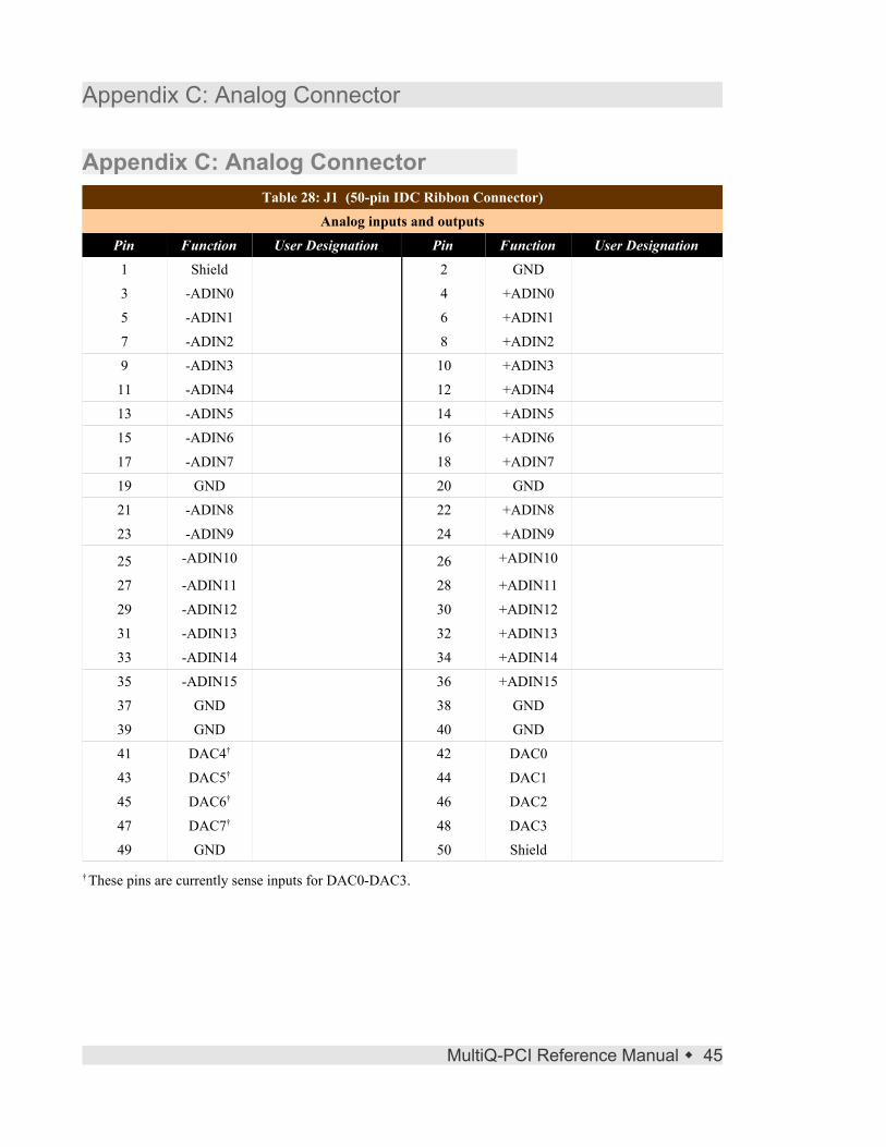
Appendix C: Analog ConnectorTable 28: J1 (50-pin IDC Ribbon Connector)
Analog inputs and outputsPin Function User Designation Pin Function User Designation
1 Shield 2 GND
3 -ADIN0 4 +ADIN0
5 -ADIN1 6 +ADIN1
7 -ADIN2 8 +ADIN2
9 -ADIN3 10 +ADIN3
11 -ADIN4 12 +ADIN4
13 -ADIN5 14 +ADIN5
15 -ADIN6 16 +ADIN6
17 -ADIN7 18 +ADIN7
19 GND 20 GND
21 -ADIN8 22 +ADIN8
23 -ADIN9 24 +ADIN9
25 -ADIN10 26 +ADIN10
27 -ADIN11 28 +ADIN11
29 -ADIN12 30 +ADIN12
31 -ADIN13 32 +ADIN13
33 -ADIN14 34 +ADIN14
35 -ADIN15 36 +ADIN15
37 GND 38 GND
39 GND 40 GND
41 DAC4† 42 DAC0
43 DAC5† 44 DAC1
45 DAC6† 46 DAC2
47 DAC7† 48 DAC3
49 GND 50 Shield
† These pins are currently sense inputs for DAC0-DAC3.
MultiQ-PCI Reference Manual � 45


Appendix D: Digital Connectors
Appendix D: Digital ConnectorsTable 29: J2 (50-pin IDC Ribbon Connector)
Digital I/O 0 - 23Pin Function User Designation
1 DIO23
3 DIO22
5 DIO21
7 DIO20
9 DIO19
11 DIO18
13 DIO17
15 DIO16
17 DIO15
19 DIO14
21 DIO13
23 DIO12
25 DIO11
27 DIO10
29 DIO9
31 DIO8
33 DIO7
35 DIO6
37 DIO5
39 DIO4
41 DIO3
43 DIO2
45 DIO1
47 DIO0
49 5V
Even pins GND
Table 30: J3 (50-pin IDC Ribbon Connector)Digital I/O 24 - 47
Pin Function User Designation1 DIO47
3 DIO46
5 DIO45
7 DIO44
9 DIO43
11 DIO42
13 DIO41
15 DIO40
17 DIO39
19 DIO38
21 DIO37
23 DIO36
25 DIO35
27 DIO34
29 DIO33
31 DIO32
33 DIO31
35 DIO30
37 DIO29
39 DIO28
41 DIO27
43 DIO26
45 DIO25
47 DIO24
49 5V
Even pins GND
MultiQ-PCI Reference Manual � 47


Appendix E: Encoder Connectors
Appendix E: Encoder ConnectorsTable 31: J4 (26-pin IDC Ribbon Connector)
Encoders 3-5Pin Function User Designation Pin Function User Designation
1 ENCD3 B- 2 ENCD3 B+3 GND 4 ENCD3 A-5 ENCD3 A+ 6 5V7 ENCD3 I- 8 ENCD3 I+9 GND 10 ENCD4 A-11 ENCD4 A+ 12 5V13 ENCD4 B- 14 ENCD4 B+15 GND 16 ENCD4 I-17 ENCD4 I+ 18 5V19 ENCD5 B- 20 ENCD5 B+21 GND 22 ENCD5 A-23 ENCD5 A+ 24 5V25 ENCD5 I- 26 ENCD5 I+
Table 32: J5 (26-pin IDC Ribbon Connector)Encoders 0-2
Pin Function User Designation Pin Function User Designation1 ENCD0 B- 2 ENCD0 B+3 GND 4 ENCD0 A-5 ENCD0 A+ 6 5V7 ENCD0 I- 8 ENCD0 I+9 GND 10 ENCD1 A-11 ENCD1 A+ 12 5V13 ENCD1 B- 14 ENCD1 B+15 GND 16 ENCD1 I-17 ENCD1 I+ 18 5V19 ENCD2 B- 20 ENCD2 B+21 GND 22 ENCD2 A-23 ENCD2 A+ 24 5V25 ENCD2 I- 26 ENCD2 I+
MultiQ-PCI Reference Manual � 49

Appendix E: Encoder Connectors
50 � MultiQ-PCI Reference Manual

Index
Stichwortverzeichnis
AAnalog input.................................................................................................................1, 37, 45Analog Output....................................................................................................................1, 39
BBattery Backup.........................................................................................................1, 3, 26, 35bias.........................................................................................................................................19
Ccircuit board.............................................................................................................................2CMOS........................................................................................................................15, 18, 41COINT..............................................................................................................................27, 31Connectors....................................................................................................................3, 47, 49count direction..................................................................................................................18, 24counter direction.....................................................................................................................15counter overflow................................................................................1, 5, 9, 16, 26, 27, 33, 35CR1......................................................................................................................18, 21, 22, 33
DD/A sense...........................................................................................................................3, 39Digital I/O....................................................................................................1, 3, 5, 7, 8, 33, 41Digital input.............................................................................1, 5, 8-10, 13-15, 21-24, 27, 33Digital Output...........................................................................................1, 8, 9, 16, 21-23, 33
EEDCAP...................................................................................................................5, 10, 13, 31edge detection...................................................................................................................1, 5, 7Encoder........................................................................................1, 3, 15-19, 21-24, 41, 43, 49
Iindex pulse...........................................................................................1, 15, 16, 21, 23, 25, 26INDINT............................................................................................................................27, 31
JJP1..........................................................................................................................3, 32, 33, 35jumpers...............................................................................................................................3, 39
LLatch Source.....................................................................................................................21, 25loopback...................................................................................................................................3
MMISC1.....................................................................................................................5, 10, 31-33MISC2...................................................................................................5, 17, 26, 27, 31-33, 35MultiQ-PCI data acquisition card............................................................................................2
NNiCad battery...................................................................................................................17, 26
Ooverflow.............................................................................1, 5, 9, 15, 16, 21, 23-28, 31-33, 35
PPCI bus.........................................................................................................................1, 32, 33plug-and-play...........................................................................................................................1power failure......................................................................................................1, 5, 17, 26, 35pre-load......................................................................................1, 5, 15, 16, 18, 21, 24, 25, 27pull-up resistor.....................................................................................................................7, 9

Index
QQuadrature........................................................................................................................15-17
RRDCAPFLG............................................................................................................8, 10, 12-14RDCAPSEL.......................................................................................................................8, 13RDEDGREG..........................................................................................................................12RDINTREG......................................................................................................................12, 14Reset.........................................................................................................1, 3, 5, 15, 32, 33, 37Resolution..............................................................................................................1, 17, 39, 41RS422.....................................................................................................................................15
Ssingle-ended.........................................................................................................16, 18, 19, 22single-phase............................................................................................................................17static electricity........................................................................................................................2
TTTL............................................................................................................................15, 18, 41
WWatchdog..................................................................................................1, 3, 5, 31-33, 41, 43WRCAPSEL................................................................................................................8, 10, 13WREDSEL.............................................................................................................................10WRINTSEL........................................................................................................................8, 13