Annual Report of the Association EURATOM/CEA 1998
47
Annual Report of the Association EURATOM/CEA 1998 Compiled by : P. MAGAUD and F. LE VAGUERES ASSOCIATION CEA/EURATOM DSM/DRFC CEA/CADARACHE 13108 Saint-Paul-Lez-Durance (France)
Transcript of Annual Report of the Association EURATOM/CEA 1998

Annual Report of theAssociation EURATOM/CEA
1998Compiled by : P. MAGAUD and F. LE VAGUERES
ASSOCIATION CEA/EURATOMDSM/DRFC
CEA/CADARACHE13108 Saint-Paul-Lez-Durance (France)

- 195 -
SM 1-2.4Task Title : IRRADIATION EXPERIMENTS - PIE OF SAMPLES
IRRADIATED IN HFR - PHASE 1A
INTRODUCTION
The irradiation experiment Phase-1A performed in HFRreactor consisted on a screening irradiation test of reducedactivation martensitic steels, including 7 Europeancandidates and F82H materials. Irradiation temperaturesranged from 250°C to 450°C and the dose was 2.4 dpa.
The objective of this subtask is to perform the post-irradiation tests on materials supplied by CEA, that isLA12LC and LA12TaLC experimental steels. Materialshave been irradiated as tensile and Charpy V specimens.Post-irradiation tests have been performed at ECN hot-cells (Petten).
1998 ACTIVITIES
The irradiation experiment started on early 96 and finishedon May 97. The dismantling of the capsule started onSeptember 97 and the irradiated specimens weretransferred to ECN hot-cells on December 97. Post-irradiation tests were performed in the period March-October 1998.
MATERIALS AND SPECIMENS
LA12LC and LA12TaLC are experimental reducedactivation steels, where the chemical composition is givenin Table 1 (weight %). The main difference is the tantalumcontent, which is 0.01% in the case of LA12LC and 0.10%for LA12TaLC. These materials have been obtained in thefollowing metallurgical condition : normalisation for 30minutes at 1030°C, tempering for 1h at 750°C and a finalcold-working of 10%. They have been included in HFRPhase-1A experiment as tensile and Charpy specimens.The first ones are cylindrical samples of 3 mm in diameterand 18 mm of gauge length. Impact specimens are« subsize » Charpy V samples, KLST specimens, wherethe dimensions are 27 mm long, 4 mm wide and 3 mmthick. All specimens have been obtained parallel to therolling direction of plates. For each material, 7 Charpy Vand 2 tensile specimens have been included in the capsulefor each irradiation temperature.
Table 1 : Chemical composition of RA martensitic steels(in wt%)
Alloy C Si Mn Cr V W N Ta
LA12LC 0.089 0.03 1.13 8.92 0.30 0.73 0.035 0.01
LA12TaLC 0.090 0.03 1.13 8.80 0.30 0.73 0.019 0.10
POST-IRRADIATION TESTS
To qualify the irradiation behaviour of mentionedmaterials, tensile and impact tests have been performed.Samples for microstructural studies, that is thin foils fortransmission electron microscopy observations and platesfor small angle neutron scattering experiments have beenalso obtained from the Charpy specimens after testing.
Tensile properties
For each irradiation temperature (Ti) and each material,two tensile tests have been conducted, one at 20°C and theother at the irradiation temperature, using a strain rate of
about 1.8 10-4
/s. For each broken specimen, measurementsof area reduction to rupture have been performed by imageanalysis techniques.
Figure 1 shows the tensile properties determined for eachmaterial as a function of the irradiation temperature (Ti)and the comparison with the values obtained beforeirradiation. Both materials present nearly the samebehaviour after irradiation. As shown, an importantincrease of the tensile strength is observed at the lowerirradiation temperatures, that is, in the range 250-300°C.Beyond these temperatures the strength reaches the samelevel than unirradiated specimens. Total elongation is notvery much modified by the irradiation. In contrast, lowvalues (<0.5%) of uniform elongation are obtained at 250-300°C simultaneously to the hardening occurrence. Somedecrease of reduction in area values from about 80% to70% after irradiation occur, but no clear effects of theirradiation temperature are observed.
Impact properties
Impact energy transition curves in the range -100°C to+150°C have been obtained for each irradiationtemperature and each material. The Ductile-BrittleTransition Temperature (DBTT) has been defined as thetemperature corresponding to the mid-value between theupper and lower shelves. The accuracy of DBTTdetermination is ± 10°C.
Before irradiation both materials presented similar impactproperties, that is, a DBTT value of -70°C and a level ofUpper Shelf Energy (USE) of about 9 J.
But, after irradiation and in contrast to tensile properties,both materials display a different evolution of impactproperties. In all the cases, an increase of the DBTT isobserved with sometimes a small decrease of the USElevel.

- 196 -
300
400
500
600
700
800
900
200 250 300 350 400 450 500
LA12LC-ControlLA12TaLC-ControlLA12LC-Irrad.LA12TaLC-Irrad.
0.2%
Yie
ld S
tres
s (M
Pa)
Irradiation Temperature (°C)
Ttest
= Tirrad
0
5
10
15
20
25
30
200 250 300 350 400 450 500
LA12LC-ControlLA12TaLC-ControlLA12LC-IrradLA12TaLC-Irrad
Tot
al E
long
atio
n (%
)
Irradiation Temperature (°C)
Ttest
= Tirrad
60
65
70
75
80
85
90
95
100
200 250 300 350 400 450 500
LA12LC-ControlLA12TaLC-ControlLA12LC-IrradLA12TaLC-Irrad
Red
uctio
n in
Are
a (%
)
Irradiation Temperature (°C)
Ttest
= Tirrad
300
400
500
600
700
800
900
200 250 300 350 400 450 500
LA12LC-ControlLA12TaLC-ControlLA12LC-IrradLA12TaLC-Irrad
UT
S (
MP
a)
Irradiation Temperature (°C)
Ttest
= Tirrad
0
1
2
3
4
5
200 250 300 350 400 450 500
LA12LC-ControlLA12TaLC-ControlLA12LC-IrradLA12TaLC-Irrad
Uni
form
Elo
ngat
ion
(%)
Irradiation Temperature (°C)
Ttest
= Tirrad
Figure 1 : Tensile properties of LA12LC andLA12TaLC steels determined at the irradiationtemperature for a dose of 2.4 dpa. Irradiation
performed in the HFR reactor - Phase 1A
In the case of the LA12TaLC (0.10% Ta) steel, the highershift of DBTT is obtained at 250°C. At this irradiationtemperature, the DBTT reaches a value of +50°C after adose of 2.4 dpa and is associated to the maximumhardening detected. Beyond 250°C, the DBTT decreasewith Ti up to 350-400°C to slightly increase at 450°C asshown in figure 2.
LA12LC steel present a different behaviour. The higherDBTT shift is obtained at Ti = 450°C, where DBTT isabout +20°C. At lower Ti, DBTT is always lower than0°C. In this case, the embrittlement at 450°C is notaccompanied by irradiation-induced hardening as observedfor LA12TaLC alloy. This fact seems to indicate that twodifferent embrittlement mechanisms operate in these alloysat 250 and 450°C.

- 197 -
Figure 2 compares the DBTT evolution of LA12LC andLA12TaLC alloys with other reduced activationmartensitic steels irradiated at the same conditions (HFR,same temperatures and dose), that is F82H (0.018%Ta)and 9Cr-ORNL (0.06%Ta) [M. Rieth et al. , J. of NuclearMater.
258-263 (1998) p. 1147]. As shown, it is very difficult tocorrelate the differences of irradiation-induced impactbehaviour with Ta content. Microstructural studies areneeded in order to put forward the main factors governingthe embrittlement and hardening in this type of steels.
-80
-40
0
40
80
200 250 300 350 400 450 500
DB
TT
(°C
)
Irradiation Temperature (°C)
(1) : M. Rieth et al. JNM, 258-263 (1998) 1147
Unirradiated
2.4 dpa
LA12TaLC (9Cr-0.8W-0.1Ta)
F82H (7.5Cr-2W-0.018Ta) (1)
LA12LC (9cr-0.8W-0.01Ta)
ORNL (9Cr-2W-0.06Ta) (1)
0
5
10
15
250 300 350 400 450 500
Upp
er S
helf
Ene
rgy
(J)
Irradiation Temperature (°C)
Unirradiated
F82H (1)
LA12LC
LA12TaLC
(1) : JNM, 258-263(1998)1147
2.4 dpa
Figure 2 : Evolution of the impact properties of LA12LC and LA12TaLC steels for a dose of 2.4 dpaShift of the DBTT and USE level as a function of the irradiation temperature
Comparison with other RA martensitic steels (F82H and ORNL) irradiated in the same conditions

- 198 -
CONCLUSIONS
Two reduced activation martensitic steels have beenirradiated in HFR reactor at five temperatures ranging
materials, LA12LC and LA12TaLC, are experimentalalloys of 9Cr-0.8W-V type with different Ta content (0.10
Charpy V specimens.
The following conclusions could be drawn from post- :
• Both reduced activation martensitic steels exhibited anincrease of tensile strength after irradiation at 250 and300°C accompanied by a limited decrease of ductility.No modification of tensile properties is observed at Ti> 300°C.
• In the case of LA12TaLC with 0.10%Ta, the higherDBTT shift is observed at 250°C, temperaturecorresponding to the maximum hardening. In contrast,the LA12LC (0.01%Ta) alloy exhibited the mostimportant DBTT shift at 450°C, where no irradiation-induced hardening is detected.
• Two different embrittlement mechanisms seem tooperate in these alloys at 250 and 450°C. Furthermicrostructural studies are needed in order to precisethem and the role of Ta in the irradiation behaviour ofFeCrWVTa steels.
REPORTS
[1] M.G. HORSTEN, R. den BOEF, J. BOSKELJON,F.A. van den BERG, « Tensile and Charpy impactproperties of irradiated LA12LC and LA12TaLC »,ECN-C—98-087, Dec. 1998.
TASK LEADER
A. ALAMO
DTA/DECM/SRMACEA Saclay91191 Gif-sur-Yvette Cedex
Tél. : 33 1 69 08 67 26Fax : 33 1 69 08 71 30
E-mail : [email protected]

- 199 -
SM 2-1.1Task Title : CHARACTERISATION AND QUALIFICATION OF POTENTIAL
LOW ACTIVATION MARTENSITIC STEELSEffects of thermal ageing on the microstructure and mechanical properties of7.5/9 Cr (W/Ta/V) Reduced Activation Martensitic steels
INTRODUCTION
The objective of the SM 2-1.1 programme is to assess lowactivation materials for in-vessel components (first walland blanket structures) of the fusion reactors. The maingoal is to optimise and qualify the metallurgical andmechanical behaviour of 7/9 Cr Reduced ActivationMartensitic (RAM) steels, including: i) materials producedfor the first time as large-scale industrial heats as F82Hand JLF-1 Monbusho steel, both produced in Japan andstudied in the frame of IEA programme; ii) LA12LC andLA12TaLC, European steel candidates.
SM 2-1.1 actions involve the study of physical metallurgyof these materials, the optimisation of heat-treatmentsapplied during the fabrication route, their thermal stabilityin the range 250-550°C.
The physical metallurgy of F82H, JLF-1 and also Europeansteels including transformation characteristics andmechanical have been investigated yet [1-4].
1998 ACTIVITIES
The microstructural and mechanical evolution of theseRAM steels was characterised after thermal ageing in thetemperature range 250°C to 550°C [5]. For this purpose,mechanical characterisation on aged samples (2000 h,5000 h and 13500 h) was carried out by tensile and CharpyV tests. The microstructure was also characterised by TEPand examined by Transmission Electron Microscopy(TEM) to analyse the relationships between the chemicalcomposition, the mechanical properties and themicrostructure.
MATERIALS
The martensitic steels studied in the present work proceedfrom experimental heats (LA12TaLC and LA12LCsupplied by AEA-Culhman) and large scale heats (F82Hproduced by JAERI-NKK and JLF-1 produced by NipponSteel Corporation). The experimental steels (LA12TaLCand LA12LC) were normalised (40 minutes at 1030°C) +tempered (1 hour at 750/780°C) + cold-worked (10% coldrolling) but the industrial steels were normalised at1040/1050 °C and tempered 1 h at 750/780°C. Followingtable summarises the chemical compositions of the steels.
Alloy C Si Mn Cr V W N Ta
LA12LC 0.089 0.03 1.13 8.92 0.30 0.73 0.035 0.01
LA12TaLC 0.090 0.03 1.13 8.80 0.30 0.73 0.019 0.10
F82H 0.087 0.10 0.21 7.46 0.15 1.96 0.0066 0.023
JLF-1 0.106 0.05 0.52 8.70 0.18 1.91 0.028 0.08
MECHANICAL PROPERTIES
Tensile properties
JLF- 1 and F82H
Figure 1 presents the evolution of the proof stress and thereduction in area of F82H before and after ageing infunction of the test temperature. The obtained values arethose expected for that type of martensitic steels. JLF-1 andF82H steels exhibit almost the same behaviour. The proofstress at 20°C for F82H is 520 MPa (500 MPa for JLF-1)and this value decreases with the test temperature to reach230 MPa (220 MPa for JLF-1) at 650°C. The U.T.S.follows the same behaviour : 630 MPa at 20°C for theF82H (640 MPa for JLF-1) and 240 MPa for both steels at650°C. They exhibit adequate performances regardingductility with, for example, a reduction in area whichranges between 80 to 95% for F82H in the AR conditions.For both steels, the tensile properties of aged specimens arequite similar as the as-received materials excepted for theageing at 550°C where a slight embrittlement is detected inthe measures of the reduction in area. Indeed, after theageing at 550°C, a decrease of the reduction in area isobserved specially for the test temperatures 20°C and 400-500 °C.
LA12TaLC and LA12LC
These steels are in the N&T-CW conditions. The values ofthe tensile properties before and after ageing of LA12TaLCsteel are reported in figure 2. Owing to the recovery of theinitial cold work structure, the proof stress decreases withthe increase of the ageing temperature. For example, at20°C the proof stress of LA12LC is 660 Mpa in the as-received conditions and 530 MPa after thermal ageing at550°C during 5000 hours. In return, the U.T.S. of agedspecimens remains close to the AR one whatever the testtemperature is. For example, the U.T.S. of the controlspecimens of LA12LC and LA12TaLC at 20°C is 680 MPaagainst 650 MPa after ageing at 550°C. Measurements ofthe Reduction in Area of control and aged specimens areroughly the same (close to 80% at 20°C) and no sign ofembrittlement is detected.

- 200 -
100
200
300
400
500
600
700
0 100 200 300 400 500 600 700
As-received
250°C
350°C
400°C
450°C
550°C
0.2%
Pro
of S
tres
s (M
Pa)
Temperature (°C)
Ageing for 13 400h
F82H
70
75
80
85
90
95
100
0 100 200 300 400 500 600 700
As-received
250°C
350°C
400°C
450°C
550°C
Red
uctio
n in
Are
a (%
)
Temperature (°C)
Ageing for 13 400hF82H
Figure : 1 Effects of thermal ageing on the tensile properties of F82H steelcompared to the as-received condition (N&T)
100
200
300
400
500
600
700
800
0 100 200 300 400 500 600 700
12TaLC-Rp
V350-Rp
V400-Rp
V450-Rp
V550-Rp
0.2%
Pro
of S
tres
s (M
Pa)
Temperature (°C)
Ageing for 5000h
LA12TaLC
70
75
80
85
90
95
100
0 100 200 300 400 500 600 700
As-received
350°C
400°C
450°C
550°C
Red
uctio
n in
Are
a (
%)
Temperature (°C)
Ageing for 5000h
LA12TaLC
Figure : 2 Effects of thermal ageing on the tensile properties of LA12TaLC steelcompared to the as-received condition (N&T-10%CW)
Impact properties
JLF-1 and F82H
Figure 3 presents the full transition curves obtained forF82H steel. Regarding impact tests, both industrial steelsfollow the same behaviour. The Upper Self Energy (USE) isstable for ageing until 400°C - 450°C (about 200 J/cm2 forF82H against 190 J/cm2 for JLF-1) and for ageing at 550°C,a decrease of the USE of about 10% is observed. The DuctileBrittle Transition Temperature behaves in the same way : itis stable for ageing until 400°C - 450°C ( -60°C for F82Hand -65°C for JLF-1) and increases clearly for ageing at550°C (-30°C for the F82H and -45°C for JLF-1).
LA12LC and LA12TaLC
Contrary to the industrial steels, the increase of the ageingtemperature induces a slight but continuous improvement ofthe impact properties. Indeed, the USE are close to 100J/cm2 and reaches 110 J/cm2 after ageing at 550°C (the maindifference between the USE of the industrial steels and theexperimental steels is due to the geometry difference of thespecimens used for the tests). The improvement of the DBTTwith the ageing temperature is also noticeable : it shifts from- 75°C to - 90°C for LA12LC and from - 70°C to -85°C forLA12TaLC.

- 201 -
0
50
100
150
200
250
-200 -100 0 100 200 300 400
F82H steel thermal aged for 13400h
As-received250°C350°C400°C450°C550°C
Ene
rgy
( J/
cm2 )
Temperature (°C)
Figure 3 : Effects of thermal ageing on the impactproperties of F82H steel compared to the as-received
condition (N&T). Charpy V transition curves determinedwith specimens of 55mm x 10 mm x 3.5 mm thick
MICROSTRUCTURAL CHARACTERISATION
Only F82H and JlF-1 specimens have been characterised byTEM.
F82H alloy
The typical microstructure of the control and aged specimensconsists in intergranular laths of martensite within prioraustenite grains. Compared to conventional martensiticsteels, these laths are more or less well defined and at theTEM scale, the microstructure of this steel is not completelyuniform. Two types of zones are observed :
- the first one consists in laths structure as already seen inN&T martensitic steels (see figure 4).
Figure 4 : TEM of the laths structure in F82Hsteel As-Received (thin foil)
- the second one is sensitively different. It seems that thelath structure has almost disappeared, may be due to apartial recristallisation. In those zones the alignment ofprecipitates that decorated the lath interfaces is stillobservable but the lath structure has disappeared (seefigure 5). From our observations, the precipitation is onlydue to fine or coarse M23C6 precipitates along grain andlath/subgrain boundaries. M is approximately in at %60Cr-34Fe-5W-1V.
Figure 5 : TEM of a recristallised zone in F82Hsteel As-Received (thin foil)
We did not detect any microstructural change betweencontrol and aged specimens. No noticeable recovery of thematrix structure was observed, zones with a lath structurewell defined and also zones with a « partialrecristallisation » are still clearly observed and no significantvariation of the chemical composition of M23C6 precipitatesis observed. It is important to note that no amount of Lavesphase (W rich) is observed even after ageing at 550°C.
JLF-1 alloy
The control and aged specimens microstructure consists inlath-shaped martensite within prior austenite grains.
The main precipitation is due to coarse M23C6 along grainand lath/subgrain boundaries. The different kinds ofprecipitates which have been identified are :
- M23C6 where M is approximately in at % 55Cr-34Fe-2V-8W. As for F82H, M23C6 are principally located atgrain/lath boundaries and their size can reach 300 to400 nm.
- M4X3, rich in V where X is C and/or N. M4X3 aregenerally located between M23C6 precipitates. Their sizeis about 100 nm.
- MX, where M is approximately in at % 90Ta-6V-2Fe-3.5Cr-0.5W, and X is C and/or N. They are globular witha size inferior to 100 nm and they are distributed all overthe matrix.

- 202 -
After thermal ageing at 250°C, 400°C and 550°C during 13500 hours, the microstructure remains similar to the oneobserved before ageing. It has not been possible tocharacterise in detail the aged specimens. Nevertheless, forthe specimen aged at 400°C, the chemical composition ofM23C6 and MX particles did not change significantly afterthermal ageing. For this material, the M4X3 particlesobserved in the as-received material are probably stillpresent after thermal ageing whatever the ageingtemperature is.
CONCLUSION
Industrial and experimental RAM steels were characterisedby mechanical tests, by, TEP and by TEM before and afterthermal ageing. The ageing treatments were performed atthe relevant temperatures for fusion applications (250°C -550°C) and, depending of the alloy, during 5000 or 13500hours. Before ageing, the materials exhibit near the samemetallurgical and mechanical behaviour as conventional 9Cr1Mo martensitic steels.
After ageing, the tensile properties depend on themetallurgical conditions of the alloy. The industrial steels(F82H and JLF-1), which are in the N&T conditions beforeageing, display very stable strength values and only adecrease of the reduction in area is observed after thermalageing at 550°C. For the N&T + CW experimental steels(LA12LC and LA12TALC), because of the recovery of thestructure during the ageing treatment, a decrease of the proofstress is observed. In contrast, no significant change in theUTS is detected. Concerning the impact properties of theindustrial steels, a slight decrease of the USE associated withan increase of the DBTT is observed. In contrary, forexperimental steels, the ageing treatments improve theimpact properties and we noted an increase of the USE and adecrease of the DBTT with the ageing temperature.
The TEM examinations realised on industrial steels haveshown important differences between F82H and JLF-1martensite morphology. The microstructure of the JLF-1steel is similar to the one observed on conventionalmartensitic steels. In contrast, for F82H steel, we observedzones with martensite laths but also zones recrystallisedduring the tempering treatment. In those zones, the lathstructure has disappeared but the alignments of theprecipitates (mainly M23C6 precipitates) are still present. Forboth steels, no modification between control and agedmicrostructures has been observed. The chemicalcomposition of the major precipitation, M23C6, remainsstable whatever the ageing temperature is. The formation ofLaves phase, that could be expected because of the highcontent of W in these materials, has not been observed. Thisfact seems to indicate that the weak decrease viewed on theimpact properties of these steels, specially at 550°C, is due toan other phenomenon maybe in relation with the evolutionof the network of dislocations.
REFERENCES
[1] "Tensile and impact properties of LA martensiticsteels", A. Alamo, A. Castaing, WP1 - IntermediateReport, N.T. SRMA 96-2186, March 1996.
[2] "Etude de la métallurgie physique de deux nuancesindustrielles d’aciers martensitiques à faible activation (F82H et JLF-1)", C. Lepoittevin, C.R. Stage SRMA96-1555, July 1996.
[3] "Status of work on low activation martensitic steels"CEA Contribution to 2nd Milestone Meeting of LongTerm Materials Programme, FZK, 9-10 Sept. 1996, A.Alamo.
[4] "Effects of heat-treatments and phase transformationsof F82H and JLF-1 low activation martensitic steels",WP1 Intermediate Report, A. Alamo et al., N.T. SRMA96-2211, Dec. 1996.
REPORTS AND PUBLICATIONS
[5] "Effects of thermal ageing on the microstructure andmechanical properties of 7.5/9 Cr (W/Ta/V) ReducedActivation Martensitic steels" Final Report -ContractSM2-1.1 - Y. de CARLAN, A. ALAMO - N.T. SRMA99-2317
TASK LEADER
A. ALAMO
SRMACEA Saclay91191 Gif-sur-Yvette Cedex
Tél. : 33 1 69 08 67 26Fax : 33 1 69 08 71 30
E-mail : [email protected]

- 203 -
SM 2-3.1Task Title: MECHANICAL PROPERTIES OF WELDMENTS (F82 MOD.)
INTRODUCTION
Low martensitic activation (LAM) steel F82H has beendeveloped by JAERI as a structural material for the firstwall of fusion reactors. Two five-tons heat of F82H steelhave been processed by NKK Corporation into plates of7.5, 15 and 25 mm thick. Welded joints of 15 and 25 mmthick were produced by using both the Electron Beam (EB)and the TIG processes. Welded plates have been sent to theEU and to the USA for qualification. The main objective ofthis task is to characterise the mechanical behaviour ofwelds in the as-received condition and after thermal ageingperformed in the relevant in-service temperatures.
1998 ACTIVITIES
The activities developed in this period mainly deal with themechanical characterisation on each type of weld beforeand after ageing. For this purpose, tensile, impact andcreep properties of welds have been performed in the as-received condition.
The evolution of tensile and impact properties of both typeof welds (TIG and EB) have been also determined afterthermal ageing performed for 10000 hours at 400°C and550°C.
Actions included in this task are conducted atCEA/STA/LMS and CEA/SRMA laboratories.
WELDMENTS
The EB welded joints have been processed in flat positionusing high power input so that the welds display a largetransversal width. No post welding heat treatment has beenapplied.
The TIG welded joints of 15 and 25 mm of width havebeen processed using an oscillating electrode on narrowgap grooves and following 5 or 6 and 10 or 12 passesrespectively. The TIG welded joints have followed a postwelding heat treatment for 1 h at 720°C.
EXPERIMENTAL
The program settled for the mechanical characterisation ofthe welds in the delivery state has consisted in series oftensile and impact tests to have a reference for themechanical behaviour of aged or irradiated samples. Inorder to check that sampling is correctly done, themachining blanks have been etched using Vilella reagent
to reveal the different zones of the weld before machining.Concerning TIG welds, the test specimens were sampledavoiding as possible the bottom of the seam in order toprevent an eventual effect of composition.
The cylindrical tensile specimen of 2 mm in diameter and12mm of gauge length have been used. They wereessentially sampled in transverse direction of both TIG andEB welds. Supplementary specimens have been sampled inthe melted zone following the longitudinal direction of 25mm thick EB welds (table 1). 6 specimens sampled in EBwelds have followed a post welding heat treatment.
For the impact tests, two types of Charpy V specimenswere considered :
- KCV standard : 55mm x 10mm x 10mm, fracturesection of 8 x 10 mm2,
- KCV-CEA : 55mm x 10mm x 2.5mm, fracturesection of 8 x 2.5 mm2.
Concerning TIG welds, the heat affected zone is sufficientwide to place the notch inside it, so that both melted andheat affected zones were tested. Concerning EB welds,only the melted zone were tested. Table 1 summarises thedifferent tests performed.
Cylindrical specimens for creep tests were obtained in thetransverse direction. Their dimensions were 4 mm indiameter and 20 mm of gauge length for EB and basemetal specimens, 25 mm in the case of TIG joints.
In the case of the thermal aged samples, the same type oftensile and Charpy V (KCV-CEA) impact specimens havebeen used.
MECHANICAL CHARACTERISATION OF AS-RECEIVED WELDS
Tensile tests
Tensile tests have been carried out from room temperatureup to 600°C. The 4 types of weldments were tested (2thickness and 2 processes) and the base metal forcomparison (Table 1).
The results on the base metal confirm that the second heatof F82H (n° 9753) shows a higher tensile strength than thefirst one (n° 9741).
The tensile tests on the TIG welds have shown that all thetransverse specimens were broken in the heat affected zoneor in the interface with the melted zone.

- 204 -
Table 1 : Matrix of mechanical tests on welded joints of F82H processed by JAERI
impact tests tensile tests
reference heat process thick. subsize CEA KCV standard
(mm) MZ HAZ MZ HAZtransverse sampling
longitudinal sampling base metal
2W-5 9753 TIG 15 1.1t to 1.6t
31W-37 9753 TIG 25 2.1t to 2.2t
31W-14 9753 TIG 25 3Fat1 to 3Fat12
3Aat13 to 3Aat24
3FC1 to 3FC12
3AC13 to 3AC24
3.3t to 3.6t
4-5 9741 EB 15 4.1t to 4.6t
4-6 9741 EB 15T1 to T5, X1 to X5, R1 to R5
42W-9 9753 EB 25 5FC1 to 5FC12
5.1t to 5.6t 5.7L to 5.12L
42W-6 9753 base metal 256.1t to 6.6t
number of samples 27 12 24 12 24 6 6
total 75 36
If compared with the behaviour of respective base metals,the TIG welded joints show a slightly higher strength(figure 1). Fractographic examinations have revealed aductile rupture mode.
TIG welded F82H, 15 et 25 mm thick, transversal sampling
200
300
400
500
600
700
800
0 100 200 300 400 500 600
Temperature (°C)
Rm TIG 15 mm
Rp TIG 15 mm
Rm TIG 25 mm
Rp TIG 25 mm
Rp base metalheat 42W-6
Rm base metalheat 42W-6
Figure 1 : Tensile strength of TIG welded jointsof 15 and 25 mm of thickness
Concerning the EB welds, all transverse sampledspecimens have been broken in the base metal whateverthey have been heat-treated or not. The longitudinalsampled specimens have markedly displayed a highertensile strength than the base metal and lower ductility.The heat treatment induced a considerably decrease of thetensile strength to values close to those of the base metal(figure 2). The fractographic examinations have revealed aductile rupture mode in all cases.
Impact tests
The impact tests carried out on TIG welds have shownsimilar behaviours in heat affected zone and melted zone tothat of the base metal. Considering the KCV standardgeometry, the DBTT and the upper shelf energy of themelted zone are respectively -20 ±5 °C and 350 ±5 J.cm-2.Considering KCV-CEA geometry, they are respectively -60±5 °C and 170 ±30 J.cm-2.
EB welded F82H, 25 mm thick, longitudinal sampling
200
300
400
500
600
700
800
900
1000
1100
1200
0 100 200 300 400 500 600
Temperature (°C)
Rm as-welded
Rp as-welded
Rm PWHT
Rp PWHT
Rp base metalheat 42W-6
Rm base metalheat 42W-6
.Figure 2 : Tensile strength of EB welded joints of 25 mmof thickness with or without post
welding heat treatment.
However in the heat affected zone, the DBTT is slightlylower (-60 ±5 °C and -70 ±5 °C for both specimens typesrespectively).
The EB weldments in the as-received condition (withoutany post welding heat treatment) displayed a markedlyworse impact test behaviour characterised by high scatteredenergy values. The DBTT is about 70 °C and between -100and 50 °C for KCV and KCV-CEA respectively. Theseresults suggest that the EB weldments should be heattreated before to be used, as in the case of the TIGweldments.
Creep tests
Creep tests have been performed at 550 and 600°C on TIGand EB weld joints in the as-received condition as well ason the base metal. In the last case, specimens wereobtained in the transverse direction, that is perpendicularlyto the rolling direction of the plate.

- 205 -
Figure 3 shows the dependence of the rupture time and thesecondary creep rate with the applied stress. Weldmentspresented in general lower creep strength compared to thebase metal, especially for EB joints. But in all the cases,rupture times and minimal secondary creep rates are nearlyof the same order of magnitude.
100
120
140
160
180
200
220
240
101 102 103 104 105
EB
TIG
Base Metal
Str
ess
(MP
a)
Rupture Time (h)
550°C
600°C
a
100
120
140
160
180
200
220
240
100 101 102 103 104 105
EB
TIG
Base Metal
Str
ess
(MP
a)
Secondary Creep Rate (10-6/h)
550°C
600°C
b
Figure 3 : Creep properties of TIG and EB weldscompared to the F82H base metal. a) Rupture time andb) Secondary creep rate determined at 550 and 600°C
In the case of TIG welds, both parameters tend to becomparable to those of the base metal for the lower stresslevels used here (180 MPa at 550°C, 140-160 MPa at600°C), as shown in figure 3. In contrast, EB welds exhibitsystematically shorter rupture times and higher strainrates, in particular at 600°C. Nevertheless, the rupture isgenerally located in the base metal.
MECHANICAL CHARACTERISATION OFTHERMAL AGED WELDS
Tensile tests
Thermal ageing have been performed at 400 and 550°Cduring 10 000h. Compared to the unaged condition, yieldstress and UTS values of aged TIG joints are slightly lowershowing that some further recovery have occurred duringageing.
No significant modifications in the total and uniformelongations are detected, but the reduction in area valuestend to decrease after ageing at 550°C.
In the case of aged EB welds, no changes in the tensilestrength is observed, but ductility values are in generallower compared to the aged and unaged base metal [2].
Impact tests
Figures 4 and 5 show the behaviour of TIG and EB weldsafter ageing. The transition curves corresponding to agedweld specimens are compared with those of the welds andbase metal in the as-received condition.
0
20
40
60
80
-200 -100 0 100 200 300 400
TIG joints thermal aged for 10000h
Unaged Base MetalUnaged TIGAged 400°CAged 550°C
Ene
rgy
(J)
Temperature (°C)
F82H weldments - 15mm thick
Figure 4 : Impact properties of TIG welds thermal agedfor 10000h at 400 and 550°C compared to the unaged
condition and the unaged F82H base metal
0
20
40
60
80
-200 -100 0 100 200 300 400
EB joints thermal aged for 10000h
Unaged Base MetalUnaged EBAged 400°CAged 550°C
Ene
rgy
(J)
Temperature (°C)
F82H weldments - 15mm thick
Figure 5 : Impact properties of EB welds thermal aged for10000h at 400 and 550°C compared to the unaged
condition and the unaged F82H base metal

- 206 -
Aged TIG welds showed a similar evolution that the basemetal, that is, no significant modification is observed afterageing at 400°C, but at 550°C a shift of DBTT and adecrease of the USE level are detected. In the last case, anextended transition region is obtained (from -200°C to20°C) and the USE level drops from 37J to 30J. Comparedto the as-received F82H, the main difference of TIG jointsis their lower USE level which reaches only about 60% ofthe USE base metal values.
EB welds presented a quite different behaviour afterageing. At 400°C, scattered energy values are obtained asin the unaged condition, but in the range of lowtemperatures, the lower shelf is better defined and isextended up to 20°C. As in the case of as-received EBjoints, it is very difficult to determine the DBTT, but thisone seems to be located in the range 20/70°C.
In contrast, after ageing at 550°C for 10000h a regulartransition curve is obtained characterised by a DBTT of -50°C and the USE level of 38J as shown in figure 5. Theseconditions of ageing certainly induces a recovery of the EBweld structure producing a higher USE level with the sameDBTT compared to TIG welds.
CONCLUSIONS
The mechanical behaviour of F82H weldments in the as-received and thermal aged conditions have beencharacterised by creep, tensile and impact tests. Specimensexamined in this work have been produced by TIG andelectron beam (EB) processes. The main results could besummarised as follows :
• TIG welds have been delivered in the post-weld heattreated condition. In contrast, no post-weldingannealing have been performed for EB joints.
• Compared to the base metal, TIG welds are
characterised by :
§ Similar creep strength, rupture times andsecondary strain rates, in particular for the lowerstress range examined.
§ Similar tensile strength and ductility values beforeand after ageing, but a faster decrease of thereduction in area values is observed after ageing at550°C.
§ Lower DBTT values but also lower USE levels inboth as-received and aged conditions. A smallshift of the DBTT and a decrease of USE isdetected after ageing at 550°C. The USE level ofTIG welds reach in all the cases only 60-65% ofthe USE base metal.
• The mechanical behaviour of EB welds is related to thelack of recovery of the as-welded structure. Comparedto TIG joints and the base metal, lower ductility andvery scattered impact properties were obtained.Consequently, a post-welding annealing seems to benecessary to improve EB joint properties. Tensile testson specimens with a post-welding heat treatment haveshown a similar behaviour compared to the base metal.
REPORTS
[1] A. FONTES, F. CASTILAN, "Coupons d'acier detype Z 9 CWV 0802 (F82H) soudés par faisceaud'électrons ou par procédé TIG (provenance JAERI) :caractérisation mécanique 2ème partie",STA/LMS/99-RT3794, février 1999.
[2] A. Alamo et al. , « Mechanical properties of TIG andEB welds before and after thermal ageing », Finalreport contract SM2.3.1, CEA report, NT SRMA 98-2304, December 1998.
TASK LEADER
A. ALAMO
SRMACEA Saclay91191 Gif-sur-Yvette Cedex
Tél. : 33 1 69 08 67 26Fax : 33 1 69 08 71 30
E-mail : [email protected]

- 207 -
SM 3-5.1Task Title : CORROSION IN WATER WITH ADDITIVES
Corrosion studies on specimens from task A 4.2.1
INTRODUCTION
The first objective this subtask is to perform screening testson various Low Activation Ferritic (LAFs) materials inorder to access their susceptibility to various forms of watercorrosion in fusion representative water conditions. Thissubtask could then be followed by a more thoroughassessment of specific forms of corrosion on the selectedmaterials, in particular those that could be induced byfaulted conditions. Concerning the first objective, theproposed programme can be summarised as follows :
SPECIMENS PREPARATION
A maximum of twenty specimens will be tested in thecorrosion loop of task A 4.2.1. Depending on materialavailability, four grades of LAFs could be tested in thisprogramme. The specimens will be prepared from coupons50 x 20 x 2 mm. If tubes available, they will be used for theStress Corrosion Cracking (SCC) specimens.
GENERAL CORROSION IN WATER AT 320°C
The test will be carried out four samples of each grade inthe autoclave fitted on the loop of the Task A 4.2.1 for amaximum duration of 5 000 hours. The exact waterchemistry will be defined in the Task a 4.2.1. The kineticof general corrosion will be evaluated by mass variationmeasurements after removal of adherent corrosionproducts, and on micrograpghic cuts at the end of the test.The autoclave will be periodically opened and twospecimens of each nature removed for mass variationmeasurements after 2 000, 3 000 and 5 000 hours of testduration. These test duration could vary according to therequirements of Task A 4.2.1.
PITTING CORROSION IN WATER AT 320°C
The test conditions will be similar to the ones describedbefore. The general corrosion specimens will be used forthis task. Pitting susceptibility will be evaluated by surfaceexamination for non destructive examination and at theend of the test on the micrographic cuts of the specimens.
STRESS CORROSION CRACKING IN WATER AT320°C
Depending on the materials availability, the SCCspecimens will consist either in :
- U-bend or four point load specimens prepared fromcoupons,
or :
- Reverse U-bend (RUB) specimens prepared from tubes.
The SCC susceptibility will be assessed by non destructivemicroscopic examination of the specimens at the periodicopenings of the autoclave. At the end of the tests, thespecimens will be cut, resin mounted and polished fordestructive examination.
A maximum number of 8 samples will be used in thistask , for instance 4 grades x 1 condition x 2 specimens.
1998 ACTIVITIES
All the tests performed in the framework of this task willbe carried out in the corrosion loop of task A 4.2.1. Themanufacture of this loop started in March 1998 and will befinished in April 1999. Thus, mid-1999 the corrosion testswill start.
CONCLUSION
The susceptibility of four grades of LAFs to various formsof water corrosion in fusion representative water conditionswill be investigated in this Task. On of theses materialswould be used to perform the water cooled lithium leadblanket.
TASK LEADER
O. RAQUET
DTA/DECM/SCECF/LECACEA Saclay91191 Gif-sur-Yvette Cedex
Tél. : 33 1 69 08 15 92Fax : 33 1 69 08 15 86
E-mail : [email protected]

- 208 -
SM 4-1.1Task Title : ASSESSMENT OF EB AND GTAW WELDABILITY OF LAM
STEEL
INTRODUCTION
The recently developed low activation martensitic (LAM)steels are the most viable as structural materials of DEMOreactor first wall. LAM steels compositions are based onreplacement of molybdenum by tungsten in conventionalCrMo heat resistant steel.
Prior to select one of these alloys, the evaluation of itsweldability is required. The aim of this action is to evaluatethe respective applicability of electron beam (EBW) andGTAW processes to the welding of LAM steels.
During 1998, the weldability of homogeneous butt GTAWjoints of F82H LAM steel has been studied by processingfusion lines and welded joints on 2-mm thick plates,without any chamfer nor filler metal.
Further, to compare with F82H EB weldability results,which have been reported earlier, the weldabilities of LAMsteels JLF-1 and Optifer, using the electron beam process,have been investigated in the case of plates of 5.5 mmthick, in horizontal position.
1998 ACTIVITIES
TIG BUTT WELDABILITY OF F82H WITHOUTANY FILLER METAL
Operating conditions
The F82H plates of 2 mm of thickness were obtained from24-mm thick plates by hot rolling at 1000°C, in CEASaclay. Then, the 2-mm thick plates have been heat treatedaccording to the elaboration conditions :
normalising : 1040°C / 38 min / Ar cooling
tempering : 750°C / 1 h / Ar cooling
Fusion lines have been processed by means of a 300-Awelding generator, with an arc voltage control, a watercooled torch and a W Th 2% refractory electrode. Ar Ushielding gas has been used.
The voltage, the current intensity and the welding speedhave been respectively selected in the following ranges, 8.5to 11.5 V, 75 to 200 A, 10 to 30 cm/min.
No pre- nor post heating was applied.
Operating weldability results
The results of GTAW fusion lines on F82H plates show arather good weldability in butt conditions. For eachwelding speed which has been considered, it can be founda suitable set of operating conditions leading to correctweld shapes without defect (see as an example figure 1).However, in case of too high intensity, depending on thearc voltage, the melt tends to drop down (figure 1).
2 mm thick plate F82H, welding speed V = 10 cm/min
0,0
2,0
4,0
6,0
8,0
10,0
12,0
60 80 100 120 140 160 180 200
current intensity (A)
9,0 V
9,5 V
10,0 V
10,5 V
11,0 V
not fullypenetrated
dropping down
Figure 1 : Results of TIG weldability on 2 mm thick platesof F82H at a welding speed of 10 cm/min, effect of current
intensity on the weld width
The best operating conditions seem to be near beneath thedropping down threshold. The corresponding welds displayidentical widths at the upper face of the plate and at theback face. Their heat affected zones are wider than thehalf-width of the corresponding melted zones. Thefollowing operating conditions have been selected toprocess successfully welded joints (figure 2) :
welding speed(cm/min)
arc voltage(V)
current intensity(A)
10 9,5 85
Microstructural characterisation
The microstructure of the melted zone is mainly composedof laths of martensite which are delimited with very finecarbides of M23C6 and M6C types. The grain size of thehigh temperature austenite, which is greater than in thebase metal, allows the presence of long martensite lathsgathered in oriented masses. There are large grains of deltaferrite at the limit with the heat affected zone and in theupper part of the weld.

- 209 -
TIG weldability of 2 mm thick plate F82H
welding speed V = 10 cm/min
8,0
9,0
10,0
11,0
60 80 100 120 140 160 180 200current intensity (A)
arc
volt
age
(V)
droppingdown
notfullypenetrate OK
Figure 2 : TIG weldability domain of 2 mm thick platesof F82H at a welding speed of 10 cm/min
The hardness of the melted zone is about 370 ± 30 Hv1. Apost welding heat treatment is highly recommended. Theheat affected zone also consists in laths of martensite. Thegrains of austenite are much smaller than in the basemetal, so that they provide a finer martensitic structure.The limits of the austenite grains are marked with finecarbides in HAZ1. However, they are hardlydistinguishable in HAZ2 due to carbides dissolution.
EB WELDABILITY OF LAM STEELS F82H, JLF-1AND OPTIFER
Operating conditions
F82H plates of 5 mm of thickness have been availablesince 1997. Due to very low quantities of materialavailable, the JLF-1 and Optifer weldabilities have beeninvestigated on 5 mm thick plates, to be compared with theresults obtained on LAM steel F82H in the sameconditions.
Thus, both the 8 mm thick plates of JLF-1 material and the50 mm square rod of Optifer material have been hot rolledat 950°C down to 5 mm thick plates. Then, both materialshave been heat treated according to the elaborationconditions :
JLF-1 Optifer
normalising : 1050°C/38 min/Ar cooling
1075°C/60 min/Ar cooling
tempering : 780°C/1 h/Ar cooling
700°C/90 min/Ar cooling
The 30-kW electron gun is supplied with voltage up to60 kV. Welds and fusion lines are processed in a secondaryvacuum chamber of 5 m3, in flat position, by longitudinalshifting of the gun at welding speed of 60 or 150 cm/min.The focus distance is set at 150 mm for all tests. Forcomparison, identical operating conditions have beenapplied to Optifer, JLF-1 and F82H materials.
The welds and fusion lines have been controlled by X-raysif displaying relevant shapes without any external defect.
Weldability results
As in the case of F82H, the fusion lines processed at60 cm/min on JLF-1 and Optifer materials suffer fromsubstantial guttering.
Using a higher welding speed of 150 cm/min prevents themelt from dropping down, so that the welds displaysuitable shapes. Radiographic examinations evidencefurther that these welds are free of internal flaws. Theseresults are similar for each operating conditioninvestigated, whatever the steel of concern. Consideringidentical operating conditions, the three steels displaysimilar weld shape (Figure 3). The half-thickness width isas low as about 0,75 mm in each case.
F82H117D34
Optifer125D4
JLF-1121D10
x 121 mm
Figure 3 : Optical macrographs in cross sectionof fusion lines processed on F82H -
Optifer and JLF-1 materials, Vilella etching,operating conditions : 58 kV, 84 mA, 150 cm/min
Microstructural characterisation
For each steel, the microstructure of the melted zone iscomposed of laths of martensite delimited with very finecarbides.

- 210 -
The grain size of the high temperature austenite is coarserwithin the Optifer base metal if compared to the two othersteels.
The hardness of the melted zone is about 420 ± 20 Hv1 forF82H and JLF-1 materials. The hardness of the Optifermelted zone is slightly higher : 475 ± 20 Hv1 (figure 4).
100
150
200
250
300
350
400
450
500
550
-6 -5 -4 -3 -2 -1 0 1 2 3 4 5 6
Distance from the weld axis (mm)
HV1
Optifer : 125D4
F82H : 117D34
JLF1 : 121D10
Figure 4 : Transversal hardness profilesin cross section of the welds, operating conditions :
58 kV, 84 mA, 150 cm/min
CONCLUSION
The operating weldabilty of LAM steel F82H without anychamfer nor filler metal, has been widely investigated byprocessing fusion lines and welded joints on 2 mm thickplates. Several sets of suitable operating conditions havebeen selected. Welded joints have been successfullyprocessed. The microstructure of the welds are similar tothose of TIG welded joints processed by JAERI on 15 and25 mm thick plates.
The EB weldabilities of F82H, JLF-1 and Optifer steelshave been investigated using plates of 5 mm of thickness.The results show so far that the weldabilities are highlysimilar. Defects-free suitable welds have been obtainedwith the three steels at a welding speed of 150 cm/min.However, the Optifer weld has displayed higher hardness.
PUBLICATIONS
[1] A. FONTES, M. BARRAS, F. CASTILAN,"Soudabilité par procédé TIG sans métal d'apport del'acier martensitique à faible activation F82H", CEAreport, STA/LMS/98-RT3765, December 98
TASK LEADER
Diane DE PRUNELE
DTA/DPSA/STACEA Saclay91191 Gif-sur-Yvette Cedex
Tél. : 33 1 69 08 20 14Fax : 33 1 69 08 75 97

- 211 -
SM 4-4.1Task Title : TRANSITION WELDMENT WITH A LAM STEEL
USING EB PROCESS
INTRODUCTION
The task SM 4-4 of the SM (Structural Material) Fusionprogram has been initiated in 1997, concerning theelectron beam (EB) weldability of transition joints betweena low activation martensitic steel and a nitrogen stabilisedstainless steel (316LN-IG), with a view to join the coolingpipes of the first wall modules with unirradiated tubes.
The weldability tests have been carried out on the F82Hsteel and a SS 316LN-IG. The thicknesses of concern asregards the application, are lower than those of both steelsin the delivery state, so that they have been hot-rolleddown to 5 mm of thickness.
The operating weldability has been investigated in 97,leading to the selection of suitable operating conditions forjoining.
Further, this year, in order to take into accountmicrostructural effects of an eventual misdirection of theelectron beam during fabrication, the position of theweldment relatively to the joint has been ranged up to1 mm from each side of the joint, leading to variousconditions of alloys dilution in the weld.
The microstructures of each type of transition weldmenthave been investigated in cross section by means of EDSanalysis and SEM. Microhardness profiles have beencarried out in all cases.
1998 ACTIVITIES
OPERATING CONDITIONS
The plates of F82H and 316LN-IG were 5 mm of thickness(hot rolling in 97).
The welded joints were processed at a relative weldingspeed of 60 cm/min, in horizontal position, using a 30-kWelectron gun supplied with voltage up to 60 kV. Thenominal position of the electrons beam axis has beenranged up to 1 mm from each side of the joint in order toprovide a wide range of dilution conditions.
The relative contributions of each steel to the melt havebeen evaluated by means of images analysis, in terms ofrespective melted surfaces relatively to the total surface ofthe melted zone in cross section.
The welds and fusion lines have been controlled by X-rays.
Sampling was carried out for metallography and EDSanalysis in cross section. EDS analysis was carried out inorder to plot the massic concentration profiles of the mainelements. Preliminary EDS concentration profiles wereobtained with at least 3 measures within the melted zone.Further investigations have been carried out with moremeasures to precise the profile shape, especially at theborders of the MZ (diffusion and limits of dilution).
Transversal microhardness profiles have been carried outin cross section of the joints in the as-welded state.
RESULTS
The electrons beam process keeps applicable to the weldingof the transition joints in all conditions of dilution. Thewelded joints display suitable shapes in cross section.
The dilution rates of F82H material in the melt areestimated to be ranged between 10 and 87% according tothe images analysis results. Knowing the contribution ofeach steel and assuming that there is only poor effects ofdifferential evaporation of the elements from the melt, onecan fairly estimate the melted zone composition of eachweld as a function of the gap between the joint plan andthe beam axis. Further, in order to roughly predict thecorresponding microstructures, the welds are located on aSchaeffler diagram (which is actually fitted to TIGwelding). The diagram indicates that various combinationsof austenite, martensite and ferrite contents can beexpected (figure 1). The EDS analysis performed acrossthe transition welds in cross section indicate that themelted zone is homogeneous in composition at this scale.
0,00
5,00
10,00
15,00
20,00
0,00 5,00 10,00 15,00 20,00 25,00 30,00
F82H
(F82H) 0,5 (316) 0,5
316LN
1922
21
23
29
20
282627
Figure 1 : Distribution of the welded joints in theSchaeffler diagram according to the proportions estimated
from the mixing law knowing each steel contributions

- 212 -
For each element, the analysis confirms the concentrationcalculated according to the relative contributions to themelt. Further, the metallographic examinations roughlyconfirm the predictions coming from the Schaefflerdiagram. From 87 to 50% of F82H contribution, the meltedzone is essentially martensitic. Then, from 50 to 20%, themartensite content in the welded zone decreases as afunction of F82H contribution and the microstructuresdisplays small quantities of delta ferrite. Beneath 20% ofF82H steel in the weld, the melt is essentially austeniticwith small quantities of delta ferrite. The various phasescontents lead to specific hardness profiles across the joints.In case of high F82H contributions (from 87 to 50%), thehardness in the melted zone fits unannealed martensitehardness (figure 2).
0,68 (F82H) +0,32 (316)
100
150
200
250
300
350
400
450
500
-4 -3 -2 -1 0 1 2 3 4
Distance from the melted zone axis (mm)
Hv1 Base Metal F82H Base Metal 316 LN-IGMZ
F82
H H
AZ
2
HA
Z1
Figure 2 : Transversal hardness profile (Hv1)across the transition weld at half plate thickness,
F82H contribution to the melt : 68%
At lower F82H contributions (from 50 to 20%), thehardness decreases from the unannealed martensite valueat the F82H side to the austenite value at the 316LN-IGside (figure 3).
0.35 (F82H) + 0.65 (316)
100
150
200
250
300
350
400
450
500
-4 -3 -2 -1 0 1 2 3 4
Distance from the melted zone axis (mm)
Hv1
BM F82H BM 316 LN
F82
H H
AZ
2
MZ
HA
Z1
Figure 3 : Transversal hardness profile (Hv1)across the transition weld at half plate thickness,
F82H contribution to the melt : 35%
In case of austenitic melted zone, the hardness profile inthe melted zone is nearly at the level the austenitic basemetal (figure 4).
0.23 (F82H) + 0.77 (316)
100
150
200
250
300
350
400
450
500
-4 -3 -2 -1 0 1 2 3 4
Distance from the melted zone axis (mm)
Hv1 BM F82H BM 316 LN
F82
H H
AZ
2
MZ
HA
Z1
Figure 4 : Transversal hardness profile (Hv1)across the transition weld at half plate thickness,
F82H contribution to the melt : 23%
CONCLUSION
The processing conditions leading to various dilutions ofeach alloy in the melt led to suggest that an eventualmisdirection of the electron beam would not be risky forthe status of the welded joint. The various conditions ofdilution that were obtained led to various correspondingcompositions of the melted zone. In case of low F82H alloyfraction the melted zone displayed on the whole amicrohardness close to that of the austenitic stainless steel.The corresponding microstructure was indeed essentiallyaustenitic. This result indicated that in such a case, themelted zone would be able to partially accommodate therestraint and the stresses due to the gap between theexpansion coefficients of both alloys.
PUBLICATIONS
[1] A. FONTES, M. BARRAS, F. CASTILAN, "Joint detransition par procédé faisceau d'électrons entre unacier martensitique à faible activation (de typeAFNOR Z9CWV 08 02) et un acier inoxydableausténitique à azote contrôlé (Z2CND 17 12), 2èmepartie : différentes conditions de dilution", CEAreport, STA/LMS/98-RT3774, December 98
TASK LEADER
Diane DE PRUNELE
DTA/DPSA/STACEA Saclay91191 Gif-sur-Yvette Cedex
Tél. : 33 1 69 08 20 14Fax : 33 1 69 08 75 97

- 213 -
SM 4-5.1Task Title : INVESTIGATION ON COMMERCIAL FILLER METAL FOR
GTAW OF LAM STEELS
INTRODUCTION
The task SM 4-5 of the SM (Structural Material) Fusionprogram has been initiated in 1998. The aim of this taskwas to provide filler metal as an input for TIG weldabilitytasks planned for the next Structural Material program(1999-2002). Informations concerning filler metal for theTIG welding of low activation martensitic steel has beengathered focusing on F82H steel proposed by JAERI.Further, commercial product suppliers have been contactedwith a view to select suitable filler wire or electrode.
1998 ACTIVITIES
LITERATURE RESULTS
A literature review has been carried out concerning generalaspects of LAM steels weldability, focusing on F82H.
On a wide range of composition, the LAM steels are easilyweldable following the TIG process. The weldments areshown to be usually free of cracks. It appears that a widerange of filler metal composition could be suitable (inparticular, filler metal for chromium steels) except for thelow activation criterion.
Preferential vaporisation of chromium and manganese (alower manganese content could low down the Ac1temperature) could occur during TIG welding so that fillermetal may compensate this phenomenon by slightly highercontents of these two elements. Low tantalum content(0.02%) and low carbon content tend to improve theultimate tensile strength of the weld. However, a highertantalum content tends to provide a finer martensite, sothat a compromise solution has to be reached. The effect ofcarbone alone is not clear yet. The addition of borumseems not to be necessary. This is a favourable pointknowing that the ductile brittle temperature transition ofLAM steels after irradiation can easily be lowed down ofabout 100°C if lowing down the borum content from 300 to5 ppm (considering a possible shift of DBTT afterirradiation, a high value of absorbed energy is desirable).
FILLER METAL SUPPLIERS INVESTIGATION
Thirty six filler metal suppliers have been investigateduntil December 98 (Alliages Industrie, AMSR, AvestaSheffield, Boehler Aciers Spéciaux, Boehler, Bonnefon,Chpolansky (Ets), Commercy-Soudure, ComptoireLyonnais de Soudage, Cupex SA, DOGA, ESAB,
Eutectic+Castolin, Forges de Saint-Hyppolyte (Sté des), FPSoudage, Frésa, FRO Saldatura Spa / Air Liquide, KobelcoWelding of Europe BV, Lincoln Electric France SA,Lincoln Smitweld BV, Mannesmann, Messer GriesheinFrance, Metrode France SARL, Oerlikon Soudure France /Air Liquide, Perma France, R&D Metals and ChemicalsInc., Reboud Roche (Ets), SAF / Air Liquide, Sandvik,Sandvik, Sprint Metal / Imphy SA, Thyssen France SA,Thyssen Schweisstechnik GmbH Hamm, Unifrance, UnitedStates Welding Corporation, UTP Boehler Thyssen).
Up to now, not any of them can propose a commerciallyavailable product.
In order to have some filler metal available for the nextstep, two filler wires of ten kilograms each have beensupplied from the JAERI with attached composition. Thesewires come from the same heat as those used by JAERI toprocess TIG welded joints.
CONCLUSION
A literature review has been carried out showing that thefiller products for the TIG welding of LAM steels shouldhave compositions close to those of the base materials.However, the investigation has shown that no filler productis commercially available yet. As a substitutive solution,two F82H filler wires have been supplied from JAERI.
PUBLICATIONS
[1] A. FONTES, « Produit d’apport pour le soudage TIGde l’acier martensitique à faible activation AFNORZ9CWV 08 02 : Etude bibliographique et enquêteauprès des fournisseurs », CEA report, STA/LMS/98-RT3782
TASK LEADER
Diane DE PRUNELE
DTA/DPSA/STACEA Saclay91191 Gif-sur-Yvette Cedex
Tél. : 33 1 69 08 20 14Fax : 33 1 69 08 75 97
- 214 -
SM 5-1.2Task title: EVALUATION FOR APPLICATION OF MECHANICAL DESIGN
CODES FOR FUSION MATERIALS
INTRODUCTION
Within the ITER program, Structural Design Criteria(ISDC) have been developed. Irradiation-inducedembrittlement and swelling have been treated in ISDC.High temperatures envisioned in the long term fusionprogram, involve more significant consequences ofirradiation damages than in ITER.
Moreover, it is known that martensitic materials have amechanical behaviour that may be different, in particularfor cyclic loads, from austenitic steels.
So, the aim of this task is to assess the applicability ofISDC in the loading and material conditions forecast forlong term programme.
In this framework, it is of great interest to evaluate theinfluence of the evolution of material properties underirradiation on design rules.
1998 ACTIVITIES
SIMULATION OF IRRADIATION MECHANICALEFFECT BY MATERIAL HARDENING
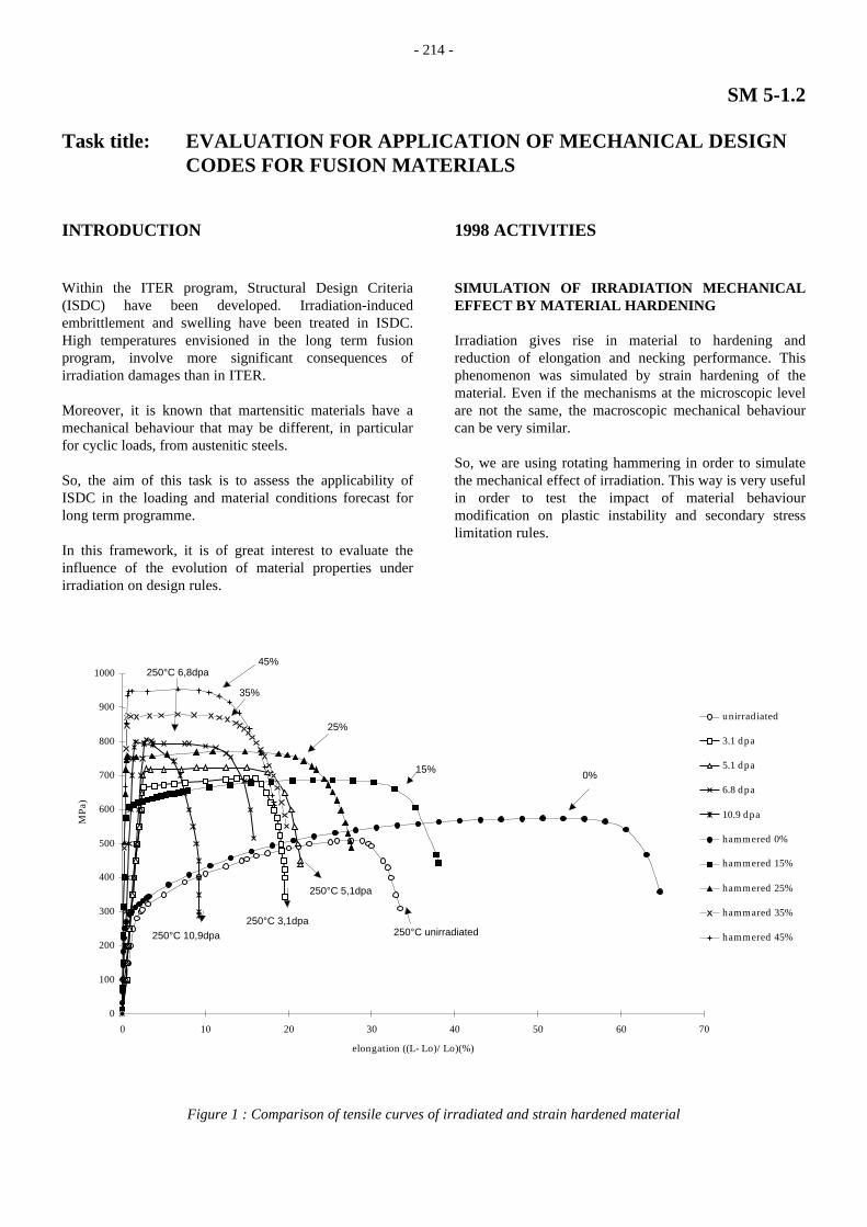
Irradiation gives rise in material to hardening andreduction of elongation and necking performance. Thisphenomenon was simulated by strain hardening of thematerial. Even if the mechanisms at the microscopic levelare not the same, the macroscopic mechanical behaviourcan be very similar.
So, we are using rotating hammering in order to simulatethe mechanical effect of irradiation. This way is very usefulin order to test the impact of material behaviourmodification on plastic instability and secondary stresslimitation rules.
0
100
200
300
400
500
600
700
800
900
1000
0 10 20 30 40 50 60 70
elongation ((L- Lo)/Lo)(%)
MPa
)
unirradiated
3.1 dpa
5.1 dpa
6.8 dpa
10.9 dpa
hammered 0%
hammered 15%
hammered 25%
hammared 35%
hammered 45%
0%15%
25%
35%
250°C unirradiated250°C 3,1dpa
250°C 5,1dpa
250°C 6,8dpa
250°C 10,9dpa
45%
Figure 1 : Comparison of tensile curves of irradiated and strain hardened material
- 215 -
Starting from the rapid quenched state, we performed 4controlled deformation levels (15%, 25%, 35%, 45%).Thereafter, tensile tests have been carried out on bothsmooth and notched tensile bars. The mechanical resultsalready obtained (figure 1) are very encouraging and giveus all the experimental base for the definition andvalidation of design rules. We have also performed anexperimental program with four point bending tests onsmooth and notch specimens in order to validate also thecriteria in bending.
The report SEMT/LISN/RT/98-038/a, intitled« development of new design rules for low ductilityaustenitic » gives the details of these results and has beensent to the designated persons.
INSTABILITY CONDITIONS OF THE MATERIALON NOTCHED SPECIMENS
The experimental tests on notched specimen have shownthat the conditions of instability and rupture in notchedtensile specimens are largely influenced by the structuraleffect occurring in this geometry. Simple methods arepresented here in order to use the values obtained from atensile test on a smooth tensile specimen and then tocalculate the values for the notched specimen. Differentinvestigators like Bridgman have shown that instabilityconditions can be correlated with triaxiality factor. Thisfactor is here defined as the hydrostatic pressure divided bythe equivalent (Von Mises) stress.
This value is calculated at the centre of the reduced sectionwhere it is maximal. For notched tensile specimens, it hasbeen demonstrated that the initial triaxiality factor TF isgiven by:
++=
R2
a1Ln31TF (1)
where a is the radius of the minimal section and R theradius of the notch and TF value is normalised to give theunity in the pure uniaxial stress state.
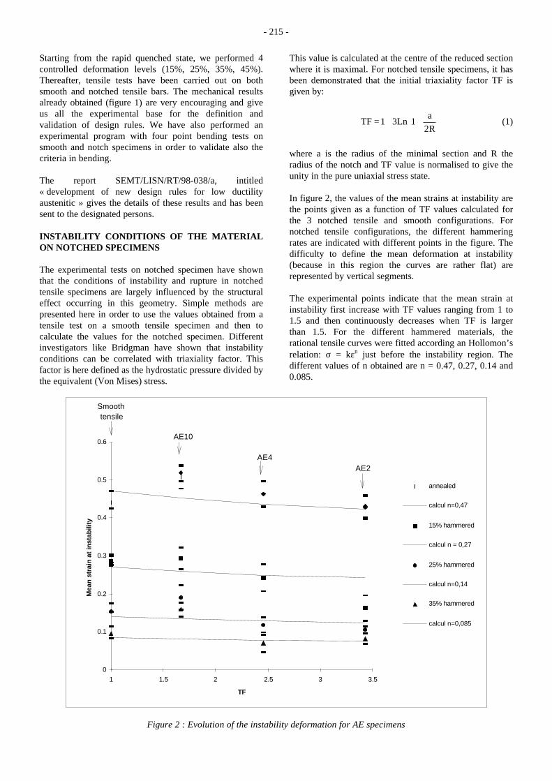
In figure 2, the values of the mean strains at instability arethe points given as a function of TF values calculated forthe 3 notched tensile and smooth configurations. Fornotched tensile configurations, the different hammeringrates are indicated with different points in the figure. Thedifficulty to define the mean deformation at instability(because in this region the curves are rather flat) arerepresented by vertical segments.
The experimental points indicate that the mean strain atinstability first increase with TF values ranging from 1 to1.5 and then continuously decreases when TF is largerthan 1.5. For the different hammered materials, therational tensile curves were fitted according an Hollomon’srelation: σ = kεn just before the instability region. Thedifferent values of n obtained are n = 0.47, 0.27, 0.14 and0.085.
0
0.1
0.2
0.3
0.4
0.5
0.6
1 1.5 2 2.5 3 3.5
TF
Mea
n s
trai
n a
t in
stab
ility
annealed
calcul n=0,47
15% hammered
calcul n = 0,27
25% hammered
calcul n=0,14
35% hammered
calcul n=0,085
Smooth tensile
AE10
AE4AE2
Figure 2 : Evolution of the instability deformation for AE specimens

- 216 -
According to this equation and using the formulaedeveloped by Bridgman and assuming that the R radiusdoes not change during the loading, the following equationwas obtained to calculate the strain at instability :
n
11
12
1Ln2
21Ln
212
ins
+
α+
α
+
α
+
α+
=ε with initialR
a
=α (2)
If α tends toward zero, the above equation is reduced to thewell known Considere equation :
n=ε (3)
The values calculated with equation (2) are represented bythe lines drawn on figure 2. The experimental pointsfollows the same general trends of reduction against TFand hammering rates as predicted by this equation.
FAILURE CRITERION ON NOTCHED SPECIMENS
In figure 3, the failure points in term of mean strain of thetests on notched tensile specimens are plotted versustriaxiality factor.
The triaxiality factor is calculated according to theBridgman formulation with initial geometry. The results ofmean strains at rupture are normalised to the mean strainobtained at rupture for the tensile test on smooth specimen.
For ductile materials, Mc Clintock has developed a damageapproach (based on void growth) which shown that strainat rupture can be estimated by the equation :
( )TF.Asinh
Brup =ε (4)
where A and B are 2 constants depending only of thematerial. For positive triaxiality factor this equationbecomes :
( )TF.AexpB
rup =ε (5)
By normalisation with the strain at rupture of tensile testsεrup
tensile the equation is reduced to :
( )[ ]TF1Aexptensileruprup −ε=ε (6)
0
0.2
0.4
0.6
0.8
1
1.2
1 1.5 2 2.5 3 3.5 4TF
ε /
ε (T
F=
1)
316L annealed
A=0,11
316L 15% hammered
A=0,341
316L 25% hammered
A=0,455
316L 35% hammered
A=0,57
A=0.86
Figure 3 : Normalised mean strain at rupture versus triaxiality ratio

- 217 -
Mac Clintock has shown that A parameter is proportionalto strain hardening coefficient n. This has been found alsoin our experimental results. The A values are calculatedfrom εrup and TF experimental values with the upperequation. This gives a linear correlation with the n valuesthat were obtained by fitting of n parameter of anHollomon’s equation of the tensile curves on smoothspecimen.
This model gives a fairly good approximation of theexperimental results obtained. For comparison, Figuregives also the reduction calculated by Mac Clintock for aplastic perfect material (n=0) for which A=0.86 isproposed.
CONCLUSIONS
The four tasks which were scheduled in this program arenow achieved. The first task was entitled "Needs formaterials characteristics - Compilation of availablematerials characteristics". The second one was entitled"Local approach use assessment". The third one iscorresponding to "Experimental validation tests". Finally,the last item was "Evolution of ISDC to a general fusionreactors design guidance"
This set of work can now be use for the definition of aneventual evolution of ISDC rules. Further work will berequired for the low cycle fatigue regime or the elastic-plastic fracture mechanics area.
REPORTS AND PUBLICATIONS
[1] GOUIN H., SAINTE-CATHERINE C. and MOULIND., "Development of new design rules for LowDuctility Steels", CEA Saclay, France, ReportSEMT/LISN/RT/98-038, (1998).
[2] BRACHET J-C., "Properties and Data of EM 10Steel - Comparison with some Commercial andExperimental Alloys, including Low Activation9 Cr(N,V,Ta) Steels", CEA Saclay, France, ReportCEREM-SRMA-96/200, (1996).
[3] SAINTE CATHERINE C. and MARINI B., "Localapproach assessment", CEA Saclay, France, ReportDMT-95/667, (1995).
[4] TOUBOUL F., "Programme Long Term Fusion:evaluation of the needs for materials characteristics",CEA Saclay, France, Report DMT-95/440, (1995).
TASK LEADER
Claude SAINTE CATHERINE
DRN/DMT/SEMT/LISNCEA Saclay91191 Gif-sur-Yvette Cedex
Tél. : 33 1 69 08 88 56Fax : 33 1 69 08 87 84
E-mail : [email protected]

- 218 -
SM 6-4.2Task Title : MICROSTRUCTURAL CHARACTERISATION BY SANS
TECHNIQUESMicrostructural characterisation after thermal ageing of LAM and conventionalmartensitic steels by Small Angle Neutron Scattering
INTRODUCTION
Low Activation Martensitic (LAM) steels are candidatesfor internal structures of fusion reactors. The concept ofLow Activation steels or Reduced Activation steels wasintroduced for new materials that offer benefits onmaintenance operations and waste management. Formartensitic/ferritic steels, the main alloying elements suchas molybdenum, niobium and nickel present in commercialsteels are substituted by elements such as tungsten,vanadium, manganese and tantalum. These elements havea similar influence on the constitution and structure butexhibit a lower radiological impact.
In order to assess low activation materials and tounderstand the effect of the substitution of W to Mo and Tato Nb on the evolution of the microstructure during long-term ageing, LAM alloys and also conventional steels arecharacterised by Small Angle Neutron Scattering (SANS).
1998 ACTIVITIES
LAM alloys F82H, JLF1, LA12LC and LA12TaLC werecharacterised by Small Angle Neutron Scattering (SANS)before and after ageing [1] and the results were comparedto those acquired previously on conventional steels (EM10and HT9)[2].
MATERIALS
The chemical compositions of the steels used in this studyare listed in table 1. The Japanese steels F82H and JLF-1alloys contain respectively (%wt) 7.5Cr -2W and 9Cr-2Wand are large industrial heats. Compared to F82H and JLF-1, the LA12LC and LA12TaLC alloys (9Cr-0.8W), containlow concentrations of W. These two last materials allow tostudy the effect of a low W and Ta content on themicrostructure evolution under thermal ageing.
The alloys were austenitized at high temperature, then theywere tempered at 750/780°C during 1 hour. Some of thestudied materials have been 10% cold rolled. The details ofthese treatments for each material are given in table 2.After these thermal treatments, a fully martensitic structureis obtained for all the alloys except for HT9 which presentsa small amount of delta-ferrite (<3%) in the martensiticstructure.
After normalisation and tempering treatments, thepredominant precipitated phase is a chromium rich M23C6
carbide. These particles are located preferentially alongprior austenite grain boundaries and along lath boundaries.The chemical composition of the M23C6 was measured byTEM on carbon extraction replica and does not reallydiffer from LAM and conventional alloys. It is about35%Fe-60%Cr-5%W/Mo (in atomic %) [3,4] and for theF82H steel no other precipitation has been detected [5].Other second phases M2X and/or MC are also detectedrespectively in EM10 and HT9. Some particles of Ta(N,C)and of MX (M=11%Cr, 77%V, 10%Fe) have beenobserved in the JLF-1 alloy [5]. For the LA12LC andLA12TaLC, the TEM observations have not yet beenperformed, but we could expect that V-rich MX andTa(N,C) (only in the Ta rich alloy) precipitates are present.
The normalised and tempered specimens, HT9 and EM10,were aged at 400°C, 450°C and 500°C up to respectively22000 h and 15000 h. The LAM alloys were aged at250°C, 350°C, 400°C, 450°C and 550°C up to 13500 h forF82H and JLF-1, and up to 5000 h for LA12TaLC andLA12LC.
Table 1 : Chemical analysis of experimental steels (wt %)
Steel Cr W Mo Ni Mn Ta V Si C N
F82H 7.46 1.96 0.21 0.023 0.15 0.10 0.087 0.006
JLF-1 8.7 1.91 0.47 0.08 0.18 0.05 0.10 0.028
LA12TaLC 8.9 0.76 1.01 0.1 0.39 0.03 0.09 0.019
LA12LC 9.0 0.76 1.01 0.38 0.03 0.09 0.033
EM10 8.8 1.0 0.2 0.02 0.1 0.024
HT9 12 0.5 1.0 0.6 0.3 0.1 NA*
* Not Analysed
RESULTS
Measurements have been made at room temperature, undersaturating magnetic field H=2T perpendicular to theincident neutron beam direction in order to separatemagnetic and nuclear scattering.
LAM alloys
F82H alloy
The intensities obtained on F82H samples present ananisotropy, before and after ageing, even in absence ofmagnetic field. This anisotropy is probably the result of amorphologic texture of the microstructure i.e. apreferential orientation of the precipitates in the matrix.

- 219 -
The scattered intensities obtained as a function of thescattered vector q and measured on the samples aged13500 h are presented in figure 1. There is no evolution ofthe microstructure in comparison with the referencesample (without thermal ageing). All the SANS intensitiesare identical taking into account the error bars. Thescattered intensities are high at low q and correspond tolarge size precipitates, i.e. the M23C6 carbides initiallypresent in the material.
0.01
0.1
1
10
100
0 0.05 0.1 0.15 0.2
F82H referenceF82H aged 13500h at 350°C F82H aged 13500h at 400°C F82H aged 13500h at 550°C
scat
tere
d in
tens
ity
q ( A -1 )
Figure 1 : Scattered intensities measured, without appliedmagnetic field, on F82H samples before (reference)
and after thermal ageing for during 13500 h at differenttemperatures
At low q, the A ratio(ratio on the scattered intensitiesmeasured perpendicularly and parallel to H) of M23C6
carbides is about 4-4.5. The A ratio calculated using thechemical composition measured by TEM, i.e. 35%Fe65%Cr 5%W, is 3.5. This value depends on manyparameters which are unknown precisely, such as theatomic volumes in the matrix and in the precipitate, andthe magnetic moments. So, to estimate the A ratiocorresponding to the carbides, we used theoretical values(the atomic volume has been deduced from tabulatedCr23C6 cell parameters, the magnetic moment is takenequal to that of pure iron). Taking into account of thisuncertainty, the measured A ratio at low q is in agreementwith chemical composition of the carbides determined byTEM.
JLF-1 alloy
The JLF-1 alloy has been characterised by SANS after :2000 h at 550°C and 13500 h at 250°C, 400°C and 500°C.The variation of scattered intensity in comparison with thereference sample is too weak to be considered asrepresentative of a microstructure evolution. At 550°C, theSANS intensity seems to increase at low q with ageing.Some SANS measurements have been made with andwithout magnetic field and have confirmed this behaviourbut this evolution of SANS intensity with the ageing at550°C is too weak to be interpreted.
Furthermore, the A ratio measured at low q, does notchange with ageing and is about 3-3.5. This value isslightly lower than for F82H alloy, although the chemicalcomposition of the M23C6 carbides is not significantlydifferent in these two materials. The difference of the Aratio between the steels is significant and probablyrepresentative of the presence of additional or differentphases. Quantitatively, it is very complicated to calculate amean A ratio resulting of several kinds of particles becauseeach contribution has to be weighted by its correspondingform factor and by the number density of each phase. TheA ratio in a pure iron matrix is for TaC equal to 10, for VNit is equal to 3.9 and for VC it is equal to 2.23.Qualitatively, only the VC or VN or V[N+C] particles caninduce a decrease of the mean A ratio. Indeed, the presenceof TaC carbides should sharply increase the A factor. So,to explain the results obtained on JLF-1, we have toassume that the contribution of the V(N,C) particles in thematrix have an important effect on the mean observed Aratio.
LA12TaLC and LA12LC alloys
As for JLF-1 and F82H materials, we did not observe bySANS any significant variation of the scattered intensityafter ageing ( figure 2). The A ratio measured at low q isabout 2.5 for the LA12LC alloy and 3 for the LA12TaLCalloy.These values are lower compared to the other alloys.The A ratio is higher for the Ta rich alloy which iscompatible with the presence of Ta(N,C) in the matrix ofLA12TaLC and not in the matrix of LA12LC.
0.01
0.1
1
10
100
0.02 0.04 0.06 0.08 0.1 0.12 0.14 0.16
LA12LC reference
LA12LC aged 5000h at 250 °C
LA12LC aged 5000h at 400 °C
LA12LC aged 5000h at 450 °C
LA12LC aged 5000h at 550 °C
scat
tere
d in
tens
ity
⊥ H
q ( A -1 )
Figure 2 : Intensities scattered perpendicularly tomagnetic field measured on LA12LC samples before
(reference) and after thermal ageing for during 5000 h atdifferent temperatures
Conventional alloys
For these alloys (in contrast with the LAM materials), aftereach ageing treatment, we observed an increase of thescattered intensity in comparison with the referencesample.

- 220 -
So, the intensities presented are obtained after subtractionof the reference sample (without thermal ageing). Thescattered intensities obtained on HT9 alloy thermally aged22000 h at 400, 450 and 500°C are plotted in figure 3.
0.001
0.01
0.1
1
10
100
0 0.5 1 1.5 2
400°C450°C500°C
Inte
nsity
q ( nm-1
)
Figure 3 : Intensities scattered perpendicularly tomagnetic field, obtained after subtraction of the referencesample, measured on HT9 samples thermally aged 22000 h
at different temperatures
EM10 alloy
The scattered intensities after treatment at 400 and 450°Care similar and markedly lower compared to thoseobserved after ageing at 500°C.
For thermal ageing at 400°C and 450°C, mechanicalproperties show a clear hardening with the same intensityfor the two ageing temperatures [6]. The scatteredintensities could correspond to the microstructuralevolution responsible of this hardening. The data treatmentshows that the SANS profiles can be interpreted with adistribution of particles with a mean radius close to 3 nm.The A ratios are constant on the whole measured q domainand equal to 3.5 ± 0.6. This value could correspond toseveral kinds of particles : M2C carbides with the followingchemical content M(at%)= 83Cr, 12Fe, 5Mo, or VCcarbides. The precipitation of M2C is not expected becauseduring thermal ageing at those temperatures they seem todisappear [7]. Moreover, preliminary thermodynamiccalculations showed that, at the equilibrium, these carbidesare present only between 600 and 850°C.
At 500°C, the intensity is higher and follows a PORODlaw (I ∝ A/q4) characteristic of large size particles. Thiskind of profile can be due to Laves phases at grainboundaries. The A ratio is equal to 6 ± 1, which isconsistent with Fe and Mo rich particles such as the Lavesphase Fe2Mo observed by TEM.
HT9 alloy
The behaviours at 400 and 450°C are different, theintensity at 400°C is lower than at 450°C and 500°C.
On the other hand, we note only a small evolution between450°C and 500°C as it is shown on figure 12. At hightemperature, the scattered intensities follow a POROD law(I ∝ A/q4) as for the EM10 alloy. Furthermore, the A ratiois equal to 3.45 ± 0.5 and 4 ± 1 respectively for 450°C and500°C, which is consistent with Fe2(Mo,W) Laves phase.Indeed, the substitution of Mo by W in the Laves phaseinduces an important decrease of the calculated A ratio(compared to the case of EM10, aged at 500°C, containingno W).
At 400°C, the study of the form factor shows that theradius of the particles is around 1nm. The associated Aratio is equal to 2 ± 0.4, in agreement with the valueexpected for alpha-prime clusters. With the assumption ofalpha prime-clusters containing 90%Cr and 10%Fe, theprecipitated volume fraction is around 0.25%. For thisthermal treatment, no new phase has been observed byTEM.
CONCLUSIONSSANS experiments were performed on Low ActivatedMaterials JLF-1, F82H, LA12TaLC and LA12LC and onconventional alloys EM10 and HT9. These measurementshave been made several times in order to confirm theresults and to define the experimental error bars.
This study confirms the different behaviours under thermalageing between the conventional and LAM alloys.
In the conventional alloys HT9 (12Cr 1Mo-W) and EM10(9Cr 1Mo), the SANS results have shown, in agreementwith TEM observations, the formation of Laves phaseunder thermal ageing beyond respectively 450°C and500°C with a chemical composition depending on the Wand Mo initial content. A higher precipitated fractionprobably occurs in HT9 due to the higher Mo+Wconcentration. The fact that no Laves phase occurs at450°C in the EM10 can be explained by the lowprecipitation kinetics at this temperature. At lowertemperature (400°C), in the conventional alloys, weobserved the formation of alpha- prime clusters in HT9 andof a new precipitation in EM10 which are probably at theorigin of the hardening observed on mechanical properties.
In LAM steels, the structure developed after temperingseems to be stable under thermal ageing up to 13500h attemperature between 250°C and 550°C. The measuredscattered intensities correspond essentially to the M23C6
carbides present after tempering treatment. The A ratioshows some variations with chemical composition of thealloys which can be due to the presence before ageing ofother kinds of precipitates (VX or TaX). Under thermalageing, no significant evolution has been detected in F82H,JLF-1, LA12TaLC and LA12LC alloys whatever theageing temperature. In particular, no Laves phase wasdetected at 550°C even in the high W content steels (F82H,JLF-1).

- 221 -
Due to the very low solubility of W and Mo in iron, wecould expect the formation of the intermetallic Fe2(W,Mo)in all the alloys. It seems that the precipitation kinetic ofthe Laves phase in W rich steels is hindered by the weakdiffusion of the W in iron.
Furthermore, at low temperature, no new phase wasdetected in studied LAM alloys although that the Crcontent is quite similar in EM10 and JLF-1, LA12LC andLA12TaLC.
Finally, the LA12TaLC and LA12LC exhibit similarmicrostructure stability under ageing, so no significanteffect of tantalum on precipitation evolution has beenobserved excepted a slight increase of the A Ratio.
In order to clarify the role of each main element, studies ofmodel LAM alloys (LA4Ta, LA12Ta and LA13Ta)thermally aged between 250 and 550°C are in progress.
REPORT
[1] M.H. MATHON, G. GEOFFROY, C.H. de NOVION,Y. DE CARLAN, A. ALAMOMicrostructural caracterisation after thermal ageingof LAM and conventional martensitic Steels by SmallAngle Neutron Scattering - Final Report contract SM6.4.2 - Note Technique : LLB/98/108 - LSI/98/03
REFERENCES
[2] M.H MATHON, G GEOFFROY, C.H. de NOVION,Y. DE CARLAN, A ALAMO,Microstructural characterisation of EM10, HT9,F82H and JLF1 steels by small angle neutronscattering, Note technique LLB/97/170-LSI/98/01.
[3] A. ALAMO, C. LEPOITTEVIN, F. NEE, C.BOUSSIDAN, Effects of heat treatments and phasetransformations of F82H and JLF-1 low activationmartensitic steels, Progress Report NT SRMA 96-2211, dec. 1996
[4] C. BOUSSIDANDétermination des fractions de phases à l’équilibrethermodynamique de différents aciers inoxydablesd’interêt nucléaire. - C.R. SRMA 95-1519, août 1995
[5] Y. de CARLAN , A. ALAMO, Effect of thermalageing on microstructure and mechanical propertiesof 7.5/9 Cr (W/Ta/V) Reduced Activation martensiticsteels - final Report - Contract UT-SM&C 2.1.1 - NTSRMA to be published
[6] J.L. SERAN, A. ALAMO, A. MAILLARD, H.TOURON, J.C. BRACHET, P. DUBUISSON, O.RABOUILLE - J. Nucl. Mater. Vol. 212-215 (1994),p 588
[7] J.C. Brachet, CEA report, CEA R-5581, France, 1991
TASK LEADER
A. ALAMO
CEA Saclay91191 Gif-sur-Yvette Cedex
Tél. : 33 1 69 08 67 26Fax : 33 1 69 08 71 30
E-mail : [email protected]

- 222 -
WP5Task Title : COORDINATION
Materials R&D Strategy for Future Fusion Reactors
INTRODUCTION
Until recently, the fusion technology programme had anear term goal and a long term goal. The near term goalaimed at construction of an International ThermonuclearExperimental Reactor (ITER) in about 10 years time andwas carried out jointly by four Home Teams (EU, JA, RF,US). The long term goal focussed on post ITER machinesand was carried out primarily at the national level, thoughthe R&D programmes were usually harmonised underdifferent IEA implementing agreements. The transitionbetween the two goals was insured through testing ofBreeding Blanket Module concepts in ITER.
With the recent changes in the fusion technologyprogrammes, at the national and international levels, thenear term objectives are scaled down and the long termobjectives delayed. This paper addresses the consequencesof such changes on the EU materials long termprogrammes and attempts to develop a materials strategyfor the future work. It is based on a presentation made atan IEA Sponsored Workshop on “Strategic Planning andCo-ordination of Research on Fusion Structural Materials”,5-7/9/98 RISÖ National Laboratory, Denmark.
1998 ACTIVITIES
MATERIALS R&D STRATEGY
The most likely scenario for the next step machine is areduced cost machine and/or an extension of existingfusion machines. ITER Test Blanket Module programmehas to be adapted to the new machine. The delay in thelong term program could be used for evaluation ofalternative reactor concepts. Though the present liquidand solid breeding blanket concepts should remainamongst the primary solutions, the possibility of a differentapproach can not be ruled out. As a result, the materialsprogramme must incorporate a certain degree of flexibilityand design independence.
To develop such a long term materials strategy, one couldmake a number of assumptions that would apply to anyfuture fusion reactor concept and based on thoseassumptions derive the target materials requirements.
Assumption 1 : The future reactor would operatein a continuous mode
In a continuous operation mode, the reactor is onlyperiodically shut down for maintenance. For instance, in apool type fission reactor, each operation cycle time is aboutone month, in a research type reactor such as Phénix it isabout three months, and in a commercial reactor it is overone year. As a result, we can reasonably deduce that thenumber of thermal fatigue cycles resulting from normalstart-ups and shut-downs would be small, about 20 to 200times. In another word, the number of thermal fatiguecycles (excluding plasma disruptions) will be small, but theexposure time and the neutron doses much higher.
Conclusion: Target materials may not need to exhibit ahigh resistance to thermal fatigue resistance, but have towithstand exposures to high neutron irradiation doses (100to 200 dpa).
Assumption 2 : The future reactor has to be economical
A number of factors determine the economy of a reactor.From the thermal efficiency point of view, the reactor mustoperate at higher temperatures. A higher servicetemperature would:
1) accentuate the creep damage,2) modify the choice of coolant,3) change the irradiation damage mechanism.
At low irradiation temperatures, the main damagemechanism is hardening associated with a reduction inductility and toughness. At high irradiation temperatures,radiation hardening is less pronounced but swelling andgrain boundary embrittlement are enhanced. The lattertwo mechanisms are intensified with the increasingirradiation dose.
Since some components or part of the same componentmay operate at lower temperatures, the target materialsmust also resist low temperature irradiation embrittlement.
Conclusion: The target materials must have good elevatedtemperature mechanical properties, be compatible with thecooling medium and resist low and high temperatureirradiation damage.
Assumption 3 : Low activation materials
This assumption applies to materials that yield lower shortterm (for intervention) and lower long term (for storage)activation characteristics.

- 223 -
Two solutions can be envisaged. One is to develop lowactivation grade materials from the existing conventionalalloys (more affordable solution), the other is to developtotally new alloys from advanced or alternative materials(requires more extensive R&D work).
A reduction of high activation trace elements or impuritiesin commercial materials is a generic problem and is tied totechnological advances and cost. It is, therefore, thepresence of major alloying elements that determine theirthe aptitude of a materials towards low activation gradedevelopment.
In a typical stainless steel alloy composition, nickel,molybdenum, and niobium are the principal causes ofactivation. Molybdenum and niobium can be easilyreplaced with their equivalent low activation elements. Incontrast, replacing nickel with another element meansdeveloping a totally new alloy.
The situation of ferritic / martensitic steels is different.Here, nickel is not a principal alloying element and Moand Nb are present in small amounts and can be replacedwith other elements (e.g. W, V, Ta).
In the category of advanced / alternative materials,vanadium alloys and silicon carbide ceramics offer anexcellent combination of low activation and hightemperature resistances.
Conclusion: Ferritic / martensitic steels offer the easiestand most reliable transition from the current qualifiedfamily of materials to the low activation materials. Thefuture R&D work needed for these alloys is mainly refiningof specifications developed under current nationalprogrammes and generation of design data for differentproduct sizes and forms. Development of high temperaturegrades (e.g. ODS) should also be part of this work.Alternative materials, such as vanadium alloys andceramic carbides offer higher service temperaturepotentials. The scope of the R&D work for these materialsshould remain open and responsive in the next few years tothe results of the ongoing work and technologicaladvances.
Assumption 4 : A variety of materials will be needed
The operating conditions of various components in a fusionreactor vary significantly. Often one has to use differentmaterials or a combination of materials to satisfy theseconditions. For instance, in ITER, Be was envisaged as anarmour material in the primary modules, but W and CFCwere chosen for the lower modules and divertor region.Copper and copper alloys were placed on the stainless steelto act as a heat sink. Nickel and titanium alloys wereenvisaged for attachment of primary modules to the back-plate.
Conclusion: A large number of materials have to beinvestigated. However, most of these can only be identifiedat a later stage of design or after qualification in the nearterm machines.
Assumption 5 : Advanced Fabrication Methods
The complex geometries of first wall, blanket and vacuumvessel require advanced fabrication methods. These includesolid and powder HIPing, casting, diffusion bonding,brazing, etc.
Conclusion: Target materials must be compatible with theadvanced fabrication techniques.
Assumption 6 : Joining, inspection and repair techniques
It is imperative to develop appropriate joining, inspectionand repair techniques for materials used in fusion reactors.In fact, the choice of a material can be governed by theavailability of such techniques for that material.
Conclusion: Identify and develop appropriate joining,inspection and repair techniques for target materials.
GENERAL SUMMARY AND CONCLUSIONS
A number of assumptions are made in this paper regardingthe needs of future fusion reactors. From theseassumptions, principal requirements of structural materialsand related R&D programmes are derived. These can beclassified under three themes.
1) Principal axis of R&D Ferritic/martensitic steels are confirmed as the
reference target materials for future fusion reactors.Work to be done on these materials in the next fewyears includes fine tuning of compositions andproduction of design data. Higher temperature gradesof F/M steels, e.g. ODS, should be developed forspecific applications.
2) Alternative materials Alternative materials such as vanadium alloys and
ceramic carbides offer a greater potential for futurereactors. The scope of the R&D programme for thesematerials should, nevertheless, remain open andresponsive to the ongoing work and the technologicaladvances.
3) Mechanistic studies Since the damage mechanisms resulting under true
fusion environments (e.g. 14 MeV neutrons) are notfully understood, the R&D programme should integratebasic studies and experimental facilities for validatingand guiding future programmes.
- 224 -
ACKNOWLEDGEMENTS
The strategy developed in this paper is based on the resultsobtained in various EU laboratories and contributions fromassociations at national and international levels, inparticular the IEA Implementing Agreement for aProgramme of Research and Development on FusionMaterials.
REPORTS AND PUBLICATIONS
[1] F. Tavassoli , Target Materials PerformanceCharacteristics And Critical Issues As EstablishedFor Fusion Power System, IEA Sponsored Workshopon “Strategic Planning and Co-ordination of Researchon Fusion Structural Materials”, 5-7/9/98 RISONational Laboratory, Denmark
TASK LEADER
Farhad TAVASSOLI
DTA/CEREM/DECMCEA Saclay91191 Gif-sur-Yvette Cedex
Tél. : 33 1 69 08 60 21Fax : 33 1 69 08 71 31
E-mail : [email protected] or [email protected]

- 225 -
WP3-3.3Task Title : CHARACTERISATION OF MATERIAL, SPECIFIC TESTS AND
PERFORMANCE CONSIDERATIONS OF LOW ACTIVATIONCERAMIC COMPOUNDS (LACC) SUCH AS SiCf/SiC
INTRODUCTION
The use of SiCf/SiC composites as structural materialappears essential to demonstrate the potential of D-TFusion Power Reactors (FPR) in terms of safety. The lowactivation- and afterheat-level associated with SiCf/SiCafter long-term neutron irradiation permits to design FPRnuclear components showing high safety standards andsimplified maintenance schemes.
In particular two strategies [1] can be conceived : i)minimize the inventory of activation in the plasmachamber such as inherent safety can be achieved, whichleads to the ARIES-type proposals for breeding blanketusing Helium as coolant and Lithium-based ceramics astritium breeder, and ii) minimize the energy inventory inthe plasma chamber leading to passive safety, as obtainedin the TAURO-type proposal using Pb17Li as coolant andbreeder. In the first case accidental releases haveminimized radiological consequences for the public, in thesecond case accidental releases have minimized occurrenceprobability.
Within this framework, in the last couple of years theactivities of CEA, which started in 1992, have beenconcentrated on the development of the TAURO conceptand on the definition of the main issues related with theuse of SiCf/SiC composite as FPR breeding blanketstructural material when comparing the required materialproperties with present-day characteristics of industrialSiCf/SiC.
Experimental activities for developing joining techniquesfor SiCf/SiC (e.g., brazing) are also being performed atCEA. In fact, these activities have continued in 1998without support from the EU technology program and,therefore, will not be reported here.
1998 ACTIVITIES
With reference to the 1997 Progress Report [2], theactivities in 1998 have further been focused on theassessment of the use of SiCf/SiC as structural material forfusion in-vessel components application and on thedevelopment of the TAURO blanket design.
ASSESSMENT OF THE USE OF SiCf/SiC AS IN-VESSEL COMPONENTS STRUCTURALMATERIALS [1]
The comparison of the characteristics of present-dayindustrial materials with those required when ceramiccomposites are used as structures of in-vessel componentsin FPR can give an idea of the R&D efforts and lead timefor obtaining a satisfactory fusion-relevant SiCf/SiC. Thisassessment, which was the most important objective of the1995-98 activities, is shortly summarized hereafter.
Main characteristics of present-day industrial SiCf/SiC
Recently developed by SEP, a 3-dimensional SiCf/SiC
composite, the Cerasep N3-1, has been industriallymanufactured in 1996. Its main characteristic are given inTable 1 in comparison with those used in the design
analyses. Cerasep N3-1 is based on an advanced texture,
called GUIPEX, a multilayer 3D texture in which a thirdtexture direction, created by linking the layers duringweaving, avoids delamination risks when shaping anddensifying the parts.
Furthermore, GUIPEX texture permits the manufacture
of parts with very complex shape. Cerasep N3-1 has thesame raw components as the previous 2D version, that isNL207 Nicalon fibers and SiC matrix (CVI process).Therefore, most results of tests obtained for 2D-materials,such as compatibility tests, can be extended to this new3D-material.
In order to improve the composite irradiation resistance,
the Cerasep N4-1 is under development ; this new
material has the same structure of the Cerasep N3-1 butit uses Hi-Nicalon fibers which leads to a reduced Oxygen-content in SiCf/SiC of 0.2 wt% instead of 4.6 wt%. It isexpected that the maximum operating temperature of thisnew composites can be significantly increased up to1400°C.
At present, the maximum thickness that can bemanufactured is 6 mm, lower than the 10 mm FW-thickness assumed for TAURO. Techniques for achievingthe fabrication of higher wall thickness need therefore tobe developed.

- 226 -
Table 1 : Main characteristics (and uncertainties) of present-day industrial SiCf/SiCcomposite compared with those used in the calculations
SiCf/SiC CharacteristicsTemperature
(°C)Assumed in TAURO
analysesMeasured for Cerasep
N3-1
Density 20 2.5 g/cm3 > 2.4 g/cm3
Porosity 20 10 % (10 ± 2) %
Fiber content - 40 % 40 %
Tensile strength (in plane) 20 285 MPa (300 ± 20) MPa
Tensile strain (in plane) 20 0.65 % (0.80 ± 0.25) %
Young Modulus (in plane) 20 230 GPa (200 ± 20) GPa
Trans-laminar shear stress (x-y) 20 - (200 ± 20) GPa
Inter-laminar shear stress (x-z) 20 40 44 MPa
Thermal Conductivity (in plane) 1000 15 W/m/K 15 W/m/K
Thermal conductivity (along the thickness, z) 208001000
15 W/m/K15 W/m/K15 W/m/K
(13 ± 2) W/m/K7.6 W/m/K7.5 W/m/K
Thermal expansion coeff. (in plane) 20 3.0 x 10⁻⁶ K-1 4.0 x 10⁻⁶ K-1
Fracture toughness 20 30 MPa m-1/2 -
Poisson ratio, n 20 0.18 -
Assumed joining techniques (i.e., assembling duringmanufacturing at a textile or intermediate densificationstage and/or brazing between finished components)require, in order to be efficient in a fusion environment, tobe further developed and tested [3].
It is known that the presence of some kind of impuritiescan considerably jeopardize the advantages of using low-activation materials. In the case of SiCf/SiC, informationfrom industry are available on SiC, but very little is knowfor the composite. However, because of the fabricationmethod using CVI used for the SiCf/SiC, the onlysignificant impurities are those present in the SiC-fiber.Table 2 summarizes the maximum levels of impurities thathave been measured for Nicalon-NL207 fibers and,therefore, that can be expected in present-day industrialSiCf/SiC.
Effects of neutron irradiation
Neutron irradiation have several deleterious effects on thecomposites characteristics. The major ones, mainly due toatoms displacements (dpa) and He-production, are thereduction of thermal conductivity, the expected increase ofelectrical conductivity, the reduced stability of the fibers tobulk SiC-interface, the swelling, the fiber densification,and the irradiation creep. Performed neutron irradiationexperiments on SiCf/SiC are in the dpa-level range of 20to 50, to be compared at the more than 100 dpa expected inFW of in-vessel components. Promising behavior onradiation stability has been shown from Hi-Nicalon fiberswith a reduced Oxygen content.
Table 2 : Chemical composition of industrialSiCf/SiC using Nicalon NL207 fibers
Element wt% Element wt% Element wt%
Si ~ 66.8 C ~ 30.1 O ~ 4.1
N 0.114 Al 6.3E-5 Cl 0.03
Ti 1.9E-4 V 3.0E-5 Cr 8.0E-4
Mn 2.9E-5 Fe 7.7E-3 Co 4.4E-5
Ni 4.2E-4 Cu 3.0E-4 Zn 8.3E-5
As 1.0E-5 Zr 1.0E-4 Nb 5.0E-4
Mo 4.0E-4 Ag 1.0E-5 Sn 3.0E-4
Sb 5.3E-6 Nd 1.0E-4 Eu 6.6E-8
Tb 2.0E-7 Hf 1.2E-6 Ta 1.1E-5
W 4.9E-5 Os 3.0E-3 Pb 1.0E-4
Na 3.2E-4 K 8.0E-4 Sc 7.6E-4
Br 4.7E-6 La 2.2E-6 Ce 1.1E-6
Au 6.0E-6 Hg 6.0E-7 Ga 4.8E-6
Thermal conductivity
Out-of-pile values of thermal conductivity for industrially-available SiCf/SiC are already too low for their use inplasma-facing components (e.g., blanket FW, divertor,etc.); neutron irradiation will reduce even further suchvalues; a significant improvement of the thermalconductivity of present-day SiCf/SiC (a factor 3 or more)has to be obtained; this could probably be done by addingsome doping materials and/or by using advanced SiCfibers; the choice is more limited for He-cooledcomponents.

- 227 -
T-inventory and chemical stability
Very few information is available on the T-retention ofSiCf/SiC. Kinetics of possible chemical and physicalinteractions between the composite and H-isotopes inblanket-relevant conditions have to be experimentallyevaluated. Experimental data on Tritium diffusivity andsolubility over the temperature range of 1000 to 1500°Care only available for vapor-deposited b-SiC. Bothdiffusivity and solubility are found higher than for metals.There are indications that both diffusivity and solubilityare controlled by tritium trapping at lattice defects.However, the extrapolation to relatively highly-porousSiCf/SiC is not straightforward.
Design-related issues
The following main developments are needed :i) appropriate design codes and design criteria;ii) appropriate models for evaluating ceramic compositesbehavior taking into account the multi-layers structure andthe spread of the experimental data on basic materialcharacteristics ; iii) methods for evaluating jointsbehavior ; iv) basic calculation models concerning bothfatigue analysis and the evaluation of the impact ofirradiation effects (e.g., dpa, He-production, etc,) onlifetime and properties modification.
Hermeticity
This issue is more important for He-cooling than forPb17Li cooling and it is related to porosity. Densificationup to almost zero-porosity of SiCf/SiC is in principlefeasible (very long process); however, the final materialwill be highly brittle because porosity favors the compositeelastic behavior. Therefore, a difficult compromise isneeded : reaching very high tightness to the coolantwithout loosing the good mechanical and thermo-mechanical properties of the composite (even moredifficult in case of SiCf/SiC tubes). In case of He, the onlyavailable solution appears the use of dense SiC-coating onporous SiCf/SiC. Lifetime and efficiency of coatings arestill very critical issues.
Electrical conductivity
The proposal of self-cooled liquid-metal blanket is stronglybased on the assumption that SiCf/SiC is an electricalinsulator and, of course, that will remain as such afterneutron irradiation. The requirement is that the wallelectrical conductivity should be not much larger than500 W-1m-1, which corresponds to a relatively "bad"insulator. The measured out-of-pile value of the electricalconductivity for SiCf/SiC at 1000°C is just about to 500 W-
1m-1. However, insulators electrical conductivity tends to beincreased under irradiation and therefore an in-pile test hasto be performed. It must be recalled that a low electricalconductivity would simplify the issue of disruption-inducedloads for all type of blankets.
Chemical compatibility
Chemical compatibility with high T, high-velocity Pb17Lihas to be measured for a relevant time length. In this case,the issue is related to the SiCf/SiC tightness towardsPb17Li; in fact, although the hermiticity issue is expectedto be marginal in respect to Pb17Li spills in the VV, aPb17Li slow penetration through the SiCf/SiC thicknesscould have a significant impact on the SiCf/SiCmechanical properties. Compatibility of Pb17Li with thejoining material (brazing) has also to be checked.
PROGRESS ON TAURO BLANKET DESIGN STUDY
It is recalled that the basic module of the TAUROblanket [2] is essentially formed by a SiCf/SiC box withindirectly-cooled FW which acts as container for thePb17Li which has the simultaneous functions of coolant,tritium breeder, neutron multiplier and, finally, tritiumcarrier. The design is based on the FPR specificationsdefined for SEAFP study [1]. The module is divided in thetoroidal direction in five sub-modules, each of themsupported by the back plate and cooled in parallel througha common top horizontal collector formed by two levels,one for the inlet and one for the outlet flow. The feedingpipes are located behind the module. The maximumPb17Li velocity is about 1 m/s occurring in a thin channel(thk = 1.25 mm) located just behind the First Wall (FW).The design activity in 1999 has been focused on improvingthe calculation model used for the mechanical analysis, thedesign criteria and the neutronic analysis.
Adopted modeling and design criteria
All the calculations have been performed with the CEAfinite element code CASTEM 2000 using an orthotropicmonolayer model for the SiCf/SiC composite. A new fully3D massive elements modeling (Fig. 1) has finally beenadopted in order to obtain the detailed 3D stressdistribution in the structure.
The mechanical behavior of the composite has beenassumed as linear and elastic, i.e. no modeling of thedamage mechanism has been made. This hypothesis isvalid as long as the stress levels do not exceed the matrixmicro-crack threshold. For the 2D composite Cerasep®N2-1 the measured threshold value was approx. 110 MPain the case of tensile loading in the plane of the composite.The mechanical behavior remains elastic, although nomore linear, up to approx. 145 MPa. No data are currentlyavailable for the Cerasep® N3-1. Also, no data on thestress-strain relation through the thickness are availableneither for the 2D nor for the 3D composites.
On the basis of the above considerations, the followingresistance criteria have been adopted: starting from the 3Dstress tensor, components in plane and through thethickness have been separately investigated.

- 228 -
Figure 1 : FEM models used for the mechanical analyses of the TAURO blanket
Components in plane have been combined to express theVon Mises stress. Stress levels up to 145 MPa have beenconsidered acceptable, taking into account that they shoulddecrease when the non linear behavior of the compositewill be taken into account. For the shear stress through thethickness the limit of 44 MPa, corresponding to the inter-laminar shear stress (rupture limit - SEP data), has beenassumed. For tensile stress through the thickness a limit of110 MPa has been assumed.
Further improvements in the design criteria are stillneeded. A behavioral model capable to simulate the nonlinear stress strain relation and to predict the damagestatus of the composite is required. Also it must be noticedthat the current resistance criterion does not distinguishbetween compressive and tensile stresses.
Mechanical analysis [4, 5]
The mechanical calculations performed on 3D massivefinite element model of an outboard sub-module showedthat, for an wall thickness of 10 mm, the basic module ableto withstand the load due to the Pb17Li hydrostaticpressure (1.5 MPa).
Although the maximum values of the Von Mises stress arehigher than those obtained in previous analyses, they arestill below the assumed limits. The analyses also showedthat, with the current design, the box bottom is capable towithstand the pressure load even without reinforcingstiffeners. Concerning the stresses along the orthotropyaxes, they are quite far from the measured materialstrengths; so, depending on the adopted criteria, therecould be still a wide margin to fully exploit the materialproperties.
The maximum composite thickness that can be achievedwith present state-of-the-art manufacturing techniques isinstead 6 mm. Performed analyses showed that, byincreasing the number of stiffeners, stress levels couldbecome acceptable even if such a low wall thickness.
Neutronics analysis [6]
This reports presents the results of a 2D neutronic analysisof the TAURO blanket. All the calculations have beenperformed with the Monte-Carlo code TRIPOLI 4 usingthe ENDBF-VI transport cross section library. The adoptedmodel reproduces half sector (i.e. 11.25 degree) of theblanket geometry at the equatorial plane (see Fig. 2).
Figure 2 : Horizontal cross-section of the model used for the TRIPOLI neutronic analyses of the TAURO blanket

- 229 -
Obtained results showed that with 90% 6Li enrichment aTBR value of 1.37 is obtained. A rough 3D-estimate,taking into account the presence of 10ports, would give aTBR of about 1.17 which leave some margin fordecreasing the 6Li -enrichment (up to 30%).
Power deposition in the blanket has been evaluated to beabout 2600 MW (taking into account the FW surface heatflux). Knowing the mass flow in one module (approx. 250Kg/sec), the specific heat of the Pb17Li (189 JKg-1K-1) andthe temperature at entrance of the module (275ºC), thenthe temperature of the Pb17Li at the module’s exit is about615°C.
Also a detailed distribution of the power density depositionhas been obtained. The maximum values of the powerdensity in the SiCf/SiC and in the Pb17Li are about 18W/cm3 and 20 W/cm3 respectively.
CONCLUSIONS
The use of SiCf/SiC composite as structural material forthe blanket components could permit to achieve high safetystandards in future fusion power reactors. The results ofthe performed design activities and analyses confirm thatthe TAURO design has the potential of fulfilling all the FPRblanket requirements.
At the same time, the necessity of further R&D on theSiCf/SiC composites to be used for fusion applications hasbeen pointed out. Appropriate design criteria need to befurther developed in order to fully exploit the resistancelimits of the material. Other main examples of R&Drequirements are the improvement of the thermalconductivity through the thickness (at least by a factor of2), the improvement of the composite’s resistance toneutron irradiation, the assessment of the compatibilityissues between flowing Pb17Li and SiCf/SiC (including thebrazing material) and a better characterization of thematerial’s properties under irradiated and unirradiatedconditions.
PUBLICATIONS
[1] L. Giancarli, et al., R&D Issues for SiC/SiCcomposites structural material for fusion powerreactor blankets, presented to the IAEA-TC Meetingon FPPD, Culham, March 24-27, 1998, to bepublished in Fus. Eng. & Des (1999).
[2] Fusion Technology, 1997 Annual Report of theAssociation CEA/Euratom, Task WP 3-3.3. Compiledby P. Magaud (May 1998).
[3] A. Gasse, et al., Progress on SiC/SiC structuresjoining techniques and TAURO blanket designanalyses, submitted to SOFT-20, September 7 - 11,1998, Marseille, France.
[4] G. Aiello, et al., A new approach for evaluating stresslevels in the TAURO SiC/SiC Breeding Blanket,CEA Report, SERMA/LCA/98-2351/RT (1998).
[5] G. Aiello, et al., SiC/SiC ceramic composite asstructural material for fusion power reactor in-vesselcomponents, presented at 11emes JNC, November 18-20, 1998, Arcachon, France.
[6] G. Aiello, et al., 2D-Neutronic Analysis of theTAURO Breeding Blanket, CEA Report,SERMA/LCA/98-2464/RT (1998).
TASK LEADER
L. GIANCARLI
DRN/DMT/SERMACEA Saclay91191 Gif-sur-Yvette Cedex
Tél. : 33 1 69 08 21 37Fax : 33 1 69 08 99 35
E-mail : [email protected]

- 274 -
UT-SM&C-HIPTask Title : SOLID AND POWDER HIP TECHNOLOGIES DEVELOPMENT
INTRODUCTION
Hot Isostatic Pressing (HIP) is considered as a productionprocess in manufacturing Fusion Reactors components, asthis technology allows to fabricate and join complex shapeones without welding. This technology can be used invarious ways : consolidation of powder to manufacture netshapes components, diffusion bonding to join two solidparts of the same or of different materials. In the aboveprocesses, an helpful tool is given by Finite Elementcalculations. It allows to predict the kinetic of densificationor the final shape when modelling powder consolidation.When diffusion bonding is considered, it can also predictthe residual stresses and strains.
1998 ACTIVITIES
During this year, attention has been focused on three kindof junctions : 316LN/316LN, 316LN/Glidcop andF82H/F82H, and on a better knowledge of the Glidcop.The first two junctions are foreseen in the ITER concept toproduce the baffle components. In the previous years, thesejunctions have been performed following the Europeanprocess [1]. This year the junction 316LN/316LN/Glidcophas been done during a single HIP cycle (with a step at1050°C) following the Japanese concept. A comparison ofthe results obtained with the two processes is given in thefirst part. Although only the 316LN/Glidcop junction at1050°C was foreseen in this task, it has been decided toperform the whole junction , including the 316LN/316LNone, since the low activation martensitic steel "eurofer"(foreseen to be used in the future DEMO reactor) could notbe delivered on time.
As a consequence, it has also been decided to work onanother LAMS , F82H (supposed to be representative ofthe future martensitic steel "Eurofer"), in order to improvethe solid/solid joining HIP process of martensitic materials.Thus, two homogeneous junctions of this martensitic steel(F82H) have been carried out and analyzed bymetallography and mechanical testings.
SOLID 316LN/316LN/GLIDCOP JUNCTIONAT 1050°C
Following the Japanese concept, the316LN/316LN/Glidcop trijunction has been performedwith the following HIP cycle : 1050°C / 140 Mpa / 2 hoursstep.
Solid 316LN / 316LN
The bond cleanness is shown in figure 1, where a δ-ferriteline can be observed.
Figure 1 : 316LN/316LN junction at 1050°C
Tensile and impact tests at room temperature and at 300°Chave been done. The results are good and similar to thoseobtained previously on a single 316LN/316LN bondperformed by Tecphy at 1050°C [4, 6].
On impact test samples tested at room temperature, onecan see that the crack does not follow the bond (figure 2).
Figure 2 : Impact test at 20°C -316LN/316LN at 1050°C
As already observed on the previous 316LN/316LNjunctions performed, a band, 40 µm large, containingmicrovoids initiated on small particles and surrounding thejoint is observed in the high plastic zones.
joint200 µm
notch side

- 275 -
Solid 316LN / Glidcop
A typical microtructure of the bond is given in figure 3,where no extrinsec particles are observed.
Figure 3 : 316LN/Glidcop junction - 1050°C
Tensile tests on the Glidcop monomaterial after such a HIPcycle as well as on bimaterial samples have been carriedout at room temperature and at 300°C under vacuum, sincethe Glidcop damage behaviour depends on the surroundingatmosphere. The rupture does not occur in the diffusionaffected zone. Thus, the Cr and Fe rich inclusions observedin figure 3 do not embrittle the bond. Some clusters ofalumina oxides can lead to a premature damage (figure 4).
Figure 4 : Particles cluster in a glidcop tensilespecimen at room temperature
Charpy impact tests performed at 20°C and 300°C givevery low values. However, these values are representativeof the glidcop properties in the short direction. Thelaminate structure is clearly revealed, while at a highermagnification dimples representative of a ductile mode offailure are observed.
Although such a bond shows good properties compared toa bond performed at 920°C, the effect of such a hightemperature on the Glidcop Al-25 should be clearlyanalyzed.
SOLID F82H/F82H
Two HIP cycles have been tried in order to perform thisjunction : 1080°C/100 MPa where the pressure is inputwhen the temperature has reached the step, and a trialcycle where a first step is performed in the ferritic domainto limit the time corresponding to the normalisingconditions.
During the tensile tests performed at room temperature, therupture always occured outside of the bond. A typicalfractography is given in figure 5.
Figure 5 : Tensile test - F82H/F82H - cycle 1 -Fractography
For both cycles, the impact properties are not satisfactory.Concerning the cycle 2, a fractography (figure 6) clearlyshows that the step at low temperature was not longenough (or with a too small pressure) to remove all themicro voids between the two initial surfaces.
Figure 6 : Impact test (KCU) - F82H/F82H - cycle 2 -Fractography
20 µm

- 276 -
CONCLUSION
1) Following the Japanese concept, a316LN/316LN/Glidcop junction has been performed inour laboratory at 1050°C.
Since the SS/SS junction has good tensile as well asimpact properties, a 1050°C cycle is recommendedrather than a 1100°C cycle to keep the smallestaustenitic grains as possible.
The SS/Glidcop junction mechanical properties arefound at least as good as the Glidcop ones. However,the influence of such a high temperature on themechanical properties of the ITER foreseen copperalloy should be carefully addressed in the future.
2) Two different cycles have been perfomed in order tobond two solid parts of F82H martensitic steel.
The first one had previously been established toassemble a mock-up.
The second trial cycle has been performed in order tolimit the step temperature and time close to thenormalising conditions.
Although the tensile results are good, the impactproperties are poor for both cycles. The surfacepreparation and the HIP cycle still must be improved.
PUBLICATIONS
[1] Burlet H., Bouaziz O., Le Gallo P., Mourniac Ph.,Hip and brazing technologies development, UT-M-A13, Note technique DEM N° 08/96.
[2] Gentzbittel J.M., Nombalais G., Conte J., Fracturetoughness and creep properties of unirradiated DScopper, Note Technique DEM n° 58/94.
[3] Briottet L., Bouaziz O., Burlet H., Hip and brazingtechnologies development, UT-M-A13, Notetechnique DEM N° 62/96.
[4] Briottet L., Burlet H., Couturier R., Riccetti B., ChuI., Solid and powder Hip technologies development,UT-SM&C-HIP, Milestones R1, Note technique DEMn° 97/67.
[5] LeMarois G., Burlet H., Solomon R., Marini B.,Gentzbittel J.M., Briottet L., Structural materialsjoints for ITER in-vessel components, ISFNT-4, April6-11 1997, Tokyo, Japan.
[6] Briottet L., Bucci P., Rigal E., Chu I., Lemoine P.,Solid and powder Hip technologies development, UT-SM&C-HIP, Milestones M6-M7, Note techniqueDEM n° 98/72.
TASK LEADER
L. BRIOTTET
DTA/DEM/SGMCEA Grenoble17, rue des Martyrs38054 Grenoble Cedex 9
Tél. : 33 4 76 88 33 15Fax : 33 4 76 88 58 91
E-mail : [email protected]

- 277 -
UT-SM&C-LAM2Task Title : IRRADIATED BEHAVIOUR OF REDUCED ACTIVATION (RA)
MARTENSITIC STEELS AFTER NEUTRON IRRADIATION AT325°C
INTRODUCTION
The objective of this task is to study the metallurgical andmechanical behaviour of FeCrW Reduced Activation (RA)compared to the conventional FeCrMo martensitic steelsduring neutron irradiation at 325°C, relevant temperaturefor fusion reactor applications. Irradiated specimens ofeach material will be available for 5 levels of radiationdamage ranging from 1 to 9 dpa, doses that appear asenough to investigate the first step of irradiation-inducedembrittlement and hardening of such materials.
Post-irradiation examinations (PIE) involve tensile tests,measurements of area reduction to rupture, fractographicexaminations and microstructural studies by transmissionelectron microscopy (TEM) of irradiated specimens. PIEalso include dose decay rate and spectrometricmeasurements of activated elements after irradiation. Up tonow, PIE have been performed on specimens irradiatedwith three dose levels ranging from 1 to 3.4 dpa. Sampleswith the higher fluence levels (6-9 dpa) will be available atmid-1999.
1998 ACTIVITIES
During this period, the main activities were focused to thedetermination of tensile properties at room temperature ofavailable specimens irradiated with three dose levelsranging from 1 to 3.4 dpa.
Reduction in area measurements have been also performedby image analysis techniques on broken specimens. Thefractography of broken specimens have been also started.Moreover, measurements of dose decay rate have beenperformed after different cooling-times (9, 15 and 27months after unloading) from specimens irradiated at 0.8-1dpa.
IRRADIATION CONDITIONS
Irradiation in Osiris reactor started on January 96 and theending of this experiment is planned on the first semester1999. Because of two partial unloadings, made on Marchand December 96, irradiated samples are available up tonow with 3 different dose levels, that is, 1, 2 and 3.4 dpa.Specimens with higher doses (6-9 dpa) are expected during1999. Materials are irradiated at 325°C (+5°C, -10°C) inpressurised water at 155 bars as tensile specimens andplate samples intended for different post-irradiationexaminations. Irradiation is carried out in a mixed neutronspectrum. The maximal neutron flux is about 2.1014 n/cm2s(E > 1Mev) and the fast to thermal flux ratio is about 1.1.
MATERIALS
Two types of relevant martensitic materials for fusionapplications are irradiated in the present experiment, thatis, 7/11CrW RA steels and 9/12CrMo conventionalmartensitic steels, which have been used as reference forRA alloy development. Chemical compositions aresummarised on table 1.
Table 1 : Chemical composition of martensitic steels irradiated in Osiris reactor at 325°C (in wt%)
C Si Mn Cr V W Mo N Ta Nb
RA steels
F82H - N&T 0.087 0.10 0.21 7.46 0.15 1.96 - 0.0066 0.023 -
LA12LC 0.089 0.03 1.13 8.92 0.30 0.73 - 0.035 0.01 -
LA4Ta 0.142 0.03 0.78 11.08 0.23 0.72 - 0.0410 0.07 -
LA13Ta 0.179 0.04 0.79 8.39 0.24 2.79 - 0.0480 0.09 -
Conv. steels
9Cr-1Mo 0.105 0.37 0.52 8.39 - - 1.05 0.0175 - -
9Cr-1MoNbV 0.105 0.43 0.38 8.26 0.20 - 0.95 0.0055 - 0.08
Manet 2 0.10 0.18 0.76 10.37 0.21 - 0.58 0.032 - 0.16
HT9 0.21 0.37 0.50 11.80 0.29 0.51 0.99 - -

- 278 -
The following nuances of RA martensitic steels are beingirradiated :
- F82H is a 7.5CrWTaV RA-steel developed by JAERI(Japan) and produced for the first time as a large-scaleheat (5 tons).
- LA12LC, LA4Ta and LA13Ta are RA experimentalalloys of 9/11CrWTaV type with different contents ofCr, W, Ta.
Conventional martensitic steels are commercial alloyswhich present different contents of Cr (9 to 12%), Mo andstabilising elements (V, Nb). These materials wereproduced as plates in the normalised and temperedcondition (N&T) like F82H RA-steel.
RA experimental alloys have been supplied by AEA-Culham as cast ingots. They were subsequentlytransformed in our laboratory as plates, where the laststeps of the fabrication route consisted on thenormalisation and tempering followed by 10% cold-working (N&T-CW).
TENSILE PROPERTIES
Tensile specimens irradiated in this experiment are platesamples of 2 mm wide, 1 mm thick and 8 mm of gaugelength. Previous tests conducted at the irradiationtemperature, that is 325°C, have been reported previously(see Annual Report CEA/Euratom, 1997).
Several available specimens have been tested at roomtemperature for doses ranging from 1 to 3.4 dpa. Valuesof 0.2% proof stress, Ultimate Tensile Strength (UTS),total and uniform elongation have been measured.Reduction in area measurements have been performedusing an image analysis procedure to evaluate the cross-section area of broken specimens.
500
600
700
800
900
1000
1100
1200
0.0 0.5 1.0 1.5 2.0 2.5 3.0 3.5 4.0
0.2%
Pro
of S
tres
s (M
Pa)
Dose (dpa)
Ttest
= 25°C
HT9 (12Cr-1Mo-0.5W)
LA4Ta (11Cr-0.8W)
9Cr-1Mo
F82H (7.5Cr-2W)
LA12LC (9Cr-0.8W)
Before irradiation tensile strength depends on themetallurgical condition. RA and conventional steels in theN&T condition presented 0.2% proof stress values ofabout 540-580MPa and about 680-740 MPa for N&T-CWRA steels. Figure 1 shows the evolution of the 0.2% proofstress and reduction in area measurements as a function ofthe dose.
In all the cases, an important increase of tensile strengthwith the fluence is observed, which ranges from 190 to520 MPa depending on the chemical composition and themetallurgical condition of steels. The most importantirradiation-induced hardening is obtained for HT9 (N&T)steel (520 MPa) followed by 9Cr-1Mo (350MPa), F82H(310MPa), LA4Ta (270MPa) and LA12LC (190MPa). So,the lower hardening levels are obtained for the RAmartensitic steels.
Ductility values decrease simultaneously with theincreasing strength. In particular, a strong decrease ofreduction in area value is obtained for materialsdisplaying the higher increase of strength.
The best compromise between the strength value andreduction in area level is obtained for F82H, LA12LC and9Cr-1Mo steels.
DOSE RATE DECAY MEASUREMENTS
To check the concept of « reduced activation », the doserate measurements are being performed on several typesof steels, including stainless steels, conventional andreduced activation martensitic alloys, all of themirradiated in the same conditions.
Measurements have been conducted on specimens comingfrom the first unloading (0.8-1 dpa), which was obtainedon March 1996.
20
30
40
50
60
70
80
90
0.0 0.5 1.0 1.5 2.0 2.5 3.0 3.5 4.0
Red
uctio
n in
Are
a (%
)
Dose (dpa)
Ttest
= 25°C
HT9 (12Cr-1Mo-0.5W)
LA4Ta (11Cr-0.8W)
9Cr-1Mo
F82H (7.5Cr-2W) LA12LC (9Cr-0.8W)
Figure 1 : Evolution of the 0.2% proof stress and reduction in area values of reduced activationand conventional martensitic steels as a function of the dose

- 279 -
Measurements after 9 months
0
10
20
30
40
50
60
304
304
316
316
LN
9Cr-
1Mo
9Cr-
1Mo
Q
9Cr-
1Mo
CW
9Cr-
1MoV
Nb
MA
NE
T 2
HT
9
HT
9 Q
2 1/
4 C
r
LA 1
2 LC
LA 1
3 T
a
LA 4
Ta
F 8
2 H
F82
H Q
Dos
e ra
te (
mG
y/h)
Austenitic Conventional ReducedMartensitic Activation Mart
Measurements after 27 months
0
10
20
30
40
50
60
304
304
316
316
LN
9Cr-
1Mo
9Cr-
1Mo
Q
9Cr-
1Mo
CW
9Cr-
1MoV
Nb
MA
NE
T 2
HT
9
HT
9 Q
2 1/
4 C
r
LA 1
2 LC
LA 1
3 T
a
LA 4
Ta
F 8
2 H
F82
H Q
Dos
e R
ate
(mG
y/h)
Figure 2 : Evolution of the dose rate with the cooling-time for different classes of steels irradiated at 0.8-1dpain the Osiris reactor. Measurements performed 9 and 27 months after unloading
The dose rate is measured with a Geiger-Müller counterfor different distances between the samples and thecounter, that is, 50, 100 and 185 mm. The firstmeasurement has been performed 9 months afterunloading, the following ones at 15 and 27 months and itis planned to go on them each 12 months.
Figure 2 compares the dose rate values measured after 9and 27 months for a distance sample-counter of 100 mm.
After 9 months of cooling, the group of stainless steels(type 304 and 316) present the higher residual activity (30-58mGy/h) and both types of martensitic steels arecharacterised by dose rates in the range 8-20mGy/h).Measurements performed after 27 months show a decreaseof the residual activity for all materials.
At this time, the activity of stainless steels is always thehigher one and ranges from 16 to 36 mGy/h, theconventional martensitic steels CrMo from 3 to 12 mGy/hand only 2.5-3.0 mGy/h are found in the case of thereduced activation CrW martensitic steels.
It is worthwhile to point out that the rate of the decreasingactivity is different for each class of steels. Compared tothe first measurements (9 months), 304 and 316 steelsexhibit a reduction of the dose rate of 20-32%, 30-55% inthe case of conventional martensitic alloys, and 65-80%for the reduced activation steels.
- 280 -
These first experimental data assess the good performanceof « reduced activation steels » from the point of view ofradiological effects and environmental considerations.Consequently, reduced activation materials are veryencouraging for applications as structural materials forfusion reactors and other projects where components aresubmitted to in-service high doses.
CONCLUSIONS
Several Cr-W low activation and Cr-Mo conventionalmartensitic steels have been irradiated in the Osiris reactorat 325°C for three dose levels : 1, 2 and 3.4 dpa.
Tensile tests were performed at 25°C. All materialsexhibited an increase of tensile strength accompanied by adecrease of ductility.
• For the fluence levels examined here, 7.5-9%Crcontaining steels present a lower sensitivity to theirradiation-induced hardening and ductilitydegradation. The best compromise strength/ductility isobtained for F82H and LA12LC reduced activationmartensitic steels and the conventional 9Cr-1Mo.
• In contrast, a strong hardening accompanied by asevere ductility degradation is obtained in the case ofHT9 (12%Cr) conventional steel.
Measurements of the dose rate have been performed afterseveral cooling-time to validate the concept of « reducedactivation materials ». For this purpose, specimens ofdifferent types of steels have been examined : austeniticsteels, conventional martensitic and reduced activationmartensitic alloys, after irradiation for a dose of 0.8-1 dpa.Experimental data, obtained up to 27 months of cooling-time, show that :
• The reduced activation martensitic steels exhibit thelower residual activity (< 3 mGy/h). Conventionalmartensitic steels are characterised by an activity levelof 4-12 mGy/h.
• The higher activity values were found for the austeniticsteels, 304 and 316 type (15-35 mGy/h), which areabout 4 to 15 times higher compared to martensiticalloys.
• On the other hand, reduced activation martensitic steelsdisplay the higher rate of desactivation.
REPORT
[1] A. Alamo, X. Averty, "Status of post-irradiationexaminations performed on RA and conventionalmartensitic steels irradiated at 325°C in Osirisreactor", Progress Report UT-SM&C-LAM2December 1998, CEA report, NT SRMA 99-2316.
TASK LEADER
A. ALAMO
DTA/DECM/SRMACEA Saclay91191 Gif-sur-Yvette Cedex
Tél. : 33 1 69 08 67 26Fax : 33 1 69 08 71 30
E-mail : [email protected]

- 281 -
UT-SM&C-LAM3Task Title : MICROSTRUCTURAL INVESTIGATION OF REDUCED
ACTIVATION MARTENSITIC STEELS BY SANSStudy of secondary hardening phenomena in F82H steel by Small Angle NeutronScattering
INTRODUCTION
The assessment of potential reduced activation martensiticsteels requires a good understanding of microstructuralfeatures to correlate them with mechanical behaviour.
The aim of this task is to study by SANS themicrostructural evolution of Low Activation Martensiticsteels after annealing and neutron irradiation. Themicrostructural investigations are focus on the differentphenomena (precipitation, dissolution, segregation,coalescence) responsible of the embrittlement detected bymechanical tests. Specially, it is interesting to characterisethe microstructural features responsible of secondaryhardening phenomena detected in the as-quenchedmartensite matrix during annealing.
The secondary hardening of martensitic steels is observedon as quenched materials during annealing in the range450-550°C. It is related to the first steps of Cr-rich M2X(X= C or N) precipitation. Transmission ElectronMicroscopy (TEM) is able to detected this precipitation butonly after almost 100 annealing hours when the size of thisphase is close to 10 - 20 nm. On the other hand, SmallAngle Neutron Scattering (SANS) allows to detect thisphase in the first step of the precipitation.
Different kinds of martensitic steels are studied by SANSto characterise the secondary hardening :
- the conventional martensitic steel : T0 (9Cr-1Mo-Nrich),
- the low activation martensitic steels : F82H (7.5 Cr-2W-(VTa)), LA12Ta (9.8Cr-1W-(VTa)), LA13Ta (9C-3W-(VTa)).
For T0, the results are presented in the reference [1].
1998 ACTIVITIES
During 1998 the acquisition of SANS spectrum on F82H,LA12Ta and LA13Ta steels, quenched and thermal aged at500°C during 1 to 2000 hours, was performed. The datatreatment of F82H steel was realised [2] and this reportpresents the results obtained on this steel.
MATERIALS
The chemical composition of F82H steel is the following :
Alloy C Si Mn Cr V W N Ta
F82H 0.087 0.10 0.21 7.46 0.15 1.96 0.0066 0.023
Samples have been normalised for 30 minutes at 1050°Cand quenched to room temperature in order to induce fullymartensitic transformation. Then, annealing wasperformed at 470°C, 500°C, 550°C for various annealingtime between 1 hour and 2000 hours.
CHARACTERISATION BY TEP, HARDNESS ANDTEM
Hardness
Figure 1 presents the hardness as a function of theannealing time for F82H steel. For the annealing at 550°C,the hardness of the material decreases continuously from420 HV (as-quenched condition) to 240 HV after 500hours. On this material the secondary hardening is weaklypronounced and for the annealing at 500°C, a slightincrease of the hardness is observed between 1 and 30annealing hours. For annealing at 470°C the hardness isalmost stable up to 500 annealing hours.
200.0
250.0
300.0
350.0
400.0
450.0
500.0
550.0
600.0
0.01 0.1 1 10 100 1000 10000
Time (h)
Har
dnes
s (H
V)
470°C
500°C
550°C
Figure 1 : Evolution of hardness of F82H steel quenchedand aged at different time
Thermoelectric Power measurements
TEP measurements were performed on samples of 40 mmlong, 4 mm wide and 2 mm thick.

- 282 -
The samples were aged in air and under vacuum. ReportedTEP values in figure 2 are the average of 4 measurementsfor each sample. Pure copper has been chosen as referencemetal, due to its high electric conductivity (S0 = 1.83µV/K). The accuracy of the TEP values is about 0.005µV/K. It appears that for the three annealing temperatures,the TEP values (known to be very sensitive to theinterstitial content in the matrix) decrease continuouslywith the annealing time. This evolution is the sign of acontinuous precipitation of carbo-nitrides (M3C, M7C3,M23C6 and M2X) in the matrix.
-16
-15
-14
-13
-12
-11
-10
0.01 0.1 1 10 100 1000 10000
Time (h)
TE
P (
mic
rovo
lts/
°C)
470°C
500°C
550°C
Figure 2 : Evolution of thermoelectric powermeasurements of F82H steel quenched and aged
at different time
Characterisation by TEM
F82H steel, quenched and aged during 2000 hours at500°C, was characterised by TEM. Figure 3 shows carbonextraction replica micrograph of this material. Fineintergranular precipitates, that seem responsible of thesecondary hardening observed, were characterised.
100 nm
M2X
Figure 3 : TEM of M2X precipitates in F82H steelquenched and aged 2000 hours at 500°C (carbon replica)
We performed diffraction patterns on groups of precipitatesand we measured the distance between the different planes.The obtained results are the following :
dhkl measured(nm) 0.29 0.24 0.21 0.19 0.16 0.12
and they could correspond to M2N or M2C precipitates.Indeed, the interplanar distances (in nm) of theses phasesare :
dhkl (Cr2C)
(hkl)
0.24
(100)
0.22
(002)
0.211
(101)
.0163
(102)
0.139
(110)
0.127
(103)
dhkl (Cr2N)
(hkl)
0.305
(101)
0.241
(110)
0.224
(002)
0.212
(111)
0.208
(200)
0.189
(201)
0.164
(112)
0.149
(211)
0.139
(300)
0.127
(113)
The size of the M2X precipitates was determined by imageanalysis. We reproduced on a tracing-paper the M2Xprecipitates and we determined by image analysis the sizeof the particles. We analysed 250 precipitates and theaverage radius obtained was : 13 nm with a ratio betweenthe big and the small axis of about 1.6.
CHARACTERISATION BY SANS
The experimental set-up and the data treatment werealready described in [1]. SANS experiments wereperformed on F82H samples aged 0, 1, 5, 24, 100, 500 and2000h at 500°C. The scattered intensities measured in thedirection parallel to the applied magnetic field are plottedin figure 4.
0.01
0.1
1
10
0 0.2 0.4 0.6 0.8 1 1.2 1.4 1.6
reference1h 5h 24h100h500h
Scat
tere
d in
tens
ity
q ( nm-1)
Figure 4 : Intensities scattered parallel to the appliedmagnetic field obtained on F82H samples annealed at
500°C during times between 0 and 500h
These are intensities without subtraction of the referencesample. We notice a clear evolution of the scatteredintensity with annealing time even after 1 hour at 500°C.This evolution affects all the q range. At small q (q <0.5nm-1), the scattered intensity is dominated by the relativelylarge (carbide) precipitates, already present in the as-quenched samples. The A ratio (ratio on the scatteredintensities measured perpendicularly and parallel to H)

- 283 -
obtained on the q<0.5 nm-1 domain, decreases with theannealing time (see table 1). For 1h, it is equal to 11 as forthe reference sample which can correspond to M3Ccarbides with M=20%Cr+ 80% Fe. Then for 24h, the Aratio decreases hardly in agreement with the expectedstoechiometry variation M23C6. For long annealing times,it is compatible with M23C6 carbides containing forexample 75%Cr, 25%Fe and 5%W. At high q (q>0.5 nm-
1), the increase of the scattered intensities is related to theformation of the fine precipitation of M2X particles. Inorder to analyse it, we have considered the intensitiesobtained after subtraction of the reference sample in thelarge q range. The profiles have been fitted taking intoaccount a size distribution of spherical or afterwards rod-shaped ellipsoidal precipitates. The best fits were obtainedconsidering that M2X particles were nearly spherical forthe shorter times of annealing (t<100h) and becameafterwards rod-shaped ellipsoidal with a ratio between thebig and the small axis of about 1.5 (figure 5) in agreementwith the TEM observations after 2000h at 500°C.
-5
-4
-3
-2
-1
0
0.4 0.6 0.8 1 1.2 1.4 1.6
F82h aged 100h at 500°C
experimental datafit
ln(I
)
q (nm-1 )
Figure 5 : Intensity scattered perpendicularly to themagnetic field obtained on the 100h annealed sample
fitted with a rod-shaped ellipsoidal ( the ratio between thebig and small axis is equal to 1.5 ) form factor and a
gaussian size distribution
The mean radius, given in table 1, increases continuouslywith annealing time and for 2000h the mean diameter (18nm) is consistent with the TEM results. We observe also avariation of A ratio with annealing time. For 1h annealing,the A ratio is around 4 which can correspond with theassumption of carbides M2C, to a metal site composition of60% Cr, 30% Fe and 10%V (at. %).
Then, the A ratio decreases with annealing time showingan enrichment of chromium. After 100h, it is equal to 2.5,it can correspond to a metal site composition of 80% Crand 20%V (at. %). For such chemical content, theprecipitated fraction is around 0.7 % but the chemicalcomposition has to be confirmed by TEM measurement. Asfor the T0 alloys, the interstitial element X seems to beessentially carbon because in the case of nitrogen, the Aratio would be higher.
CONCLUSION
SANS experiments, performed on F82H steel, quenchedand annealed and aged at 500°C, have shown that thistechnique is very sensitive to microstructural evolution inmartensitic steels. For large M2X precipitates, observedafter long time annealing by TEM, the SANS results are inagreement with TEM observatiion. For the fineprecipitation not detected by TEM, SANS experiments putforward specific information. In fact, M2X precipitationwas characterised even after short annealing time (1h à500°C) when the precipitate size is around 1 nm.
About the determination of the chemical composition ofM2X, if we assume that they are M2C carbides, SANSresults are consistent with a content of about 20% invanadium and 80% in chromium after annealing 2000hours at 500°C. This result has to be confirmed by TEMmeasurements that are in progress.
Table 1: SANS results obtained on thermally aged F82H samples at 500°C** Mean equivalent sphere radius calculated with the following relation:Re= Rmin (b)1/3 and b=Rmax/ Rmin, Rmin is the minor radius of the ellipsoid.
Annealing time (h)at 500°C
A ratio (q<0.5 nm-1)M3C or M23C6
A Ratio
M2X
Mean radius (nm)M2X
∆R (nm) Rmin
(nm)
Aspect ratio
1.0000 11 ± 0.4 3.9 ± 0.6 1.03 0.1 1.03 1
5.0000 9 ± 0.5 3.2 ± 0.5 1.22 0.26 1.22 1.
24.000 4.7 ± 0.6 2.8 ± 0.3 1.4 0.4 1.4 1.
100.00 3 ± 0.1 2.5 ± 0.3 2.9** 0.2 2.5 1.5
500.00 3 ± 0.1 7.2** 1.5 6.3 1.5
2000.0 3.2 ± 0.2 8.9** 1 7.6 1.5

- 284 -
REFERENCES
[1] M.H. Mathon, G. Geoffroy, A. Alamo, C.H. deNovion - Small angle neutron scattering study ofsecondary hardening phenomena in martensitic steels- Progress Report Fusion Technology contract UT-M6CM4 -Note technique LLB/96/119 décembre 1996
REPORTS AND PUBLICATIONS
[2] M.H. Mathon, Y. de CARLAN - Study of secondaryhardening phenomena in F82H steel by Small AngleNeutron Scattering - Progress Report -Contract UT-SM&C - LAM3- NT SRMA 99 - 2318
TASK LEADER
A. ALAMO
CEA Saclay91191 Gif-sur-Yvette Cedex
Tél. : 33 1 69 08 67 26Fax : 33 1 69 08 71 30
E-mail : [email protected]