Super-precision angular contact ball bearings: 718 (SEA) series
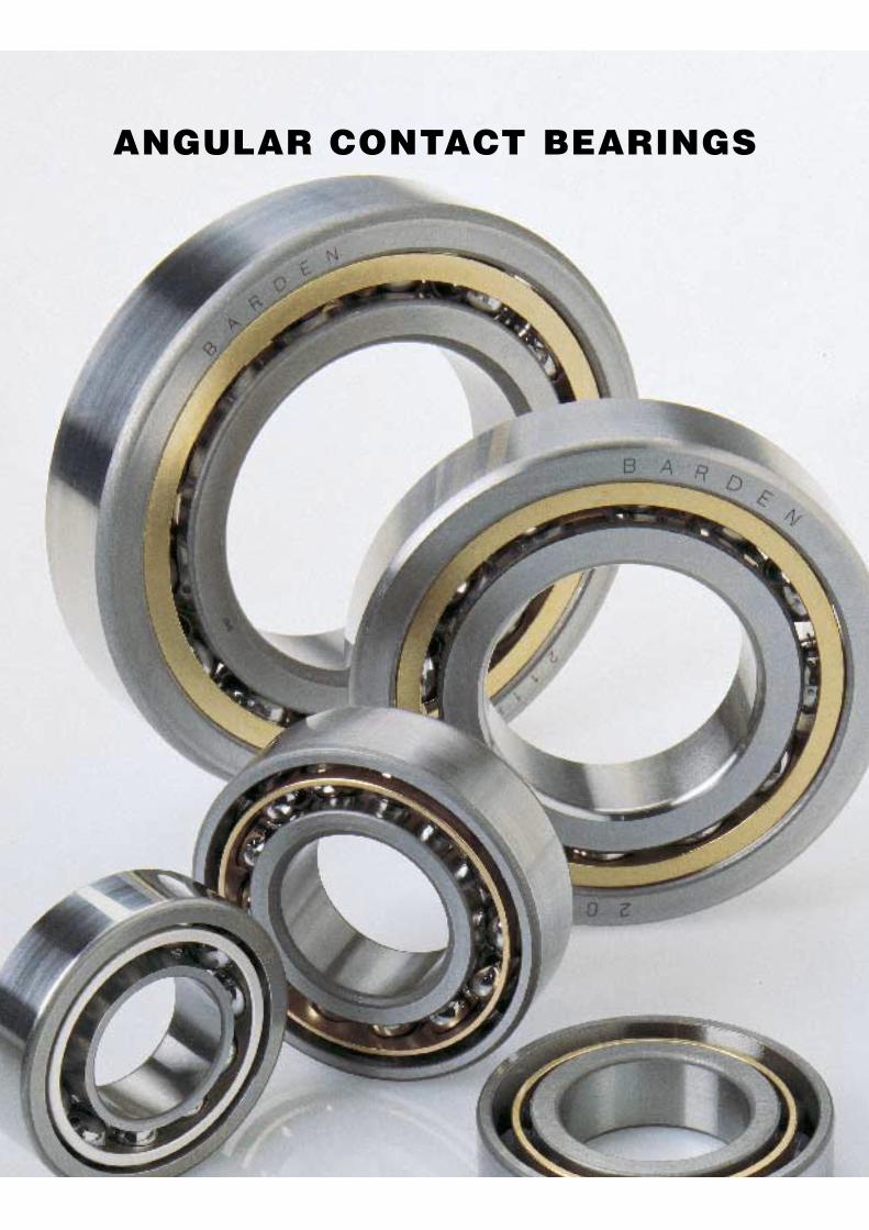
ANGULAR CONTACT BEARINGS
Barden · 36
ANGULAR CONTACT BEARINGS
� This page folds out
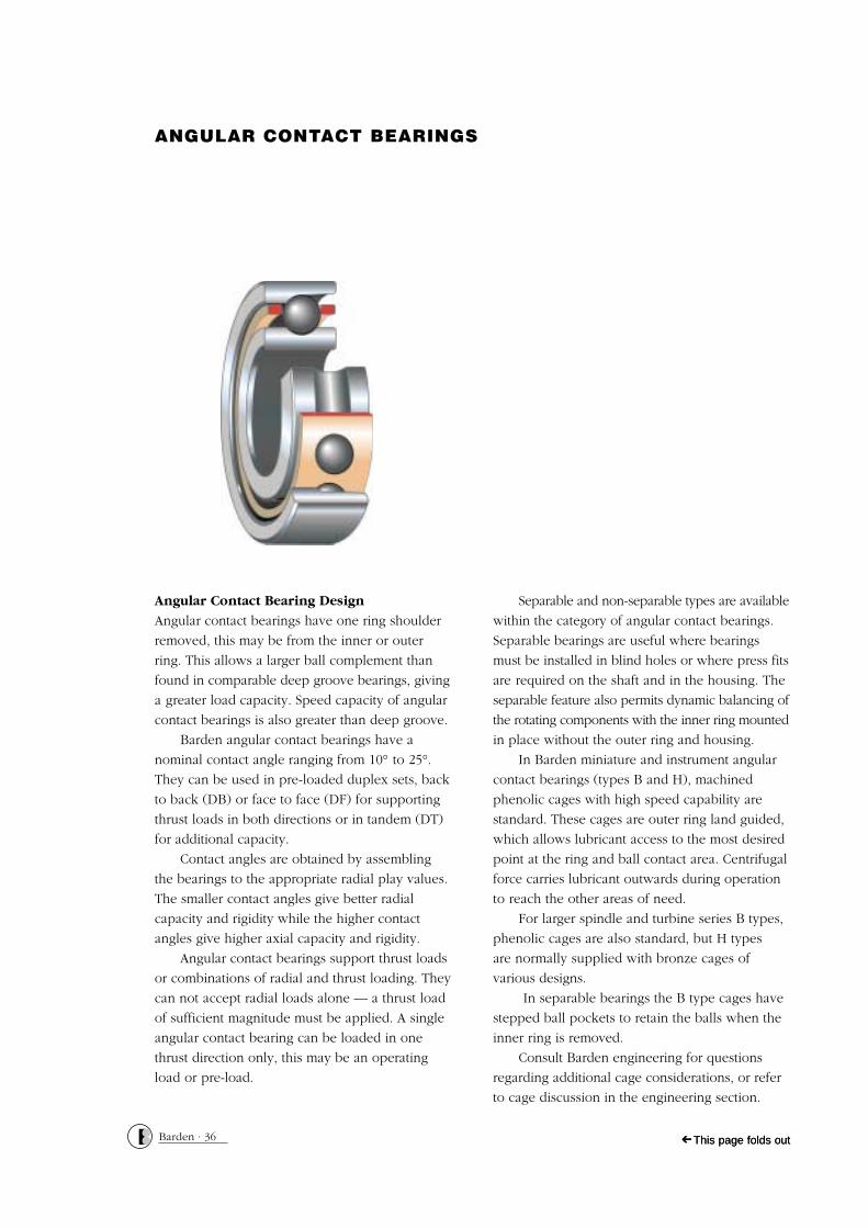
Angular Contact Bearing Design
Angular contact bearings have one ring shoulder
removed, this may be from the inner or outer
ring. This allows a larger ball complement than
found in comparable deep groove bearings, giving
a greater load capacity. Speed capacity of angular
contact bearings is also greater than deep groove.
Barden angular contact bearings have a
nominal contact angle ranging from 10° to 25°.
They can be used in pre-loaded duplex sets, back
to back (DB) or face to face (DF) for supporting
thrust loads in both directions or in tandem (DT)
for additional capacity.
Contact angles are obtained by assembling
the bearings to the appropriate radial play values.
The smaller contact angles give better radial
capacity and rigidity while the higher contact
angles give higher axial capacity and rigidity.
Angular contact bearings support thrust loads
or combinations of radial and thrust loading. They
can not accept radial loads alone — a thrust load
of sufficient magnitude must be applied. A single
angular contact bearing can be loaded in one
thrust direction only, this may be an operating
load or pre-load.
Separable and non-separable types are available
within the category of angular contact bearings.
Separable bearings are useful where bearings
must be installed in blind holes or where press fits
are required on the shaft and in the housing. The
separable feature also permits dynamic balancing of
the rotating components with the inner ring mounted
in place without the outer ring and housing.
In Barden miniature and instrument angular
contact bearings (types B and H), machined
phenolic cages with high speed capability are
standard. These cages are outer ring land guided,
which allows lubricant access to the most desired
point at the ring and ball contact area. Centrifugal
force carries lubricant outwards during operation
to reach the other areas of need.
For larger spindle and turbine series B types,
phenolic cages are also standard, but H types
are normally supplied with bronze cages of
various designs.
In separable bearings the B type cages have
stepped ball pockets to retain the balls when the
inner ring is removed.
Consult Barden engineering for questions
regarding additional cage considerations, or refer
to cage discussion in the engineering section.
� This page folds out

Nomenclature
M 102J JJ X17 R2 C40 0-14
Materials & Special Processes
Radial Runout
Calibration
Special Features
Size & Series
Cage
Radial Play Functional TestDuplexing & Preloading
Lubrication
Materials & Special ProcessesBC – Barrier coating
P – TCP coatingC – Ceramic Balls
30X – ‘X Life Ultra’ ringsS – AISI 440C rings and ballsM – M50 rings and ballsT – T5 rings and T15 ballsV – Denotes Abec 5T for torque
tube and extra thin seriesNo symbol indicates SAE 52100 rings and balls
Sizes & SeriesR_B – Inch series instrument angular
contact bearing with separable relieved inner ring
R_H – Inch series instrument angular contact bearing with non separable relieved outer ring
30B or H – Metric series spindle/turbine configurations as for R series above
100B – Metric series spindle turbine bearing with separable relieved inner ring
100/200/300/1900 H – Metric series spindle/turbine angular contact non separablerelieved outer ring
100/200/300/1900 J – Metric series spindle/ turbine angular contact non separablerelieved inner ring
CagesB – Reinforced phenolic, one piece, designed
to retain the balls in the outer ringH – Reinforced phenolic, one piece , halo design
(H)JB – Bronze machined halo light weight design for optimum capacity
(H)JH – Bronze machined halo, heavier section, centered on ball pitch diameter
(J)JJ – Bronze pressed halo with formed pockets
Special FeaturesLetters ‘X’ or ‘Y’ followed by numbers indicatespecial features. Some of these are now ‘standard’ and appear in the bearing tables.Some commonly used are:X204 – Customer part number marked on bearingX205 – Full of Balls (no cage)Consult Barden Engineering for details.
Duplexing & PreloadsFor duplex sets, letter symbol indicates type ofmounting. If followed by number, numerals indicatemean preload in pounds. Absence of number indicates standard preload.D – Universal mounting. Angular contact duplexsets universally ground have inner and outer ringsof the same width, and can be installed DB, DF or DT.Standard Preloads are indicated by: L – Light, M – Medium and H – Heavy.
Radial RunoutE – Special radial runout consult BardenR – Inner ring marked for high point of
radial runoutR1 – Outer ring marked for high point of
radial runoutR2 – Both rings marked with high point of
radial runout
CalibrationBearings are available with bore and O/D calibratedinto steps of 0.0001", 0.00005" or 0.001mm.
C – Bore and O/D in 0.0001" (0.0025mm) stepsC44 – Bore & O/D in 0.00005" (0.00125mm) steps
O – Is used when no calibration is required, i.e.CXO – bore only calibrated in 0.0001" steps
Groups may be combined, i.e.C4X – Bore is calibrated in 0.00005" steps and
O/D in 0.0001" stepsCM – Special metric calibration in 1 micron
steps (0.001mm), inner ring bore onlyFor further information consult ‘Calibration’ inEngineering Section.
LubricationThe pre-lubrication type is always indicated withinthe bearing number on the packaging.O or OJ numbers denote oilG or GJ numbers denote greasePopular lubricants are listed within ‘Lubrication’ inthe Engineering Section.
Example:
Radial PlayRadial play in angular contact bearings is usuallystandardised by the design either:
to achieve a desired contact angleor
to achieve optimum performance under the typical combined load whilst still remaining assembled for handling and mounting operations
Functional TestAngular contact bearings are not normally subjectto special low torque testing.
Barden · 37
ANGULAR CONTACT BEARINGS
ANGULAR CONTACT BEARINGS
Product Series Descriptions
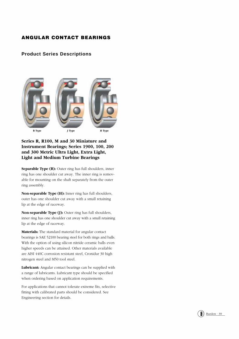
Series R, R100, M and 30 Miniature andInstrument Bearings; Series 1900, 100, 200and 300 Metric Ultra Light, Extra Light,Light and Medium Turbine Bearings
Separable Type (B): Outer ring has full shoulders, inner
ring has one shoulder cut away. The inner ring is remov-
able for mounting on the shaft separately from the outer
ring assembly.
Non-separable Type (H): Inner ring has full shoulders,
outer has one shoulder cut away with a small retaining
lip at the edge of raceway.
Non-separable Type (J): Outer ring has full shoulders,
inner ring has one shoulder cut away with a small retaining
lip at the edge of raceway.
Materials: The standard material for angular contact
bearings is SAE 52100 bearing steel for both rings and balls.
With the option of using silicon nitride ceramic balls even
higher speeds can be attained. Other materials available
are AISI 440C corrosion resistant steel, Cronidur 30 high
nitrogen steel and M50 tool steel.
Lubricant: Angular contact bearings can be supplied with
a range of lubricants. Lubricant type should be specified
when ordering based on application requirements.
For applications that cannot tolerate extreme fits, selective
fitting with calibrated parts should be considered. See
Engineering section for details.
Barden · 39
J Type H TypeB Type
Barden · 40
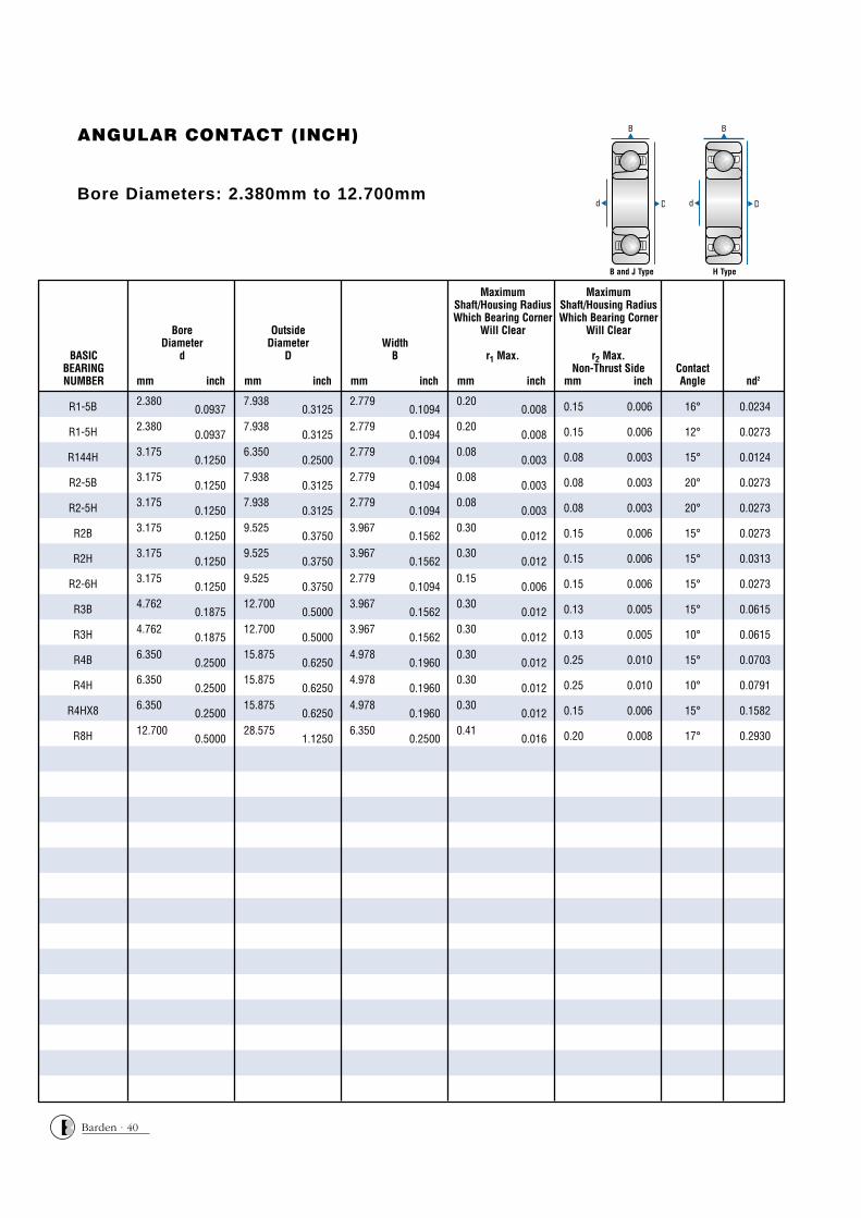
ANGULAR CONTACT (INCH)
Bore Diameters: 2.380mm to 12.700mm
nd2ContactAngle
MaximumShaft/Housing RadiusWhich Bearing Corner
Will Clear
r1 Max.
mm inch
MaximumShaft/Housing RadiusWhich Bearing Corner
Will Clear
r2 Max.Non-Thrust Side
mm inch
WidthB
mm inch
OutsideDiameter
D
mm inch
BoreDiameter
d
mm inch
BoreDiameter
dBASIC
BEARINGNUMBER
R1-5B 2.3800.0937
7.9380.3125
2.7790.1094
0.200.008 0.15 0.006 16° 0.0234
R1-5H 2.3800.0937
7.9380.3125
2.7790.1094
0.200.008 0.15 0.006 12° 0.0273
R144H 3.1750.1250
6.3500.2500
2.7790.1094
0.080.003 0.08 0.003 15° 0.0124
R2-5B 3.1750.1250
7.9380.3125
2.7790.1094
0.080.003 0.08 0.003 20° 0.0273
R2-5H 3.1750.1250
7.9380.3125
2.7790.1094
0.080.003 0.08 0.003 20° 0.0273
R2B 3.1750.1250
9.5250.3750
3.9670.1562
0.300.012 0.15 0.006 15° 0.0273
R2H 3.1750.1250
9.5250.3750
3.9670.1562
0.300.012 0.15 0.006 15° 0.0313
R2-6H 3.1750.1250
9.5250.3750
2.7790.1094
0.150.006 0.15 0.006 15° 0.0273
R3B 4.7620.1875
12.7000.5000
3.9670.1562
0.300.012 0.13 0.005 15° 0.0615
R3H 4.7620.1875
12.7000.5000
3.9670.1562
0.300.012 0.13 0.005 10° 0.0615
R4B 6.3500.2500
15.8750.6250
4.9780.1960
0.300.012 0.25 0.010 15° 0.0703
R4H 6.3500.2500
15.8750.6250
4.9780.1960
0.300.012 0.25 0.010 10° 0.0791
R4HX8 6.3500.2500
15.8750.6250
4.9780.1960
0.300.012 0.15 0.006 15° 0.1582
R8H 12.7000.5000
28.5751.1250
6.3500.2500
0.410.016 0.20 0.008 17° 0.2930
B and J Type H Type
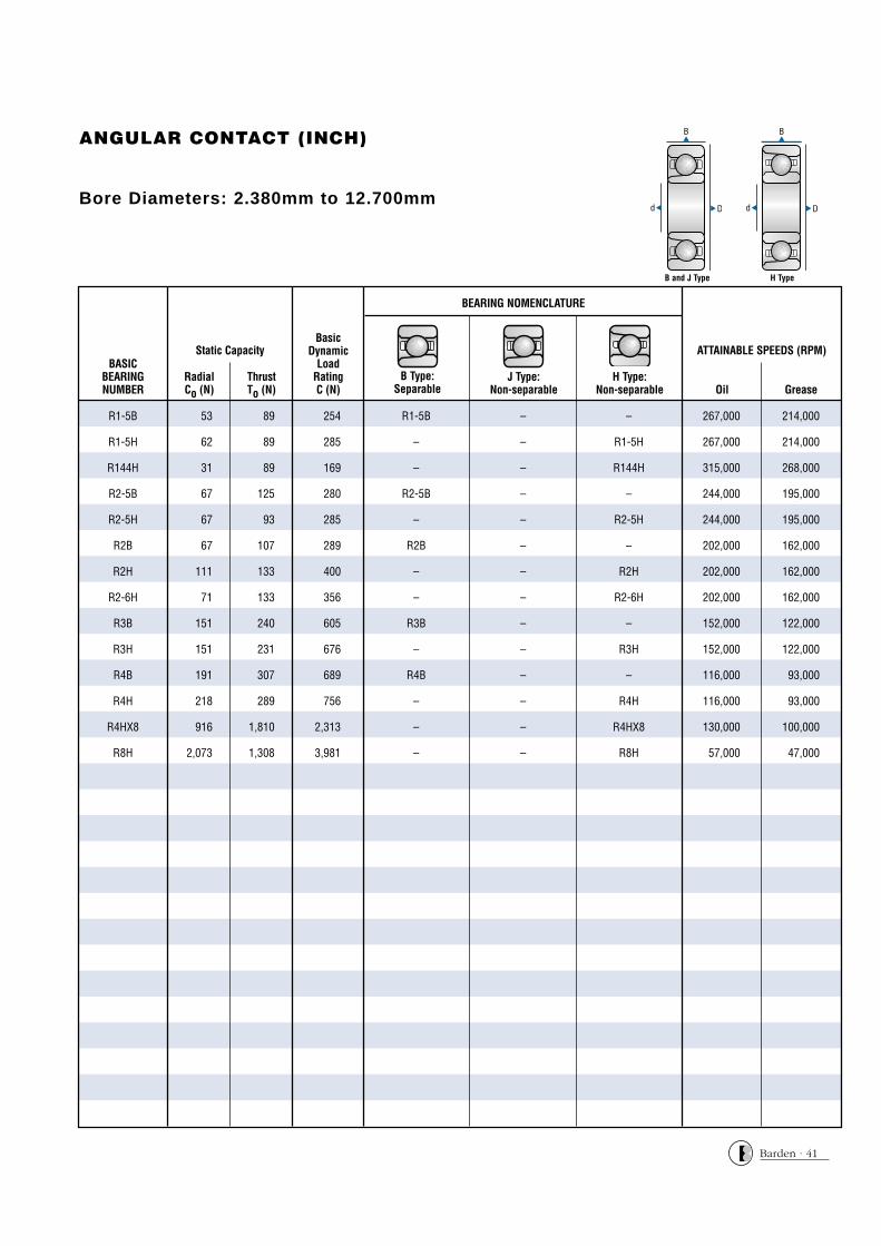
ANGULAR CONTACT (INCH)
Bore Diameters: 2.380mm to 12.700mm
BasicDynamic
LoadRatingC (N)
RadialCo (N)
ThrustTo (N)
BoreDiameter
dBASIC
BEARINGNUMBER
Static Capacity
Oil Grease
ATTAINABLE SPEEDS (RPM)
B Type:Separable
J Type: Non-separable
H Type: Non-separable
BEARING NOMENCLATURE
R1-5B 53 89 254 R1-5B – – 267,000 214,000
R1-5H 62 89 285 – – R1-5H 267,000 214,000
R144H 31 89 169 – – R144H 315,000 268,000
R2-5B 67 125 280 R2-5B – – 244,000 195,000
R2-5H 67 93 285 – – R2-5H 244,000 195,000
R2B 67 107 289 R2B – – 202,000 162,000
R2H 111 133 400 – – R2H 202,000 162,000
R2-6H 71 133 356 – – R2-6H 202,000 162,000
R3B 151 240 605 R3B – – 152,000 122,000
R3H 151 231 676 – – R3H 152,000 122,000
R4B 191 307 689 R4B – – 116,000 93,000
R4H 218 289 756 – – R4H 116,000 93,000
R4HX8 916 1,810 2,313 – – R4HX8 130,000 100,000
R8H 2,073 1,308 3,981 – – R8H 57,000 47,000
B and J Type H Type
Barden · 41
Barden · 42
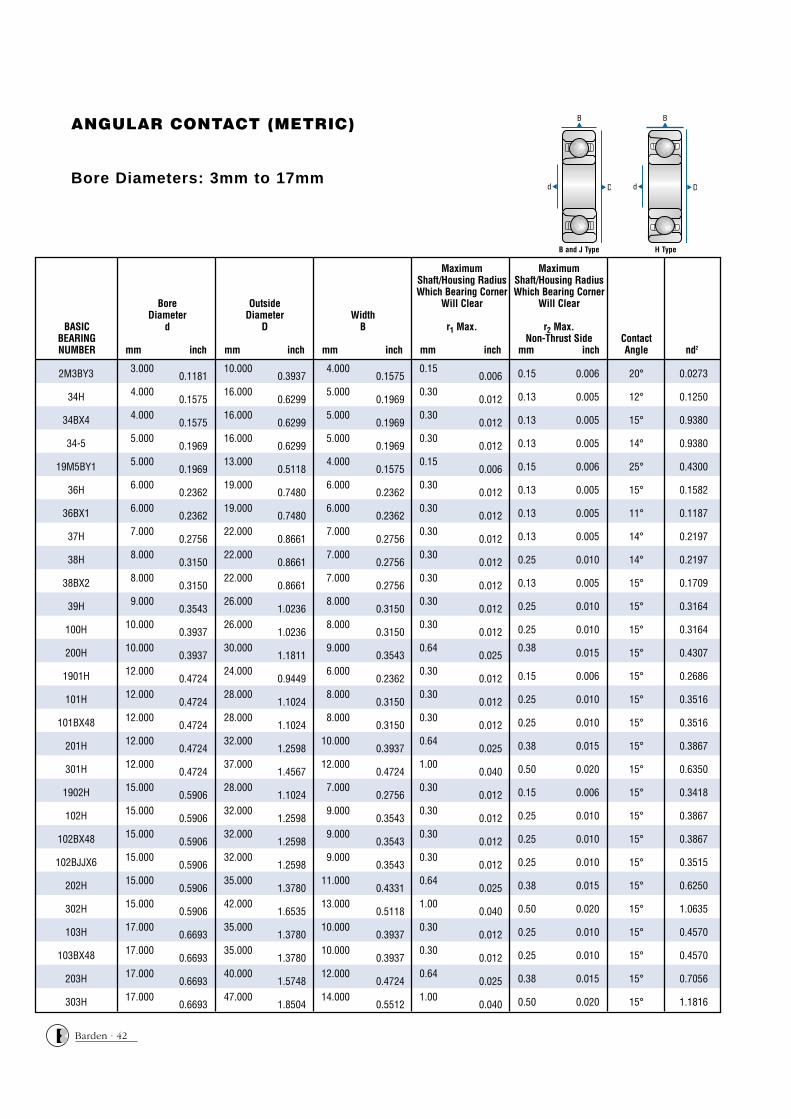
ANGULAR CONTACT (METRIC)
Bore Diameters: 3mm to 17mm
nd2ContactAngle
MaximumShaft/Housing RadiusWhich Bearing Corner
Will Clear
r1 Max.
mm inch
MaximumShaft/Housing RadiusWhich Bearing Corner
Will Clear
r2 Max.Non-Thrust Side
mm inch
WidthB
mm inch
OutsideDiameter
D
mm inch
BoreDiameter
d
mm inch
BoreDiameter
dBASIC
BEARINGNUMBER
2M3BY3 3.0000.1181
10.0000.3937
4.0000.1575
0.150.006 0.15 0.006 20° 0.0273
34H 4.0000.1575
16.0000.6299
5.0000.1969
0.300.012 0.13 0.005 12° 0.1250
34BX4 4.0000.1575
16.0000.6299
5.0000.1969
0.300.012 0.13 0.005 15° 0.9380
34-5 5.0000.1969
16.0000.6299
5.0000.1969
0.300.012 0.13 0.005 14° 0.9380
19M5BY1 5.0000.1969
13.0000.5118
4.0000.1575
0.150.006 0.15 0.006 25° 0.4300
36H 6.0000.2362
19.0000.7480
6.0000.2362
0.300.012 0.13 0.005 15° 0.1582
36BX1 6.0000.2362
19.0000.7480
6.0000.2362
0.300.012 0.13 0.005 11° 0.1187
37H 7.0000.2756
22.0000.8661
7.0000.2756
0.300.012 0.13 0.005 14° 0.2197
38H 8.0000.3150
22.0000.8661
7.0000.2756
0.300.012 0.25 0.010 14° 0.2197
38BX2 8.0000.3150
22.0000.8661
7.0000.2756
0.300.012 0.13 0.005 15° 0.1709
39H 9.0000.3543
26.0001.0236
8.0000.3150
0.300.012 0.25 0.010 15° 0.3164
100H 10.0000.3937
26.0001.0236
8.0000.3150
0.300.012 0.25 0.010 15° 0.3164
200H 10.0000.3937
30.0001.1811
9.0000.3543
0.640.025
0.38 0.015 15° 0.4307
1901H 12.0000.4724
24.0000.9449
6.0000.2362
0.300.012 0.15 0.006 15° 0.2686
101H 12.0000.4724
28.0001.1024
8.0000.3150
0.300.012 0.25 0.010 15° 0.3516
101BX48 12.0000.4724
28.0001.1024
8.0000.3150
0.300.012 0.25 0.010 15° 0.3516
201H 12.0000.4724
32.0001.2598
10.0000.3937
0.640.025 0.38 0.015 15° 0.3867
301H 12.0000.4724
37.0001.4567
12.0000.4724
1.000.040 0.50 0.020 15° 0.6350
1902H 15.0000.5906
28.0001.1024
7.0000.2756
0.300.012 0.15 0.006 15° 0.3418
102H 15.0000.5906
32.0001.2598
9.0000.3543
0.300.012 0.25 0.010 15° 0.3867
102BX48 15.0000.5906
32.0001.2598
9.0000.3543
0.300.012 0.25 0.010 15° 0.3867
102BJJX6 15.0000.5906
32.0001.2598
9.0000.3543
0.300.012 0.25 0.010 15° 0.3515
202H 15.0000.5906
35.0001.3780
11.0000.4331
0.640.025 0.38 0.015 15° 0.6250
302H 15.0000.5906
42.0001.6535
13.0000.5118
1.000.040 0.50 0.020 15° 1.0635
103H 17.0000.6693
35.0001.3780
10.0000.3937
0.300.012 0.25 0.010 15° 0.4570
103BX48 17.0000.6693
35.0001.3780
10.0000.3937
0.300.012 0.25 0.010 15° 0.4570
203H 17.0000.6693
40.0001.5748
12.0000.4724
0.640.025 0.38 0.015 15° 0.7056
303H 17.0000.6693
47.0001.8504
14.0000.5512
1.000.040 0.50 0.020 15° 1.1816
B and J Type H Type
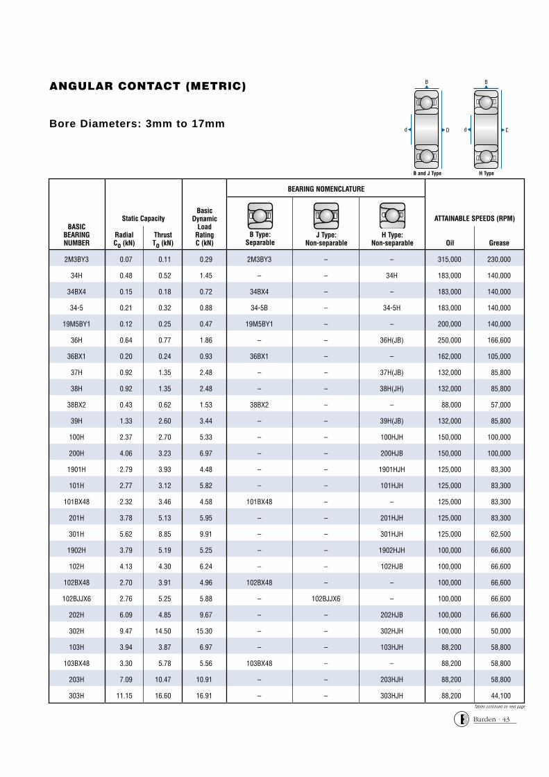
ANGULAR CONTACT (METRIC)
Bore Diameters: 3mm to 17mm
Tables continued on next page
BasicDynamic
LoadRatingC (kN)
RadialCo (kN)
ThrustTo (kN)
BoreDiameter
dBASIC
BEARINGNUMBER
Static Capacity
Oil Grease
ATTAINABLE SPEEDS (RPM)
2M3BY3 0.07 0.11 0.29 2M3BY3 – – 315,000 230,000
34H 0.48 0.52 1.45 – – 34H 183,000 140,000
34BX4 0.15 0.18 0.72 34BX4 – – 183,000 140,000
34-5 0.21 0.32 0.88 34-5B – 34-5H 183,000 140,000
19M5BY1 0.12 0.25 0.47 19M5BY1 – – 200,000 140,000
36H 0.64 0.77 1.86 – – 36H(JB) 250,000 166,600
36BX1 0.20 0.24 0.93 36BX1 – – 162,000 105,000
37H 0.92 1.35 2.48 – – 37H(JB) 132,000 85,800
38H 0.92 1.35 2.48 – – 38H(JH) 132,000 85,800
38BX2 0.43 0.62 1.53 38BX2 – – 88,000 57,000
39H 1.33 2.60 3.44 – – 39H(JB) 132,000 85,800
100H 2.37 2.70 5.33 – – 100HJH 150,000 100,000
200H 4.06 3.23 6.97 – – 200HJB 150,000 100,000
1901H 2.79 3.93 4.48 – – 1901HJH 125,000 83,300
101H 2.77 3.12 5.82 – – 101HJH 125,000 83,300
101BX48 2.32 3.46 4.58 101BX48 – – 125,000 83,300
201H 3.78 5.13 5.95 – – 201HJH 125,000 83,300
301H 5.62 8.85 9.91 – – 301HJH 125,000 62,500
1902H 3.79 5.19 5.25 – – 1902HJH 100,000 66,600
102H 4.13 4.30 6.24 – – 102HJB 100,000 66,600
102BX48 2.70 3.91 4.96 102BX48 – – 100,000 66,600
102BJJX6 2.76 5.25 5.88 – 102BJJX6 – 100,000 66,600
202H 6.09 4.85 9.67 – – 202HJB 100,000 66,600
302H 9.47 14.50 15.30 – – 302HJH 100,000 50,000
103H 3.94 3.87 6.97 – – 103HJH 88,200 58,800
103BX48 3.30 5.78 5.56 103BX48 – – 88,200 58,800
203H 7.09 10.47 10.91 – – 203HJH 88,200 58,800
303H 11.15 16.60 16.91 – – 303HJH 88,200 44,100
B Type:Separable
J Type: Non-separable
H Type: Non-separable
BEARING NOMENCLATURE
B and J Type H Type
Barden · 43

Barden · 44
ANGULAR CONTACT (METRIC)
Bore Diameters: 20mm to 50mm
nd2ContactAngle
MaximumShaft/Housing RadiusWhich Bearing Corner
Will Clear
r1 Max.
mm inch
MaximumShaft/Housing RadiusWhich Bearing Corner
Will Clear
r2 Max.Non-Thrust Side
mm inch
WidthB
mm inch
OutsideDiameter
D
mm inch
BoreDiameter
d
mm inch
BoreDiameter
dBASIC
BEARINGNUMBER
104H 20.0000.7874
42.0001.6535
12.0000.4724
0.640.025 0.38 0.015 15° 0.6875
104BX48 20.0000.7874
42.0001.6535
12.0000.4724
0.640.025 0.38 0.015 15° 0.6875
204H 20.0000.7874
47.0001.8504
14.0000.5512
1.000.040 0.50 0.020 15° 0.9766
304H 20.0000.7874
52.0002.0472
15.0000.5906
1.000.040 0.50 0.020 15° 1.4854
1905H 25.0000.9843
42.0001.6535
9.0000.3543
0.300.012 0.25 0.010 15° 0.7656
105H 25.0000.9843
47.0001.8504
12.0000.4724
0.640.025 0.38 0.015 15° 0.8125
105BX48 25.0000.9843
47.0001.8504
12.0000.4724
0.640.025 0.38 0.015 15° 0.8125
205H 25.0000.9843
52.0002.0472
15.0000.5906
1.000.040 0.50 0.020 15° 1.0742
305H 25.0000.9843
62.0002.4409
17.0000.6693
1.000.040 0.50 0.020 15° 2.1973
106H 30.0001.1811
55.0002.1654
13.0000.5118
1.000.040 0.50 0.020 15° 1.1074
106BX48 30.0001.1811
55.0002.1654
13.0000.5118
1.000.040 0.50 0.020 15° 1.1074
206H 30.0001.1811
62.0002.4409
16.0000.6299
1.000.040 0.50 0.020 15° 1.8154
306H 30.0001.1811
72.0002.8346
19.0000.7480
1.000.040 1.00 0.040 15° 2.8223
1907H 35.0001.3780
55.0002.1654
10.0000.3937
0.640.025 0.38 0.015 15° 1.1875
107H 35.0001.3780
62.0002.4409
14.0000.5512
1.000.040 0.50 0.020 15° 1.4648
107BX48 35.0001.3780
62.0002.4409
14.0000.5512
1.000.040 0.50 0.020 15° 1.4648
207H 35.0001.3780
72.0002.8346
17.0000.6693
1.000.040 0.50 0.020 15° 2.2969
307H 35.0001.3780
80.0003.1496
21.0000.8268
1.500.060 0.76 0.030 15° 3.4805
108H 40.0001.5748
68.0002.6772
15.0000.5906
1.000.040 0.50 0.020 15° 1.6602
108BX48 40.0001.5748
68.0002.6772
15.0000.5906
1.000.040 0.50 0.020 15° 1.6602
208H 40.0001.5748
80.0003.1496
18.0000.7087
1.000.040 0.50 0.020 15° 2.6367
308H 40.0001.5748
90.0003.5433
23.0000.9055
1.500.060 0.76 0.030 15° 1.0742
109H 45.0001.7717
75.0002.9528
16.0000.6299
1.000.040 0.50 0.020 15° 2.2500
209H 45.0001.7717
85.0003.3465
19.0000.7480
1.000.040 0.50 0.020 15° 2.8564
309H 45.0001.7717
100.0003.9370
25.0000.9843
1.500.060 0.76 0.030 15° 5.1992
110H 50.0001.9685
80.0003.1496
16.0000.6299
1.000.040 0.50 0.020 15° 2.5313
110BX48 50.0001.9685
80.0003.1496
16.0000.6299
1.000.040 0.50 0.020 15° 2.5313
210H 50.0001.9685
90.0003.5433
20.0000.7874
1.000.040 0.50 0.020 15° 3.5000
B and J Type H Type
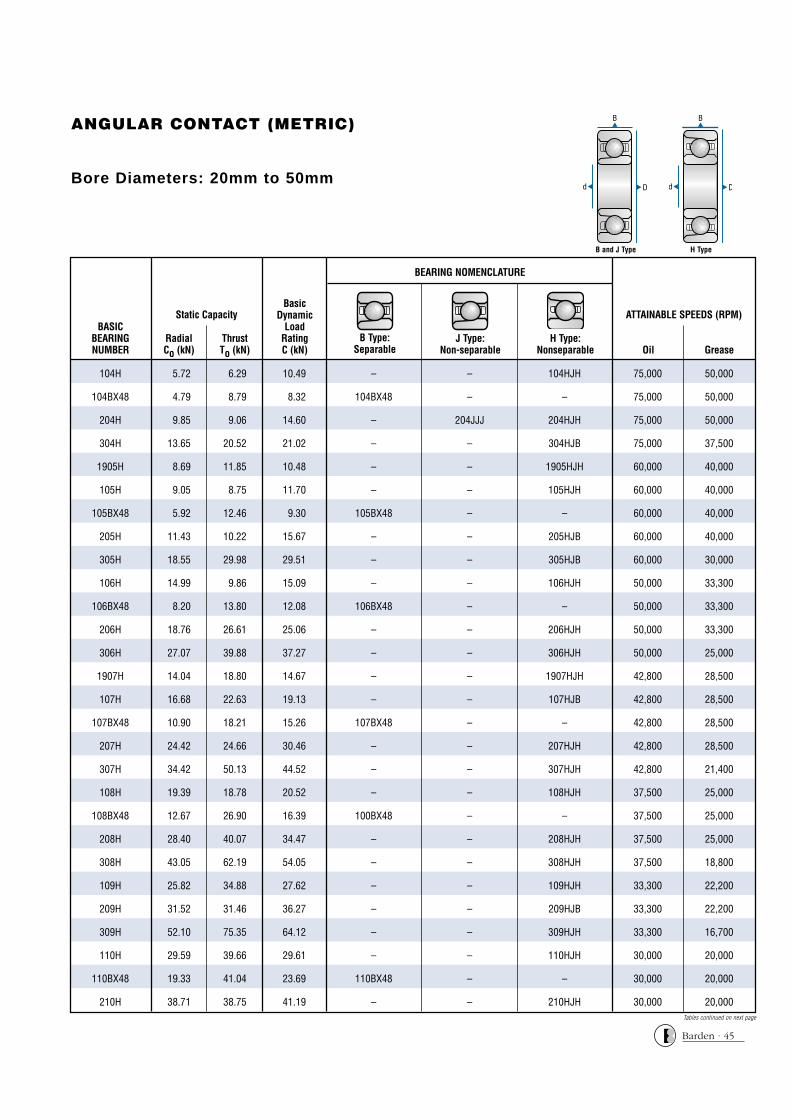
ANGULAR CONTACT (METRIC)
Bore Diameters: 20mm to 50mm
Tables continued on next page
BasicDynamic
LoadRatingC (kN)
RadialCo (kN)
ThrustTo (kN)
BoreDiameter
dBASIC
BEARINGNUMBER
Static Capacity
Oil Grease
ATTAINABLE SPEEDS (RPM)
104H 5.72 6.29 10.49 – – 104HJH 75,000 50,000
104BX48 4.79 8.79 8.32 104BX48 – – 75,000 50,000
204H 9.85 9.06 14.60 – 204JJJ 204HJH 75,000 50,000
304H 13.65 20.52 21.02 – – 304HJB 75,000 37,500
1905H 8.69 11.85 10.48 – – 1905HJH 60,000 40,000
105H 9.05 8.75 11.70 – – 105HJH 60,000 40,000
105BX48 5.92 12.46 9.30 105BX48 – – 60,000 40,000
205H 11.43 10.22 15.67 – – 205HJB 60,000 40,000
305H 18.55 29.98 29.51 – – 305HJB 60,000 30,000
106H 14.99 9.86 15.09 – – 106HJH 50,000 33,300
106BX48 8.20 13.80 12.08 106BX48 – – 50,000 33,300
206H 18.76 26.61 25.06 – – 206HJH 50,000 33,300
306H 27.07 39.88 37.27 – – 306HJH 50,000 25,000
1907H 14.04 18.80 14.67 – – 1907HJH 42,800 28,500
107H 16.68 22.63 19.13 – – 107HJB 42,800 28,500
107BX48 10.90 18.21 15.26 107BX48 – – 42,800 28,500
207H 24.42 24.66 30.46 – – 207HJH 42,800 28,500
307H 34.42 50.13 44.52 – – 307HJH 42,800 21,400
108H 19.39 18.78 20.52 – – 108HJH 37,500 25,000
108BX48 12.67 26.90 16.39 100BX48 – – 37,500 25,000
208H 28.40 40.07 34.47 – – 208HJH 37,500 25,000
308H 43.05 62.19 54.05 – – 308HJH 37,500 18,800
109H 25.82 34.88 27.62 – – 109HJH 33,300 22,200
209H 31.52 31.46 36.27 – – 209HJB 33,300 22,200
309H 52.10 75.35 64.12 – – 309HJH 33,300 16,700
110H 29.59 39.66 29.61 – – 110HJH 30,000 20,000
110BX48 19.33 41.04 23.69 110BX48 – – 30,000 20,000
210H 38.71 38.75 41.19 – – 210HJH 30,000 20,000
B Type:Separable
J Type: Non-separable
H Type: Nonseparable
BEARING NOMENCLATURE
B and J Type H Type
Barden · 45
Barden · 46
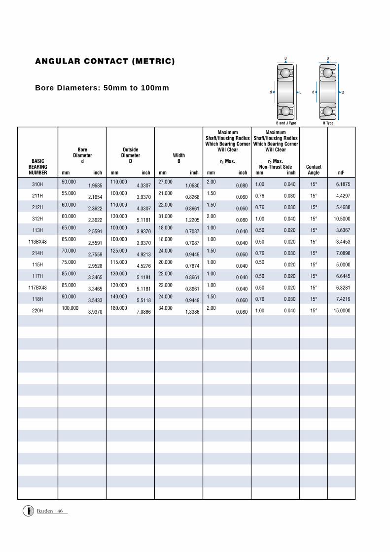
ANGULAR CONTACT (METRIC)
Bore Diameters: 50mm to 100mm
nd2ContactAngle
MaximumShaft/Housing RadiusWhich Bearing Corner
Will Clear
r1 Max.
mm inch
MaximumShaft/Housing RadiusWhich Bearing Corner
Will Clear
r2 Max.Non-Thrust Side
mm inch
WidthB
mm inch
OutsideDiameter
D
mm inch
BoreDiameter
d
mm inch
BoreDiameter
dBASIC
BEARINGNUMBER
310H 50.0001.9685
110.0004.3307
27.0001.0630
2.000.080 1.00 0.040 15° 6.1875
211H 55.0002.1654
100.0003.9370
21.0000.8268
1.500.060 0.76 0.030 15° 4.4297
212H 60.0002.3622
110.0004.3307
22.0000.8661
1.500.060 0.76 0.030 15° 5.4688
312H 60.0002.3622
130.0005.1181
31.0001.2205
2.000.080 1.00 0.040 15° 10.5000
113H 65.0002.5591
100.0003.9370
18.0000.7087
1.000.040 0.50 0.020 15° 3.6367
113BX48 65.0002.5591
100.0003.9370
18.0000.7087
1.000.040 0.50 0.020 15° 3.4453
214H 70.0002.7559
125.0004.9213
24.0000.9449
1.500.060 0.76 0.030 15° 7.0898
115H 75.0002.9528
115.0004.5276
20.0000.7874
1.000.040
0.50 0.020 15° 5.0000
117H 85.0003.3465
130.0005.1181
22.0000.8661
1.000.040 0.50 0.020 15° 6.6445
117BX48 85.0003.3465
130.0005.1181
22.0000.8661
1.000.040 0.50 0.020 15° 6.3281
118H 90.0003.5433
140.0005.5118
24.0000.9449
1.500.060 0.76 0.030 15° 7.4219
220H 100.0003.9370
180.0007.0866
34.0001.3386
2.000.080 1.00 0.040 15° 15.0000
B and J Type H Type

ANGULAR CONTACT (METRIC)
Bore Diameters: 50mm to 100mm
BasicDynamic
LoadRatingC (kN)
RadialCo (kN)
ThrustTo (kN)
BoreDiameter
dBASIC
BEARINGNUMBER
Static Capacity
Oil Grease
ATTAINABLE SPEEDS (RPM)
310H 62.31 89.55 75.11 – – 310HJH 30,000 20,000
211H 48.71 67.25 52.96 – – 211HJH 27,200 18,000
212H 60.04 60.34 64.05 – – 212HJH 25,000 16,600
312H 87.77 132.05 105.28 – – 312HJH 25,000 12,500
113H 43.32 47.35 40.05 – – 113HJH 23,000 15,300
113BX48 26.79 57.05 30.96 113BX48 – – 23,000 15,300
214H 78.73 108.09 79.38 – – 214HJH 21,400 14,200
115H 59.65 79.41 52.66 – – 115HJH 20,000 13,300
117H 79.33 105.14 67.20 – – 117HJH 17,600 11,700
117BX48 49.35 105.16 52.09 117BX48 – – 17,600 11,700
118H 87.95 117.80 76.40 – – 118HJH 16,600 11,100
220H 166.01 229.28 155.92 – – 220HJH 15,000 10,000
B and J Type H Type
B Type:Separable
J Type: Non-separable
H Type: Non-separable
BEARING NOMENCLATURE
Barden · 47