Angular Contact Ball Bearings 40° - LaakeriCenter | Uutiset · · 2010-04-07IBC angular contact...
20
Angular Contact Ball Bearings 40° TI-I-4044.0 / E
Transcript of Angular Contact Ball Bearings 40° - LaakeriCenter | Uutiset · · 2010-04-07IBC angular contact...

Angular Contact Ball Bearings 40°TI-I-4044.0 / E

LLooccaattiioonn wwiitthh TTrraaddiittiioonn
The headquarters in Solms-Oberbielis centrally located in Germany close to the North/South and East/West highways whichalso provides for a central location in Europe.The international Airport Frankfurt approx.80 km away serves as a worldwide link.
FF ll eexxiibbllee aanndd RReelliiaabbllee
In the middle of 1996 we opened the central computer controlled high shelf warehouse withmore than 2.000 pallet places.It is used for finsihed andsemi-finished products as wellas for large bearings.This is in addition to our existingtwo-storage computer controlledservice warehouse also with more than 2.500 storage places.
Both warehouse systemsprovide together with our distribution centre and communication network preciselogistics and a worldwideunequaled reliability.
PP rreecciissiioonn wwiitthh FFuuttuurree .. .. ..
We are future orientated.We have the creativity and vision to perform and provide.TThhiiss iiss oouurr eexxaacctt pprreesseennttaattiioonn ttoo ssoolluuttiioonnss wwiitthh pprreecciissiioonn..
Headquarter of the IBC Wälzlager GmbH at the industrial area of Solms-Oberbiel
Precise Logistics provide an unequaled worldwide reliability
New plant in Asslar
Central Computer Controlled High Shelf Warehouse – Middle 1996

IBC INDUSTRIAL BEARINGS AND COMPONENTS 3
Single Row Angular Contact Ball Bearings of series BEwith 40° contact angle To meet all the different technical applications and operatingconditions, accurate solutions are required. Only an extensiverange of angular contact ball bearings fulfil the diversity ofrequirements such as high rotational speed and load carryingcapacity, running accuracy, stiffness, as well as combinedradial and axial load at low heat generation.Single Row 40° angular contact ball bearings can accommo-date radial and axial loads in only one direction.(>See picture 44-101)
Load acting of 40° angular contact ball bearing 44-101
Also external radial loads are creating axial force within thebearing, which has to be compensated by a further bearing.Normally there are two angular contact ball bearings adjustedagainst each other.
There are typical fields of applications with combined radialand axial load within gears, gear motors, fans, compressors,screw compressors, ventilators, pumps, textile machines,printing machines, conveyors where shaft guidance free ofclearance should be achieved.Distinguishing marks of IBC 40° angular contact ball bearingsare quiet running, low friction, high rotational speed and along lifespan. Especially usage in pumps or compressors arecreating combined loads at high rotational speed often underunfavourable lubrication circumstances and heavy contamina-tion.
IBC 40° angular contact ball bearings of BE series, with eachone high and one low shoulder at the bearing rings are non-separable. In comparison to series B, load carrying capacitycould have been increased due to larger balls.
The larger the axial load carrying capacity the larger the sizeof contact angle, which is including the conjunction line ofboth contact points between balls and raceways with the radi-al axis and from which the load is transferred from one race-way to the other.
DimensionsThe main dimensions of the IBC single row angular contactball bearings are according to DIN 616, ISO 15 and DIN 628,part 1.
SeriesIBC angular contact ball bearings are available in variousdesigns. 70BE, 72BE, 73BE (> see picture 44-102). Furthervariations with other preloads are deliverable on request.
Comparison of cross sections of 40° Angular Contact Ball Bearings 44-102
MaterialsBearing rings and rolling elements are made of bearing steel100Cr6 (1.3505) corresponding with SAE52100 and SUJ2.
Heat treatmentIBC angular contact ball bearings are dimensionally stableand can be used at operating temperatures of up to 130°C. Inaddition to higher values heat treatment for higher tempera-tures are available on request.
CagesDepending on bearing design and size, various types ofcages are deliverable.
P Solid window cage PA6.6 Polyamide glass fibre reinforced, applicable up to 120 °C
M Solid brass cageJ Steel sheetK PEEK cage, glass fibre reinforced, applicable up to 200 °C,
in case of high rotational speed up to max. 150 °C
Cage designs 44-103

4 IBC WÄLZLAGER GMBH
Remarks:If the bearings are lubricated with oil, any additives containedin the oil may reduce the PA6.6 cage service life. At tempera-tures over 120°C steel cages, PEEK or brass cages shouldbe used.When using in ammonia surroundings such as freezing-appa-ratuses, bearings with brass cages are not suitable.
Sealed versionsIBC supplies types of angular contact ball bearings, which aresealed on both sides. The bearings are filled with lithium soapgrease with mineral basic oil.Bearings with special grease are recognized by suffix. IBCsupplies also angular contact ball bearings with shields orseals on one or both sides. Bearings with basic sealing(2RSZ) can be used within a temperature range between–10°C up to +120°C. Sealing with fluor caoutchouc (Viton) isavailable on request.
Lubricated open bearingsAlso open bearings could already be delivered with grease.Lubricants are recognized by suffix.
Hybrid bearingsBearings with ceramic balls made of silicon nitride Si3N4 areapplicable for current insulation.Due to low specific weight of ceramic balls and the resultinglow centrifugal forces, an increase in rotational speed of up to35% is possible in comparison to steel balls. Thus the dynam-ic load rating is kept and the static load rating is reduced to70%.
Coated Bearings(Prefix AC)ATCoat enables a bearing to be higher resistant against cor-rosion, wear and allows an increase of speed. This is causedby thin dense chromium coat. The special topographic surfacealso increases the ability of a bearing to withstand emergencysituations. All these characteristics lead to use ATCoated IBCbearings under uncomfortable lubrication conditions.
These conditions are for example explained below:– when it is impossible to use a lubricant,– when it is only possible to use a low viscous lubricant,
which cannot create a separating film,– when movement is not a complete rotation, where the lubri-
cant film will not remain,– when the bearing is unloaded and the rolling elements start
to slide,– when in case of high acceleration or braking the rolling ele-
ments start so slide.
The ATCoat bearings are an opportunity to corrosion resistantbearings. The protective coat in connection with ceramic ballsprovides very good technical features (prefix ACC).
Designs
1) Single bearingsSingle bearings are suitable where only one bearing per bear-ing location is used. These single bearings are positioned in acertain distance to each other.A specially defined tightening torque via a locknut or a flangemakes adjusting of preload or axial clearance. In case of suchbearing arrangements single row angular contact ball bear-ings have to be adjusted against each other until the neces-sary preload or axial clearance is reached. The right adjust-ment of both single bearings is quite essential to guaranteethe bearing’s functionality. Otherwise lifespan would bereduced caused by higher friction loss and thus resultinghigher operating temperatures. Even running noises or move-ment between balls and raceway may occur and thus com-plete load carrying capacity could not be fully used.
2) Universal bearings for mounting in pairsSingle row angular contact ball bearings for universal designare intended for mounting in pairs in T-arrangements (tandem)in such cases when load carrying capacity is not sufficientenough, respectively the bearing arrangements have to carryaxial load in both directions (O- or X-arrangement).The uni-versal bearings have a defined ground stick-out S at thelateral faces of the inner and outer ring. This enables adjust-ment without shims.(> See Picture 44-104 a) with positive and b) with negativeclearance, which means preload.)
44-104
Axial clearance and preload classes are given in the table onpage 5. The sequence of letters A, B, O, L, M signifies theamount of high axial play to medium preload.
S-
Picture a Picture b

IBC INDUSTRIAL BEARINGS AND COMPONENTS 5
The mentioned figures show the non-mounted bearingarrangements of two bearings without measuring load.
Universally ground bearings show the same protruding dis-tance of inner to outer ring on both sides and therefore areapplicable for any O-, X- or T-arrangements.
ArrangementsAccommodation of axial load in both directions enables O-and X-arrangement. Due to contact lines meeting in apexesoutside of the two bearings, O-arrangement is more suitablefor accommodation of tilting moments, considering that bear-ing sets in such arrangements result in a relatively rigid bear-ing arrangement. Comparing to O-arrangement, the contactlines of X-arrangement are converging within the two bear-ings.Considering the above, the X-arrangement is less rigid.In case of main load in one direction bearings could bemounted in tandem arrangement. In case of occasionalchange of load direction a counter acting bearing would benecessary. (Please refer to column “radial clearance and pre-load”.)
Bearing arrangements 44-105
InclinationMisalignment should be avoided. According to arrangement atmax. 2 angular minutes. Inclination is leading to a certainseizure, higher running noise and reduces lifetime.Whereas X-arrangement is less delicate than O-arrangement.
Clearance and preloadUnder appropriate operating conditions and reference speed,very low preload is optional to reach regular and free rolling of elements. Perfect rolling is granted with load distributionFa/Fr > 1.That means, in stationary (cold) conditions, bearings are usedwith minimum internal clearance as under operating condi-tions the inner rings are warming up more than the outer ringsand thus clearance is becoming smaller, respectively preloadis becoming larger.Tight fits for shaft and housing are using up further clearance.In case of high operating clearance, load capacity of the bear-ings is not completely used.In case of unidirectional load in O-and X-arrangement, furtherconsiderations should be observed.The counter bearings should not mainly be discharged tem-porary, as within the discharged bearing unfavourable slidingof balls may happen. This may influence the noise, lubricantfilm, load on cage and lifespan. Light preload or a clearancefree solution should be chosen.
Bearing arrangements with axial clearance and axial preload 44-200
O-arrangement X-arrangement
Tandem-O-arrangementTandem-arrangement
a) with axial clearance: in O-arrangement
axial preload
axial clearance
in X-arrangement
b) with axial preload: in O-arrangement in X-arrangement
axial preload
axial clearance
Bore diameter UA UB UO UL UM UHSeries max. min. max. min. max. min. min. max. min. max. min. max.
over incl. [μm] [μm] [μm] [μm] [μm] [μm]
10 – 18 72 31 23 19 11 6 –2 2 –6 –4 –12 –8 –1673 33 25 21 13 8 –4 4 –8 –6 –14 –10 –1870 38 30 21 13 4 0 0 –4 –2 –10 –6 –14
18 – 30 72 40 32 23 15 6 –2 2 –6 –4 –12 –8 –1673 42 34 25 17 8 –4 4 –8 –6 –14 –10 –1870 47 39 25 17 4 0 0 –4 –2 –10 –6 –14
30 – 50 72 49 41 27 19 6 –2 2 –6 –4 –12 –8 –1673 51 43 29 21 8 –4 4 –8 –6 –14 –10 –18
50 – 8072 60 48 34 22 9 –3 3 –9 –6 –18 –12 –2473 62 50 36 24 11 –5 5 –11 –8 –20 –14 –26
80 – 12072 67 55 38 26 9 –3 3 –9 –6 –18 –12 –2473 69 57 40 28 11 –5 5 –11 –8 –20 –14 –26
120 – 18072 73 61 41 29 9 –3 3 –9 –6 –18 –12 –2473 75 63 43 31 11 –5 5 –11 –8 –20 –14 –26
180 – 25072 90 74 51 35 12 –4 4 –12 –8 –24 –16 –3273 92 76 53 37 14 –6 6 –14 –10 –26 –18 –34
44-201Axial clearance and preload of IBC 40° angular contact ball bearings (pair arrangements)

6 IBC WÄLZLAGER GMBH
Fits for point and circumferential loadsFits mainly influence the clearance or preload and thus thefollowing information should be observed. First of all it has tobe detected which rings accommodate rotating load undwhich point load. Rings with point load are less critical, asthey are only lightly clamped on the counter part. In this way acertain area of the ring diameter is always loaded. The largerthe shocks and load are, the stronger the fits should be.Scheme point load und circumferential load (> see picture 40-300).
Point load and circumferential load 40-300
The light fits are used for lighter loads each up to 0.08 · C, thetighter for higher load ratio.Strong fits and temperature drop between the inner and outerring result in reduction of radial and axial clearance and hasto be considered accordingly.The fits should be adjusted according to the required preloadwhen operating temperature is reached. For hollow shafts andthin-walled housings stronger fits should be taken.
The factor for radial clearance is approximately 0.85 x axialclearance.
Reduction of radial clearance by fits and operating conditionsThe radial clearance is approximately reduced by the follow-ing equation:
Sreff = So – (Sint + ST) [mm] [1.0]
Sreff Effective radial operational clearanceSo Clearance before mountingSint Reduced clearance due to interferenceST Reduced clearance due to temperature differences
between inner and outer ring
After mounting the following clearance appears:
Sm = So – Sint [1.1]
Sint = Inti · fi + Into · fo [mm] [1.2]
Inti Interference inner ringInto Interference outer ringfi Reduction factor inner ringfo Reduction factor outer ring
Guidelines:
fi Solid shaft 0.8fo Steel or cast iron housing 0.7fi Hollow shaft 0.6fo Light metal housing 0.5
fi and fo are depending on roughness and diameter of bearingrings, respectively the diameter of the hollow shaft. Due torestricted possibility of temperature reduction and small sur-face and frequent over-rolling of bearings elements, there is atemperature difference of 5 – 10 K during operating. Whenworking with cold or hot mediums this value will be changedaccordingly.
ST = α ΔT dm [mm] [1.3]
α Expansion value of bearing steel 12 · 10–6/KΔT Temperature difference inner and outer ringdm Mean bearing diameter
inner ring stands stillload direction unchanged
Inner ring
Point loadouter ring rotatingload direction unchanged
Outer ring
Circumferential load
outer ring stands stillload direction rotatingwith inner ring
Circumferential load
inner ring rotatingload direction rotating with inner ring
Point load
outer ring rotatingload direction rotatingwith outer ring
Point load
inner ring stands stillload direction rotatingwith outer ring
Circumferential load
outer ring stands stillload direction unchanged
Point load
inner ring rotatingload direction unchanged
Circumferential load
Weight
Weight
out-of-balance
out-of-balance
housing
loose fit transition fit close fit
close fittransition fit
shaft
Precision Inner ring Outer ring Shaft Housingclass PN, P5 P4 PN, P5 P4
P6 P6Point load on IR IR to be moved OR tight fit g6 g5 g4 M7 M6 M5circumferential load lightly, slide fiton AR IR not lightly h6 h5 h4
moveablePoint load on AR IR tight fit OR slight fit j6, js5, js4, H7 H6 H5circumferential load k6 k5 k4on IR OR not to be J7 JS6 JS5
moved lightlyUndetermined load OR is relatively J7, JS6, JS5,
tight K7 K6 K5
Fits for point and circumferential load 40-301 General fits 40-302

IBC INDUSTRIAL BEARINGS AND COMPONENTS 7
Tolerances of 40° Angular Contact Ball Bearings
Inner ring [mm] Precision Ø 2,5 10 18 30 50 80 120 150 180 250to 10 18 30 50 80 120 150 180 250 315
Δdmp Maximum deviation of PN –8 –8 –10 –12 –15 –20 –25 –25 –30 –35the mean bore diameter P6 –7 –7 –8 –10 –12 –15 –18 –18 –22 –25from the nominal P5 –5 –5 –6 –8 –9 –10 –13 –13 –15 –18
P4 –4 –4 –5 –6 –7 –8 –10 –11 –12 –15Kia Radial runout of assembled PN 10 10 13 15 20 25 30 30 40 50
bearing inner ring P6 6 7 8 10 10 13 18 18 20 25P5 4 4 4 5 5 6 8 8 10 13P4 2,5 2,5 3 4 4 5 6 6 8 –
Sd Side face runout referring to P5 7 7 8 8 8 9 10 10 11 13bore of inner ring P4 3 3 4 4 5 5 6 6 7 –
Sia Side face runout of the P5 7 7 8 8 8 9 10 10 13 15assembled bearing P4 3 3 4 4 5 5 7 7 8 –inner ring
ΔBs Deviation of single PN, P6 –120 –120 –120 –120 –150 –200 –250 –250 –300 350inner ring width P5, P4 –40 –80 –100 –120 –150 –200 –250 –250 –300 350
PN, P6, P5, P4 –250 –250 –250 –250 –250 –380 –380 –380 –500 –500VBs Ring width variation P6 15 20 20 20 25 25 30 30 30 35
P5 5 5 5 5 6 7 8 8 10 13P4 2.5 2.5 2.5 3 4 4 5 5 6 –
Outer ring [mm] Precision Ø 18 30 50 80 120 150 180 250 315 400 500to 30 50 80 120 150 180 250 315 400 500 630
ΔDmp Maximum deviation of PN –9 –11 –13 –15 –18 –25 –30 –35 –40 –45 –50mean outside diameter P6 –8 –9 –11 –13 –15 –18 –20 –25 –28 –33 –38of nominal P5 –6 –7 –9 –10 –11 –13 –15 –18 –20 –23 –28
P4 –5 –6 –7 –8 –9 –10 –11 –13 –15 –18 –22Kea Radial runout of assembled PN 15 20 25 35 40 45 50 60 70 80 100
bearing outer ring P6 9 10 13 18 20 23 25 30 35 – –P5 6 7 8 10 11 13 15 18 20 – –P4 4 5 5 6 7 8 10 11 13 – –
SD Variation of inclination P5 8 8 8 9 10 10 11 13 13 – –of outside cylindrical surface P4 4 4 4 5 5 5 7 8 10 – –to outer ring side face
Sea Side face runout referring to P5 8 8 10 11 13 14 15 18 20 – –raceway of assembled P4 5 5 5 6 7 8 10 10 13 – –bearing outer ring
The width tolerances of the outer ring (ΔCs, VCs) are according to those of the inner ring (ΔBs, VBs) Values given in μm
The whole width tolerance of a bearing set is resulting out of the sum of single tolerances.
TolerancesAdditional to normal tolerances PN each series are also avail-able in precision grade P6 and P5. Bearings with precisiongrade P4 are deliverable on request. P6.UA, P5.UA, P5.UL arestandard versions.
Nominal Bore diameter Tolerance of corner widthcorner width d Radial r1, r3 Axial r2, r4
rmin, r12, r34 over incl. min. max. min. max.mm mm mm mm0.2 – – 0.2 0.5 0.2 0.80.3 – 40 0.3 0.6 0.3 1.0
40 – 0.3 0.8 0.3 1.00.6 – 40 0.6 1.0 0.6 2.0
40 – 0.6 1.3 0.6 2.01.0 – 50 1.0 1.5 1.0 3.0
50 – 1.0 1.9 1.0 3.01.1 – 120 1.1 2.0 1.1 3.5
120 – 1.1 2.5 1.1 4.01.5 – 120 1.5 2.3 1.5 4.0
120 – 1.5 3.0 1.5 5.02.0 – 80 2.0 3.0 2.0 4.5
80 220 2.0 3.5 2.0 5.02.1 – 280 2.1 4.0 2.1 6.52.5 – 100 2.5 3.8 2.5 6.0
100 280 2.5 4.5 2.5 6.03.0 – 280 3.0 5.0 3.0 8.0
Circular arc(external min. nominal corner radii) upon which no material may protrude
Tolerances of corner dimensions according DIN 620, part 6 44-304 Table of corner dimensions 40-304
Tolerances of adjacent parts for 40° Angular Contact Ball Bearings
8 IBC WÄLZLAGER GMBH
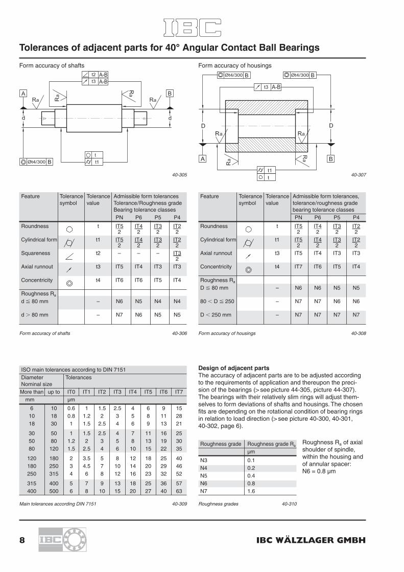
Form accuracy of shafts
40-305 40-307
Form accuracy of housings
Feature Tolerance Tolerance Admissible form tolerancessymbol value Tolerance/Roughness grade
Bearing tolerance classesPN P6 P5 P4
Roundness t IT5 IT4 IT3 IT22 2 2 2
Cylindrical form t1 IT5 IT4 IT3 IT22 2 2 2
Squareness t2 – – – IT32
Axial runnout t3 IT5 IT4 IT3 IT3
Concentricity t4 IT6 IT6 IT5 IT4
Roughness Ra
d � 80 mm – N6 N5 N4 N4
d � 80 mm – N7 N6 N5 N5
Form accuracy of shafts 40-306
ISO main tolerances according to DIN 7151Diameter TolerancesNominal sizeMore than up to IT0 IT1 IT2 IT3 IT4 IT5 IT6 IT7
mm μm
6 10 0.6 1 1.5 2.5 4 6 9 1510 18 0.8 1.2 2 3 5 8 11 2818 30 1 1.5 2.5 4 6 9 13 21
30 50 1 1.5 2.5 4 7 11 16 2550 80 1.2 2 3 5 8 13 19 3080 120 1.5 2.5 4 6 10 15 22 35
120 180 2 3.5 5 8 12 18 25 40180 250 3 4.5 7 10 14 20 29 46250 315 4 6 8 12 16 23 32 52
315 400 5 7 9 13 18 25 36 57400 500 6 8 10 15 20 27 40 63
Main tolerances according DIN 7151 40-309
Roughness Ra of axialshoulder of spindle,within the housing andof annular spacer:N6 = 0.8 μm
Design of adjacent partsThe accuracy of adjacent parts are to be adjusted accordingto the requirements of application and thereupon the preci-sion of the bearings (> see picture 44-305, picture 44-307).The bearings with their relatively slim rings will adjust them-selves to form deviations of shafts and housings. The chosenfits are depending on the rotational condition of bearing ringsin relation to load direction (> see picture 40-300, 40-301, 40-302, page 6).
Feature Tolerance Tolerance Admissible form tolerances,symbol value tolerance/roughness grade
bearing tolerance classesPN P6 P5 P4
Roundness t IT5 IT4 IT3 IT22 2 2 2
Cylindrical form t1 IT5 IT4 IT3 IT22 2 2 2
Axial runnout t3 IT5 IT4 IT3 IT3
Concentricity t4 IT7 IT6 IT5 IT4
Roughness Ra
D � 80 mm – N6 N6 N5 N5
80 � D � 250 – N7 N7 N6 N6
D � 250 mm – N7 N7 N7 N7
Form accuracy of housings 40-308
Roughness grade Roughness grade Ra
μm
N3 0.1N4 0.2N5 0.4N6 0.8N7 1.6
Roughness grades 40-310

IBC INDUSTRIAL BEARINGS AND COMPONENTS 9
Bearing design
Dimensioning of bearingsAccording to DIN ISO 281 the nominal lifetime L10 is resultingout of the ratio between equivalent dynamical stress P todynamical load rating C:(L10 means that 90% of the bearings will attain this lifetime,10% may fail)
L10 = ·106
[h]60 · n [2.0]
Rotational speed n [min-1]Equivalent dynamical bearing stress P [N]
When mounting as single bearing or two single bearings in T-arrangement (tandem):
P = Fr if Fa/Fr < 1.14 [2.1]
P = 0.35 Fr + 0.57 Fa if Fa/Fr > 1.14 [2.2]
Dynamical load capacity C of two single bearings in T-arrangement (tandem) is: Csingle bearing x 1.62.
Determining of axial load accommodated by singlebearings in T-arrangement (tandem)Radial forces are producing an axial component; axial loadhas to be determined according to the already mentioned life-time calculation (> see picture 44-400). (These equations areonly valid under operating conditions without any clearance orpreload.)
The reduction factor R is considering the contactconditions according to load condition Ta/C thatmeans the external axial load and the dynamiccapacity (without external load Ta is R = 1).
Reduction factor R for Ta
44-401
Bearing arrangements in O- or X-arrangement:
P = Fr + 0.55 Fa if Fa/Fr < 1.14 [2.3]
P = 0.57 Fr + 0.93 Fa if Fa/Fr > 1.14 [2.4]
(Fa and Fr affect the bearing pair)
Extended lifetime calculation LnaIn the so called extended lifetime calculation Lna depends on a variety of influences and safety requirements e. g. themodified materials, lubrication conditions, the cleanliness etc.in the modified lubricating gap the lubricant additives and thebearing type.
Lna = a1 a2 a3 L10 [h] [2.5]
a1 life adjustment factora2 factor for material a2 = a2b · a2s · a2w [2.6]a3 factor for operating conditions
Bearing arrangement Load condition Axial force FaA Axial force FaB
case A1
case A2
case A3
case B1
case B2
case B3
X-arrangement
O-arrangement
X-arrangement
O-arrangement
Axial forces with two angular contact ball bearings in X-, O- or in T-arrangement 44-400
�C�3
P
10 IBC WÄLZLAGER GMBH
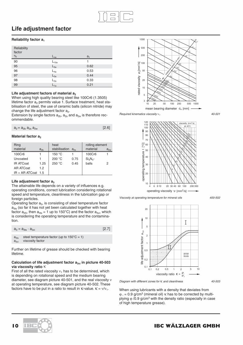
Reliability factor a1
Reliabilityfactor% Lna a1
90 L10a 195 L5a 0.6296 L4a 0.5397 L3a 0.4498 L2a 0.3399 L1a 0.21
Life adjustment factors of material a2When using high quality bearing steel like 100Cr6 (1.3505)lifetime factor a2 permits value 1. Surface treatment, heat sta-bilisation of steel, the use of ceramic balls (silicon nitride) maychange the life adjustment factor a2.Extension by single factors a2b, a2s and a2w is therefore rec-ommendable.
a2 = a2b a2s a2w [2.6]
Material factor a2
Ring heat rolling elementmaterial a2b stabilisation a2s material a2w
100Cr6 1 150 °C 1 100Cr6 1Uncoated 1 200 °C 0.75 Si3N4-IR ATCoat 1.25 250 °C 0.45 balls 2AR ATCoat 1.2IR + AR ATCoat 1.5
Life adjustment factor a3The attainable life depends on a variety of influences e.g.operating conditions, correct lubrication considering rotationalspeed and temperature, cleanliness in the lubrication gap orforeign particles.Operating factor a3, is consisting of steel temperature factora3ts (so far it has not yet been calculated together with heatfactor a2S, then a3ts = 1 up to 150°C) and the factor a3vi, whichis considering the operating temperature and the contamina-tion.
a3 = a3ts · a3vi [2.7]
a3ts steel temperature factor (up to 150°C = 1)a3vi viscosity factor
Further on lifetime of grease should be checked with bearinglifetime.
Calculation of life adjustment factor a3vi in picture 40-503via viscosity ratio κFirst of all the rated viscosity ν1 has to be determined, whichis depending on rotational speed and the medium bearingdiameter, see diagram picture 40-501, and the real viscosity νat operating temperature, see diagram picture 40-502. Thesefactors have to be put in a ratio to result in κ-value. κ = ν/ν1.
Required kinematics viscosity ν1 40-501
Viscosity at operating temperature for mineral oils 400-502
Diagram with different zones for κ and cleanliness 40-503
When using lubricants with a density that deviates from ϕ.. = 0.9 g/cm3 (mineral oil) κ has to be corrected by multi-plying ϕ /0.9 g/cm3 with the density ratio (especially in case of high temperature grease).
Life adjustment factor
rate
d vi
scos
ity
mean bearing diameter
rota
tiona
l spe
ed n
in m
in-1
oper
atin
g te
mpe
ratu
re
operating viscosity
viscosityat
life
adju
stm
ent f
acto
r
viscosity ratio
IBC INDUSTRIAL BEARINGS AND COMPONENTS 11
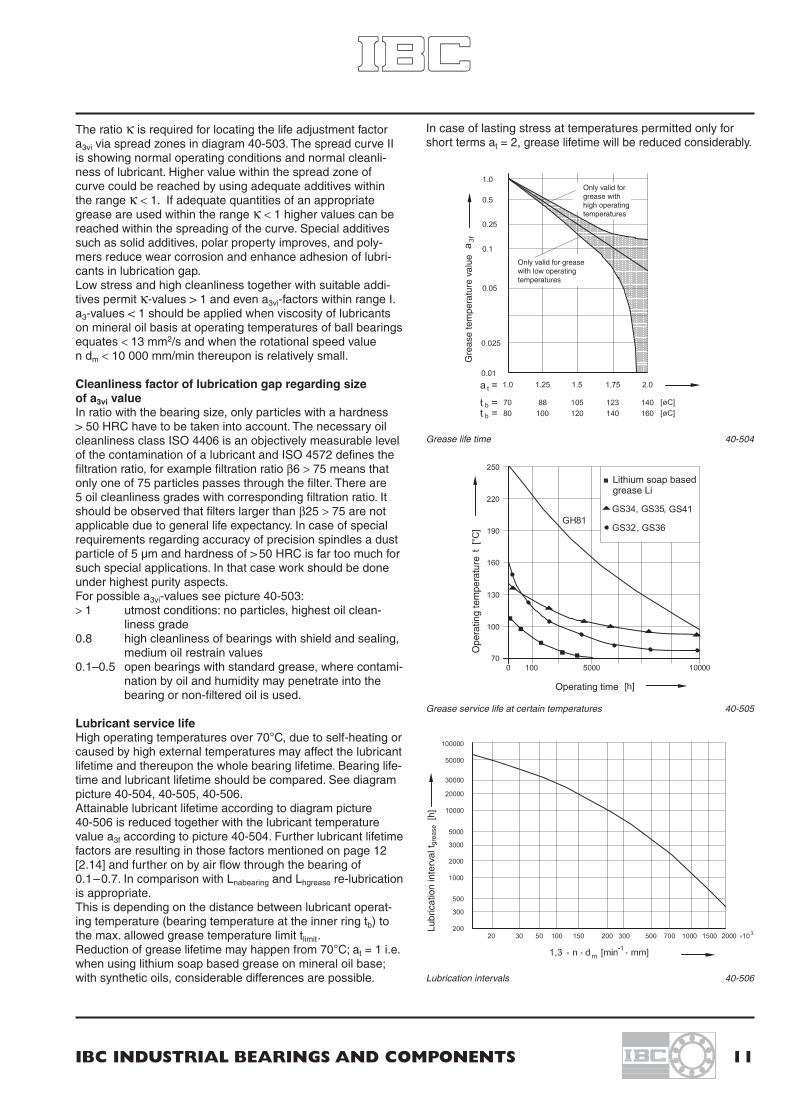
The ratio κ is required for locating the life adjustment factora3vi via spread zones in diagram 40-503. The spread curve IIis showing normal operating conditions and normal cleanli-ness of lubricant. Higher value within the spread zone ofcurve could be reached by using adequate additives withinthe range κ < 1. If adequate quantities of an appropriategrease are used within the range κ < 1 higher values can bereached within the spreading of the curve. Special additivessuch as solid additives, polar property improves, and poly-mers reduce wear corrosion and enhance adhesion of lubri-cants in lubrication gap.Low stress and high cleanliness together with suitable addi-tives permit κ-values > 1 and even a3vi-factors within range I.a3-values < 1 should be applied when viscosity of lubricantson mineral oil basis at operating temperatures of ball bearingsequates < 13 mm2/s and when the rotational speed value n dm < 10 000 mm/min thereupon is relatively small.
Cleanliness factor of lubrication gap regarding size of a3vi valueIn ratio with the bearing size, only particles with a hardness > 50 HRC have to be taken into account. The necessary oilcleanliness class ISO 4406 is an objectively measurable levelof the contamination of a lubricant and ISO 4572 defines thefiltration ratio, for example filtration ratio β6 > 75 means thatonly one of 75 particles passes through the filter. There are 5 oil cleanliness grades with corresponding filtration ratio. Itshould be observed that filters larger than β25 > 75 are notapplicable due to general life expectancy. In case of specialrequirements regarding accuracy of precision spindles a dustparticle of 5 μm and hardness of > 50 HRC is far too much forsuch special applications. In that case work should be doneunder highest purity aspects.For possible a3vi-values see picture 40-503:> 1 utmost conditions: no particles, highest oil clean-
liness grade0.8 high cleanliness of bearings with shield and sealing,
medium oil restrain values0.1–0.5 open bearings with standard grease, where contami-
nation by oil and humidity may penetrate into thebearing or non-filtered oil is used.
Lubricant service lifeHigh operating temperatures over 70°C, due to self-heating orcaused by high external temperatures may affect the lubricantlifetime and thereupon the whole bearing lifetime. Bearing life-time and lubricant lifetime should be compared. See diagrampicture 40-504, 40-505, 40-506.Attainable lubricant lifetime according to diagram picture 40-506 is reduced together with the lubricant temperature value a3f according to picture 40-504. Further lubricant lifetimefactors are resulting in those factors mentioned on page 12[2.14] and further on by air flow through the bearing of0.1–0.7. In comparison with Lnabearing and Lhgrease re-lubricationis appropriate.This is depending on the distance between lubricant operat-ing temperature (bearing temperature at the inner ring tb) tothe max. allowed grease temperature limit tlimit.Reduction of grease lifetime may happen from 70°C; at = 1 i.e.when using lithium soap based grease on mineral oil base;with synthetic oils, considerable differences are possible.
In case of lasting stress at temperatures permitted only forshort terms at = 2, grease lifetime will be reduced considerably.
Grease life time 40-504
Grease service life at certain temperatures 40-505
Lubrication intervals 40-506
Gre
ase
tem
pera
ture
val
ue
limit
Only valid forgrease withhigh operatingtemperatures
Only valid for grease with low operatingtemperatures
Lithium soap based grease Li
Ope
ratin
g te
mpe
ratu
re
Operating time
Lubr
icat
ion
inte
rval
t gre
ase

12 IBC WÄLZLAGER GMBH
Equivalent static bearing load PoFor single bearings and tandem bearings:
Po = 0.5 Fr + 0.26 Fa [2.8]
(Po < Fr calculated with Po = Fr)
For bearing pairs in O- and X-arrangement:
Po = Fr + 0.52 Fa [2.9]
Static load ratings for two matched bearings:
Co = 2 Co single bearing [2.10]
Static safety factor: s0 = C0/P0 [2.11]
The requirements are depending on the requested quiet run-ning and shock load.Usual values for s0: 0.5 ...2
Reference rotational speed nrLoad and lubrication conditions are defined in ISO 15312. Thereference speed for oil and grease are mentioned thereinreferring to a steady state temperature of 70°C.At a constant 5% radial load of static load rating CO, at anambient temperature of 20°C is taken as a basis for oil lubri-cation with mineral oil without EP additives, kinematic viscosi-ty 12 mm2/s (ISO VG 32) with oil level reaching up to 30% ofthe bottom rolling element or grease lubrication with lithiumsoap and mineral base oil of 100–200 mm2/sec (ISO VG 150)at a temperature of 40°C with a filling grade of 30% freespace within the bearing.
When using grease a reference temperature of 70°C can bereached after 20 h of grease distribution.For bearings with rotating outer ring these values may bereduced under certain circumstances. Reference speed val-ues are no speed limits. These figures only state that a tem-perature level of 70°C can be reached for single bearingsunder the above-mentioned load and lubrication conditions.For duplex bearings the rotational speed is reduced by 20%for normal internal bearing clearance. Compared withpolyamide cages the rotational speed for steel and brasscages are reduced by 6%.If no reference speed could be determined such as forsealed bearings, the limiting speed values of rubbing sealsare indicated.Depending on load ratio C/P the following speed characteris-tic values are suitable:
C/P Speed ratio dm x n [mm/min]
15 500 0008 400 0004 300 000
Determination of permissible operating speed npermdepending on load and oil viscosityAs reference speed nr is only defined for a special percentageload ratio under certain lubrication conditions, the admissibleoperational speed nperm for other load and lubrication conditionshas to be determined with the corresponding coefficients.
For reference values for load depending value fp and viscosityfactor fv for oil lubrication please refer to diagram picture 44-507.
nperm = fp fv nr [2.12]
In case of grease lubrication two values are obtained for fvand put into proportion to each other.
nperm = fp fv basic oil actual nr [2.13]
Further reduction factors: [2.14]Vertical shaft: 0.8Rotating outer ring: 0.6Shock load, vibrations: 0.4 ... 0.9
Rotational speed higher than reference speedDue to heat dissipation by oil lubrication, air or liquid coolingof inner and outer rings, higher rotational speed can beobtained.
Correction factors for fp and fv picture 44-507
fv basic oil ISO VG 150

IBC INDUSTRIAL BEARINGS AND COMPONENTS 13
Minimum loadEspecially in case of high-speed bearings a minimum loadshould be designated to avoid sliding of rolling elements.Should the weight of the supported parts not be sufficient,corresponding loads could be applied by spring preloading.For single bearings and tandem arrangements a minimumaxial load Fa min and for bearing arrangements in O- and X-arrangement a minimum radial load Fr min should be applied.
Fa min= ka Co dm
2 n2 10–13 [2.14]
Fr min= kr (n ν) dm
2 10–6 [2.15]
Fa minminimum axial load [N]
Fr minminimum radial load [N]
ka minimum axial load factor for series 72 = 1.4;series 73 = 1.6
kr minimal radial load factor forseries 72 = 95;series 73 = 100
Co static load [N]ν base oil viscosity at operating temperature [mm2/s]n speed [min-1]dm mean bearing diameter [mm]
In case of high speed it has to be taken into considerationthat higher speed means that because of centrifugal forcesthe balls of single spring preloaded bearings at the outerring will be pressed to the centre of the raceway and those atthe inner ring will be pressed up to the bord.To keep the contact angle of 40° of spring preloaded singlebearings constant at the inner and outer ring, the followingminimum spring preload has to be applied:
Fspring = 25 Co2 nmax
2 10–15 [N] [2.16]
open
O-arrangement X-arrangement Tandem-arrangement
Open, sealed 40° angular contact ball bearings as single and matched bearing sets
Designation system 40° Angular Contact Ball Bearings
23
CB 70 05 . BE P . P6 .DBA72 06 . BE K . P5 . UL73 05 . BE P .2RSZ . P5 . UO72 05 . BE J . UA73 07 . BE M . P6 . UA
ACC- 73 08 . BE M . P5 . UO . A15.GH62
Material– Steel balls 100 Cr6CB Ceramic balls Si3N4AC- Rings ATCoatedACC- Rings ATCoated + balls Si3N4
Lubrication– Corrosion protectedG.. BearLub grease
Coating with ATCoat
A11 Inner and outer ring ATCoated A15 Inner and outer ring ATCoated, rolling
elements and cage corrosion protected*A 21 Inner ring ATCoatedA 31 Outer ring ATCoated
Axial clearance/preload, universal bearingUA Axial clearanceUB Small axial clearance UL Light preloadUO Without playA..-.. Axial clearance rangeBearing arrangement DB, DF, DT
Series
70..72..73..
Design CBE 40° contact angle
reinforced inner construction
CageP Window cage PA 6.6 glass fibre reinforcedM Solid machined brassJ Steel sheetK Window cage PEEK glass fibre reinforced
Precision classesP6 Dimensional and running accuracy acc. to ISO class 6P5 Dimensional and running accuracy acc. to ISO class 5P4 Dimensional and running accuracy acc. to ISO class 4
SealingRSZ Friction reduced sealing at one side2RSZ Friction reduced sealing at both sidesARSZ At one side – IR lower bordBRSZ At one side – IR high bord
Designation system 44-900
Bore code
00 10 mm 02 15 mm01 12 mm 03 17 mm
At number 04 and upward x 5 [mm]
44-106*Corrosion protection depending on application, for further
information please refer to main catalogue

14 IBC WÄLZLAGER GMBH
Primary dimensions Basic designation Basic load ratings Fatigue load Reference speed Weightdyn. stat. limit
d D B C Co Pu (radial) nr
mm N N min–1 kg
10 30 9 7200.BE 7 700 3 700 140 30 200 0.030
12 32 10 7201.BE 8 300 4 100 160 28 000 0.03612 37 12 7301.BE 12 900 6 500 210 25 900 0.060
15 35 11 7202.BE 9 600 5 100 205 25 900 0.04515 42 13 7302.BE 16 600 9 600 280 21 600 0.083
17 40 12 7203.BE 11 800 6 500 250 21 600 0.06517 47 14 7303.BE 19 000 10 900 360 19 400 0.110
20 47 14 7204.BE 15 700 8 900 360 18 300 0.11020 52 15 7304.BE 22 200 13 600 430 16 200 0.140
25 47 12 7005.BE 14 800 9 300 385 18 900 0.07425 52 15 7205.BE 17 400 10 900 430 16 200 0.13025 62 17 7305.BE 30 900 19 500 660 14 000 0.230
30 55 13 7006.BE 20 600 13 000 520 15 600 0.11030 62 16 7206.BE 24 200 15 600 660 12 900 0.20030 72 19 7306.BE 37 700 25 200 900 11 800 0.340
35 62 14 7007.BE 27 100 17 500 700 14 200 0.15035 72 17 7207.BE 31 900 21 200 880 11 800 0.28035 80 21 7307.BE 46 000 31 900 1 150 10 800 0.450
40 68 15 7008.BE 32 100 22 000 880 12 400 0.18040 80 18 7208.BE 37 800 26 600 1 100 10 200 0.37040 90 23 7308.BE 57 800 40 500 1 350 9 700 0.630
45 75 16 7009.BE 35 700 24 500 980 11 300 0.23045 85 19 7209.BE 42 000 29 800 1 250 9 700 0.42045 100 25 7309.BE 69 600 50 400 1 750 8 600 0.850
50 80 16 7010.BE 37 000 27 500 1 100 10 200 0.25050 90 20 7210.BE 43 500 33 000 1 350 8 600 0.47050 110 27 7310.BE 81 500 55 500 2 200 7 500 1.100
55 100 21 7211.BE 55 000 41 500 1 650 8 100 0.62055 120 29 7311.BE 91 000 71 000 2 550 7 000 1.400
60 110 22 7212.BE 66 000 51 000 2 150 7 300 0.80060 130 31 7312.BE 104 000 82 500 3 200 6 400 1.750
– Bearings with brass cage M have 5% less capacity due to inner construction.– Static capacity Co of hybride bearings CB = 0.7 Co of bearings with steel balls.

IBC INDUSTRIAL BEARINGS AND COMPONENTS 15
Basic Dimensions Abutment and fillet dimensionsdesignation
a d1 D1 r12minr34min
daminDamax
Dbmaxramax
rbmaxmm mm
7200.BE 13 18.2 23.1 0.6 0.3 15.0 25.0 27.0 0.6 0.3
7201.BE 14 20.2 25.1 0.6 0.3 16.2 27.8 29.0 0.6 0.37301.BE 16 21.8 28.3 1.0 0.6 17.6 31.4 32.8 1.0 0.6
7202.BE 16 22.2 28.0 0.6 0.3 19.2 30.0 32.0 0.6 0.37302.BE 18 26.0 32.6 1.0 0.6 20.6 36.4 37.8 1.0 0.6
7203.BE 18 25.9 31.9 0.6 0.6 21.2 35.0 35.0 0.6 0.37303.BE 20 28.7 36.2 1.0 1.0 22.6 41.4 42.0 1.0 0.6
7204.BE 21 30.7 37.2 1.0 0.6 26.0 41.0 42.4 1.0 0.67304.BE 23 32.9 41.0 1.1 1.0 27.0 45.0 47.8 1.0 0.6
7005.BE 21.5 31.4 40.4 0.6 0.3 30.0 42.0 45.0 0.6 0.37205.BE 24 35.7 42.2 1.0 0.6 31.0 46.0 48.2 1.0 0.67305.BE 27 39.4 48.9 1.1 1.0 32.0 55.0 57.8 1.0 0.6
7006.BE 25 37.2 46.9 0.6 0.3 36.0 49.0 53.0 0.6 0.37206.BE 27 42.3 50.8 1.1 0.6 36.0 56.0 57.4 1.0 0.67306.BE 31 46.2 57.3 1.1 1.0 37.0 65.0 67.8 1.0 0.6
7007.BE 29 43.4 53.3 0.6 0.3 41.0 56.0 60.0 0.6 0.37207.BE 31 49.3 59.0 1.1 0.6 42.0 65.0 67.8 1.0 0.67307.BE 35 52.4 64.2 1.5 1.0 44.0 71.0 74.4 1.5 1.0
7008.BE 32 49.2 58.8 0.6 0.3 46.0 62.0 66.0 0.6 0.37208.BE 34 55.9 66.3 1.1 0.6 47.0 73.0 75.8 1.0 0.67308.BE 39 59.4 72.4 1.5 1.0 49.0 81.0 84.4 1.5 1.0
7009.BE 35 53.2 65.3 0.6 0.3 51.0 69.0 73.0 0.6 0.37209.BE 37 60.5 70.9 1.1 0.6 52.0 78.0 80.8 1.0 0.67309.BE 43 66.3 80.7 1.5 1.0 54.0 91.0 94.4 1.5 1.0
7010.BE 38 57.6 70.3 1.0 0.6 56.0 74.0 78.0 0.6 0.37210.BE 39 65.5 75.9 1.5 1.0 57.0 83.0 85.8 1.0 0.67310.BE 47 73.5 89.7 2.0 1.0 60.0 100.0 104.0 1.5 1.0
7211.BE 43 72.4 84.1 1.5 1.0 64.0 91.0 94.0 1.5 1.07311.BE 51 80.0 97.6 2.0 1.0 65.0 110.0 114.0 2.0 1.0
7212.BE 47 79.3 92.5 1.5 1.0 69.0 101.0 104.0 1.5 1.07312.BE 55 87.0 106.0 2.1 1.1 72.0 118.0 123.0 2.0 1.0

16 IBC WÄLZLAGER GMBH
Primary dimensions Basic designation Basic load ratings Fatigue load Reference speed Weightdyn. stat. limit
d D B C Co Pu (radial) nr
mm N N min–1 kg
65 120 23 7213.BE 74 000 60 500 2 300 6 400 1.00065 140 33 7313.BE 121 000 89 500 3 650 5 900 2.150
70 125 24 7214.BE 80 000 67 500 2 550 5 900 1.10070 150 35 7314.BE 133 500 101 000 3 900 5 400 2.650
75 130 25 7215.BE 82 000 72 000 2 650 5 900 1.20075 160 37 7315.BE 149 000 119 000 4 150 5 400 3.200
80 140 26 7216.BE 92 000 80 000 2 800 5 600 1.40080 170 39 7316.BE 161 000 131 000 4 500 4 800 3.700
85 150 28 7217.BE 103 500 92 000 3 300 5 100 1.80085 180 41 7317.BE 172 500 146 000 4 900 4 800 4.300
90 160 30 7218.BE 122 000 107 000 3 700 4 800 2.20090 190 43 7318.BE 184 000 161 000 5 300 4 300 5.000
95 170 32 7219.BE 133 500 115 000 4 400 4 600 2.600
100 180 34 7220.BE 148 500 131 000 4 400 4 300 3.200100 215 47 7320.BE 222 000 207 000 7 000 3 700 7.200
105 190 36 7221.BE 164 500 148 000 4 800 4 100 4.200
110 200 38 7222.BE 176 000 164 500 4 900 3 700 4.500110 240 50 7322.BE 257 500 257 500 7 200 3 400 9.300
120 215 40 7224.BE 191 000 184 000 5 300 3 400 5.300120 260 55 7324.BE 287 500 299 000 7 700 2 700 12.400
130 230 40 7226.BE 214 000 218 500 6 100 3 200 6.200130 280 58 7326.BE 316 000 345 000 9 000 2 700 15.200
140 250 42 7228.BE 225 500 244 000 6 500 2 700 8.600140 300 62 7328.BE 345 000 391 000 10 000 2 400 20.500
150 270 45 7230.BE 257 500 293 000 7 000 2 400 11.000150 320 65 7330.BE 373 500 448 500 10 500 2 200 25.000
160 290 48 7232.BE 292 000 322 000 8 500 2 300 13.500
170 310 52 7234.BE 334 000 354 000 9 300 2 100 16.000
– Bearings with brass cage M have 5% less capacity due to inner construction.– Static capacity Co of hybrid bearings CB = 0.7 Co of bearings with steel balls.

IBC INDUSTRIAL BEARINGS AND COMPONENTS 17
Basic Dimensions Abutment and fillet dimensionsdesignation
a d1 D1 r12minr34min
daminDamax
Dbmaxramax
rbmaxmm mm
7213.BE 50 86.3 101.0 1.5 1.0 74.0 111.0 114.0 1.5 1.07313.BE 60 93.8 114.0 2.1 1.1 77.0 128.0 133.0 2.0 1.0
7214.BE 53 91.3 106.0 1.5 1.0 79.0 116.0 119.0 1.5 1.07314.BE 64 100.0 123.0 2.1 1.1 82.0 138.0 143.0 2.0 1.0
7215.BE 56 96.5 111.0 1.5 1.0 84.0 121.0 124.0 1.5 1.07315.BE 68 108.0 130.0 2.1 1.1 87.0 148.0 153.0 2.0 1.0
7216.BE 59 104.0 118.0 2.0 1.0 91.0 129.0 134.0 2.0 1.07316.BE 72 115.0 137.0 2.1 1.1 92.0 158.0 163.0 2.0 1.0
7217.BE 63 110.0 127.0 2.0 1.0 96.0 139.0 144.0 2.0 1.07317.BE 76 122.0 145.0 3.0 1.1 99.0 166.0 173.0 2.5 1.0
7218.BE 67 117.0 135.0 2.0 1.0 101.0 149.0 154.0 2.0 1.07318.BE 80 129.0 153.0 3.0 1.1 104.0 176.0 183.0 2.5 1.0
7219.BE 72 124.0 143.0 2.1 1.1 107.0 158.0 163.0 2.0 1.0
7220.BE 76 131.0 151.0 2.1 1.1 112.0 168.0 173.0 2.0 1.07320.BE 90 145.0 173.0 3.0 1.1 114.0 201.0 208.0 2.5 1.0
7221.BE 80 138.0 159.0 2.1 1.1 117.0 178.0 183.0 2.0 1.0
7222.BE 84 145.0 167.0 2.1 1.1 122.0 188.0 193.0 2.0 1.07322.BE 98 161.0 194.0 3.0 1.1 124.0 226.0 233.0 2.5 1.0
7224.BE 90 157.0 179.0 2.1 1.1 132.0 203.0 208.0 2.0 1.07324.BE 107 178.0 211.0 3.0 1.1 134.0 246.0 253.0 2.5 1.0
7226.BE 96 169.0 193.0 3.0 1.1 144.0 216.0 222.0 2.5 1.07326.BE 115 190.0 228.0 4.0 1.5 147.0 263.0 271.0 3.0 1.5
7228.BE 103 183.0 210.0 3.0 1.1 154.0 236.0 243.0 2.5 1.07328.BE 123 203.0 243.0 4.0 1.5 157.0 283.0 291.0 3.0 1.5
7230.BE 111 197.0 226.0 3.0 1.1 164.0 256.0 263.0 2.5 1.07330.BE 131 216.0 259.0 4.0 1.5 167.0 303.0 311.0 3.0 1.5
7232.BE 118 211.0 242.0 3.0 1.1 174.0 276.0 283.0 2.5 1.0
7234.BE 126 226.0 260.0 3.0 1.1 185.0 297.0 304.0 2.5 1.0

18 IBC WÄLZLAGER GMBH
1. Two bearings 7207.BEP.P5.UL with twospacers of same size are used for a cutting knifesupport. Easy mounting is possible without anyfurther adjustments due to ground preload.Grease lubrication rotational speed is 7000 min–1.The whole set has been completely mounted andsupplied by IBC, including shaft and housing.(See picture 44-801, 44-801a)
2. Bearings in O-arrangement have been built inat a belt driven pump support. The O-arrange-ment better bears the moment of tensile load ofthe V-belt. (> See picture 44-802)
(For further components like precision locknuts and labyrinth seals refer to catalogue TI-1-5000.0/E,TI-I-5010.2/E or TI-I-5020.0/E.)
3. In case the pump shaft is driven directly by a motor axially mounted with an intermediatecoupling, X-arrangement should be preferred for better compensation of alignment faults.(> See picture 44-803)
Coupling and motor
More of IBC . . .
Company Profile(German)(English)
LieferprogrammHochgenauigkeits-Wälzlager
Präzisionslagereinheiten · PräzisionsspannmutternTI-I-5000.0 / D
Product RangeSuper Precision BearingsT1-I-5000.0 / D (German)T1-I-5000.0 / E (English)
Product RangePrice List
Super Precision Bearings
TI-I-5003.2 / E
Super Precision BearingsService CatalogT1-1-5003.1 / D (German)T1-1-5003.2 / E (English)
Linear Motion BearingsT1-1-7001.2 / D (German)T1-1-7001.1 / E (English)
IBC Wälzlager mit ATCoatBeschichtungTI-1-5010.2/D
ATCoated BearingsTI-1-5010.2 / D (German)
© Copyright 2006 IBC Wälzlager GmbH
The contents of this publication are the copyright of the publisher and may not be reproduced (even extracts)unless permission is granted. Every care has been taken to ensure the accuracy of the information containedin this publication but no liability can be accepted for any loss or damage whether direct, indirect or conse-quential arising out of the use of the information contained here in.
Wälzlager für KugelgewindetriebeAxial-Schrägkugellager 60°
Präzisionslagereinheiten · PräzisionsspannmutternTI-I-5010.2 / D
Ball Screw Support BearingsTI-I-5010.2 / D (German)TI-I-5010.2 / E (English)
Präzisions-SpannmutternLabyrinth-SpannmutternLabyrinth-Dichtungen
TI-I-5020.0 / D
Precision LocknutsT1-I-5020.0 / D (Deutsch)T1-I-5020.0 / E (English)
Telescopic RailsT1-1-7005.1 / D (German)
IBC WÄLZLAGER GMBHINDUSTRIAL BEARINGS AND COMPONENTS
Post box 1825 · 35528 WETZLAR (GERMANY)
Tel: +49/64 41/95 53-02 Corporate officeFax: +49/64 41/5 30 15 Industriegebiet Oberbiel
D-35606 Solms-Oberbiel
e-mail: [email protected] http://www.ibc-waelzlager.com
IBC INDUSTRIAL BEARINGSAND COMPONENTS AG
Tel: +41/32/6 52 83 53 Corporate officeFax: +41/32/6 52 83 58 Kapellstrasse 26
CH-2540 Grenchen
e-mail: [email protected] http://www.ibc-waelzlager.com