Anesthetic Gas Modulefrankshospitalworkshop.com/...manuals/...Module_-_Service_manual.pdf · • A...
112
Patient Monitoring Service Guide M1026A Anesthetic Gas Module Anesthetic Gas Module M1026A
Transcript of Anesthetic Gas Modulefrankshospitalworkshop.com/...manuals/...Module_-_Service_manual.pdf · • A...

Patient Monitor ing
Service Guide
M1
02
6A
An
est
he
tic
Ga
s M
od
ule
Anesthetic Gas ModuleM1026A

Part Number M1026-9101A
*M1026-9101A*
S PHI
1Table of Contents
Introduction 5Description 5Product Structure 5Physical Specifications 5Environmental Specifications 6Performance Specifications 6
CO2 Measurement 7
AWRR derived from CO2 Waveform 7N2O Measurement 7
O2 Measurement 7
Anesthetic Agent Measurement 7Alarm Ranges 8
Alarm Delay 8
Apnea Alarm 8INOP Alarms 8
General Measurement Principles 9Theory of Operation 9
Main PC Board 10Power Supply 11
Pneumatic System 11
Pump 12Watertrap 12
Sample Flow Through the Pneumatic Path 13
Agent Identification Assembly 13Measurement Principle 14
O2 Sensor 14Specifications 14
Measurement Principle 14
Infrared Measurement Assembly 15Installation and Patient Safety 16
Physical Installation 16Environment 17Label Sheet 17Making Connections to the AGM 17Sample Gas Connections to the Gas Exhaust 18
Returning the Gas Sample 18
Setting Up the Gas Return 19Removing the Gas Sample 20
Setup and Configuration Procedures 20Altitude Configuration 20
3

Connect Sample Input Tubing 20
Preventive Maintenance (PM) Tasks 20Post-Installation Checks 21Safety Requirements Compliance and Considerations 21
Explanation of Symbols Used 21
Power Supply Requirements 22Grounding the System 22
Equipotential Grounding 23
Combining Equipment 23
Checking and Calibrating the Anesthetic Gas Module 23Access Service Functions of the M1026A Anesthetic Gas Module 23When and how to check the Philips M1026A Anesthetic Gas Module 25Equipment required for checking 25Checks and adjustments 26
Performance Leakage Check 26
Performance Diagnostic Check 27
Performance Flowrate Check 27Total Flowrate Check and Adjustment in Purge Mode 27
Measurement Path Flowrate Check and Adjustment 28
Total Flowrate Check in Normal Mode 30
Zero Calibration 30Barometric Pressure Check and Calibration 31Span Calibration Check 32
Disposal of Empty Calibration Gas Cylinder 34
Maintaining the Anesthetic Gas Module 35Preventive Maintenance (PM) Tasks 35Cleaning 36Replace PM Parts 36
Internal Nafion Tubing with Bacterial Filters and manifold Seals 36
Room-Air Filter 38Pump Filter 39Performance Checks 40
Other factors to maximize uptime or reduce cost of ownership: 40
Troubleshooting the Anesthetic Gas Module 40Compatibility Criteria for the AGM and the IntelliVue Monitors 40Flow Charts for Communication and Measurement Type Problems 40Hardware Related Troubleshooting Strategy 45INOPs 46Calibration Checks 48
Calibration Checks Troubleshooting Table 49
Diagnostic Checks 50Problem Solving Hierarchy 51Pneumatic System Diagnostic Checks 52
O2 Assembly Diagnostic Checks 52
Optical Path Disgnostic Checks 55
4

IR Measurement Assembly Diagnostic Checks 56
Agent ID Assmebly Diagnostic Checks 57Power Supply Diagnostic Checks 58
Operating Temperature Diagnostic Checks 59
Test Points, Connectors and Jumpers 59Test Points 59Connectors 60
Jumpers 60
Repairing the Anesthetic Gas Module 62Introduction 62The Top Cover 64
Removal 64
Replacement 64
Lifting the IR Measurement Mounting Bracket 66Removal 67Replacement 67
Infrared Measurement Assembly Head 69Transferring NVRAM Data to a Replacement Head 69
Sample Cell 73Removal 73Replacement 73
Solenoid Valve #1 77Removal 77
Replacement 77
Power Supply Unit 79Removal 79
Replacement 79
Main PC Board 80Removal 80Replacement 81
O2 Sensor 82Removal 82
Replacement 83
Agent Identification Head 85Removal 85
Replacement 86
Pump 87Removal 87Replacement 87
Fan 88Removal 88
Replacement 88
Solenoid Valve #2 90Removal 90
Replacement 90
5

Top Cover PC Board 91Removal 91
Replacement 91
Watertrap Manifold and Protector 93Removal 93
Replacement 93
Power Fuses 94Removal 94Replacement 94
Test and Inspection Matrix 94When to Perform Test Blocks 98Safety Test Appendix 99
Parts List 101Calibration Equipment 106
6

1
1Anesthetic Gas Module
Introduction This chapter contains the following information on the M1026A Anesthesia Gas Module:
• A description of the Module, including its physical, environmental and performance specifications
• A general explanation of the measurement principles that the Module uses to measure gas concentrations
• The theory of operation of the Module: the layout of its components and how they work.
Description The Philips M1026A Anesthetic Gas Module works together with the IntelliVue MP90 patient monitors through an RS232 serial interface. It measures the airway gases of ventilated patients who are under general gas anesthesia, or emerging from it.
The module produces graphical wave data, and inspired and end-tidal numeric data for the following gases:
• CO2
• N2O
• One volatile anesthetic agent
• O2 (optional)
It also generates numerics for the patient’s airway respiration rate (AWRR).
The Agent Identification feature identifies which anesthetic agent is being used.
Product Structure The only version of the M1026A Anesthetic Gas Module compatible with the IntelliVue Monitoring System is:
M1026A #A05: M1026A Watertrap with 5-Agent-ID (Hal, Iso, Enf, Des, Sev)
• #C03 (MUST-Option): adds fast O2 measurement
Physical Specifications Size (H x W x D)
90mm x 370mm x 467mm (3.54 x 14.6 x 18.4 in).
5
1 Anesthetic Gas Module Introduction
Weight
8.2 kg (18 lb).
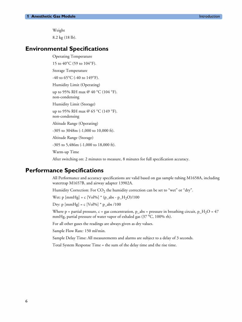
Environmental Specifications Operating Temperature
15 to 40°C (59 to 104°F).
Storage Temperature
-40 to 65°C (-40 to 149°F).
Humidity Limit (Operating)
up to 95% RH max @ 40 °C (104 °F).non-condensing
Humidity Limit (Storage)
up to 95% RH max @ 65 °C (149 °F).non-condensing
Altitude Range (Operating)
-305 to 3048m (-1,000 to 10,000 ft).
Altitude Range (Storage)
-305 to 5,486m (-1,000 to 18,000 ft).
Warm-up Time
After switching on: 2 minutes to measure, 8 minutes for full specification accuracy.
Performance SpecificationsAll Performance and accuracy specifications are valid based on gas sample tubing M1658A, including watertrap M1657B, and airway adapter 13902A.
Humidity Correction: For CO2 the humidity correction can be set to “wet” or “dry”.
Wet: p [mmHg] = c [Vol%] * (p_abs - p_H2O)/100
Dry: p [mmHg] = c [Vol%] * p_abs /100
Where p = partial pressure, c = gas concentration, p_abs = pressure in breathing circuit, p_H2O = 47 mmHg, partial pressure of water vapor of exhaled gas (37 oC, 100% rh).
For all other gases the readings are always given as dry values.
Sample Flow Rate: 150 ml/min.
Sample Delay Time: All measurements and alarms are subject to a delay of 3 seconds.
Total System Response Time = the sum of the delay time and the rise time.
6

Introduction 1 Anesthetic Gas Module
CO2 Measurement
The total system response time is the sum of the sample delay time (3 seconds) and the rise time (410 msec typical)
AWRR derived from CO2 Waveform
N2O Measurement
O2 Measurement
Anesthetic Agent Measurement
Range: 0 to 76 mmHg
Accuracy: 1.5 mmHg (0 - 40 mmHg)2.5 mmHg (40 - 60 mmHg)4.0 mmHg (60 - 76 mmHg)
Resolution: 1 mmHg
Rise-time: 410 msec typical
Range: 0 to 60 rpm
Accuracy: ± 2 rpm
Resolution: 1 rpm
Detection Criteria: 6 mmHg variation in CO2
Range: 0 to 85 vol%
Accuracy: 1.5 vol% + 5% relative
Resolution: 1 vol%
Rise-time: 510 msec typical
Range: 0 to 100vol%
Accuracy: ± 2.5 vol% or 5% relative, whichever is the greater.
Resolution: 1 vol%
Rise-time: 450 msec typical
Agent Range (vol%) Accuracy Resolution Rise Time
Halothane 0 - 7.5 0.2 vol% + 4.0% relative 0.05 < 740
Enflurane 0 - 7.5 0.1 vol% + 4.0% relative 0.05 < 620
7
1 Anesthetic Gas Module Introduction
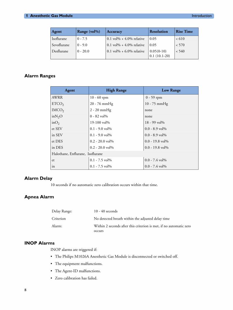
Alarm Ranges
Alarm Delay10 seconds if no automatic zero calibration occurs within that time.
Apnea Alarm
INOP AlarmsINOP alarms are triggered if:
• The Philips M1026A Anesthetic Gas Module is disconnected or switched off.
• The equipment malfunctions.
• The Agent-ID malfunctions.
• Zero calibration has failed.
Isoflurane 0 - 7.5 0.1 vol% + 4.0% relative 0.05 < 610
Sevoflurane 0 - 9.0 0.1 vol% + 4.0% relative 0.05 < 570
Desflurane 0 - 20.0 0.1 vol% + 6.0% relative 0.05 (0-10) 0.1 (10.1-20)
< 540
Agent Range (vol%) Accuracy Resolution Rise Time
Agent High Range Low Range
AWRR 10 - 60 rpm 0 - 59 rpm
ETCO2 20 - 76 mmHg 10 - 75 mmHg
IMCO2 2 - 20 mmHg none
inN2O 0 - 82 vol% none
inO2 19-100 vol% 18 - 99 vol%
et SEV 0.1 - 9.0 vol% 0.0 - 8.9 vol%
in SEV 0.1 - 9.0 vol% 0.0 - 8.9 vol%
et DES 0.2 - 20.0 vol% 0.0 - 19.8 vol%
in DES 0.2 - 20.0 vol% 0.0 - 19.8 vol%
Halothane, Enflurane, Isoflurane
et 0.1 - 7.5 vol% 0.0 - 7.4 vol%
in 0.1 - 7.5 vol% 0.0 - 7.4 vol%
Delay Range: 10 - 40 seconds
Criterion No detected breath within the adjusted delay time
Alarm: Within 2 seconds after this criterion is met, if no automatic zero occurs
8

Introduction 1 Anesthetic Gas Module
• Zero calibration is in progress.
• The gas sample tube is occluded, or the water trap is full.
• The Philips M1026A Anesthetic Gas Module is unable to measure.
• Gas contaminant is detected.
• Agent mixture detected.
• Anesthetic agent detected but not selected.
• The module is in warm-up mode.
• No breath detected.
• The Anesthetic Gas Module is incompatible with the monitor
General Measurement Principles The Philips M1026A Anesthetic Gas Module uses a technique called Non-Dispersive Infrared Gas Concentration Measurement (NDIR) to measure the concentration of gases.
This works as follows:
• The gases that the Philips M1026A Anesthetic Gas Module can measure absorb infrared (IR) light.
• Each gas has its own absorption characteristic. The gas mixture is transported into a sample cell, and an IR filter selects a specific band of IR light to pass through the gas. For multiple gas measurements, multiple IR filters are used.
• The higher the concentration of gas in the mixture the more IR light it absorbs. This means that higher concentrations of IR absorbing gas results in lower transmission of IR light.
• The amount of IR light transmitted through an IR absorbing gas is measured.
• From the amount of IR light transmitted, the concentration of gas can be calculated. This calculation provides the gas concentration value.
O2 gas cannot be measured with this technique as it does not absorb IR light. Hence O2 gas is measured with a sensor that makes use of the paramagnetic properties of O2 for its fast measurement technique.
Theory of Operation Figure 1 shows the functional blocks within the Philips M1026A Anesthetic Gas Module.
9

1 Anesthetic Gas Module Introduction
Figure 1 Anesthetic Gas Module Functional Block Diagram
The main components of the Philips M1026A Anesthetic Gas Module are:
• Main PC Board.
• Switching Power Supply.
• Pneumatic System.
• Agent Identification.
• O2 Sensor.
• Infrared Measurement Assembly.
Main PC Board This digital board:
• Controls the pneumatic system and the IR measurement assembly.
• Converts the preamplified analog output signal from the IR detector into a digital value. Under software-controlled processing, this is then converted to a fully compensated gas concentration value.
• Converts analog signals from the sample cell pressure sensor, transducer, sample cell temperature thermistor, and the ambient temperature thermistor, into digital environmental data for gas compensation and data reporting.
• Converts an analog O2 signal, supplied by the O2 measurement system, into O2 concentration data for CO2 compensation and O2 data reporting.
10

Introduction 1 Anesthetic Gas Module
• Converts analog signals from the flow-control servo system and power supply into digital data for status reporting.
• Processes the algorithm for end-tidal, inspired and respiration rate values.
• Controls the communication between the monitor and the Philips M1026A Anesthetic Gas Module through an RS232 interface that uses a standard communications protocol.
• Contains the software program that controls the Philips M1026A Anesthetic Gas Module in a 128K EPROM.
Power Supply The input voltage is 100V - 240V. The output voltages are ±12V and +5V and the maximum output is 55W.
Pneumatic SystemThe main parts of the pneumatic system are:
• Watertrap.
• Pump assembly, including pump outlet filter.
• Two solenoid valves.
• Tubing system including:
– Differential pressure transducer and restrictor for control of the total flow.
– Measurement path.
– Drainage path parallel to measurement path.
• Ambient air reference filter.
Figure 2 Pneumatic System
11

1 Anesthetic Gas Module Introduction
The pneumatic system works in the following way:
1 Eliminates residual water and fluids from patient sample gas using the watertrap and eliminates water vapor using Nafion Tubing.
2 Splits the patient’s sample gas flow (150ml/min) into the measurement path (120ml/min) and drainage path (30ml/min).
3 Passes the patient’s sample gas in the measurement path at 120ml/min through the measurement benches.
4 Delivers zero calibration gas to the sample cells for the periodic zeroing.
5 Exhausts the patient’s sample gas, the zero calibration gas, and the span calibration gas.
6 Monitors for an occlusion in the sampling pneumatics.
PumpThe servo-controlled pump is attached to the exhaust of the Anesthetic Gas Module. It generates the flow through the system and pulls the gas from the airway adapter through the measurement subsystems to the exhaust outlet. It also delivers the zero calibration gas to the sample cells of the measurement subsystems for the periodic zero procedures and it exhausts the patient’s sample gas, the zero calibration and field calibration gases.
The flow-rate control logic drives the pump as hard as necessary to maintain the selected flow rate. A partial occlusion or an inefficient pump results in the pump being driven harder. A serious occlusion results in the pump being driven at or near its maximum load. This triggers a sensing circuit, which then reports an occlusion.
Watertrap
Figure 3 Watertrap
Patient Sample Inlet
Water Reservoir
Water Fuses
Water Separation Filters
12

Introduction 1 Anesthetic Gas Module
The watertrap consists of two water separation filters, two water fuses and a water reservoir. The gas sample coming from the patient may contain fluids which are separated from the gas at the first water separation filter. The gas is then split into two paths, the “measurement” path with the main part of the total gas flow (including water vapor) continuing on the “dry” side of the separation filter and the “drainage” path (containing any liquid droplets) with the smaller amount of the total flow continuing on the “wet” side of this filter. At the pump both gas paths are recombined.
The watertrap proper includes “water fuses” in both the “measurement” and the “drainage” paths, consisting of a material that swells when getting wet (when the reservoir is full or when fluid penetrates the separation filter and enters the “measurement” path) and blocks the respective path at the inlet of the unit. Once the “water fuses” are blown, any passage of fluid is blocked and the gas flow resistance increases so that an occlusion is detected.
Sample Flow Through the Pneumatic Path• The drainage path serves to withdraw fluid separated from the gas sample into the watertrap
reservoir, so that the AGM interior is protected from fluid that might cause an occlusion in the measurement path.The drainage path leads into the large watertrap reservoir where all liquid water and other fluids are collected. When the drainage path leaves the watertrap through a water separation filter and a through a water fuse it leads through internal Nafion tubing then through a bacterial protection filter and flow restrictor directly to the pump. This flow restrictor determines the percentage distribution between drainage and measurement path flow.
• The measurement path leads through a water separation filter and through a water fuse on into the measurement system. The patient sample gas (on the measurement path) then flows through internal Nafion tubing and through a bacterial protection filter to the first solenoid valve. Room air for the zero calibration is alternatively input (via a dust filter) to this solenoid valve. The solenoid valve switches between the two gases depending on the current mode of operation - normal measurement or zero calibration.
The patient sample gas or zero calibration gas then flows through the measurement subassemblies:
• the IR Measurement Assembly (for measurement of anesthetic agent, CO2 and N2O)
• the O2 cell (if present)
• the Agent Identification assembly.
A second solenoid valve between the O2 cell and the Agent Identification Assembly routes room air directly to the Agent Identification Assembly for optimal purging of the assembly during zero calibration.
From the Agent Identification Assembly the patient sample gas or zero calibration gas flows to the pump. Before reaching the pump, it joins the drainage path again.
From here it is passed through a filter and damper to the flow sensor which consists of a differential pressure transducer and a flow restrictor. The flow sensor determines, stabilizes and limits the flow rate of the sampled gas.
After the gas has passed through the flow sensor it is routed through a second damper to the Sample Gas output.
Agent Identification AssemblyThe agent ID analyzer identifies which anesthetic agents are present in a gas sample drawn from the patients’s airway. The anesthetic agents are identified from a set of known anesthetic gases.
13

1 Anesthetic Gas Module Introduction
Measurement PrincipleSample gas passes through the agent identification head where the absorption characteristics of the gas are measured. This is done using NDIR technology as described in General Measurement Principles. The head outputs analog signals and sends them for processing to identify the anesthetic agent.
Data averaging is used to ensure accurate measurements when agent concentrations are low. The information used to calculate the concentrations of the three agents includes:
• The preamplified outputs from the IR detector.
• The thermistor output from the agent identification head.
• Zero calibration constants.
O2 Sensor
Specifications
Measurement Principle The O2 sensor uses a fast O2 measurement technique that utilizes O2 paramagnetic properties.
Two sealed spheres forming a dumb-bell assembly are filled with N2. The dumb-bell assembly is suspended in a symmetrical non-uniform magnetic field. The spheres take up a position away from the most intense part of the field, due to the diamagnetic force on the dumbbells. The dumb-bell assembly is then surrounded by the sample gas.
When the surrounding sample gas contains O2, the dumb-bell spheres are forced even further out of the magnetic field by the relatively stronger paramagnetic O2 gas. The torque acting on the dumb-bell is proportional to the paramagnetism of the surrounding gases, and can therefore be taken as a measure of the oxygen concentration.
This torque is measured by monitoring the current required in a servo system that attempts to return the dumb-bells to their normal position.
Isoflurane
Enflurane
Halothane
Sevoflurane
Desflurane
Weight 335 g (0.75 lbs)
Size (HxWxD) 54 x 54 x 56 mm
Calibration Zero: Room AirSpan: Suitable calibrated mixture
14

Introduction 1 Anesthetic Gas Module
Infrared Measurement Assembly The measurement assembly measures the IR light absorption of the gases in its sample cell (see Figure 4).
Figure 4 Anesthetic Gas Module Measurement Assembly
The measurement assembly contains the following subassemblies:
IR Source: The ceramic IR source is heated to 600°C by applying a constant drive voltage across it.
Filter Wheel Assembly: The filter wheel assembly includes IR filters for the anesthetic agent, CO2, N2O and a reference channel. A blank segment (dark period) marks the beginning and end of the filter series.
Sample Cell: The sample cell is a stainless steel tube. It has non-IR absorbing sapphire windows at both ends, and barbed inlet and outlet ports. The inlet and outlet ports are placed as close as possible to the windows so that the gas flows effectively through the cell.
Preamp Assembly The preamplifier board assembly includes an IR detector, an IR-detector thermistor, a TE cooler, and a pre-amplification circuit. The output from the preamplifier is a stream of pulses; this pulse train has one pulse for each IR filter, and is terminated by a blank period (dark level phase) (see Figure 5).
15

1 Anesthetic Gas Module Installation and Patient Safety
Figure 5 IR Detector Output Signal
Installation and Patient SafetyThis chapter describes how to install the Philips M1026A Anesthetic Gas Module. It details the operating environment required by the Philips M1026A Anesthetic Gas Module as well as instructions on how to affix the local language labels and physically connect it to the monitor. Next, the patient safety information is detailed. Finally, this chapter describes the software setup required and any post-installation checks that have to be performed before using the Philips M1026A Anesthetic Gas Module together with a reminder of the preventive maintenance (PM) checks and their frequencies.
Where post-installation procedures are specific to installation, they are described in full in this chapter. For procedures which are also used in other situations (for example calibration, preventative maintenance, etc.), a reference to the description will be given.
Physical InstallationThis section describes the operating and storage environment for the Philips M1026A Anesthetic Gas Module, affixing the local-language labels, connecting to the monitor, and fitting the gas exhaust return system.
CAUTION The Philips M1026A Anesthetic Gas Module must be positioned horizontally on a level surface. To avoid condensed water collecting in the patient sample tube, it is recommended that the Philips M1026A Anesthetic Gas Module is positioned at or above patient level, wherever possible.
16

Installation and Patient Safety 1 Anesthetic Gas Module
Environment
WARNING Possible explosion hazard if used in the presence of flammable anesthetics.
The environment where the Philips M1026A Anesthetic Gas Module is used should be free from vibration, dust, corrosive or explosive gases, and extremes of temperature and humidity.
For a cabinet mounted installation with the monitor, allow sufficient room at the front for operation and sufficient room at the rear for servicing with the cabinet access door open.
The Philips M1026A Anesthetic Gas Module operates within specifications at ambient temperatures between 15°C and 40°C, 8 minutes after switching it on.
Ambient temperatures that exceed these limits could affect the accuracy of this instrument and cause damage to the components and circuits. Allow at least 2 inches (5cm) clearance around the instruments for proper air circulation.
CAUTION If the Philips M1026A Anesthetic Gas Module has been stored at temperatures below freezing, it needs a minimum of 4 hours at room temperature to warm up before any connections are made to it.
Make sure that the Philips M1026A Anesthetic Gas Module is free of condensation before operation. Condensation can form when equipment is moved from one building to another, thus being exposed to moisture and differences in temperature.
Label SheetThere is a label sheet included with the Philips M1026A Anesthetic Gas Module which has the translated versions for “Airway Gases”. You can stick a translated version over “Airway Gases” on the left of the front panel. See (1) in Figure 6.
Figure 6 Label for the Philips M1026A Anesthetic Gas Module
Making Connections to the AGMAll connections to the AGM are made on its rear panel. Refer to Figure 7.
PAD M1026A
17

1 Anesthetic Gas Module Installation and Patient Safety
Figure 7 The Rear Panel
1 Local power connector; this is a 3-pin connector, used to connect the AGM to the local line voltage supply.
The module can be operated from an ac power source of 100 - 240 V ± 10%, 50/60 Hz. The adjustment is made automatically by the power supply inside the module.
2 RS232 Connector (RS232 Interface); this is a 25-pin “D” type connector, used to connect the AGM to the RJ45 connector of the monitor (Slot 08a, 07a, 04a, 03a, or 02a, - MIB I/O port - see Connection of Devices via the MIB/RS232 Interface in the Installation Instructions section).
The connection can be made with the following cables:
– M1026A#K11 1 m (M1026-61001)
– M1026A#K12 3 m (M1026-61002)
– M1026A#K13 10 m (M1026-61003)
3 Equipotential Grounding Terminal; this is used to connect the AGM to the hospital’s grounding system.
4 Line protection fuses, T1.6 H 250V.
5 Anesthetic gas exhaust. If N2O and/or other inhalation anesthetics are used during anesthesia, pollution of the operating room should be prevented. Once the gas sample has passed through the AGM, it should either be returned to or removed from the anesthesia circuit.
Sample Gas Connections to the Gas Exhaust
Returning the Gas Sample You will need the following equipment to return the gas sample to the anesthesia circuit:
RS 232
MONITOR
100-240V
T1.6 H 250V
600VA max.
GasOutlet
(6)RS232
Connector
(2)Fuses
(5)LocalPower
Connector
EquipotentialGroundingTerminal
(4)(1)
brear2d.tif
60/140
50-60 Hz
18
Installation and Patient Safety 1 Anesthetic Gas Module
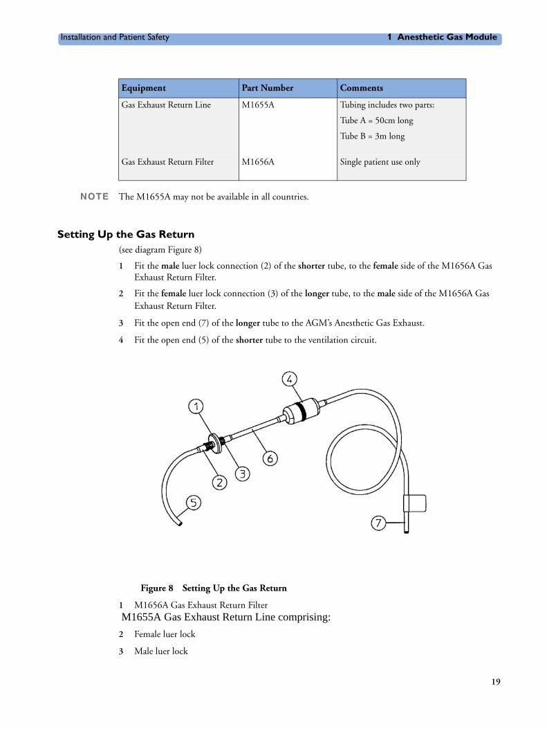
NOTE The M1655A may not be available in all countries.
Setting Up the Gas Return (see diagram Figure 8)
1 Fit the male luer lock connection (2) of the shorter tube, to the female side of the M1656A Gas Exhaust Return Filter.
2 Fit the female luer lock connection (3) of the longer tube, to the male side of the M1656A Gas Exhaust Return Filter.
3 Fit the open end (7) of the longer tube to the AGM’s Anesthetic Gas Exhaust.
4 Fit the open end (5) of the shorter tube to the ventilation circuit.
Figure 8 Setting Up the Gas Return
1 M1656A Gas Exhaust Return Filter M1655A Gas Exhaust Return Line comprising:
2 Female luer lock
3 Male luer lock
Equipment Part Number Comments
Gas Exhaust Return Line M1655A Tubing includes two parts:
Tube A = 50cm long
Tube B = 3m long
Gas Exhaust Return Filter M1656A Single patient use only
19

1 Anesthetic Gas Module Installation and Patient Safety
4 Dampener
5 Shorter tube
6 Connecting tube
7 Longer tube - connected to AGM exhaust port
Removing the Gas Sample To remove the gas sample from the anesthesia circuit, a scavenging system needs to be connected to the AGM’s Anesthetic Gas Exhaust. If you intend to use a scavenging system with the AGM, one of the following parts must also be connected to protect it against malfunction:
1 A ventilator reservoir where the suction pressure does not exceed 0.3-0.4 mmHg or
2 A scavenging interface, properly set and maintained (see scavenging interface manufacturer’s instructions).
Setup and Configuration Procedures
This section describes final setting up and configuration procedures that must be completed after the AGM is connected to the monitor and switched on but before the AGM is used for monitoring.
Altitude ConfigurationThe altitude setting for the monitor is important as it is used as a reference to check the AGM ambient pressure measurement.
See the Installation Instructions section for details.
Connect Sample Input TubingConnect the sample input tubing to the watertrap at the patient sample inlet on the water separation filter. For details, refer to the Instructions for Use.
Preventive Maintenance (PM) TasksThe preventive maintenance (PM) tasks are described in detail in chapter 5 of this guide. Here is a short list of the PM tasks and how often they must be performed.
To ensure operation of the Philips M1026A Anesthetic Gas Module within specified limits:
1 Check the ventilator fan in the AGM for proper operation and build-up of dust and lint every 6 months.
2 Check the AGM’s calibration at least once every 12 months, or whenever the validity of the readings is in doubt.
3 Replace the internal Nafion; tubing, room air filter, and pump filter, internal bacterial filters and watertrap manifold seals, using the PM kit, every 12 months.
4 Test the pump using the test procedure provided in the PM Kit every 12 months. The square-shaped pump should be cleaned before testing; the round-shaped pump may not be cleaned.
5 Check electrical safety (ground impedance test and enclosure leakage current test) at least every 12 months.
All safety and maintenance checks must be made by qualified service personnel.
20

Installation and Patient Safety 1 Anesthetic Gas Module
WARNING Failure to implement a satisfactory maintenance schedule by the individual, hospital or institution responsible for the operation of this equipment may cause equipment failure and possible health hazards.
Post-Installation Checks See Test and Inspection Matrix for details.
WARNING Do not use the instrument for any monitoring procedure on a patient if you identify anything which indicates impaired functioning of the instrument.
Safety Requirements Compliance and ConsiderationsThe Philips M1026A Anesthetic Gas Module complies with the following international safety requirements for medical electrical equipment:
• UL 2601-1
• IEC-60601-1
• CSA C22.2 No. 601.1-M90
• EN 60601-1
• EN 60601-1-2
Explanation of Symbols Used
Attention, consult accompanying documents.
Indicates that the instrument is type CF and is designed to have special protection against electric shocks (particularly regarding allowable leakage currents, having an F-Type isolated (Floating) applied part), and is defibrillator proof.
A gas output (this symbol is also used to indicate an electrical output on the monitor).
21

1 Anesthetic Gas Module Installation and Patient Safety
The Anesthetic Gas Module is protected against the effects of defibrillation and electrosurgery.
Power Supply RequirementsThe system and the Anesthetic Gas Module can both be operated from an AC supply of 100 - 240V ±10%, 50 - 60Hz.
Grounding the SystemTo protect the patient and hospital personnel, the cabinet of the installed equipment has to be grounded. The equipment is supplied with a detachable 3-wire cable which grounds the instrument to the power line ground (protective earth) when plugged into an appropriate 3-wire receptacle. If a 3-wire receptacle is not available, consult the hospital electrician.
A gas input (on the monitor this symbol can also stand for a video or 60V dc input).
Equipotential grounding terminal.
RS232 communication port.
Fuse.
Protective earth ground.
Electrical shock hazard.
22
Checking and Calibrating the Anesthetic Gas Module 1 Anesthetic Gas Module
WARNING Do not use a 3-wire to 2-wire adapter.
Equipotential GroundingProtection class 1 instruments are already included in the protective grounding (protective earth) system of the room by way of grounding contacts in the power plug. For internal examinations on the heart or the brain, Computer Module and Display Module of the System and the Philips M1026A Anesthetic Gas Module must have separate connections to the equipotential grounding system.
One end of the equipotential grounding cable (potential equalization conductor) is connected to the equipotential grounding terminal on the instrument’s rear panel and the other end to one point of the equipotential grounding system. The equipotential grounding system assumes the safety function of the protective grounding conductor if ever there is a break in the protective grounding system.
Examinations in or on the heart (or brain) should only be carried out in rooms designed for medical use incorporating an equipotential grounding system.
Combining EquipmentIf it is not evident from the instrument specifications whether a particular instrument combination is hazardous or not, for example, due to summation of leakage currents, the user should consult the manufacturers concerned or an expert in the field, to ensure that the necessary safety of all instruments concerned will not be impaired by the proposed combination.
Checking and Calibrating the Anesthetic Gas Module
This chapter explains how to check the Anesthetic Gas Module to ensure that it is operating within its specified limits. A list of the equipment required to carry out the checks is included, as well as step-by step instructions for the calibrations.
If you receive fail indications while testing, refer to the troubleshooting section of this chapter for guidance. If you are instructed to remove or replace parts of the Anesthetic Gas Module refer to the respective section.
Access Service Functions of the M1026A Anesthetic Gas ModuleEnter service mode and select the service screen (see Testing and Maintenance for instructions on entering service mode). In the Setup Gas Analyzer menu you can choose whether the Gas Analyzer Diagnostic window or the Gas Analyzer Calibration window should be displayed. In this window you can as well start the flow calibration, the barometric pressure calibration and the gas span calibration.
The Setup Gas Analyzer menu can be accessed by either going to the Main Setup menu and selecting Gas Analyzer, or by pressing the setup key on the Anesthetic Gas Module.
23
1 Anesthetic Gas Module Checking and Calibrating the Anesthetic Gas Module
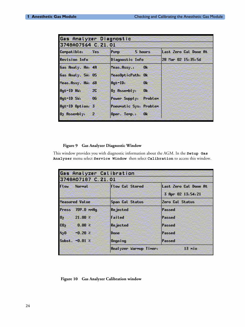
Figure 9 Gas Analyzer Diagnostic Window
This window provides you with diagnostic information about the AGM. In the Setup Gas Analyzer menu select Service Window then select Calibration to access this window.
Figure 10 Gas Analyzer Calibration window
24

Checking and Calibrating the Anesthetic Gas Module 1 Anesthetic Gas Module
This window provides you with information about all calibrations that can be performed on the Anesthetic Gas Module. In the Setup Gas Analyzer menu select Service Window then select Diagnostic to access this window.
When and how to check the Philips M1026A Anesthetic Gas ModuleTo ensure that the Philips M1026A Anesthetic Gas Module operates with the specified limits, it must be checked:
1 After installation
2 Every 12 months or if the measurements are in doubt.
3 After repairing the AGM
If you find values outside the tolerance limits while checking, the Philips M1026A Anesthetic Gas Module must be recalibrated. Tolerance values are given at the end of each section.
The basic steps to check the Philips M1026A Anesthetic Gas Module are:
1 Enter Service Mode at the monitor and wait for first automatic zero calibration after the warm-up period.
2 Perform:
a. a leakage check
b. a flowrate check
to ensure that there are no leaks in the gas system and that the flowrates are set correctly.
3 Perform Zero calibration.
4 Check that there are no reported errors.
5 Check the Barometric Pressure calibration; perform it if necessary.
6 Check the Span calibration of gases; perform it if necessary.
7 If Barometric Pressure or Span calibrations were performed, re-perform Zero calibration.
WARNING Only perform Zero, Barometric Pressure and gas Span calibration checks when the top cover is closed. Light and electro-magnetic interference can affect the measurements.
Equipment required for checkingThe following equipment is required for checking the AGM. Part numbers are given in the Parts List section.
1 Electronic Flowmeter M1026-60144 (Instructions are provided with the flowmeter. See also Service Note M1026A-034).
2 Span Calibration Equipment.
– Calibration Gas.
– Calibration Tubing
25

1 Anesthetic Gas Module Checking and Calibrating the Anesthetic Gas Module
WARNING Philips Calibration Gas contains Halocarbon 22. Halocarbon 22 is represented in the Calibration menu by “Substitute”, which is the default. If you are using another calibration gas, this must be selected in the menu.
Checks and adjustmentsThe following sections explain the steps needed to carry out the checks and adjustments. A complete check and calibration procedure requires approximately 45 minutes, including waiting time.
NOTE Make sure that the watertrap is attached.
Performance Leakage CheckComplete the following steps to do a performance leakage check:
NOTE Do not perform the leakage check while a Zero calibration is running.
1 Switch on the Philips M1026A Anesthetic Gas Module and the monitor.
2 Wait until the Anesthetic Gas Module enters the warm up phase.
3 Connect a flowmeter to the exhaust outlet of the Philips M1026A Anesthetic Gas Module.
4 Connect the watertrap to the watertrap manifold.
5 Note the flowrate.
6 Block the gas inlet at the watertrap inlet connector (use your fingertip).
The reading at the flowmeter should decrease to Zero (see table below). If it does not, systematically block the pneumatic path at various points before the pump to isolate the leakage point. (See Figure 2, "Pneumatic System" for tubing connections.) When the fault has been corrected, repeat the leakage check.
7 Connect the flowmeter to the inlet.
8 Note the flowrate.
9 Block the Anesthetic Gas Module exhaust (using your finger tip).
10 Check the effect of blocking the exhaust.
The reading at the flowmeter should decrease to Zero (see Table 4-1). If it does not, systematically block the pneumatic path at various points after the pump to isolate the leakage point. (See Figure 2, "Pneumatic System" for tubing connections.) When the fault has been corrected, repeat the leakage check.
Items Value / Tolerance
Leakage Range: 0 → 4 ml/min
26

Checking and Calibrating the Anesthetic Gas Module 1 Anesthetic Gas Module
Performance Diagnostic CheckComplete the following to do a performance diagnostic check:
1 Enter the service mode of the monitor and let the Philips M1026A Anesthetic Gas Module complete the warm-up phase (the GA WARMUP INOP disapears).
2 Make sure that the watertrap is attached.
3 In the Setup Gas Analyzer menu select Service Window then select Diagnostic to access the Gas Analyzer Diagnostic window.
4 Check that no permanent problems are reported for the Philips M1026A Anesthetic Gas Module in the Gas Analyzer Diagnostic window.
Performance Flowrate CheckAlways perform a leakage check before the flowrate check. Three flowrates need to be checked in the following order:
1 Total flow in Purge mode.
2 Flow in Measurement Path in Normal mode.
3 Total flow in Normal mode.
These flowrate checks are described in the following three procedures.
The total flow is measured by connecting the flowmeter to the exhaust, the measurement path flow is measured by connecting the flowmeter to the gas inlet with a special test fixture.
The Flowrate values are summarized in the following table:
NOTE Do not perform the flowrate check while a Zero calibration is running.
Total Flowrate Check and Adjustment in Purge ModeTo make the flowrate measurements and any necessary adjustment:
1 Enter the service mode of the monitor and let the Philips M1026A Anesthetic Gas Module complete the warm-up phase (the GA WARMUP INOP disapears).
2 In the Setup Gas Analyzer menu select Service Window then select Calibration to access the Gas Analyzer Calibration window.
3 Enter the Setup Gas Analyzer menu and select Start Flow Cal.
4 Select Flow Rate.
5 Select Purge for purge flow (310 ml/min).
6 Connect a flowmeter to the exhaust port of the Philips M1026A Anesthetic Gas Module.
Total Flowrate Value
Purge 310 ml/min
Normal 150 ml/min
27
1 Anesthetic Gas Module Checking and Calibrating the Anesthetic Gas Module
7 Note the actual flowrate by following the instructions accompanying the flowmeter. If the actual flowrate is outside the tolerance, it must be adjusted. If no adjustments are required, select Stop Flow Cal.
Flowrate Adjustment:
8 Remove the Philips M1026A Anesthetic Gas Module top cover (see “The Top Cover” on page 64)
9 Correct the flowrate by adjusting potentiometer R125 on the Main PC board until the required value is achieved.
Flowrate Calibration:
10 If you have made adjustments you must save the settings. Therefore select Store Flow Cal and confirm when prompted.The system then runs through various flowrates and switches the pump off before it saves the values internally.The flow display in the Calibration window reflects these changes and the status “Flow Cal Stored” appears.
11 Disconnect the flowmeter from the exhaust port.
Measurement Path Flowrate Check and AdjustmentThe flowrate of the measurement path is checked using a test fixture in the form of a modified watertrap. In order to perform the flow rate check, the following equipment is required:
• Flow Split Test Tool M1026-60136
• Electronic Flowmeter M1026-60144
NOTE 1 Check that the test fixture is still valid for use. It must be less than two years old. The test fixture is labelled with a “Received” date that needs to be filled in when the test fixture is received.
2 The flow value that is labelled on the test fixture is to be used to perform the measurement path flowrate check. It is only valid for this test fixture.
3 Check the test fixture visually for leaks. Regularly perform a leakage check with the test fixture attached instead of the watertrap. Block both lines (drainage and measurement) at the same time while performing the leakage check. Block the measurement line with a luer cap or a similar device and the drainage line with your fingertip. If a leak exists, replace the test fixture.
WARNING Always handle the test fixture carefully and avoid contact with dust. Do not change or modify the test line/loops as this can change the flow resistance.
Make sure that there are no sharp bends or kinks in the tubing that leads to the test fixture. If a kink is visible, replace the fixture and use the new one.
Total Flowrate in Purge Mode Tolerance
310 ml/min +/- 15 ml/min
28

Checking and Calibrating the Anesthetic Gas Module 1 Anesthetic Gas Module
To make the flowrate measurements and any necessary adjustment:
1 Enter the service mode of the monitor and let the Philips M1026A Anesthetic Gas Module complete the warm-up phase (the GA WARMUP INOP disapears).
2 In the Setup Gas Analyzer menu select Service Window then select Calibration to access the Gas Analyzer Calibration window.
3 Enter the Setup Gas Analyzer menu and select Start Flow Cal.
4 Select Flow Rate.
5 Select Normalfor normal flow (150 ml/min).
6 Remove the watertrap from its manifold and connect the flow split test fixture to the Philips M1026A Anesthetic Gas Module.
7 Connect the measurement line of the test fixture to the flowmeter using the mal Luer Lock.
Check:
8 Note the actual flowrate by following the instructions accompanying the flowmeter. If the actual flowrate is outside the tolerance, it must be adjusted. The target value for the flow is labelled on the test-fixture. If no adjustments are required, select Stop Flow Cal.
Flowrate Adjustment:
Measurement Path Flowrate Tolerance
Value labelled on Test Fixture +/- 3 ml/min
xxx
29

1 Anesthetic Gas Module Checking and Calibrating the Anesthetic Gas Module
9 Remove the Philips M1026A Anesthetic Gas Module top cover (see the respective section in this manual)
10 Correct the flowrate by adjusting potentiometer R126 on the Main PC board until the required value is achieved.
Flowrate Calibration:
11 If you have made adjustments you must save the settings. Therefore select Store Flow Cal and confirm when prompted.The system then runs through various flowrates and switches the pump off before it saves the values internally.
12 Disconnect the flowmeter from the test-fixture.
13 Replace test-fixture with watertrap
Total Flowrate Check in Normal ModeTo make the flowrate measurements and any necessary adjustment:
1 Enter the service mode of the monitor and let the Philips M1026A Anesthetic Gas Module complete the warm-up phase (the GA WARMUP INOP disapears).
2 Enter the Setup Gas Analyzer menu and select Start Flow Cal.
3 Select Flow Rate.
4 Select Normal for normal flow (150 ml/min).
5 Connect a flowmeter to the exhaust port of the Philips M1026A Anesthetic Gas Module.
Check:
6 Note the actual flowrate by following the instructions accompanying the flowmeter. If the actual flowrate is outside the tolerance, check all tubing for occlusions (for example kinks, dirt) and replace if necessary. Repeat flowrate check. If the flowrate is still no within tolerance, exchange the Nafion tubing, bacterial filters and restrictor in the drainage path (provided with the Internal Tubing Kit and the Preventive Maintenance Kit) before repeating flowrate check.If no adjustments are required, select Stop Flow Cal.
7 Disconnect the flowmeter from the exhaust port.
Zero Calibration
NOTE Only perform a zero calibration with the top cover closed. Light and electro-magnetic interference may affect the measurements. Zero calibration is not possible during warm-up.
Complete the following to perform a zero calibration in service mode:
1 In the Setup Gas Analyzer menu select Service Window.
2 Select Calibration to access the Gas Analyzer Calibration window.
Total Flowrate in Normal Mode Tolerance
has to be between 132 ml/min
170 ml/min
30

Checking and Calibrating the Anesthetic Gas Module 1 Anesthetic Gas Module
3 In the Setup Gas Analyzer menu select Zero Cal and press Confirm when prompted to.
4 Wait until zero calibration is complete. In the Gas Analyzer Calibration window a OK / Failed indication is displayed against each channel. If a Failed indication cannot be cleared by another zero calibration refer to the appropriate section of this manual and correct the fault. Then repeat this procedure.
Barometric Pressure Check and CalibrationFor this calibration you need the absolute barometric pressure at your hospital location. Normally this value can be provided by the hospital as it is needed in the laboratory.
If the hospital cannot provide an accurate value for the barometric pressure, call the local airport or weatherstation. Since airports and weatherstations normally provide you with a pressure that has been corrected to sea level, ensure that the value you are given is an uncorrected absolute barometric pressure reading! The following table shows you typical barometric pressures at various altitudes.
If only a corrected (to sea-level or 0 meters) reading is available, uncorrect the reading for the altitude you are on using the following equation:
Conversion: 1 mmHg = 1.33 hPa = 0.03937 inHg
Altitude Typical Barometric Pressure
Altitude Typical Barometric Pressure
Altitude Typical Barometric Pressure
0 m 760 mmHg 1100 m 664 mmHg 2200 m 577 mmHg
100 m 751 mmHg 1200 m 656 mmHg 2300 m 570 mmHg
200 m 742 mmHg 1300 m 648 mmHg 2400 m 562 mmHg
300 m 733 mmHg 1400 m 639 mmHg 2500 m 555 mmHg
400 m 724 mmHg 1500 m 631 mmHg 2600 m 548 mmHg
500 m 715 mmHg 1600 m 623 mmHg 2700 m 540 mmHg
600 m 707 mmHg 1700 m 616 mmHg 2800 m 533 mmHg
700 m 698 mmHg 1800 m 608 mmHg 2900 m 526 mmHg
800 m 689 mmHg 1900 m 600 mmHg 3000 m 519 mmHg
900 m 681 mmHg 2000 m 592 mmHg
1000 m 672 mmHg 2100 m 585 mmHg
pbarometric pcorrected
ptypical
760mmHg--------------------------
where:
×
pcorrected ambient air pressure corrected to sea-level
ptypical typical atmospheric pressure at a given altitude
=
=
=
31
1 Anesthetic Gas Module Checking and Calibrating the Anesthetic Gas Module
NOTE Only perform a Barometric Pressure check and calibration with the top cover closed. Light and electro-magnetic interference may affect the measurements. Pressure calibration is not possible during warm-up.
Complete the following to steps to perform a barometric pressure check and calibration:
1 Get the absolute barometric pressure at your hospital location.
2 Enter the service mode of the monitor and let the Philips M1026A Anesthetic Gas Module complete the warm-up phase (the GA WARMUP INOP disapears).
3 In the Setup Gas Analyzer menu, select Service Window.
4 Select Calibration to access the Gas Analyzer Calibration window.
Check:
5 Check if the barometric pressure displayed next to the Press label. in the calibration window is within the tolerance limits. A zero calibration is automatically started in order to display the calibrated pressure value. This value is updated with each following zero calibration.
Calibration:
6 Enter the Setup Gas Analyzer menu and select Start Press. Cal.
7 Select the value representing the current absolute barometric pressure and confirm when prompted
8 After calibration has been completed, check if the barometric pressure displayed next to Press. in the calibration window is within the tolerance limits.
Span Calibration Check
NOTE The Philips M1026A Anesthetic Gas Module should run for at least 30 minutes before continuing with the following calibration procedures. This is to allow the module to reach a stable measurement condition. The Analyzer Warmup timer in the Calibration window indicates the time span since the last power on.
Only perform Span calibration checks when the top cover is closed. Light and electro-magnetic interference can affect the measurements.
Before performing a Span calibration check, you must first perform:
• Performance Leakage Check.
• Performance Diagnostic Check.
• Performance Flowrate Check .
• Zero Calibration Check .
• Barometric Pressure Calibration Check .
• Ensure that there is enough gas in the calibration gas bottle.
• Check tubing assembly.
Measured Value Tolerance
Barometric Pressure +/- 5 mmHg
32

Checking and Calibrating the Anesthetic Gas Module 1 Anesthetic Gas Module
Figure 11 Span Calibration Equipment including Gas Canister and Spray Valve
CAUTION Ensure that the room you are working in is well-ventilated, and that the Philips M1026A Anesthetic Gas Module exhaust is properly connected to the gas scavenging system.
1 In the Setup Gas Analyzer menu select Service Window.
2 Select Calibration to access the Gas Analyzer Calibration window.
3 Select the Select Cal Agent item from the Setup Gas Analyzer menu.
4 Pre-select the agent that is being used during calibration. If Halocarbon 22 is in use, select Subst..
5 Connect the calibration gas bottle, the reservoir bag and the sample line as shown in Figure 11, "Span Calibration Equipment including Gas Canister and Spray Valve".
6 Wait until the GA OCCLUSION INOP appears on the monitor. Now wait for another 10 seconds to let the Anesthetic Gas Module completely evacuate the reservoir bag.
7 Now fill the reservoir bag with gas.
CAUTION Do not pressurize the reservoir bag.
Do not attempt the calibration process if tere are any visible leaks in the bag or tubing.
Prevent the bag from emtying before the calibration procedure is complete.
33

1 Anesthetic Gas Module Checking and Calibrating the Anesthetic Gas Module
Check
8 Check if the readings for the different gases in the Gas Analyzer Calibration window are within the specified tolerance limits.
9 Perform a span calibration for each gas that you find out of its tolerance limits.
Calibration
10 In the Setup Gas Analyzer menu select the calibration item for each gas that you want to calibrate. You must have completed the flow adjusment in order to perform these calibrations. The different items are:Start O2 Cal
Start CO2 Cal
Start N2O Cal
Start Agent Cal
11 .Select the concentration of the appropriate gas in your test gas and confirm when prompted to.
12 Wait for the calibration to finish. Check that in the Gas Analyzer Calibration window a Done indication is displayed against the gas that you wanted to calibrate. If not, repeat the span calibration for this gas.If you still get a failure refer to the troubleshooting section of this chapter and correct the fault. Then repeat span calibration.
13 Repeat steps 10 to 12 until all the gases that were out of tolerance are calibrated.
14 If any calibration was necessary, perform a zero calibration and repeat the Span Calibration Check.
15 Remove the calibration gas from the system and purge with room air for 10 seconds. Then check that the values in the Gas Analyzer Calibration window reflect the concentrations present in room air inside the tolerance limits:O2 at 20.9% +/- 0.2%CO2 at 0% +/- 0.1%N2O at 0% +/- 0.3%Agent at 0% +/- 0.1%If this is not the case, repeat all calibration checks and procedures.
These values are valid for the Philips M1660A Calibration Gas Mixture.
For other calibration gas mixtures use the values specified for the mixture, applying the same tolerance limits as given in this table for the Philips mixture (for example Japanese users should calibrate the Anesthetic GAs Module using the DOT29M1060 gas mixture of Schott Medical Products).
Disposal of Empty Calibration Gas Cylinder1 Empty cylinder completely by pushing in the pin of the valve.
Gas M1660A value Tolerance Limits
O2 52% +/- 1.0%
CO2 5% +/- 0.1%
N2O 40% +/- 2.0%
Anesthetic Agentor Halocarbon 22 as substitute
3% +/- 0.1%
34

Maintaining the Anesthetic Gas Module 1 Anesthetic Gas Module
2 Once the cylinder is empty, drill a hole in the cylinder
CAUTION Be careful to assure that the cylinder is completely empty before you try to drill the cylinder.
3 Write "Empty" on the cylinder and place it with your scrap metal or, if you do not collect scrap metal for recycling, dispose of the cylinder.
Maintaining the Anesthetic Gas Module
WARNING Failure to implement a satisfactory maintenance schedule by the individual, hospital or institution responsible for the operation of this equipment may cause equipment failure and possible health hazards.
This chapter describes the Preventive Maintenance tasks (PMs) required to keep the Philips M1026A Anesthetic Gas Module in good working order. PMs are performed to a timetable before problems arise as a means to reduce failures.
Where a PM requires either a calibration or replacement procedure, you will be referred to the relevant chapter of this guide. The PMs are listed, within a table, in ascending order of the frequency they are performed.
All checks that require the instrument to be opened must be made by qualified service personnel.
CAUTION Take precautions when dealing with potentially contaminated parts, such as tubing and other components of the patient circuit. Wear gloves, mask and gown while handling components that come into contact with the patient’s exhalant gas or fluids.
Preventive Maintenance (PM) TasksHere is a list of the PM tasks required to ensure satisfactory operation of the Philips M1026A Anesthetic Gas Module within its specified limits and how often they must be performed.
• Check the ventilator fan in the AGM for proper operation every 6 months.
• Check the AGM’s calibration at least once every 12 months, or whenever the validity of the readings is in doubt. Refer to Checking and Calibrating the Anesthetic Gas Module for details.
• Replace the internal Nafion tubing, room air filter, and pump filter, two internal bacterial filters, and two watertrap manifold seals using the PM kit, every 12 months.
• Test the pump using the test procedure provided in the PM Kit every 12 months. If the test fails, replace the pump.
• Check electrical safety (ground impedance and enclosure leakage current test) at least every 12 months.
35

1 Anesthetic Gas Module Maintaining the Anesthetic Gas Module
CleaningEach time the top cover is removed from the AGM for repair or calibration, you should take the opportunity to clean the inside of the module, as the fan may draw debris such as dust and lint into the enclosure.
WARNING Switch off the instrument and disconnect it from the mains power supply. Take standard electrostatic precautions. For example, wrist strap connected to electrical ground.
The user should be encouraged to periodically clean the exterior casing of the AGM. The outside of the gas sample tubing should be cleaned before connecting to the next patient.
Replace PM PartsEvery 12 months the PM parts should be replaced for new with the PM kit (Philips Part Number M1026-60132). The PM kit comprises an internal Nafion tubing with two internal bacterial filters, pump filter, room-air filter, and two internal bacterial filters, and two seals for the watertrap manifold.
Internal Nafion Tubing with Bacterial Filters and manifold Seals
Figure 12 Removing the Nafion Tubing, Bacterial Filters and Watertrap Manifold Seals
Removal
36

Maintaining the Anesthetic Gas Module 1 Anesthetic Gas Module
To remove the Nafion tubing, filters and manifold seals (refer to Figure 12):
1 Ensure that the module is switched off and isolated from the mains power supply. Remove the top cover of the module. Check if the module needs cleaning (because of dust, lint, etc.).
2 Unscrew the cable clamps (1) holding the Nafion tubing in place on the main PC board.
3 Unscrew the bacterial filters (2) at the metal bracket.
4 Remove the Nafion tubing connections (3) from the watertrap manifold.
5 Remove the two screws (4) holding the watertrap manifold on the protector. The screws are accessible from the rear side of the front cover through two holes provided for this purpose.
6 Pull out the two seals from the tubing connectors of the manifold using pointed tweezers; slide one side of the tweezers between the seal and the connector, then grasp and pull.
Replacement
To replace the Nafion tubing, filters and manifold seals (refer to Figure 12):
1 Take a new seal in the tweezers and press it onto the fitting in the tubing connector. Push down on the seal using the handle of the tweezers (or another blunt instrument), taking care not to damage the seal, until it sits properly. Repeat with the second seal.
2 Screw the watertrap manifold onto the protector through the holes in the front cover.
3 Replace the Nafion tubing connection to the watertrap manifold. Take care to attach the tubing with the red mark at the end to the connector with the red marking (this indicates the “drainage” path). The gap between the end of the nafion tubing and the manifold connectors (visible through the purple connector tubing) must be less than 1mm.
4 Replace the Nafion tubing connection to the metal bracket. Screw on the bacterial filters, again matching the red markings.
5 Attach the cable clamps to the Nafion tubing (if not already attached) and screw the cable clamps onto the main PC board.
37

1 Anesthetic Gas Module Maintaining the Anesthetic Gas Module
Room-Air Filter
Figure 13 Removing and Replacing the Room-Air Filter
Removal
To remove the room-air filter (refer to Figure 13):
1 Using a cross-tipped screwdriver, remove the screw and washer (1) securing the room-air filter’s mounting bracket.
2 Remove the pneumatic tubing (2) from the underside of the room-air filter.
3 Using a flat-tipped screwdriver, pry off the short section of tubing (4) that secures the room-air filter to its bracket (3).
4 Remove the room-air filter from its bracket.
Replacement
To replace the room-air filter (refer to Figure 13):
1 Push the room-air filter into the locating hole provided in its bracket (3).
2 Push on the short section of tubing (4) that secures the room-air filter to its bracket.
3 Replace the pneumatic tubing (2) to the underside of the room-air filter.
4 Using a cross-tipped screwdriver, replace the screw and washer (1) securing the room-air filter’s mounting bracket.
38

Maintaining the Anesthetic Gas Module 1 Anesthetic Gas Module
Pump Filter
Figure 14 Removing and Replacing the Pump Filter
Removal
To remove the pump filter (refer to Figure 14):
1 Using a cross-tipped screwdriver, remove the screw securing the pump filter(1).
2 Lift the pump filter and remove the pneumatic tubing from the pump exhaust (2).
3 Press the filter out of its plastic clip and remove the tubing from the underside of the pump filter (3).
Replacement
To replace the pump filter (refer to Figure 14):
1 Connect the open tubing end that comes with the filter to the pump exhaust (2). Ensure that the elbow connector on the pump filter is connected to the pump exhaust.
2 Replace the pump filter and secure with the screw (1).
3 Pass the tubing through the clip and connect it to the underside of the filter and slide the pump filter into its plastic clip (3).
4 Replace the top cover of the module.
39

1 Anesthetic Gas Module Troubleshooting the Anesthetic Gas Module
Performance ChecksSee Test and Inspection Matrix.
Other factors to maximize uptime or reduce cost of ownership:Electromechanical devices in general have limited life expectancies and failure rates higher than devices with only electronic components. Thus, lower cost electromechanical devices such as pumps and solenoids should be pro-actively considered for replacement.
We recommend exchanging the pump M1026-60330 after 6000 hours.
Changing the solenoids after 3000 hours will also maximize AGM uptime.
Any change in recommended exchange intervals will be communicated via Service Notes.
Troubleshooting the Anesthetic Gas ModuleThis chapter provides a recommended procedure for locating and identifying faults on the Philips M1026A Anesthetic Gas Module.
It details how to proceed when hardware or measurement related INOPs occur.
It details how to proceed when errors are flagged for:
• Failed calibration checks and procedures
• Failed diagnostic checks.
In addition, it provides flow charts for communication and measurement type problems.
Equipment needed for troubleshooting:
• Flowmeter
• Flow Split Test Kit
• PM Kit
• Multimeter
• Calibration equipment
• Tubing kit
Compatibility Criteria for the AGM and the IntelliVue MonitorsCompatibility criteria can be checked in the Gas Analyzer Diagnostic Window. For compatibility with the IntelliVue patient monitors the AGM must fulfill the follwoing requirements:
Protocol Revision: C.21.xx or greater
Agt_ID Option: 3
O2 Assembly: 2
Flow Charts for Communication and Measurement Type Problems The first flow chart shows three common types of problems and the identification information needed about the AGM.
40

Troubleshooting the Anesthetic Gas Module 1 Anesthetic Gas Module
Figure 15 Troubleshooting - Problem Identification
To access the identification information, refer to the Revision Info column of the Gas Analyzer Diagnostic window
Figure 16 Gas Analyzer Diagnostic Window
Obtain:
– AGM Serial No.
– AGM SW Revision
– Options
(see lables on rearpanel and Gas Analyzer Diagnostic window)
Problem Call
Measurement type problem - No INOP available
AGM/IntelliVue Communi-cation type problem
Hardware related INOPs/ solid or intermittent problems
See INOPsCheck Gas Analyzer Calibration and Diagostic window and follow the trouble-shooting tables if problems are reported.
A B
41

1 Anesthetic Gas Module Troubleshooting the Anesthetic Gas Module
This window gives such information as serial number, software revision and options configured:
The second flow chart continues from the first at the point A “Communication Problem”.
Figure 17 Troubleshooting - Communication Problems
A
Communication problem from the beginning. (LED steadily on)
Communication problem occurs during operation, indicated by flashing LED and INOP GA EQUIP MALFUNCT.
Checks to perform.
Check that the Anesthesia SW bundle #H30 is installed on the monitor. (Set monitor into Standby mode and check for “IntelliVue Anesthesia #H30”).
If not order upgrade to Anesthesia SW.
Check for correct RS232 config and correct MIB port. Correct the settings if necessary.
Check for proper physical connections/cables (see chapter 2).
Connect and run AGM on other IntelliVue monitor.Problem
Done
Problemfixed
Communication
Troubleshoot original
not fixed
Still communication problem
problem fixed
IntelliVue monitor
• follow trouble-shooting table Power Supply Diagnostic Checks
• check all internal cables for damage / loose fit
if that does not help, replace the motherboard
42
Troubleshooting the Anesthetic Gas Module 1 Anesthetic Gas Module
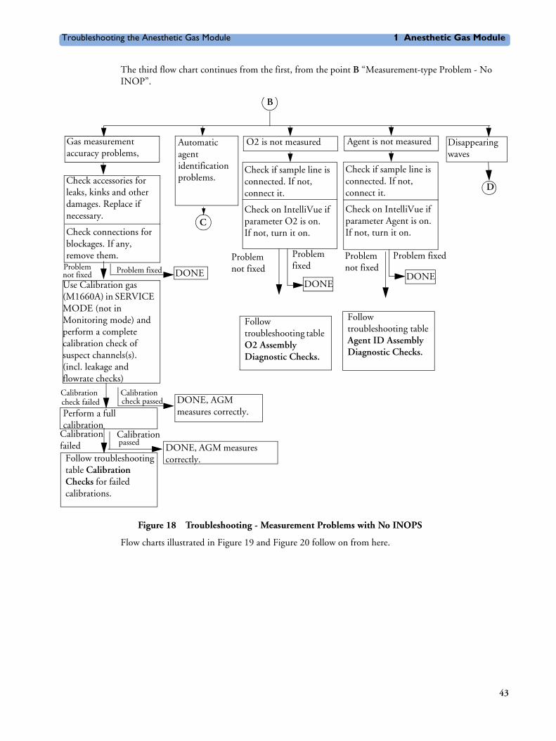
The third flow chart continues from the first, from the point B “Measurement-type Problem - No INOP”.
Figure 18 Troubleshooting - Measurement Problems with No INOPS
Flow charts illustrated in Figure 19 and Figure 20 follow on from here.
B
Gas measurement accuracy problems,
Automatic agent identification problems.
O2 is not measured Disappearing waves
Check accessories for leaks, kinks and other damages. Replace if necessary.
Check connections for blockages. If any, remove them.
Calibration check failed
Calibrationcheck passed
Perform a full calibration
Follow troubleshooting table Calibration Checks for failed calibrations.
Check if sample line is connected. If not, connect it.
Check on IntelliVue if parameter O2 is on.If not, turn it on.
DONEDONE
DONE, AGM measures correctly.
DONE, AGM measures correctly.
Problemnot fixed
Problem fixed
Calibration failed
Calibrationpassed
C
D
Problem fixed
Problemnot fixed
Follow troubleshooting table O2 Assembly Diagnostic Checks.
Agent is not measured
Check if sample line is connected. If not, connect it.
Check on IntelliVue if parameter Agent is on.If not, turn it on.
DONE
Problem fixedProblemnot fixed
Follow troubleshooting table Agent ID Assembly Diagnostic Checks.
Use Calibration gas (M1660A) in SERVICE MODE (not in Monitoring mode) and perform a complete calibration check of suspect channels(s). (incl. leakage and flowrate checks)
43

1 Anesthetic Gas Module Troubleshooting the Anesthetic Gas Module
The fourth flow chart continues from the third, from point C “Agent ID Problems”:
Figure 19 Troubleshooting - Agent ID Problems
The fifth flow chart also continues from the third, from point D “Disappearing Waves”:
Problem not fixed
C
Check for correct agent configuration (auto/manual mode). Correct setting is necessary.
No agentProblem fixed
Check if an agent is administered while the problem is observed.
Use Cal. gas in monitoring mode. Halocarbon 22 must be identified as Halothane (they are very similar).
Check the cable connections of the Agent-ID. Reconnect cables if necessary.
Follow troubleshooting table Agent ID Assembly Diagnostic Checks
DONE
Agent is present No agent present
Problem fixed
Check Agent-ID in Gas Analyzer Diagnostic window.
Agent-ID Agent-ID not reportedreported
Check if there is a change from one agent to another.
Problem Problem fixednot fixed DONE
exchange
DONE
DONE, agent-ID works properlyCorrect identification
No correct
Follow troubleshooting table Agent ID Assembly Diagnostic Checks
Explain that the transit time in the anesthesia circuit is up to 10-15 min. before the new agent can be detected (time until the old agent is washed out, operating with low flow). The INOP “Agent Mixture” identifies an agent exchange (two agents present at one time).
44

Troubleshooting the Anesthetic Gas Module 1 Anesthetic Gas Module
Figure 20 Troubleshooting - Disappearing Waves
Hardware Related Troubleshooting StrategyOverall troubleshooting strategy for hardware related problems/hardware and measurement related AGM INOPs:
1 Always perform a leak and flowrate check before continuing any other troubleshooting. If any check fails, first fix leak and/or flowrate problem and repeat a zero calibration. Then check whether problems still exist.
There are only two device conditions that make it impossible to perform a leak/flowrate check:
– Pump is not running:
Check for proper electrical connection and check that AGM is not in Standby Mode. If OK, replace pump.
– INOP "GAS AN. EQUIP MALF": see “INOPs” on page 46.
2 After the first zero calibration, always check which AGM INOP’s are displayed in Monitoring Mode. Refer to “INOPs” on page 46 where you can find a listing of possible root causes and their
Problem not fixed
Disappearing waves in warmup mode.
Wait if it also occurs in normal mode.
Disconnect exhaust tubing if available.
Perform flowrate check and pump test which is provided in the PM kit. I f pump test failes, replace pump, if flow check fails read just and calibrate flowrates.
Keep unit running for >90 min.
Take care that the Gas Analyzer is not configured to go into standby during that time. If standby configuration has to be altered, switch it back again
Check Gas Analyzer Calibration and Diagnostic window and follow troubleshooting tables for reported errors.
D
DONE
DONE
DONE
Problem notfixed
Problem fixed
Problem fixed
Yes No
45

1 Anesthetic Gas Module Troubleshooting the Anesthetic Gas Module
corrective actions to the most common hardware and measurement related AGM INOP’s. Check out the possible problems in the order given in the table!
3 After the first zero calibration, always check which problems are flagged in the Gas Analyzer Diagnostic window. Troubleshoot flagged problems in the Gas Analyzer Diagnostic window following the hierarchy given in “Problem Solving Hierarchy” on page 51 and the related troubleshooting tables and/or troubleshoot zero calibration failures.
INOPsCheck out the possible problems in the order given in the following table.
INOP Possible Problem/Cause Corrective action
GA. NOT AVAILABLE
AGM not switched on. Switch on AGM
AGM not properly connected. Check physical connections.
GA INCOMPATIBLE
This version of the AGM is incompatible with the monitor
Disconnect AGM.
GAEQUIP MALF Either AGM - monitor connection problem, serious problem with a subassembly or Main PC Board problem.
Check RS232 connection, RS232 cable and MIB board of monitor. If ok, check whether status (“OK” or “PROBLEM”) is shown in AG Diag Window. If yes, troubleshoot subassemblies according hierarchy. If status “UNKNOWN” is shown for all assemblies for more than 4 min. after Power On, replace main pcb.
Serious IR measurement head problem.
Check IR head and replace it if necessary, check whether Service Note M1026A-035/038 applies.
GAS OCCLUSION External occlusion (inlet or exhaust accessories).
Disconnect all external tubing/filters and check whether occlusion disappears.
Internal occlusion Troubleshoot internal occlusion and remove it
Weak/defective pump Perform pump test (provided in PM Kit M1026-60132), replace it if necessary.
Leakage between pump and flow restrictor
Check pneumatic path between pump and flow restrictor tubing for leakages
Flow transducer incorrectly connected to flow restrictor
Check that the transducer ports A and B on the Main PC board are connected to the correct side of the flow restrictor.
46

Troubleshooting the Anesthetic Gas Module 1 Anesthetic Gas Module
GA ZERO FAILED Purge Flow out of tolerance. Adjust purge flow and calibrate flow. Repeat zero calibration.
No flow calibration after flow adjustment.
Perform flow calibration
Occlusion during zero calibration. Remove occlusion.
Solenoid 1 defective. Replace solenoid 1.
Measured ambient pressure does not match with configured altitude in ACMS Service Mode (tolerance is +/- 60 mmHg).
Verify correct altitude setting /pressure Cal value. If necessary, adjust it.
IR measurement head problem. Check IR head and replace it if necessary.
O2 ZERO FAILED O2 new zero constants out of range. Troubleshoot O2 sensor and replace it if necessary.
AGENT IDENT ZERO FAILED
Solenoid 2 defective Replace solenoid 2.
Agent-ID problem. Troubleshoot Agent-ID and replace it if necessary.
O2 EQUIP MALF O2 span failed. Check O2 span calibration. If it fails, troubleshoot span calibration/ O2 sensor and replace it if necessary.
O2 is built in, but set to digital 45%. If O2 value is set to digital “45%” in Service Mode, replace the O2 sensor.
AGENT IDENT MALF
Serious Agent-ID problem. Check Agent-ID and replace it if necessary.
XXX MEAS DISTURBED
(XXX: N2O, CO2, agent or O2)
Minor transient IR head problem If it lasts only for a few seconds and clears itself, NO ACTION REQUIRED.
(Minor transient O2 sensor problem if XXX = O2)
If it doesn't clear itself, troubleshoot IR head/ O2 sensor and replace it if necessary.
GAS AN ACCURACY ?
Flow rate error. Check flow (purge and normal), adjust and calibrate if necessary.
No flow calibration after flow adjustment
Perform flow calibration
Partial occlusion. Troubleshoot for occlusion.
IR head problem. Troubleshoot IR head and replace it if necessary.If it lasts only for a few seconds and clears itself, NO ACTION REQUIRED
O2 UNABLE TO MEASURE
Flow rate error. Check flow (purge and normal), adjust and calibrate if necessary
No flow calibration after flow adjustment
Perform flow calibration
INOP Possible Problem/Cause Corrective action
47

1 Anesthetic Gas Module Troubleshooting the Anesthetic Gas Module
Calibration ChecksTo access the Gas Analyzer Calibration window select Gas Analyzer Calibration in the Setup Gas Analyzer menu.
A Passed/Failed indication is displayed for the Zero and the Span calibrations. Refer to the table below for possible causes of Failed indications, and their recommended corrective actions.
O2 data not valid. Troubleshoot O2 sensor and replace it if necessary.
CO2 UNABLE TO MEASURE
CO2 span failed / CO2 data not valid. Check CO2 span calibration. If it fails, troubleshoot span calibration/ IR head and replace it if necessary.
AGT UNABLE TO MEASURE
Agent span failed / Agent data not valid.
Check agent span calibration. If it fails, troubleshoot span calibration/ IR head and replace it if necessary.
N2O UNABLE TO MEASURE
N2O span failed / N2O data not valid.
Check N2O span calibration. If it fails, troubleshoot span calibration/ IR head and replace it if necessary.
INOP Possible Problem/Cause Corrective action
48
Troubleshooting the Anesthetic Gas Module 1 Anesthetic Gas Module
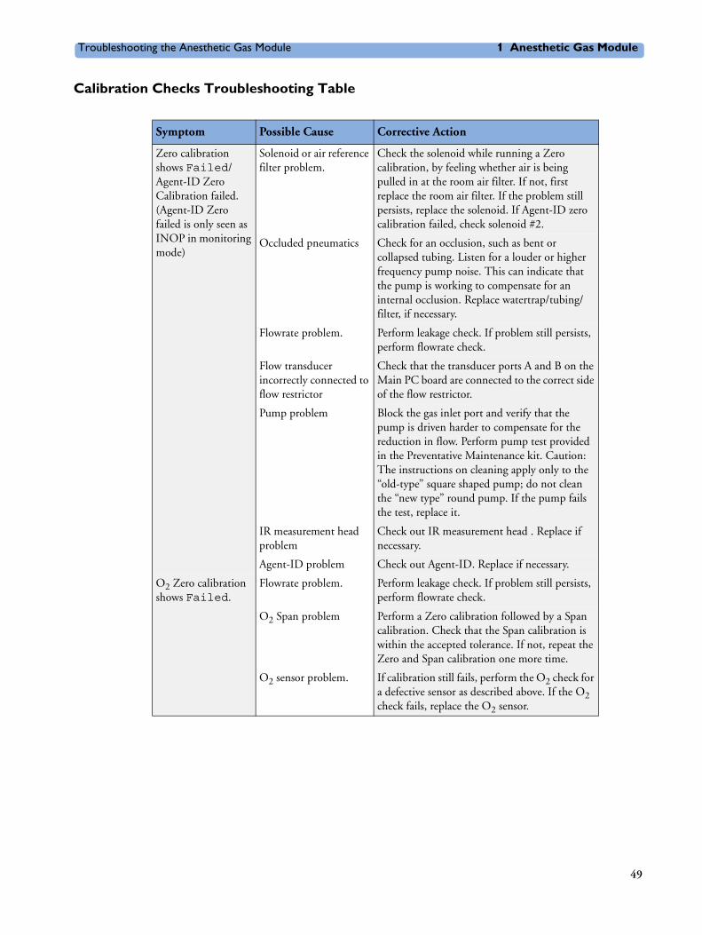
Calibration Checks Troubleshooting Table
Symptom Possible Cause Corrective Action
Zero calibration shows Failed/Agent-ID Zero Calibration failed. (Agent-ID Zero failed is only seen as INOP in monitoring mode)
Solenoid or air reference filter problem.
Check the solenoid while running a Zero calibration, by feeling whether air is being pulled in at the room air filter. If not, first replace the room air filter. If the problem still persists, replace the solenoid. If Agent-ID zero calibration failed, check solenoid #2.
Occluded pneumatics Check for an occlusion, such as bent or collapsed tubing. Listen for a louder or higher frequency pump noise. This can indicate that the pump is working to compensate for an internal occlusion. Replace watertrap/tubing/filter, if necessary.
Flowrate problem. Perform leakage check. If problem still persists, perform flowrate check.
Flow transducer incorrectly connected to flow restrictor
Check that the transducer ports A and B on the Main PC board are connected to the correct side of the flow restrictor.
Pump problem Block the gas inlet port and verify that the pump is driven harder to compensate for the reduction in flow. Perform pump test provided in the Preventative Maintenance kit. Caution: The instructions on cleaning apply only to the “old-type” square shaped pump; do not clean the “new type” round pump. If the pump fails the test, replace it.
IR measurement head problem
Check out IR measurement head . Replace if necessary.
Agent-ID problem Check out Agent-ID. Replace if necessary.
O2 Zero calibration shows Failed.
Flowrate problem. Perform leakage check. If problem still persists, perform flowrate check.
O2 Span problem Perform a Zero calibration followed by a Span calibration. Check that the Span calibration is within the accepted tolerance. If not, repeat the Zero and Span calibration one more time.
O2 sensor problem. If calibration still fails, perform the O2 check for a defective sensor as described above. If the O2 check fails, replace the O2 sensor.
49

1 Anesthetic Gas Module Troubleshooting the Anesthetic Gas Module
Diagnostic Checks
WARNING If you carry out checks with replacement parts, be aware of the high-voltage locations. Never remove cables or sub-assemblies while the Module is powered on.
To access the Gas Analyzer Diagnostic window select Gas Analyzer Diagnostic in the Setup Gas Analyzer menu.
Span calibration shows Failed (for O2, N2O, CO2, agent).
Zero calibration failed for the indicated channel.
Follow corrective actions for failed Zero calibration described above.
Agent selection or calibration values (CalValue) incorrect
Check for proper selection of Agent and calibration values .
Flowrate problem. Check the flowrate.
Leakage problem. Perform leakage check. Check integrity of tubing and replace if necessary.
Wrong gas applied. Check the label on the gas canister.
Calibration reservoir bag empty or calibration gas canister empty.
Check that there is enough gas available.
Measurement assembly problem.
Check the Gas Analyzer Diagnosticwindow for a Measurement assembly problem. If a problem is flagged, follow corrective actions as described in the troubleshooting tables. After that, or if no problem was flagged, return to the Gas Analyzer Calibration window. If the failed status is still shown against Span Calibration, repeat the Span calibration. After that, perform a Zero calibration.
O2 Span calibration shows Failed.
O2 sensor problem. Check O2 sensor problem as described above.
Symptom Possible Cause Corrective Action
50

Troubleshooting the Anesthetic Gas Module 1 Anesthetic Gas Module
Figure 21 Gas Analyzer Diagnostic Window
Problem Solving HierarchyTo help identify a problem, a OK/Problem message is displayed for major subassemblies. If a problem is displayed use the following pages to isolate the problem according to the following hierarchy (this hierarchy overrides the sequence shown on the display):
1 Pneumatic System
2 IR Measurement Assembly (Meas. Assy)
3 Optical Path (Meas. Optic. Path)
4 O2 Assembly (O2 Assy)
5 Agent ID Assembly (Agt-Id Assy)
6 Power Supply
7 Operating Temperature
The Gas Analyzer Diagnostic window also displays the number of pump operation hours.
NOTE To remove the top cover, refer to the section The Top Cover.
Refer to the following tables for possible causes of Problem indications, and their recommended corrective actions.
51
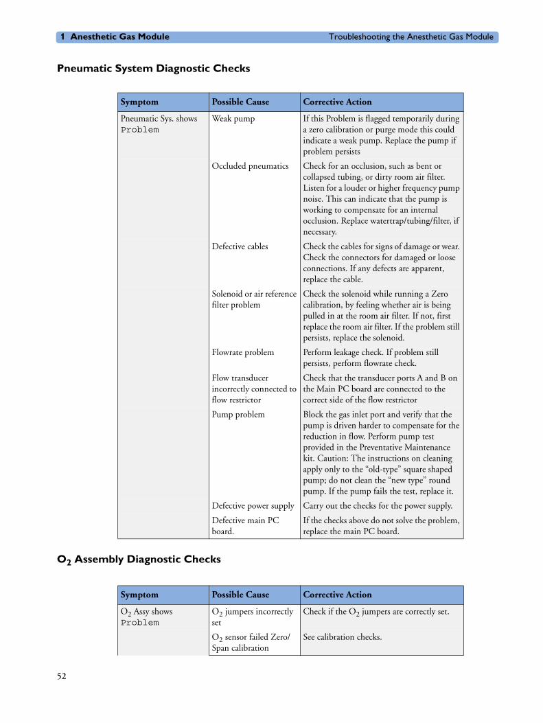
1 Anesthetic Gas Module Troubleshooting the Anesthetic Gas Module
Pneumatic System Diagnostic Checks
O2 Assembly Diagnostic Checks
Symptom Possible Cause Corrective Action
Pneumatic Sys. shows Problem
Weak pump If this Problem is flagged temporarily during a zero calibration or purge mode this could indicate a weak pump. Replace the pump if problem persists
Occluded pneumatics Check for an occlusion, such as bent or collapsed tubing, or dirty room air filter. Listen for a louder or higher frequency pump noise. This can indicate that the pump is working to compensate for an internal occlusion. Replace watertrap/tubing/filter, if necessary.
Defective cables Check the cables for signs of damage or wear. Check the connectors for damaged or loose connections. If any defects are apparent, replace the cable.
Solenoid or air reference filter problem
Check the solenoid while running a Zero calibration, by feeling whether air is being pulled in at the room air filter. If not, first replace the room air filter. If the problem still persists, replace the solenoid.
Flowrate problem Perform leakage check. If problem still persists, perform flowrate check.
Flow transducer incorrectly connected to flow restrictor
Check that the transducer ports A and B on the Main PC board are connected to the correct side of the flow restrictor
Pump problem Block the gas inlet port and verify that the pump is driven harder to compensate for the reduction in flow. Perform pump test provided in the Preventative Maintenance kit. Caution: The instructions on cleaning apply only to the “old-type” square shaped pump; do not clean the “new type” round pump. If the pump fails the test, replace it.
Defective power supply Carry out the checks for the power supply.
Defective main PC board.
If the checks above do not solve the problem, replace the main PC board.
Symptom Possible Cause Corrective Action
O2 Assy shows Problem
O2 jumpers incorrectly set
Check if the O2 jumpers are correctly set.
O2 sensor failed Zero/Span calibration
See calibration checks.
52

Troubleshooting the Anesthetic Gas Module 1 Anesthetic Gas Module
Defective O2 sensor If two solenoids are installed, disconnect cable of solenoid #2 (near O2 sensor).
Go into Gas Analyzer Calibration window
Start a zero calibration to get the actual barometric pressure reading.
Note the measured barometric pressure in mmHg displayed in the Calibration window
Using a voltmeter, check the O2 sensor voltage as follows:
Connect voltmeter ground to TP1.
Measure TP8 voltage. 1% O2 is approximately equal to 10mV.
As the O2 measurement is influenced by the barometric pressure, the correct voltage must be calculated as follows:
O2 concentration of gas in mV multiplied by the measured barometric pressure in mmHg and divided by 760 mmHg.
For example, correct calculated voltage for room air (20.9% O2) and barometric pressure of 720 mmHg is: 209 mV x 720 mmHg / 760 mmHg = 198mV.
If the voltage is not within ±10% of calculated value, proceed to adjust O2 Zero and Span potentiometers in the following order:
Table continued on next page.
Symptom Possible Cause Corrective Action
53

1 Anesthetic Gas Module Troubleshooting the Anesthetic Gas Module
Zero Adjust:
Calculate the correct voltage as described above using the actual room air O2 concentration and measured barometric pressure. Adjust RV2 potentiometer on the PC Board until the voltmeter reads the calculated voltage ±1mV. You can also use a gas which does not contain O2 and adjust RV2 potentiometer on the PC Board until the voltmeter reading is 0 mV ±1mV. The gas must be applied at the room air filter.
Span Adjust:
Apply Philips Calibration Gas M1660A (containing 52% O2) to the room air filter (connect the calibration tubing to the open end of the room air filter). Calculate the correct voltage as described above using the specific O2 concentration and measured barometric pressure. Adjust RV1 until the voltmeter reads the calculated voltage ±10 mV. Disconnect the calibration tubing from the room air filter.
Reconnect cable of solenoid #2 if it was disconnected.
If these adjustments are not successful, check the pneumatic system for leakages If the problem still persists, replace the O2 sensor.
If any adjustment was necessary, perform a Zero calibration followed by an O2 Span calibration.
Defective cables. Check the cables connecting the O2 assembly and the main PC board for signs of damage or wear. Check the connectors for damaged or loose connections. If any defects are apparent, replace the cable.
Defective power supply Carry out the checks for the power supply .
Defective main PC board.
If the checks above do not solve the problem, replace the main PC board.
Symptom Possible Cause Corrective Action
54

Troubleshooting the Anesthetic Gas Module 1 Anesthetic Gas Module
Optical Path Disgnostic Checks
Symptom Possible Cause Corrective Action
MeasOpticPath shows Problem
Defective or contaminated sample cell
Remove the sample cell and visually check it to see if it is contaminated. The inside of the cell should be smooth and shiny. If not, replace the sample cell. Wait after the first Zero Calibration to see whether the problem disappears.
If problems are cleared after warm-up, but were present during warm-up, let the AGM run for at least 90 minutes after Power On to allow the unit to reach the 90 minutes zero. This is a special zero calibration where "new" zero constants for the next warm-up phase are stored. This prevents that problems are flagged during the next warm-up phase
Defective IR measurement assembly head
Carry out the checks for the IR measurement assembly head . With the replacement head connected, check that Optical Path problem is no longer flagged. If the problem is gone, use a new head. If not, continue checks as described below.
Defective power supply Carry out the checks for the power supply .
Defective main PC board
If the checks above do not solve the problem, replace the main PC board.
55

1 Anesthetic Gas Module Troubleshooting the Anesthetic Gas Module
IR Measurement Assembly Diagnostic Checks
Symptom Possible Cause Corrective Action
Meas. Assy shows Problem
Defective IR measurement assembly head
Do the following IR measurement assembly head checks:
Check whether Service Note M1026A-035/038 applies
Remove the sample cell (see Repairing the Anesthetic Gas Module) and visually check it to see if it is contaminated. The inside of the cell should be smooth and shiny.
Perform flow and Span gas calibration (in order to store new reference values)
Using a voltmeter, check the IR source voltage as follows:
Connect the voltmeter ground to TP1.
Measure TP6 voltage. It should be 7.87V ±20mV.
If this voltage is within limits, proceed to the next check. If not, adjust the potentiometer R178 to the required value. If the adjustment is not possible, replace the measurement assembly head.
Power off. Connect a replacement head with the ribbon cable and reconnect the tubing. Turn power back on and see if the Meas. Assy still shows Problem. If the message is gone, replace the head. If the problem persists, continue checking.
Defective power supply Carry out the checks for the power supply .
Defective cables Check the cables connecting the measurement head and the main PC board for signs of damage or wear. Check the connectors for damaged or loose connections. If any defects are apparent, replace the cable.
Defective main PC board
If the checks above do not solve the problem, replace the main PC board.
56

Troubleshooting the Anesthetic Gas Module 1 Anesthetic Gas Module
Agent ID Assmebly Diagnostic Checks
Symptom Possible Cause Corrective Action
Agt-ID. Assy shows Problem
Wrong Agent-ID software revision
Check for correct Agent-ID revision in AG Revision window, item:
Agt-ID SW
If necessary, replace Agent-ID EPROM.
Defective agent ID head.
Do the following agent ID head checks:
Using a voltmeter, check the IR source voltage at the main PC board as follows:
Connect the voltmeter ground to TP1.
Measure TP11 voltage. It should be 7.92V ±20mV.
If this voltage is within limits, proceed to the next check. If not, adjust the potentiometer R180 to the required value. If adjustment is not possible, replace the Agent-ID head.
Power off. Connect a replacement head with the ribbon cable and reconnect tubing. Turn power back on and see if the Agt.-Id still shows Problem. If the message is gone, replace the head. If the problem persists, continue checking. Power Supply Diagnostic Checks
Defective power supply Carry out the checks for the power supply .
Defective cables Check the cables connecting the measurement head and the main PC board for signs of damage or wear. Check the connectors for damaged or loose connections. If any defects are apparent, replace the cable.
Defective main PC board
If the checks above do not solve the problem, replace the main PC board.
57

1 Anesthetic Gas Module Troubleshooting the Anesthetic Gas Module
Power Supply Diagnostic Checks
Symptom Possible Cause Corrective Action
Power Supply shows Problem
Weak pump If this Problem is flagged temporarily during a zero calibration or purge mode this could indicate a weak pump. Replace the pump if problem persists
Defective power supply Using a voltmeter, check the power supply voltages at the main PC board. The power supply connectors should carry the following voltages:
TP14: +12V ±600 mV
TP15: +5V ±250 mV
TP16: -12V ±600 mV
TP17: +12V ±600 mV
TP18: Analog Ground
If any of the above voltages are out of limits, carry out the checks again while systematically disconnecting the subassemblies (remember to power off the Module before removing cables and subassemblies). If the voltage(s) are still out of limits, replace the power supply.
Defective cables Check the cables connecting the measurement head and the main PC board for signs of damage or wear. Check the connectors for damaged or loose connections. If any defects are apparent, replace the cable.
Defective main PC board
If the checks above do not solve the problem, replace the main PC board.
58
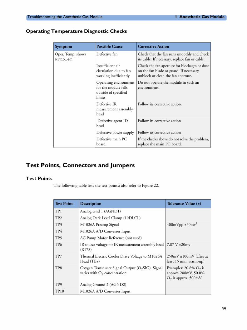
Troubleshooting the Anesthetic Gas Module 1 Anesthetic Gas Module
Operating Temperature Diagnostic Checks
Test Points, Connectors and Jumpers
Test PointsThe following table lists the test points; also refer to Figure 22.
Symptom Possible Cause Corrective Action
Oper. Temp. shows Problem
Defective fan Check that the fan runs smoothly and check its cable. If necessary, replace fan or cable.
Insufficient air circulation due to fan working inefficiently
Check the fan aperture for blockages or dust on the fan blade or guard. If necessary, unblock or clean the fan aperture.
Operating environment for the module falls outside of specified limits
Do not operate the module in such an environment.
Defective IR measurement assembly head
Follow its corrective action.
Defective agent ID head
Follow its corrective action
Defective power supply Follow its corrective action
Defective main PC board.
If the checks above do not solve the problem, replace the main PC board.
Test Point Description Tolerance Value (±)
TP1 Analog Gnd 1 (AGND1)
TP2 Analog Dark Level Clamp (10DLCL)
TP3 M1026A Preamp Signal 400mVpp ±30mv1
TP4 M1026A A/D Converter Input
TP5 AC Pump Motor Reference (not used)
TP6 IR source voltage for IR measurement assembly head (R178)
7.87 V ±20mv
TP7 Thermal Electric Cooler Drive Voltage to M1026A Head (TE+)
250mV ±100mV (after at least 15 min. warm-up)
TP8 Oxygen Transducer Signal Output (O2SIG). Signal varies with O2 concentration.
Examples: 20.8% O2 is approx. 208mV, 50.0% O2 is approx. 500mV
TP9 Analog Ground 2 (AGND2)
TP10 M1026A A/D Converter Input
59

1 Anesthetic Gas Module Troubleshooting the Anesthetic Gas Module
ConnectorsThe following table lists the connectors on the main PCB.
JumpersThe following table shows the correct jumper settings for the O2 sensor (if installed).
TP11 IR source voltage for agent ID head (R180) 7.92 V ±20mV
TP13 Isolated Ground for isolated RS-232 communications with the Host Computer via J14
TP14 +12VHP +12V ±600mV
TP15 +5V +5V ±250mV
TP16 -12V -12V ±600mV
TP17 +12V +12V ±600mV
TP18 Analog Ground 3 (AGND3) 1. Measurement requires an oscilloscope.
Test Point Description Tolerance Value (±)
Connector Description
J1 IR Measurement Assembly Head
J2 Agent ID Head
J3 Factory use only
J4 Factory use only
J5 DC Power: pins 1&2: +12VHP, pins 3&4: +5V GND (DGND), pin 6: AGND, pin 7: AGND, pin 8: -12V, pin 9: +12V
J6 PC Board connector (also for NVRAM data transfer)
JP7 Top cover jumper
J8 Pump driver for DC pump and AC pump (DC PUMP/AC PUMP)1
1. Use DC pump only.
J10 Oxygen Transducer Connection
J13 Factory use only
J14 Connection to Host Computer for communications, RS-232
J15 Fan power (FAN1)
J16 Not used
J17 Power LED
J19 Factory use only
J20 Factory use only
J21 O2 Solenoid (SOL2)
J22 Optional Front Panel I/O
60

Troubleshooting the Anesthetic Gas Module 1 Anesthetic Gas Module
The top cover Jumper, JP7, must always be closed, whether or not the top cover is connected.
Figure 22 Potentiometers, Jumpers, and Test Points
Legend:
Jumper Paramagnetic O2 Sensor No O2 Sensor
10IRQ1 OPEN OPEN
10IRQ2 OPEN OPEN
10IRQ3 CLOSED OPEN
Main EPROMAgt-ID EPROM
U11
1 Flowrate potentiometers (R125, Purge flow and R126, Normal flow)
2 IR Source potentiometers (R178, R180)
3 O2 jumper (10IRQ)
4 Top cover jumper (JP7)
5 EPROMs
6 Microprocessors
7 Test pins
61

1 Anesthetic Gas Module Repairing the Anesthetic Gas Module
Repairing the Anesthetic Gas Module
Introduction This section contains detailed removal and replacement procedures for all field-replaceable units in the Philips M1026A Anesthetic Gas Module.
CAUTION Use caution when handling tubing and other components of the patient circuit. Wear gloves, mask and gown while handling components that come into contact with the patient’s exhalant gas or fluids.
Before you can remove any of these field replaceable units, you first need to remove the top cover of the Anesthetic Gas Module. The procedure for this is described in “The Top Cover” on page 64.
WARNING Switch off the instrument and disconnect it from the mains power supply. Take standard electrostatic precautions. For example, a wrist strap connected to electrical ground.
Figure 23 shows the field-replaceable units for the Anesthetic Gas Module. These are:
• Top Cover
• Infrared (IR) Measurement Assembly (2)
• Sample Cell
• Solenoid Valve #1 (7)
• Power Supply Unit (1)
• Main PC Board (13)
• O2 Paramagnetic Assembly (11)
• Agent Identification Head (9)
• Pump (3)
• Fan (5)
• Solenoid Valve #2 (10)
• Top Cover PC Board (15)
• PM Kit comprising:
– Room Air Filter (6)
– Nafion Tubing and internal bacterial filters(12)
– Watertrap manifold seals
– Pump Filter (4)
• Watertrap Manifold and Protector
8 Flow transducer
9 Top-cover PC board connector / NVRAM transfer
62
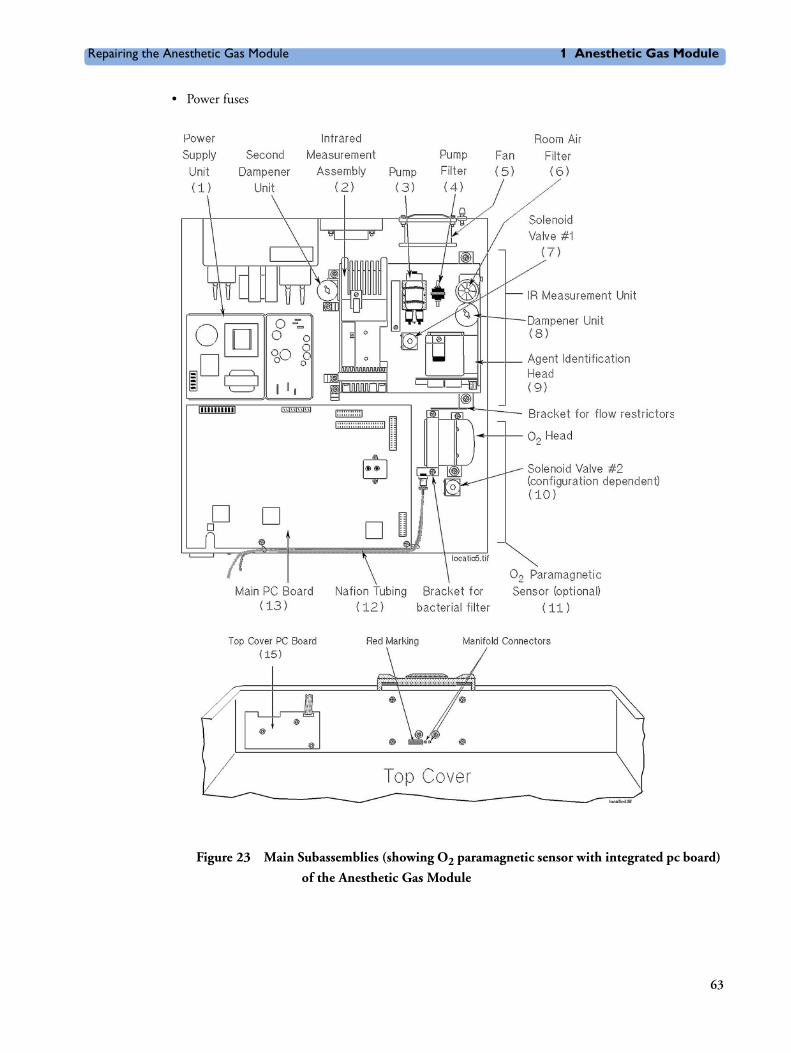
Repairing the Anesthetic Gas Module 1 Anesthetic Gas Module
• Power fuses
Figure 23 Main Subassemblies (showing O2 paramagnetic sensor with integrated pc board)
of the Anesthetic Gas Module
63
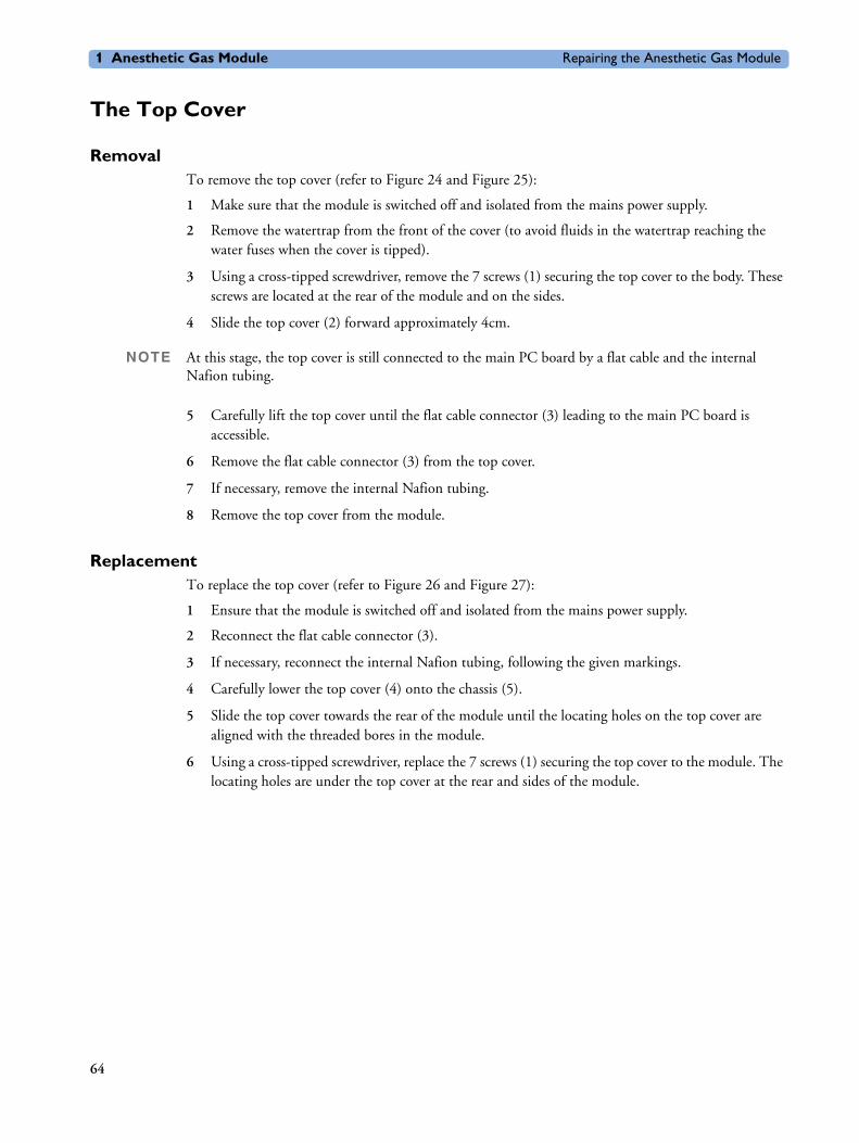
1 Anesthetic Gas Module Repairing the Anesthetic Gas Module
The Top Cover
Removal To remove the top cover (refer to Figure 24 and Figure 25):
1 Make sure that the module is switched off and isolated from the mains power supply.
2 Remove the watertrap from the front of the cover (to avoid fluids in the watertrap reaching the water fuses when the cover is tipped).
3 Using a cross-tipped screwdriver, remove the 7 screws (1) securing the top cover to the body. These screws are located at the rear of the module and on the sides.
4 Slide the top cover (2) forward approximately 4cm.
NOTE At this stage, the top cover is still connected to the main PC board by a flat cable and the internal Nafion tubing.
5 Carefully lift the top cover until the flat cable connector (3) leading to the main PC board is accessible.
6 Remove the flat cable connector (3) from the top cover.
7 If necessary, remove the internal Nafion tubing.
8 Remove the top cover from the module.
Replacement To replace the top cover (refer to Figure 26 and Figure 27):
1 Ensure that the module is switched off and isolated from the mains power supply.
2 Reconnect the flat cable connector (3).
3 If necessary, reconnect the internal Nafion tubing, following the given markings.
4 Carefully lower the top cover (4) onto the chassis (5).
5 Slide the top cover towards the rear of the module until the locating holes on the top cover are aligned with the threaded bores in the module.
6 Using a cross-tipped screwdriver, replace the 7 screws (1) securing the top cover to the module. The locating holes are under the top cover at the rear and sides of the module.
64

Repairing the Anesthetic Gas Module 1 Anesthetic Gas Module
Figure 24 Top Cover Securing Screws for the Anesthetic Gas Module
Figure 25 Sliding Off the Top Cover of the Anesthetic Gas Module
RS 232
MONITOR
100-240V
T1.6 H 250V
600VA max.
brear2d.tif
60/140
50-60 Hz
1
65
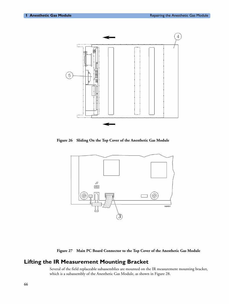
1 Anesthetic Gas Module Repairing the Anesthetic Gas Module
Figure 26 Sliding On the Top Cover of the Anesthetic Gas Module
Figure 27 Main PC Board Connector to the Top Cover of the Anesthetic Gas Module
Lifting the IR Measurement Mounting BracketSeveral of the field replaceable subassemblies are mounted on the IR measurement mounting bracket, which is a subassembly of the Anesthetic Gas Module, as shown in Figure 28.
3
66

Repairing the Anesthetic Gas Module 1 Anesthetic Gas Module
The IR assembly mounting bracket must first be lifted and stood on end before any of the following units can be removed or replaced:
• IR measurement assembly and sample cell.
• Solenoid valve #1.
Removal To lift the IR Measurement mounting bracket (refer to Figure 28 and Figure 29):
1 Ensure that the module is switched off and isolated from the mains power supply. Remove the top cover of the module.
2 Remove the cables from the cable clip.
3 Remove the connection from the gas exhaust (1).
4 Using a cross-tipped screwdriver, remove the four screws and lock washers (2) securing the IR Measurement mounting bracket to the module.
5 Lift the IR Measurement mounting bracket and stand it carefully on its end, so that the ribbon cables are at the bottom. The securing screws on the underside are now accessible, as shown in Figure 29.
Replacement To replace the IR Measurement mounting bracket (refer to Figure 28 and Figure 29):
1 Ensure that the module is switched off and isolated from the mains power supply.
2 Lay the IR Measurement mounting bracket carefully onto its 4 spacers so that the locating holes are aligned with the threaded bores.
3 Make sure that the dampener (3), cable clamp (4) and bracket with flow restrictor (5) are in place. Using a cross-tipped screwdriver, fit the four screws and lock washers (2) securing the IR Measurement mounting bracket to the module.
4 Reconnect the pneumatic tubing to the gas exhaust (1).
5 Replace the power connection to the pump (where applicable) and secure the cables with the clip.
6 Replace the top cover of the module.
NOTE After replacing the IR Measurement mounting bracket, check that all flat-cable connectors are firmly seated and show no signs of damage.
67

1 Anesthetic Gas Module Repairing the Anesthetic Gas Module
Figure 28 Lifting the IR Measurement Mounting Bracket
68
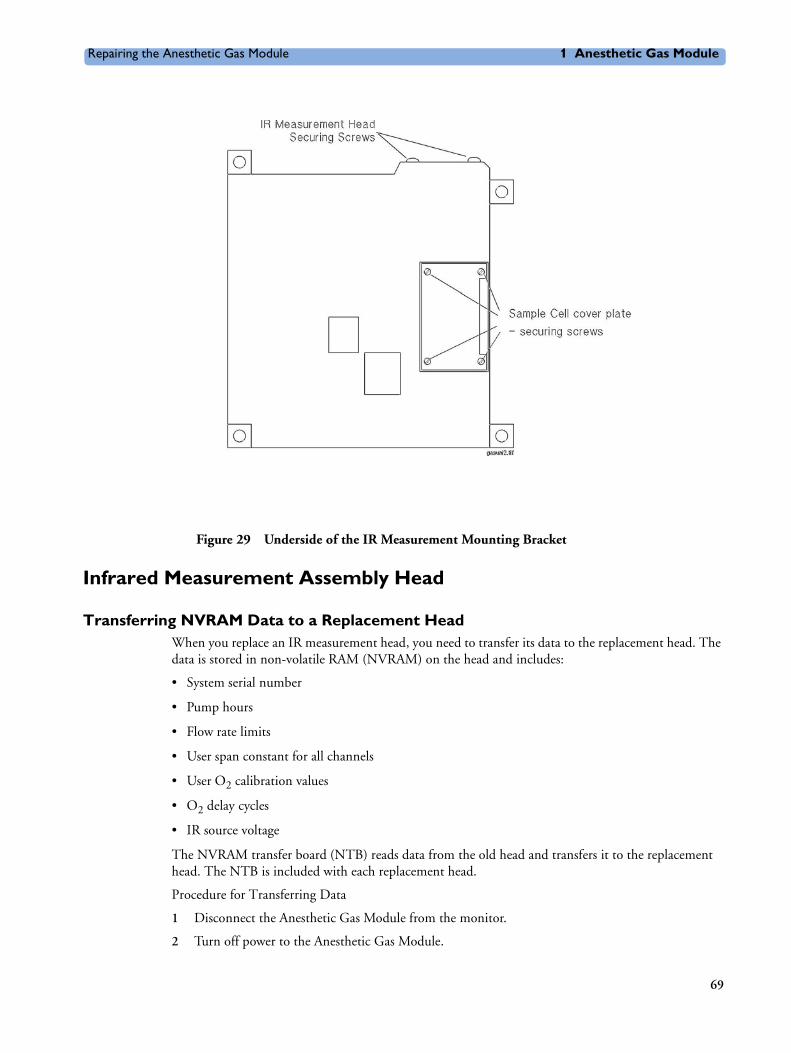
Repairing the Anesthetic Gas Module 1 Anesthetic Gas Module
Figure 29 Underside of the IR Measurement Mounting Bracket
Infrared Measurement Assembly Head
Transferring NVRAM Data to a Replacement HeadWhen you replace an IR measurement head, you need to transfer its data to the replacement head. The data is stored in non-volatile RAM (NVRAM) on the head and includes:
• System serial number
• Pump hours
• Flow rate limits
• User span constant for all channels
• User O2 calibration values
• O2 delay cycles
• IR source voltage
The NVRAM transfer board (NTB) reads data from the old head and transfers it to the replacement head. The NTB is included with each replacement head.
Procedure for Transferring Data
1 Disconnect the Anesthetic Gas Module from the monitor.
2 Turn off power to the Anesthetic Gas Module.
69

1 Anesthetic Gas Module Repairing the Anesthetic Gas Module
3 Remove the Anesthetic Gas Module top cover and disconnect it from the Main PC board.
4 Connect the 40-pin cable of the NTB to the 40-pin connector of the new replacement IR Measurement head.
5 Connect the 10-pin cable of the NTB to the top cover connector (J6) on the Main PC board.
6 Power up the Anesthetic Gas Module and observe the LED on the NTB.
7 For about the first 5 seconds the LED on the NTB will be amber. Whenever the LED is amber, the NTB is processing information and you must stand by until the LED changes color again. During these first 5 seconds, the NVRAMs of both the old and the new measurement heads are being read and checked. If the LED changes to a solid green color, the NVRAM transfer process can begin. Please skip to step 8 if the LED is green.
When either NVRAM cannot be read, it may take up to one minute before the LED changes color and you will observe one of two error conditions:
– If the LED changes to a solid red color, a problem reading the old measurement head has occurred. Turn off the power and check all connections. Make sure the ribbon cables are not broken and correctly seated. Repeat the procedure staring with step 6.
If the LED is still on red, proceed with the installation of the new analyzer head regardless. The NVRAM transfer will not be possible, but the replacement head has default information for pump hours and no serial number. However, before installing the new measurement head, you need to verify that the head is functional:
a. Replace the old measurement head with the new one.
b. Repeat the NVRAM transfer procedure from step 6.
If the LED blinks alternately red and green, the head is functional and you can continue with the installation of the new head. If the LED is solid red, either the new head and/or the cable from the head to the main PC board is defective. In this case you must replace the head or the cable or both.
NOTE When installing a new measurement head and using the default NVRAM data, a flow rate calibration must be performed because no flow rates will be transferred. If no flow rate calibration is performed, a problem with the pneumatic system will be flagged during Anesthetic Gas Module operation.
– If the LED blinks alternately red and green, a problem occurred reading the new analyzer head. Turn off the power and check all connections. Make sure the ribbon cables are not broken and correctly seated. Repeat the procedure staring with step 6.
If the LED is still blinking red and green you need to check whether the failed NVRAM transfer is due to a defective NTB and/or cable connection:
a. Replace the old measurement head with the new one.
b. Repeat the NVRAM transfer procedure from step 6.
If the LED is solid red, the new measurement head is defective. In this case you must use a new replacement measurement head and return to step 4. If the LED blinks alternately green and red, the NTB and/or the attached cables are defective. In this case you need to use a new NTB, or you can install the new measurement head with the default NVRAM data.
70

Repairing the Anesthetic Gas Module 1 Anesthetic Gas Module
8 Once the LED is on green, you can begin the NVRAM transfer process by pressing the momentary push button switch on the NTB. The LED will change to amber for about 5 seconds, followed by solid green indicating a good transfer of NVRAM data.
If you observe a blinking red LED, no transfer or a bad transfer of NVRAM data occurred. Proceed with the installation of the new measurement head regardless. The NVRAM transfer will not be possible, but the replacement head has default information for pump hours and no serial number. However, a flow rate calibration must be performed because no flow rates will be transferred. If no flow rate calibration is performed, a problem with the pneumatic system will be flagged during Anesthetic Gas Module operation.
9 If step 8 was successful, the Anesthetic Gas Module can now be powered off. The NTB can be disconnected and the old measurement head removed and replaced with the new head (see removal and replacement procedure below).
10 Reconnect the Anesthetic Gas Module to the monitor.
NOTE When returning the defective measurement head for repair, make sure to return the NVRAM transfer board with the head.
Instructions for the transfer procedure are also included with the NTB.
Removal
To remove the IR measurement assembly head (refer to Figure 30 and Figure 31):
1 Remove the flat-cable (1) connector from the main PC board.
2 Remove the pneumatic connections (2) from the sample cell, which are located on top of the IR measurement assembly head.
3 Remove the pressure transducer connection (3) located on the side of the IR measurement assembly head.
4 Stand the IR measurement mounting bracket on end (refer to “Lifting the IR Measurement Mounting Bracket” on page 66).
5 Using a cross-tipped screwdriver, remove the 3 screws (4) securing the IR measurement assembly head to the IR measurement mounting bracket.
6 Remove the IR measurement assembly head carefully from the IR measurement mounting bracket.
Replacement
To replace the IR measurement assembly head (refer to Figure 30 and Figure 31):
1 Place the IR measurement assembly head in the IR measurement mounting bracket so that the threaded bores on the head align with their corresponding locating holes on the IR measurement mounting bracket.
2 Using a cross-tipped screwdriver, replace the three screws (4) securing the IR measurement assembly head to the IR measurement mounting bracket.
3 Replace the IR measurement mounting bracket (refer to “Lifting the IR Measurement Mounting Bracket” on page 66).
4 Replace the transducer reference connection (3) located on the side of the IR measurement assembly head.
71
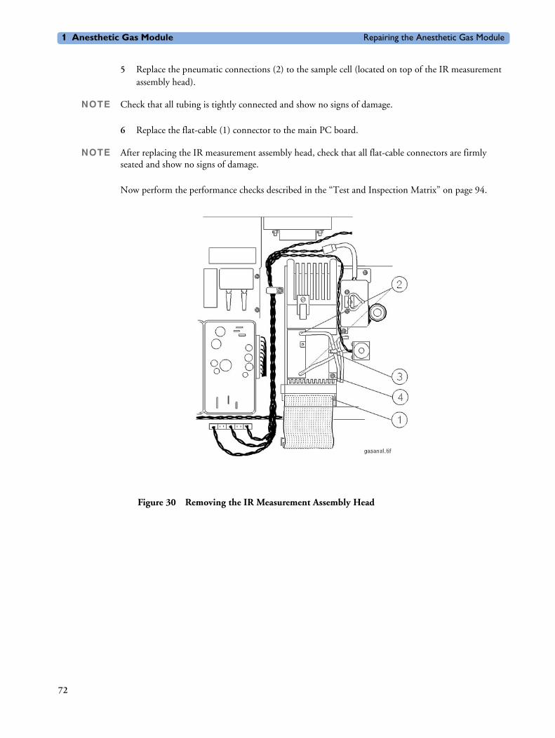
1 Anesthetic Gas Module Repairing the Anesthetic Gas Module
5 Replace the pneumatic connections (2) to the sample cell (located on top of the IR measurement assembly head).
NOTE Check that all tubing is tightly connected and show no signs of damage.
6 Replace the flat-cable (1) connector to the main PC board.
NOTE After replacing the IR measurement assembly head, check that all flat-cable connectors are firmly seated and show no signs of damage.
Now perform the performance checks described in the “Test and Inspection Matrix” on page 94.
Figure 30 Removing the IR Measurement Assembly Head
72

Repairing the Anesthetic Gas Module 1 Anesthetic Gas Module
Figure 31 Locating Screws for the IR Measurement Assembly Head
Sample Cell
RemovalTo remove the sample cell (refer to Figure 32, Figure 33, Figure 34 and Figure 35):
1 Stand the IR measurement mounting bracket on end, towards the main PC board (refer to “Lifting the IR Measurement Mounting Bracket” on page 66).
2 Remove the pneumatic connections (1) from the sample cell, which are located on top of the IR measurement assembly head.
3 Using a cross-tipped screwdriver, remove the four screws (2) securing the sample cell cover plate and bracket (3) from the IR measurement assembly head. Retain these parts for later replacement.
4 Lay the IR measurement assembly head flat and, using a flat-tipped screwdriver, apply pressure from above to the overlapping part (4) of the sample cell cover, and pry it off.
5 Carefully withdraw the sample cover and bracket (5) from the IR measurement head.
6 Using a cross-tipped screwdriver, remove the screw (6) securing the clamping plate (7) to the sample cell bracket (8).
7 Remove the sample cell (9).
Replacement To replace the sample cell (refer to Figure 32, Figure 33, Figure 34 and Figure 35):
73

1 Anesthetic Gas Module Repairing the Anesthetic Gas Module
1 Position the sample cell (9) onto its bracket (8) and hold it in place with the clamping plate (7).
2 Using a cross-tipped screwdriver, replace the screw (6) securing the clamping plate to the bracket. Before tightening the screw, ensure that the pipes to the sample cell are aligned parallel with the sides of the bracket.
NOTE Make sure the temperature sensor has not slipped out of its hole. This can prevent the bracket from being pushed home.
3 Insert the sample cell bracket and cover (5) into the base of the IR measurement assembly head. Push the bracket home so that the surface of the cover plate is flush with the base of the IR measurement head. The two gas tubes should now protrude from the holes (1) on top of the IR measurement head.
4 Using a cross-tipped screwdriver, replace the four screws (2) securing the sample cell cover plate and bracket (3) to the IR measurement assembly head.
5 Replace the pneumatic connections (1) to the sample cell, which are located on top of the IR measurement head.
NOTE Check that all tubing is tightly connected and show no signs of damage.
6 Replace the IR measurement mounting bracket (refer to “Lifting the IR Measurement Mounting Bracket” on page 66).
NOTE After replacing the sample cell, check that all flat-cable connectors are firmly seated and show no signs of damage.
Now perform the performance checks described in the “Test and Inspection Matrix” on page 94.
74

Repairing the Anesthetic Gas Module 1 Anesthetic Gas Module
Figure 32 Removing the Sample Cell Pneumatic Connections
75
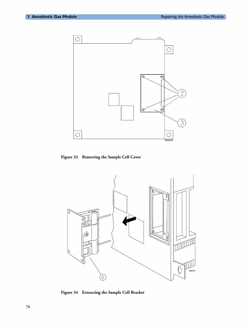
1 Anesthetic Gas Module Repairing the Anesthetic Gas Module
Figure 33 Removing the Sample Cell Cover
Figure 34 Extracting the Sample Cell Bracket
76
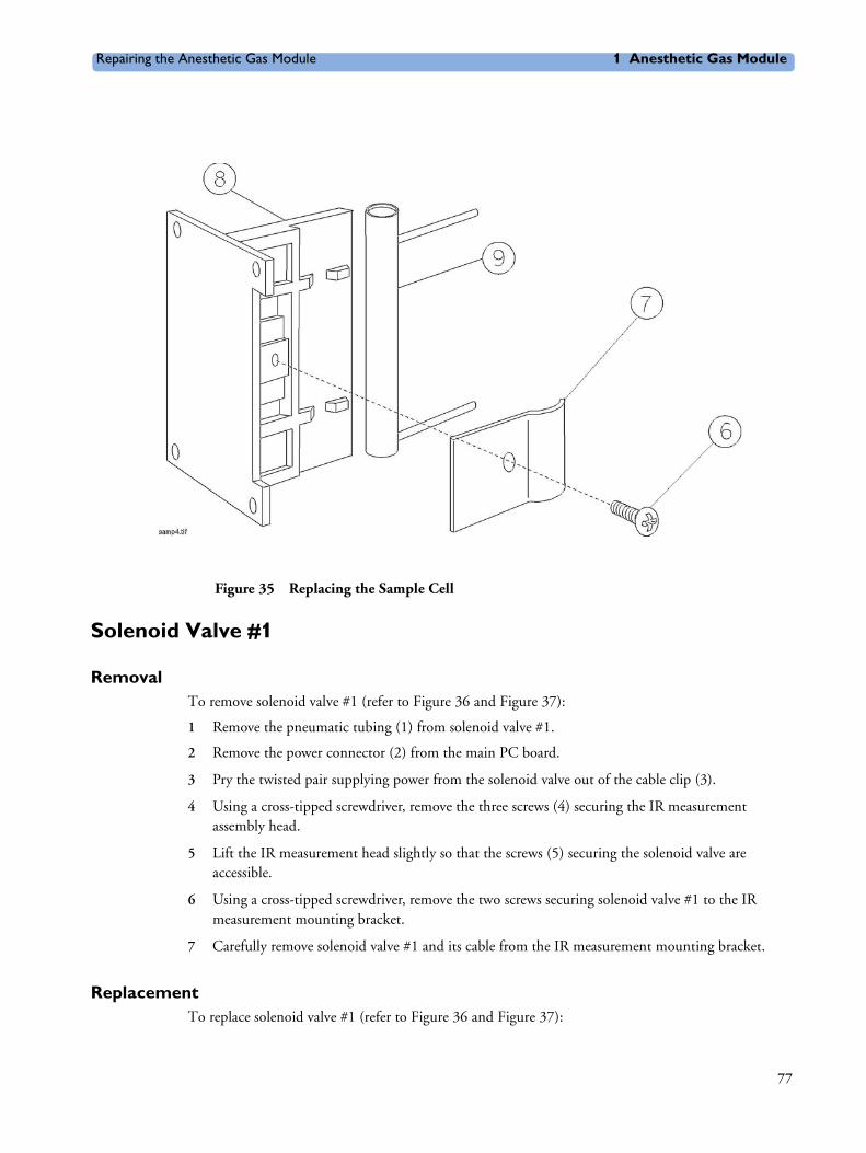
Repairing the Anesthetic Gas Module 1 Anesthetic Gas Module
Figure 35 Replacing the Sample Cell
Solenoid Valve #1
RemovalTo remove solenoid valve #1 (refer to Figure 36 and Figure 37):
1 Remove the pneumatic tubing (1) from solenoid valve #1.
2 Remove the power connector (2) from the main PC board.
3 Pry the twisted pair supplying power from the solenoid valve out of the cable clip (3).
4 Using a cross-tipped screwdriver, remove the three screws (4) securing the IR measurement assembly head.
5 Lift the IR measurement head slightly so that the screws (5) securing the solenoid valve are accessible.
6 Using a cross-tipped screwdriver, remove the two screws securing solenoid valve #1 to the IR measurement mounting bracket.
7 Carefully remove solenoid valve #1 and its cable from the IR measurement mounting bracket.
Replacement To replace solenoid valve #1 (refer to Figure 36 and Figure 37):
77

1 Anesthetic Gas Module Repairing the Anesthetic Gas Module
1 Lift the IR measurement assembly head slightly so that the threaded bores (5) on the mounting bracket for the solenoid valve are accessible.
2 Carefully position Solenoid Valve #1 so that its locating holes align with the threaded bores on the mounting bracket.
3 Using a cross-tipped screwdriver, replace the two screws (5) securing Solenoid Valve #1 to the IR measurement mounting bracket.
4 Snap the twisted pair from the solenoid valve into the cable clip (3) securing the twisted pairs that connect the IR measurement assembly head to the main PC board.
5 Replace the connection (2) to the main PC board.
6 Replace the pneumatic tubing (1) to Solenoid Valve #1.
NOTE Check that all tubing is tightly connected and show no signs of damage.
After replacing Solenoid Valve #1, check that all flat-cable connectors are firmly seated and show no signs of damage.
7 Using a cross-tipped screwdriver, replace the three screws (4) securing the IR measurement assembly head.
8 Replace the IR measurement assembly mounting bracket (refer to “Lifting the IR Measurement Mounting Bracket” on page 66).
Now perform the performance checks described in the “Test and Inspection Matrix” on page 94.
Figure 36 Removing the Solenoid Valve #1
78

Repairing the Anesthetic Gas Module 1 Anesthetic Gas Module
Figure 37 Replacing the Solenoid Valve #1
Power Supply Unit
Removal To remove the power supply unit (refer to Figure 38):
1 Ensure that the module is switched off and isolated from the mains power supply. Remove the top cover of the module.
2 Remove the ac power connector (1) from the power supply unit.
3 Remove the power connector (2) from the main PC board.
4 Using a cross-tipped screwdriver, remove the four screws (3) securing the power supply unit to its mounting.
5 Remove the power supply unit.
Replacement To replace the power supply unit (refer to Figure 38):
1 Ensure that the module is switched off and isolated from the mains power supply.
2 Carefully place the power supply unit so that its locating holes are aligned with the threaded bores in the mounting on the module.
3 Using a cross-tipped screwdriver, replace the four screws (3) securing the power supply unit to its mounting.
4 Connect the power connector (2) to the main PC board.
79

1 Anesthetic Gas Module Repairing the Anesthetic Gas Module
5 Connect the ac power connector (1) to the power supply unit.
6 Replace the top cover of the module.
Now perform the performance checks described in the “Test and Inspection Matrix” on page 94.
Figure 38 Removing and Replacing the Power Supply Unit
Main PC Board
Removal To remove the main PC board (refer to Figure 39):
1 Ensure that the Module is switched off and isolated from the mains power supply. Remove the top cover of the module.
2 Remove the pneumatics tubing from the pressure transducer (1).
3 Remove the main PC board connector (2) from the power supply unit.
4 Remove the power connectors (3) that connect the main PC board to the fan, solenoid valve #1, pump and solenoid valve #2.
5 Remove the flat-cable connector (4) from the IR measurement head.
6 Remove the flat-cable connector (5) from the RS232 connector.
7 Remove the flat-cable connector (6) from the agent identification head.
80

Repairing the Anesthetic Gas Module 1 Anesthetic Gas Module
8 If O2 sensor is present, remove the flat-cable connector (7) from the small O2 sensor PC board (or directly from the O2 sensor, for sensors with integrated PC board).
9 Remove the connector (9) from the power LED.
10 Using a cross-tipped screwdriver, remove the cable clamps (12).
11 Using a cross-tipped screwdriver, remove the 6 screws (10) securing the main PC board to its mounting on the module.
12 Carefully remove the main PC board.
Replacement To replace the main PC board (refer to Figure 39):
1 Ensure that the module is switched off and isolated from the mains power supply.
2 Carefully place the main PC board on its mounting in the Anesthetic Gas Module so that the 6 locating holes are aligned with the threaded bores.
3 Using a cross-tipped screwdriver, replace the 6 screws and washers (10) securing the main PC board to its mounting, and replace the cable clamps.
4 Replace the connector (9) to the power LED.
5 If the O2 sensor is present, replace the flat-cable connector (7) to the O2 sensor PC board (or directly to the O2 sensor). Verify the O2 jumper settings.
6 Replace the flat-cable connector (6) to the agent ID head.
7 Replace the flat-cable connector (5) to the RS232 connector.
8 Replace the flat-cable connector (4) to the IR measurement head.
9 Replace the power connectors (3) that connect the main PC board to the fan, pump, solenoid #1 and solenoid #2.
10 Replace the main PC board connector (2) to the power supply unit.
11 Refit the pneumatic tubing to the pressure transducer (1). Check that all tubing is tightly connected and show no signs of damage.
12 Replace the top-cover cable (8) to the PC board.
NOTE After replacing the main PC board, check that all flat-cable connectors are firmly seated and show no signs of damage.
Verify the O2 jumper settings as described in “Jumpers” on page 60.
Make a flowrate check.
13 Replace the top cover of the module. Ensure that the top cover jumper (JP7) is set to “closed”.
14 Do a configuration check in service mode (Agent-ID, O2 sensor).
Now perform the performance checks described in the “Test and Inspection Matrix” on page 94.
81

1 Anesthetic Gas Module Repairing the Anesthetic Gas Module
Figure 39 Removing the Main PC Board
O2 SensorThe O2 sensor is always replaced together with the small PC board that controls it. The newer O2 sensors have the board integrated inside the sensor housing.
Removal To remove the O2 sensor and its PC board follow the steps marked (a) and to remove the O2 sensor with integrated PC board follow the steps marked (b) (refer to Figure 40 and Figure 41):
1 Ensure that the module is switched off and isolated from the mains power supply. Remove the top cover of the module.
2 Remove the 3 pneumatic connections (1) from the O2 sensor.
3 Remove the flat cable connector (2) from the PC board that controls the O2 sensor.
4 Remove the flat cable connector (2) from the connector on the top of the O2 sensor housing.
5 Release the clips (3) securing the PC board to its mounting.
6 Using a cross-tipped screwdriver, remove the two screws and washers (4) securing the O2 sensor to its mounting brackets.
7 Carefully remove the O2 sensor [(b) along with its PC board.]
82

Repairing the Anesthetic Gas Module 1 Anesthetic Gas Module
NOTE If you are not operating O2, remove the appropriate jumper.
Replacement To replace the O2 sensor and its PC board follow the steps marked (a) and to replace the O2 sensor with integrated PC board follow the steps marked (b) (refer to Figure 40 and Figure 41):
1 Ensure that the module is switched off and isolated from the mains power supply.
2 Carefully place the O2 sensor on its mounting so that the locating holes are aligned with the threaded bores.
3 Press the PC board onto its mounting until it clicks into place, and is firmly secured by the clips (3).
NOTE Make sure that the PC board is inserted so that the smaller connector points toward the main PC board.
1 Place the bracket with the internal bacterial filters (5) onto the mounting bracket, aligning the locating holes.
2 Using a cross-tipped screwdriver, replace the two screws and washers (4) securing the O2 sensor to its mounting.
3 Replace the flat cable connector (2) that connects the main PC board to the PC board that controls the O2 sensor.
4 Replace the flat cable connection (2) to the top of the O2 sensor housing.
NOTE Verify the O2 jumper settings.
5 Replace the 3 pneumatic connections (1) to the O2 sensor. Connect the tubing with the T-piece to the O2 sensor inlets (upper and lower connections). Connect the single tubing to the outlet (middle connection). Check that all tubing is tightly connected and show no signs of damage.
NOTE After replacing the O2 sensor and, where applicable, its controlling PC board, check that all flat-cable connectors are firmly seated and show no signs of damage.
6 Replace the top cover of the module.
Now perform the performance checks described in the “Test and Inspection Matrix” on page 94.
83
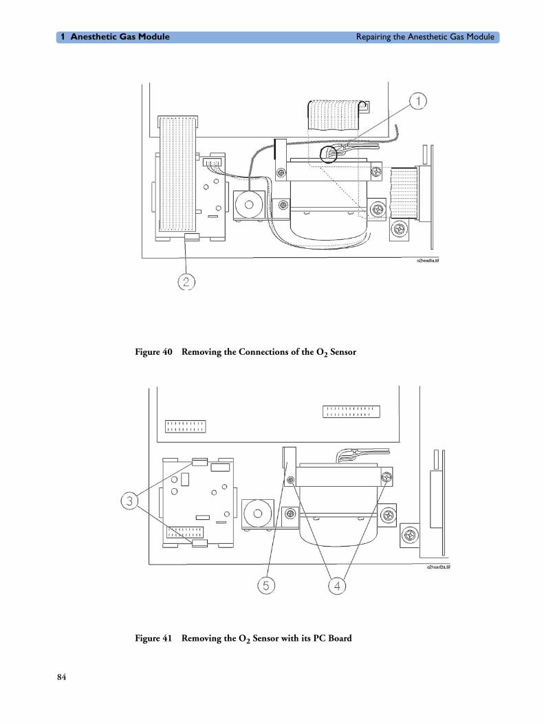
1 Anesthetic Gas Module Repairing the Anesthetic Gas Module
Figure 40 Removing the Connections of the O2 Sensor
Figure 41 Removing the O2 Sensor with its PC Board
84

Repairing the Anesthetic Gas Module 1 Anesthetic Gas Module
Figure 42 Layout showing O2 sensor with Integrated PC Board
Figure 43 Location of Adjustment Potentiometers on O2 Sensor with Integrated PC Board
Agent Identification Head
Removal To remove the agent ID head (refer to Figure 44):
1 Ensure that the module is switched off and isolated from the mains power supply. Remove the top cover of the module.
2 Remove the flat cable connection (1) from the Agent-ID.
3 Remove the 3 pneumatic connections (2) from the side of the agent ID head.
85

1 Anesthetic Gas Module Repairing the Anesthetic Gas Module
4 Using a cross-tipped screwdriver, remove the 4 screws (3) securing the agent ID head to the IR measurement mounting bracket.
5 Carefully remove the agent ID head from the module.
Replacement To replace the agent ID head (refer to Figure 44):
1 Place the agent ID head onto the IR measurement unit so that its threaded bores align with the locating holes provided.
2 Replace the 3 pneumatic connections (2) to the side of the agent ID head. The top and bottom connections are the inlets, and the middle connection is the outlet to the pump. Check that all tubing is tightly connected and show no signs of damage.
3 Using a cross-tipped screwdriver, replace the 4 screws (3) securing the agent ID head to the IR measurement mounting bracket.
4 Replace the flat cable connection (1) to the Agent-ID.
NOTE After replacing the agent ID head, check that all flat-cable connectors are firmly seated and show no signs of damage.
5 Replace the top cover of the module.
Now perform the performance checks described in the “Test and Inspection Matrix” on page 94.
Figure 44 Removing and Replacing the Agent ID Head
86

Repairing the Anesthetic Gas Module 1 Anesthetic Gas Module
Pump
Removal To remove the pump (refer to Figure 45):
1 Ensure that the module is switched off and isolated from the mains power supply. Remove the cover of the module.
2 Remove the pneumatic connections (1) and/or (4) from the pump.
3 Remove the power connection from the main PC board (2).
4 Using a cross-tipped screwdriver, remove the two screws and washers (3) securing the pump to the IR measurement mounting bracket.
5 Carefully slide out the pump from the IR measurement mounting bracket.
Replacement To replace the pump (refer to Figure 45):
1 Carefully position the pump so that the threaded bores in the pump align with the locating holes on the IR measurement mounting bracket.
2 Using a cross-tipped screwdriver, replace the two screws and washers (3) securing the pump to the IR measurement mounting bracket.
3 Replace the connection (2) to the main PC board (to the dc pump connector).
4 Replace the pneumatic connections (1) and/or (4) to the pump. Check that all tubing is tightly connected and show no signs of damage.
NOTE After replacing the pump, check that all flat-cable connectors are firmly seated and show no signs of damage.
5 Replace the top cover of the module.
Now perform the performance checks described in the “Test and Inspection Matrix” on page 94 and reset the pump hours.
To reset pump hours, select Reset Pump Hours from the Setup Gas Analyzer menu in the monitor’s service mode. Confirm when prompted.
87

1 Anesthetic Gas Module Repairing the Anesthetic Gas Module
Figure 45 Replacing the Pump
Fan
Removal To remove the fan (refer to Figure 46 and Figure 47):
1 Ensure that the Anesthetic Gas Module is switched off and isolated from the mains power supply. Remove the top cover of the module.
2 Remove the power connector (1) from the main PC board.
3 Pry the twisted pair supplying power from the fan out of the cable clip (2).
4 Using a cross-tipped screwdriver, remove the four screws and washers (3) securing the fan and the grill to the back panel of the module.
5 Remove the fan and connecting cable from the module.
Replacement To replace the fan (refer to Figure 46 and Figure 47):
1 Ensure that the Module is switched off and isolated from the mains power supply.Replace the fan and connecting cable.
2 Replace the four screws and washers (3) that secure the fan into the back panel of the module.
88

Repairing the Anesthetic Gas Module 1 Anesthetic Gas Module
3 Snap the twisted pair from the fan into the cable clip (2) securing the twisted pairs that connect the IR measurement head with the main PC board.
4 Replace the connector (1) to the main PC board.
5 Replace the top cover of the module.
Now perform the performance checks described in the “Test and Inspection Matrix” on page 94.
Figure 46 Removing the Fan Cabling
89
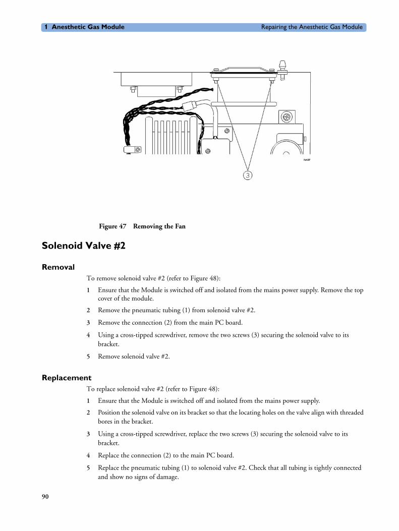
1 Anesthetic Gas Module Repairing the Anesthetic Gas Module
Figure 47 Removing the Fan
Solenoid Valve #2
Removal To remove solenoid valve #2 (refer to Figure 48):
1 Ensure that the Module is switched off and isolated from the mains power supply. Remove the top cover of the module.
2 Remove the pneumatic tubing (1) from solenoid valve #2.
3 Remove the connection (2) from the main PC board.
4 Using a cross-tipped screwdriver, remove the two screws (3) securing the solenoid valve to its bracket.
5 Remove solenoid valve #2.
Replacement To replace solenoid valve #2 (refer to Figure 48):
1 Ensure that the Module is switched off and isolated from the mains power supply.
2 Position the solenoid valve on its bracket so that the locating holes on the valve align with threaded bores in the bracket.
3 Using a cross-tipped screwdriver, replace the two screws (3) securing the solenoid valve to its bracket.
4 Replace the connection (2) to the main PC board.
5 Replace the pneumatic tubing (1) to solenoid valve #2. Check that all tubing is tightly connected and show no signs of damage.
90

Repairing the Anesthetic Gas Module 1 Anesthetic Gas Module
NOTE After replacing solenoid valve #2, check that all flat-cable connectors are firmly seated and show no signs of damage.
6 Replace the top cover of the module.
Now perform the performance checks described “Test and Inspection Matrix” on page 94.
Figure 48 Removing the Solenoid Valve #2
Top Cover PC Board
Removal To remove the top cover PC board (refer to Figure 49 and Figure 50):
1 Ensure that the Module is switched off and isolated from the mains power supply. Remove the top cover of the module.
2 Remove the connector (1) from the top cover PC board.
3 Using a hex-socket screwdriver, remove the three nuts, washers and spacers (2) securing the PC board to the top cover of the module.
4 Remove the PC board.
Replacement To replace the top cover PC board (refer to Figure 49 and Figure 50):
1 Ensure that the Module is switched off and isolated from the mains power.
91

1 Anesthetic Gas Module Repairing the Anesthetic Gas Module
2 Carefully fit the PC board over the three locating screws on the top cover of the module.
3 Using a hex-socket screwdriver, replace the three nuts, washers and spacers (2) securing the PC board to the top cover.
4 Replace the connector (1) to the top cover PC board.
5 Replace the top cover of the module.
Now perform the performance checks described “Test and Inspection Matrix” on page 94.
Figure 49 Removing the Top Cover PC Board Connection
Figure 50 Removing the Top Cover PC Board
92

Repairing the Anesthetic Gas Module 1 Anesthetic Gas Module
Watertrap Manifold and Protector
RemovalTo remove the manifold and protector (refer to Figure 51):
1 Remove the top cover of the module.
2 Remove the Nafion tubing and purple connector tubing from the manifold connectors (1) on the inside of the front cover.
3 Using a cross-tipped screwdriver, unscrew the 4 screws (2) securing the protector to the front cover and remove the protector.
4 Using a cross-tipped screwdriver, unscrew the 2 screws (3) securing the manifold to the protector.
ReplacementTo replace the manifold and protector (refer to Figure 51):
1 Using a cross-tipped screwdriver, replace the 2 screws securing the manifold to the protector.
2 Using a cross-tipped screwdriver, replace the 4 screws securing the protector to the front cover.
3 Replace the Nafion tubing and purple connector tubing onto the manifold connectors on the inside of the front cover. Take care to attach the tubing with the red mark at the end to the connector with the red marking (this indicates the “drainage” path). The gap between the end of the nafion tubing and the manifold connectors (visible through the purple connector tubing) must be less than 1mm.
Now perform the performance checks described “Test and Inspection Matrix” on page 94.
Figure 51 Removing the Watertrap Manifold and Protector
93

1 Anesthetic Gas Module Repairing the Anesthetic Gas Module
Power Fuses
RemovalTo remove the power fuses (refer to Figure 52):
1 Using a flat-tipped screwdriver, unscrew the fuse counter-clockwise (1).
2 Pull the fuse cap and fuse clear of the display.
3 Pull the fuse out of the fuse cap and note the fuse rating.
4 Repeat the steps for the other fuse.
ReplacementTo replace the power fuses (refer to Figure 52):
1 Put one end of the fuse into the fuse cap.
2 Put the fuse and fuse cap into the receptacle in the rear of the display.
3 Using a flat-tipped screwdriver, screw the fuse clockwise into the receptacle.
4 Repeat the steps for the other fuse.
Figure 52 The Power Fuses
Test and Inspection MatrixThe Test and Inspection Matrix describes:
• which tests need to be performed
• the expected test results
• what should be written by Philips service personnel on the Philips Installation Report or Customer Service Order (CSO).
The second section When to Perform Test Blocks describes when the tests should be performed.
94

Repairing the Anesthetic Gas Module 1 Anesthetic Gas Module
These tables should be followed for all installations and repairs.
NOTE The test procedures outlined for this test block are to be used only for verifying safe installation or service of the product in question. The setups for these tests and the acceptable ranges or values are derived from local and international standards but may not be equivalent. These are not a substitute for local safety testing where it is required for an installation or service event.
Test Block Name Test or Inspection to be performed Expected Test Result What to Record on Service Record
Visual Check for any mechanical damage and all external leads and accessories. Is the device free of damage and are all accessories properly set up?
Expected answer is "yes".
If so, visual test is passed.
V: P or
V: F
where P=Pass and F=Fail
Power On Switch on the module. A built-in selftest and communication test are running for two minutes after "Power On". The green setup LED near the power button indicates by flashing if one of the tests failed. When tests are successfully completed after 2 minutes the LED is off and the AGM will enter warmup mode (indicated by INOP "GA.WARMUP").
Does AGM boot up successfully without displaying any error or malfunction messages?
Expected answer is "yes". If so, PowerOn test is passed.
PO: P or
PO: F
where P=Pass and F=Fail
Performance Leakage Check
Perform Leakage Check Measured flow value: 0-4 ml/min
PL: P or
PL: F
where P=Pass and F=Fail
Performance Flowrate Check
Perform Flowrate Check. Document the actual flowrates.
Flowrates M1026A #A02/#A05:
Purge = x1 (310 +/- 15 ml/min)
Measurement Path = x2 (labelled value +/- 3 ml/min)
Normal = x3 (132 - 170 ml/min)
PF: P/x1/x2/x3 or
PF: F/x1/x2/x3
where P=Pass and F=Fail
95

1 Anesthetic Gas Module Repairing the Anesthetic Gas Module
Performance Diagnostic Check
Perform the Diagnostic/Error Check.
Does the status of each subassembly display as "OK" in Gas Analyzer Diagnostic window?
The subassemblies are:
- Meas. Assembly
- Meas. Opt. Path
- Agent-ID
- O2 Assembly
- Main PCB
- Power Supply
- Pneumatic System
- Operat. Temperature
Expected answer is "yes".
If so, Error/Diagnostic check is passed.
PD:P or
PD:F
where P=Pass and F=Fail
Performance Zero Calibration Check
Does the status of each channel display as "OK" in the Gas Analyzer Calibration window after zero calibration?
The channels are:
- Press
- O2
- CO2
- N2O
- Subst.
Expected answer is "yes".
If so, zero calibration check is passed.
PZC:P or
PZC:F
where P=Pass and F=Fail
Performance Barometric Pressure Check
Perform Barometric Pressure Check . Difference between actual measured pressure value and actual ambient pressure value = x (<= 5 mmHg)
PBP:P/x or
PBP:F/x
where P=Pass and F=Fail
Test Block Name Test or Inspection to be performed Expected Test Result What to Record on Service Record
96

Repairing the Anesthetic Gas Module 1 Anesthetic Gas Module
Performance Span Calibration Check
Perform the Span Calibration Check.
Document the actual measured values for each gas channel.
If failed (out of specified tolerances) - perform a span calibration for specific gas channel.
O2 value = x1 (+- 1.0% to O2 calibration value )
CO2 value = x2 (+- 0.1% to CO2 calibration value)
N2O value = x3 (+- 2.0% to N2O calibration value))
Agent value = x4 (+- 0.1% to Agent value)
When calibration of EACH gas channel was necessary, status of each channel shows "Done".
Result to report in this case is PSH:P (without individual gas value results)
PSH:P/x1/x2/x3/x4 or
PSH:F/x1/x2/x3/x4
where P=Pass and F=Fail
alternatively
PSH:P or
PSH:F
where P=Pass and F=Fail
Performance Normal Operation Check
Enter Monitoring mode and check that all AGM related waves and numerics are present and correspond to the user’s configuration.
Are all AGM waves and numerics present according to the user’s configuration?
Expected answer is "yes". If so, performance normal operation check is passed.
PNO: P or
PNO: F
where P=Pass and F=Fail
Performance Pump Test
Using the pump test kit provided in the PM kit, clean and test the pump according to the included instructions. Did the pump pass the test?
Expected answer is "yes".
If so, test is passed.
PPU: P or
PPU: F
where P=Pass and F=Fail
Performance Fan Check
Check that the cooling fan runs smoothly.
Did the fan pass the test?
Expected answer is "yes".
If so, fan check is passed.
PFA: P or
PFA: F
where P=Pass and F=Fail
Test Block Name Test or Inspection to be performed Expected Test Result What to Record on Service Record
97
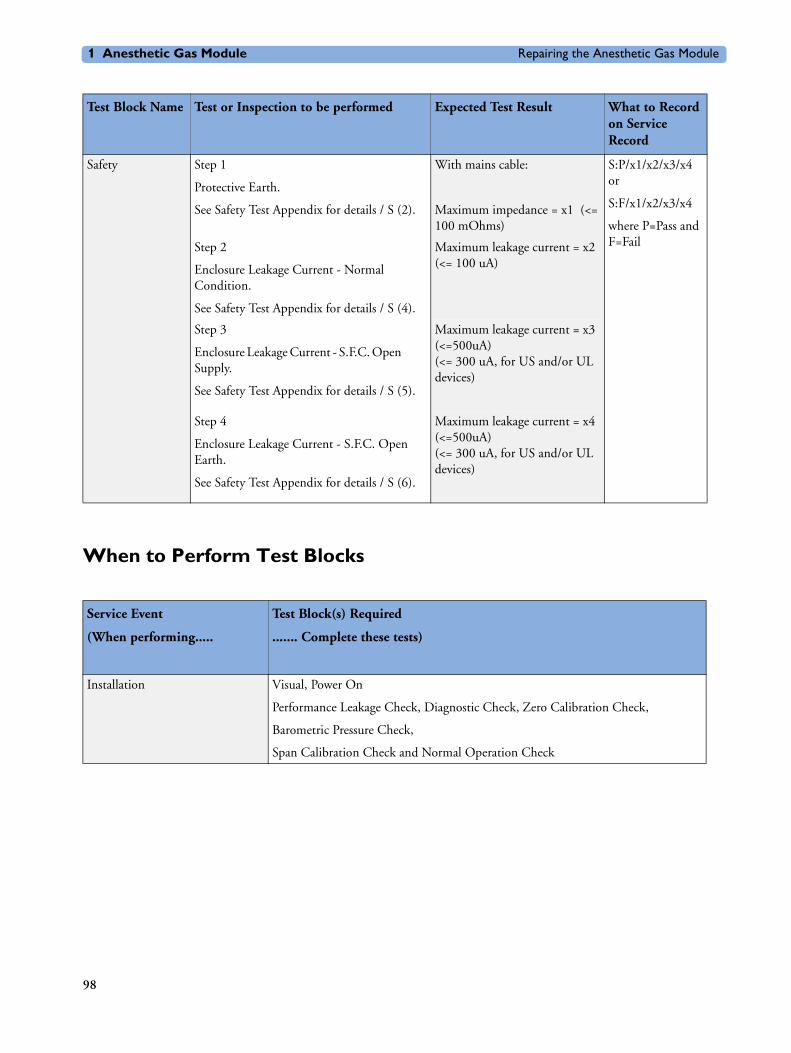
1 Anesthetic Gas Module Repairing the Anesthetic Gas Module
When to Perform Test Blocks
Safety Step 1
Protective Earth.
See Safety Test Appendix for details / S (2).
With mains cable:
Maximum impedance = x1 (<= 100 mOhms)
S:P/x1/x2/x3/x4 or
S:F/x1/x2/x3/x4
where P=Pass and F=FailStep 2
Enclosure Leakage Current - Normal Condition.
See Safety Test Appendix for details / S (4).
Maximum leakage current = x2 (<= 100 uA)
Step 3
Enclosure Leakage Current - S.F.C. Open Supply.
See Safety Test Appendix for details / S (5).
Maximum leakage current = x3 (<=500uA)(<= 300 uA, for US and/or UL devices)
Step 4
Enclosure Leakage Current - S.F.C. Open Earth.
See Safety Test Appendix for details / S (6).
Maximum leakage current = x4 (<=500uA)(<= 300 uA, for US and/or UL devices)
Test Block Name Test or Inspection to be performed Expected Test Result What to Record on Service Record
Service Event
(When performing.....
Test Block(s) Required
....... Complete these tests)
Installation Visual, Power On
Performance Leakage Check, Diagnostic Check, Zero Calibration Check,
Barometric Pressure Check,
Span Calibration Check and Normal Operation Check
98

Repairing the Anesthetic Gas Module 1 Anesthetic Gas Module
Safety Test AppendixThe test procedures outlined in this appendix are to be used only for verifying safe installation or service of the product in question.
The setups used for these tests and the acceptable ranges of values are derived from local and international standards but may not be equivalent.
These tests are not a substitute for local safety testing where it is required for an installation or a service event.
If using the Metron Safety tester use your local regulation to perform the test, for example in Europe IEC60601-1/IEC60601-1-1 and in the US UL2601-1. The Metron Report should print results with the names listed below, along with other data.
"Safety checks at installation refer to safety aspects directly related to the installaton and setup activities and not to intrinsic safety features that have already been checked during final acceptance testing at the factory".
Repair/Parts replacement Performance Leakage Check, Flowrate Check, Diagnostic Check,
Zero Calibration Check, Barometric Pressure Check,
Span Calibration Check and Normal Operation Check,
Safety (whenever the topcover was opened)
Preventive Maintenance Parts Replacement as described in Chapter 5 of
the Anesthetic Gas Module Service Manual (part number M1026-9000B).
Fan Check, Pump Test, Performance Leakage Check, Flowrate Check,
Diagnostic Check, Zero Calibration Check, Barometric Pressure Check,
Span Calibration Check and Normal Operation Check, Safety
Service Event
(When performing.....
Test Block(s) Required
....... Complete these tests)
99

1 Anesthetic Gas Module Repairing the Anesthetic Gas Module
Test Block name Test or Inspection to perform
S(2)
Protective Earth
Measures impedance of Protective Earth (PE) terminal to all exposed metal parts of Instrument under Test (IUT), which are for safety reasons connected to the Protective Earth (PE). Includes normally the wiring in the mains cable (max. 100 mOhm). Test current 25 Amps applied for 5 seconds to 10 seconds. The recommendation is to flex the main cable during the test in order to identify potential bad contact or damage of the earth wire.
Safety test according IEC 60601-1 (Clause 18) Report largest value.
S(4) Test ENCL.1:
Enclosure Leakage Current - NC (normal condition)
Applicable to Class 1 & 2 equipment, type B, BF & CF Applied Parts.Measures leakage current of exposed metal parts of UIT; normal and reversed polarity using S2.
For type BF & CF Applied Parts measures with AP/GND switch S3 open and closed.
Safety test according to IEC 60601-1 (Clause 19.4g) Report largest value.
100

Parts List 1 Anesthetic Gas Module
Parts ListThis chapter provides the replacement and exchange part numbers (if available) for the Philips M1026A Anesthetic Gas Module and calibration equipment. Refer to Figure 53 and the following table to identify the part and part number.
S(5)
Enclosure Leakage Current – Single Fault Condition Open Supply
Applicable to Class 1 & 2 equipment, type B, BF & CF Applied Parts.Measures leakage current of exposed metal parts of IUT with one supply lead interrupted (S1=open); normal and & reversed polarity using S2. For type BF a& CF Applied Parts measures with AP/GND switch S3 open and closed.
Safety test according to IEC 60601-1 (Clause 19.4g)Report largest value.
S(6) Enclosure Leakage Current - Single Fault Condition Open Earth (Ground)
Applicable to Class 1 equipment, type B, BF, & CF Applied Parts. Measures leakage current of exposed metal parts of UIT with Protective Earth open-circuit (S4=open); normal & reversed polarity using S2. For type BF & CF Applied Parts measures with with AP/GND switch S3 open and closed.
Safety test according to IEC 60601-1 (Clause 19.4g) Report largest value.
Test Block name Test or Inspection to perform
101

1 Anesthetic Gas Module Parts List
The circuit boards used in the Anesthetic Gas Module contain Surface Mounted Devices (SMD) which can only be repaired with special equipment, not available in the field. For this reason, the majority of the parts used in the system can only be replaced at board level.
Table legend:
R Replacement Part
E Exchange Part
Std.A-ID Standard Agent Identification
Ext.A-ID Extended Agent Identification
102

Parts List 1 Anesthetic Gas Module
Figure 53 Replacement Parts
103

1 Anesthetic Gas Module Parts List
Part Number Description R/E
M1026-60100 Power Supply, 2 output, 3A, 120mA R
M1026-60330 Pump Assy. R
M1026-60102 Solenoid Valve Assy. R
M1026-60503 Main PCB (fully loaded) for 5 Agent-ID R
M1026-69503 Main PCB (fully loaded) for 5 Agent-ID E
M1026-60105 Front Panel PCB R
M1026-60106 Fan, 12Vdc R
M1026-60510 M1026A 5 Agent Identification (A-ID) R
M1026-69510 M1026A 5 Agent Identification (A-ID) E
M1026-60138 Oxygen Sensor Assy. w/ integrated pcb R
M1026-69138 Oxygen Sensor Assy. w/ integrated pcb E
M1026-60112 Sample Cell R
M1026-60135 Top cover R
M1026-60108 IR Assembly Kit R
M1026-69108 IR Assembly Kit E
M1026-01200 Retrofit Clip R
M1026-60146 Manifold Seals R
Part Number of Kit Description
M1026-60132 Preventive Maintenance Kit. Includes:
Nafion tubing with internal bacterial filters
Room air filter
Pump outlet filter
Pump test tubing
Watertrap manifold seals
M1026-60117 Gas Inlet/Outlet Kit. Includes:
Barb
Retainer
Nut
Fitting 1/8 in. ID (4mm), Female inline coupling
Fitting with nut, Panel Mount, Male coupling (2 pieces)
104

Parts List 1 Anesthetic Gas Module
M1026-60119 Tubing Kit. Includes:
Tubing 1/8 in. ID x 3/16 in. OD (1 ft.)
Tubing 1/32 in. ID x 3/32 in. OD (5 ft.)
Tubing 039 in. ID x 120 in. OD (5 ft.)
Tubing 060 in. ID x 187 in. OD (5 ft.)
Tubing 1.14 mm ID x 1.57 mm OD (5 ft.)
Tube fitting, Tee for 1/16 in. tubing (Qty=2 per AGM)
Tube fitting, Tee for 1/16 in. ID & 1/8 in. ID tubing (Qty=1 per AGM)
Pulse dampener kit, with T-fitting
Flow-control tubing assembly
Flow restriction kit
M1026-60120 Power Button Kit (5 pieces). Includes:
Power button
Power button switch
Coupler, power switch
Shaft, short, power switch
Pushrod, power switch
M1026-60121 Power Module Kit. Includes:
Filter, Power Line, 1.5A, 250V
Assy. Daisy chain power
Assy. Power entry module
Assy. Harness, AC power-filtered
Assy. Harness, AC power unfiltered, black
Assy. Harness, AC power unfiltered, white
M1026-60122 Cable Kit (6 pieces). Includes:
Cable, Assy. 9 pin (power supply to PCB)
Cable, Assy. Flat. 40 pin (4710 head to PCB)
Cable, Assy. Flat, 26 pin (4740 head to PCB)
Cable, Assy. Flat, DB25 to 26 pin (RS232/ PCB)
Cable, Assy. Flat, 16 pin (O2 PCB to PCB)
Cable, Assy, 2 pin with LED
M1026-60123 Rubber Spacer Kit
M1026-60127 Main EPROM
M1026-60133 WT Manifold kit
M1026-60134 WT Protector kit
M1026-60136 Flow Split Test Kit
2110-0495CP Fuses
Part Number of Kit Description
105

1 Anesthetic Gas Module Parts List
Calibration Equipment The following table lists the part numbers for the calibration equipment.
Part Number Description
M1026-60144 Electronic Flow meter
M1657B Watertrap
M1658A Sample Tubing
M1659A Calibration Tube Assembly
M1660A1
1.This Calibration Gas Assembly cannot be ordered in Japan; use Scott Medical Products DOT29M1060 instead.
Calibration Gas Assembly(3% Halocarbon 22, 5% CO2, 40% N2O, 52% O2)
Previous part number New part number Effective Date
M1026-60101 Pump assy., square-shaped
M1026-60130 Pump assy., round-shaped
August 1997
M1026-60111 Oxygen Sensor assy. with PC board separate
M1026-60138 Oxygen Sensor assy. with PC board integrated in housing
June 1998
M1026-60110 Ext.Agent-ID M1026-60210 Ext. Agent-ID October 1998
M1026-60130 Pump Kit M1026-60230 Pump Kit June 1999
M1026-60230 Pump Kit M1026-60330 Pump Kit April 2000
106

A
agent ID assemblyoverview 13removal and replacement 85
alarm limit ranges 7
altitude configuration 20
Anesthetic Gas Exhaust 18
Anesthetic Gas Modulealarm limit ranges 7CO2 measurement specifications 7environmental specifications 6general description 5general measurement principles 9INOP alarms 8introduction 5physical specifications 5repairing 62theory of operation 9
B
bacterial filterpart numbers 106
C
calibrationchecks 48equipment part numbers 106gas regulator part numbers 106O2 Zero calibration 49Span calibration 32, 50tube assembly part numbers 106
cleaning 36
CO2measurement specifications 7
combining equipment (installation) 23
configurationaltitude 20
connecting the AGM 17
connectors 60
D
diagnostic checks 50
E
environment 17
equipotential grounding 23
F
factory defaultsrestoring 48
fan removal and replacement 88
flow meterpart numbers 106
275
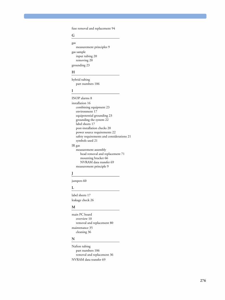
fuse removal and replacement 94
G
gasmeasurement principles 9
gas sampleinput tubing 20removing 20
grounding 23
H
hybrid tubingpart numbers 106
I
INOP alarms 8
installation 16combining equipment 23environment 17equipotential grounding 23grounding the system 22label sheets 17post-installation checks 20power source requirements 22safety requirements and considerations 21symbols used 21
IR gasmeasurement assembly
head removal and replacement 71mounting bracket 66NVRAM data transfer 69
measurement principle 9
J
jumpers 60
L
label sheets 17
leakage check 26
M
main PC boardoverview 10removal and replacement 80
maintenance 35cleaning 36
N
Nafion tubingpart numbers 106removal and replacement 36
NVRAM data transfer 69
276

O
O2Span calibration 50Span calibration checks. 50Zero calibration checks 49
O2 sensor assemblyremoval and replacement 82
P
part numbers 101
performanceleakage check 26
pneumatic systemoverview 11
power supplyfuses removal and replacement 94overview 11requirements 22unit removal and replacement 79
pre-use checks 20
preventive maintenance 35tasks 20
pumpfilter removal and replacement 39removal and replacement 87
R
rear panel connectors 17
repairingagent ID head 85fan 88fuses 94introduction 62IR measurement assembly head 71IR measurement mounting bracket 66main PC board 80Nafion tubing 36O2 sensor 82power supply unit 79pump 87pump filter 39room-air filter 38sample cell 73sample line 36solenoid valve #1 77solenoid valve #2 90top cover 64top cover PC board 91
return the gas sample 18
room-air filter removal and replacement 38
S
safety 16requirements and considerations 21
277

sample cellremoval and replacement 73
sample linepart numbers 106removal and replacement 36
setup for Gas Exhaust Return line 19
solenoid valveremoval and replacement
#1 77#2 90
Span calibration 32
symbol explanations 21
T
test points 59
theory of operation 9
top coverPC board removal and replacement 91removal and replacement 64
troubleshootingcalibration checks 48diagnostic checks 50
tubingremoval and replacement 36
W
watertrap manifiold protectorremoval and replacement 93
278