Service Manual - Frank's Hospital...
52
Le marquage CE qui se trouve sur ce produit indique que celui-ci est en conformité avec la directive européenne des dispositifs médicaux 93/42/CEE This product bears a CE marking in accordance with the provisions of the 93/42/EEC MDD dated June 14, 1993. 0459 Technical Publication SM-0521R3 Service Manual BRS Basic Radiographic System STEPHANIX rue Jean Moulin Zone Industrielle du Bayon 42150 La Ricamarie FRANCE Tel. : 00 33 4 77 47 81 60 ; Fax : 00 33 4 77 37 55 19
-
Upload
duongnguyet -
Category
Documents
-
view
232 -
download
0
Transcript of Service Manual - Frank's Hospital...
Le marquage CE qui se trouve sur ce produit indique que celui-ci est en conformité avec la directive européenne des dispositifs médicaux 93/42/CEEThis product bears a CE marking in accordance with the provisions of the 93/42/EEC MDD dated June 14, 1993.0459
Technical PublicationSM-0521R3
Service Manual
BRSBasic Radiographic System
STEPHANIX
rue Jean Moulin
Zone Industrielle du Bayon
42150 La Ricamarie
FRANCE
Tel. : 00 33 4 77 47 81 60 ; Fax : 00 33 4 77 37 55 19

Basic Radiographic System
Service Manual
SM-0521R3
REVISION HISTORY
REVISION DATE REASON FOR CHANGE
0 April 22, 2003 First edition
1 30 March, 2004 Installation and dimensions modified.
2 07 May, 2005 Installation improvements.
3 12 Jul, 2005 New schematics and updated photos.
This Document is the English original version, edited and supplied by the manufacturer.
The Revision state of this Document is indicated in the code number shown at the bottom of this page.
ADVISORY SYMBOLS
The following advisory symbols will be used throughout this manual. Theirapplication and meaning are described below.
DANGERS ADVISE OF CONDITIONS OR SITUATIONS THATIF NOT HEEDED OR AVOIDED WILL CAUSE SERIOUSPERSONAL INJURY OR DEATH.
ADVISE OF CONDITIONS OR SITUATIONS THAT IF NOTHEEDEDORAVOIDEDCOULDCAUSESERIOUSPERSONALINJURY, OR CATASTROPHIC DAMAGE OF EQUIPMENT ORDATA.
Advise of conditions or situations that if not heeded oravoidedcould causepersonal injury or damage to equipmentor data.
Note . Alert readers to pertinent facts and conditions. Notes representinformation that is important to know but which do not necessarilyrelate to possible injury or damage to equipment.
Basic Radiographic System
Service Manual
SM-0521R3
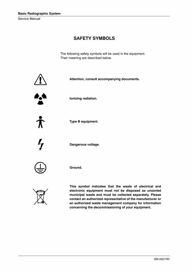
SAFETY SYMBOLS
The following safety symbols will be used in the equipment.Their meaning are described below.
Attention, consult accompanying documents.
Ionizing radiation.
Type B equipment.
Dangerous voltage.
Ground.
This symbol indicates that the waste of electrical andelectronic equipment must not be disposed as unsortedmunicipal waste and must be collected separately. Pleasecontact an authorized representative of the manufacturer oran authorized waste management company for informationconcerning the decommissioning of your equipment.
Basic Radiographic System
Service Manual
SM-0521R3 i
TABLE OF CONTENTS
Section Page
1 INTRODUCTION 1. . . . . . . . . . . . . . . . . . . . . . . . . . . . . . . . . . . . . . . . . . . . . . . . . . . . . . . . .
1.1 Tools 1. . . . . . . . . . . . . . . . . . . . . . . . . . . . . . . . . . . . . . . . . . . . . . . . . . . . . . . . . . . . . .
1.2 Pre-Installation Checks 1. . . . . . . . . . . . . . . . . . . . . . . . . . . . . . . . . . . . . . . . . . . . . .
2 UNPACKING 3. . . . . . . . . . . . . . . . . . . . . . . . . . . . . . . . . . . . . . . . . . . . . . . . . . . . . . . . . . . .
3 INSTALLATION 5. . . . . . . . . . . . . . . . . . . . . . . . . . . . . . . . . . . . . . . . . . . . . . . . . . . . . . . . . .
1.2 Positioner Installation overview 5. . . . . . . . . . . . . . . . . . . . . . . . . . . . . . . . . . . . . . .
4 ADJUSTMENTS 15. . . . . . . . . . . . . . . . . . . . . . . . . . . . . . . . . . . . . . . . . . . . . . . . . . . . . . . .
4.1 Adjustment tools 15. . . . . . . . . . . . . . . . . . . . . . . . . . . . . . . . . . . . . . . . . . . . . . . . . . . .
4.2 Alignment of X-ray Beam 18. . . . . . . . . . . . . . . . . . . . . . . . . . . . . . . . . . . . . . . . . . . .
4.2.1 Alignment of Light Field with X-ray Field 22. . . . . . . . . . . . . . . . . . . . . . . . .
4.2.2 Perpendicularity Adjustment of X-ray Beam with Image Receptor 25. . .
4.2.3 Centering of X-ray Field and Image Receptor Bucky Assembly 27. . . . .
4.3 Field Size Indicator Test 28. . . . . . . . . . . . . . . . . . . . . . . . . . . . . . . . . . . . . . . . . . . . .
4.4 X-ray Tube or Collimator Replacement 30. . . . . . . . . . . . . . . . . . . . . . . . . . . . . . . . .
4.5 Adjustment of rotation Plate 30. . . . . . . . . . . . . . . . . . . . . . . . . . . . . . . . . . . . . . . . . .
5 RENEWAL PARTS 31. . . . . . . . . . . . . . . . . . . . . . . . . . . . . . . . . . . . . . . . . . . . . . . . . . . . . .
6 MANTEINANCE 33. . . . . . . . . . . . . . . . . . . . . . . . . . . . . . . . . . . . . . . . . . . . . . . . . . . . . . . . .
7 INTERCONNECTION MAPS 35. . . . . . . . . . . . . . . . . . . . . . . . . . . . . . . . . . . . . . . . . . . . . .

Basic Radiographic System
Service Manual
SM-0521R3ii

Basic Radiographic System
Service Manual
SM-0521R3 1
SECTION 1 INTRODUCTION
1.1 TOOLS
The following hand tools are required for the Installation:
• Standard service engineers tool kit.
• Electric drill motor and assorted bits.
1.2 PRE-INSTALLATION CHECKS
Prior to beginning installation it is recommended to inspect the site and verifythat the X-ray room complies with requirements such as:
• Themaximum dimensions and systemmovements to plan theminimumspace required in the room:
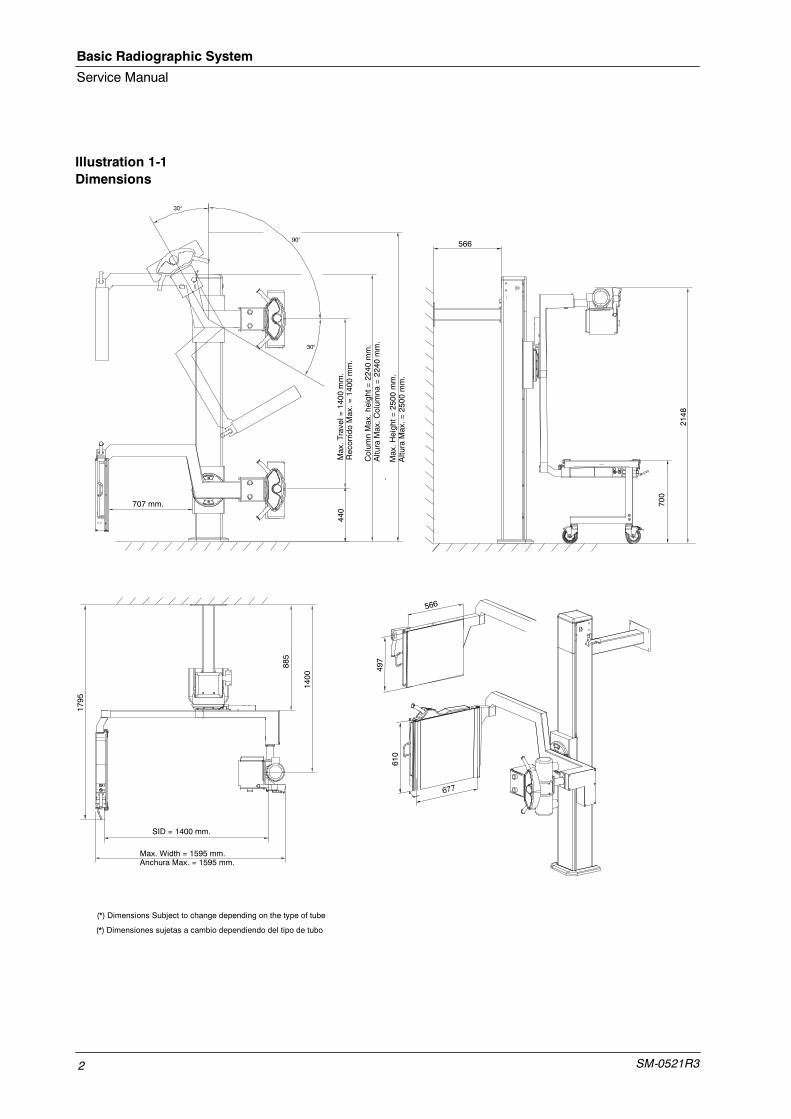
Maximum Height 2500 mm
Maximum Width 1550 mm
Maximum Length 1340 mm
• Conduits and walls are ready to install the System.
• Electricity installation:
Power Line (for Collimator Lamp): 24 VAC, 50/60 Hz, 6.5 A
Power Line (for Movement Locks): 24 VDC, 0.2 kVA
ACCORDING TO MDD93/42/CEE, THIS UNIT IS EQUIPPEDWITH EMC FILTERS. THE LACK OF THE PROPERGROUNDING MAY PRODUCE ELECTRICAL SHOCK TO THEUSER.
Basic Radiographic System
Service Manual
SM-0521R32
Illustration 1-1Dimensions
Max.H
eight=
2500
mm.
AlturaMax.=
2500
mm.
Max.Travel=
1400
mm.
RecorridoMax.=
1400
mm.
Colum
nMax.height=
2240
mm.
AlturaMax.C
olum
na=2240
mm.
700
707 mm.
2148
566
885
1400
SID = 1400 mm.
Max. Width = 1595 mm.Anchura Max. = 1595 mm.
(*) Dimensions Subject to change depending on the type of tube
(*) Dimensiones sujetas a cambio dependiendo del tipo de tubo
1795
440
610
497

Basic Radiographic System
Service Manual
SM-0521R3 3
SECTION 2 UNPACKING
The Unit is shipped in one box to facilitate transport and installation. Uponreceipt of the X-ray unit and associated equipment, inspect all shippingcontainers for signs of damage. If damage is found, notify the carrier or hisagent immediately.
1. Place the shipping pallet near its final site in the room and remove all itslaterals. Do not discard any packing material such as envelopes, boxes,bags until all parts are accounted for as listed on the packing list.
AT LEAST THREE PEOPLE ARE REQUIRED TO REMOVEALL HEAVY COMPONENTS FROM THE SHIPPING PALLET.
2. When the equipment is unpacked, check part numbers and serialnumbers of each component with its identification labels. Inspect allpieces for visible damages. If any damaged part is found, repair it ororder its replacement to prevent unnecessary delay in installation.
3. Verify that all items on the customer order are present.
4. Leave a working area around equipment until its final installation iscomplete.

Basic Radiographic System
Service Manual
SM-0521R34
This page intentionally left blank.
Basic Radiographic System
Service Manual
SM-0521R3 5
SECTION 3 INSTALLATION
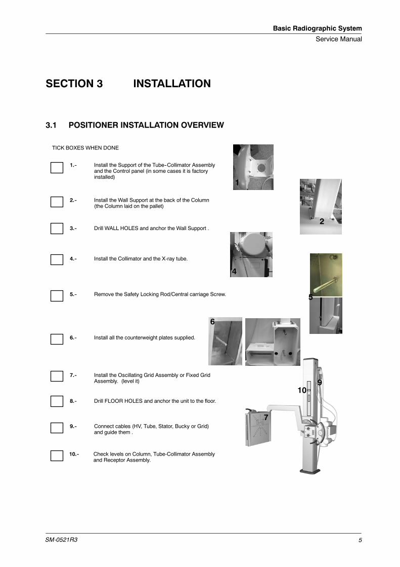
3.1 POSITIONER INSTALLATION OVERVIEW
2.-- Install the Wall Support at the back of the Column(the Column laid on the pallet)
1.-- Install the Support of the Tube--Collimator Assemblyand the Control panel (in some cases it is factoryinstalled)
3.-- Drill WALL HOLES and anchor the Wall Support .
4.-- Install the Collimator and the X-ray tube.
5.-- Remove the Safety Locking Rod/Central carriage Screw.
7.-- Install the Oscillating Grid Assembly or Fixed GridAssembly. (level it)
9.-- Connect cables (HV, Tube, Stator, Bucky or Grid)and guide them .
10.-- Check levels on Column, Tube-Collimator Assemblyand Receptor Assembly.
TICK BOXES WHEN DONE
1
2
4
7
9
5
10
6.-- Install all the counterweight plates supplied.
6
8.-- Drill FLOOR HOLES and anchor the unit to the floor.
Basic Radiographic System
Service Manual
SM-0521R36
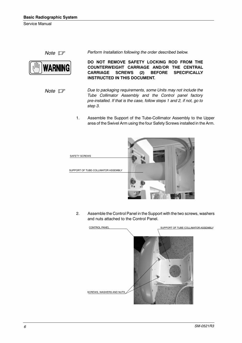
Perform Installation following the order described below.
DO NOT REMOVE SAFETY LOCKING ROD FROM THECOUNTERWEIGHT CARRIAGE AND/OR THE CENTRALCARRIAGE SCREWS (2) BEFORE SPECIFICALLYINSTRUCTED IN THIS DOCUMENT.
Due to packaging requirements, some Units may not include theTube Collimator Assembly and the Control panel factorypre-installed. If that is the case, follow steps 1 and 2, if not, go tostep 3.
1. Assemble the Support of the Tube-Collimator Assembly to the Upperarea of the Swivel Arm using the four Safety Screws installed in the Arm.
SAFETY SCREWS
SUPPORT OF TUBE-COLLIMATOR ASSEMBLY
2. Assemble theControl Panel in the Support with the two screws, washersand nuts attached to the Control Panel.
SUPPORT OF TUBE-COLLIMATOR ASSEMBLYCONTROL PANEL
SCREWS, WASHERS AND NUTS
Note .
Note .

Basic Radiographic System
Service Manual
SM-0521R3 7
3. Assemble the Upper Wall Support to the Column. Lift the Column asmuch as necessary as to mount the Upper Wall Support in its upperpart.
SAFETY SCREWS
At least two people are required to perform the next operation.
4. Position the column against the wall on its final site in the room. Whileone person is holding up the Column, the other one should level itvertically on both lateral sides and on the front. Also use the levelingscrews at the base of the column.
5. Mark its anchoring positions on the wall (not to the floor yet).
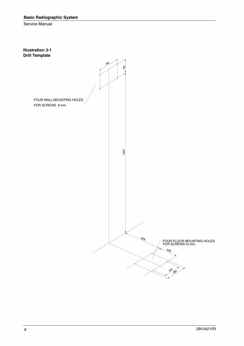
Distances shown on Illustration 3-1 may also be taken asreference to mark the anchoring holes position.
Note .
Note .
Basic Radiographic System
Service Manual
SM-0521R38
Illustration 3-1Drill Template
1839
160
FOUR FLOOR MOUNTING HOLESFOR SCREWS10 mm.
FOUR WALL MOUNTING HOLES
FOR SCREWS 8 mm.
Basic Radiographic System
Service Manual
SM-0521R3 9
6. Move the Column and prepare the anchorages.
BEFORE ANCHORING THE UNIT, CHECK THAT THE WALLAND THE ANCHORING SYSTEM ARE STRONG ENOUGH(2000 NEWTON TRACTION FORCE) TO ENSURE A SAFEINSTALLATION. SOME NON BRICK WALLS MAY REQUIREADDITIONAL ANCHORAGE INSTALLATION.
7. Drill holes and anchor the Wall Support. Make sure the Column is firmlyanchored and leveled at front, sides and base.
8. Install the X-ray Tube in the Upper Support of the Column using theCollimator Adaptation Ring and its four Safety Screws (Allen).
9. Before installing the Collimator, unscrew the same number of turns thefour Centering Adjustment and Safety Screws (Allen) to allow theCollimator installation in the Collimator Adaptation Ring. Adjust theCollimator Blades to their widest setting and carefully install theCollimator centering it with the X-ray Tube window.
Tighten carefully the four Centering Adjustment and Safety Screws(Allen) equally (same number of turns) until Collimator is centered andheld firmly on the Coupling Ring (support). (Also, refer to CollimatorManual).
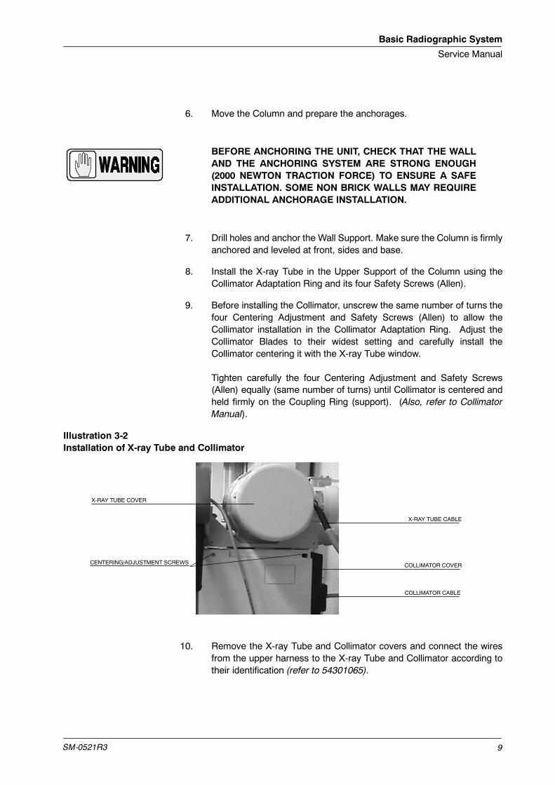
Illustration 3-2Installation of X-ray Tube and Collimator
X-RAY TUBE CABLE
X-RAY TUBE COVER
COLLIMATOR COVER
COLLIMATOR CABLE
CENTERING/ADJUSTMENT SCREWS
10. Remove the X-ray Tube and Collimator covers and connect the wiresfrom the upper harness to the X-ray Tube and Collimator according totheir identification (refer to 54301065).

Basic Radiographic System
Service Manual
SM-0521R310
11. Remove now the Safety Locking Rod from the Counterweight Carriageand the Central Carriage Screws (2). The carriage may go down.
Safety locking Rod
Central Carriage Screw
12. Add all the counterweigh pieces to both entrances at the back side of theColumn and secure them with the provided nuts. The unit is factorycounterweighted, so the counterweights provided are to be installed.
Counterweight entrancesat Column Back
13. Add all the counterweigh pieces to both entrances at the back side of theArm and secure them with the provided nuts. The unit is factorycounterweighted, so all the counterweights provided are to be installed.
Counterweight entrancesat Arm Back
14. Now install the Oscillating Grid Assembly or the Fixed GridAssembly. Follow steps 14 to 17 for Oscillating Grid Assembly or steps18 to 21 for Fixed Grid Assembly.
Basic Radiographic System
Service Manual
SM-0521R3 11
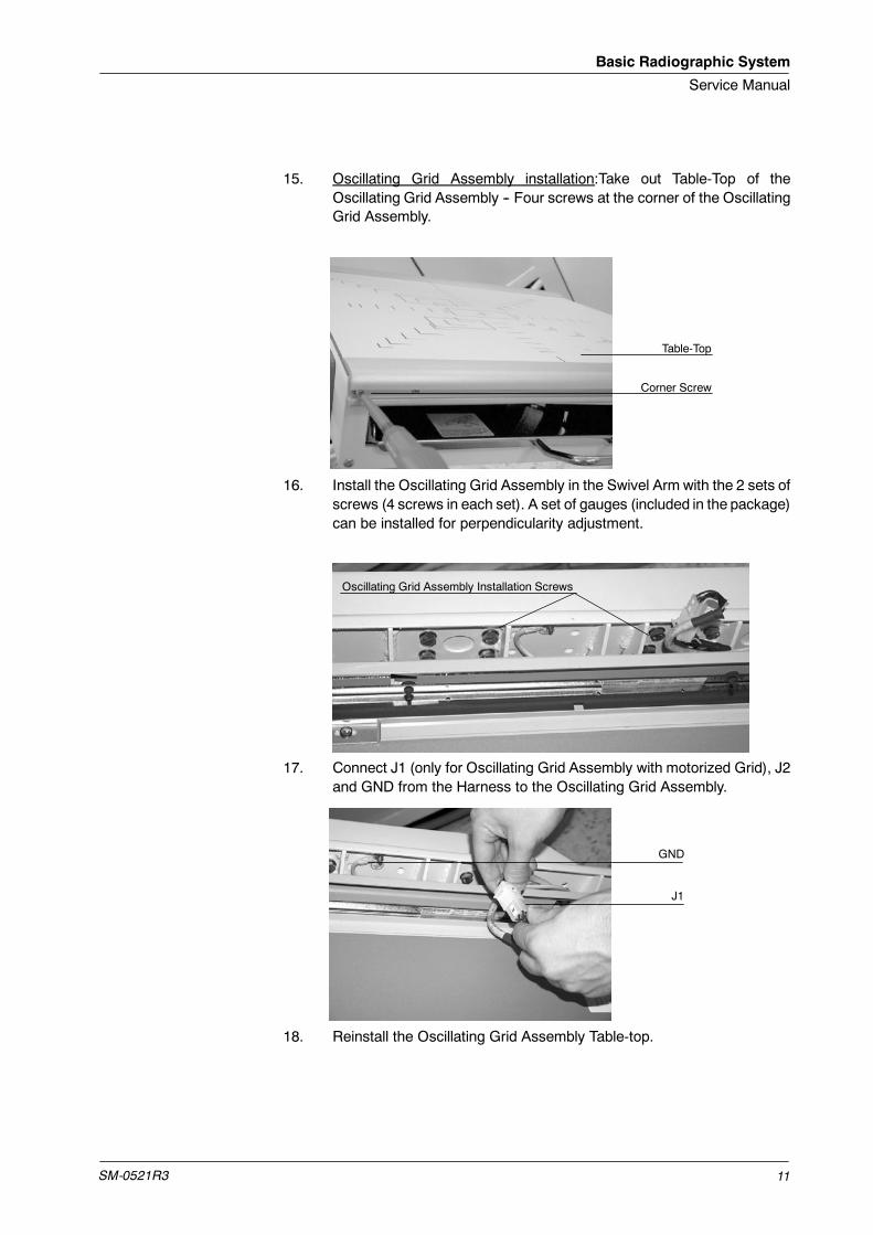
15. Oscillating Grid Assembly installation:Take out Table-Top of theOscillating Grid Assembly -- Four screws at the corner of the OscillatingGrid Assembly.
Table-Top
Corner Screw
16. Install the Oscillating Grid Assembly in the Swivel Arm with the 2 sets ofscrews (4 screws in each set). A set of gauges (included in the package)can be installed for perpendicularity adjustment.
Oscillating Grid Assembly Installation Screws
17. Connect J1 (only for Oscillating Grid Assembly with motorized Grid), J2and GND from the Harness to the Oscillating Grid Assembly.
J1
GND
18. Reinstall the Oscillating Grid Assembly Table-top.
Basic Radiographic System
Service Manual
SM-0521R312
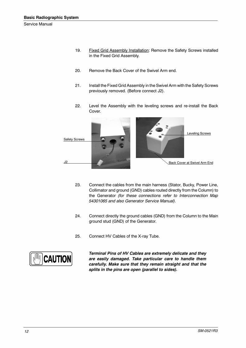
19. Fixed Grid Assembly Installation: Remove the Safety Screws installedin the Fixed Grid Assembly.
20. Remove the Back Cover of the Swivel Arm end.
21. Install the FixedGrid Assembly in the Swivel Armwith the Safety Screwspreviously removed. (Before connect J2).
22. Level the Assembly with the leveling screws and re-install the BackCover.
Safety Screws
Back Cover at Swivel Arm End
Leveling Screws
J2
23. Connect the cables from the main harness (Stator, Bucky, Power Line,Collimator and ground (GND) cables routed directly from the Column) tothe Generator (for these connections refer to Interconnection Map54301065 and also Generator Service Manual).
24. Connect directly the ground cables (GND) from the Column to the Mainground stud (GND) of the Generator.
25. Connect HV Cables of the X-ray Tube.
Terminal Pins of HV Cables are extremely delicate and theyare easily damaged. Take particular care to handle themcarefully. Make sure that they remain straight and that thesplits in the pins are open (parallel to sides).

Basic Radiographic System
Service Manual
SM-0521R3 13
Prepare theHigh Voltage terminals that will be installed in the X-ray Tubereceptacles. Apply Silicone Paste over the entire surface of the Plugincluding the Pins.
Carefully connect cables to their related receptors of the Tube and fixtheir nuts tightly.
26. Fasten HV cables to lateral side of Pivoting Arm with the clamp on thecarriage of the Tube Collimator Assembly. Give the cable length enoughto enable movements of the of Pivoting Arm.
H V Cables
Fasteners
Tube HV Cables may also be tied up to a ceiling pole to avoidcollisions and to easy movements of the system.
27. Mark and drill the anchoring positions on the floor. Check leveling againin different sides of the unit and correct if necessary before fixing the unitdefinitely.
28. Anchor the Column to the floor.
Distances shown on Illustration 3-1 may also be taken asreference to mark the anchoring holes position.
29. Snap in the decorative base of the Columm (pressing it).
30. Turn the system on and check that all controls and movements operatecorrectly.
Note .
Note .

Basic Radiographic System
Service Manual
SM-0521R314
This page intentionally left blank.
Basic Radiographic System
Service Manual
SM-0521R3 15
SECTION 4 ADJUSTMENTS
4.1 ADJUSTMENT TOOLS
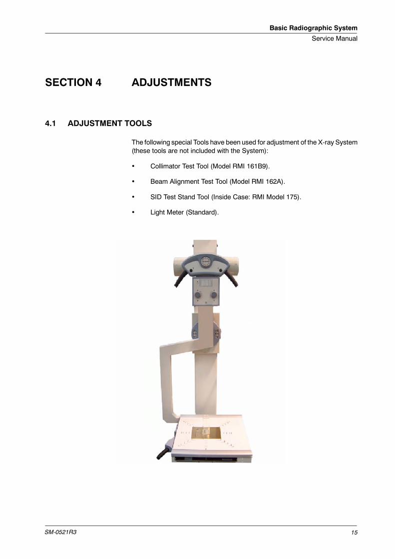
The following special Tools have been used for adjustment of the X-ray System(these tools are not included with the System):
• Collimator Test Tool (Model RMI 161B9).
• Beam Alignment Test Tool (Model RMI 162A).
• SID Test Stand Tool (Inside Case: RMI Model 175).
• Light Meter (Standard).
Basic Radiographic System
Service Manual
SM-0521R316
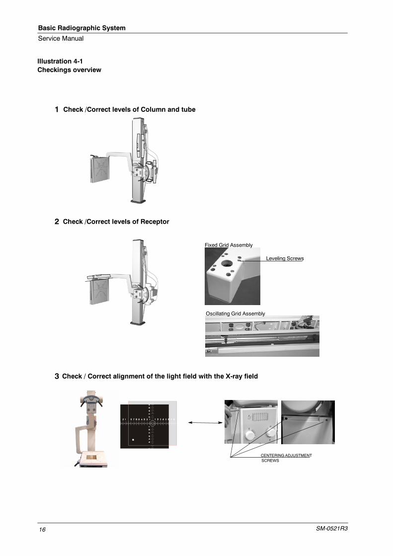
Illustration 4-1Checkings overview
1
2
3
CENTERING ADJUSTMENTSCREWS
Check /Correct levels of Column and tube
Check /Correct levels of Receptor
Check / Correct alignment of the light field with the X-ray field
Leveling Screws
Fixed Grid Assembly
Oscillating Grid Assembly
Basic Radiographic System
Service Manual
SM-0521R3 17
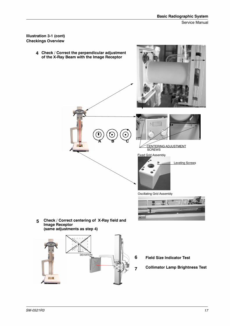
Illustration 3-1 (cont)Checkings Overview
CENTERING ADJUSTMENTSCREWS
5
Check / Correct the perpendicular adjustmentof the X-Ray Beam with the Image Receptor
Check / Correct centering of X-Ray field andImage Receptor(same adjustments as step 4)
4
7
6 Field Size Indicator Test
Collimator Lamp Brightness Test
A B C
DEVIATION
Leveling Screws
Fixed Grid Assembly
Oscillating Grid Assembly
Basic Radiographic System
Service Manual
SM-0521R318
4.2 ALIGNMENT OF X-RAY BEAM
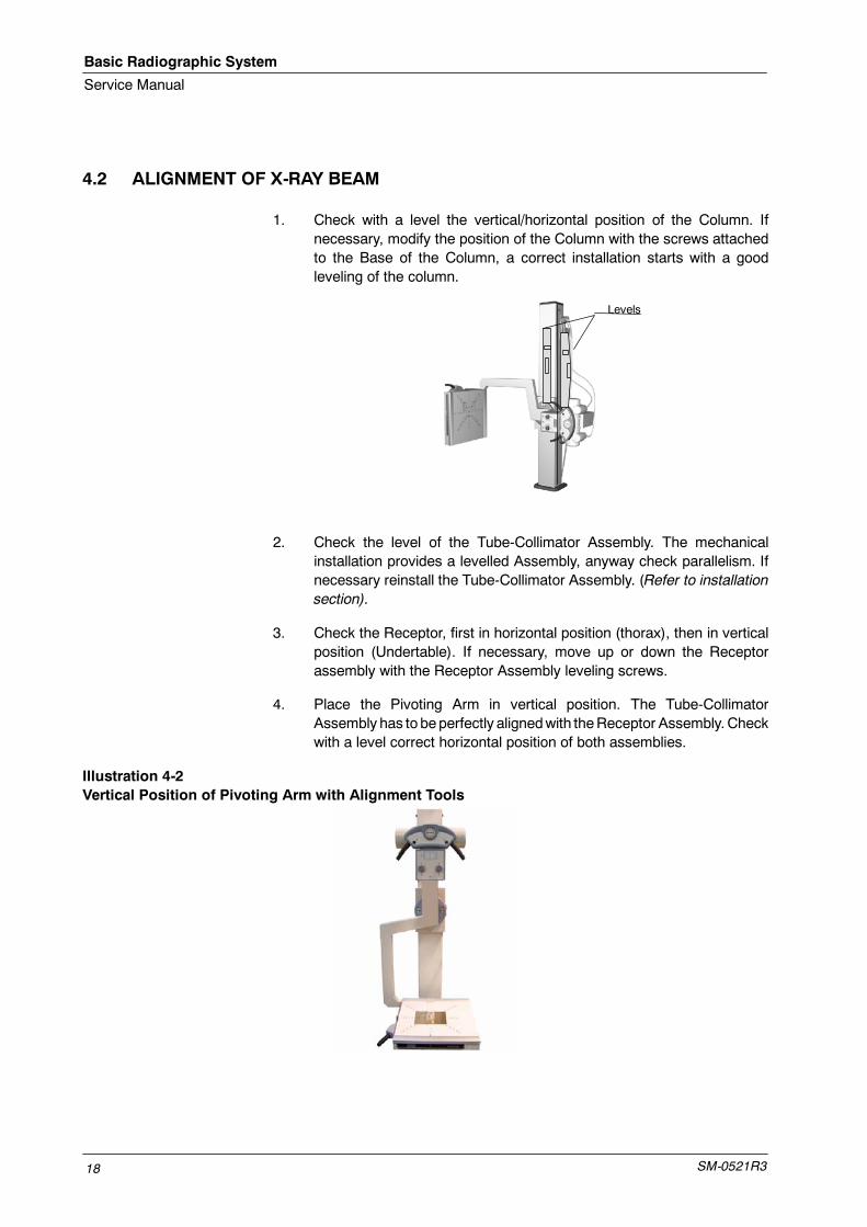
1. Check with a level the vertical/horizontal position of the Column. Ifnecessary, modify the position of the Column with the screws attachedto the Base of the Column, a correct installation starts with a goodleveling of the column.
Levels
2. Check the level of the Tube-Collimator Assembly. The mechanicalinstallation provides a levelled Assembly, anyway check parallelism. Ifnecessary reinstall the Tube-Collimator Assembly. (Refer to installationsection).
3. Check the Receptor, first in horizontal position (thorax), then in verticalposition (Undertable). If necessary, move up or down the Receptorassembly with the Receptor Assembly leveling screws.
4. Place the Pivoting Arm in vertical position. The Tube-CollimatorAssembly has to beperfectly alignedwith theReceptor Assembly. Checkwith a level correct horizontal position of both assemblies.
Illustration 4-2Vertical Position of Pivoting Arm with Alignment Tools
Basic Radiographic System
Service Manual
SM-0521R3 19
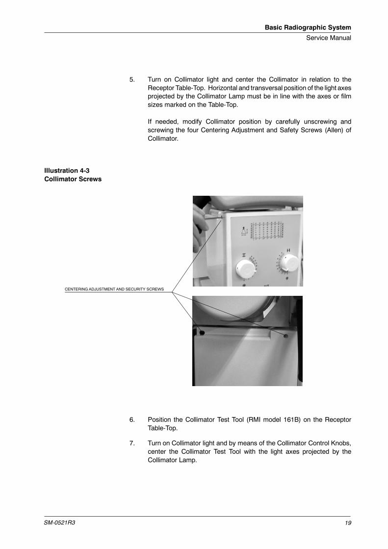
5. Turn on Collimator light and center the Collimator in relation to theReceptor Table-Top. Horizontal and transversal position of the light axesprojected by the Collimator Lamp must be in line with the axes or filmsizes marked on the Table-Top.
If needed, modify Collimator position by carefully unscrewing andscrewing the four Centering Adjustment and Safety Screws (Allen) ofCollimator.
Illustration 4-3Collimator Screws
CENTERING ADJUSTMENT AND SECURITY SCREWS
6. Position the Collimator Test Tool (RMI model 161B) on the ReceptorTable-Top.
7. Turn on Collimator light and by means of the Collimator Control Knobs,center the Collimator Test Tool with the light axes projected by theCollimator Lamp.

Basic Radiographic System
Service Manual
SM-0521R320
8. Adjust the Light Field of the Collimator Lamp to the rectangle drawninside the Collimator Test Tool.
9. Place centered the Beam Alignment Test Tool (RMI model 162A) on theCollimator Test Tool.
Illustration 4-4Alignment Test Tools
BEAM ALIGNMENT TEST TOOL -- RMA MODEL 162A
COLLIMATOR TEST TOOL -- RMA MODEL 161B
10. Load Cassette film Tray with cassette film 24x30 and insert it.
11. Make an exposure at 60 kVp / 5 mAs.
12. Process film and:
a. Check that the X-ray Field falls just within the image of the innerrectangle of the Collimator Test Tool.
If an edge of the X-ray Field falls out of the inner rectangle meansa misalignment of the Light Field respect to the X-ray Field. Themaximummisalignment allowed is 2% of SID (for SID 1.4m = 2.8cm tolerance).
Refer to Section 4.2.1 for alignment of Light Field with X-ray Field.
Basic Radiographic System
Service Manual
SM-0521R3 21
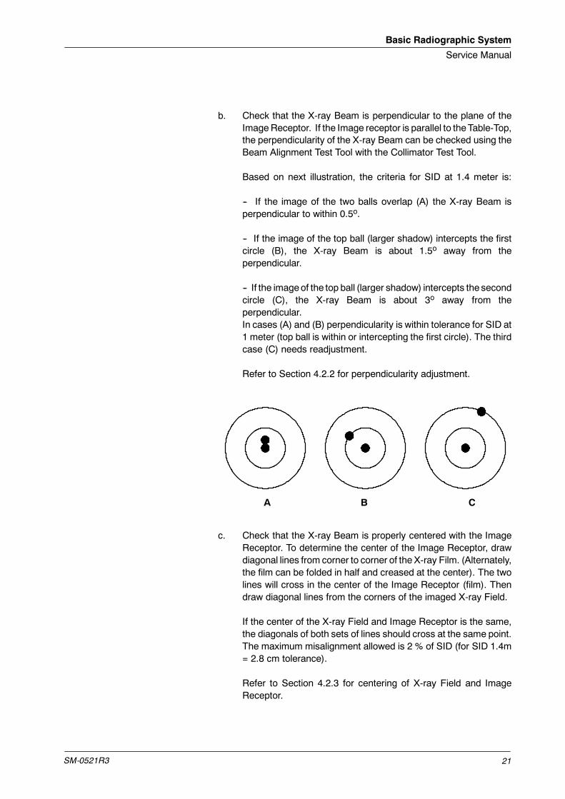
b. Check that the X-ray Beam is perpendicular to the plane of theImageReceptor. If the Image receptor is parallel to theTable-Top,the perpendicularity of the X-ray Beam can be checked using theBeam Alignment Test Tool with the Collimator Test Tool.
Based on next illustration, the criteria for SID at 1.4 meter is:
-- If the image of the two balls overlap (A) the X-ray Beam isperpendicular to within 0.5o.
-- If the image of the top ball (larger shadow) intercepts the firstcircle (B), the X-ray Beam is about 1.5o away from theperpendicular.
-- If the imageof the top ball (larger shadow) intercepts the secondcircle (C), the X-ray Beam is about 3o away from theperpendicular.In cases (A) and (B) perpendicularity is within tolerance for SID at1 meter (top ball is within or intercepting the first circle). The thirdcase (C) needs readjustment.
Refer to Section 4.2.2 for perpendicularity adjustment.
A B C
c. Check that the X-ray Beam is properly centered with the ImageReceptor. To determine the center of the Image Receptor, drawdiagonal lines from corner to corner of the X-ray Film. (Alternately,the film can be folded in half and creased at the center). The twolines will cross in the center of the Image Receptor (film). Thendraw diagonal lines from the corners of the imaged X-ray Field.
If the center of the X-ray Field and Image Receptor is the same,the diagonals of both sets of lines should cross at the same point.The maximum misalignment allowed is 2 % of SID (for SID 1.4m= 2.8 cm tolerance).
Refer to Section 4.2.3 for centering of X-ray Field and ImageReceptor.
Basic Radiographic System
Service Manual
SM-0521R322
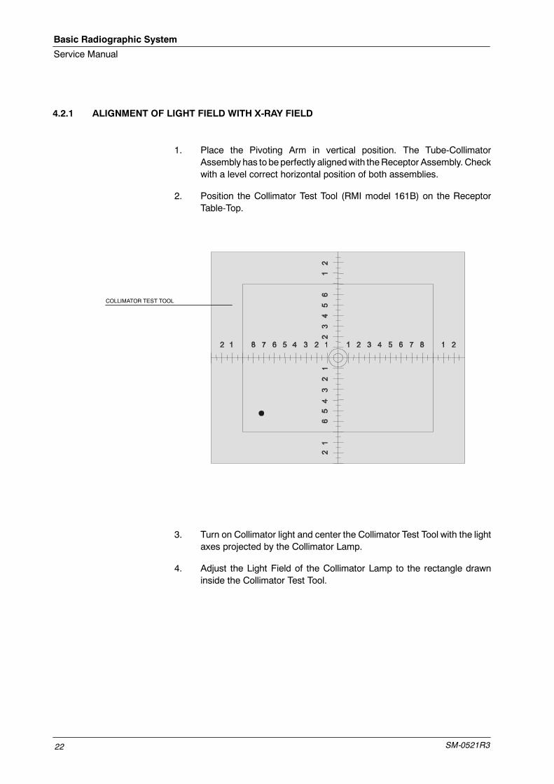
4.2.1 ALIGNMENT OF LIGHT FIELD WITH X-RAY FIELD
1. Place the Pivoting Arm in vertical position. The Tube-CollimatorAssembly has to beperfectly alignedwith theReceptor Assembly. Checkwith a level correct horizontal position of both assemblies.
2. Position the Collimator Test Tool (RMI model 161B) on the ReceptorTable-Top.
COLLIMATOR TEST TOOL
3. Turn on Collimator light and center the Collimator Test Tool with the lightaxes projected by the Collimator Lamp.
4. Adjust the Light Field of the Collimator Lamp to the rectangle drawninside the Collimator Test Tool.
Basic Radiographic System
Service Manual
SM-0521R3 23
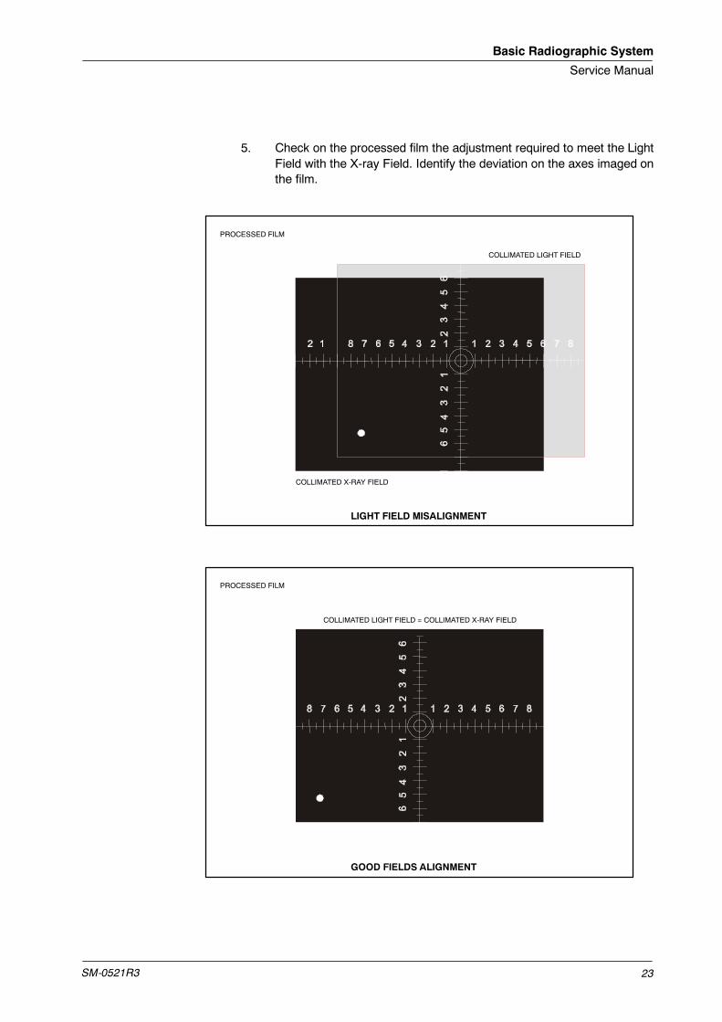
5. Check on the processed film the adjustment required to meet the LightField with the X-ray Field. Identify the deviation on the axes imaged onthe film.
PROCESSED FILM
PROCESSED FILM
COLLIMATED LIGHT FIELD
COLLIMATED X-RAY FIELD
LIGHT FIELD MISALIGNMENT
GOOD FIELDS ALIGNMENT
COLLIMATED LIGHT FIELD = COLLIMATED X-RAY FIELD
Basic Radiographic System
Service Manual
SM-0521R324
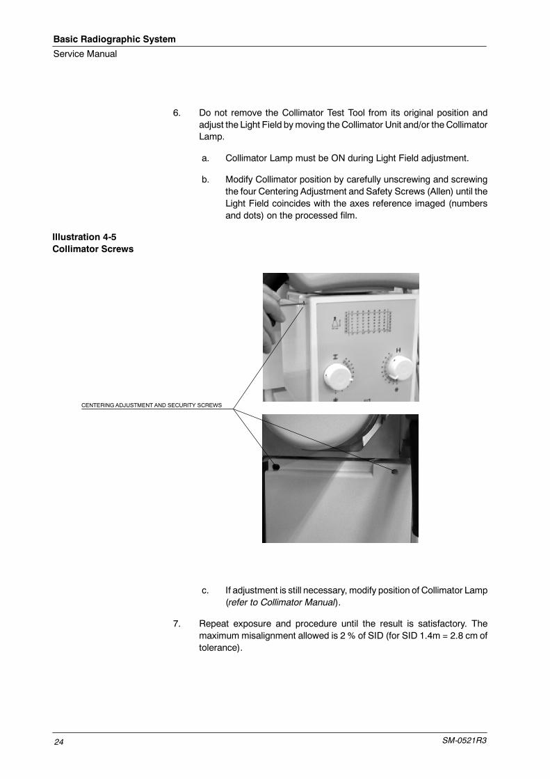
6. Do not remove the Collimator Test Tool from its original position andadjust the Light Field bymoving theCollimator Unit and/or theCollimatorLamp.
a. Collimator Lamp must be ON during Light Field adjustment.
b. Modify Collimator position by carefully unscrewing and screwingthe four Centering Adjustment and Safety Screws (Allen) until theLight Field coincides with the axes reference imaged (numbersand dots) on the processed film.
Illustration 4-5Collimator Screws
CENTERING ADJUSTMENT AND SECURITY SCREWS
c. If adjustment is still necessary, modify position of Collimator Lamp(refer to Collimator Manual).
7. Repeat exposure and procedure until the result is satisfactory. Themaximum misalignment allowed is 2 % of SID (for SID 1.4m = 2.8 cm oftolerance).

Basic Radiographic System
Service Manual
SM-0521R3 25
4.2.2 PERPENDICULARITY ADJUSTMENT OF X-RAY BEAM WITH IMAGE RECEPTOR
In case that perpendicularity is out of tolerance (top ball is out of first circle),adjust perpendicularity as follows:
1. Place the Pivoting Arm in vertical position. The Tube-CollimatorAssembly has to beperfectly alignedwith theReceptor Assembly. Checkwith a level correct horizontal position of both assemblies.
The Receptor Assembly is factory adjusted (slightly up) and it isrecommended do not perform any additional correction. Duringprocedure, it must behorizontally placedat 0o (check positionwith a leveland with its indicator plate).
2. Position the Collimator Test Tool (RMI model 161B) on the ReceptorTable-Top.
3. Turn on Collimator light and center the Collimator Test Tool with the lightaxes projected by the Collimator Lamp.
4. Place centered the Beam Alignment Test Tool (RMI model 162A) on theCollimator Test Tool and observe if shadow of the Beam Alignment TestTool is projected in equal proportion around it.
5. Check on the processed film the adjustment required to center the topball mark. Shadow around the Beam Alignment Test Tool can also helpto make a first correction.
6. Loosen slightly the four Safety Screws (Allen M8) of the Tube-CollimatorAssembly. If required, perform the following adjustments:
G For horizontal correction move horizontally the Tube-CollimatorAssembly before tightening the four Safety Screws.
G For vertical correction loosen or tighten carefully the four LevelingScrews (Allen M6) of the Tube-Collimator Assembly beforetightening the four Safety Screws.
7. Repeat exposure and procedure until the result is satisfactory (top ballmust be inside of the first circle).
Basic Radiographic System
Service Manual
SM-0521R326
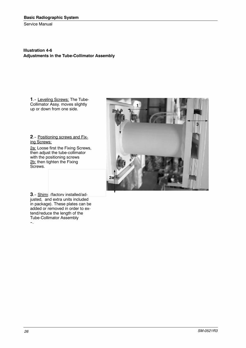
Illustration 4-6Adjustments in the Tube-Collimator Assembly
1.-- Leveling Screws: The Tube-Collimator Assy. moves slightlyup or down from one side.
2.-- Positioning screws and Fix-ing Screws:
2a: Loose first the Fixing Screws,then adjust the tube-collimatorwith the positioning screws2b: then tighten the FixingScrews.
3.-- Shims (factory installed/ad-justed, and extra units includedin package). These plates can beadded or removed in order to ex-tend/reduce the length of theTube-Collimator Assembly--.
12b
3
2a
Basic Radiographic System
Service Manual
SM-0521R3 27
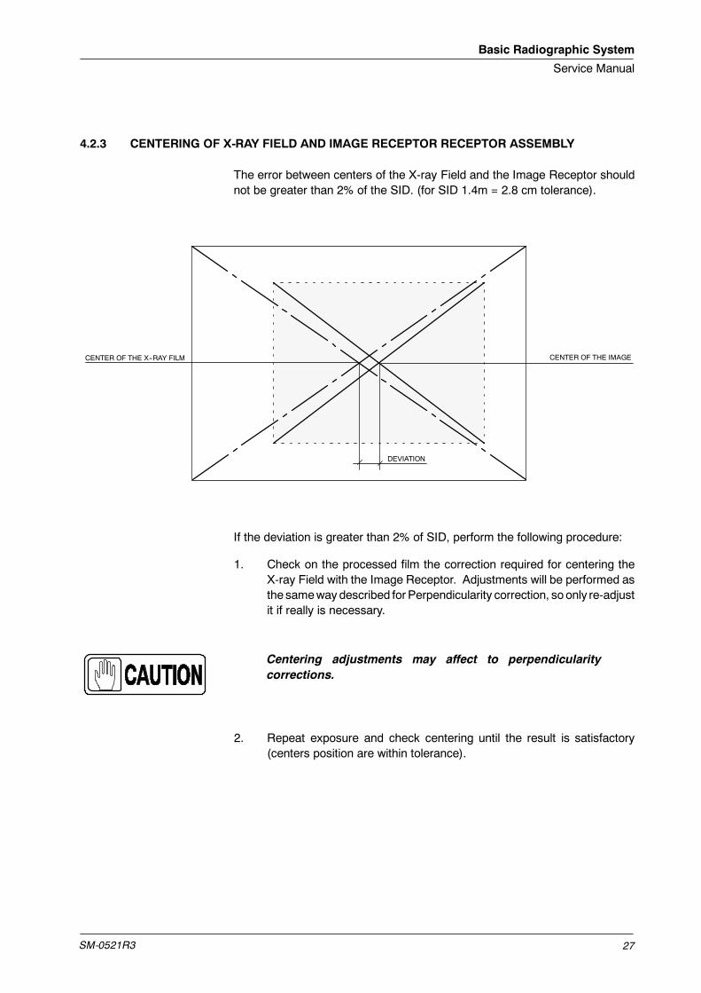
4.2.3 CENTERING OF X-RAY FIELD AND IMAGE RECEPTOR RECEPTOR ASSEMBLY
The error between centers of the X-ray Field and the Image Receptor shouldnot be greater than 2% of the SID. (for SID 1.4m = 2.8 cm tolerance).
CENTER OF THE X--RAY FILM CENTER OF THE IMAGE
DEVIATION
If the deviation is greater than 2% of SID, perform the following procedure:
1. Check on the processed film the correction required for centering theX-ray Field with the Image Receptor. Adjustments will be performed asthe samewaydescribed for Perpendicularity correction, soonly re-adjustit if really is necessary.
Centering adjustments may affect to perpendicularitycorrections.
2. Repeat exposure and check centering until the result is satisfactory(centers position are within tolerance).

Basic Radiographic System
Service Manual
SM-0521R328
4.3 FIELD SIZE INDICATOR TEST
Before starting with the Field Size Indicator Test, the Alignment ofX-Ray Beam Test, the Alignment of Light Field with X-Ray FieldTest and the SID Indicator Test should be performed.
1. Place the Pivoting Arm in vertical position. The Tube-CollimatorAssembly has to beperfectly alignedwith theReceptor Assembly. Checkwith a level correct horizontal position of both assemblies.
2. Open the Collimator blades to set a Field Size of 24 x 30 cm for SID1,4 m.
3. Turn on the Collimator Light and center the Collimator in relation to theReceptor Table-Top. Horizontal and transversal position of the light axesprojected by the Collimator Lamp must be in line with the axes or FilmSize marked on the Table-Top.
Note .
Basic Radiographic System
Service Manual
SM-0521R3 29
4. Load on the Cassette Film Tray with a Cassette Film of 35 x 43 cmcentered and insert it.
5. Make an exposure at 60kVp, 1mAs.
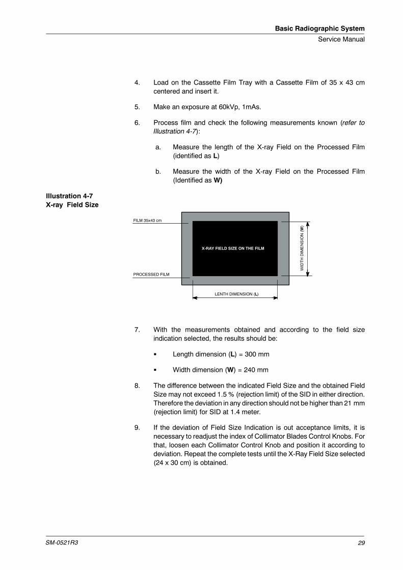
6. Process film and check the following measurements known (refer toIllustration 4-7):
a. Measure the length of the X-ray Field on the Processed Film(identified as L)
b. Measure the width of the X-ray Field on the Processed Film(Identified as W)
Illustration 4-7X-ray Field Size
X-RAY FIELD SIZE ON THE FILM
FILM 35x43 cm
PROCESSED FILM
LENTH DIMENSION (L)
WIDTHDIMENSION(W
)
7. With the measurements obtained and according to the field sizeindication selected, the results should be:
G Length dimension (L) = 300 mm
G Width dimension (W) = 240 mm
8. The difference between the indicated Field Size and the obtained FieldSize may not exceed 1.5 % (rejection limit) of the SID in either direction.Therefore the deviation in any direction should not be higher than 21 mm(rejection limit) for SID at 1.4 meter.
9. If the deviation of Field Size Indication is out acceptance limits, it isnecessary to readjust the index of Collimator Blades Control Knobs. Forthat, loosen each Collimator Control Knob and position it according todeviation. Repeat the complete tests until the X-Ray Field Size selected(24 x 30 cm) is obtained.
Basic Radiographic System
Service Manual
SM-0521R330
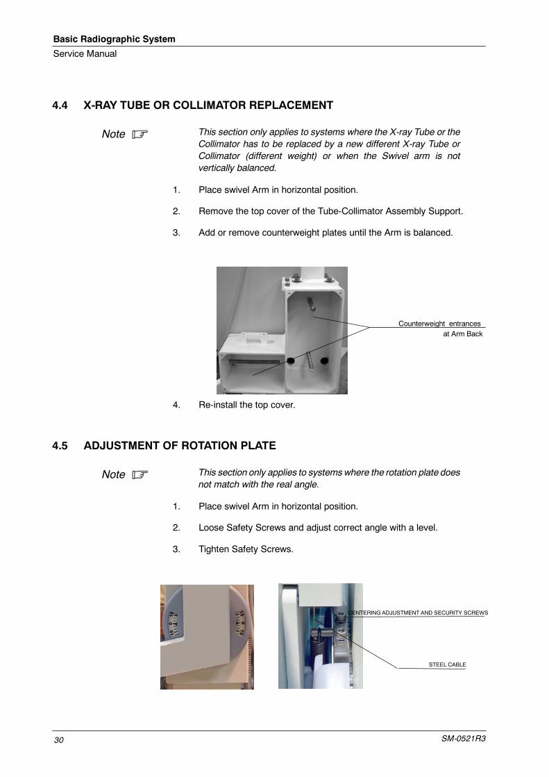
4.4 X-RAY TUBE OR COLLIMATOR REPLACEMENT
This section only applies to systems where the X-ray Tube or theCollimator has to be replaced by a new different X-ray Tube orCollimator (different weight) or when the Swivel arm is notvertically balanced.
1. Place swivel Arm in horizontal position.
2. Remove the top cover of the Tube-Collimator Assembly Support.
3. Add or remove counterweight plates until the Arm is balanced.
Counterweight entrancesat Arm Back
4. Re-install the top cover.
4.5 ADJUSTMENT OF ROTATION PLATE
This section only applies to systemswhere the rotation plate doesnot match with the real angle.
1. Place swivel Arm in horizontal position.
2. Loose Safety Screws and adjust correct angle with a level.
3. Tighten Safety Screws.
CENTERING ADJUSTMENT AND SECURITY SCREWS
STEEL CABLE
Note .
Note .
Basic Radiographic System
Service Manual
SM-0521R3 31
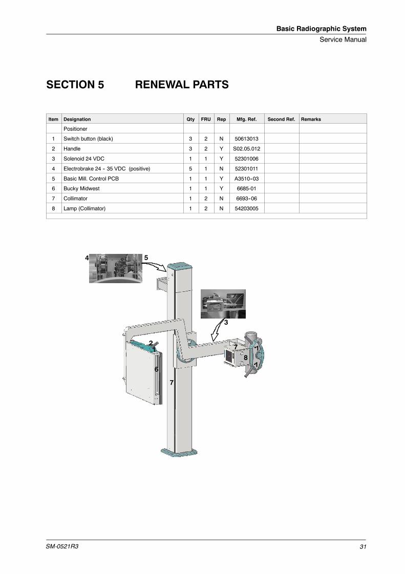
SECTION 5 RENEWAL PARTS
Item Designation Qty FRU Rep Mfg. Ref. Second Ref. Remarks
Positioner
1 Switch button (black) 3 2 N 50613013
2 Handle 3 2 Y S02.05.012
3 Solenoid 24 VDC 1 1 Y 52301006
4 Electrobrake 24 -- 35 VDC (positive) 5 1 N 52301011
5 Basic Mill. Control PCB 1 1 Y A3510--03
6 Bucky Midwest 1 1 Y 6685-01
7 Collimator 1 2 N 6693--06
8 Lamp (Collimator) 1 2 N 54203005
18
7
7
6
5
3
4
21
1

Basic Radiographic System
Service Manual
SM-0521R332
This page intentionally left blank.

Basic Radiographic System
Service Manual
SM-0521R3 33
SECTION 6 MAINTENANCE
The Optima BRS has been designed as a long term X--ray positioner withminimum maintenance.
The mechanical parts of the Optima BRS require a yearly basis servicemaintenance from the installation date in the following way:
Visual Check: Covers, Pushbuttons, Table-top, Receptor Assembly, SteelCables appareance (from the Column Slot side), connectors and electricalcables.
Functional Check: Push-buttons, movements of the carriageand arm, cassettetray, perform an exposure and check correct alignment of film, Collimator andCollimator light (refer to Section 4).
Yearly Functional Check
ITEM ACTION
Push-buttons Visual Check, correct contact and corresponding movement.
Movement of Carriage Check complete travel of carriage, it should be soft and noiseless
Movement of Arm Check complete angle travel of the Arm, it should be soft and noiseless.
Both Steel Cables Move carriage to the lowest position and check appareance of both steel cables from the side slotof the column. Check connection plate and disassembly top cover to check the whole cable travel.They should be in without stranded or broken hairs.
Cassette Tray Check correct positioning inside Receptor assembly, correct clamping of film.
Collimator and Tube Refer to Section 4 in this Manual and Generator maintenance Section.

Basic Radiographic System
Service Manual
SM-0521R334
This page intentionally left blank.
Basic Radiographic System
Service Manual
SM-0521R3 35
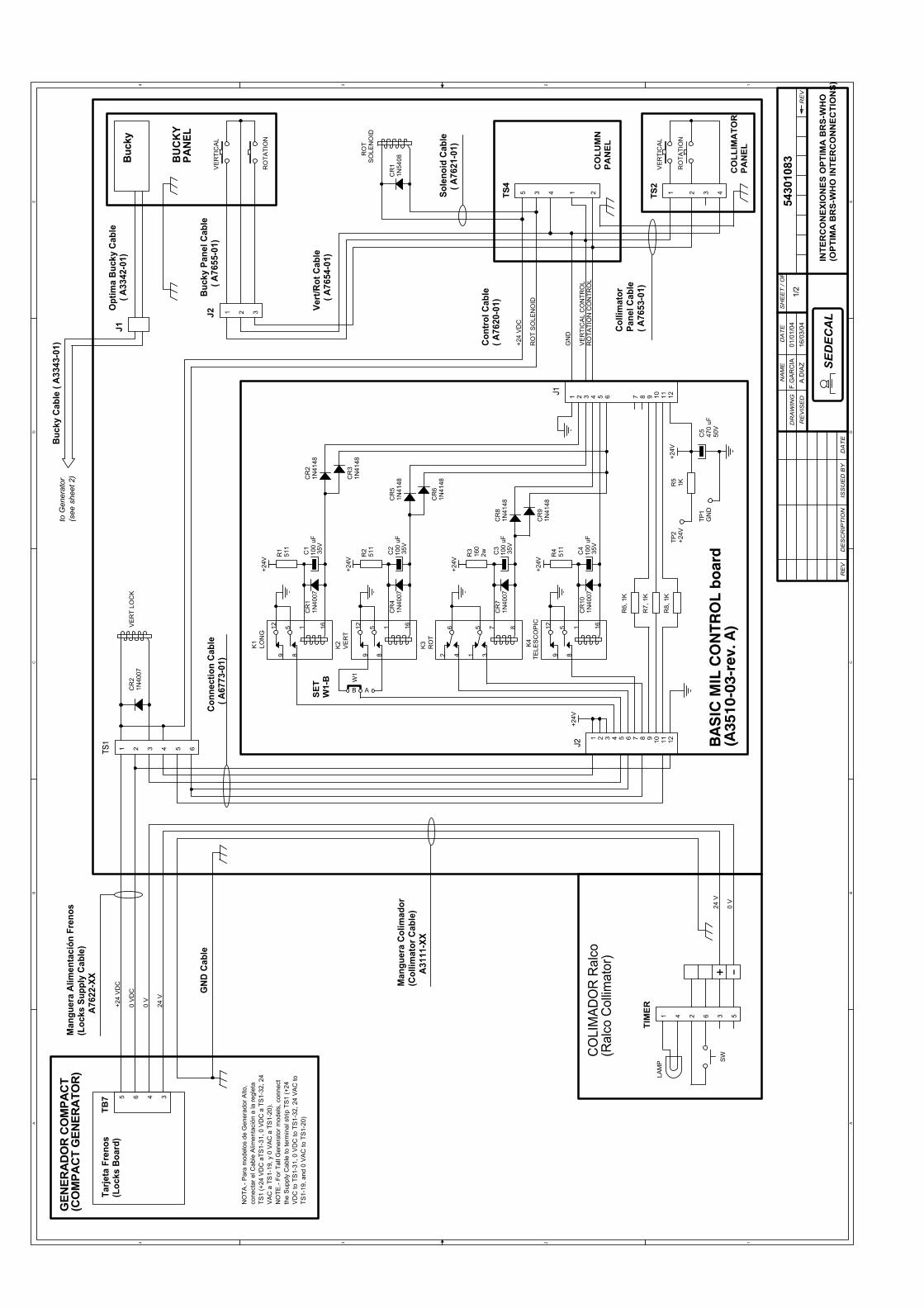
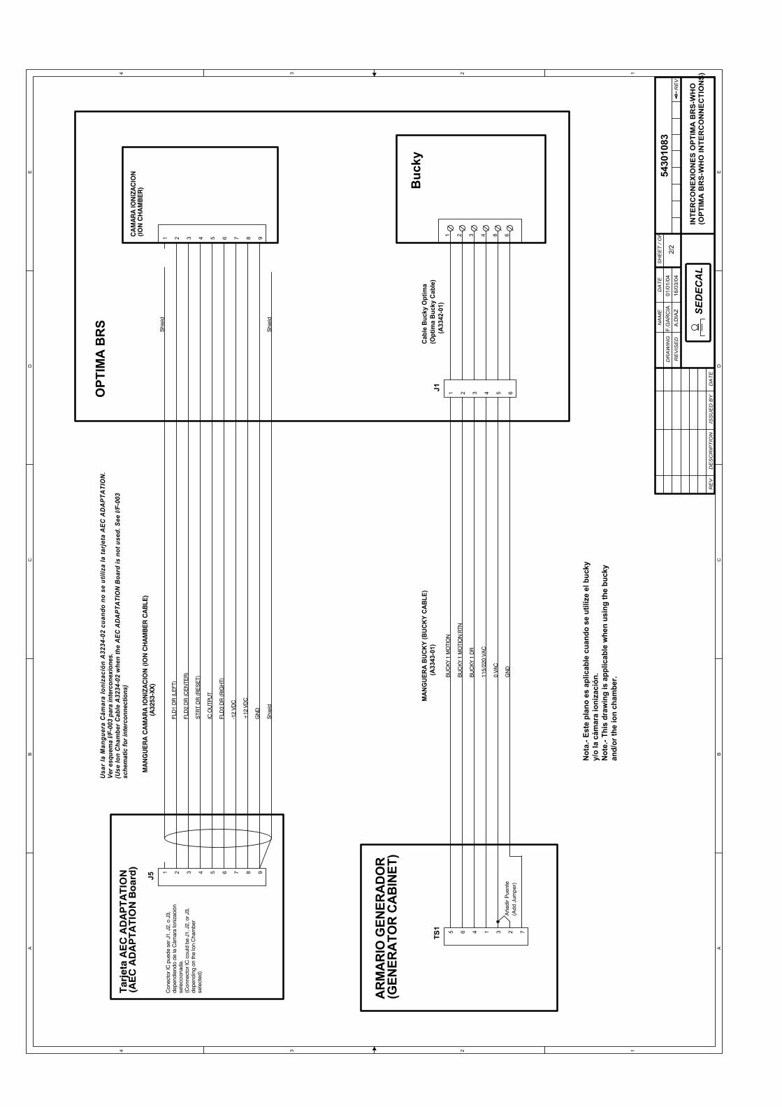
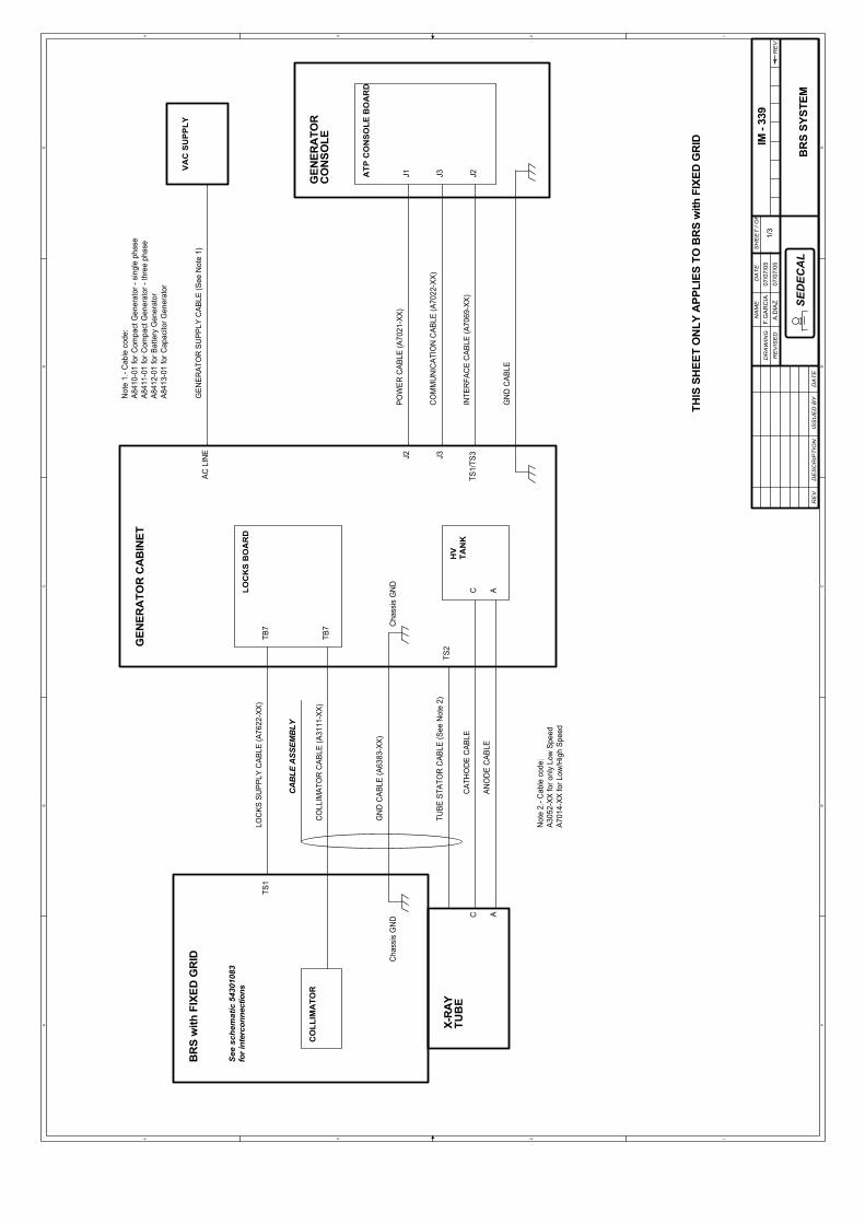
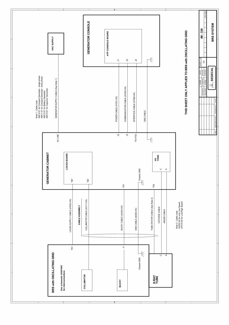
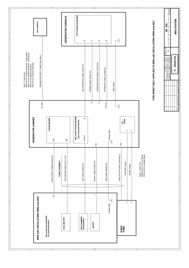
SECTION 7 INTERCONNECTION MAPS
Refer to the following maps for details of the wire connections.
• Optima BRS-Who interconnections 54301083. . . . . . . . . . . .
• BRS System IM-339. . . . . . . . . . . . . . . . . . . . . . . . . . . . . . . .

Basic Radiographic System
Service Manual
SM-0521R336
This page intentionally left blank.
A A
B B
C C
D D
E E
44
33
22
11
INTE
RC
ON
EX
ION
ES
OP
TIM
A B
RS
-WH
O(O
PTI
MA
BR
S-W
HO
INTE
RC
ON
NE
CTI
ON
S)
BA
SIC
MIL
CO
NTR
OL
boar
d(A
3510
-03-
rev.
A)
GN
D C
able
0 V
DC
+24
VD
C
GEN
ERA
DO
R C
OM
PAC
T(C
OM
PAC
T G
ENER
ATO
R)
Tarje
ta F
reno
s(L
ocks
Boa
rd)
NO
TA.-
Par
a m
odel
os d
e G
ener
ador
Alto
,co
nect
ar e
l Cab
le A
limen
taci
ón a
la re
glet
aTS
1 (+
24 V
DC
aTS
1-31
, 0 V
DC
a T
S1-
32, 2
4V
AC
a T
S1-
19, y
0 V
AC
a T
S1-
20).
NO
TE.-
For T
all G
ener
ator
mod
els,
con
nect
the
Sup
ply
Cab
le to
term
inal
stri
p TS
1 (+
24V
DC
to T
S1-
31, 0
VD
C to
TS
1-32
, 24
VA
C to
TS1-
19, a
nd 0
VA
C to
TS
1-20
)
Man
guer
a C
olim
ador
(Col
limat
or C
able
)
A31
11-X
X
CO
LIM
ADO
R R
alco
(Ral
co C
ollim
ator
)
24 V
0 V
Man
guer
a A
limen
taci
ón F
reno
s(L
ocks
Sup
ply
Cab
le)
A
7622
-XX
CO
LUM
NP
AN
EL
VE
RTI
CA
L C
ON
TRO
LR
OTA
TIO
N C
ON
TRO
L
GN
D
24 V
0 V
Opt
ima
Buc
ky C
able
(
A33
42-0
1)
Buc
ky C
able
( A
3343
-01)
to G
ener
ator
(see
she
et 2
)
BU
CK
YPA
NEL
Buc
ky
Buc
ky P
anel
Cab
le
( A
7655
-01)
Vert
/Rot
Cab
le
( A
7654
-01)
CO
LLIM
ATO
RP
AN
EL
Col
limat
orPa
nel C
able
( A76
53-0
1)
Con
trol
Cab
le( A
7620
-01)
J1
Con
nect
ion
Cab
le
( A67
73-0
1)
Sole
noid
Cab
le
( A76
21-0
1)
+ -
+24
VD
C
RO
T S
OLE
NO
ID
SE
TW
1-B
5430
1083
1/2
01/0
1/04
F.G
AR
CIA
16/0
3/04
A.D
IAZ
RE
VD
ES
CR
IPT
ION
ISS
UE
D B
YD
AT
E
DR
AW
ING
RE
VIS
ED
NA
ME
DA
TE
SH
EE
T /
OF
RE
V
SE
DE
CA
L
+24V
+24V
+24V
+24V
+24V
+24V
CR
71N
4007
CR
81N
4148
C2
100
uF35
V
C1
100
uF35
V
CR
31N
4148
CR
51N
4148
RO
TATI
ON
CR
21N
4007
CR
11N
5408
CR
61N
4148
J2 1 2 3
CR
91N
4148
C3
100
uF35
V
J1 1 2 3 4 5 6 7 8 9 10 11 12
J2
1 2 3 4 5 6 7 8 9 10 11 12
R6,
1K
R7,
1K
R8,
1K
K3
RO
T
51
873
642
TB7 5 6 4 3
CR
11N
4007
SO
LEN
OID
RO
T
CR
41N
4007
CR
21N
4148
K1
LON
G
59 8
1 1612
K2
VE
RT
59 8
1 1612
RO
TATI
ON
VE
RTI
CA
L
K4
TELE
SC
OP
IC 59 8
1 1612
TS2
1 2 3 4
R2
511
TS1
1 2 3 4 5 6
C5
470
uF50
V
TS4
1 23 45
LAM
P
TIM
ER
1 2 34 56
AB
W1
CR
101N
4007
R3
160
2w
SW
R4
511
VE
RT
LOC
K
R1
511
R5
1K+2
4VTP
2
GN
DTP
1
C4
100
uF35
V
VE
RTI
CA
L

A A
B B
C C
D D
E E
44
33
22
11
Aña
dir P
uent
e(A
dd J
umpe
r)
AR
MA
RIO
GEN
ERA
DO
R(G
ENER
ATO
R C
AB
INET
)
MAN
GUE
RA B
UCKY
(BUC
KY C
ABLE
)
(A33
43-0
1)
BU
CKY
1 M
OTI
ON
BU
CKY
1 M
OTI
ON
RTN
BU
CKY
1 D
R
115/
220
VAC
0 VA
C
INTE
RC
ON
EX
ION
ES
OP
TIM
A B
RS
-WH
O(O
PTI
MA
BR
S-W
HO
INTE
RC
ON
NE
CTI
ON
S)
GN
D
Buc
kyCa
ble
Buck
y O
ptim
a(O
ptim
a Bu
cky
Cabl
e)
(A
3342
-01)
OPT
IMA
BR
S
Not
a.- E
ste
plan
o es
apl
icab
le c
uand
o se
util
ize
el b
ucky
y/o
la c
ámar
a io
niza
ción
.N
ote.
- Thi
s dr
awin
g is
app
licab
le w
hen
usin
g th
e bu
cky
and/
or th
e io
n ch
ambe
r.
MA
NG
UER
A C
AM
AR
A IO
NIZ
AC
ION
(IO
N C
HAM
BER
CAB
LE)
(A
3253
-XX)
Shi
eld
IC O
UTP
UT
Con
ecto
r IC
pue
de s
er J
1, J
2, o
J3,
depe
ndie
ndo
de la
Cám
ara
Ioni
zaci
ónse
lecc
iona
da.
(Con
nect
or IC
cou
ld b
e J1
, J2,
or J
3,de
pend
ing
on th
e Io
n C
ham
ber
sele
cted
)
CA
MAR
A IO
NIZ
ACIO
N(IO
N C
HA
MB
ER)
FLD
1 D
R (L
EFT)
FLD
3 D
R (R
IGH
T)
GN
D
FLD
2 D
R (C
ENTE
R)
STR
T D
R (R
ES
ET)
+12
VD
C
Shi
eld
-12
VDC
Tarj
eta
AE
C A
DA
PTA
TIO
N(A
EC
AD
AP
TATI
ON
Boa
rd)
Shi
eld
Usa
r la
Man
guer
a C
ámar
a Io
niza
ción
A32
34-0
2 cu
ando
no
se u
tiliz
a la
tarj
eta
AEC
AD
APT
ATI
ON
.Ve
r esq
uem
a I/F
-003
par
a in
terc
onex
ione
s.(U
se Io
n C
ham
ber C
able
A32
34-0
2 w
hen
the
AEC
AD
APT
ATI
ON
Boa
rd is
not
use
d. S
ee I/
F-00
3sc
hem
atic
for i
nter
conn
ectio
ns)
5430
1083
2/2
01/0
1/04
F.G
AR
CIA
16/0
3/04
A.D
IAZ
RE
VD
ES
CR
IPT
ION
ISS
UE
D B
YD
AT
E
DR
AW
ING
RE
VIS
ED
NA
ME
DA
TE
SH
EE
T /
OF
RE
V
SE
DEC
AL
J1 5 641 32
151 2 6 9873 4 2 3 4 8 6
TS1 5 6 4 1 3 2 7
J5
51 2 6 9873 4

A A
B B
C C
D D
E E
44
33
22
11
BR
S SY
STEM
See
sch
emat
ic 5
4301
083
for i
nter
conn
ectio
ns
BR
S w
ith F
IXED
GR
ID
LOC
KS S
UPP
LY C
ABLE
(A76
22-X
X)TS
1
CO
LLIM
ATO
R C
ABLE
(A31
11-X
X)
GEN
ERA
TOR
CA
BIN
ET
TB7
LOC
KS
BO
AR
D
TB7
CO
LLIM
ATO
R
GEN
ERAT
OR
SU
PPLY
CAB
LE (S
ee N
ote
1)
TUBE
STA
TOR
CAB
LE (S
ee N
ote
2)TS
2X-
RA
YTU
BE
GN
D C
ABLE
(A63
83-X
X)
Cha
ssis
GN
DC
hass
is G
ND
CA
BLE
ASS
EMB
LY
AC L
INE
VA
C S
UP
PLY
Not
e 1.
- Cab
le c
ode:
A841
0-01
for C
ompa
ct G
ener
ator
- si
ngle
pha
seA8
411-
01 fo
r Com
pact
Gen
erat
or -
thre
e ph
ase
A841
2-01
for B
atte
ry G
ener
ator
A841
3-01
for C
apac
itor G
ener
ator
THIS
SH
EET
ON
LY A
PPLI
ES T
O B
RS
with
FIX
ED G
RID
Not
e 2.
- Cab
le c
ode:
A305
2-XX
for o
nly
Low
Spe
edA7
014-
XX fo
r Low
/Hig
h Sp
eed
J1 J3
POW
ER C
ABLE
(A70
21-X
X)
J3
INTE
RFA
CE
CAB
LE (A
7069
-XX)
GEN
ERA
TOR
CO
NSO
LE
ATP
CO
NS
OLE
BO
AR
D
GN
D C
ABLE
TS1/
TS3
CO
MM
UN
ICAT
ION
CAB
LE (A
7022
-XX)
J2
J2
AAN
OD
E C
ABLE
C
HV
TAN
KC
ATH
OD
E C
ABLE
AC
IM -
339
1/3
07/0
7/05
F.G
AR
CIA
07/0
7/05
A.D
IAZ
RE
VD
ES
CR
IPT
ION
ISS
UE
D B
YD
AT
E
DR
AW
ING
RE
VIS
ED
NA
ME
DA
TE
SH
EE
T /
OF
RE
V
SE
DE
CA
L

A A
B B
C C
D D
E E
44
33
22
11
BR
S SY
STEM
J1
GEN
ERA
TOR
CA
BIN
ET
AC L
INE
J2
TS1
BR
S w
ith O
SCIL
LATI
NG
GR
ID
TB7
J3
Cha
ssis
GN
D
X-R
AY
TUB
E
GN
D C
ABLE
(A63
83-X
X)
TS2
J2
CO
LLIM
ATO
R C
ABLE
(A31
11-X
X)
J3
LOC
KS
BO
AR
D
BU
CK
Y
LOC
KS S
UPP
LY C
ABLE
(A76
22-X
X)
J1
TB7
TS1/
TS3
INTE
RFA
CE
CAB
LE (A
7069
-XX)
TS1
BUC
KY C
ABLE
(A33
43-X
X)
GEN
ERA
TOR
CO
NSO
LE
VA
C S
UP
PLY
Cha
ssis
GN
D
POW
ER C
ABLE
(A70
21-X
X)
GN
D C
ABLE
CO
MM
UN
ICAT
ION
CAB
LE (A
7022
-XX)
CO
LLIM
ATO
R
See
sch
emat
ic 5
4301
083
for i
nter
conn
ectio
ns
ATP
CO
NS
OLE
BO
AR
D
CA
BLE
ASS
EMB
LY
Not
e 1.
- Cab
le c
ode:
A841
0-01
for C
ompa
ct G
ener
ator
- si
ngle
pha
seA8
411-
01 fo
r Com
pact
Gen
erat
or -
thre
e ph
ase
A841
2-01
for B
atte
ry G
ener
ator
A841
3-01
for C
apac
itor G
ener
ator
GEN
ERAT
OR
SU
PPLY
CAB
LE (S
ee N
ote
1)
THIS
SH
EET
ON
LY A
PPLI
ES T
O B
RS
with
OSC
ILLA
TIN
G G
RID
Not
e 2.
- Cab
le c
ode:
A305
2-XX
for o
nly
Low
Spe
edA7
014-
XX fo
r Low
/Hig
h Sp
eed
TUBE
STA
TOR
CAB
LE (S
ee N
ote
2)
AAN
OD
E C
ABLE
C
HV
TAN
KC
ATH
OD
E C
ABLE
AC
IM -
339
2/3
07/0
7/05
F.G
AR
CIA
07/0
7/05
A.D
IAZ
RE
VD
ES
CR
IPT
ION
ISS
UE
D B
YD
AT
E
DR
AW
ING
RE
VIS
ED
NA
ME
DA
TE
SH
EE
T /
OF
RE
V
SE
DE
CA
L

A A
B B
C C
D D
E E
44
33
22
11
Cha
ssis
GN
D
BU
CK
Y
CO
LLIM
ATO
RTB
7
LOC
KS
BO
AR
D
AEC
INTE
RFA
CE
CAB
LE (A
3251
-01)
CA
BLE
ASS
EMB
LY
X-R
AY
TUB
E
ATP
CO
NS
OLE
BO
AR
D
GEN
ERA
TOR
CA
BIN
ET
See
sch
emat
ic 5
4301
083
for i
nter
conn
ectio
ns
J1/J
2/J3
GEN
ERA
TOR
CO
NSO
LE
See
sch
emat
ic IM
-010
TB7
Cha
ssis
GN
D
AEC
CAB
LE (A
3253
-XX)
AE
C A
DA
PTA
TIO
N B
OA
RD
TS1
ION
CH
AM
BE
R(P
ream
plifi
er)
TS2
TS1
J3
CO
LLIM
ATO
R C
ABLE
(A31
11-X
X)
BUC
KY C
ABLE
(A33
43-X
X)
J1
GN
D C
ABLE
(A63
83-X
X)
J1
LOC
KS S
UPP
LY C
ABLE
(A76
22-X
X)
J4J5
BR
S w
ith O
SCIL
LATI
NG
GR
ID a
nd A
EC
BR
S SY
STEM
J2 J3
POW
ER C
ABLE
(A70
21-X
X)
CO
MM
UN
ICAT
ION
CAB
LE (A
7022
-XX)
J2IN
TER
FAC
E C
ABLE
(A70
69-X
X)TS
1/TS
3
GN
D C
ABLE
VA
C S
UP
PLY
AC L
INE
THIS
SH
EET
ON
LY A
PPLI
ES T
O B
RS
with
OSC
ILLA
TIN
G G
RID
and
AEC
GEN
ERAT
OR
SU
PPLY
CAB
LE (S
ee N
ote
1)
Not
e 1.
- Cab
le c
ode:
A841
0-01
for C
ompa
ct G
ener
ator
- si
ngle
pha
seA8
411-
01 fo
r Com
pact
Gen
erat
or -
thre
e ph
ase
A841
2-01
for B
atte
ry G
ener
ator
A841
3-01
for C
apac
itor G
ener
ator
TUBE
STA
TOR
CAB
LE (S
ee N
ote
2)
Not
e 2.
- Cab
le c
ode:
A305
2-XX
for o
nly
Low
Spe
edA7
014-
XX fo
r Low
/Hig
h Sp
eed
AAN
OD
E C
ABLE
C
HV
TAN
KC
ATH
OD
E C
ABLE
AC
IM -
339
3/3
07/0
7/05
F.G
AR
CIA
07/0
7/05
A.D
IAZ
RE
VD
ES
CR
IPT
ION
ISS
UE
D B
YD
AT
E
DR
AW
ING
RE
VIS
ED
NA
ME
DA
TE
SH
EE
T /
OF
RE
V
SE
DE
CA
L