and Materials · Wearing Course = 25 mm Semi Dense Bituminous Concrete (SDBC) Binder Course = 50 mm...
28
CRRI New Delhi 49 Pavement Engineering and Materials Pavement Evaluation
Transcript of and Materials · Wearing Course = 25 mm Semi Dense Bituminous Concrete (SDBC) Binder Course = 50 mm...

CRRI New Delhi
49
Pavement Engineering
and Materials
Pavement Evaluation

Annual Report 2009-10
50
Pavement Engineering
and Materials
Pavement Evaluation
PROJECT TEAM MEMBERS OF PAVEMENT EVALUATION DIVISION

CRRI New Delhi
51
Pavement Engineering
and Materials
Pavement Evaluation
Development of Management System for Maintenance Planning and Budgeting of High Speed Road Corridors - Supra Institutional Project
The overall objective of the study is to develop management system towards making logical decisions about the budget requirements and allocation of funds thereof for maintenance of pavements and bridges, based on optimal life cycle costs. Flexible as well as Rigid Pavements and Bridges involving network of high speed road corridors are included within the scope of this study. The system proposed to be developed will enable engineers and decision/policy makers to pre-conceive funds requirement for maintenance of road network in order to bring them to a desired level of serviceability. The system developed will assist in minimizing wasteful losses occurring every year on account of poorly maintained roads. It will also provide powerful tool to the road authorities in allocating maintenance funds judiciously and in prioritizing the maintenance treatments in view of limited resources. During the year following work has been completed under different aspects.
Pavement Related Aspects
� State of the Art Report on pavement maintenance management system prepared
� I dent i f i cat ion of test sect ions completed.
� Formulation of methodology for field studies completed.
� Data management and information system architecture completed.
� Performance observations on test sections to be commenced shortly.
Landslide Related Aspects
� A total of 16 landslide prone locations identified on Mumbai-Pune Expressway
� Fieldwork completed at four locations
� Remedial measures suggested for three locations and analysis for 4th location is currently in progress
� Fieldwork for remaining twelve locations is currently in progress
Road User Cost Related Aspects
� Fieldwork for Chennai & Kolkata cities completed
� Fieldwork for Hyderabad, Vijayawada & Delhi is currently in progress.
� Preliminary analysis completed.
Bridge Related Aspects
� Design and development of culvert inventory module completed.
� Design and development of minor bridge & major bridge inventory completed.
� Design and coding pertaining to deck slab inspection completed.
� Design of proformae pertaining to inspection of various components of Bridge Superstructure, Bearings & Foundation completed.

Annual Report 2009-10
52
Pavement Engineering
and Materials
Pavement Evaluation
� The subroutine pertaining to ‘Cracking of Concrete’, including rating of distress, repair & rehabilitation strategies (on the basis of crack width) completed.
� Study on pe r fo rmance of we l l foundation of bridge under seismic force completed.
Consultancy Assignments
Design of Flexible Pavement for Master Plan (M.P) Road between Sector 31 to 32 and Sector 36 to 37 (proposed Heliport) at Rohini
At the request of Delhi Development Authority (DDA), this study has been undertaken with the objective to design a flexible pavement for master plan (M.P) road between Sector 31 to 32 and Sector 36 to 37, Phase IV & V at Rohini, linking the proposed heliport. The proposed road is 2940 metre long having 60 m Right of Way (ROW) and would cover an area of about 1,76,400 square metre. This road is to be developed as a six lane divided carriageway. The scope of work included the following:
� Traffic assessment / surveys on road(s) around the proposed new alignment for assessing the expected commercial traffic.
� Field investigation and collection of sub-grade samples from the existing built road.
� Laboratory testing of soil samples proposed to be used as subgrade for the new road.
� Analysis of data / results for design of flexible pavement.
Out of the total length, about 440 metre of road length has already been constructed as stage construction in June 2004. In order to find out the structural composition of existing built / constructed road (which is currently non-trafficable), a total of two test pits were dug open in both carriageways. Test pits, measuring 1.0 m x 1.0 m, were dug open upto the subgrade level to measure the thickness of each pavement layer and to collect the samples of subgrade soil for laboratory evaluation. Field density of subgrade in both pits was also determined by sand replacement method. Three samples of soil, proposed to be used as subgrade for designing the flexible pavement, were collected subsequently at different locations from the cut area along both sides of the proposed alignment and evaluated in the laboratory. Classified traffic volume surveys were conducted for 24 hours round the clock for up and down directions, at two different locations viz. (i) Rithala Metro Station road (having divided carriageway), and (ii) Bawana Road near Maharishi Valmiki Hospital (having undivided carriageway). Table V presents number of commercial vehicles plying in both directions at the two survey locations.
Category wise, traffic volume surveys (commercial vehicles) were conducted on the two identified road corridors, which are Rithala and Bawana road corridors. CBR of subgrade soil, as determined in the laboratory, is considered as 6 percent. These road corridors are adjacent to the new road alignment and it is learnt that these roads will be connected to the new road alignment in

CRRI New Delhi
53
Pavement Engineering
and Materials
Pavement Evaluation
future after its completion, under road expansion/connectivity plans. Assumptions made to calculate the expected traffic loading after the construction of proposed road are as under:
� Commercial vehicles plying on Bawana road will be fully diverted (100 percent) onto the proposed / new road when the project road will be connected in the near future to Western Yamuna Canal Road.
� In the above scenario, half of the traffic will be diverted to “Kanjawala to Rithala direction” and the remaining half traffic will be diverted to “Rithala to Kanjawala direction”.
� The above traffic will be added, as per their respective directions, to the commercial vehicles plying on Rithala corridor.
� The construction period will be about 18 months.
Based on the assumptions made, as mentioned above, the design parameters were finalized.
The projected traffic computed for Kanjawala to Rithala and Rithala to Kanjawala carriageways during the design life of 15 years are 92 msa and 88 msa respectively. As can be seen, Kanjawala to Rithala carriageway has slightly higher design traffic loading (92 msa) than Rithala to Kanjawala carriageway (88 msa). It was ultimately decided to design each carriageway of new flexible pavement for 100 msa. The total pavement thickness thus comes out to be 700 mm for traffic loading of 100 msa. Design options arrived from the analyses of data are as given under:
Option–I: Structural Composition of Flexible Pavement for Full Design Life
Total Pavement thickness for subgrade CBR of 6 percent and design traffic loading of 100 msa comes out to be 696 mm, which can be very well
Table V Daily Commercial Traffic VolumeLocation
Nos. Road Corridor
/ DirectionsBus LPV LCV Heavy Commercial
VehiclesTotal (as on April 2009)
*Total (as on Sept. 2010)2-Axle
Multi Axles
1
Kanjawala to Rithala
223 167 406 322 261 1379 1537
Rithala to Kanjawala 254 194 375 275 132 1230 1370
2
Shahabad to Bawana
338 226 640 418 214 1836 2046
Bawana to Shahabad 401 270 473 407 279 1830 2040
Note: LPV – Light Passenger Vehicles; LCV – Light Commercial Vehicles * Assuming construction period of about 18 months.

Annual Report 2009-10
54
Pavement Engineering
and Materials
Pavement Evaluation
assumed as 700 mm. The structural composition of flexible pavement, as worked out from IRC 37-2001 for a total pavement thickness of 700 mm, is as follows:
� Wearing Course = 40 mm Bituminous Concrete (BC)
� Binder Course = 1 5 0 m m D e n s e Bituminous Macadam (DBM)
� Base Course = 250 mm Wet Mix Macadam (WMM)
� Subbase Course = 260 mm Granular Sub base (GSB)
(CBR of not less than 30 percent)
Fig. 66 shows the cross section of main carriageway.
Fig. 66 A cross section of main carriageway
Option-II: Alternate Pavement Design for Stage Construction
Keeping in view the gross uncertainties with regard to extent of traffic and axle loading likely to use the new road (as is usually the case) which will be diverted / generated and also the proposed future plans for development of new roads and upgradation / connectivity / expansion plans for existing roads in the project area, it will be better to go for stage construction. Towards this end, the following design of flexible pavement is recommended:
� Wearing Course = 40 mm BC
� Binder Course = 100 mm DBM (2 layers of 50 mm)
� Base Course = 250 mm WMM (2 layers of 125 mm)
� Sub base Course = 260 mm GSB (2 layers of 130 mm)
The above design is applicable for about 5 years design life, at which time the projected traffic loading is about 30 msa. The pavement, as constructed above, can be evaluated after 5 years of its operation since by this time the traffic would have stabilized on the newly constructed road. At this point of time, detailed structural evaluation by measuring Benkelman beam deflections and the magnitude of traffic loads can be undertaken for arriving at the structural overlay requirements, if any, for the next 10 years design life. The pavement design, as recommended, shall be adopted for the entire

CRRI New Delhi
55
Pavement Engineering
and Materials
Pavement Evaluation
length of project road. It is recommended that Option-II may be preferred.
As far as the service road is concerned, it is expected that the type of traffic likely to use service road(s) will be light and local in nature and will be very less. Therefore, the structural composition of flexible pavement for service road (on either sides of the main carriageway) has been designed for 2 msa and should serve the purpose. The pavement design recommended for service road is given below:
� Wearing Course = 25 mm Semi Dense Bituminous Concrete (SDBC)
� Binder Course = 50 mm Bituminous Macadam (BM)
� Base Course = 225 mm Water Bound Macadam (WBM) / Wet Mix Macadam (WMM)
� Sub base Course = 175 mm Granular Sub base (GSB)
Pavement Designs and Circulation Plan for Parking Facility at Safdarjung Airport Area
A variety of sports / events are planned to be organized at Jawahar Lal Nehru Stadium, near Safdarjung Airport, Lodhi Road during October 2010 for the Common Wealth Games – 2010. In order to provide comfort and convenience to the spectators likely to visit this stadium, it is essential that an adequate parking plan be developed along with a proper transportation/ circulation plan for movement of vehicles in
and around the parking area and stadium area. Towards this end, New Delhi Municipal Council (NDMC) has decided to develop the green field area within Safadarjang Airport campus, as a park and ride facility for the spectators / visitors of Jawahar Lal Nehru Stadium. The total parking area, to be developed inside Safadarjung Airport, will be a large parking facility and is of the order of 1,75,000 Sq. m. The parking facility being created will be able to accommodate 6000 two-wheelers, 3000 cars and 400 buses at any given time. In addition, circulation plan for movement of different types of vehicles viz., Two wheeler’s (Scooters / M. Cycles), Cars and Buses, which will only be allowed to use this parking facility, also needs to be developed. Pavement designs and construction specifications for the new roads (to be developed as internal roads inside Airport area), widening of existing roads, and strengthening / rehabilitation requirements of existing roads also need to be developed / formulated.
The assignment was taken up at the request of New Delhi Municipal Council (NDMC) with the objectives to (i) formulate pavement designs and materials / construction specifications for the development of parking facilities to be used by different types of vehicles inside Safadarjung airport area (ii) construction of new roads (inside airport area), widening and strengthening requirements of existing roads in and around the airport area, and (iii) Development of circulation plan for movement of buses, cars, two-wheelers etc. which will be using the parking facility so created / developed.
Field investigations in and around the airport area was undertaken to appraise the site

Annual Report 2009-10
56
Pavement Engineering
and Materials
Pavement Evaluation
conditions and to fully understand the NDMC requirements. Based on the field and laboratory investigations, recommendations on pavement designs separately for parking facility of two wheelers, cars and buses were given as under:
i. Pavement Design for Parking Facility of Two Wheelers and Cars
� Strength of Concrete M-40 Paver Blocks
(Specified Compressive (40 MPa) Strength of Paver Blocks at 28 Days)
� Thickness of Concrete 80 mm Paver Blocks
� Bedding Sand 30 mm
� Wet Mix Macadam 150 mm (WMM) Base layer
� Granular Sub-base 150 mm (GSB) layer
ii. Pavement Design for Parking Facility of Buses
� Strength of Concrete M-50 Paver Blocks
(Specified Compressive (50 MPa) Strength of Paver Blocks at 28 Days)
� Thickness of Concrete 100 mm Paver Blocks
� Bedding Sand 40 mm
� Wet Mix Macadam 150 mm (WMM) Base layer
� Granular Sub-base 150 mm (GSB) layer
The pavement designs, as recommended above, have been suggested keeping in view the special requirements of parking facilities on the eve of forthcoming Common Wealth Games, by assuming that the facilities being created are to be used only for a shorter duration and may not be used extensively in a regular way after the games are over.
In general terms, the concrete paving blocks are required to have adequate strength to withstand their handling, construction stresses and affect of traffic, though the strength as such is not considered a vital factor in the satisfactory performance of block pavements. However, it is recommended that the minimum compressive strength of a single block should be above 35 MPa for parking facility of two wheelers / cars and 45 MPa for parking facility of buses.
iii. Pavement Design for Internal Roads in Airport Area
� Wearing Course 40 mm Bituminous Concrete (BC)
� Binder Course 5 0 m m D e n s e Bituminous Macadam (DBM)
� Base Course 150 mm Wet Mix Macadam (WMM)
� Granular Sub-base 150 mm Granular Sub Base (GSB)

CRRI New Delhi
57
Pavement Engineering
and Materials
Pavement Evaluation
iv. Pavement Design for External Roads
a. For Widened Portion
� Wearing Course 40 mm BC
� Binder Course 50 mm DBM
� Base Course 150 mm WMM
� Granular Sub-base 150 mm GSB
b. For the Existing Roads
Resurface with 40 mm Bituminous Concrete (BC)
Design of Flexible Pavement for 100 M RoW Urban Extension Road No.II (UER-II) from Western Yamuna Canal to Kanjhawala Road Near Village Karala Majari
The consultancy assignment was entrusted to Central Road Research Institute (CRRI), New Delhi by Delhi Development Authority (DDA) with the aim to design flexible pavement (as a four lane divided carriageway) for 100 m RoW Urban Extension Road No. II (UER-II) from Western Yamuna Canal to Kanjhawala Road near village Karala Majari passing through Rohini Zone. Assignment also included design of 100 m RoW flexible pavement for eight lane divided carriageway.
In order to assess the properties of soil available along / or nearby the proposed road alignment, eight samples of soil were collected from various locations. Eight samples of soil, proposed to be used as subgrade, were collected from different locations from the cut area along
both sides of the proposed road alignment and laboratory evaluation of materials was done in laboratory. CBR of subgrade soil, as determined for pavement design purpose, is considered as minimum 6 per cent.
Origin – Destination surveys (OD surveys) at NH-10 (near Tikri border) and at NH-1 (near Singhu border) were conducted to find out the percentage shift of commercial vehicles which are likely to use the newly proposed road after its construction since the new road would get connected with NH-1 and NH-10. Classified traffic volume surveys were also conducted for 24 hours round the clock, in both up and down directions, at Tikri (NH-10) and Singhu (NH-1) borders and also at Bawana Road (having undivided carriageway) near Maharishi Valmiki Hospital. Table VI gives number of commercial vehicles found to be plying in both directions and at the three count stations.
For calculation of the projected traffic loading after the construction of newly proposed road, the following assumptions have been made:
� Newly proposed road would start from Western Yamuna Canal road which will finally be extended and connected to NH-1, in future road development plan.
� The other end of the newly proposed road will finally be extended and connected to NH-10, near Mundaka railway station, in future road development plan.
� Out of total number of commercial vehicles using Bawana road presently (both directions combined), 50 percent of these commercial vehicles will be using the newly proposed road. Out of

Annual Report 2009-10
58
Pavement Engineering
and Materials
Pavement Evaluation
this generated traffic (i.e. 50 percent of commercial vehicles), half of it will further get distributed evenly in up and down directions of the new road facility, when the project road will be connected to Western Yamuna Canal Road and at Mundaka on NH-10, in future.
� The construction period will be about 18 months.
Based on the assumptions made, as mentioned above, the input parameters for design of four
lane divided carriageway and eight lane divided carriageway were finalized.
As computed, Mundaka to Western Yamuna Canal carriageway (i.e. from NH-10 to NH-1) has slightly higher design traffic loadings of 128 msa and 77 msa for four lane and eight lane divided carriageway respectively, while it is 94 msa and 56 msa for Western Yamuna Canal to Mundaka (i.e. from NH-1 to NH-10) carriageway respectively. It was ultimately decided to design flexible pavement based on the higher loading
Table VI Daily Traffic Volume (Commercial Vehicles)
Location No.
Road Corridor / Directions
Bus LCV HCV Total (as on April 2009)
Expected Percent Shift of Vehicles on the New Road
No. of Commercial
Vehicles (CV)
Expected on the New
Road
*Total no.
of CV Expected
on the New Road (as on March 2011)
1.Tikri border to Delhi (NH-10)
1185 1172 2690 5047 14 707 788
Delhi to Tikri border (NH-10)
1431 2942 2368 6741 9 607 677
2.Singhu border to Delhi (NH-1)
1205 2019 2435 5659 19 1075 1198
Delhi to Singhu border (NH-1)
1254 3766 4170 9190 21 1930 2151
3.Shahabad to Bawana
338 866 632 1836 50 918 1023
Bawana to Shahabad
401 743 686 1830 50 915 1020
Expected No. of Commercial Vehicles Per Day on New Road (After Construction) = 6857
Note: 1. LCV – Light Commercial Vehicles; HCV – Heavy Commercial Vehicles 2. * Assuming construction period of about 18 months. 3. Expected percentage shift computed based on results of O-D survey.

CRRI New Delhi
59
Pavement Engineering
and Materials
Pavement Evaluation
amongst the two carriageways i.e. for four lane divided carriageway to be designed for a traffic loading of 128 msa while eight lane divided carriageway designed traffic loading would be 77 msa.
Total Pavement thickness for subgrade CBR of 6 percent at design traffic loading of 128 msa comes out to be 710 mm. The structural composition of flexible pavement for four lanes divided flexible pavement for full design life (Option-IA), as worked out from IRC 37-2001, for a total pavement thickness of 710 mm is as follows:
� Wearing Course = 50 mm Bituminous Concrete (BC)
� Binder Course = 1 5 0 m m D e n s e Bituminous Macadam (DBM)
� Base Course = 250 mm Wet Mix Macadam (WMM)
� Subbase Course = 260 mm Granular Sub base (GSB) (CBR not less than 30 percent)
Total Pavement thickness for subgrade CBR of 6 percent at design traffic loading of 77
msa comes out to be 687 mm. The structural composition of flexible pavement for eight lanes divided flexible pavement for full design life (Option-IB), as worked out from IRC 37-2001, for a total pavement thickness of 687 mm is as follows:
� Wearing Course = 40 mm BC
� Binder Course = 140 mm DBM
� Base Course = 250 mm Wet Mix Macadam (WMM)
� Subbase Course = 260 mm Granular Sub base (GSB) (CBR not less than 30 percent)
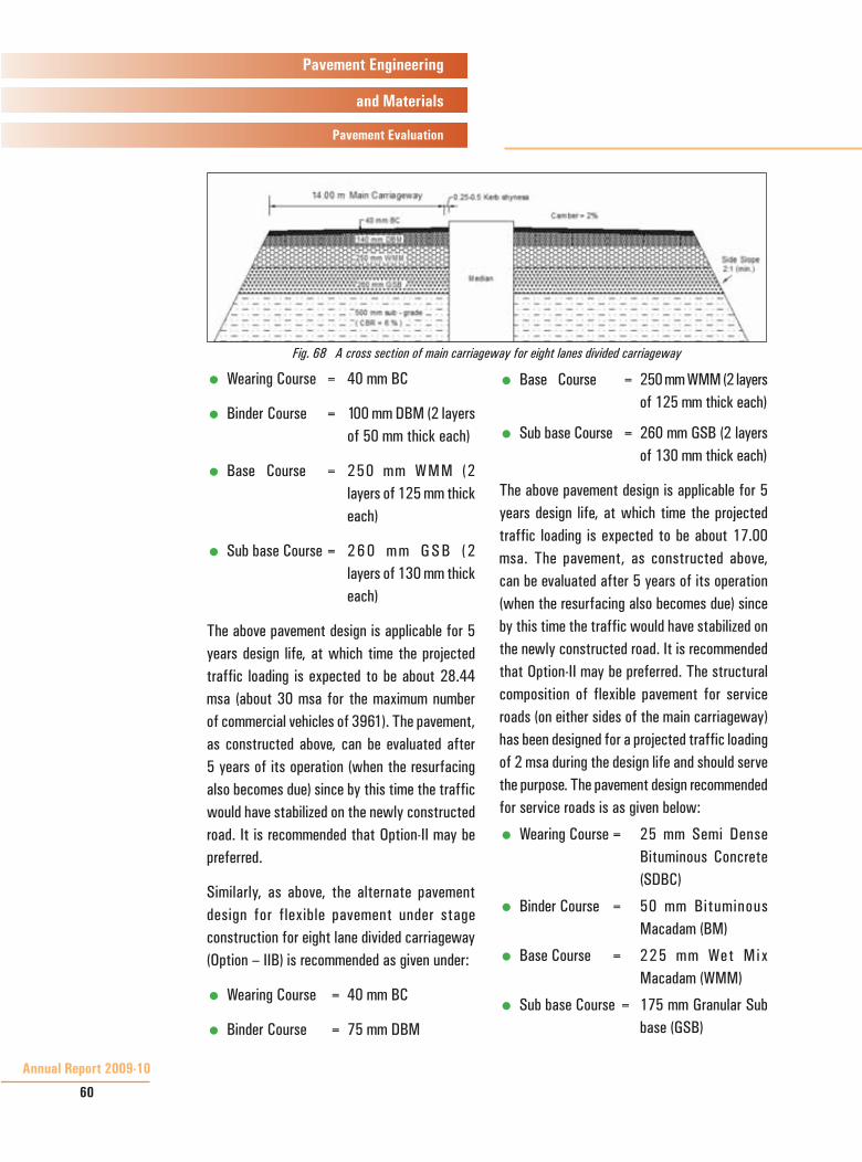
Fig. 67 & 68 show the cross section of main carriageway for four lane and eight lane divided carriageway. Keeping in view the gross uncertainties with regard to the extent of traffic and axle loading likely to use the new road which will be diverted / generated and also the proposed future plans for development of new roads and upgradation / connectivity / expansion plans for existing roads in the project area, the alternate pavement design for flexible pavement under stage construction for four lane divided carriageway (Option – IIA) is also recommended as given below:
Fig. 67 A cross section of main carriageway for four lanes divided carriageway
Annual Report 2009-10
60
Pavement Engineering
and Materials
Pavement Evaluation
� Wearing Course = 40 mm BC
� Binder Course = 100 mm DBM (2 layers of 50 mm thick each)
� Base Course = 250 mm WMM (2 layers of 125 mm thick each)
� Sub base Course = 2 6 0 m m G S B ( 2 layers of 130 mm thick each)
The above pavement design is applicable for 5 years design life, at which time the projected traffic loading is expected to be about 28.44 msa (about 30 msa for the maximum number of commercial vehicles of 3961). The pavement, as constructed above, can be evaluated after 5 years of its operation (when the resurfacing also becomes due) since by this time the traffic would have stabilized on the newly constructed road. It is recommended that Option-II may be preferred.
Similarly, as above, the alternate pavement design for flexible pavement under stage construction for eight lane divided carriageway (Option – IIB) is recommended as given under:
� Wearing Course = 40 mm BC
� Binder Course = 75 mm DBM
� Base Course = 250 mm WMM (2 layers of 125 mm thick each)
� Sub base Course = 260 mm GSB (2 layers of 130 mm thick each)
The above pavement design is applicable for 5 years design life, at which time the projected traffic loading is expected to be about 17.00 msa. The pavement, as constructed above, can be evaluated after 5 years of its operation (when the resurfacing also becomes due) since by this time the traffic would have stabilized on the newly constructed road. It is recommended that Option-II may be preferred. The structural composition of flexible pavement for service roads (on either sides of the main carriageway) has been designed for a projected traffic loading of 2 msa during the design life and should serve the purpose. The pavement design recommended for service roads is as given below:
� Wearing Course = 25 mm Semi Dense Bituminous Concrete (SDBC)
� Binder Course = 50 mm Bituminous Macadam (BM)
� Base Course = 225 mm Wet Mix Macadam (WMM)
� Sub base Course = 175 mm Granular Sub base (GSB)
Fig. 68 A cross section of main carriageway for eight lanes divided carriageway

CRRI New Delhi
61
Pavement Engineering
and Materials
Pavement Evaluation
Traffic Counts and Axle Loads Survey on Azamgarh-Mau-Phephna Road for Determination of Vehicle Damage Factor
At the instance of Chief Engineer, World Bank Projects (Roads), Uttar Pradesh Public Works Department, Lucknow, this study was carried out primarily to determine (i) Average Daily Traffic (ADT) based on 7 days traffic survey, (ii) Vehicle Damage Factors (VDFs) for different types of commercial vehicles, and (iii) Cumulative Numbers of Standard Axles (CSALs) passing over the road section of Azamgarh-Mau-Phephna. Duration of axle loads and traffic counts survey at one location was kept as 4 days and 7 days (24X7) respectively, round the clock, covering both directions of travel. Portable and non-embedded type wheel weighing pads were used for recording of axle loads. Fig. 69 shows the arrangement for weighing commercial vehicles.
Based on the data collected and results obtained through traffic volume surveys and axle loads spectrum study, conducted at one location, on Azamgarh-Mau-Phephna road continuously for 7 days and 4 days respectively, the following major conclusions were drawn:
� A total of 13898 commercial vehicles (both heavy and light) were counted during the period of traffic survey (i.e. 168 hours round the clock for 7 days) in up and down directions. The average daily traffic (ADT) in terms of commercial vehicles per day calculated based on 7 days traffic counts data, is found to be 1985.
� A total of 6542 commercial vehicles (both heavy and light) were counted during the period of traffic survey (i.e. 168 hours round the clock for 7 days) in up direction (towards Dhorighat). A total of 3585 commercial vehicles (both heavy and light) were counted during the period of axle loads survey (i.e. Day1, Day 3, Day 5 and Day 7 round the clock) out of which
Fig. 69 Front wheel of a 2 - axle truck being weighed using non-embedded type wheel weighing pads

Annual Report 2009-10
62
Pavement Engineering
and Materials
Pavement Evaluation
2445 commercial vehicles were weighed which is 68.20 per cent. The overall VDF for the road in up direction is found to be 35.93
� A total of 7356 commercial vehicles (both heavy and light) were counted during the period of traffic survey (i.e. 168 hours round the clock for 7 days) in down direction (towards Azamgarh). A total of 4092 commercial vehicles (both heavy and light) were counted during the period of axle loads survey (i.e. Day1, Day 3, Day 5 and Day 7 round the clock) out of which 2222 commercial vehicles were weighed which is 54.30 per cent. The overall VDF for the road in down direction is found to be 1.69.
� The cumulative numbers of standard axles are 203 and 224 million standard axles (msa) during a design life of 8 years at growth rates of 7.5 percent and 10 percent per annum respectively.
� It was noticed during the period of surveys that large scale road construction activities are currently in progress towards Gorakhpur. Substantial numbers of overloaded trucks, transporting the construction materials, were found to be using the project road which may be temporary or seasonal. The extent of overloading by trucks, in up direction, carrying construction materials are abnormal and beyond imagination. However, these overloaded trucks/dumpers have significantly influenced the loading
scenario and have contributed heavily to the increase in value of VDF and deterioration of road. Most of these trucks, on the other hand, were found either emptied or lightly loaded while returning to Azamgarh, leading to a wide difference in the values of VDF between the two directions of travel.
� Overloading affects significantly the pavement’s service life and leads to pre-mature failure/distress of the road. It is, therefore, suggested that stringent measures may be taken by enforcement authority to control and /o r m in im i ze the excess i ve overloading by trucks, particularly vehicles carrying construction materials towards Gorakhpur in order to (i) ensure desired level of pavement performance / serviceability within the design period, (ii) avoid the risk of pre-mature distress / failure, and (iii) minimize maintenance and rehabilitation costs and road user costs.
Evaluation of Serviceability of Pavement Surface of Eastern and Western Express Highways in Mumbai Region
This assignment was referred by Mumbai Construction Circle, P.W.D. Mumbai to evaluate the serviceability or functional quality in terms of riding quality (roughness) and surface friction characteristics of the Eastern and Western Express Highways from traffic safety point of view in Mumbai region.
CRRI New Delhi
63
Pavement Engineering
and Materials
Pavement Evaluation
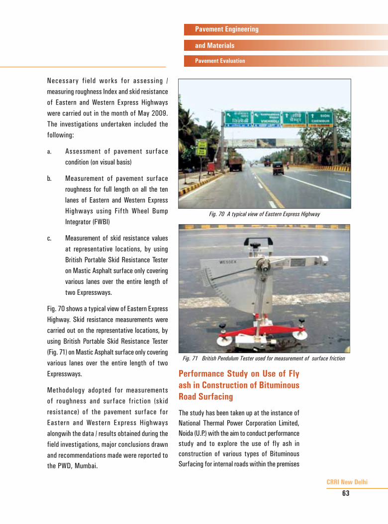
Necessary f ield works for assessing / measuring roughness Index and skid resistance of Eastern and Western Express Highways were carried out in the month of May 2009. The investigations undertaken included the following:
a. Assessment of pavement surface condition (on visual basis)
b. Measurement of pavement surface roughness for full length on all the ten lanes of Eastern and Western Express Highways using Fifth Wheel Bump Integrator (FWBI)
c. Measurement of skid resistance values at representative locations, by using British Portable Skid Resistance Tester on Mastic Asphalt surface only covering various lanes over the entire length of two Expressways.
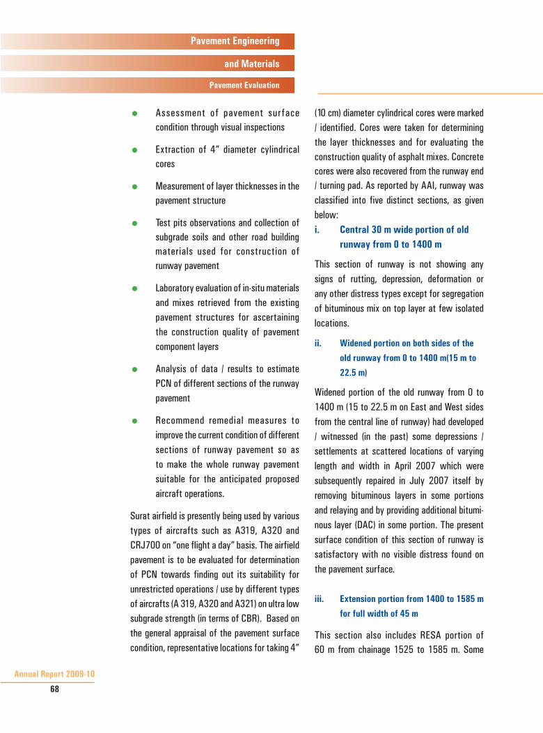
Fig. 70 shows a typical view of Eastern Express Highway. Skid resistance measurements were carried out on the representative locations, by using British Portable Skid Resistance Tester (Fig. 71) on Mastic Asphalt surface only covering various lanes over the entire length of two Expressways.
Methodology adopted for measurements of roughness and surface friction (skid resistance) of the pavement surface for Eastern and Western Express Highways alongwih the data / results obtained during the field investigations, major conclusions drawn and recommendations made were reported to the PWD, Mumbai.
Performance Study on Use of Fly ash in Construction of Bituminous Road Surfacing
The study has been taken up at the instance of National Thermal Power Corporation Limited, Noida (U.P.) with the aim to conduct performance study and to explore the use of fly ash in construction of various types of Bituminous Surfacing for internal roads within the premises
Fig. 71 British Pendulum Tester used for measurement of surface friction
Fig. 70 A typical view of Eastern Express Highway

Annual Report 2009-10
64
Pavement Engineering
and Materials
Pavement Evaluation
of NTPC plants located in Dadri and Badarpur including rehabilitation / strengthening.
Field visits and inspection of various roads in the plant areas (NTPC-Dadri and Badarpur Campus) were made in order to have physical assessment of the roads which have to be rehabilitated / strengthened / resurfaced within NTPC Dadri plant campus and to appraise the current condition of project roads. Subsequently, detailed investigations / surveys related to the pavement evaluation on the identified project roads which needed maintenance / rehabilitation were also undertaken.
The primary objective of the R&D study is to evaluate performance of road sections constructed with different types of bituminous surfacings constructed by using fly ash as mineral filler vis-a-vis constructed in a conventional way (by using lime as mineral filler).
The scope of work of the study included
1. Pavement condition survey before construction, materials and construction
specifications, preparation of BOQs, job mix designs, and limited construction quality checking / supervision of road sections. .
2. Association during laying of demonstration stretches for use of fly ash in Bituminous Concrete (BC), Stone Matrix Asphalt (SMA) and Slurry Seal / Micro-Surfacing.
3. To develop periodic pavement performance data (such as deflection, roughness, surface distress, traffic volume etc.) at six months interval for a period of 3 years.
The road length considered under this study in Dadri is about 5414 meter having variations in pavement width from 3 to 7 meter. The details of road length of project roads are presented in Table VII.
Detailed investigations (structural and functional evaluation) were undertaken on the project roads with a view to assess the condition of existing pavements. Tasks / activities included
Table VII Details of Length and Width of Project Roads in the Study Area
S. No.
Link / Road Name Length (m)
Width (m)
Total Road Length (m)
Traffic Category (in terms of CVs*)
1 Gate No. 3 to T- Junction 964 7 964 High
2 T-Junction to Paschi ViharPaschi Vihar to Culvert (near Paschi Vihar) Culvert to Entry Gate of Ash mound Control Room to T-Junction
166
3116
1168
3
7
7
4450 Nil / Insignificant
Nil / Insignificant
Medium
TOTAL ROAD LENGTH 5414
* CVs – Commercial Vehicles in terms of 2-axle and multi-axle trucks

CRRI New Delhi
65
Pavement Engineering
and Materials
Pavement Evaluation
assessment of pavement surface condition (visual basis), roughness measurements, Benkelman Beam deflection measurements, traffic volume surveys (only commercial vehicles) and test pit observations
The major types of surface distress recorded in terms of percentage of the total pavement’s surface area are cracking, ravelling, pot holes, shoving, bleeding, corrugation and rutting etc. The structural inadequacy of pavement is worked out by using characteristic deflection values and cumulative number of standard axles. Using average characteristic deflection data (average of all the roads / links) and projected traffic loading (msa), the overlay thicknesses have been worked out for different project roads in terms of Bituminous Macadam (BM) for 10 years design life as per IRC: 81- 1997. The overlays required for different project roads are given in Table VIII.
Table shows that the existing roads / links are structurally adequate for a design period of 10
years. On the other hand, pavement surface roughness for these roads indicates that these roads are in poor condition. Hence, in order to improve the current condition of project roads / links from their functional point of view and to provide comfortable ride to the users, renewal / resurfacing treatments in terms of 40 mm thick Bituminous Overlay is recommended. Table IX shows the proposed specifications on various sections of different project roads, which are to be constructed using lime and fly ash as the mineral filler.
Design of Pavement around Rotary Junction 26 between Sectors 16 to 17 and 22 to 23 at Chandigarh
The rotary (Junction No. 26) i.e. between Sectors 16 to 17 and 22 to 23 is a very busy roundabout, which is located very close to Interstate Bus Terminus (ISBT). This rotary caters to a very large number of mixed types of vehicles consisting of two-wheelers, cars, three wheelers, buses and commercial
Table VIII Overlay Thickness Required for Different Project Roads (Design Life=10 Years)
Direction Traffic (CVPD)
VDFAverage
Characteristic Deflection (mm)
Design Traffic (msa)
Overlay Requirements (BM), in mm
Gate No. 3 to T-Junction495 4.5
0.82
10 Nil
T-Junction to Ash mound 248 4.5 5 Nil
Ash mound to Paschi Vihar Nil 4.5 2 Nil
Notes: CVPD = Commercial Vehicles per Day; VDF= Vehicle Damage Factor; MSA = Million Standard Axles ; BM= Bituminous Macadam

Annual Report 2009-10
66
Pavement Engineering
and Materials
Pavement Evaluation
vehicles (Fig. 72) entering into / leaving Chandigarh from / to different places / states. Due to the frequent movement of large number of heavy vehicles (particularly buses) using this roundabout, extensive severe cracks and large settlements have occurred on the existing pavement surface (Mastic Asphalt), particularly in the innermost lane which was laid about 6 to 7 years back.
Keeping in view the frequent problems being faced by the Administration with regard to the upkeep and maintenance of Mastic Asphalt surface,
Table IX Recommended Specifications to be laid on Project Roads / LinksS. No. Road Section Proposed Specifications Road Length (m)
1.Gate No. 3 to T-Junction
40 mm thick SMA (with Lime as Filler) 241
40 mm thick SMA (with Fly Ash as Filler) 241
40 mm thick BC (with Lime as Filler) 241
40 mm thick BC (with Fly Ash as Filler) 241
2. T-Junction to Paschi Vihar (Total Length of 4450 m) excluding the proposed 1300 m length of Concrete Pavement which is from Control Room to Entry Gate of Ash mound
S. No. Road Section Proposed Specifications Road Length (m)
a)
T-Junction to Control Room (~1168 m in length)
40 mm thick BC (with Lime as Filler) 292
40 mm thick BC (with Fly Ash as Filler) 292
40 mm thick SMA (with Lime as Filler) 292
40 mm thick SMA (with Fly Ash as Filler) 292
b)
Entry Gate of Ash mound to Culvert near Paschi Vihar (~4416 m in length)
40 mm thick BC (with Lime as Filler) 620
40 mm thick BC (with both Lime and Fly Ash as Fillers in 50:50 Proportion)
620
40 mm thick BC (with Fly Ash as Filler) 620
40 mm thick SMA (with Lime as Filler) 628
40 mm thick SMA (with Fly Ash as Filler) 628
c) Culvert to Paschi Vihar
40 mm thick BC (with Fly Ash as Filler) 166
Notes : BC= Bituminous Concrete ; SMA= Stone Matrix Asphalt
Fig. 72 A typical view of vehicular movements around Rotary Jn. 26

CRRI New Delhi
67
Pavement Engineering
and Materials
Pavement Evaluation
the Chief Engineer, Union Territory-Chandigarh Administration, requested the Institute to take up an assignment with the objectives to suggest pavement design and materials / construction specifications bituminous layers and using concrete paver blocks alternatively.
Field visits / inspection of Rotary Junction 26 were made to appraise the site conditions. Based on the inspection of rotary, following recommendations on pavement designs were given.
Recommended Rehabilitation Design with Bituminous Layers (Option-I) The recommended rehabilitation treatments which will be laid over the existing bituminous pavement after milling / scarifying the existing mastic asphalt surface included.
a. Mastic Asphalt 40 mm
b. Dense Bituminous 50 mm Macadam (DBM)
Recommended Rehabilitation Design with Concrete Paver Blocks (Option-II)
a. Thickness of Concrete 100 mm Paver Blocks
b. Strength of Concrete M-55 Paver Blocks (Specified (55 MPa) Compressive Strength of Paver Blocks at 28 Days)
c. Bedding Sand 30 – 40 mm
d. Dry Lean Concrete (DLC) 150 mm (Specified Compressive M-10 Strength at 28 days) (10 MPa)
The typical laying pattern of concrete paver blocks at Rotary Jn. 26. is shown in Fig. 73.
Determination of Pavement Classification Number (PCN) and Suitability of Existing Runway for use at Surat Airport
This assignment was sponsored by Surat Airport Project, Airports Authority of India (AAI), Surat with the aim to determine the load carrying capacity in terms of Pavement Classification Number (PCN) for different portions / sections of the existing runway pavement at Surat Airport and to evaluate the quality of different sections of the runway pavement with regard to their use by different aircrafts currently operating and for the projected aircraft operations.
The scope of work includes the following major activities / tasks:
� Measurement of pavement deflections on different sections of the runway, at pre-determined loads, by using Falling Weight Deflectometer (FWD)
Fig. 73 Typical laying pattern of concrete paver blocks at Rotary Jn. 26.
Annual Report 2009-10
68
Pavement Engineering
and Materials
Pavement Evaluation
� Assessment of pavement surface condition through visual inspections
� Extraction of 4” diameter cylindrical cores
� Measurement of layer thicknesses in the pavement structure
� Test pits observations and collection of subgrade soils and other road building materials used for construction of runway pavement
� Laboratory evaluation of in-situ materials and mixes retrieved from the existing pavement structures for ascertaining the construction quality of pavement component layers
� Analysis of data / results to estimate PCN of different sections of the runway pavement
� Recommend remedial measures to improve the current condition of different sections of runway pavement so as to make the whole runway pavement suitable for the anticipated proposed aircraft operations.
Surat airfield is presently being used by various types of aircrafts such as A319, A320 and CRJ700 on “one flight a day” basis. The airfield pavement is to be evaluated for determination of PCN towards finding out its suitability for unrestricted operations / use by different types of aircrafts (A 319, A320 and A321) on ultra low subgrade strength (in terms of CBR). Based on the general appraisal of the pavement surface condition, representative locations for taking 4”
(10 cm) diameter cylindrical cores were marked / identified. Cores were taken for determining the layer thicknesses and for evaluating the construction quality of asphalt mixes. Concrete cores were also recovered from the runway end / turning pad. As reported by AAI, runway was classified into five distinct sections, as given below:
Central 30 m wide portion of old i. runway from 0 to 1400 m
This section of runway is not showing any signs of rutting, depression, deformation or any other distress types except for segregation of bituminous mix on top layer at few isolated locations.
Widened portion on both sides of the ii.
old runway from 0 to 1400 m(15 m to
22.5 m)
Widened portion of the old runway from 0 to 1400 m (15 to 22.5 m on East and West sides from the central line of runway) had developed / witnessed (in the past) some depressions / settlements at scattered locations of varying length and width in April 2007 which were subsequently repaired in July 2007 itself by removing bituminous layers in some portions and relaying and by providing additional bitumi-nous layer (DAC) in some portion. The present surface condition of this section of runway is satisfactory with no visible distress found on the pavement surface.
Extension portion from 1400 to 1585 m iii.
for full width of 45 m
This section also includes RESA portion of 60 m from chainage 1525 to 1585 m. Some

CRRI New Delhi
69
Pavement Engineering
and Materials
Pavement Evaluation
settlements / depressions on this portion of runway, specifically on the wheel tracks (4 to 4.5 m wide strips on both sides from the central line), were observed sometimes after the runway was put to operation. Overlays of bituminous layers (30 to 50 mm DAC) were then provided twice on this section, first time during July, 2007 and during January, 2008 due to development of deformation / rutting, especially along the wheel paths (about 4 to 5 m from the central line on both sides).
Extension portion from 1585 to 2094 m iv. for full width of 45 m
This section of runway presently neither has any signs of depression or any other distress nor is reported to have developed any distress in the past.
Rigid turning pad and Dumbbell from v. chainage 2094 to 2250 m at End 22
The most common type of distress found on this portion was surface cracking in the centre of slabs. Such cracks were however epoxy repaired by AAI. Two to three slabs were found to be having wide cracking.
Pavement deflection measurements, by using FWD, were undertaken on runway pavement and rigid ends at Surat Airport. The FWD system was applied on several sections of the airfield pavement with known cross sectional details obtained from the records / test pits. Pavement deflection measurements by FWD were undertaken on the main runway at an interval of about 50 meter in staggered position and largely on the most used portion of runway on both sides of the centre line. Similarly, FWD deflection measurements were taken on runway ends / turning pads also at representative locations well spread over the paved area.
Fig. 74 shows FWD being used for taking deflection measurements on the runway.
Based on the field and laboratory investigations, carried out on different sections of the runway pavement, the following major findings emanated:
CBR of subgrade soil is found to be less 1. than 2; and therefore it is categorized in ‘ultra low’ category as per ICAO guide-lines for PCN evaluation.
Typical distress types found on the rigid 2. runway End 22 include edge cracking, corner cracking and full width crack-ing, all in the longitudinal and transverse directions, on a considerable number of slabs.
The values of PCN determined for differ-3. ent sections of the runway pavement, viz. (i) original portion of the old runway at 04 End from 0 to 1400 m (30m wide), (ii) widened portion of the old runway from 30 to 45 m, (iii) Extended portion of runway from 1400 to 1585 m (45 m wide), (iv) Extended portion of runway from 1585 m to 2094 m (45 m wide),
Fig. 74 Deflection measurements using FWD on runway at Surat Airport

Annual Report 2009-10
70
Pavement Engineering
and Materials
Pavement Evaluation
and (v) Rigid turning pad at 22 End from 2094 to 2250 m including dumbbell, are 80/F/D/W/T, 36/F/D/W/T, 27/F/D/W/T, 22/F/D/W/T and 70/R/D/W/T respec-tively.
Problematic areas 4. / locations assessed during the evaluation of runway pave-ment include extended portion of the runway pavement from 1400 to 1585 m (45 m wide). This section of runway is recommended to be reconstructed for a design PCN value of 63 on the existing ‘Ultra Low’ subgrade strength, as per AAI / ICAO design guidelines.
Widened portion of original runway from 5. 0 to 1400 m (30 to 45 m) and the ex-tended section of runway pavement from 1595 to 2094 m, are recommend-ed to be strengthened / overlaid with the following specifications:
Widened portion of old runway a) on both sides (30 to 45 m) Provide bituminous overlay of 125 mm thick (75 mm DBM + 50 mm BC)
Extended portion of runway b) pavement (1585 to 2094 m) Provide bituminous overlay of 200 mm thick (2x75 mm DBM +50 mm BC)
Evaluation of Master Plan Road No.1 and Udyog Marg in Noida
The assignment was taken up at the request of New Okhla Industrial Development Authority (NOIDA) to carry out detailed investigations of the two roads i.e. Master Plan Road No. 1
(MP-1 Road) and Udyog Marg in Noida towards determining the likely causes of distress/ defects developed on these roads and to suggest remedial measures needed to overcome the problem (s).
The scope of work included the following major activities:
a. Field investigations
� Functional evaluation of pavement surface through roughness measurements, us ing du ly calibrated fifth wheel bump integrator, on each lanes of both carriageways for the entire length of project roads
� Assessment of pavement surface distress (types and extent) by visual observations.
� Structural evaluation of pavement by Benkelman Beam deflection measurements (11 points per Km in each carriageway), covering the entire length of project roads
� Test pits evaluation (about 2 to 3 on each of the two roads, representing variations in surface condition)
� Classified traffic volume surveys at one location for 24 hours round the clock on each road
b. Laboratory evaluation by determining the engineering properties of materials retrieved from different layers of the existing pavement structures of two roads.

CRRI New Delhi
71
Pavement Engineering
and Materials
Pavement Evaluation
The type of surface distress is mainly cracking, patching / potholes and slippage occurring mostly on Mastic Asphalt surface at the intersections. Also, undulations/ settlements were observed on the road in few places which are also affecting the riding quality. The extent of distress found on Udyog Marg in both directions of road was more than MP-1 Road (Figs. 75,76,77 & 78).
The major findings, based on the data/results, are summarized as under:
i. The total surface distress on Udyog Marg is maximum 45 to 50 percent while it is maximum 25 to 30 percent on MP-1 Road. The major types of surface distress/defects developed on the project roads are cracking, potholes, patching and raveling.
ii. Deflection values clearly indicate that the existing pavements are deficient with regard to their structural adequacy for the prevailing and projected traffic volume and loads.
iii. Based on the characteristic deflections data and cumulative number of standard axles worked out for the project roads, it becomes very clear that the existing roads are structurally inadequate and would not be able to cope up with the expected traffic loads. Consequently, the roads are in dire need of immediate rehabilitation/ strengthening to augment their structural capacity so as to improve their load carrying/ bearing capacity.
Following are the major likely causes which may be responsible for development of distress/
Fig.75 Extensive alligator cracking on MP-1 road
Fig. 76 Slippage at the intersection on MP-1 road
Fig. 77 A typical view of distress on Udyog marg
Fig. 78 Patching, potholes and loss of materials on Udyog marg

Annual Report 2009-10
72
Pavement Engineering
and Materials
Pavement Evaluation
defects on the pavement surfaces of two roads:
� Inadequate structural capacity of the existing pavements in regard to the current and projected traffic loading, the project roads are subjected to.
� Higher volume of commercial vehicles using the roads and the overloading being caused by them.
� A p p l i c a t i o n o f B M + B C combination is not at all a good practice, particularly for heavily trafficked roads like the two project roads. This combination should not be used due to a number of factors which have been very emphatically brought out earlier by CRRI. The preferred combination is DBM+BC.
� Use of soling (large sized stones/boulders) and/or WBM Gr. I material in the subbase layer may be one of the contributing factors responsible for deterioration of project roads. This specification has completely been discarded/ omitted for a long time by many road departments. This layer does not offer much strength to the pavement structure and also does not provide enough support to the overlying pavement layers because of weak interlocking and large voids therein.
� No Granular Subbase (GSB) layer/ material have been used in the pavement structures. This layer works as a drainage layer and facilitates movement/flow of water entrapped within the pavement structure. Absence of GSB layer might also have contributed for the deterioration of project roads.
� Since the type of subgrade soil used on project roads has significant proportion of clay, the provision of GSB becomes absolutely essential under such situations. Due to the absence of GSB layer, the water entering into the subgrade weakens its strength due to the volume change and plastic deformation. As can be seen, the field moisture contents in two out of the four test pits (pit number 1 and 3 which have clayey soils) are more than the optimum moisture content which substantiates the point highlighted above.
� In summary, reduced compaction levels of the subgrade layer, use of stone soling in the subbase, and absence of GSB layer in the pavement structure, have probably been responsible for deterioration of project roads.
� Slippage of mastic asphalt observed at some sections on the intersections might have occurred

CRRI New Delhi
73
Pavement Engineering
and Materials
Pavement Evaluation
due to improper workmanship, inferior quality of constituent materials, inadequate job mix design and incorrect laying process etc. Mastic asphalt may be relaid as per specifications laid down in Section 500 (Item No. 515) of MORTH specifications.
� The life of Bituminous Concrete (BC) surfac ing on heav i ly trafficked roads is generally about 4 to 5 years which has outlived its life since the resurfacing was done on project roads about 4 to 5 years back (in 2004). The life of surfacing gets further reduced if it is laid on a weak pavement structure which is the present case.
The project roads are distressed due to inadequate structural strength of the existing pavements for the present day and projected traffic loads. Thus, the existing pavement structures need strengthening / rehabilitation. The rehabilitation of roads may be undertaken by applying appropriate treatments in terms of overlay with bituminous layers, as recommended. As regards rectification of distress developed on the intersections, it is recommended that 40mm thick mastic asphalt layer may be provided at these locations. Dense Bituminous Macadam shall be prepared by using 60/70 penetration grade paving bitumen, while Bituminous Concrete shall preferably be prepared by using modified bitumen, conforming to IRC: SP: 53-2002. In Bituminous Concrete and Dense Bituminous Macadam, lime stone dust or lime having 85 per
cent material passing through 75 micron sieve shall be used as the filler material.
Investigation to Determine and Ascertain Causes of Distress and Suggest Remedial Measures for the Runway Pavement at Jaipur Airport
This assignment was taken up at the request of Airports Authority of India, New Delhi with the prime objective to investigate and ascertain causes of distress and suggest remedial measures for the runway pavement at Jaipur Airport.
The main runway pavement at Jaipur Airport consists of flexible and rigid portions. The flexible portion of the runway pavement is 1823 m long and 45 m wide with 7.5 m paved shoulders on both sides of the pavement. Rigid portion of the runway is 914 m long and 60 m wide. The taxi track and apron areas are partly flexible and partly rigid pavements construction. The flexible portion of the main runway has a declared PCN value of 58/F/B/W/T while rigid portion of the main runway has declared PCN value of 57/R/B/W/T. Surface texture of the pavements can be rated as coarse / rough.
Jaipur airfield is presently being used by several types of aircrafts and deemed suitable for B767 class of aircraft operations under IMC. The airfield pavement is required to be evaluated towards determining and ascertaining the likely causes of distress and subsequently suggest remedial measures for improvement of the runway. The airfield pavements are also planned to be upgraded in future in order to

Annual Report 2009-10
74
Pavement Engineering
and Materials
Pavement Evaluation
receive heavier types of aircrafts for its future operation.
Necessary field works / investigations undertaken for the evaluation of existing runway pavement included assessment of surface condition of the runway pavement by visual inspection. It was observed that there was no visible distress in the first 600 metres length of the runway except that the pavement surface was hungry. Pavement was found to be distressed mainly from 600 to 1020 m along and across the centre line on most used lanes. Distresses observed from 600 to 1020 m on the main runway are in the form of oozing of water, in the form of patches on the surface, cracking, raveling, deformation, patch work, and pot holes.
Major ity of the locations were highly distressed / badly cracked. This has primarily occurred probably due to entrapment of water in the lower bituminous layers. Similar kind of distresses were observed on stretch from 1020 to 1200 m. Stretch from 1200 to 1800 m was found to be hungry surface with some patches due to oozing of water on the surface. Vegetation growth was also seen at very few locations on the shoulders. Drainage and shoulder conditions of the runway were found to be in fair to poor condition.
Based on the general appraisal of pavement surface condition, representative locations for taking 4” (10 cm) and 6” (15 cm) diameter cylindrical cores were taken over the entire length of runway for determining the layer thicknesses and for evaluating the construction quality etc. A total of 26 bituminous cores were recovered from the
runway pavement, which was then tested in the laboratory for their properties.
Four test pits, one on sound condition of the pavement and three on problematic areas of the runway, of size 1.25 x 1.25m, on / near the edge of the pavement were cut open for determination of thickness of component layers and field density etc. Road construction materials from different component layers in the pavement structure were also collected for laboratory evaluation.
Further analysis of data and report prepara-tion is in progress.
S t a t e - o f - A r t E q u i p m e n t s /Facilities Created
Network Survey Vehicle System
The Network Survey Vehicle (NSV) system is based on the latest survey techniques utilizing Laser, Global Positioning System and Video image processing tools etc (Fig. 79). The Survey Vehicle is being used for automatic collection of road condition related data for National Highways. The inventory data collected include measurement of gradient (rise and fall), horizontal curvature, pavement surface condition (distress), roughness, and GPS coordinates (X, Y, Z) viz. longitude, latitude & altitude etc. Based on the information collected through NSV and using the map data, a user friendly GIS based interactive system is currently under development.
Key Features of the Network Survey Vehicle System are:
a. High survey speed up to 100 km/hr

CRRI New Delhi
75
Pavement Engineering
and Materials
Pavement Evaluation
b. Longitudinal (International Roughness Index) and transverse profiling (Rut Depth) conforms to ASTM standards
c. Pavement Texture in terms of Mean Profile Depth
d. Slope, Cross-fall, Radius of curvature
e. GPS coordinates (X, Y, Z) viz. longitude, latitude & altitude using DGPS
f. Video imaging for
� Roadside furniture / Road asset
g. Advanced data processing and reporting software
� Rea l t ime in -veh ic le data acquisition software for display and collection of data from all parameters simultaneously
� Post processing software for data analysis and report preparation
h. It is Windows XP based
Roughometer-IIRoughometer-II is a high speed device used for measuring pavement surface roughness. It
Fig. 79 Network Survey Vehicle (NSV)
Fig. 80 Roughometer –II
is portable type equipment and consists of a small accelerometer (sensor) device installed at the rear axle of survey vehicle, a distance measuring instrument, interface module and a controller (Fig. 80). The pavement roughness measurements using this equipment are required to be done preferably at a speed in between 40 to 60 km/hr, in order to obtain most reliable and accurate data. The output is in the units of International Roughness Index (IRI).

Annual Report 2009-10
76
Pavement Engineering
and Materials
Pavement Evaluation
Walking Profiler
The Walking Profiler is a precision instrument designed to collect surface profile data (Fig. 81). The data can be used to accurately assess the characteristics and quality of any continuous paved surface. Typically the surface profile is used to generate a number of internationally recognized roughnesses, ride quality and pavement maintenance indices etc.
It is designed to operate at a moderate and steady walking pace in a straight line. The equipment has an integral Control Unit which provides all the functions of instrument calibration, survey setup and operator feedback. Like Dipstick, it also directly gives International Roughness Index in m/km.
Fig. 81 Walking Profiler