Brussels, 3 March 2005 Any content, Any platform, Any time, Anywhere.

ARE YOU READY TO
-OWNER’S MANUAL-
Modular floating systems
Anchoring
www.candock.com [email protected]
9441, Bourque Blvd.Sherbrooke (Qc) J1N 0G2
OFFICE|BUR. T.FREE|S. FRAIS FAX|TÉLÉC.
819 847-25991 888 547-2599
819 847-3250

Modular floating systems
www.candock.com [email protected]
9441, Bourque Blvd.Sherbrooke (Qc) J1N 0G2
OFFICE|BUR. T.FREE|S. FRAIS FAX|TÉLÉC.
819 847-25991 888 547-2599
819 847-3250
TABLE OF CONTENT
G2 “POST CUBE” DISPOSITION ( low profile and regular )
2 7/8 “ STEEL PILE INSTALLATION ( galvanized or staineless steel )
3 1/2 ” PVC PIPE AND CAP
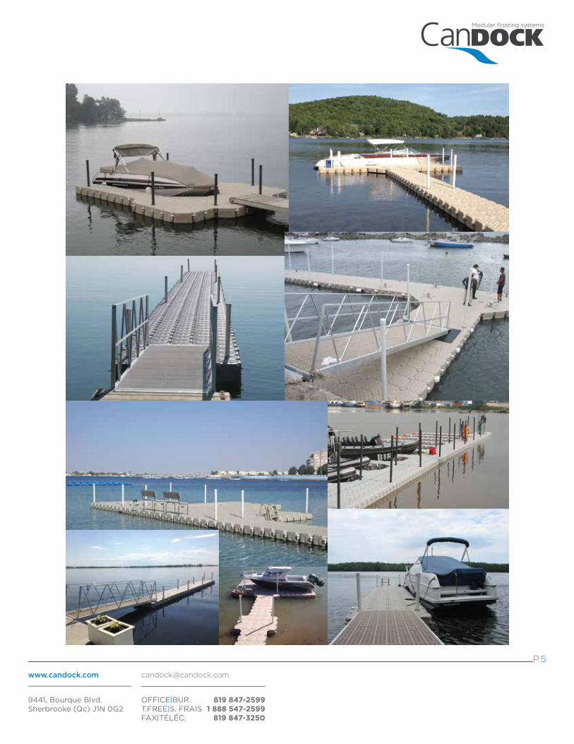
IMAGES
PILLING GUIDE (6” to 15” inches diameter )
P.2
P.3
P.4
P.5
P.6
*The following instructions are guidelines to be followed. Candock will not be responsible for damages incured by the non-compliance to these guide lines. All distributors are required and responsible to provide theoretical and practical training to clients on the completeuse of the different dock systems. Candock inc. can not be held responsible in any way for any damages resulting from the fact that the client has not received adequate training.
P.1
ANCHORING PLATE FOR CHAIN
CHAIN ADJUSTER
EXTERIOR ANCHORING RING FOR CHAIN ( regular or H.D. )
G2 CONNECTING PIN FOR ANCHORING
CHAIN ( 3/8 “ or 5/16 ” gages, galvanised or staineless steel )
TMS ( TIDE MANAGEMENT SYSTEM )
CONFIGURATION GUIDE LINES AND TIPS
P.7
P.7
P.8
P.8
P.9
P.9
P.10
ANCHORING STRUTS ( aluminum or staineless steel ) P.11
DOCK LEG SUPPORT
WALL ANCHORAGES (painted steel or stainless steel )
SPECIFIC HARDWARE FOR CONCRETE
P.13
P.13
P.14
ANCHORING METHODS RELATED PRODUCTS
PILINGS
UNDER WATER ANCHOR POINTS
WITH ANCHOR LINES
ANCHORING STRUTS
MISCELLANEOUS
*** Note that it is preferable to consult the manual on a COLORED printed version, or directly on your computer screen***

See regular G2 CUBE assembly procedure as for the G2 POST CUBE installation while abiding to these rules:
The pilings are mainly used in shallow water conditions ( MAX 2 meters ). Needing soft or muddy sea bottoms, pilings are mainly used on shore lines where the soil is soft and tractable. If the evironment is filled with rocks or other solid debris, other methods should be prefered to anchor your CANDOCK dock. An important aspect of the piling method consists in keeping the piles perfectly vertical. Using a level or other precision tools is mandatory for every pile. If the sea bottom is made of clay, be careful not to penetrate the soil too deep as a suction effect will make the removal of those pilings practically impossible. Another important notion, never use pilings in agitated water ( maximum waves 0.6 meter / 2 feet ). Furthermore, pilings should not be used in areasthat are consisting of loose soils and that are exposed to waves as the pilings maybe pulled out of the ground by wave action.
G2 POST CUBES DISPOSITION
-Maximum 7 to 9 meters between each post cubes. ( ideally 13-14 cubes )
Modular floating systems
www.candock.com [email protected]
9441, Bourque Blvd.Sherbrooke (Qc) J1N 0G2
OFFICE|BUR. T.FREE|S. FRAIS FAX|TÉLÉC.
819 847-25991 888 547-2599
819 847-3250
P.2
G2 POST CUBE
ASSEMBLY PROCEDURE
Material/Composition :High-density polyethylene resinInterior filled with expanded polystyrene
Surface :Anti-skid
Dimensions :L x W : 48 cm (19”) x 48 cm (19”)H : 36 cm (14”)
Dimensions (low profile cube) :L x W : 48 cm (19”) x 48 cm (19”)H : 23 cm (9”)
Weight :Cube: 9.55 kg (21 lbs.)Low profile cube : 7.5 kg (16.5 lbs.)
Needed tools :G2 key for pin “combo-pack”Key for nutorRatchet key for nut + ratchet toolPiling bull 2 7/8“or Piling driver 2 7/8”Piling lever ( for pile removal )Zip cut grinder ( to cut-off exceeding pipe )PVC glue ( to glue on the PVC cap )
Needed accessories(sold separately) :2 7/8“ steel pipePVC pipe ( 3” )PVC cap
FLANGE: Ultra resistant plastic insert that allows a fluid yet durable system. Allowing the G2 POST CUBE to move up and down on the pile ( with tidal or seasonnal variations ) witout any restriction while ensuring a sturdy and durable anchoring method.
TERMINOLOGY
G2 POST CUBES AND PILING INSTALLATION
-Always surround “POST-CUBE” with 5regular cubes on a minimum of 3 faces*(*To optimse efficiency )
x
x
x
x
MAX 7-9 meters (25-30’)
FLANGE
FLANGE
-Always try to work the pilings in pairs.

See regular G2 CUBE assembly procedure as for the G2 POST CUBE installation while abiding to these rules:
The pilings are mainly used in shallow water conditions ( MAX 2 meters ). Needing soft or muddy sea bottoms, pilings are mainly used on shore lines where the soil is soft and tractable. If the evironment is filled with rocks or other solid debris, other methods should be priorised to anchor your CANDOCK dock. An important aspect of the piling method consists in keeping the piles perfectly vertical. Using a level or other precision tools is mandatory for every pile. If the sea bottom is made of clay, be careful not to penetrate the soil too deep as a suction effect will make the removal of those pilings practically impossible. Another important notion, never use pilings in agitated water ( maximum waves 0.3 meter ).
-Maximum dept of water: 2 meters.Penetration: depending on water dept and the soil, minimally 1 meter.
PILING INSTALLATION
-For optimal resistance, we suggest to use the proper material. Staineless steel being adapted for “salt water” and galvanized steel for “fresh water” environement
Modular floating systems
www.candock.com [email protected]
9441, Bourque Blvd.Sherbrooke (Qc) J1N 0G2
OFFICE|BUR. T.FREE|S. FRAIS FAX|TÉLÉC.
819 847-25991 888 547-2599
819 847-3250
P.3
2 7/8 “ STEEL PILE ( galvanized or staineless steel )
ASSEMBLY PROCEDURE
Material/Composition :Galvanized steel ORStaineless steel
Dimensions :Diameter (exterior) : 2 7/8” (73 mm)Gage: .100
Weight :3.5 lbs / linear foot(5.25 kg / linear meter)
Needed tools :Piling bull 2 7/8“or Piling driver 2 7/8”Piling lever ( for pile removal )Zip cut grinder ( to cut-off exceeding pipe )
Needed accessories(sold separately) :PVC pipe ( 3” )PVC capG2 POST CUBE
G2 POST CUBES AND PILING INSTALLATION
MAX. depth 2 meters
(6 to 8 feet )
MIN. penetration1 meter (3 feet)
90
-Make sure to insert the pilingsperfectly vertical ( 90 degrees )
-Using the piling driver or piling bull,insert piles into the ground by poundingon the top of the piles.

-Use PVC CAP to give a more “finished”look to your pilings. (Insert foam or clothpiece between pile and PVC cap to prevent breakage when installed inturbulent conditions.) Simply use PVCglue to secure the cap on the topof the PVC pipe.
-Always use PVC pipe sleeve for pilecovering to prevent premature wearof the “POST CUBE” flange.
PVC PIPE AND CAP INSTALLATION
Modular floating systems
www.candock.com [email protected]
9441, Bourque Blvd.Sherbrooke (Qc) J1N 0G2
OFFICE|BUR. T.FREE|S. FRAIS FAX|TÉLÉC.
819 847-25991 888 547-2599
819 847-3250
P.4
3” PVC PIPE and CAP
ASSEMBLY PROCEDURE
Material/Composition :PVC
Dimensions :Diameter (exterior) : 3 1/2” gage: 1/4”
Weight :1 lbs / linear foot(.45 kg / linear meter)
Needed tools :Zip cut grinder ( to cut-off exceeding pipe )PVC glue
Needed accessories(sold separately) :PVC pipe ( 3” )PVC capG2 POST CUBEPiece of cloth or foam
Ususal lenght: 2 meters (6 to 8 feet )
PVC CAP
Anticipate water level variation without risking pre-mature wear and tear of the G2 POST CUBE flange by lenghteningthe PVC pipe under “usual” water line.
PVC CAP
PVC PIPE STEEL PIPE
Modular floating systems
www.candock.com [email protected]
9441, Bourque Blvd.Sherbrooke (Qc) J1N 0G2
OFFICE|BUR. T.FREE|S. FRAIS FAX|TÉLÉC.
819 847-25991 888 547-2599
819 847-3250
P.5
Modular floating systems
www.candock.com [email protected]
9441, Bourque Blvd.Sherbrooke (Qc) J1N 0G2
OFFICE|BUR. T.FREE|S. FRAIS FAX|TÉLÉC.
819 847-25991 888 547-2599
819 847-3250
P.6
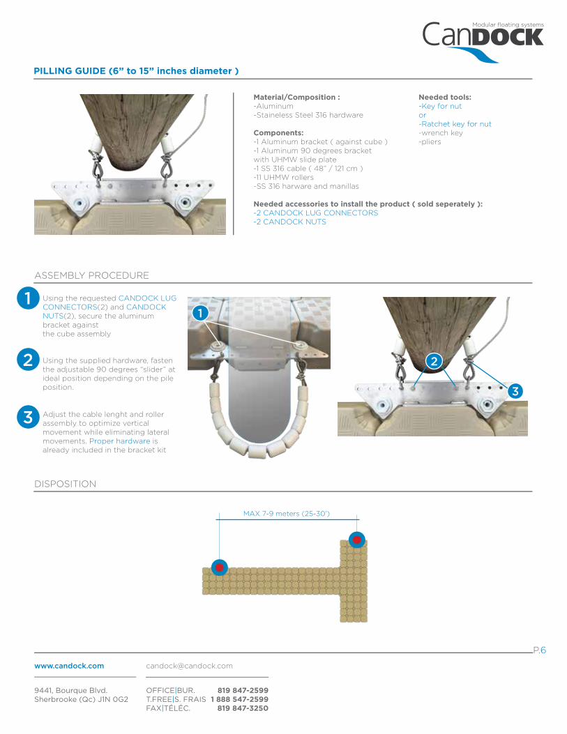
Material/Composition :-Aluminum-Staineless Steel 316 hardware
Components:-1 Aluminum bracket ( against cube )-1 Aluminum 90 degrees bracketwith UHMW slide plate-1 SS 316 cable ( 48” / 121 cm )-11 UHMW rollers-SS 316 harware and manillas
Needed accessories to install the product ( sold seperately ):-2 CANDOCK LUG CONNECTORS-2 CANDOCK NUTS
PILLING GUIDE (6” to 15” inches diameter )
ASSEMBLY PROCEDURE
Needed tools:-Key for nutor-Ratchet key for nut-wrench key-pliers
Using the requested CANDOCK LUG CONNECTORS(2) and CANDOCK NUTS(2), secure the aluminum bracket against the cube assembly
Using the supplied hardware, fasten the adjustable 90 degrees “slider” at ideal position depending on the pile position. 3
3 Adjust the cable lenght and roller assembly to optimize vertical movement while eliminating lateral movements. Proper hardware is already included in the bracket kit
11
2 2
MAX 7-9 meters (25-30’)
DISPOSITION

Modular floating systems
www.candock.com [email protected]
9441, Bourque Blvd.Sherbrooke (Qc) J1N 0G2
OFFICE|BUR. T.FREE|S. FRAIS FAX|TÉLÉC.
819 847-25991 888 547-2599
819 847-3250
P.7
ANCHOR PLATE FOR CHAIN
ASSEMBLY PROCEDURE
Material/Composition :Staineless steel 304
Dimensions :5/16 “ chain gageOR3/8” chain gage
Needed accessories(sold separately) :1 CANDOCK LUG CONNECTOR1 CANDOCK NUT
1-Simply insert the CANDOCK LUG CONNECTORS into the cube tabs wherever the ANCHORING PLATES are needed. Secure by screwing the proper CANDOCK NUTS with proper toolings. (KEY FOR NUT or RATCHET KEY FOR NUT)
*If in doubt refer your self to the CANDOCK LUG CONNECTOR section of the “regular products OWNER’S MANUAL”.
2-Insert the Staineless steel “anchor plate” into the CANDOCK LUG CONNECTOR, and to firmly secure it with the provided hardware. Make sure to angle it in the desired direction prior to final tightening.
SEE CONFIGURATION GUIDELINES FOR DETAILS
CHAIN ADJUSTER
ASSEMBLY PROCEDURE
Material/Composition :Staineless steel 304
Dimensions :Designed for 5/16 “ chain gage
Included components:1 CANDOCK LUG CONNECTOR1 CANDOCK NUT1 manilla
1-Simply insert the CANDOCK LUG CONNECTORS into the cube tabs wherever the CHAIN ADJUSTERS are needed. Make sure to insert the 90 degrees angled staineless steel part prior inserting the CANDOCK LUG CONNECTOR. Secure by screwing the proper CANDOCK NUTS with proper toolings. (KEY FOR NUT or RATCHET KEY FOR NUT)
*If in doubt refer yourself to the CANDOCK LUG CONNECTOR section of the “regular products OWNER’S MANUAL”.
**Make sure to secure your assembly by fastening the exeeding chain back to anchor line with a regular manilla.
SEE CONFIGURATION GUIDELINES FOR DETAILS
Needed tools :15/16” key wrenchKey for nutorRatchet key for nut + ratchet tool
MAX 7-9 meters (25-30’)
DISPOSITION
Needed tools :Pliers to manipulate the manillaKey for nutorRatchet key for nut + ratchet tool
MAX 7-9 meters (25-30’)
DISPOSITION

Modular floating systems
www.candock.com [email protected]
9441, Bourque Blvd.Sherbrooke (Qc) J1N 0G2
OFFICE|BUR. T.FREE|S. FRAIS FAX|TÉLÉC.
819 847-25991 888 547-2599
819 847-3250
P.8
EXTERIOR ANCHORING RING FOR CHAIN ( REGULAR OR H.D. )
ASSEMBLY PROCEDURE
Material/Composition :Staineless steel 304 (REGULAR)Staineless steel 316 (H.D.)
Dimensions :Interior diameter of the loop;2 5/8” (67mm)
Needed accessories(sold separately) :1 CANDOCK LUG CONNECTOR1 CANDOCK NUT
SEE CONFIGURATION GUIDELINES FOR DETAILS
G2 CONNECTING PIN FOR ANCHORING
ASSEMBLY PROCEDURE
Material/Composition :Staineless steel 304HDPEConcrete
Dimensions :Designed for 5/16 “ chain gage
Needed accessories(sold separately) :1 Manilla
1-Simply follow the regular G2 CONNECTING PIN assembly procedure. Make sure to validate their positionning prior to placing them. Connect chain to anchoring pin from underneath the dock ( in the water ).
1-Simply insert the CANDOCK LUG CONNECTORS into the cube tabs wherever the ANCHORING RINGS are needed. Secure by screwing the proper CANDOCK NUTS with proper toolings. (KEY FOR NUT or RATCHET KEY FOR NUT)
*If in doubt refer your self to the CANDOCK LUG CONNECTOR section of the “regular products OWNER’S MANUAL”.
2-Insert the Staineless steel “TREADED ROD” into the CANDOCK LUG CONNECTOR and firmly secure with the provided hardware.Make sure to determine ideal vertical position prior to final tightening.
IDEAL APPLICATIONS
These G2 CONNECTING PNS FOR ANCHORING are made to simply give a more aesthetic anchoring method. Also restricting its access, this method discourages any malicious person from stealing your <floating system.
SEE CONFIGURATION GUIDELINES FOR DETAILS
Needed tools :15/16” key wrenchKey for nutorRatchet key for nut + ratchet tool
MAX 7-9 meters (25-30’)
DISPOSITION
Needed tools :G2 key for pin “combo-pack”Pliers
MAX 7-9 meters (25-30’)
DISPOSITION
Modular floating systems
www.candock.com [email protected]
9441, Bourque Blvd.Sherbrooke (Qc) J1N 0G2
OFFICE|BUR. T.FREE|S. FRAIS FAX|TÉLÉC.
819 847-25991 888 547-2599
819 847-3250
P.9
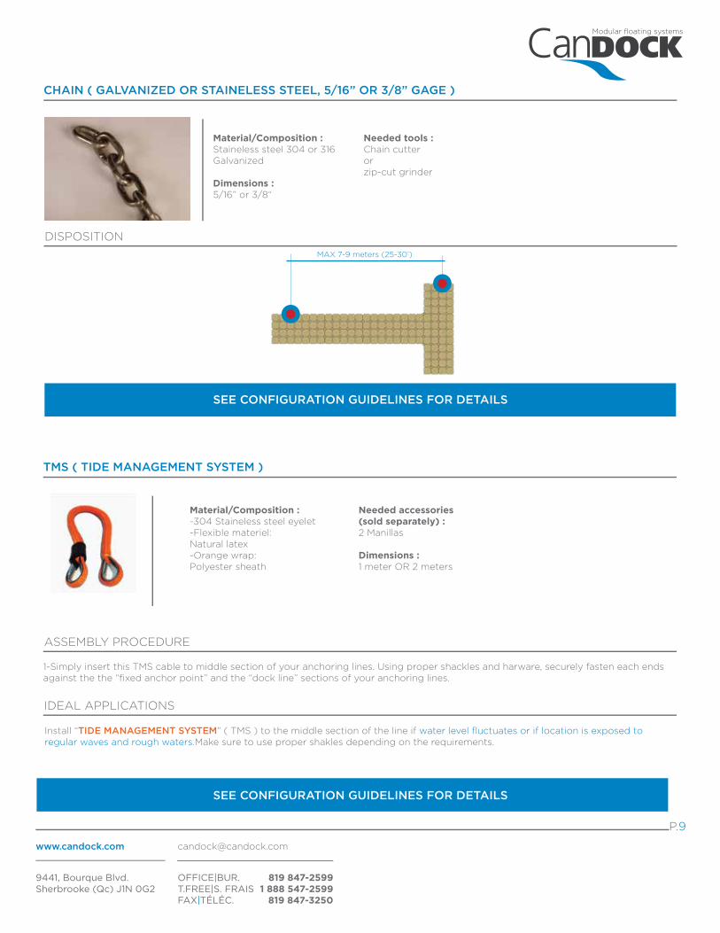
CHAIN ( GALVANIZED OR STAINELESS STEEL, 5/16” OR 3/8” GAGE )
Material/Composition :Staineless steel 304 or 316Galvanized
Dimensions :5/16” or 3/8“
SEE CONFIGURATION GUIDELINES FOR DETAILS
TMS ( TIDE MANAGEMENT SYSTEM )
ASSEMBLY PROCEDURE
Material/Composition :-304 Staineless steel eyelet -Flexible materiel:Natural latex-Orange wrap:Polyester sheath
SEE CONFIGURATION GUIDELINES FOR DETAILS
Needed accessories(sold separately) :2 Manillas
Dimensions :1 meter OR 2 meters
1-Simply insert this TMS cable to middle section of your anchoring lines. Using proper shackles and harware, securely fasten each ends against the the “fixed anchor point” and the “dock line” sections of your anchoring lines.
IDEAL APPLICATIONS
Install “TIDE MANAGEMENT SYSTEM” ( TMS ) to the middle section of the line if water level fluctuates or if location is exposed to regular waves and rough waters.Make sure to use proper shakles depending on the requirements.
Needed tools :Chain cutteror zip-cut grinder
MAX 7-9 meters (25-30’)
DISPOSITION

SUFFICIENT SPACE BETWEEN LINES
4
1
UP / DOWN UP / DOWN
-Leave sufficient spacing between crossing lines to prevent friction and premature wear.
Modular floating systems
www.candock.com [email protected]
9441, Bourque Blvd.Sherbrooke (Qc) J1N 0G2
OFFICE|BUR. T.FREE|S. FRAIS FAX|TÉLÉC.
819 847-25991 888 547-2599
819 847-3250
P.10
TIDE MANAGEMENT SYSTEM
-Install “TIDE MANAGEMENT SYSTEM”( TMS ) on the middle section of the line if water level is fluctuating ( tidal or seasonnal )or if location is exposed to regular waves and rough waters.Make sure to use proper shakles depending on the requirements.NOTE THAT THE CABLES CAN BECOMBINED TO CREATE A STURDIERANCHORING, DEPENDING ON THECHARGES THAT WILL BE APPLIEDTO THE DOCK.
4
45 DEGREE RULE
[TOP VIEW]
450
-When applyingtension on anchoringlines, always pullaway from the systemwith a 45 degreesangle. Such methodwill ensure an eventension in the linesand will optimizethe stability of theanchoring pattern
2
PARITY IN APPLIED FORCES
-Always keep parity between opposing lines and achors. Alsoequally adjust tensions in lines
2
3
When using “TIDE MANAGEMENT SYSTEMS” (TMS), make sure to complete the procedure at low tide for an optimum efficiency. ALWAYS INSTALL CABLES “UNDER TENSION”
Prior to every installation, make sure to analyse these few key points to ensure a proper installation:
-RULES AND REGULATIONS APPLYING TO YOUR AREA-MOST COMMON AND USUAL WEATHER CONDITIONS-USUAL LOADS THAT WILL BE APPLIED TO THE DOCK
-NATURE OF SEA BED-TIDAL VARIATIONS-WATER CURRENTS
CONFIGURATION GUIDELINES

For the upper section of the line,either chain or proper rope are
suggested to facilitate adjustementsthrough out the season. Proper
shakles and hardwares are mandatory
UPPER SECTION
AInstall “TIDE MANAGEMENT SYSTEM” ( TMS ) on the middle section of the lineif water level is fluctuating or if locationis exposed to regular waves and roughwaters.Make sure to use proper shakles depending on the requirements.
MIDDLE SECTION
B
Always use chainfor the first sectionof the line to preventpremature wearagainst debrislaying on sea bottom
BOTTOM SECTION
C
A
B
C
If sea bottom is “rocky” and “slipery”,A series of dead weight combined together with chain may be suitable to prevent anchor movements
ANCHOR TYPES
1-Concrete blocks2-Chemical anchors3-Helicoidal hook4-Earth Anchors
X
Y
6
2 FOR 1 RULE
1-Abide to the 2 for 1 rule to maximise the stability of your anchoring. Complete the procedure at low tide for an optimal efficiency.
6
X=2Y
i.e -If the depth of thewater plan is 2 meters,you have to move thefixed anchor aside fromthe fixing point of aminimum of 4 meters.
4 meters
2 meters
Use proper anchors depending on the nature of the seabed and loads applied to the dock.
PROPER LINE CONFIGURATIONS
If using rope as line upper section material, make sureto use proper rope and attach it as following
to ensure a strong and adjustable layout.Simply insert shackle pin trough the ropestrands.Make sure to insert in the very middle of the rope
to maximise strenght.Finally, simply attach theshackle to the anchor point on the dock
*If using a TMS, another shackle should be used on the rope at a much lower point so when you put the TMS
under tension, the shackle used to definitively secure the rope to the dock can be easily inserted.
If rope is used between lower sectionand upper section ( TMS ),
make sure to link both sections to therope with proper splicing methods
including stainless steel sleeve in loopto prevent premature wear of the rope.
5
PROPER ANCHOR CHOICE AND POSITIONNING
Modular floating systems
www.candock.com [email protected]
9441, Bourque Blvd.Sherbrooke (Qc) J1N 0G2
OFFICE|BUR. T.FREE|S. FRAIS FAX|TÉLÉC.
819 847-25991 888 547-2599
819 847-3250
P.11
5

UNDER 1 METER VARIATION
UP TO 5 METERS VARIATION
Modular floating systems
www.candock.com [email protected]
9441, Bourque Blvd.Sherbrooke (Qc) J1N 0G2
OFFICE|BUR. T.FREE|S. FRAIS FAX|TÉLÉC.
819 847-25991 888 547-2599
819 847-3250
P.11
ANCHORING STRUTS ( ALUMINUM OR STAINELESS STEEL )
ASSEMBLY PROCEDURE
Material/Composition :AluminumORStaineless steel 316
Dimensions :lenth of 10’ or 16’Custom lengths alsoavailable upon request
Needed tools :Key wrench kitHammer drill orRegular drillBits and hardware**Depending on the environement andutility of the arms.
Needed accessories(sold separately) :1 CANDOCK LUG CONNECTOR1 CANDOCK NUT
1-”CUBE” END OF THE ARMS:
1-Simply insert the LUG CONNECTORS into the cube tabs wherever the ANCHORING ARMS are needed. Secure by screwing the proper CANDOCK NUTS with proper toolings. (KEY FOR NUT or RATCHET KEY FOR NUT)
*If in doubt refer your self to the CANDOCK LUG CONNECTOR section of the “regular products OWNER’S MANUAL”.
2-Install the destined part of the arms on the CANDOCK LUG CONNECTORS and firmly secure it with the provided hardware. Make sure to angle it in the desired direction prior to final tightening.
2-”SHORE” END OF THE ARMS *** If installed on a concrete wall/structure, see last page of this manual for specific hardware suggestion***
1-Using proper hardware and tools, secure the fastening plate against concrete structure. Other structures may act as anchor points but an extensive analysis of the structure must be done to insure a strong and durable anchor point for the arm.
”CUBE” END OF THE STRUTS:
”SHORE” END OF THE STRUTS:
The anchoring struts are very useful in different situations; making it possible to solidly anchor a dock to shore line foundations or rocks,these arms have practicaly no limitations. CANDOCK offers a wide range of these arms depending on the size of the project and theconditions it is operating in. From 1 meter long to 10 meter long, for tidal variations up to 5 meters, these anchoring systems are a greatway to securelly attach your dock to permanent structures. Swivelling head, or fixed head, aluminium or staineless steel body, everything is possible. Depending on the situation, struts should be installed every 6 to 9 meters ( 20’ to 30’ ).
IDEAL APPLICATIONS
-Make sure you install the arms at low tide and verify that they will accept variations. Make sure the installation moves freely in all conditions.-If installed perpendicular to shore, use steel cables or chains positionned in a “X” conguration to prevent unwanted lateral movements.-If used in a 45 degree angle, water level variations will be limited and a minimum of 3 struts should be used in oposite directions toprevent lateral movements
NOTES
SEE IMAGES LOWER
When used perpendicularly:
When used with a certain angle:

ANCHORING STRUTS
STRUTS COMPOSITION
-Aluminum 6061 T6or
-Staineless steel 316L
STIFFENING CABLES
Modular floating systems
www.candock.com [email protected]
9441, Bourque Blvd.Sherbrooke (Qc) J1N 0G2
OFFICE|BUR. T.FREE|S. FRAIS FAX|TÉLÉC.
819 847-25991 888 547-2599
819 847-3250
P.12
ALLOWING VERTICAL VARIATIONS ( TIDAL, SEASONNAL OR FLASH FLOOD SURGES )
PREVENTING ANY LATERAL MOVEMENTS
[UP TO 5 METERS]
UP / DOWN
allowing important tidal variations and offering unmatched resistance and sturdiness.

Modular floating systems
www.candock.com [email protected]
9441, Bourque Blvd.Sherbrooke (Qc) J1N 0G2
OFFICE|BUR. T.FREE|S. FRAIS FAX|TÉLÉC.
819 847-25991 888 547-2599
819 847-3250
P.13
DOCK LEG SUPPORT
ASSEMBLY PROCEDURE
Material/Composition :Aluminum
Dimensions :Diameter of piles : 1 11/16”
The DOCK LEG SUPPORT, combined with piles 1 11/16", is a simple and affordable way to support our gangways and / or fixed dock sections. Indeed, they can be adjusted in height and are easy to manipulate. It can also be used to connect our floating systems to aa existing, floating OR fixed, structure. When installing the bracket on a floating structure, the 1 11/16 " galvanized steel pile is to be inserted into the DOCK LEG SUPPORT ,then into the cubes tabs and, finally, it must lengthened up to about 1 meter (3 feet) below the water line.If the support is to be installed on a fixed structure, the pile will necessarily have to sunked into the seabed to ensure durability. You can create an effective, affordable and easy to install attachment point to connect our systems to all other structures, floating OR fixed.
WALL ANCHORAGES ( PAINTED STEEL OR STAINLESS STEEL )
ASSEMBLY PROCEDURE
Included accessories:1 CANDOCK LUG CONNECTOR1 CANDOCK NUT
Other needed accessories and tools:Proper hardware and tools to fix thebracket to existing floating structure.
1-FIXING THE BRACKET TO THE CUBE:
1-Simply insert the CANDOCK LUG CONNECTORS into the cube tabs wherever the WALL ANCHORAGE are needed. Secure by screwing the proper CANDOCK NUTS with proper toolings. (KEY FOR NUT or RATCHET KEY FOR NUT) *If in doubt refer your self to the CANDOCK LUG CONNECTOR section of the -“regular products OWNER’S MANUAL”.
2-Install the destined part of the bracket on the CANDOCK LUG CONNECTORS prior to firmly secure it with the provided hardware. Make sure to angle it in the desired direction prior to final tightening.
2-FIXING THE BRACKET TO THE FLOATING STRUCTURE:
1-Using proper hardware and tools , secure the fastening plate against the floating structure*. Other structure may act as anchor points but an extensive analysis of the structure must be done. (*additionnal parts andbrackets may be needed to properly connect to the dock if heights don’t concur)
Needed accessories(sold separately) :Pile 1 11/16”
Material/Composition :Painted steel or Satineless steel
Needed tools :15/16” key wrenchKey for nutorRatchet key for nut + ratchet tool
MUST BE INSTALLED ON A FLOATING STRUCTURE OR AGAINST A FIXED STRUCTURE IN AN ENVIRONMENT WHERE WATER DOES NOT FLUCTUATE.
Needed tools :Piling driver 1 11/16”Zip cut grinder ( to cut-off exceeding pipe )Key wrenchDrill and bits