analytical Method for Designing Anchor Bolts of Structures ... · PDF fileSchool of Mechanical...
11
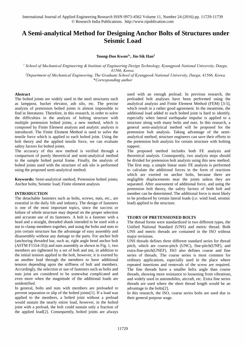
International Journal of Applied Engineering Research ISSN 0973-4562 Volume 11, Number 24 (2016) pp. 11729-11739 © Research India Publications. http://www.ripublication.com 11729 A Semi-analytical Method for Designing Anchor Bolts of Structures under Seismic Load Young-Doo Kwon 1 ∗ , Jin-Sik Han 2 1 School of Mechanical Engineering & Institute of Engineering Design Technology, Kyungpook National University, Daegu, 41566, Korea. 2 Department of Mechanical Engineering, The Graduate School of Kyungpook National University, Daegu, 41566, Korea. *Corresponding author Abstract The bolted joints are widely used in the steel structures such as lamppost, bucket elevator, ash silo, etc. The precise analysis of pretension bolted joints is almost impossible to find in literatures. Therefore, in this research, in order to solve the difficulties in the analysis of bolting structure with multiple pretension bolted joints, a new method, which is composed by Finite Element analysis and analytic analysis is introduced. The Finite Element Method is used to solve the tensile force which is applied to each bolted joint. Using the bolt theory and the applied tensile force, we can evaluate safety factors for bolted joints. The accuracy of this new method is verified through a comparison of purely theoretical and semi-analytical method to the sample bolted portal frame. Finally, the analysis of bolted joints used with the structure of ash silo is performed using the proposed semi-analytical method. Keywords: Semi-analytical method; Pretension bolted joints; Anchor bolts; Seismic load; Finite element analysis INTRODUCTION The detachable fasteners such as bolts, screws, nuts, etc., are essential in the daily life and industry. The design of fasteners is one of the most important topics, since the success or failure of whole structure may depend on the proper selection and accurate use of its fasteners. A bolt is a fastener with a head and a straight, threaded shank intended to be used with a nut to clamp members together, and using the bolts and nuts to join certain structure has the advantage of easy assembly and disassembly without any damage to the parts. For anchor bolt (anchoring threaded bar, such as, right angle bend anchor bolt (ASTM F1554-35)) and nuts assembly as shown in Fig. 1, two members are tightened by a set of bolt and nut, in addition to the initial tension applied to the bolt, however, it is exerted by an another load through the members to have additional tension depending upon the stiffness of bolt and members. Accordingly, the selection or use of fasteners such as bolts and nuts joint are considered to be somewhat complicated and even more when the magnitude of the additional loads are unidentified. In general, bolts and nuts with members are preloaded to prevent separation or slip of the bolted joints[1]. If a load was applied to the members, a bolted joint without a preload would sustain the nearly entire load, however, in the bolted joint with a preload, the bolt could sustain only a fraction of the applied load[2]. Consequently, bolted joints are always used with an enough preload. In previous research, the preloaded bolt analyses have been performed using the analytical analysis and Finite Element Method (FEM) [3-5], which result in a rather good agreement. In the meantime, the additional load added to each bolted joint is hard to identify, especially when lateral earthquake impulse is applied to a structure along with many bolts and nuts. In this research, a general semi-analytical method will be proposed for the pretension bolt analysis. Taking advantage of the semi- analytical method, structure engineers can save their efforts to the pretension bolt analysis for certain structure with bolting support. The proposed method includes both FE analysis and theoretical analysis. Consequently, two analysis steps should be divided for pretension bolt analysis using this new method. The first step, a simple linear static FE analysis is performed to calculate the additional forces in the form of reactions which are exerted on anchor bolts, because there are negligible displacements near the joints unless they are separated. After assessment of additional force, and using the pretension bolt theory, the safety factors of both bolt and member can be determined. The additional force is most likely to be produced by certain lateral loads (i.e. wind load, seismic load) applied to the structure. TEORY OF PRETENSIONED BOLTS The thread forms were standardized in two different types, the Unified National Standard (UNS) and metric thread. Both UNS and metric threads are contained in the ISO without major revisions. UNS threads defines three different standard series for thread pitch, which are coarse-pitch (UNC), fine-pitch(UNF), and extra-fine-pitch(UNEF). ISO also defines coarse and fine series of threads. The coarse series is most common for ordinary applications, especially used in the place where repeated insertions and removals of the screw are required. The fine threads have a smaller helix angle than coarse threads, showing more resistance to loosening from vibrations, and widely used in automobiles, aircraft, etc. Extra fine series threads are used where the short thread length would be an advantage to the bolts[2]. In this research, the ISO, coarse series bolts are used due to their general purpose wage.
Transcript of analytical Method for Designing Anchor Bolts of Structures ... · PDF fileSchool of Mechanical...
International Journal of Applied Engineering Research ISSN 0973-4562 Volume 11, Number 24 (2016) pp. 11729-11739
© Research India Publications. http://www.ripublication.com
11729
A Semi-analytical Method for Designing Anchor Bolts of Structures under
Seismic Load
Young-Doo Kwon1∗, Jin-Sik Han2
1 School of Mechanical Engineering & Institute of Engineering Design Technology, Kyungpook National University, Daegu,
41566, Korea. 2Department of Mechanical Engineering, The Graduate School of Kyungpook National University, Daegu, 41566, Korea.
*Corresponding author
Abstract
The bolted joints are widely used in the steel structures such
as lamppost, bucket elevator, ash silo, etc. The precise
analysis of pretension bolted joints is almost impossible to
find in literatures. Therefore, in this research, in order to solve
the difficulties in the analysis of bolting structure with
multiple pretension bolted joints, a new method, which is
composed by Finite Element analysis and analytic analysis is
introduced. The Finite Element Method is used to solve the
tensile force which is applied to each bolted joint. Using the
bolt theory and the applied tensile force, we can evaluate
safety factors for bolted joints.
The accuracy of this new method is verified through a
comparison of purely theoretical and semi-analytical method
to the sample bolted portal frame. Finally, the analysis of
bolted joints used with the structure of ash silo is performed
using the proposed semi-analytical method.
Keywords: Semi-analytical method; Pretension bolted joints;
Anchor bolts; Seismic load; Finite element analysis
INTRODUCTION
The detachable fasteners such as bolts, screws, nuts, etc., are
essential in the daily life and industry. The design of fasteners
is one of the most important topics, since the success or
failure of whole structure may depend on the proper selection
and accurate use of its fasteners. A bolt is a fastener with a
head and a straight, threaded shank intended to be used with a
nut to clamp members together, and using the bolts and nuts to
join certain structure has the advantage of easy assembly and
disassembly without any damage to the parts. For anchor bolt
(anchoring threaded bar, such as, right angle bend anchor bolt
(ASTM F1554-35)) and nuts assembly as shown in Fig. 1, two
members are tightened by a set of bolt and nut, in addition to
the initial tension applied to the bolt, however, it is exerted by
an another load through the members to have additional
tension depending upon the stiffness of bolt and members.
Accordingly, the selection or use of fasteners such as bolts and
nuts joint are considered to be somewhat complicated and
even more when the magnitude of the additional loads are
unidentified.
In general, bolts and nuts with members are preloaded to
prevent separation or slip of the bolted joints[1]. If a load was
applied to the members, a bolted joint without a preload
would sustain the nearly entire load, however, in the bolted
joint with a preload, the bolt could sustain only a fraction of
the applied load[2]. Consequently, bolted joints are always
used with an enough preload. In previous research, the
preloaded bolt analyses have been performed using the
analytical analysis and Finite Element Method (FEM) [3-5],
which result in a rather good agreement. In the meantime, the
additional load added to each bolted joint is hard to identify,
especially when lateral earthquake impulse is applied to a
structure along with many bolts and nuts. In this research, a
general semi-analytical method will be proposed for the
pretension bolt analysis. Taking advantage of the semi-
analytical method, structure engineers can save their efforts to
the pretension bolt analysis for certain structure with bolting
support.
The proposed method includes both FE analysis and
theoretical analysis. Consequently, two analysis steps should
be divided for pretension bolt analysis using this new method.
The first step, a simple linear static FE analysis is performed
to calculate the additional forces in the form of reactions
which are exerted on anchor bolts, because there are
negligible displacements near the joints unless they are
separated. After assessment of additional force, and using the
pretension bolt theory, the safety factors of both bolt and
member can be determined. The additional force is most likely
to be produced by certain lateral loads (i.e. wind load, seismic
load) applied to the structure.
TEORY OF PRETENSIONED BOLTS
The thread forms were standardized in two different types, the
Unified National Standard (UNS) and metric thread. Both
UNS and metric threads are contained in the ISO without
major revisions.
UNS threads defines three different standard series for thread
pitch, which are coarse-pitch (UNC), fine-pitch(UNF), and
extra-fine-pitch(UNEF). ISO also defines coarse and fine
series of threads. The coarse series is most common for
ordinary applications, especially used in the place where
repeated insertions and removals of the screw are required.
The fine threads have a smaller helix angle than coarse
threads, showing more resistance to loosening from vibrations,
and widely used in automobiles, aircraft, etc. Extra fine series
threads are used where the short thread length would be an
advantage to the bolts[2].
In this research, the ISO, coarse series bolts are used due to
their general purpose wage.

International Journal of Applied Engineering Research ISSN 0973-4562 Volume 11, Number 24 (2016) pp. 11729-11739
© Research India Publications. http://www.ripublication.com
11730
Figure 1. Effective diameter for member
1. Tensile Stress Area A thread rod of a bolt is mostly subjected to a pure tensile load
along the axis of screw, and the strength of the rod has an
approximate but not exact relation with the area of its minor
diameter, minD . However, tension testing of threaded rods
shows that the tensile strength is better defined using both of
the minor and pitch diameters with certain relationships shows
in below.
Referring to ISO threads, the tensile-stress area, tA is defined
by:
2
min
4 2
pt
D DA
(1)
0.649519p majD D P
(2)
min 1.226869majD D P
(3)
The stress in a threaded rod due to a pure axial tensile load F
is then
tt
FA
(4)
Applying Eqs. (1-4), the principal dimensions of ISO metric
standard screw threads are calculated and tabulated in Table 1.
Table 1 Size and load information of portal frame
Name Value
Width(W) 1 m
Height(H) 2 m
Force(F) 100 N
/ 2W 30 N
Young’s modulus 207 GPa
Poisson’s ratio 0.3
2. Determination of Apex Angle using FEM The stress distribution at the bolted members has a complex
geometry [6]. Therefore, an accurate calculation for the
stressed volume of the members is quite complicated. In order
to calculate the stressed volume, Several approaches[7-9]
have been proposed. Ito[9] determined the pressure
distribution at the member interface using the ultrasonic
techniques. The result shows that the pressure stays high to a
distance of 1.5 radii, then the pressure fall off farther away
from the bolt. Thus Ito suggests that using Rotscher’s
pressure-cone method for stiffness calculation with a variable
cone angle is appropriate. Furthermore, for the convenience of
computing, we choose to use a simpler approach using a fixed
angle. Two frustums which have been shown in Figure 1 are
used to present the stress distribution. As a result, once the
cone half-apex angle was determined, the effective diameter
of the cross-section area would be found, and the effective
cross-section area of members can be estimated. Consequently,
the cone half-apex angle is a key parameter to the
determination of the stiffness of the members. However, the
value of apex angle was quite differently defined by several
researchers due to the material or size of the washer used.
While Rotscher’s used 45 , Joseph E. Shigley[10]
assumes the apex angle as 30, and Robert L. Norton
[2]approximately use apex angle as 42. The apex angle
can be determined as 34.65 degree according to the stiffness
in Fig. 2, which has been obtained by FEM[11]. The apex
angle of 34.65 can be used further for theoretical calculation
in respect to the stiffness of members in this research.
Figure 2. Stiffness chart regarding apex angle
3. Effective Cross-sectional Area of Compression Members The cross-sectional area of compression in member mA can
be calculated by
2 2( )4
m effA d d
(5)

International Journal of Applied Engineering Research ISSN 0973-4562 Volume 11, Number 24 (2016) pp. 11729-11739
© Research India Publications. http://www.ripublication.com
11731
as shown in Fig. 1, the effective diameter effd , can be simply
calculated through
2 3
2eff
d dd
(6)
2 1.5d d
(7)
3 2 tand d l
(8)
where 2d is the small-end diameter of the frustum-cone, 3d
is the big-end diameter. is the determined cone apex angle.
4. Determination of Preload for Bolted joints The pretension bolts are widely used in the bolted structures.
It is practical to preload the joints by tightening the bolts with
appropriate torque to create tensile loads along its screw axis.
Here, a preload which generates bolt stress as % of the
proof strength is used. The preload can be calculated by
i P tF S A (9)
where PS is the minimum proof stress, tA is the tensile
stress area, is the factor of preload with the value, say 50%.
The use of a pretension bolted joints provide an advantage
that the bolts can sustain a constant force even the applied
load of structure varying with time.
5. Applied Load to Pretension Bolted Joints
Figure 3. Preloaded bolt diagram
Fig. 3 shows the load-deflection behavior of both bolt and
member on common axes. As the slope of member line is
higher than that of bolt line, we can know the truth that the
bolt has a relative small stiffness. Generally, a bolt has 1/5 to
1/3 of the stiffness of the member.
For an external load NP applied to the member of a bolted
joint, the applied force would cause a reduction to the
compression force ( mP ) of the member and an addition to the
tension force ( bP ) of the bolt. Since the bolt and member
have different stiffness (member with a lager stiffness) but
identical length change, then the applied member force mP is
larger than the applied bolt force bP . This truth is important
to the design of bolted joint. As a result, a low stiffness bolt
with a high stiffness member would be preferable, so that the
bolt can only sustain a small proportion of the applied force.
Figure 4. Preloaded bolt failure diagram
If the applied load is allowed to increase, the compression
force acting on the member will continue to decrease as long
as the member fully unloaded, referring to Fig. 4, any further
increase in the applied load will result a gap between the bolt
and member, then cause the bolted joint to fail.
As shown in Fig. 3 the applied load to bolted joints can be
expressed as
N w m bP P F P P
(10)
where P is the external load applied to a structure, wF is the
force generated by the dead load of the structure.
Consequently, the load within member mF is
m i mF F P
(11)
The load within bolt bF is
b i bF F P
(12)
In the section 2.5, the stiffness of bolt and member are defined
respectively. Subsequently, the joint constant C is defined as

International Journal of Applied Engineering Research ISSN 0973-4562 Volume 11, Number 24 (2016) pp. 11729-11739
© Research India Publications. http://www.ripublication.com
11732
b
b m
kCk k
(13)
Utilizing identical change of length due to the external applied
load then
b m
b m
P Pk k
(14)
Accordingly, the increased tension force of bolt, bP can be
expressed as
b NP CP
(15)
and the reduction of compression force, mP is
(1 )m NP C P
(16)
Consequently, the applied load within member and bolt due to
the external load applied to member will become
(1 )m i NF F C P (17)
b i NF F CP (18)
For an external load which can be used to separate the
member from bolt, the critical load CP is defined as shown in
Eq. (17) by setting mF to zero.
1
iC
FPC
(19)
As a result, the safety factor of both bolt and member can be
determined as
proofB
i N
FFS
F CP
(20)
(1 )
C iM
N N
P FFSP P C
(21)
where FSB is the safety factor of bolt, FSM is the safety factor
of member, proofF is the proof load of the bolt.
Before the external load such as earth quake load is applied,
the factors of safety can be expressed as
proofB
i w
FFS
F CF
(22)
(1 )
iM
w
FFSF C
(23)
DESIGN PROCESS OF ANCHOR BOLTS
1. Theoretical Analysis for Bolted Joint used with Simple Portal Frame For the analysis of bolted joint, the external applied load P is
considered as the critical term. In practical design of a bolted
joint, the external applied load is hardly to be calculated for
the situation of a structure with complex shape. Consequently,
a Finite Element Method (FEM) analysis is utilized to
calculate the external applied load for the bolted joint.
This section, in order to verify the new method for the
analysis of bolted joint, a simple bolted portal frame is
employed to analysis through the method of both beam theory
and FE (Finite Element).
Figure 5. Schematic diagram of portal frame
As shown in Fig. 5 a portal frame structure is established and
bolted on ground. The external load and dead load (gravity)
are applied to the frame. For theoretical analysis, we would
like first to evaluate the applied force to bolted joint at each
bottom of the bolted portal frame.
In order to evaluate the analysis of a bolted joint, the safety
factors of bolt and member are used as measurement. For the
safety factors of bolt and member are both larger than 1 unity,
we conclude that the bolted joint is safe otherwise the bolted
joint is failed. As mentioned previously, the reaction forces
AvR , BvR at the bottom of portal frame are required to

International Journal of Applied Engineering Research ISSN 0973-4562 Volume 11, Number 24 (2016) pp. 11729-11739
© Research India Publications. http://www.ripublication.com
11733
evaluate the safety factor of bolt and member. The Euler-
Bernoulli beam theory [12] was used in the analysis of portal
frame for the small deflection of frames.
Figure 6. Free body diagram of portal frame
According to Fig. 6 the reaction moment and horizontal
reaction force are independent of the gravity of portal frame,
the vertical term / 2W can be excluded for calculation
simplicity. Nevertheless, the gravity effect should be included
at the last step of the calculation to the vertical reaction force.
Accordingly, there are six unknown reactions, (i.e. two
horizontal reaction forces AhR , BhR , two vertical reaction
forces AvR , BvR , and two reaction moments AM , BM ),
but only three equilibrium equations can be established. For
such a problem that the number of equilibrium equations is
less than the number of unknowns, we can name this problem
as statically indeterminate. For an indeterminate problem,
some additional considerations should be included for
calculation.
Figure 7. Deformation schematic of portal frame
In accordance with Fig. 7 three extra equilibrium equations
are assumed (i.e. the identical deflections a , b , and the
identical slope at two corners). Furthermore, with the
horizontal force, vertical force, moment equilibrium equations,
the six unknowns can be solved successively.
In order to solve equations through a numerical method, the
six equations of equilibrium (at A and B) above can be
rearranged in a matrix form, which as
2
2
3 2 3 2
0 0 1 0 1
0 1 0 0 1 0
1 0 0 1 0 00
0 02 3 3 6 6 0
00 06 6 3 2 3
0
0 06 2 6 2
Ah
Av
A
Bh
Bv
B
W
R FHR
H W H W W H W M FHR
W H W W H H W RHM
H H H H
(24)
Regarding the portal frame, the size and load conditions are
specified as shown in Table 1.
With Table 1 and Eq.30, the reaction force and moment can be
simply calculated using numerical software such as
FORTRAN or MATLAB, The results calculated as
50.0000 92.3077 53.8462 50.0000 92.3077 53.8462
TAh Av A Bh Bv B
T
R R M R R M
It is notable that the effect of dead load should be included in
this step, then we can simply add the gravity G to the terms
of AvR , BvR , consequently, the results are
50.0000 62.3077 53.8462 50.0000 122.308 53.8462
TAh Av A Bh Bv B
T
R R M R R M
For the problem of portal frame as shown in Fig. 5 we can
conclude that the weight force applied to the bolted joint wF
is identical to the gravity force G . We proposed two 6 1.0M
bolts with the class number of 5.8 for the bolted portal frame.
The required data for analysis of the bolted joint are presented
in Table 2. The calculated results for the safety factor of bolt
and member are arranged in Table 3.

International Journal of Applied Engineering Research ISSN 0973-4562 Volume 11, Number 24 (2016) pp. 11729-11739
© Research India Publications. http://www.ripublication.com
11734
Table 2 Data for bolt analysis for portal frame
Name Value
Stiffness of bolt ( bK ) 80 KN/mm
Stiffness of member ( mK ) 6.355 MN/mm
Major diameter( majD ) 6 mm
Pitch ( p ) 1 mm
Bolt length ( boltl ) 80 mm
Thread length ( thdl ) 18 mm
Clamped member length ( l ) 70 mm
Unthreaded Shank length ( sl ) 62 mm
Threaded shank length ( tl ) 8 mm
Min. proof load ( pF ) 7647 N
Initial preload ( iF ) 5372 N
Joint constant ( C ) 0.03128
Weight force ( wF ) 30 N
Critical force ( cF ) 5577 N
Table 3 Results of theoretical bolt analysis for portal frame
Name Value
Max. reaction force (N) 62.31
FSM 89.50
FSB 1.423
※ FSM denotes safety factor of member
FSB denotes safety factor of bolt
For the engineering design of bolted joints, the bolted joints
have a high endurability to the compression force.
Consequently, only the tension force to the bolted joint is
considered in this research.
2. Finite Element Analysis for Bolted Portal Frame In order to determine the safety factor of bolts and members,
the evaluation for the applied force to the bolted joint is
necessary. For practical problems, if a structure had a complex
shape or load, it is difficult to calculate the corresponding
applied force theoretically. Consequently, the Finite Element
Method (FEM) is utilized to evaluate the applied force to the
bolted joint which is used with the bolted structures. Above all,
it is necessary to verify the accuracy of the bolted joint
analysis using FEM. The same portal frame model as shown
in Fig. 8 is prepared for the FE analysis. The FE analysis was
performed using the commercial software ABAQUS. The
boundary conditions are defined same as which used in theory
analysis (Table 2).
Figure 8. FEM model of portal frame
As shown in Fig. 8, the translational freedoms of nodes on the
bottom of the portal frame are fixed. The applied force to the
bolted joint can be simply evaluated through the calculation of
reaction force which occurred at each bottom of the bolted
portal frame.
Figure 9. Reaction force contour at the bottom of portal frame
Fig. 9 presents the reaction force at the bottom of portal frame,
the reaction force occurred due to the gravity and applied
external force. The reaction forces at left and right bottom are
respectively obtained as -62.4 and 122.4. As a result, we can
know that the calculated reaction force using FEM has a
negligible error with respect to that using theory. Finally, with
the pretension bolt theory and the evaluated applied force, the
safety factors of bolts and members is evaluated as below.
Referring to Table 4, the negligible error of safety factor
indicates that using semi-analytical method for the analysis of
bolted joints is reliable.
Table 4 Results of bolt analysis for portal frame using FEM
Name Value
Max. reaction force (N) 62.40
FSM 89.37
FSB 1.423
Error for FSM 0.15 %
Error for FSB 0
※ FSM denotes safety factor of member
FSB denotes safety factor of bolt

International Journal of Applied Engineering Research ISSN 0973-4562 Volume 11, Number 24 (2016) pp. 11729-11739
© Research India Publications. http://www.ripublication.com
11735
PRACTICAL MODEL FOR ANCHOR BOLT ANALYSIS
Since we have verified the accuracy of the semi-analytical
method, the method can be used further for the analysis of
bolted joints used with a practical bolted model. The only
thing we need to do is to determine the applied reaction force
at which a bolted joint should be used. In this section, we will
introduce a practical engineering bolted model for the analysis
of bolted joint.
1. FEM Model and Boundary Conditions i. FEM Model
(a) 2D model of ash silo
(b) Finite element model of ash silo
Figure 10. Model of ash silo
The model, as shown in Fig. 10 is an ash silo which is used at
the coal-fired thermal power plant. The specific size of ash
silo is 10.64m in height and 4.5m in width. Commonly, an ash
silo can be subjected to dead load and wind load, in the case
of earthquake, the ash silo also can be subjected to a seismic
load. The anchor bolts are used to fix the structure of ash silo
to ground. Consequently, if the appropriate bolts are used in
certain situation is important. The semi-analytical method for
analysis of bolted joints is proposed in the previous section.
The FEM model of ash silo is established and shown in Fig.
10 (b).
In order to obtain a fine mesh quality in spite of the complex
shape of ash silo, the commercial software HyperMesh 12.0 is
utilized to do the work of meshing. In addition to that,
HyperMesh is also employed to do the preprocess work of
FEM such as material property assignment, applying load,
analysis step definition, etc.
Regarding the FEM model of ash silo, there are 89,093 nodes
and 90,604 elements used for the analysis. The linear quad,
triangle shell elements are used for the body of ash silo. The
linear hex solid element is used at the position in which the
bolted joints are assembled. Here, in order to evaluate the
applied force to the bolted joints at the situation of the ash silo
under certain load, at the same positions of bolted joints,
instead of modeling a bolt, a simple cube is modeled as shown
in Fig. 11. Consequently, the reaction force can be simply
obtained through FE analysis.
Figure 11. Cubes schematic in the bottom of ash silo
ii. Material Properties The steel of SS400 is used for the material of ash silo, the
material properties are displayed in Table 5.
Table 5 Material properties of ash silo
Young’s
modulus
(GPa)
Poisson’s
ratio
Density
(Mg/mm3)
Yield
strength
(MPa)
SS400 207 0.26 7.8e-9 400
The total weight of ash silo (i.e. including ash) is 69.5 ton, the
net weight is 17 ton and the axial stiffness of the main column
is 208.6kN/mm. For the analysis of bolted joints used with ash
silo, several load conditions to the ash silo should be
considered. Typically, the wind load and seismic load
conditions are considered for the actual situation. Compared
with wind load, the seismic load is more harmful to the
structure of ash silo as well as the bolted joints [13]. To meet
the design requirements of the bolted joints under extreme
International Journal of Applied Engineering Research ISSN 0973-4562 Volume 11, Number 24 (2016) pp. 11729-11739
© Research India Publications. http://www.ripublication.com
11736
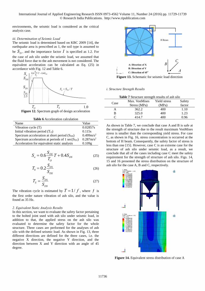
environments, the seismic load is considered as the critical
analysis case.
iii. Determination of Seismic Load The seismic load is determined based on KBC 2009 [14], the
earthquake area is prescribed as 1, the soil type is assumed to
be DS , and the importance factor I is specified as 1.2. For
the case of ash silo under the seismic load, we assumed that
the fluid force due to the ash movement is not considered. The
equivalent acceleration can be calculated as Eq. (25) in
accordance with Fig. 12 and Table 6.
Figure 12. Spectrum graph of design acceleration
Table 6 Acceleration calculation
Name Value
Vibration cycle (T) 0.02857s
Initial vibration period (TO) 0.115s
Spectrum acceleration at short period (SDS) 0.499m/s2
Spectrum acceleration at periods of 1 sec(SD1) 0.287m/s2
Acceleration for equivalent static analysis 0.109g
0.6 0.4DSa DS
O
SS T ST
(25)
10 0.2 D
DS
STS
(26)
1DS
DS
STS
(27)
The vibration cycle is estimated by 1/T f , where f is
the first order nature vibration of ash silo, and the value is
found as 35 Hz.
2. Equivalent Static Analysis Results In this section, we want to evaluate the safety factor pertaining
to the bolted joint used with ash silo under seismic load, in
addition to that, the applied stress on the ash silo was
evaluated to determine the safety factor for the whole
structure. Three cases are performed for the analyses of ash
silo with the defined seismic load. As shown in Fig. 13, three
different directions are defined for the three cases, i.e. the
negative X direction, the negative Y direction, and the
direction between X and Y direction with an angle of 45
degree.
Figure 13. Schematic for seismic load direction
i. Structure Strength Results
Table 7 Structure strength results of ash silo
Case Max. VonMises
Stress (MPa)
Yield stress
(MPa)
Safety
factor
A 362.2 400 1.10
B 325.0 400 1.23
C 414.7 400 0.96
As shown in Table 7, we conclude that case A and B is safe at
the strength of structure due to the result maximum VonMises
stress is smaller than the corresponding yield stress. For case
C, as shown in Fig. 16, stress concentration is occurred at the
bottom of H beam. Consequently, the safety factor of stress is
less than one [15]. However, case C is an extreme case for the
structure of ash silo under seismic load, as a result, we
conclude that all of the cases including case C meet the safety
requirement for the strength of structure of ash silo. Figs. 14,
15 and 16 presented the stress distribution on the structure of
ash silo for the case A, B and C, respectively.
Figure 14. Equivalent stress distribution of case A

International Journal of Applied Engineering Research ISSN 0973-4562 Volume 11, Number 24 (2016) pp. 11729-11739
© Research India Publications. http://www.ripublication.com
11737
Figure 15. Equivalent stress distribution of case B
Figure 16. Equivalent stress distribution of case C
ii. Anchor Bolt Analysis Results As previous discussed, to evaluate the safety factor of the bolt
and member, we should first get the reaction force at the
position where an actual bolt would be installed. For modeling
convenience, we modeled several cubes with the same number
of bolted joints. According to Newton’s third law, the
generation of negative reaction force at the position of bolted
joint means a tensile force applied to the bolted joint. Only the
negative reaction force is considered for the analysis of the
bolted joints for that the bolted joints with a good resistance to
the compressive force.
Figure 17. Reaction force distribution of case A
Figure 18. Reaction force distribution of case B
Figure 19. Reaction force distribution of case C
Figs. 17-19 respectively displayed the reaction force
distribution occurred at the modeled cubes at the bottom of
the bolted ash silo for the case A, B and C. For case A, the
negative reaction force generated at the upper half of the
bottom. For case B, the negative reaction force generated at
the right half of the bottom. For case C, the negative reaction
force generated at the upper right of the bottom. The force
wF can be obtained through a FE analysis to the model of ash
silo without external load.
International Journal of Applied Engineering Research ISSN 0973-4562 Volume 11, Number 24 (2016) pp. 11729-11739
© Research India Publications. http://www.ripublication.com
11738
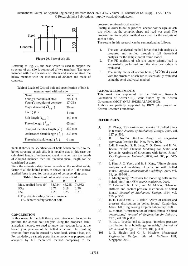
Figure 20. Base of ash silo
Referring to Fig. 20, the base which is used to support the
structure of ash silo is composed of two members. The upper
member with the thickness of 30mm and made of steel, the
below member with the thickness of 300mm and made of
concrete.
Table 8 Loads of Critical bolt and specification of bolt &
member used with ash silo
Name Value
Young’s modulus of steel 207 GPa
Young’s modulus of concrete 17 GPa
Major diameter( majD ) 20 mm
Pitch ( p ) 4 mm
Bolt length ( boltl ) 450 mm
Thread length ( thdl ) 65 mm
Clamped member length ( l ) 330 mm
Unthreaded shank length ( sl ) 330 mm
Threaded shank length ( tl ) 0 mm
Table 8 shows the specification of bolts which are used to the
bolted structure of ash silo. It is notable that in this case the
calculated length of unthreaded shank is larger than the length
of clamped member, then the threaded shank length can be
considered as zero.
Since the ultimate safety factor depends on the smallest safety
factor of all the bolted joints, as shown in Table 9, the critical
applied force is used for the analysis of corresponding case.
Table 9 Results of bolt analysis for ash silo
A B C
Max. applied force (N) 38,934 46,255 74,982
FSM 3.77 3.18 1.96
FSB 1.26 1.25 1.21
※ FSM denotes safety factor of member
FSB denotes safety factor of bolt
CONCLUSTION
In this research, the bolt theory was introduced. In order to
perform the anchor bolt analysis using the proposed semi-
analytical method, we need to know the reaction force at the
bolted joint position of the bolted structure. The resulting
reaction force may be caused by wind load, seismic load, etc.
For validation, a sample portal frame model was prepared and
analyzed by full theoretical method comparing to the
proposed semi-analytical method.
Finally, in order to do the practical anchor bolt design, an ash
silo which has the complex shape and load was used. The
proposed semi-analytical method was used for the analysis of
anchor bolts.
The results in this research can be summarized as follows:
1. The semi-analytical method for anchor bolt analysis is
proposed and verified through a full theoretical
analysis for the sample portal frame model.
2. The FE analysis of ash silo under seismic load is
successfully performed and the structural safety is
evaluated.
3. The safety factor of anchor bolts ( 20 4M ) used
with the structure of ash silo is successfully evaluated
using the semi-analytical method.
ACKNOWLEDGEMENTS
This work was supported by the National Research
Foundation of Korea(NRF) Grant funded by the Korean
Government(MOE) (NRF-2012R1A1A2008903).
Authors are partially supported by BK21 plus project of
Korean Research Foundation.
REFERENCES
[1] O. Zhang, "Discussions on behavior of Bolted joints
in tension," Journal of Mechanical Design, 2005, vol.
127, p. 506.
[2] R. L. Norton, Machine design: an integrated approach: Prentice-Hall New York, 1996.
[3] J.-H. Hwangbo, S. H. Jang, Y. D. Kwon, and H. W.
Kwon, "Finite Element Modeling for Static and
Dynamic Analysis of Structures with Bolted Joint,"
Key Engineering Materials, 2006, vol. 306, pp. 547-
552.
[4] J. Kim, J. C. Yoon, and B. S. Kang, "Finite element
analysis and modeling of structure with bolted
joints," Applied Mathematical Modelling, 2007, vol.
31, pp. 895-911.
[5] J. Montgomery, "Methods for modeling bolts in the
bolted joint," in ANSYS user’s conference, 2002.
[6] T. Lehnhoff, K. I. Ko, and M. McKay, "Member
stiffness and contact pressure distribution of bolted
joints," Journal of Mechanical Design, 1994, vol.
116, p. 550.
[7] H. H. Gould and B. B. Mikic, "Areas of contact and
pressure distribution in bolted joints," Cambridge,
Mass.: MIT Engineering Projects Laboratory,1970.
[8] N. Motosh, "Determination of joint stiffness in bolted
connections," Journal of Engineering for Industry,
1976, vol. 98, p. 858.
[9] Y. Ito, J. Toyoda, and S. Nagata, "Interface pressure
distribution in a bolt-flange assembly," Journal of Mechanical Design, 1979, vol. 101, p. 330.
[10] J. E. Shigley and C. R. Mischke, Mechanical Engineering Design., 6th ed.: McGraw Hill,
Singapore, 2001.

International Journal of Applied Engineering Research ISSN 0973-4562 Volume 11, Number 24 (2016) pp. 11729-11739
© Research India Publications. http://www.ripublication.com
11739
[11] N. S. Al-Huniti, "Computation of Member Stiffness
in Bolted Connections Using the Finite Element
Analysis#," Mechanics based design of structures and machines, 2005, vol. 33, pp. 331-342.
[12] S. P. Timošenko, History of strength of materials: with a brief account of the history of theory of elasticity and theory of structures: DoverPublications.
com, 1953.
[13] B. S. Taranath, Structural analysis and design of tall
buildings: Steel and composite construction: CRC
Press, 2011.
[14] Ministry of Land, Infrastructure and Transport,
Korean building construction standards, 2009.
[15] G. Gazetas, I. Anastasopoulos and E. Garini, "
Geotechnicaldesignwithapparentseismicsafetyfactors
well-bellow1," Soil DynamicsandEarthquakeEngineering, 2014, vol.57,
pp. 37-45.