Analysis of Vehicle Cooling Systems Approaches to · PDF fileAnalysis of Vehicle Cooling...
16
Thermotec Engineering Services GmbH Analysis of Vehicle Cooling Systems – Approaches to Handle System Complexity and a Huge Number of Variants Robert Tauscher
-
Upload
nguyenmien -
Category
Documents
-
view
213 -
download
0
Transcript of Analysis of Vehicle Cooling Systems Approaches to · PDF fileAnalysis of Vehicle Cooling...

Thermotec Engineering Services GmbH
Analysis of Vehicle Cooling Systems –
Approaches to Handle
System Complexity and
a Huge Number of Variants
Robert Tauscher
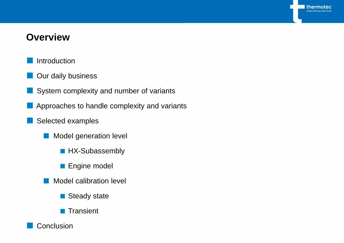
Overview
■ Introduction
■ Our daily business
■ System complexity and number of variants
■ Approaches to handle complexity and variants
■ Selected examples
■ Model generation level
■ HX-Subassembly
■ Engine model
■ Model calibration level
■ Steady state
■ Transient
■ Conclusion

Who is Thermotec?
■ an engineering company - 15 engineers and
.physicists - specialized on thermodynamics and
.fluid mechanics
■ automotive, aerospace and defense industries
■ simulation: thermal/hydraulic systems, thermal
.management and cooling .systems
(1D and 3D-CFD)
■ test benches: wind tunnel for radiator and heat
.exchanger performance tests
■ our customers:
www.thermotec-es.com

Our Daily Business
■ Analysis of vehicle cooling systems
■ Evaluation of concepts, variants, …
■ Dimensioning of components / complete systems
■ What if … analysis
■ Dimensioning / scaling
■ Pumps, fans (size, operating points, …)
■ Radiators (scaling)
■ Piping (pressure drop diameter, etc.)
■ Comparison of concepts / components …
■ Compare model with experimental data
■ Data pre-processing
■ Steady state and transient
■ Model calibration (experiment, 3D-CFD, …)
■ Evaluation / post-processing / documentation …

Vehicle Cooling System –
From a Simple Model to Complex Systems
and a Huge Number of Variants
Vehicle Cooling System –
From a Simple Model
The Challenge:
■ 1
■ 10
■ 40 – 50
■ 5.000 – 10.000
■ 25.000 – 100.000
■ 1 – 400 x 10 – 100
■ 15.000
Gamma‘s example of a simple
coolant System
(„coolant sytem 1D underhood“)
Facts & model data of a
state of the art
vehicle cooling system model
?
what is necessary and
how will the model look like,
that we can meet
the challenges?

Vehicle Cooling System – State of the Art Main Model Template
Visualization Evaluation
Coolant (HT)
Coolant (NT)
Hybrid-
Module
Driver Vehicle
Gearbox
Engine
Fan
Underhood
Air Flow
Aux. Comp.
el. Engine Air Con
Cond.
HX
HX
HX
HX
HX
HX
HX
HX
HX
HX
HX
HX
HX HX
HX
HX
HX
Tank Pump
Gear Driving Cycle Model Calibration
Air Calibration
Generator
Cabin
Wheel Transfer
Box Differential
Power Train
Clutch
Tire
ECU Thermal Management
Thermostat Oil
Thermostat Coolant Pump
Thermostat Coolant
Driving Strategy
Torque Converter
AC Circuit
Cabin
Eng. Cooling
Friction Eng. Oil C. Structure
Road
Environment
Oil Circuit
option: detailed models can be coupled
Gear Train

Vehicle Cooling System – Model Complexity and Variants
1
10
40 – 50
5.000 – 10.000
25.000 – 100.000
1 – 400 x 10 – 100
15.000
■ Universal GT-Main-Model(-Template)
■ Circuits: coolant (ht, lt,…), oil, air, refrigerant …
■ External subassemblies (placeholders) - main components of vehicle
■ Total number of parts in 1 model
■ Code lines in a „ready-to-simulate“ model file (*.dat-file)
■ Simulations/1night (variants x use cases)
■ Result files (400 variants with 10 use cases)
up to:

Approaches to Handle System Complexity and Number of Variants
■ Automated component-model setup consequently with modular blocks
■ 1 Subassembly for each component
■ Standard nomenclature and interfaces
■ Sub-assemblies can be exchanged easily
■ Optional more detailed models can be coupled
■ Components and main-model as templates
■ Model data provided from external files
■ Model creation via VBA (components, main-model, variants)
■ Automated pre- and post-processing – Excel / VBA
■ Pre-processing of component data and experimental data
■ Collection of results, data reduction
■ Standard reports, diagrams etc.

Examples for Automation
■ Automatic Component-model creation
■ Heat exchanger
■ Engine model
■ Model calibration steady state
■ Pre-processing of experimental data
■ Model calibration transient
■ Pre-processing of experimental data
■ System Identification

Automation – Component Generation: Heat Exchanger
Heat Exchanger
type
dimensions
hydraulic and thermal
performance
properties of matter
Heat Exchanger -
Process Relevant Data
manual step
Template
Data Sheet
automatic step
dimensions
properties of matter
efficiency
- hydraulic
- thermal
correction if necessary
Check
dimensions
height
# tubes
width
depth !
fins: spacing /
thickness
tubes: wall thickness
Scaling
(optional)
Visual Check & Last
Modifications
Generation of
GT-HX-Subassembly
and Automatic Pre-
processing
HX-test bench
Documentation of Nu-
Re-Regression Quality
correction of regression
to meet raw data (option)
add HX-Model to
Component Database

Engine
Automation – Component Generation: Engine–Model
type
variants
parameters
- approx. 100
performance maps
- approx. 50
Engine -
Process Relevant Data
manual step
Template
Data Sheets…
automatic step
.
Template
Performance Maps…
all parameter and data
sheets available?
parameter and data
consistent?
Check
Generation of GT-
engine Subassembly
Modular Internal Sub-
Assemblies
- heat rejection
- charge air
- coolant
- engine oil
- mechanics
- gas exchange cycle
- friction
- thermal mass /
structure
Hydraulic Calibration
(GEM3D, CFD…)
pressure drop water
jacket
Thermal Calibration
(System Identification)
heat rejection: road test
non-linear black-box mod.
0 500 1000 1500 2000 2500 3000 3500-5
-4
-3
-2
-1
0
1
2
3
4
5
6
7
Zeit [s]
T
KM
-Mota
us [
°C]
0 500 1000 1500 2000 2500 3000 35000
50
100
150
200
250
Zeit [s]
Geschw
indig
keit [
km
/h]
Versuch-GT (mod.)
Geschwindigkeit
Versuch-SYSID
add Engine-Model to
Component Database

Automation – Model Calibration
Goal:
■ find measurement errors / uncertainties and model calibration factors for
■ heat flow: heat rejection engine, air cond, gear box, …
■ flow rates: coolant, air, oil, atf, …
■ performance maps: heat exchangers, pumps, …
■ that the model can reproduce the measured temperatures
■ for all (sensor) positions
■ simultaneously and
■ for all use cases
■ as automated as possible

Automation – Model Calibration Steady State
Vehicle
Experiment
steady state
use cases:
wind tunnel
dynamo-
meter
test bench
Measurement errors vs.
CFD uncertainties used for model generation
temperatures
no feasible physical solution
flow rates
heat flow rates
perf. maps
Check &
Process co
nsis
ten
cy
no
me
ncla
ture
ma
tch
diffe
rentd
ata
so
urc
es
Pre-Process
Experimental Data
e.g. find steady state
temperatures when „not
steady state“
end of
experiment
steady
temperature
measured
coolant temp.
regression
Mod.
mo
de
l ge
ne
ratio
n
Cal.
loa
d, h
yd
rau
lic, u
nd
erh
ood flo
w
automatic optimization based
on maximum likelihood
simultaneous correction of
- flow rates
- heat flow rates
- performance maps (HX, …)
calibrated GT-Model
reproducing - in all probability -
correct temperatures at all
(measured) positions and for all
media flows (consistent solution)

Automation – Model Calibration Transient
calibrated GT-Model
reproducing
correct steady
temperatures at all
positions and
for all media flows
Model
Steady State
match GPS vehicle data
to road topology:
road grade, curvature
and
environment conditions:
temperature, pressure…
wind speed and wind
direction, …
Pre-Process
Experimental Data
thermal masses and
engine response, …
System Identification
e.g. Inertia
Google Earth &
GeoContext
global weather data:
wind speed and direction
Topology
.
Merged and Matched
Road & Vehicle Data
circuit segments
speed road grade
System Identification
Heat Rejection Engine
heat rejection @ road test
non-linear black-box or
grey box models
0 500 1000 1500 2000 2500 3000 3500-5
-4
-3
-2
-1
0
1
2
3
4
5
6
7
Zeit [s]
T
KM
-Mota
us [
°C]
0 500 1000 1500 2000 2500 3000 35000
50
100
150
200
250
Zeit [s]
Geschw
indig
keit [
km
/h]
Versuch-GT (mod.)
Geschwindigkeit
Versuch-SYSID
GT-Component
Generation
GT-Simulink Harness
for identified models
e.g.
thermal inertia
engine response
engine heat rejection
calibrated GT-Model
reproducing measured
temperature gradients
Model
Transient
96
98 9898 98
99 9998
97
9898 98
9898
98
92 92
93 93
95
97 96
9798
99
95
97 9798
97
9697 97
9898 98
99
90
102 102
101100
10099
98
96 96
95
97
99
98
95
91
98
99100
101
10099 99
102
99100
101
102
103
9999
98
100
100
90
95
100
105
0 1 2 3 4 5 6 7 8 9 10 11 12 13 14 15 16 17 18 19 20 21
v.Fz
g [k
m/h
]
mittlere Geschwindigkeit/Runde v.Fzg [km/h] GDX F30N55RT
GDX F32B46RT
GDX F30B58RT
GDX F30B58RT
GDX F56B48JCW

Conclusion
■ What is necessary to handle and simulate complex cooling systems and
what is possible with Gamma Technologies GT-Suite?
■ Models / Simulation
■ Very short simulation times / fast covergence
■ Robust models
■ Modelling
■ Automation of model generation (VBA)
■ Component and system-model generation / modification
■ Co-simulation with System Identification / Simulink (SimulinkHarness)
■ Model data: administration in external file(s) or database (Excel)
■ Tools to model specified components very detailed
■ Simulation
■ Automation of pre- and post-processing (VBA, Excel)
■ Automation and organisation of simulation-runs 24/7 workload of server and
licenses (VBA, Excel)
■ Automation of model calibration (VBA and GT)

Thank You for Your Attention!
www.thermotec-es.com