Analysis of Superconducting Fault Current Limiter in DC ... S.Sanjeeva Rayudu, C.Ganesh, B.Vignesh...
12
International Journal of Electrical Engineering. ISSN 0974-2158 Volume 8, Number 4 (2015), pp. 329-339 © International Research Publication House http://www.irphouse.com Analysis of Superconducting Fault Current Limiter in DC System with Renewable Energy Sources S.Sanjeeva Rayudu 1 , C.Ganesh 2 , B.Vignesh Naik 3 1,2 Assistant Professor, 3 PG Student, Department of Electrical & Electronics Engineering, Annamacharya Institute of Technology & Science, Rajampet, Andhra pradesh, INDIA. Abstract Superconducting fault-current limiters (SFCLs) have been the subject of research and development for many years and offer an attractive solution to the problem of rising fault levels in electrical distribution systems. SFCLs can greatly reduce fault currents and the damage at the point of fault, and help improve the stability of a power system. Superconducting fault-current limiters (SFCL) provide a new efficient approach to the reliable handling of such faults.(SCFLs) can be used for various nominal voltages and currents, and can be adapted to particular limiting characteristics in case of short circuits. In this project, dc resistive type superconducting fault current limiter (SFCL) is presented. This SFCL is designed for the HVDC system. Uniform current and voltage sharing among the SFCL modules can be observed through contact resistance tests, dc flow-through tests, and ac flow-through tests. Results of tests show that each limiting module has good uniformity in higher current system. The proposed concept can be implemented using renewable energy sources.The results are presented by using Matlab/simulink platform. Index Terms— DC system, resistive-type superconducting fault current limiter (SFCL), short circuit current, uniformity, renewable energy sources. I. INTRODUCTION Dc power systems are widely used because of its flexible, low maintenance cost and fast transient capability. However, for bulk power transmission over long distances high voltage dc (HVDC) transmission lines are preferred. Due to the high power capacity, reliable and safety performance are critical for such dc systems. Size of
Transcript of Analysis of Superconducting Fault Current Limiter in DC ... S.Sanjeeva Rayudu, C.Ganesh, B.Vignesh...
International Journal of Electrical Engineering.
ISSN 0974-2158 Volume 8, Number 4 (2015), pp. 329-339
© International Research Publication House
http://www.irphouse.com
Analysis of Superconducting Fault Current Limiter
in DC System with Renewable Energy Sources
S.Sanjeeva Rayudu1, C.Ganesh
2, B.Vignesh Naik
3
1,2 Assistant Professor,
3 PG Student,
Department of Electrical & Electronics Engineering,
Annamacharya Institute of Technology & Science, Rajampet,
Andhra pradesh, INDIA.
Abstract
Superconducting fault-current limiters (SFCLs) have been the subject of
research and development for many years and offer an attractive solution to
the problem of rising fault levels in electrical distribution systems. SFCLs can
greatly reduce fault currents and the damage at the point of fault, and help
improve the stability of a power system. Superconducting fault-current
limiters (SFCL) provide a new efficient approach to the reliable handling of
such faults.(SCFLs) can be used for various nominal voltages and currents,
and can be adapted to particular limiting characteristics in case of short
circuits. In this project, dc resistive type superconducting fault current limiter
(SFCL) is presented. This SFCL is designed for the HVDC system. Uniform
current and voltage sharing among the SFCL modules can be observed
through contact resistance tests, dc flow-through tests, and ac flow-through
tests. Results of tests show that each limiting module has good uniformity in
higher current system. The proposed concept can be implemented using
renewable energy sources.The results are presented by using Matlab/simulink
platform.
Index Terms— DC system, resistive-type superconducting fault current
limiter (SFCL), short circuit current, uniformity, renewable energy sources.
I. INTRODUCTION
Dc power systems are widely used because of its flexible, low maintenance cost and
fast transient capability. However, for bulk power transmission over long distances
high voltage dc (HVDC) transmission lines are preferred. Due to the high power
capacity, reliable and safety performance are critical for such dc systems. Size of
330 S.Sanjeeva Rayudu, C.Ganesh, B.Vignesh Naik
conductor in dc transmission can be reduced as there is no skin effect. However, for
large-power transmission over long distances, HVDC turns out to be economical. In
order to achieve safety performance, fault protection and tolerance are usually
required. In dc grids, the fault current has no zero crossing point as the ac current
does. So it is difficult to open the over current fault transmission line.
Superconducting fault current limiter (SFCL) is one of the most ideal current limiting
devices to protect the system and electrical equipments. It can limit the fault current
effectively in power systems and prevent damage to the circuit components within
several milliseconds. Over the years, HVDC transmission has been constantly
developing in China. Multiple HVDC transmission lines have been built in China [1],
[2]. With the increase of power system capacity and the development of transmission
technique, the short circuit current will reach the peak current which ranges between
kiloampere and tens of kiloamperes within several milliseconds.
At present, using circuit breakers to cut off the fault current is widely applied in the dc
system to ensure the whole system safety. However, the rated ultimate breaking
capacity is limited, which will not meet the requirement of constant increase in short
circuit current level. Recently, the dc breaker developed by ABB can cut off a 16 kA
fault current within 2 ms while its rated voltage is 320 kV [3], and Alstom has
developed a dc breaker that can cut off a 7.5 kA fault current within 1.6 ms while the
rated voltage is 120 kV [4]. The SFCL could bring a solution to the main bottleneck
of the dc networks and the interruption of the fault current.
Most of the SFCL prototypes up to now have been designed for ac systems [5]-[8].
This paper introduces a dc SFCL prototype. This resistive type SFCL prototype has
been designed and constructed by Shanghai Jiao Tong University. The prototype will
be applied in an isolated dc network as an Ingrid demonstration to prove the current
limiting ability of SFCL in dc systems. In this paper, renewable energy sourse can be
applied at the input side. HVDC can connect remote sources of electrical power often
emissions-free renewable energy sources like hydro or wind generation to load
centres where it is needed, hundreds or even thousands of kilometers away.
For a real gird demonstration, the utilities require the SFCL to provide good current
limiting performance. So the HTS tapes are chosen based on their characteristics.
Then simulations are carried out to optimize the limiting effect and determine the
SFCL parameters. A series of experiments are conducted to test the characteristics of
a single module and the whole SFCL prototype before demonstration.
II. HIGH TEMPERATURE SUPERCONDUCTOR TAPES TEST
A high power dc short circuit test platform is built to verify the limiting effect of the
second generation (2G) high temperature superconductor (HTS) tapes in dc power
systems. The platform is composed of a step-down transformer, an uncontrolled
rectifier bridge and a short-circuit control circuit, as shown in Fig. 1.

Analysis of Superconducting Fault Current Limiter in DC System
with Renewable Energy Sources 331
331
Fig. 1. Overall test platform.
The system voltage is provided by an isolated transformer which has variable
secondary 20/40/100 VAC. The low voltage level is good for the safety of the test
system, so the experiments are conducted when the voltage is 20 VAC and 40 VAC.
So the dc voltage behind the rectifier bridge is about 28 V and
56 V. Without the superconducting limiting module, the normal current and the short
circuit current are, respectively 6.7 A and 1750 A when the transformer provides 20
VAC signals; and they are, respectively 13.3 A and 3150 A when the transformer
provides 40 VAC signals. Because of the capacitor and resistors of release circuit, the
fault current is not linear.
Superconducting limiting module of two types of HTS tapes, respectively produced
by the Physics Department of Shanghai Jiao Tong University (SJTU) and American
Superconductor Corporation (AMSC), are applied to the dc system to prove the
current limiting ability of superconducting materials. The critical currents of both two
types of HTS tapes are 250 A. The length of HTS tapes consisted in the limiting
module are 6 meters. The parameters of two types of HTS tapes are shown in Table I.
Short circuit experiments with the limiting module are conducted when the
transformer supplies 20 VAC and 40 VAC. The circuit current is obtained by testing
the voltage of the line resistor. The duration of short circuit is 100 ms. Short circuit
current and the resistance of the superconducting limiting module in 20 VAC and 40
VAC systems are shown in Fig. 2.

332 S.Sanjeeva Rayudu, C.Ganesh, B.Vignesh Naik
Fig. 2. (a) Short circuit current. (b) Resistance of the super-conducting limiting
module.
Some characteristics of limiting effect in the dc system are got from the experiments,
as shown in Table II.
From Fig. 2 and Table II, we observe that superconducting materials also have the
ability of limiting current in dc systems. The SJTU tape is narrower and thinner than
that produced by AMSC, so it has larger room temperature resistance and the fault
current in the circuit with SJTU tapes is smaller. However, the AMSC tape has better
heat dissipation because of its thicker stabilized copper layer. Besides, SJTU tape has
a bigger n value, leading to a faster quench response. It is also observed that both
SJTU and AMSC tapes could limit the fault current before the current reaches the
peak value.

Analysis of Superconducting Fault Current Limiter in DC System
with Renewable Energy Sources 333
333
Fig. 3. Structure of a single current limiting module.
Fig. 4. (a) Structure of the whole SFCL module. (b) Real SFCL module.
III. DESIGN OF SFCL MODULE
Based on the HTS tapes tests in Section II, super-conducting materials are proved to
have the limiting ability in dc network. This part will introduce a dc SFCL prototype
which will be applied into a real isolated dc network. The critical current should not
only be greater than the normal current, but also have a certain safety margin. So
according the real isolated DC system, the critical current of the SFCL module is set
as 5 kA. Considering the voltage tolerance of YBCO coated conductors [9], the length
of the HTS tapes in series is set as 66 m.
Double-insert YBCO tapes produced by AMSC are used in the SFCL prototype to
save the module space. The critical current of the double-insert YBCO tapes is 500 A,
so 10 modules are needed to meet the requirement of 5 kA critical current. The
structure of a single current limiting module [10] is shown in Fig.3. Each module
contains 116 pieces of 0.57 m long YBCO tapes which are connected in a
combination of series and parallel. Every 58 YBCO tapes are connected in series to
form one current path at one side of G10 former and two paths are connected in
parallel. Every two tapes are soldered together at the ends with a short YBCO tape
and are fixed on the G10 former with copper terminals.
There are totally 33 m long YBCO tapes in series and two current paths in one
limiting module. The SFCL module needs 66 m long YBCO tapes in series and 10

334 S.Sanjeeva Rayudu, C.Ganesh, B.Vignesh Naik
paralleled branches. So the whole SFCL module is designed as shown in Fig. 4(a) and
the real SFCL module is shown in Fig. 4(b). It consists of two parts in series and each
part has 5 G10 formers in parallel which have 10 paralleled tapes.
The performances of a single module and the laboratory test of the whole SFCL
prototype have been fully conducted and the results will be presented in the paper.
And in-gird test will start in October 2013.
IV. MODULE TESTS
A. Contact Resistance Test for a Single Module
There are 10 limiting modules in parallel in this SFCL. If the current is not equally
distributed and one module has higher current than others, the current path quenches
first and others follow even without fault. Unbalanced current distribution may
lead to a disaster during the normal operation. So the contact resistance of current
paths has to be measured to ensure the uniformity of the current of each limiting
module. Contact resistances of 20 current paths are shown in Table III.
Table III shows that contact resistances of most current paths are between 0.10 mΩ to
0.12 mΩ. Some of the contact resistances are a little larger because of the soldering
technique. The maximum and minimum contact resistances are, respectively 0.163
mΩ and 0.101 mΩ.
To solve the uniformity problem, the data of contact resistances has been optimized.
20 current paths are divided into pairs. Each pair of current paths has similar value of
contact resistance and is treated as the two sides of a limiting module. For example,
path 10 and path 20 sharing the biggest value are chosen to form the two sides of a
limiting module with the biggest contact resistance. Then the ten limiting modules are
divided into two groups. Five of them having a larger contact resistance are in a group
and labeled as part I. And then the others with a smaller contact resistance are in a
group and labeled as part II. In this way, the current uniformity of each limiting
module is improved. The maximum and minimum contact resistances of a single
limiting module are about 0.081 mΩ and 0.052 mΩ, respectively.
To analyze the distribution of dc current, some calculations are performed on the basis
of such module contact resistances. The modules with the biggest and smallest contact
resistances account for about 16.05% and 22.03% of the total current, respectively.
The percentage difference is 5.98%.

Analysis of Superconducting Fault Current Limiter in DC System
with Renewable Energy Sources 335
335
Fig. 5. Distribution of the dc current.
B. DC Flow-Through Test
The SFCL module is assembled after the 10 limiting modules have been optimized
and grouped. In order to test the current uniformity of each limiting module in liquid
nitrogen (LN2), the dc flow-through test is carried out for the whole SFCL module.
Different dc currents are applied to the whole SFCL module in LN2. We use multi-
channel data acquisition system to measure the current of every limiting module. The
current is shown in Fig. 5.
Fig. 5 shows that the currents of most modules are similar. The maximum and the
minimum values of the currents are shown in Table IV.
From the Table IV, it is observed that the percentage difference is about 6.1%. This
percentage difference of experiments is a little bigger than that in part A by
calculation because contact resistance also contains the joint resistance between
limiting modules and the copper current bus. This contact resistance brings more
unbalanced current.
According to the system current and the percentage difference in Table IV, the
difference between the maximum and minimum currents of limiting modules is about
152.5 A. The maximum current of a single limiting module with two current paths is
about 595 A, which is safe to YBCO tapes. And the difference of currents is
acceptable for the whole SFCL.
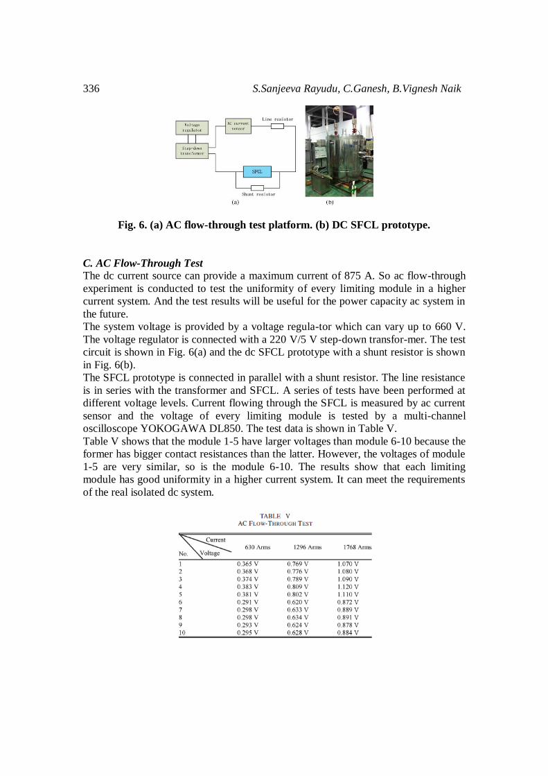
336 S.Sanjeeva Rayudu, C.Ganesh, B.Vignesh Naik
Fig. 6. (a) AC flow-through test platform. (b) DC SFCL prototype.
C. AC Flow-Through Test
The dc current source can provide a maximum current of 875 A. So ac flow-through
experiment is conducted to test the uniformity of every limiting module in a higher
current system. And the test results will be useful for the power capacity ac system in
the future.
The system voltage is provided by a voltage regula-tor which can vary up to 660 V.
The voltage regulator is connected with a 220 V/5 V step-down transfor-mer. The test
circuit is shown in Fig. 6(a) and the dc SFCL prototype with a shunt resistor is shown
in Fig. 6(b).
The SFCL prototype is connected in parallel with a shunt resistor. The line resistance
is in series with the transformer and SFCL. A series of tests have been performed at
different voltage levels. Current flowing through the SFCL is measured by ac current
sensor and the voltage of every limiting module is tested by a multi-channel
oscilloscope YOKOGAWA DL850. The test data is shown in Table V.
Table V shows that the module 1-5 have larger voltages than module 6-10 because the
former has bigger contact resistances than the latter. However, the voltages of module
1-5 are very similar, so is the module 6-10. The results show that each limiting
module has good uniformity in a higher current system. It can meet the requirements
of the real isolated dc system.

Analysis of Superconducting Fault Current Limiter in DC System
with Renewable Energy Sources 337
337
Fig. 7. Simulation model of the dc network.
V. MODELING AND SIMULATION
Before the Ingrid test, simulations are carried out to research the current limiting
effect. The dc network is built in Matlab/simulink based on the real parameters of the
isolated system. The SFCL model [11] is used in the system to simulate its impact on
the dc network. The simulation model in Matlab/simulink is shown in Fig. 7.
A series of simulations are carried out to determine the value of shunt resistor. The
room temperature resistance of SFCL is about 0.452 Ω. So the value of shunt resistor
should be around 0.5 Ω. The current limiting effects of different shunt resistors are
shown in Table VI.
Considering the limiting effect and the cooperation with other electrical equipments,
the shunt resistor in parallel with the superconductor is set as 0.6 Ω to adjust the
limited current and to avoid the over-voltages.
The dc system is stable at t = 0.7 s. Simulations are carried out with the short-circuit
fault happened at t = 0.8 s (t = 0 s at the beginning of the simulation), and the fault
will be clear at t = 1.0 s. The total simulation time is 200 ms. Short circuit currents
with and without SFCL are shown in Fig. 8.
Fig. 8. (a) Short circuit current curves with and without SFCL. (b) Rising edge of
short circuit current curves with and without SFCL.

338 S.Sanjeeva Rayudu, C.Ganesh, B.Vignesh Naik
The short circuit currents in Fig. 8(a) are damped oscillation curves because of the
large inductance and large capacitor behind the rectifier bridge used to stabilize the dc
current and voltage. From Fig. 8(a), it is observed that the short-circuit current is
significan-tly limited by SFCL. The response time of SFCL is about 1.5 ms, as shown
in Fig. 8(b). The peak value of fault current is limited to about 50% of the fault
current without SFCL within 2 ms.
The simulation results show SFCL has the current limiting ability in the real isolated
dc network and will provide the important reference for the field test in Ingrid
demonstration.
VI. CONCLUSION
The design and analysis of a dc SFCL with renewa-ble energy source has been
introduced in this paper. A series of tests of HTS tapes produced by SJTU and
AMSC are carried out to test the tape characteristics and to prove the current limiting
ability of supercon-ducting materials. SFCL modules are assembled tog-ether through
optimizing the contact resistance data of 10 limiting modules. DC and AC flow-
through tests are carried out to measure the uniformity of each limiting module. The
test results show that the module uniformity can meet the requirements of the real
isolated dc network. Based on the test data, simulations are performed to research the
impact of SFCL on a real dc system and determine the SFCL parameters suitable for
the network. Simulation results indicate that the dc SFCL needs 66 m YBCO tapes in
series and 10 limiting modules in parallel.
The SFCL with a 0.6 Ω shunt resistor is able to reduce the fault current to 50.76% of
the original value.
REFERENCES
[1] Y. Huang and Z. Xu, “Study on the pure dc transmission scheme for China’s
future power transmission form the west to east,” in Proc. IEEE Power Eng.
Soc. Gen. Meet., 2004, pp. 1459-1463.
[2] H. Huang, Z. Xu, W. Wang, and C. Wang, “Transient stability analysis of
shanghai power grid with multiple HVDC links,” in Proc. Int. POWERCON
Syst. Technol., pp. 1-6.
[3] L. Xiao, S. Dai, L. Lin, Z. Zhang, and J. Zhang, “HTS power technology for
future DC power grid,” IEEE Trans. Appl. Supercond., vol. 23, no. 3, p.
5401506, Jun. 2013.
[4] G. F. Tang, “Multiple-terminal DC power transmission and DC power grid
technology,” presented at the Fragrant Hill Sci. Meeting, Beijing, China, Sep.
27-29, 2012.
[5] L. Ye and L. Lin, “Study of superconducting fault current limiters for system
integration of wind farms,” IEEE Trans. Appl. Supercond., vol. 20, no. 3, pp.
1233-1237, Jun. 2010.

Analysis of Superconducting Fault Current Limiter in DC System
with Renewable Energy Sources 339
339
[6] O. B. Hyun, H. R. Kim, J. Sim, Y. H. Chung, K. B. Park, B. W. Lee, and I. S.
Oh, “6.6 kV resistive superconducting fault current limiter based on YBCO
films,” IEEE Trans. Appl. Supercond., vol. 15, no. 2, pp. 2027-2030, Jun.
2005.
[7] L. Martini, M. Bocchi, M. Ascade, A. Valzasina, V. Rossi, C. Ravetta, and G.
Angel, “Live-grid installation and field testing of the first Italian
superconducting fault current limiter,” IEEE Trans. Appl. Supercond., vol. 23,
no. 3, p. 5602504, Jun. 2013.
[8] H. Shin, S. Cho, J. Huh, J. Kim, and D. Kweon, “Application on of SFCL in
automatic power changeover switch system of electric railways,” IEEE Trans.
Appl. Supercond., vol. 22, no. 3, p. 5600704, Jun. 2012.
[9] M. Noe, A. Hobl, P. Tixador, L. Martini, and B. Dutoit, “Conceptual design of
a 24 kV, 1 kA resistive superconducting fault current limiter,” IEEE Trans.
Appl. Supercond., vol. 22, no. 3, p. 5600304, Jun. 2012.
[10] Z. Hong, J. Sheng, J. Zhang, B. Lin, L. Ying, Y. Li, and Z. Jin, “The
development and performance test of a 10 kV resistive type superconducting
fault current limiter,” IEEE Trans. Appl. Supercond., vol. 22, no. 3, p.
5600504, Jun. 2012.
[11] Y. Chen, S. Li, J. Sheng, Z. Jin, Z. Hong, and J. Gu, “Experimental and
numerical study of co-ordination of resistive-type superconductor fault current
limiter and relay protection,” J. Supercond. Novel Magn., vol. 26, no. 11, pp.
3225-3230, Nov. 2013.
S.SANJEEVA RAYUDU has been working as assistant professor in the stream of
Electrical and Electronics Engineering at “Annamacharya institute of technology
and science” Rajampet, kadapa (dist). His area of interests are power systems, power
Electronics and advanced power engineering concepts etc,.
C.GANESH has been working as assistant professor in has been working as assistant
professor in the stream of “Annamacharya institute of technology and science”
Rajampet, kadapa (dist). His area of interests are power systems, power Electronics
etc,.
B.VIGNESH NAIK has been pursuing his Master of Technology in Electrical and
Electronics Engineering from “Annamacharya institute of technology and science”
Rajampet, kadapa (dist). His area of interests are Renewable energy sources, power
systems etc,.

340 S.Sanjeeva Rayudu, C.Ganesh, B.Vignesh Naik