Analysis of Friction Torque in Simple OF FRICTION TORQUE IN SIMPLE AND PRELOADED SPUR GEAR TRAINS...
16
NRL Report 6319 Analysis of Friction Torque in Simple and Preloaded Spur Gear Trains J. W. TITUS Equipment Research Branch Radar Division FOR FDp A ''7;? .. . .. .. X"-',[ ( C'' A WINN~E Or October 22, 1965 BEST A AVAILABLE COPY U.S. NAVAL RESEARCH LABORATORY Washingtons D.C.
Transcript of Analysis of Friction Torque in Simple OF FRICTION TORQUE IN SIMPLE AND PRELOADED SPUR GEAR TRAINS...
NRL Report 6319
Analysis of Friction Torque in Simpleand Preloaded Spur Gear Trains
J. W. TITUS
Equipment Research BranchRadar Division
FOR FDp A ''7;?.. . .. . .X"-',[ ( C'' A
WINN~E Or
October 22, 1965
BEST A
AVAILABLE COPY
U.S. NAVAL RESEARCH LABORATORYWashingtons D.C.

CONTENTS
Abstract iiProblem Status iiAuthorization
INTRODUCTION 1
FRICTION TORQUE IN A SINGLE GEAR MESH ASFOUFn ) IN A SIMPLE GEAR TRAIN 1
Approach Action 1Recess Action 3Comparison of Friction Torques in Approach and
Recess Action 5Comment on the Relation of Other Published Analyses
to This Work 5
FRICTION TORQUE IN A FOUR-SQUARE GEAR TRAINREPRESENTATIVE OF BIASED, SPLIT GEAR TRAINS 6
Both Meshes in Approach Action 7One Mesh in Approach Action and the Other
in Recess Action 8Both Meshes in Recess Action 9Maximum Driving Torque 9Application to Design Calculation 10
REFERENCES 11

ABSTRACT
The first part of this study develops the relation between the re-quired drive torque and the load torque in a lightly loaded, single gearmesh, considering Coulomb friction between the sliding tooth surfaces.Bearing and windage losses are not considered. All of the load is as-sumed to be carried on a single pair of teeth, since for lightly loadedgears elastic deflections will be smaller than tooth-to-tooth errors, sothat a single pair of teeth may carry the load regardless of the theoret-ical contact ratio. The use of "efficiency" formulas given in the litera-ture usually gives low values for starting torque requirements.
The second part of the study extends the equations to a four-squaregear train as representative of preloaded split gear trains, where fric-tion losses are relatively greater than in simple trains. It is demon-strated that the maximum possible friction loss for a given four-squaregear train would occur when and if the two gear meshes simultaneouslybegin approach action. It is also demonstrated that the friction loss fora gear train using spring-loaded split gears cannot exceed values cal-culated on the assumption that one mesh begins approach action whilethe other mesh terminates recess action.
PROBLEM STATUS
This is an interim report on one phase of the problem; work on thisand other phases is continuing.
AUTHORIZATION
NRL Problem R05-04AProject RF 008-04-41-4500
Manuscript submitted July 2, 1965.
ii

ANALYSIS OF FRICTION TORQUE IN SIMPLEAND PRELOADED SPUR GEAR TRAINS
INTRODUCTION
The well-known analyses of the efficiency of a gear mesh published by Buckingham(1), Merritt (2), Shipley (3-5), and Tso (6) are primarily concerned with power losses.In this report, attention will be directed toward gear trains for data transmission andother uses where loads are light, and power loss, per se, is of minor importance. De-signers of gear trains for data transmission, instruments, small servomechanisms, etc.,are concerned with starting torque, since this directly affects spring-loading or biasrequirements, and may often be the major load on a mechanical system. The use ofstandard formulas for friction power losses usually gives overoptimistic estimates ofthe starting torque requirements for gear trains.
The first part of this report will develop the friction torque relations in a single,lightly loaded gear mesh, with an effort to promote a clear understanding of the physicalrelationships. The second part extends the results to preloaded gear trains. It will beseen that torque required to overcome gear friction varies as gears rotate in mesh. Theworst possible cases for friction will be emphasized throughout this paper, since designwill usually have to provide for starting in just such a position. The symbols used followBuckingham's notation so far as convenient.
FRICTION TORQUE IN A SINGLE GEAR MESH
AS FOUND IN A SIMPLE GEAR TRAIN
Approach Action
Figure 1 shows a single gear mesh with the upper gear turning clockwise to drive afollower. The subscript I is used on the symbols referring to the driver, and the sub-script 2 on the symbols referring to the follower. The subscript a refers to approachaction, with the point of contact approaching P along vz. The symbols are as follows:
leb, = radius of base circle of driver (in.)
lb2 = radius of base circle of follower (in.)
vz = the path of contact, of the gear mesh, with i' the point of first contact and zthe point of last contact
u\ = a common tangent between the base circles
= the pressure angle of the basic rack
R0o = radius to tip of tooth of driver (in.)
/?oo = radius to tip of follower (in.)
/ = coefficient of friction
f - 1

2 NAVAL RESEARCH LABORATORY
\ItI = normal tooth load (ib)L01 I la = lever arm of friction force acting on driver
during approach (in.)
La) = lever arm of friction force acting on follower" during approach (in.)
rNai = Torque exerted by driver during approach(in. -lb)
Ta2 = Torque exerted on follower during approach. " (in. -lb)Rb 2 R02
m = gear ratio = N'N 1 .
SLa2 The assumptions are as follows:
1. The teeth are involute form.
2. The friction force acts to oppose relativesliding between gear surfaces.
Fig. I - Single gear mesh 3. The magnitude of the friction force is pro-during approach action (point portional to the normal tooth force It;, and is inde-of c o n t a c t approaching p pendent of the sliding velocity except as noted.along 11Z)
4. The mesh is "lightly loaded." This meansthat elastic deflections will be smaller than thetooth-to-tooth errors. A corollary of this assump-
tion, then, is that a single tooth may carry the entire load on the gear mesh regardlessof the theoretical contact ratio.
With the teeth meshing in the approach position shown, the normal force W,, opposesthe rotation of the driver, while the frictional force f I; exerts a moment in the directionof rotation. That is,
7a -bI f I "Lai = ,, 1b - fL.a, (1)
A free-body diagram of the driver is shownin Fig. 2.
Similarly, the normal force and the frictionforce on the follower tooth ar oly opposing torques
To Iduring the approach action of the tooth. Equatingthese torques to the external load torque on the
1, follower, we obtainL G1 R
S,, 2 7 11 .-',, - ,,'nLa2 = ', ( R1b 2 - f/"a,2 (2)
LINE OF ACTION
nThen, from Eqs. (1) and (2), we obtain
fW 7'aI RbI - fLalr7, z _b /° (3)
a2 -e f Lil2 ()Fig. 2 - Free-body diagram ofthe driver gear during approach Maximum friction torque is our main concern.action For a given gear ratio, this means maximum ratio

NAVAL RESEARCH LABORATORY 3
of driver torque to follower torque. Since the coefficient f is being treated as a constant(assumption 3), the right-hand side of Eq. (3) will be maximum when La I is a minimumand La2 a maximum. These conditions occur simultaneously at the beginning of the ap-proach motion, at point V in Fig. 1.
By inspection of Fig. I
L, 2 -- = 1 NIR2 - ; #2°ma I
o LJ UX - IGI (R I 4 I?2) sin 0 - R5)a in 1 2 2 b
The maximum torque ratio may be found by using Eqs. (4) and (5) in Eq. (3).
If torque efficiency is defined as the ratio of the actual output torque to that whichwould be obtained with zero friction, we have
eft . - T2 Rb2 - 2 (6)effiiency m--,a m(,bl a f 1 )
Let 7/ and T12 be the friction torque, that is, the torque loss referred to driver
and to follower speed, respectively:
T/,2 rTal -Ta 2
Tf I To IT- 2 TI 2(7)T Ttot
Using Eq. (3), we obtain
T -2 = T (m -R fL") (8)R 1 -b fL. 1
A more compact expression for 7"' can be obtained in terms of wvn by using Eqs. (1)
and (2) in Eq. (7):
T,, = fB'n(l, a 2 -mLa,)
Maximum friction torque is obtained by using Eqs. (4) and (5):
a/2 ,, = fI',(M+ ')S
where S -/,-, - sin 4 = length of path of approach p.
Recess Action
Equations (1) through (3) apply only to approach action. Recess action will now beconsidered. The gear mesh of Fig. 1 is shown rotated to a position of recess action inFig. 3. A free-body diagram of the driver is shown in Fig. 4 (neglecting bearing reac-tions). Note that the direction of the friction force is reversed from its direction duringapproach. Again we equate the moments of the forces acting on the teeth to the externaltorque on the respective gears:

4 NAVAL RESEARCH LABORATORY
X Fig. 3 - S-ngle gear mesh during re-cess action (point of contact recedingfrom P along VZ)
Fig. 4 - Free-body diagram L, Tri
of the driver gear during R bl
recess action
k fWn
T.I = 1"'n. RbI + f L. ) (9)
T, 2 = "In (6b2 + fLr 2 ) (10)
-" = b L (11)
Tr2 R b2 + l-r2"
Maximum friction torque, which implies maximum ratio of T,. to Tr 2 is still ourmain concern. Again considering f a constant, the maximum value of T I 'IT,2 will cor-respond to a maximum value for Lr I and a minimum for 'r2. It can be seen from Fig. 3that these conditions occur simultaneously at point z, the terminal point of recess action.At this point,
L 1 z - (12)
L, ZX (, +14) sin R - (13)mln1 2 A i b

NAVAL RESEARCH LABORATORY 5
Comparison of Friction Torques in Approach and Recess Action
For ordinary values of f, namely, from zero to 0.4, Eq. (3) gives a larger answerthan Eq. (11). This means that, for a given value of f, the maximum torque required toovercome friction is somewhat greater in approach action than in recess action. If thevalue of f is actually greater during approach than during recess, as Buckingham (1)stated, the difference in torque is even greater than indicated by the comparison of theseequations.
Inspection of Eq. (3) or Fig. 1 reveals that for a sufficiently high value of f, namely
6b 2/L42 , the follower gear would lock up, because the moment exerted by the normal toothforce would be opposed by an equal moment exerted by the friction force on the tooth.Needless to say, such high values of f would not be expected in practice.
Comment on the Relation of Other Published Analysesto This Work
The relations published for gear-mesh power efficiency by Buckingham (1), Merritt(2), and Shipley (4) differ slightly one from another in details. Merritt obtains an "in-stantaneous efficiency" by reasoning which neglects the difference between approach andrecess action. This is essentially the same quantity called "torque efficiency" herein,given by Eq. (6). Assuming that the tooth load at the point of contact is constant, Merrittthen" integrates along the path or contact (vz in Figs. I and 3) to obtain overall power ef-ficiency. Instead of making Merritt's physical assumptions, one may obtain his equationfor "instantaneous efficiency" from Eq. (6) of the present report by using the first twoterms in a series expansion of the right-hand side and then neglecting the term containingthe factor f 2 .
Buckingham gives an analysis which he credits to W. H. Clapp wherein the total workinput to the follower is determined. The work efficiency or power efficiency is then thequotient of this quantity divided by the work input to the driver. Buckingham stressesthe difference between approach and recess action, which Merritt considers "negligible."The relations given as Eqs. (3) and (11) are implicit in Buckingham's work. Shipley'sanalysis is similar to that of Merritt, whose work he lists among his references. Shipley'sequations are given in the authoritative "Gear Handbook" (5). If any of the "efficiencyformulas" mentioned be used for estimating maximum friction torque, the result obtained,for a given value of f, will be roughly 50 percent of the maximum values obtained usingEq. (8). This occurs because the calculation of work or power loss involves integrationof triangular areas whose maximum altitude is proportional to the maximum frictiontorque.
All three authors assume, in effect, that each cycle of tooth engagement correspondsto the passage of a point of contact from end to end of the line of contact and that all ofthe load is carried on a single pair of teeth. Tso and Prowell (6) work out more generalequations for friction power loss and efficiency which take into account the ideal distribu-tion of load between teeth for any contact ratio. Their work does not allow, however, forthe gearing errors which affect this distribution, namely, tooth spacing or pitch varia-tion, profile error, and tooth thickness variation. For lightly loaded fine-pitch gears, itis easily shown that these errors are large compared with the tooth deflections that wouldserve to equalize loads. Thus, the assumption that all of the load is carried on a singlepair of teeth is more realistic for the purposes of this report.
6 NAVAL RESEARCH LABORATORY
FRICTION TORQUE IN A FOUR-SQUARE GEAR TRAINREPRESENTATIVE OF BIASED, SPLIT GEAR TRAINS
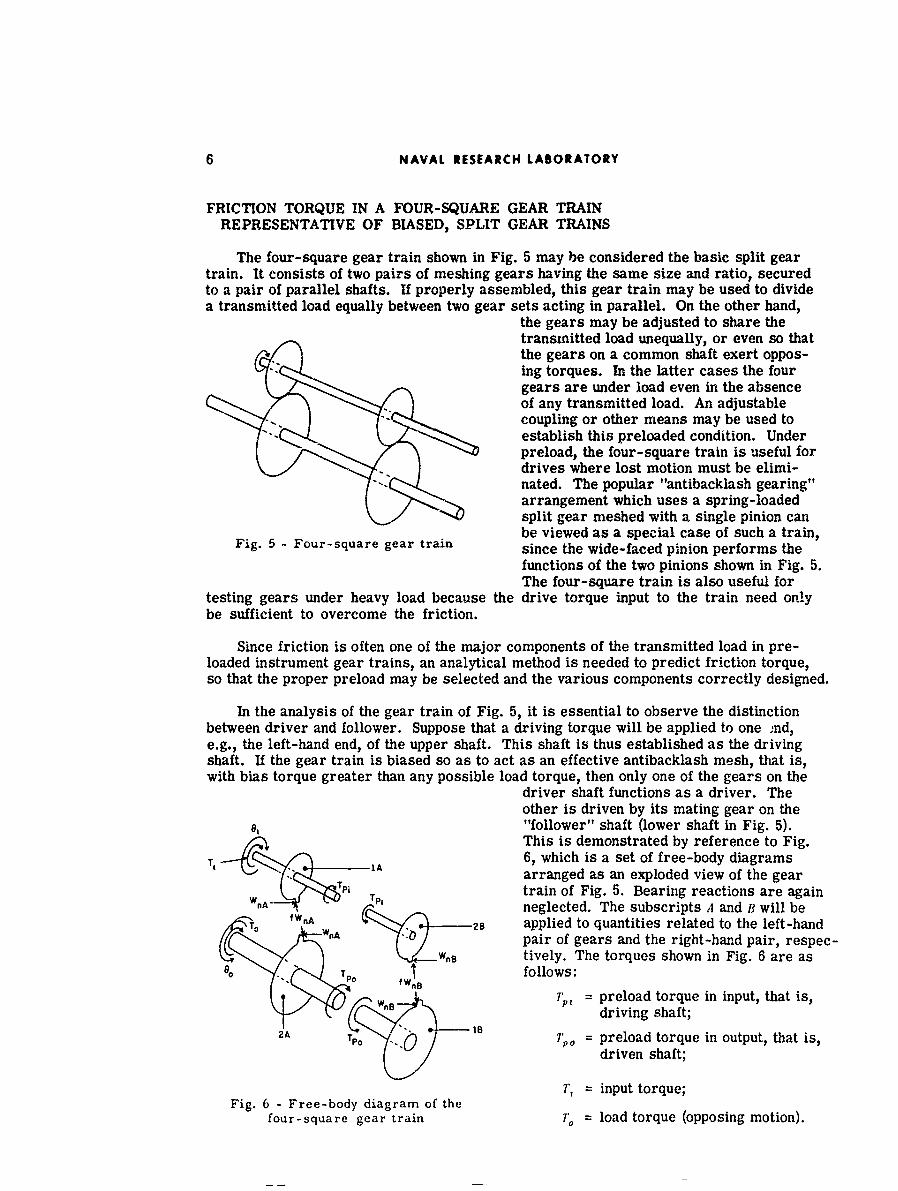
The four-square gear train shown in Fig. 5 may be considered the basic split geartrain. It consists of two pairs of meshing gears having the same size and ratio, securedto a pair of parallel shafts. If properly assembled, this gear train may be used to dividea transmitted load equally between two gear sets acting in parallel. On the other hand,
the gears may be adjusted to share thetransmitted load unequally, or even so thatthe gears on a common shaft exert oppos-ing torques. In the latter cases the fourgears are under load even in the absenceof any transmitted load. An adjustablecoupling or other means may be used toestablish this preloaded condition. Underpreload, the four-square train is useful fordrives where lost motion must be elimi-nated. The popular "antibacklash gearing"arrangement which uses a spring-loadedsplit gear meshed with a single pinion canbe viewed as a special case of such a train,
Fig. 5 - Four-square gear train since the wide-faced pinion performs thefunctions of the two pinions shown in Fig. 5.The four-square train is also useful for
testing gears under heavy load because the drive torque input to the train need onlybe sufficient to overcome the friction.
Since friction is often one of the major components of the transmitted load in pre-loaded instrument gear trains, an analytical method is needed to predict friction torque,so that the proper preload may be selected and the various components correctly designed.
In the analysis of the gear train of Fig. 5, it is essential to observe the distinctionbetween driver and follower. Suppose that a driving torque will be applied to one nd,e.g., the left-hand end, of the upper shaft. This shaft is thus established as the drivingshaft. If the gear train is biased so as to act as an effective antibacklash mesh, that is,with bias torque greater than any possible load torque, then only one of the gears on the
driver shaft functions as a driver. Theother is driven by its mating gear on the"follower" shaft (lower shaft in Fig. 5).This is demonstrated by reference to Fig.6, which is a set of free-body diagrams
-r, i arranged as an exploded view of the gearPi Ttrain of Fig. 5. Bearing reactions are againW f n8neglected. The subscripts A and B will be
TO WnA 28 applied to quantities related to the left-handwnA pair of gears and the right-hand pair, respec-
w~ tively. The torques shown in Fig. 6 are asT T0 follows:
I wn 7';,, = preload torque in input, that is,driving shaft;
AP ° 0 7o , = preload torque in output, that is,
driven shaft;
7', = input torque;Fig. 6 - Free-body diagram of the
four-square gear train 7"0 = load torque (opposing motion).

NAVAL RESEARCH LABORATORY
Also shown in Fig. 6 are 0i and t% indicating the assumed direction of rotation.
The preload process may be imagined to have been accomplished as follows:
1. The right-hand pair of gears are slipped out of mesh, by moving one of the gearsaxially.
2. The lower gear, i B, is held, while the upper gear, 2B, is wound up in a clockwisedirection.
3. The gears are slipped back into mesh.
For the clockwise rotation 0i indicated in the figure, the left-hand upper gear is adriver, but the right-hand upper gear is a follower. As before, the subscripts i and 2will indicate driver and follower, respectively.
It has been seen that the equations of torque equilibrium for a single mesh dependupon whether the mesh action is approach or recess type. For the four-square gear trainwe then have three cases: both meshes in approach action, one mesh in approach actionand other mesh in recess action, and both meshes in recess action. The conditions underwhich these cases occur will be discussed later.
Both Meshes in Approach Action
First considering the case of both meshes in approach action, the equations of torqueequilibrium are written for the right-hand plane, designated B, using -ie same reasoningused for Eqs. (1) and (2):
ri = 1nB 8b- I iqL 2 8 "'nB" -Lb2B f La28 ) (14)
7' P W0 OR(1bB - l. B)• (15)
Similarly, for plane A, the left-hand plane,
Tj + TPi = W,. (I, 1, - fL. 1 ,,) (16)
V. + TP = Wn (/?, 2A -fL a 2 1) (17)
We will solve for T,, the torque necessary to drive this gear train in the directionshown:
Tj 11' f1 - . ) -fL.,,j) 11 ' b"1 /1.0 B (18)
But, by Eq. (17)
To + TPo05, - f/L,,,
and by Eq. (15)
11 - _ _ _ _ _ _ _
Hence
fL L -L,,,
"-'2J (19)le - , /,, Il .t1I

8 NAVAL RESEARCH LABORATORY
For the ordinary four-square gear train as shown in Fig. 6, assuming all gears cutwith the same nominal pressure angle,
b128 = Rbi A and l =1 'b2 A •
Then Tj may be expressed as
Ti rT, + TPoQ (20)
where
? t[?b - /taAit (21)Rb 2A f L 2A
Q 2 bia - fLaiA '?b1A- fL, 2B (22)Rb2A - fLa 2 b2, - fLaIB
This equation does not express the relation between the parameters in a way easy tovisualize. In order to obtain an expression easier to interpret, each of the quotients in-dicated in Eq. (22) is expressed as a power series. Neglecting the third term and higherterms of the series, and collecting terms, a new expression is obtained:
Q R f(La 2 B LailA) + -- [Rb ' (LA 2 A-- L.Ij) + f(LLI 3 ILa 2 - La IALa 211)] (23)
b 2/1 R1, 2 A
LaR 1 [+ La2A- LaiB If(LaIBLa 2B- La 1,ALa 2A)] (24)Q f __ La28 - Il --. (4Rb 2 A mb 2 A
If the terms multiplied by the factor f2 are disregarded, then, if the gears are timedso that approach action begins simultaneously on both meshes, Qm,, may be simplified to
Qmax (.n 1) -L -, [La2/ a +Lax2 i - in k (25)
where 0 is the center distance of the gears and La2 a and L, 2,? are given by Eqs.(4) and (5).
Q will be maximum, clearly, if La2 A and La2 simultaneously reach a maximum.Whether this can occur will depend upon the relative timing of the gears in plane A andplane B.
One Mesh in Approach Action and the Other in Recess Action
For the next case, it will be assumed that the gears in plane A are in approach actionwhile those in plane B are in recess action. The equations of torque equilibrium forplane B are then similar to Eqs. (9) and (10), bearing in mind that in plane B the gear onthe lower shaft is the driver. On gear 28l we have
1,, 1 28B f8h,2B L ,, 8 ) (26)
On gear i ii we have
1Po 9 (1 ?;' , 1, +f L.,l • (27)
- ~.-. - -- '

NAVAL RESEARCH LABORATORY 9
Using Eq. (16) for gear IA we have
Ti 'A(14 iA - fL0-. ) 1 n-B 1 b 28 + f 1- 2 B) .(28)
Using Eqs. (17) and (27) to eliminate y., and Wa from Eq. (28) we obtain
Tr =oTP + 7r,,Q' (29)
where P is given by Eq. (21) and
Q,: = bl,1- fLal..t _ 1A + fL,2B (30)Rb2 A - fLa 21 1 Rb2A + L3 B
The approximate equation for Q' is obtained in the same way as Eq. (24):
Q f La 2A + L,8 f(L,2BLriB LA 1 LLa 2,,)]Q' - (La)A+L, 2 B) + + -. (31)
TRb 2A 1 R6 2A
Both Meshes in Recess Action
Similar equations can be obtained for the case where both meshes are simultaneouslyin recess action. Since the drivi.ng torque must be greater during approach action, thiscase is less important and will. accordingly not be developed here.
Maximum Driving Torque
Driving torque T, is evidently maximum when and if P and Q or Q' simultaneouslyobtain their maximum values. The conditions for maximum of the term P were given inEqs. (4) and (5). It can be seen that maximum Q or Q' occurs if the second term of theright-hand side of Eq. (22) or Eq. (30), res.pectively, is minimum when P is maximum.
Thus for the case of both meshes in approach action the driving torque Tj would havethe maximum possible value if and when L.2,, and L, 2 , simultaneously have maximumvalue. This situation occurs if both meshes simultaneously initiate thei approach action.(Note that Lai,. and L, ,, will always be minimum when La2 ,1 and La2 y are respectively atmaximum, since L. I + La 2 =T- s in k.) The appropriate values for the L quantities inEqs. (21) and (22) are given by Eqs. (4) and (5).
For the case of mesh A in approach action and mesh B in recess action the drivingtorque Tj would have the maximum possible value if and when L-2,1 and L,, 8 simultane-ously have maximum value. This situation occurs when mesh A begins approach actionand, simultaneously, mesh B terminates recess action. (Note that L,.2, will automaticallybe minimum when L,?B is maximum, since L, + L, 2 cD si n d.) The appropriate valuesfor the L quantities in Eqs. (21) and (30) are given in Eqs. (4), (5), (12), and (13). It canbe shown that this meshing condition will occur if the gear tooth proportions satisfy theequality
To + d' IoA2 21102A ( 2 - R 2 - d n32)
T. + - 2A 1 162 - ,1 (32)
where
't = tooth thickness at the tip of both gear 2A and gear iB,
= circular pitch,
10 NAVAL RESEARCH- LABORATORY
n0, 12,...,
R24 = nominal pitch diameter of gear 2A.
Only a few of the possible gear combinations exactly satisfy this criterion; a muchlarger proportion come fairly close. Thus the estimate of required driving torque ob-tained by using the maximum described will usually be conservative.
Application to Design Calculation
Given the output torque r. for any four-square gear train, a conservative estimateof the required Input torque is obtained by assuming that the train can pass through themaximum value for the case of both meshes in approach action. The input or drive torquecan then be calculated by Eqs. (20), (21), and (22), using the values for the lever arms asgiven by Eqs. (4) and (5). The possibility of this occurrence depends up,-n the timing be-tween the gears in plane A and those in plane B. If this timing is not specified in a splittrain, It would be necessary for a conservative design to assume that this maximum canoccur.
If, however, the four-square gear train under consideration takes the specific formof a set of spring-loaded split gears, then, as noted earlier, pinion 2B is merely an ex-tension of pinion IA. For such an arrangement, the maximum possible drive torque isthe maximum given for the case of mesh A in approach action and mesh B in recess ac-tion by using in Eq. (29) the values for the lever arms given in Eqs. (4), (5), (12), and(13). This maximum could not actually occur unless the design happened to satisfy Eq.(32). For nearly all design applications, however, the conservative answer given wouldhave accuracy consistent with the other design parameters.
A designer might have a real need to minimize friction in a four-square gear train.The present study does not give a systematic solution to such a problem. The previoussection, however, makes it evident that maximum starting friction conditions can beavoided, other things being equal, by avoiding designs which make it possible for the twomeshes to simultaneously begin approach action or for one mesh to begin approach ac-tion while the other mesh terminates recess action (Eq. (32)). Tooth numbers and otherparameters can be chosen so as to approach a minimum condition, using the relationsgiven for guidance and for verification of choice.
A review of the extensive literature on friction coefficients is beyond the scope ofthis report. Note, however, that values of f used to obtain starting torque should behigher than those given in the literature for well-lubricated gearing. Lubrication will beboundary type, at best, since the steady bias torque has time to squeeze out the lubricantwhen the gear train is stationary. If better data are not available, a conservative valueof f = 0.2 is suggested for free-running instrument gear trains with grease lubrication.

REFERENCES
1. Buckingham, E., "Analytical Mechanics of Gears," New York:McGraw-Hill, 1949
2. Merritt, H.E., "Gears," 3rd edition, London:PItman, 1954
3. Shipley, E.F., 'Ilow to Predict Efficiency of Gear Trains," Product Eng. 29fNo. 31):44(Aug. 4, 1958)
4. Shipley, E.F., "Efficiency of the Involute Spur Gear Mesh," American Society of Lu-brication Engineers Gear Symposium, Jan. 1959
5. Shipley, E.F., pp. 14-3 through 14-6 in "Gear Handbook t' edited by D. Dudley, NewYork:McGraw-Hill, 1962
6. Tso, L.N., and Prowell, FW., "A Study of Friction Loss for Spur Gear Teeth," ASMEpaper 61-WA-85, 1961
11

Security Classification
DOCUMENT CONTROL DATA- R&D(.2ecurty c€lesjI eti n Of fill* body of absteact and indexing annotation must be entered wtton the overall report As c4ea31bed)
I OqIGINATING ACTIVIIY (Crporlse author) 2a. REPORT SECURITY C LASSIFI(CATION
U.S. Naval Research Laboratory 2b cRoup UnclassifiedWashington, D.C. 20390
3 REPORT TITLE
ANALYSIS OF FRICTION TORQUE IN SIMPLE AND PRELOADED SPURGEAR TRAINS
4. OESCRIPTIVE NOTES (Type of report and inclusive deess)
Interim report on one phase of the problemS AUTHOR(S) (Lat nwne. first name. Initial)
Titus, James W.
6- REPORT OATE 7- TOTAL NO, OF PAGES J b. NO. Oe REFS
October 22, 1965 16 688 CONTRACT OR GRANT NO 9a ORIGINATOR'S REPORT NUMBER(S)
NRL Problem R05-04AptoircT NO NRL Report 6319RF 008-04-41-4500
c 9b OTHER REPORT NO1S.) (Any othernumbers thct may be assignedLhis report)
d.
10. AVA IL ABILITY/6IMITATION NOTICES
Distribution of this document is unlimited
It SUPPLEMENTARY NOTES 12, SPONSORING MILITARY ACTIVITY
Dept. of the Navy (Office ofNaval Research)
13 ABSTRACT
The first part of this study develops the relation between the required drivetorque and the load torque in a lightly loaded, single gear mesh, consideringCoulomb friction between the slidig tooth surfaces. Bearing and windagelosses are not considered. All of the load is assumed to be carried on a singlepair of teeth, since for lightly loaded gears elastic deflections will be smallerthan tooth-to-tooth errors, so that a single pair of teeth iay carry the load re-gardless of the theoretical contact ratio. The use of "efficiency" formulas givenin the literature usually gives low values for starting torque requirements.
The second part of the study extends the equations to a four-square geartrain as representative of preloaded split gear trains, where friction losses arerelatively greater than in simple trains. It is demonstrated that the maximumpossible friction loss for a given four-square gear train would occur when andif the two gear meshes simultaneously begin approach action. It is also demon-strated that the friction loss for a gear train using spring-loaded split gearscannot exceed values calculated on the assumption that one mesh begins ap-proach action while the other mesh terminates recess action.
DD JAN 1473 13Security Classification

Security Classification4,KYWRSLINK A LINK 8 LINK CKEY WORDS
ROLE WY ROLE WT ROLE WT
GearsAnalysisFrictionDrivesTorqueLoading (mechanics)MomentsRotationInstrumentationServomechanismsData transmission systemsFour-square gear train
INSTRUCTIONSA. ORIGINATING ACTIVITY. Enter the name and address imposed by sec.urit) classification, using standard statementsof the contractor, subcontractor, grantee, Department of De- such as:fense activity or other organization (corporate author) issuing (I) "Qualified requesters may obtain copies of thisthe report. report from DDC."2a. REPORT SECURITY CLASSIFICATION: Enter the over- (2) "Foreign announcement and dissemination of thisall security classification of the report. Indicate whether"Restricted Data" is included. Marking is to be in accord- report by DDC is not authorized."ance with appropriate security regulations. (3) "U. S. Government agencies may obtain copies of
this report directly from DDC. Other qualified DDC2b. GROUP: Automatic downgrading is specified in DoD Di- users shall request throughrective 5200. 10 and Armed Forces Industrial Manual. Enterthe group number. Also, when applicable, show that optionalmarkings have been used for Group 3 and Group 4 as author- (4) "U. S. military agencies may obtain copies of thisized. report directly from DDC. Other qualified users
3. REPORT TITLE: Enter the complete report title in all shall request throughcapital letters. Titles in all cases should be unclassified.If a meaningful title cannot be selected without classifica-tion. show title classification in all capitals in parenthesis (5) "All distribution of this report is controlled. Qual-immediately following the title. ified DDC users shall request through4. DESCRIPTIVE NOTES: If appropriate, enter the type of ."report, e.g., interim, progress, summary, annual, or final. If the report has been furrushed to the Office of TechnicalGive the inclusive dates when a specific reporting period is Services, Department of Commerce. for sale to the public, mdi-covered. cate this fact and enter the price, if known.5. AUTHOR(S): Enter the name(s) of author(s) as shown or. 11. SUPPLEMENTARY NOTES: Use for additional explana-or in the report. Ente last name, first name, middle initial, tory notes.If military, show rank and branch of service. The name ofthe principal author is an ahsolute minimum requirement. 12. SPONSORING MILITARY ACTIVITY: Enter the name of
the departmental project office or laboratory sponsoring (pay-6. REPORT DATE. Enter the date of the report as day, ang for) the research and development. Include address.month, year; or month, year. If more than one date appearson the report, use date of publication. 13. ABSTRACT: Enter an abstract giving a brief and factual
summary of the document indicative of the report, even though7a. TOTAL NUMBER OF PAGES: The total page count it may also appear elsewhere in the body of the technical re-should follow normal pagination procedures, i.e., enter the port. If additional space is required. a continuation sheet shallnumber of pages containing information. be attached.7b. NUMBER OF REFERENCES. Enter the total number of It is highly desirable that the abstract of classified reportsreferences cited in the report. be unclassified. Each paragraph of the abstract shall end with8a. CONTRACT OR GRANT NUMBER. If appropriate, enter an indication of the military security classification of the inthe applicable number of the contract or grant under which formation in the paragraph, represented as (TS. (S) (C), or (U)the report was written. There is no limitation on the length of the abstract. How-8b. 8c, & 8d. PROJECT NUMBER: Enter the appropriate ever. the suggested length is from 150 to 225 words.military department identification, such as project number,subproject number, system numbers, task number, etc. 14, KEY WORDS: Key words are technially meanngful terms
or short phrases that characterize a report and may be used as9a. ORIGINATOR'S REPORT NUMBER'S) Enter the offi- index entries for cataloging the report Key wurds must becial report number by which the document will be identified seleLted so that no ecurity ,lassaficatiri is required. Identiand controlled by the originating activity. This number must fiers. suh us equApment midel designation, trade name. militarybe unique to this report. project code name, geographic location. may be used as key9b. OTIIER REPORT NUMI3ER(S): If the report has been words but will be followed by an indication of technical conassigned any other report numbers (either by the originator text. The assignment of links, roles, and weights is optionalor by the sponsor), also enter this number(s).
10. AVAILABILITY/LIMITATION NOTICES: Enter any lim-itations on further dissemination of the report, other than those
14Security Ciassification
- ~*w __ _ _ _ _