Analysis and Optimization of Asymmetric Wireless Power ...
12
Research Article Analysis and Optimization of Asymmetric Wireless Power Transfer in Concrete Zijian Tian, 1 Dairong Liu, 1 Wei Chen , 1,2 Wenqing Wang, 3 Shan Pan, 1 and Ni Guo 1 1 School of Mechanical Electronic & Information Engineering, China University of Mining and Technology (Beijing), Beijing 100083, China 2 School of Computer Science and Technology, China University of Mining and Technology, Xuzhou, Jiangsu 221000, China 3 Beijing Polytechnic College, Beijing 100042, China Correspondence should be addressed to Wei Chen; [email protected] Received 31 August 2020; Revised 2 November 2020; Accepted 25 November 2020; Published 10 December 2020 Academic Editor: Chi-Hua Chen Copyright © 2020 Zijian Tian et al. This is an open access article distributed under the Creative Commons Attribution License, which permits unrestricted use, distribution, and reproduction in any medium, provided the original work is properly cited. With the rapid development of the Internet of things (IoT) technology, the application of IoT has been expanded greatly, and the disadvantages of the traditional battery power supply have become increasingly prominent. The power supply mode limits the development of the concrete structural health monitoring network. And the application of magnetic resonance coupled wireless power transfer technology can solve the problem of power supply to sensors embedded in concrete. The corrected transmission efficiency considering the concrete conductivity is proposed which establishes the relationship between the electromagnetic field and the circuit model. And the field-circuit coupled model of asymmetric wireless power transfer system in concrete is developed. The effects of radial offset and axial dislocation on the transmission efficiency at different concrete conductivity are further analyzed. The relationship between the resonant frequency and the transmission efficiency in different concrete conductivity is analyzed, and an optimization scheme is proposed to improve the transmission efficiency. Finally, the experimental setups are established, and the theoretical analysis is verified. The conclusions cannot only break through the bottleneck of the scale of the concrete structural health monitoring network but also further releases the application potential of IoT. 1. Introduction In recent years, Internet of things (IoT) technology has been applied in many fields of our life. With the development of application, different IoT specifications and semantic mobile computing technologies have emerged [1–3]. The stable power supply of each part is the basis for realizing the service interoperability between different platforms. Lithium batte- ries are widely used in the field of wearable devices and industrial IoT, and the mainstream development trend is to reduce the loss current by simulating the design technology and power system technology to extend the system operation time and standby time. But the current power solutions can- not fundamentally solve the problem of system interruption caused by battery charging and replacement. In the field of Internet of vehicles, the power system needs to adopt a com- bined integrated power management solution with the increasing number of onboard intelligent modules to achieve stronger system power performance. But the transmission speed of information still poses a great technical challenge to the power solution. The concrete structural health monitoring network is capable to realize the damage identification and the safety judgment for buildings, bridges, and tunnels through kinds of sensors embedded in concrete that collects real-time data and upload the data to the information processing center. Continuous and stable operation of system can be realized by introducing contactless power transfer technology, which can avoid the corrosion of concrete to damage power supply cable of sensors. And the cost of battery replacement can also be reduced for the battery-powered sensors embedded in concrete. This technology can be extended to the whole field of the IoT which can increase the coverage of IoT and reduce the production cost of products. It can also provide a new Hindawi Wireless Communications and Mobile Computing Volume 2020, Article ID 8841210, 12 pages https://doi.org/10.1155/2020/8841210
Transcript of Analysis and Optimization of Asymmetric Wireless Power ...

Research ArticleAnalysis and Optimization of Asymmetric Wireless PowerTransfer in Concrete
Zijian Tian,1 Dairong Liu,1 Wei Chen ,1,2 Wenqing Wang,3 Shan Pan,1 and Ni Guo 1
1School of Mechanical Electronic & Information Engineering, China University of Mining and Technology (Beijing),Beijing 100083, China2School of Computer Science and Technology, China University of Mining and Technology, Xuzhou, Jiangsu 221000, China3Beijing Polytechnic College, Beijing 100042, China
Correspondence should be addressed to Wei Chen; [email protected]
Received 31 August 2020; Revised 2 November 2020; Accepted 25 November 2020; Published 10 December 2020
Academic Editor: Chi-Hua Chen
Copyright © 2020 Zijian Tian et al. This is an open access article distributed under the Creative Commons Attribution License,which permits unrestricted use, distribution, and reproduction in any medium, provided the original work is properly cited.
With the rapid development of the Internet of things (IoT) technology, the application of IoT has been expanded greatly, and thedisadvantages of the traditional battery power supply have become increasingly prominent. The power supply mode limits thedevelopment of the concrete structural health monitoring network. And the application of magnetic resonance coupled wirelesspower transfer technology can solve the problem of power supply to sensors embedded in concrete. The corrected transmissionefficiency considering the concrete conductivity is proposed which establishes the relationship between the electromagnetic fieldand the circuit model. And the field-circuit coupled model of asymmetric wireless power transfer system in concrete isdeveloped. The effects of radial offset and axial dislocation on the transmission efficiency at different concrete conductivity arefurther analyzed. The relationship between the resonant frequency and the transmission efficiency in different concreteconductivity is analyzed, and an optimization scheme is proposed to improve the transmission efficiency. Finally, theexperimental setups are established, and the theoretical analysis is verified. The conclusions cannot only break through thebottleneck of the scale of the concrete structural health monitoring network but also further releases the application potential ofIoT.
1. Introduction
In recent years, Internet of things (IoT) technology has beenapplied in many fields of our life. With the development ofapplication, different IoT specifications and semantic mobilecomputing technologies have emerged [1–3]. The stablepower supply of each part is the basis for realizing the serviceinteroperability between different platforms. Lithium batte-ries are widely used in the field of wearable devices andindustrial IoT, and the mainstream development trend is toreduce the loss current by simulating the design technologyand power system technology to extend the system operationtime and standby time. But the current power solutions can-not fundamentally solve the problem of system interruptioncaused by battery charging and replacement. In the field ofInternet of vehicles, the power system needs to adopt a com-bined integrated power management solution with the
increasing number of onboard intelligent modules to achievestronger system power performance. But the transmissionspeed of information still poses a great technical challengeto the power solution.
The concrete structural health monitoring network iscapable to realize the damage identification and the safetyjudgment for buildings, bridges, and tunnels through kindsof sensors embedded in concrete that collects real-time dataand upload the data to the information processing center.Continuous and stable operation of system can be realizedby introducing contactless power transfer technology, whichcan avoid the corrosion of concrete to damage power supplycable of sensors. And the cost of battery replacement can alsobe reduced for the battery-powered sensors embedded inconcrete. This technology can be extended to the whole fieldof the IoT which can increase the coverage of IoT and reducethe production cost of products. It can also provide a new
HindawiWireless Communications and Mobile ComputingVolume 2020, Article ID 8841210, 12 pageshttps://doi.org/10.1155/2020/8841210

power solution for the IoT ecosystem. The landmark of con-tactless power transfer from concept to application was theproposal of magnetic resonance-coupled wireless powertransfer which achieved efficient midrange power transfer[4]. Since then, scientists began to explore and research thisemerging field and had considerable achievements [5–8].The application of technology can further promote the devel-opment of the concrete structural health monitoringnetwork.
A high-frequency rectangular patch antenna was pro-posed to demonstrate the feasibility of wireless power supplyto sensors embedded in concrete in [9]. The problem of wire-less power supply to sensors embedded in concrete wassolved by the application of wireless power transfer technol-ogy in [10]. And the experimental setup was built to verifythe transmission performance. Steel bars in concrete wereproposed as the medium of low-frequency magnetic induc-tion to realize long-distance wireless power transfer in [11].The wireless power transfer system that the resonant fre-quency was fixed at 60Hz was built in [12]. And the effi-ciency formula including copper core losses in concrete wasderived, and the effect of the shape of magnet pole pieceson the transmission performance was analyzed. The effectof reinforced concrete widely used in metro constructionon the transmission performance was analyzed in [13]. Andthe unnecessary loss including dielectric loss, the hysteresisloss, and the eddy current loss was derived through analyticalformula and finite element analysis. The result showed theeddy current loss was the main reason of performance degra-dation. A novel multicoil resonator was designed which wascapable to solve the problem of low transmission efficiencyin [14]. And the interference of reinforcement array was can-celed through adding the four middle coils to a certain extent.The transmission efficiency was compared between the sys-tem in dry concrete and free space in [15]. And the outputpower was measured in different concrete medium whenthe input power was constant. The models of the low powernear-field system in dry and wet concrete were establishedin [16]. And the DC current and output power graduallyincreased with the drying of wet concrete. The wireless powertransfer system in concrete was developed in [17]. And theconcrete material mixed in a certain proportion was verifiedto improve the transmission performance. The effects of theheight of transmitting coil, the depth of receiving coil, and
the concrete humidity on the transmission performance wereanalyzed by the extended Debye model in [18]. The radialoffset and axial dislocation between the coils are commonasymmetrical conditions, which are important factors thatcause the change of transmission performance. The formulasof self-inductance and mutual inductance of circular coil innear field wireless power transfer were given in [19]. Andthe formulas of the mutual inductance and the transmissionefficiency in the case of misalignment also were derived,and the effect of radial offset and angular misalignment wasstudied. A mathematical model of wireless power transfersystem with series-parallel compensation network was devel-oped, which was capable to determine the circuit parametersunder various misalignment conditions in [20]. And themathematical model was used to realize the preliminarydesign of the system. The mutual inductance formulas inthe case of radial offset, axial dislocation, and general mis-alignment between the coils were derived, and the relation-ship between the optimal transmission performance andthe turns of the coils was defined in [21]. The change of trans-mission performance when the misalignment occurs wasanalyzed, and an optimization scheme was proposed toimprove the transmission efficiency by changing the relativeposition between the coils in [22]. A novel coil structurewas designed to realize stable transmission performance withthe varying of angular misalignment in [23, 24]. A multivar-iable dynamic tuning method was proposed in [25]. And themaximum output power point was tracked through monitor-ing the size and phase of the inductance current.
In Section II, the eddy current equivalent resistance andcorrected mutual inductance voltage is presented, and thecorrected transmission efficiency formula is analyzed. In Sec-tion III, the asymmetric wireless power transfer in differentconcrete conductivity is analyzed, and an optimizationscheme to improve the transmission efficiency is proposed.In Section IV, the experimental setups are established, andthe theoretical analysis is verified. In Section V, the resultsare listed. In Section VI, the paper is summarized and thelimitations are elaborated.
2. Theoretical Analysis
The schematic diagram of asymmetric wireless power systemin concrete is shown in Figure 1. Here, t is the radial offset
Powersupply
Transmittingcoil
t
d
𝛼
Concrete
Receivingcoil
Load
Figure 1: Asymmetric wireless power transfer system in concrete.
2 Wireless Communications and Mobile Computing

distance, and α is the dislocation angle. And the receiving coilis sealed in concrete. The concrete medium has different con-ductivity due to the different humidity environment andmanufacturing process. The conductivity of concretemedium is generally 0.4-5 S/m. There is sinusoidal alternat-ing current in the transmitting loop and the receiving loop.
The sinusoidal alternating electromagnetic field gener-ated by the sinusoidal alternation current is periodic fieldwith the variation of time. And the complex Maxwell equa-tions can omit the process of solving the time, reduce thecomplexity of solution, and realize the transformation fromthe time domain to frequency domain.
The complex Maxwell equations are as follows:
∇ ×H = σE+jωεE
∇ × E = −jωμH
∇ ⋅ μH = 0
∇ ⋅ εE = ρ,
8>>>>><
>>>>>:
ð1Þ
where E is the electric field strength, H is the magneticfield strength, σ is the conductivity, μ is the permeability,and ε is the dielectric constant of the medium. Accordingto (1) and (2), the constraint equation of electric field canbe derived as follows:
∇ × ∇ × Eð Þ = ∇ ∇ ⋅ Eð Þ − ∇2E, ð2Þ
∇2E +1
σ + jωε∇ ∇ ⋅ σEð Þ = jωμ 2σ+jωεð ÞE
∇ ⋅ E +1
σ + jωε∇ ⋅ σE = 0:
8>>><
>>>:
ð3Þ
The electromagnetic field model of the coil is built in thecylindrical coordinate system, and the coordinates of anypoint in the field are (ρ, φ, z). The radius of the coil is r,and the effective value of the sinusoidal alternating currentis I. The distance from the xOy plane is d, and the axial ofthe coil coincides with z-axis. The field is divided into twoparts by the plane of the coil for ensuring that no externalsource in the solution area. And the boundary value problemof electric field is analyzed. Since the electric field is the eddyelectric field parallel to the plane of the coil, the boundaryvalue problem of electric field can be simplified as the bound-ary value problem of circumferential component of electricfield.
According to (3), the constraint equation of electric fieldis simplified as follows:
∇2Eϕ −jωμ σ + jωεð Þ + 1
ρ2Eϕ = 0: ð4Þ
Boundary conditions for the plane of the coil are
expressed as follows:
E2ϕ − E1ϕ = 0,
∂E2ϕ
∂z−∂E1ϕ
∂z= jωμIδ ρ − rð Þ:
ð5Þ
Boundary condition for the infinite far place is expressedas follows:
limx→∞
eEϕ = cϕ, ð6Þ
where e is the distance from the coordinate origin to thepoint (ρ, φ, z) and c is the bounded constant vector indepen-dent of the coordinate system. By solving the ordinary differ-ential equation, the electric field strength E is obtained fromthe above boundary conditions as follows:
E = −jωμrI2
ð∞
0
λJ1 λrð ÞJ1 λρð Þffiffiffiffiffiffiffiffiffiffiffiffiffiffiffiffiffiffiffiffiffiffiffiffiffiffiffiffiffiffiffiffiffiffiλ2 + jωμ σ + jωεð Þ
q e z−dð Þ ffiffiffiffiffiffiffiffiffiffiffiffiffiffiffiffiffiffiffiffiffiffiλ2+jωμ σ+jωεð Þ
pdλeφ:
ð7Þ
And the eddy current loss generated by the eddy electricfield is as follows:
PLoss =ð
vσE2dv, ð8Þ
Where v is the solution area of eddy current loss betweenthe coils.
According to (7) and (8), the eddy current loss is directlyproportional to the square of the effective value of current.Therefore, the eddy current equivalent resistance is definedas the eddy current loss divided by the square of the effectivevalue of current as follows:
RLoss =PLoss
I2, ð9Þ
where RLoss is a function of conductivity. The relationshipbetween the electromagnetic field and the circuit model isestablished by the eddy current equivalent resistance whichcan simplify the analysis parameters and process. And it iseasier to analyze the effect of concrete conductivity on thetransmission efficiency.
The asymmetric coil model is shown in Figure 2. Theradial offset and axial dislocation affect the mutual induc-tance between the coils and further reduce the transmissionefficiency. In [22], the mutual inductance formula for radialoffset and axial dislocation was derived as follows:
M =μ0n1n24π
ð2π
0
ð2π
0
r1r2 sin θ sin φ cos α + cos θ cos φð ÞdθdφRQN
,
ð10Þ
where the cylindrical coordinate system is adopted andthe coordinates of the center of the receiving coil are (0, t, d
3Wireless Communications and Mobile Computing
). The mutual inductance voltage phase is 90° behind theexcitation current phase in the air, but the mutual inductancevoltage phase is no longer 90° behind the excitation currentphase in concrete, and the effective value also has changes.The mutual inductance voltage formula in concrete is cor-rected, and the formula is as follows:
U12concrete = −f σð ÞjωMIconcretee
−jβ, ð11Þ
where f ðσÞ is a function of conductivity which is definedas the correction coefficient of the effective value and β is the
difference of electric field strength phase between air andconcrete. There are two differences between the circuit modeland the corrected model: the eddy current equivalent resis-tance and corrected mutual inductance voltage as shown inFigure 3. US is the high-frequency voltage source. R1 andR2 are the equivalent resistance of the transmitting loopand the receiving loop. L1 and L2 are the self-inductance ofthe transmitting coil and the receiving coil. C1 and C2 arethe equivalent compensation capacitance. RLoss1 and RLoss2are the eddy current equivalent resistance. M is the mutualinductance between the coils. RL is the equivalent loadresistance.
According to Kirchhoff’s law, the voltage equations canbe expressed as follows:
U1 = I1R1 + I1RLoss1 + jωL1I1 +1
jωC1I1 − f σð ÞjωMI2e
−jβ,
−f σð ÞjωMI1e−jβ = jωL2I2 + I2RLoss2 + I2R2 + I2RL +
1jωC2
I2:
ð12Þ
In order to facilitate the calculation, assuming R1 = R2= R, C1 = C2 = C, and L1 = L2 = L. And the current of thetransmitting loop and the receiving loop is as follows:
The transmission efficiency is determined as follows:
η =f σð Þ2ω2M2e−j2βRL
R + RLoss1ð Þ R + RL + RLoss2ð Þ + f σð Þ2ω2M2e−j2β� �2
R + RL + RLoss2ð Þ:
ð14Þ
The transmission efficiency formula considering the con-crete conductivity is derived which shows that the concreteconductivity is an important factor that causes the changeof transmission performance. It is mainly reflected by theeddy current equivalent resistance and corrected mutualinductance voltage. Also, the radial offset and axial disloca-tion between the coils are common asymmetrical conditionsin the specific engineering. Therefore, it is necessary to studythe effect of radial offset and axial dislocation between thecoils on the transmission efficiency at different concreteconductivity.
3. Establishment and Analysis of System Model
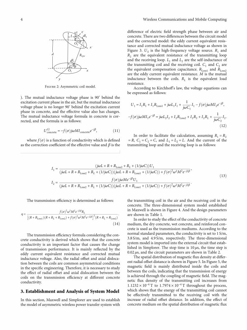
In this section, Maxwell and Simplorer are used to establishthe model of asymmetric wireless power transfer system with
the transmitting coil in the air and the receiving coil in theconcrete. The three-dimensional system model establishedin Maxwell is shown in Figure 4. And the design parametersare shown in Table 1.
In order to study the effect of the conductivity of concretemedium, the dry concrete, wet concrete, and reinforced con-crete is used as the transmission mediums. According to thenormal standard parameters, the conductivity is set to 1 S/m,3.8 S/m, and 4.9 S/m, respectively. The three-dimensionalsystem model is imported into the external circuit that estab-lished in Simplorer. The stop time is 10μs, the time step is0.02μs, and the circuit parameters are shown in Table 2.
The spatial distribution of magnetic flux density at differ-ent radial offset distance is shown in Figure 5. In Figure 5, themagnetic field is mainly distributed inside the coils andbetween the coils, indicating that the transmission of energyis achieved through the coupling of magnetic field. The mag-netic flux density of the transmitting coil increases from1:1232 × 10−4 T to 1:7974 × 10−4 T throughout the process,which shows that the energy of the transmitting coil cannotbe effectively transmitted to the receiving coil with theincrease of radial offset distance. In addition, the effect ofconcrete medium on the spatial distribution of magnetic flux
r1
y
x
z
O1
dl1
𝜑
𝛼
d
t
x´
z´dl2r2
O2
RQN
Figure 2: Asymmetric coil model.
I1 =jωL + R + RLoss2 + RL + 1/jωCð Þð ÞU1
jωL + R + RLoss2 + RL + 1/jωCð Þð Þ jωL + R + RLoss1 + 1/jωCð Þð Þ + f σð Þ2ω2M2e−j2β,
I2 =f σð ÞjωMe−jβU1
jωL + R + RLoss2 + RL + 1/jωCð Þð Þ jωL + R + RLoss1 + 1/jωCð Þð Þ + f σð Þ2ω2M2e−j2β:
ð13Þ
4 Wireless Communications and Mobile Computing
density always exists. The magnetic flux density is obviouslyweakened at the interface between concrete and air. Andthe weakening trend is more obvious with the increase ofradial offset distance, which shows that the transmission ofenergy is hindered by concrete medium to a certain extent.
The simulation current can be obtained at different con-ditions through the Maxwell and Simplorer joint simulationmethod. The current simulation waveform when the radialoffset distance t = 0mm in dry concrete is shown in Figure 6.
The effect of radial offset on the transmission efficiency indifferent concrete medium is shown in Figure 7. The trans-mission efficiency remains almost constant when the radialoffset is in a small scope. With the increase of radial offset dis-tance, the transmission efficiency decreases dramatically. Theeffect of concrete conductivity on the transmission efficiencyis also significant. The transmission efficiency has overallincrease with the continuous decrease of concrete conductiv-ity. Compared with wet and reinforced concrete, the energycan be transmitted in dry concrete at a longer radial offsetdistance. And the trend of transmission efficiency is identicalin different concrete conductivity with the increase of radialoffset distance, which confirms the relationship between theeddy current loss and conductivity in the eddy current lossformula, which further proves that the eddy current loss isan important factor that causes the change of transmissionperformance.
Us
C1 C2
RL
R2R1
L1 L2
M Rloss2Rloss1
Figure 3: Corrected circuit mutual inductance model in concrete.
0 300 600 (mm)
Figure 4: Three-dimensional system model.
Table 1: Design parameters.
Value
Internal diameter 80mm
External diameter 90mm
Wire diameter 2mm
Turns 5 turns
Axial distance 80mm
Concrete size (L ×W ×H) 500 × 250 × 150mm
Table 2: Circuit parameters.
Transmitting loop Receiving loop
Resonant frequency 6MHz
Resistance 0.2Ω
Power supply voltage 18V —
Load — 50Ω
Self-inductance 72.19μH 70.92μH
Matching capacitance 9.74 pF 9.92 pF
5Wireless Communications and Mobile Computing

Concrete
B[tesla]1.1232e−0041.0530e−0049.8282e−0059.1262e−0058.4242e−0057.7222e−0057.0202e−0056.3181e−0055.6161e−0054.9141e−0054.2121e−0053.5101e−0052.8081e−0052.1060e−0051.4040e−0057.0202e−0060.0000e+000
Air
0 150 300 (mm)
(a) t = 0mm
Concrete
Air
B[tesla]1.2899e−0041.2093e−0041.1287e−0041.0481e−004 9.6744e−0058.8682e−0058.0620e−0057.2558e−0056.4496e−0055.6434e−0054.8372e−0054.0310e−0053.2248e−0052.4186e−0051.6124e−0058.0620e−0060.0000e+000
Concrete
Air
0 150 300 (mm)
(b) t = 45mm
Concrete
Air
0 150 300 (mm)
(c) t = 90mm
B[tesla]1.3823e−0041.2959e−0041.2095e−0041.2131e−004 1.0367e−0049.5032e−0058.6393e−0057.7754e−0056.9115e−0056.0475e−0055.1836e−0054.3197e−0053.4557e−0052.5918e−0051.7279e−0058.6396e−0062.7333e−010
Concrete
Air
0 150 300 (mm)
(d) t = 135mm
Figure 5: Continued.
6 Wireless Communications and Mobile Computing

The spatial distribution of magnetic flux density at differ-ent dislocation angle is shown in Figure 8. In Figure 8, themagnetic field is mainly distributed inside the coils andbetween the coils, indicating that the transmission of energyis achieved through the coupling of magnetic field. The mag-netic flux density of the whole system remains almost con-stant with the increase of dislocation angle α from 0° to 45°
indicating that the transmission performance does notchange much. In addition, the magnetic flux density is alsoweakened at the interface between concrete and air. Sincethe magnetic flux density remains almost constant, the weak-ening trend is not obvious with the increase of dislocationangle.
The effect of axial dislocation on the transmission effi-ciency in different concrete medium is shown in Figure 9.When the dislocation angle α varies from 0° to 45°, the trans-mission performance remains steady and the fluctuation of
B[tesla]1.7974e−0041.6851e−0041.5728e−0041.4604e−004 1.3481e−0041.2357e−0041.1234e−0041.0111e−0048.9872e−0057.8638e−0056.7405e−0055.6171e−0054.4937e−0053.3703e−0052.2469e−0051.1236e−0051.7951e−009
Concrete
Air
0 150 300 (mm)
(e) t = 180mm
Figure 5: The spatial distribution of magnetic flux density at different radial offset distance.
0.00 2.00 4.00 6.00 8.00−0.38
−0.25
−0.13
0.00
0.13
0.25
0.38
Curve Info rmsCurrent (Phase_prim)Setup1 : Transient 0.1926
Current (Phase_sec)Setup1 : Transient 0.1829
Time (𝜇s)
Figure 6: Current simulation waveform of the two coils in dry concrete when t= 0mm.
Figure 7: The effect of radial offset on the transmission efficiency indifferent concrete medium (dry concrete σ= 1 S/m, wet concreteσ= 3.8 S/m, and reinforced concrete σ= 4.9 S/m).
7Wireless Communications and Mobile Computing

the transmission efficiency is small. Figure 9 still shows thatthe eddy current loss is an important factor that causes thechange of transmission performance.
Figure 10 shows that the effect of resonant frequency onthe transmission efficiency in different concrete medium.The transmission efficiency drops sharply with the increase
Concrete
Air
0 150 300 (mm)
B[tesla]1.1232e−0041.0530e−0049.8282e−0059.1262e−0058.4242e−0057.7222e−0057.0202e−0056.3181e−0055.6161e−0054.9141e−0054.2121e−0053.5101e−0052.8081e−0052.1060e−0051.4040e−0057.0202e−0060.0000e+000
(a) α = 0°
Concrete
Air
0 150 300 (mm)
B[tesla]9.2676e−0058.6884e−0058.1091e−0057.5299e−005 6.9507e−0056.3715e−0055.7922e−0055.2130e−0054.6388e−0054.0546e−0053.4753e−0052.8961e−0052.3169e−0051.7377e−0051.1584e−0055.7922e−0060.0000e+000
(b) α = 15°
Concrete
Air
0 150 300 (mm)
(c) α = 30°
Concrete
Air
0 150 300 (mm)
(d) α = 45°
Figure 8: The spatial distribution of magnetic flux density at different dislocation angle.
8 Wireless Communications and Mobile Computing

of conductivity at the same resonant frequency which furtherconfirms the correctness of the conclusion analyzed fromFigures 7 and 9. The optimal resonant frequency in dry con-crete is approximately 5.93MHz. The optimal resonant fre-quency in wet concrete is approximately 5.82MHz. And theoptimal resonant frequency in reinforced concrete is approx-imately 5.54MHz. It shows that the optimal resonant fre-quency is gradually decreasing with the increase ofconductivity. Therefore, the frequency shift is also an impor-tant factor that causes the change of transmission perfor-mance. According to the change rule of the transmissionefficiency and the optimal resonant frequency in differentconcrete conductivity, an optimization scheme to improvethe transmission efficiency is proposed. When the transmis-sion efficiency is lower than the normal transmission stan-dard in engineering due to the change of coil position orthe difference of concrete conductivity, the transmission effi-
ciency can be improved by properly reducing the resonantfrequency to close the optimal resonant frequency.Figure 11 shows that the transmission efficiency can beimproved in reinforced concrete by this optimizationscheme. And compared with dry and wet concrete, the trans-mission efficiency has a great improvement in the reinforcedconcrete. Therefore, this optimization scheme is more effec-tive for the system with high conductivity.
4. Experimental Validation
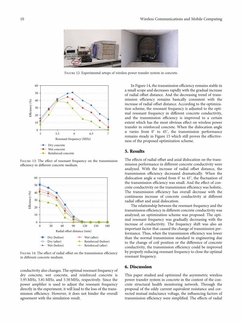
The experimental setups of wireless power transfer systemare shown in Figure 12. The digital signal generator, thepower amplifier, and the DC power supply constitute ahigh-frequency power supply which provides energy formagnetic resonance coupled wireless power transfer system.The impedance matching device ensures the optimal trans-mission performance before the experiments. The transmit-ting coil and the receiving coil are two identical coils, andthe parameters of the coils are given as follows: wire diameter2mm, coil radius 90mm, and 5 turns. To satisfy the experi-mental requirements, the receiving coil and load is sealed inthe concrete. In order to study the effect of the conductivityof concrete medium, the dry concrete, wet concrete, and rein-forced concrete are used as the transmission medium. Theconductivity of the dry concrete, wet concrete, and reinforcedconcrete is measured as 1.31 S/m, 3.63 S/m, and 4.97 S/m.The load is a resistance box of the type EMC5307ALN, andthe resistance value is 50Ω.
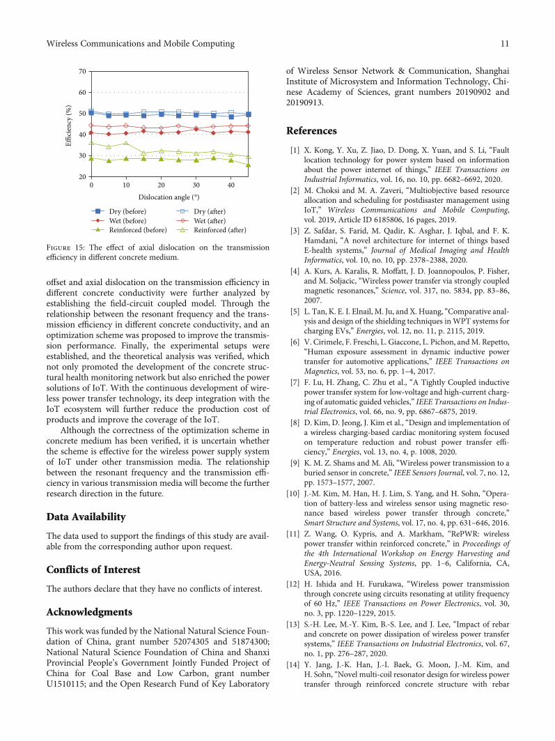
The identical resonant frequency is a precondition formagnetic resonance coupled wireless power transfer, andthe resonant frequency of the system is adjusted to 6MHzby adding the corresponding compensation capacitance.The axial distance between the coils is always fixed at80mm during the experiment. Figure 13 shows that the effectof resonant frequency on the transmission efficiency in dif-ferent concrete medium. The effects of the conductivity ofconcrete medium on the transmission efficiency from big tosmall are reinforced concrete, wet concrete, and dry concrete.And the optimal resonant frequency in different concrete
040
10Dislocation angle (°)
Dry concreteWet concrete
20 30 40
50
60
Figure 9: The effect of axial dislocation on the transmissionefficiency in different concrete medium (dry concrete σ= 1 S/m,wet concrete σ= 3.8 S/m, and reinforced concrete σ= 4.9 S/m).
510
5.5Resonant frequency (MHz)
Dry concreteWet concreteReinforced concrete
Effici
ency
(%)
6 6.5 7
20
30
40
50
60
70
Figure 10: The effect of resonant frequency on the transmissionefficiency in different concrete medium (dry concrete σ= 1 S/m,wet concrete σ= 3.8 S/m, and reinforced concrete σ= 4.9 S/m).
00
22.5Radial offset distance (mm)
Reinforced concrete (before)Reinforced concrete (after)
Effici
ency
(%)
45 67.5 90
10
20
30
40
50
60
Figure 11: The effect of the optimization scheme in reinforcedconcrete (reinforced concrete σ= 4.9 S/m).
9Wireless Communications and Mobile Computing
conductivity also changes. The optimal resonant frequency ofdry concrete, wet concrete, and reinforced concrete is5.95MHz, 5.81MHz, and 5.50MHz, respectively. Since thepower amplifier is used to adjust the resonant frequencydirectly in the experiment, it will lead to the loss of the trans-mission efficiency. However, it does not hinder the overallagreement with the simulation result.
In Figure 14, the transmission efficiency remains stable ina small scope and decreases rapidly with the gradual increaseof radial offset distance. And the decreasing trend of trans-mission efficiency remains basically consistent with theincrease of radial offset distance. According to the optimiza-tion scheme, the resonant frequency is adjusted to the opti-mal resonant frequency in different concrete conductivity,and the transmission efficiency is improved to a certainextent which has the most obvious effect on wireless powertransfer in reinforced concrete. When the dislocation angleα varies from 0° to 45°, the transmission performanceremains steady in Figure 15 which still proves the effective-ness of the proposed optimization scheme.
5. Results
The effects of radial offset and axial dislocation on the trans-mission performance in different concrete conductivity wereanalyzed. With the increase of radial offset distance, thetransmission efficiency decreased dramatically. When thedislocation angle α varied from 0° to 45°, the fluctuation ofthe transmission efficiency was small. And the effect of con-crete conductivity on the transmission efficiency was holistic.The transmission efficiency has overall decrease with thecontinuous increase of concrete conductivity at differentradial offset and axial dislocation.
The relationship between the resonant frequency and thetransmission efficiency in different concrete conductivity wasanalyzed; an optimization scheme was proposed. The opti-mal resonant frequency was gradually decreasing with theincrease of conductivity. The frequency shift was also animportant factor that caused the change of transmission per-formance. Thus, when the transmission efficiency was lowerthan the normal transmission standard in engineering dueto the change of coil position or the difference of concreteconductivity, the transmission efficiency could be improvedby properly reducing resonant frequency to close the optimalresonant frequency.
6. Discussion
This paper studied and optimized the asymmetric wirelesspower transfer system in concrete in the context of the con-crete structural health monitoring network. Through theproposal of the eddy current equivalent resistance and cor-rected mutual inductance voltage, the influencing factors oftransmission efficiency were simplified. The effects of radial
Figure 12: Experimental setups of wireless power transfer system in concrete.
50
5.5Resonant frequency (MHz)
Dry concreteWet concreteReinforced concrete
Effici
ency
(%)
6 6.5 7
10
20
30
40
50
60
Figure 13: The effect of resonant frequency on the transmissionefficiency in different concrete medium.
00
30 60Radial offset distance (mm)
Dry (before)Dry (after)Wet (before)
Effici
ency
(%)
90 120 150 180
10
20
30
40
50
60
Wet (after)Reinforced (before)Reinforced (after)
Figure 14: The effect of radial offset on the transmission efficiencyin different concrete medium.
10 Wireless Communications and Mobile Computing
offset and axial dislocation on the transmission efficiency indifferent concrete conductivity were further analyzed byestablishing the field-circuit coupled model. Through therelationship between the resonant frequency and the trans-mission efficiency in different concrete conductivity, and anoptimization scheme was proposed to improve the transmis-sion performance. Finally, the experimental setups wereestablished, and the theoretical analysis was verified, whichnot only promoted the development of the concrete struc-tural health monitoring network but also enriched the powersolutions of IoT. With the continuous development of wire-less power transfer technology, its deep integration with theIoT ecosystem will further reduce the production cost ofproducts and improve the coverage of the IoT.
Although the correctness of the optimization scheme inconcrete medium has been verified, it is uncertain whetherthe scheme is effective for the wireless power supply systemof IoT under other transmission media. The relationshipbetween the resonant frequency and the transmission effi-ciency in various transmission media will become the furtherresearch direction in the future.
Data Availability
The data used to support the findings of this study are avail-able from the corresponding author upon request.
Conflicts of Interest
The authors declare that they have no conflicts of interest.
Acknowledgments
This work was funded by the National Natural Science Foun-dation of China, grant number 52074305 and 51874300;National Natural Science Foundation of China and ShanxiProvincial People’s Government Jointly Funded Project ofChina for Coal Base and Low Carbon, grant numberU1510115; and the Open Research Fund of Key Laboratory
of Wireless Sensor Network & Communication, ShanghaiInstitute of Microsystem and Information Technology, Chi-nese Academy of Sciences, grant numbers 20190902 and20190913.
References
[1] X. Kong, Y. Xu, Z. Jiao, D. Dong, X. Yuan, and S. Li, “Faultlocation technology for power system based on informationabout the power internet of things,” IEEE Transactions onIndustrial Informatics, vol. 16, no. 10, pp. 6682–6692, 2020.
[2] M. Choksi and M. A. Zaveri, “Multiobjective based resourceallocation and scheduling for postdisaster management usingIoT,” Wireless Communications and Mobile Computing,vol. 2019, Article ID 6185806, 16 pages, 2019.
[3] Z. Safdar, S. Farid, M. Qadir, K. Asghar, J. Iqbal, and F. K.Hamdani, “A novel architecture for internet of things basedE-health systems,” Journal of Medical Imaging and HealthInformatics, vol. 10, no. 10, pp. 2378–2388, 2020.
[4] A. Kurs, A. Karalis, R. Moffatt, J. D. Joannopoulos, P. Fisher,and M. Soljacic, “Wireless power transfer via strongly coupledmagnetic resonances,” Science, vol. 317, no. 5834, pp. 83–86,2007.
[5] L. Tan, K. E. I. Elnail, M. Ju, and X. Huang, “Comparative anal-ysis and design of the shielding techniques inWPT systems forcharging EVs,” Energies, vol. 12, no. 11, p. 2115, 2019.
[6] V. Cirimele, F. Freschi, L. Giaccone, L. Pichon, andM. Repetto,“Human exposure assessment in dynamic inductive powertransfer for automotive applications,” IEEE Transactions onMagnetics, vol. 53, no. 6, pp. 1–4, 2017.
[7] F. Lu, H. Zhang, C. Zhu et al., “A Tightly Coupled inductivepower transfer system for low-voltage and high-current charg-ing of automatic guided vehicles,” IEEE Transactions on Indus-trial Electronics, vol. 66, no. 9, pp. 6867–6875, 2019.
[8] D. Kim, D. Jeong, J. Kim et al., “Design and implementation ofa wireless charging-based cardiac monitoring system focusedon temperature reduction and robust power transfer effi-ciency,” Energies, vol. 13, no. 4, p. 1008, 2020.
[9] K. M. Z. Shams and M. Ali, “Wireless power transmission to aburied sensor in concrete,” IEEE Sensors Journal, vol. 7, no. 12,pp. 1573–1577, 2007.
[10] J.-M. Kim, M. Han, H. J. Lim, S. Yang, and H. Sohn, “Opera-tion of battery-less and wireless sensor using magnetic reso-nance based wireless power transfer through concrete,”Smart Structure and Systems, vol. 17, no. 4, pp. 631–646, 2016.
[11] Z. Wang, O. Kypris, and A. Markham, “RePWR: wirelesspower transfer within reinforced concrete,” in Proceedings ofthe 4th International Workshop on Energy Harvesting andEnergy-Neutral Sensing Systems, pp. 1–6, California, CA,USA, 2016.
[12] H. Ishida and H. Furukawa, “Wireless power transmissionthrough concrete using circuits resonating at utility frequencyof 60 Hz,” IEEE Transactions on Power Electronics, vol. 30,no. 3, pp. 1220–1229, 2015.
[13] S.-H. Lee, M.-Y. Kim, B.-S. Lee, and J. Lee, “Impact of rebarand concrete on power dissipation of wireless power transfersystems,” IEEE Transactions on Industrial Electronics, vol. 67,no. 1, pp. 276–287, 2020.
[14] Y. Jang, J.-K. Han, J.-I. Baek, G. Moon, J.-M. Kim, andH. Sohn, “Novel multi-coil resonator design for wireless powertransfer through reinforced concrete structure with rebar
020
10Dislocation angle (°)
Dry (before)Wet (before)Reinforced (before)
Effici
ency
(%)
20 30 40
30
40
50
60
70
Dry (after)Wet (after)Reinforced (after)
Figure 15: The effect of axial dislocation on the transmissionefficiency in different concrete medium.
11Wireless Communications and Mobile Computing

array,” in 2017 IEEE 3rd International Future Energy Electron-ics Conference and ECCE Asia (IFEEC 2017 - ECCE Asia),,pp. 2238–2243, Kaohsiung, Taiwan, 2017.
[15] X. H. Jin, J. M. Caicedo, and M. Ali, “Near-field wireless powertransfer to embedded smart sensor antennas in concrete,”Applied Computational Electromagnetics Society Journal,vol. 30, no. 3, pp. 261–269, 2015.
[16] R. H. Bhuiyan, R. Islam, J. M. Caicedo, and M. Ali, “A study of13.5-MHz coupled-loop wireless power transfer under con-crete and near metal,” IEEE Sensors Journal, vol. 18, no. 23,pp. 9848–9856, 2018.
[17] J.-M. Kim, M. Han, and H. Sohn, “Magnetic resonance-basedwireless power transmission through concrete structures,”Journal of Electromagnetic Engineering and Science, vol. 15,no. 2, pp. 104–110, 2015.
[18] O. Jonah and S. V. Georgakopoulos, “Wireless power transferin concrete via strongly coupled magnetic resonance,” IEEETransactions on Antennas and Propagation, vol. 61, no. 3,pp. 1378–1384, 2013.
[19] S. R. Khan, S. K. Pavuluri, and M. P. Y. Desmulliez, “Accuratemodeling of coil inductance for near-field wireless powertransfer,” IEEE Transactions on Microwave Theory and Tech-niques, vol. 66, no. 9, pp. 4158–4169, 2018.
[20] B. K. Kushwaha, G. Rituraj, P. Kumar, and P. Bauer, “Mathe-matical model for the analysis of series-parallel compensatedwireless power transfer system for different misalignments,”IET Circuits, Devices & Systems, vol. 13, no. 7, pp. 970–978,2019.
[21] F. Liu, Y. Yang, D. Jiang, X. Ruan, and X. Chen, “Modeling andoptimization of magnetically coupled resonant wireless powertransfer system with varying spatial scales,” IEEE Transactionson Power Electronics, vol. 32, no. 4, pp. 3240–3250, 2017.
[22] P. Gao, Z. Tian, T. Pan, J. Wu, andW. Gui, “Transmission effi-ciency analysis and optimization of magnetically coupled res-onant wireless power transfer system with misalignments,”AIP Advances, vol. 8, no. 8, 2018.
[23] Z. Zhang and B. Zhang, “Angular-misalignment insensitiveomnidirectional wireless power transfer,” IEEE Transactionson Industrial Electronics, vol. 67, no. 4, pp. 2755–2764, 2020.
[24] D. Liu and S. V. Georgakopoulos, “Cylindrical misalignmentinsensitive wireless power transfer systems,” IEEE Transac-tions on Power Electronics, vol. 33, no. 11, pp. 9331–9343,2018.
[25] L. Murliky, R. W. Porto, V. J. Brusamarello, F. R. de Sousa, andA. Triviño-Cabrera, “Active tuning of wireless power transfersystem for compensating coil misalignment and variable loadconditions,” AEU - International Journal of Electronics andCommunications, vol. 119, article 153166, 2020.
12 Wireless Communications and Mobile Computing