Analysis and design of cold-formed C-section members and...
38
Analysis and design of cold-formed C-section members and structures PhD Theses Open Discussion 5 February 2010 Candidate: Jakab Gábor Supervisor: Dr. Dunai László
Transcript of Analysis and design of cold-formed C-section members and...

Analysis and design of cold-formed C-section members and structures
PhD Theses Open Discussion5 February 2010
Candidate: Jakab GáborSupervisor: Dr. Dunai László

Introduction• Basic research and industrial R&D• Subject
– compression C-section members– truss system made of C-section members– numerical modelling
PhD Theses Open Discussion 5 February 2010

Introduction• General aims
– stability behaviour– failure mode identification– load-bearing capacity– design method development
• Methodology– laboratory tests– standard-based calculations– numerical model development
PhD Theses Open Discussion 5 February 2010

C-section members
• Effect of load introduction• Members with single and double sections• 10 different arrangements• C150/1.0 – C200/2.5
– web b/t: 80-200
• Specimen lengths– 800, 1500, 2000, 2500, 3600 mm
• 37 + 61 tests (2002, 2008)
PhD Theses Open Discussion 5 February 2010

C-section members - specimens
• Single members with different eccentricities• Doubled members – stuck into each-other
– Two C-sections– C-section + U-section
• Doubled members – back-to-back arrangement• Doubled members – back-to-back arrangement• Single member laterally supported by hat sections
PhD Theses Open Discussion 5 February 2010

C-section members - tests
CompressionC SimpleC C
PhD Theses Open Discussion 5 February 2010

C-section members - tests
Brace IC Brace IC Column
PhD Theses Open Discussion 5 February 2010

C-section members - tests
CC DoubleC CU
PhD Theses Open Discussion 5 February 2010

C-section members - tests
PhD Theses Open Discussion 5 February 2010

• Failure mode identification• Test-based design resistances
– one test leads to conservative result: Radj/Rd ~ 1.5– tendencies of double arrangements– „family of tests”: effect of eccentricity
C-section members - evaluation
– „family of tests”: effect of eccentricity
• Design codes– ENV EC3-1-3:1996 (pre-standard)– MSZ EN EC3-1-3:2006 (operational standard)
PhD Theses Open Discussion 5 February 2010
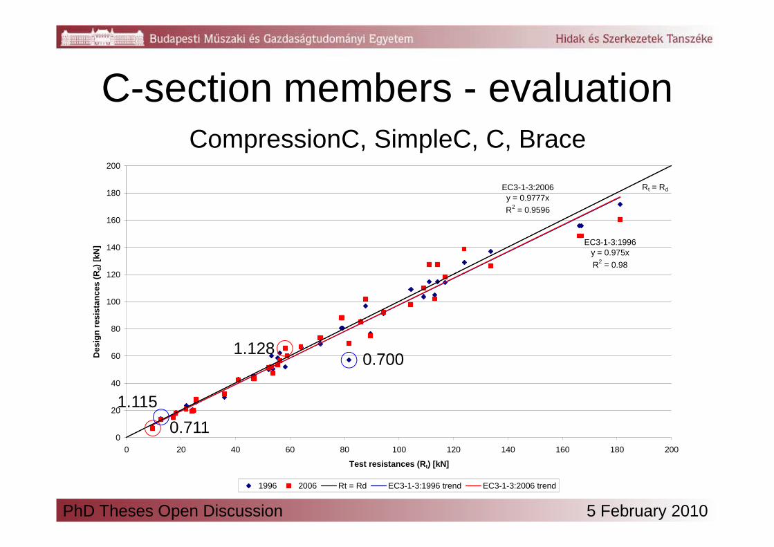
EC3-1-3:1996y = 0.975x
R2 = 0.98
EC3-1-3:2006y = 0.9777x
R2 = 0.9596
Rt = Rd
120
140
160
180
200
Des
ign
res
ista
nce
s (R
d)
[kN
]C-section members - evaluation
CompressionC, SimpleC, C, Brace
0
20
40
60
80
100
120
0 20 40 60 80 100 120 140 160 180 200
Test resistances (Rt) [kN]
Des
ign
res
ista
nce
s (R
1996 2006 Rt = Rd EC3-1-3:1996 trend EC3-1-3:2006 trend
0.700
0.711
1.115
1.128
PhD Theses Open Discussion 5 February 2010

8.08.0 ∆+ MMN
C-section members - design
1/
)(
/ 0,,
,,
0min
≤⋅
∆+⋅+
⋅⋅ Mcomzeffyb
EdzEdzz
Meffyb
Ed
Wf
MM
Af
N
γκ
γχ
EC3: interaction of flexural buckling and bending
nomEdEdz eNM ⋅=,EC3-1-3:1996
1,,
≤
∆++
Rdb
EdEd
Rdb
Ed
M
MM
N
N
( ) ( ) 165.065.0
,,≤+ ∆+
Rdb
EdEd
Rdb
Ed
MMM
NN
nomee ⋅= 4.1mod
Sye ⋅≥ 4.0mod
EC3-1-3:2006
PhD Theses Open Discussion 5 February 2010

y = 0.8919x
R2 = 0.9801
y = 0.8168x
R2 = 0.9614
Rt = Rd
120
140
160
180
200
Des
ign
res
ista
nce
s (R
d)
[kN
]C-section members - design
0
20
40
60
80
100
0 20 40 60 80 100 120 140 160 180 200
Test resistances (Rt) [kN]
Des
ign
res
ista
nce
s (R
EC3-1-3:1996, modified EC3-1-3:2006, modified Rt = Rd EC3-1-3:1996, mod., trend EC3-1-3:2006, mod., trend
PhD Theses Open Discussion 5 February 2010

• C-section laterally supported by hat sections
0.1/5.0 1
≤⋅⋅ Meffyb
Ed
Af
N
γ
• Doubled members
C-section members - design
• Doubled members
αγ
κγχ
≤⋅
∆+⋅+
⋅⋅ 1,,
,,
1min /
)(
/ Mcomzeffyb
EdzEdzz
Meffyb
Ed
Wf
MM
Af
N
Arrangement
IC Column 0.8·L+1.0, L length of member [m]
CC 1.8
CU1.3, if C-section is loaded1.8, if U-section loaded
IC Brace 2.5
α
PhD Theses Open Discussion 5 February 2010

• single C-section members with load introduction in the web or in the web and the flanges using self-drilling screws, and load introduction in the flanges using bolts,
• single C-section members with load introduction in the web using self-drilling
I worked out and completed an experimental test program on compression members made of cold-formed C-sections with cross-sectional configurations and supporting conditions, which were not analysed previously.I determined and classified the stability behaviour of
Thesis 1
• single C-section members with load introduction in the web using self-drilling screws, laterally supported by hat sections in discrete points at one flange,
• members made of two C-sections in a back-to-back arrangement connected to each-other at the webs by self-drilling screws, with load introduction in the web or in the flanges using bolts,
• members made by sticking two C-sections in each-other, connected at the flanges by self-drilling screws, with load introduction in the webs or in the web and the flanges using self-drilling screws,
• members made by sticking a C- and a U-section in each-other, connected at the flanges by self-drilling screws, with load introduction in web of the C-section and the flanges using self-drilling screws.
PhD Theses Open Discussion 5 February 2010

Thesis 2
I developed Eurocode-based design methods for the members studied in the laboratory tests based on the comparative analysis of the test-based design resistances and behaviour modes.
• I defined the eccentricity to be taken into account in the design of single C-section members without lateral support,
• I defined the interaction formula of single C-section members without • I defined the interaction formula of single C-section members without lateral support in compression and bending about the weak axis,
• I developed a design method for single C-section members laterally supported at one flange,
• I derived the design resistances of members with complex cross-sectional arrangement on the basis of the design resistance of single members.
PhD Theses Open Discussion 5 February 2010

• System development from scratch– Spanning 12..24 m– Minimum eave height, distance of trusses– Only C-section members, simple arrangement and
Truss system
– Only C-section members, simple arrangement and detailing
• Tasks– Structural arrangement– Standard-based design method– Design method validation
PhD Theses Open Discussion 5 February 2010

Truss system – test setup
PhD Theses Open Discussion 5 February 2010

Truss system – Test 1
failure in the upper chord – interaction of flexural buckling and bending
PhD Theses Open Discussion 5 February 2010

Truss system – Test 3
• failure in the upper chord – global buckling of a built-up member

Truss system – Test 4
• failure in compression brace members –interaction of compression and bending
PhD Theses Open Discussion 5 February 2010

Truss system – Test 5
• failure if the lower chord joints next to the support – interaction of shear buckling and tension
PhD Theses Open Discussion 5 February 2010

Truss system – Test 5
failure in the upper chord – interaction of flexural buckling and bending
PhD Theses Open Discussion 5 February 2010

Truss system – design
• Design resistance of a chord member– reduced out-of-plane eccentricity
• Global analysis– 2D beam FE model verified based tests results
1/
)5.0(
/
)(
/ 1,,
,,
1,,
,,
1min
≤⋅
∆+⋅⋅+
⋅⋅∆+⋅
+⋅⋅ Mcomzeffyb
EdzEdzz
McomyeffybLT
EdyEdyLT
Meffyb
Ed
Wf
MM
Wf
MM
Af
N
γκ
γχκ
γχ
• Design resistance of brace member– additional in-plane eccentricity
1// 0,,
,,
0
≤⋅
∆++⋅+
⋅ Mycomzeff
EdzEdzaddEd
Mybeff
Ed
bfW
MMeN
fA
N
γγ eadd = max(8 mm, 0.2·b1)
PhD Theses Open Discussion 5 February 2010

• Design resistance of joints– shear buckling failure
Truss system – design
5
,,
3 M
effvywRdb
AfV
γχ
⋅⋅⋅
=wχ with 34.5=τk
with if compression chord member, otherwise A = AA
4=σk
– joint – chord member interaction
53 Mγ⋅
( ) ( ) 52
,,,,0,0 //1 MRdbEdyeffvyeffveffRd VVfAfAAN γ
−⋅⋅+⋅−=
with if compression chord member, otherwise Av,eff = Av,g
effvA ,4=σk
effA ,0
Aeff, if compression chord member, otherwise Ag
PhD Theses Open Discussion 5 February 2010

I completed an experimental test program on prototypes of a truss system made of cold-formed C-sections. The specialities of the structural arrangement are: i) the chord members consist of two C-sections in a back-to-back arrangement, with a distance equal to the web height of the brace members, ii) brace members are stuck between the chord members, iii) structural joints are made using fitted bolts, iv) brace members may be of single sections or doubled in a back-to-back arrangement. I determined and characterized the behaviour of the truss based on the following
Thesis 3
I determined and characterized the behaviour of the truss based on the following observed failure modes:
• interacting out-of-plane global and local buckling of compression chord members,
• interacting out-of-plane global and local buckling of built-up compression chord members,
• cross-section failure of compression brace members at the element end,• cross-section failure of brace-to-chord and chord-to-chord structural joints.
Based on the observed behaviour I defined constructional rules regarding the detailing of the joints ensuring favourable structural behaviour.
PhD Theses Open Discussion 5 February 2010

Thesis 4I developed Eurocode-based design method for the structural members of the trusses studied in the laboratory tests based on the observed behaviour andfailure modes and validated them based on the measured load-bearing capacities.
• I defined the modelling level to be applied in global analysis and verified the model based on the results of strain and deflection measurements,
• I defined the magnitude of eccentricity to be taken into account in the design of compression chord and brace members,compression chord and brace members,
• I developed a design method to calculate the design resistance of structural joints, taking into account the interaction of structural members and joints.
PhD Theses Open Discussion 5 February 2010

Numerical model• Aim: virtual experimenting
– C-section compression member (SimpleC)– Truss (Test 1, 5)
• Modelling level: GMNIA– surface model– surface model– material model based on tensile tests– equivalent geometrical imperfections
• General approach– „Exact” geometrical modelling– Elements used– Contact surfaces
PhD Theses Open Discussion 5 February 2010
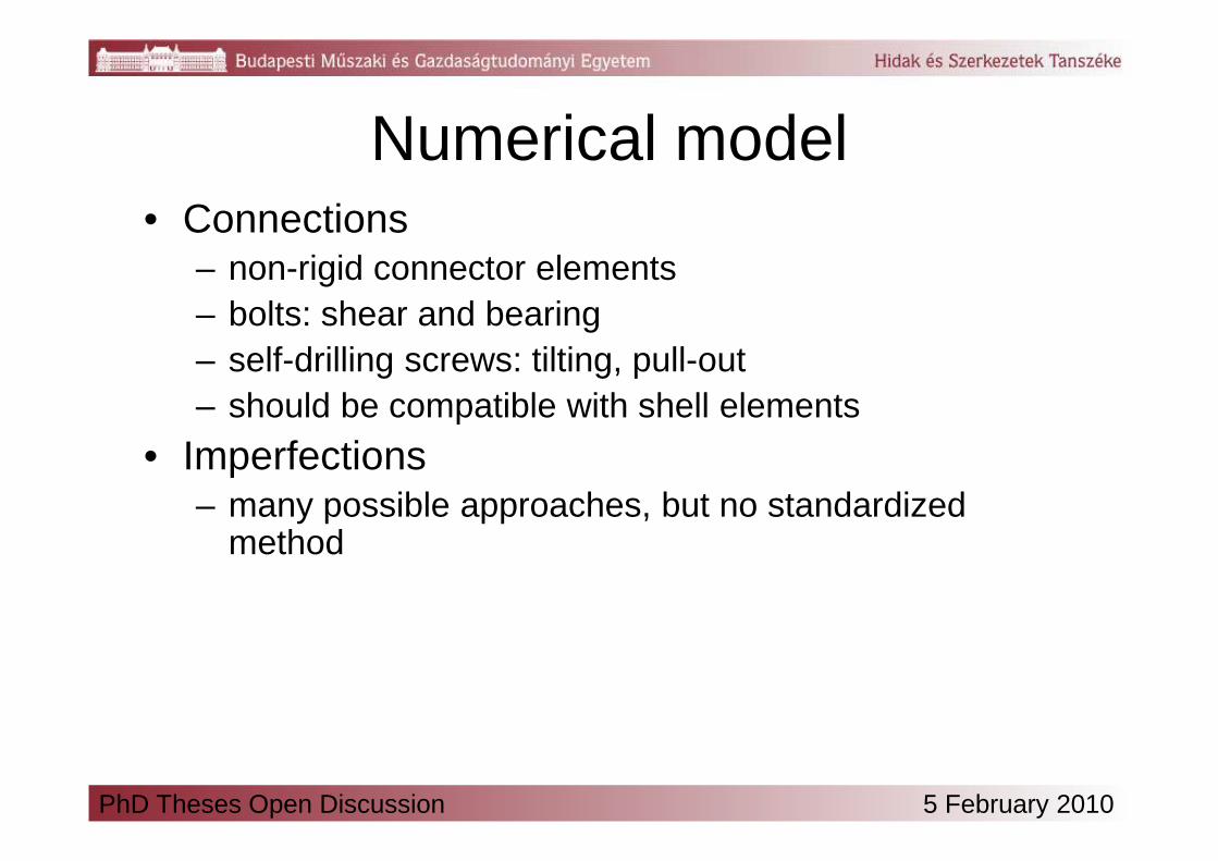
Numerical model• Connections
– non-rigid connector elements– bolts: shear and bearing– self-drilling screws: tilting, pull-out– should be compatible with shell elements
• Imperfections– many possible approaches, but no standardized
method
PhD Theses Open Discussion 5 February 2010

• Self-drilling screws– „beamstar”– calibrated by 2 parameters
Numerical model - SimpleC
PhD Theses Open Discussion 5 February 2010
area[mm2]
Shear divider
Second moment of
inertia [mm4]
Torsional moment of
inertia [mm4]
Shaft r2π 70 r4π/4 r4π/4
Radial element
100 0 0.01 1

Numerical model - SimpleC
• Imperfections– shapes and wavelengths
obtained from cFSM analysis– weight of modes is known– imperfection sensitivity – imperfection sensitivity
analysis is possible
shape local global
amplitude [mm] 3 -6
half-wavelength 150 mm member length
PhD Theses Open Discussion 5 February 2010
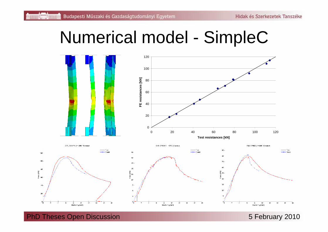
Numerical model - SimpleC
20
40
60
80
100
120
FE
res
ista
nce
s [k
N]
0
20
0 20 40 60 80 100 120
Test resistances [kN]
PhD Theses Open Discussion 5 February 2010

Numerical model – truss
• Bolts– modified „beamstar”– calibrated by 1 parameter
PhD Theses Open Discussion 5 February 2010
element type
area[mm2]
shear divider
Iz [mm4] Iy [mm4] Ix [mm4]
Test 1Test 5
BEAM4 r2π 0 r4π/4 r4π/4 r4π/4
BEAM44 10-3 0 100 0.1 0
Test 1 LINK10 0.4 - - - -
Test 5 LINK10 1.0 - - - -

Numerical model – truss
applied imperfections
shape Nr. amplitude [mm]
3 7.5
15 1.5
PhD Theses Open Discussion 5 February 2010

Numerical model – truss
PhD Theses Open Discussion 5 February 2010

I developed shell finite element models of the single C-section members with load introduction in the web using self-drilling screws and of the truss girders, both capable of carrying out virtual experiments by materially and geometrically nonlinear analysis. The specialities of the models are the modelling of equivalent geometrical imperfections and modelling connector elements. I generated the imperfections of the models as follows:
Thesis 5
• in the case of the single C-section members using the constrained finite strip method enabling the control of the weight of pure – local, distortional, global –buckling modes in the generated imperfect shape,
• in the case of the truss girders based on selected eigenshapes of the model.
I developed models of connector elements used in the laboratory tests, compatible with shell elements and capable of following the structural behaviour as: tilting and pull-out in the case of self-drilling screws, shear and bearing in the case of bolts.I used the laboratory test results to determine the stiffness parameters of the models of the connector elements, and the shape and amplitude of imperfections to be applied on the model.
PhD Theses Open Discussion 5 February 2010

Acknowledgementto László Dunai for showing the way, for the encouragement, for the opportunity and for the friendship,
to Nau, Dani, Attila, Levi, Geri and István for the ideas and insights,
to the laboratory staff, especially Miklós Kálló for their help during the tests,
to all my colleagues at the department for the teaching,
to my family and to Zsófi for their support and love.
PhD Theses Open Discussion 5 February 2010

Thank you for your attention!
PhD Theses Open Discussion 5 February 2010