ANALYSING THE CAUSES OF BLACKENING OF … Blackening of ends of fluorescent lamps 10 7.2 Lamp Start...
10
COSINE DEVELOPMENTS “LEADERS IN LIGHTING TECHNOLOGY” Doc No. 020-100-741 Rev 1 Page 1 of 10 A A N N A A L L Y Y S S I I N N G G T T H H E E C C A A U U S S E E S S O O F F B B L L A A C C K K E E N N I I N N G G O O F F E E N N D D S S O O F F F F L L U U O O R R E E S S C C E E N N T T L L A A M M P P S S Date of original issue : February 2008
Transcript of ANALYSING THE CAUSES OF BLACKENING OF … Blackening of ends of fluorescent lamps 10 7.2 Lamp Start...

COSINE DEVELOPMENTS “LEADERS IN LIGHTING TECHNOLOGY”
Doc No. 020-100-741 Rev 1 Page 1 of 10
AANNAALLYYSSIINNGG TTHHEE CCAAUUSSEESS
OOFF
BBLLAACCKKEENNIINNGG OOFF EENNDDSS
OOFF
FFLLUUOORREESSCCEENNTT LLAAMMPPSS
Date of original issue : February 2008

COSINE DEVELOPMENTS “LEADERS IN LIGHTING TECHNOLOGY”
Doc No. 020-100-741 Rev 1 Page 2 of 10
INDEX
1 SCOPE 3 2 INTRODUCTION 3 3 FLUORESCENT LAMP CONSTRUCTION 3 4 PRINCIPLES OF OPERATION 4
4.1 Efficiency 6 5 STARTING THE LAMP 6
5.1 Hot cathode versus Cold Cathode 6 5.1.1 Hot Cathode 7 5.1.2 Cold Cathode 7
5.2 Ballasts 7 5.2.1 Electronic Ballasts 7 5.2.2 Emergency Ballasts 7
6 END OF LIFE 8
6.1 Emission Mix 8 6.2 Ballast Electronics 9 6.3 Phosphor 9 6.4 Loss of Mercury 9
7 CONCLUSIONS 10 7.1 Blackening of ends of fluorescent lamps 10
7.2 Lamp Start 10

COSINE DEVELOPMENTS “LEADERS IN LIGHTING TECHNOLOGY”
Doc No. 020-100-741 Rev 1 Page 3 of 10
1. Scope The scope of the document is to highlight and describe the causes of Blackening at Ends of Fluorescent lamps.
2. Introduction
To understand fluorescent lamps, it helps to know a little about light itself. Light is a form of energy that can be released by an atom. It is made up of many small particle-like packets that have energy and momentum but no mass. These particles, called light photons, are the most basic units of light. Further to this a basic understanding of the construction and principles of operation of fluorescent lamps will help. This is explained further in the document.
3. Fluorescent Lamp Construction
The fluorescent lamp is a form of low pressure mercury discharge lamp. It usually takes the form of a long glass tube coated on its inner surface with a fluorescent powder or phosphor. At each end of the tube is a lamp cathode. The cathode consists of a coiled tungsten heater coated with special oxides of Barium and Strontium which readily emit electrons when heated. Attached to each cathode are two protective plates which prevent the destruction of the heater coil by the bombardment of positive ions during the discharge. The glass tube is sealed at both ends and contains a small amount of mercury and an inert gas at low pressure. The gas can be argon, krypton or a mixture thereof.
Fig 1 – Basic configuration of a Fluorescent lamp The central element in a fluorescent lamp is a sealed glass tube. As depicted in Fig 1 the tube contains a small bit of mercury and an inert gas, typically argon, kept under very low pressure. The tube also contains a phosphor powder, coated along the inside of the glass.
COSINE DEVELOPMENTS “LEADERS IN LIGHTING TECHNOLOGY”
Doc No. 020-100-741 Rev 1 Page 4 of 10
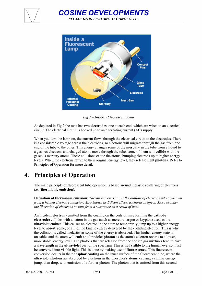
Fig 2 – Inside a Fluorescent lamp As depicted in Fig 2 the tube has two electrodes, one at each end, which are wired to an electrical circuit. The electrical circuit is hooked up to an alternating current (AC) supply.
When you turn the lamp on, the current flows through the electrical circuit to the electrodes. There is a considerable voltage across the electrodes, so electrons will migrate through the gas from one end of the tube to the other. This energy changes some of the mercury in the tube from a liquid to a gas. As electrons and charged atoms move through the tube, some of them will collide with the gaseous mercury atoms. These collisions excite the atoms, bumping electrons up to higher energy levels. When the electrons return to their original energy level, they release light photons. Refer to Principles of Operation for more detail.
4. Principles of Operation
The main principle of fluorescent tube operation is based around inelastic scattering of electrons i.e. (thermionic emission).
Definition of thermionic emission: Thermionic emission is the outflow of electrons into a vacuum from a heated electric conductor. Also known as Edison effect; Richardson effect. More broadly, the liberation of electrons or ions from a substance as a result of heat. An incident electron (emitted from the coating on the coils of wire forming the cathode electrode) collides with an atom in the gas (such as mercury, argon or krypton) used as the ultraviolet emitter. This causes an electron in the atom to temporarily jump up to a higher energy level to absorb some, or all, of the kinetic energy delivered by the colliding electron. This is why the collision is called 'inelastic' as some of the energy is absorbed. This higher energy state is unstable, and the atom will emit an ultraviolet photon as the atom's electron reverts to a lower, more stable, energy level. The photons that are released from the chosen gas mixtures tend to have a wavelength in the ultraviolet part of the spectrum. This is not visible to the human eye, so must be converted into visible light. This is done by making use of fluorescence. This fluorescent conversion occurs in the phosphor coating on the inner surface of the fluorescent tube, where the ultraviolet photons are absorbed by electrons in the phosphor's atoms, causing a similar energy jump, then drop, with emission of a further photon. The photon that is emitted from this second
COSINE DEVELOPMENTS “LEADERS IN LIGHTING TECHNOLOGY”
Doc No. 020-100-741 Rev 1 Page 5 of 10
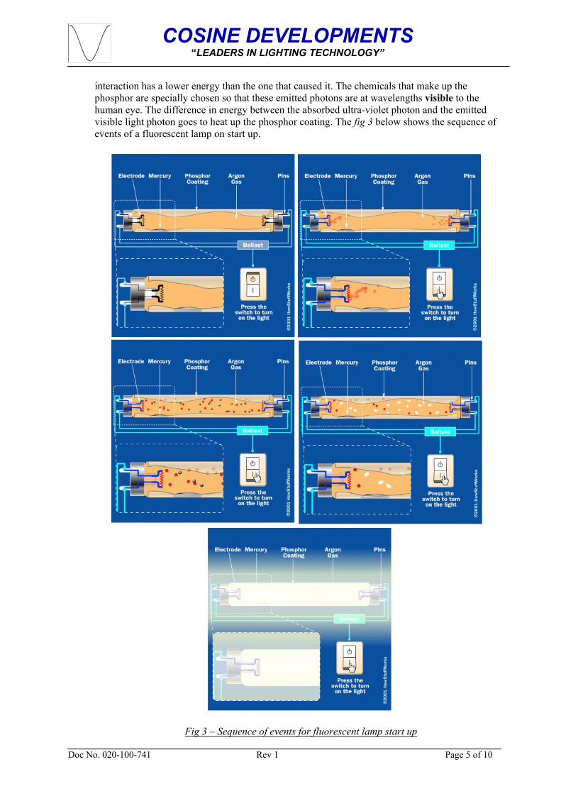
interaction has a lower energy than the one that caused it. The chemicals that make up the phosphor are specially chosen so that these emitted photons are at wavelengths visible to the human eye. The difference in energy between the absorbed ultra-violet photon and the emitted visible light photon goes to heat up the phosphor coating. The fig 3 below shows the sequence of events of a fluorescent lamp on start up.
Fig 3 – Sequence of events for fluorescent lamp start up

COSINE DEVELOPMENTS “LEADERS IN LIGHTING TECHNOLOGY”
Doc No. 020-100-741 Rev 1 Page 6 of 10
NOTE! It should be noted that during each starting cycle, a quantity of the emissive material is lost from each cathode. This material tends to pollute the lamp gas and phosphor coatings and is noticeable in older lamps as a dark band around each cathode. This pollution leads to a progressive reduction in the output of the lamp (lumen depreciation). When there is no longer enough electron emissive material to provide the correct volume of free electrons during startup, the lamps will no longer strike. A break in a lamp cathode will also under normal circumstances prevent a lamp from striking. 4.1 Efficiency
The efficiency of fluorescent tubes ranges from about 16 lumens/watt for a 4 watt tube with an ordinary ballast to as high as about 95 lumens/watt for a 32 watt tube with modern electronic ballast, commonly averaging 50 to 67 lm/W overall. Most compact fluorescents 13 watts or more with integral electronic ballasts achieve about 60 lumens/watt. Due to phosphor degradation as they age, the average brightness over the entire service life is actually about 10% less.
5. Starting The lamp
The mercury atoms in the fluorescent tube must be ionized before the arc can "strike" within the tube. For small lamps, it does not take much voltage to strike the arc and starting the lamp presents no problem, but larger tubes require a substantial voltage (in the range of a thousand volts). In some cases, that is exactly how it is done: instant start fluorescent tubes simply use a high enough voltage to break down the gas and mercury column and thereby start arc conduction. In other cases, a separate starting aid must be provided. Some fluorescent designs (preheat lamps) use a combination filament/cathode at each end of the lamp in conjunction with a mechanical or automatic switch that initially connect the filaments in series with the ballast and thereby preheats the filaments prior to striking the arc.
Today, the most popular fluorescent lamp design is the rapid start lamp. This design works on the same basic principle as the traditional starter lamp, but it doesn't have a starter switch. Instead, the lamp's ballast constantly channels current through both electrodes. This current flow is configured so that there is a charge difference between the two electrodes, establishing a voltage across the tube.
When the fluorescent light is turned on, both electrode filaments heat up very quickly (Hot Cathode), boiling off electrons, which ionize the gas in the tube. Once the gas is ionized, the voltage difference between the electrodes establishes an electrical arc. The flowing charged particles (red) excite the mercury atoms (silver), triggering the illumination process.
5.1 Hot Cathode versus Cold Cathode Operation
The cathode is the negative electrode of the fluorescent lamp. Current flows by way of electrons emitted from the cathode and attracted to the positive electrode, the anode. A hot cathode is one which must be heated to operate properly - to emit sufficient electrons to be useful. Examples: TV and monitor CRTs, most vacuum tubes (or valves), vacuum fluorescent displays (like those on your VCR). This is as explained in paragraph 4 is “thermionic emission” - the boiling off of electrons from the surface of the cathode. Normal fluorescent lamps are hot cathode devices - partially maintained by the discharge current itself. They all have some sort of warm-up period (though it can be quite short).

COSINE DEVELOPMENTS “LEADERS IN LIGHTING TECHNOLOGY”
Doc No. 020-100-741 Rev 1 Page 7 of 10
5.1.1 Hot Cathode
Thermal emission is the primary process used in "hot cathode" lamps which include standard fluorescent tubes. The ions are accelerated towards the cathode through a small cathode voltage (less than 10 volts) and gain just enough energy to heat a small part of the very fine wire electrode when they collide with it. They heat it until it glows dully and electrons are "boiled off", liberated by the thermal energy. This process is very efficient in producing lots of electrons and results in efficient lamps.
5.1.2 Cold Cathode
Secondary emission is a more brutal process for generating electrons. It requires an accelerating voltage drop of 130 to 150 volts. The energetic ions simply "knock" electrons off the metal surface. In so doing they also knock some of the metal off as well, a process called sputtering. The big electrodes T12 and T8 have enough material to last before other effects cause lamp failure. T5 lamp filaments are much more flimsy and are subject to being damaged much easier.
5.2 Ballasts
5.2.1 Electronic Ballasts
Newer rapid start ballast designs provide filament power windings within the ballast; these rapidly and continuously warm the filaments/cathodes using low-voltage AC. No inductive voltage spike is produced for starting, so the lamps must usually be mounted near a grounded (earthed) reflector to allow the glow discharge to propagate through the tube and initiate the arc discharge.
Electronic ballasts often revert to a style in-between the preheat and rapid-start styles: a capacitor (or sometimes an autodisconnecting circuit) may complete the circuit between the two filaments, providing filament preheating. When the tube lights, the voltage and frequency across the tube and capacitor typically both drop, thus capacitor current falls to a low but non-zero value. Generally this capacitor and the inductor, which provides current limiting in normal operation, form a resonant circuit, increasing the voltage across the lamp so it can easily start.
Some electronic ballasts use programmed start. The output AC frequency is started above the resonance frequency of the output circuit of the ballast; and after the filaments are heated, the frequency is rapidly decreased. If the frequency approaches the resonant frequency of the ballast, the output voltage will increase so much that the lamp will ignite. If the lamp does not ignite, an electronic circuit stops the operation of the ballast.
5.2.1 Emergency Control Ballasts
Emergency Control Ballasts are designed to operate a fluorescent lamp when an outage of mains occurs. This is generally not an everyday occurrence. As a result the designer of Emergency Control ballasts does not take into consideration the niceties of striking a fluorescent lamp to prevent any filament damage etc. Cost is also a consideration. As a result most Emergency Control Ballasts operate the lamp on a cold-strike and as explained in para 5.1.2 causing the “knocking” off
COSINE DEVELOPMENTS “LEADERS IN LIGHTING TECHNOLOGY”
Doc No. 020-100-741 Rev 1 Page 8 of 10
of electrons which includes the knocking of material off the filaments. Secondly most emergency lamps are operated at a much lower illuminance level of ±20% of normal further causing the depletion of the electrode causing blackening of ends.
6. End of life
The end of life failure mode for fluorescent lamps varies depending how they are used and their control gear type. There are three (3) main failure modes currently, and a fourth which is starting to appear:
6.1 Emission Mix
Underlying all tube operation is the fact that any metal is continuously emitting electrons. Both the number and the speed with which they are emitted increases very strongly with temperature, although in fact emission takes place at anything above absolute zero (-273°C). To understand emission, we have to look at what is going on inside the body of the metal. In any metal, there are one or two electrons that can easily be detached from an atom, so that inside the solid metal there is a kind of sea of electrons floating around independently of any particular atom. The latter are fixed in place inside the crystal structure and do not move about at all, although they vibrate in place. This sea of electrons is common to all metals, and indeed is really the defining characteristic of a metal and explains many of their familiar properties such as electrical conductivity and the fact that they are shiny. Since the electrons are not attached to any particular atom, they move about constantly, very much like the molecules in a gas. The average speed of the electrons increases with temperature, but because they are constantly bouncing off of the atoms and each other they do not all have the same speed but rather obey a statistical distribution law.
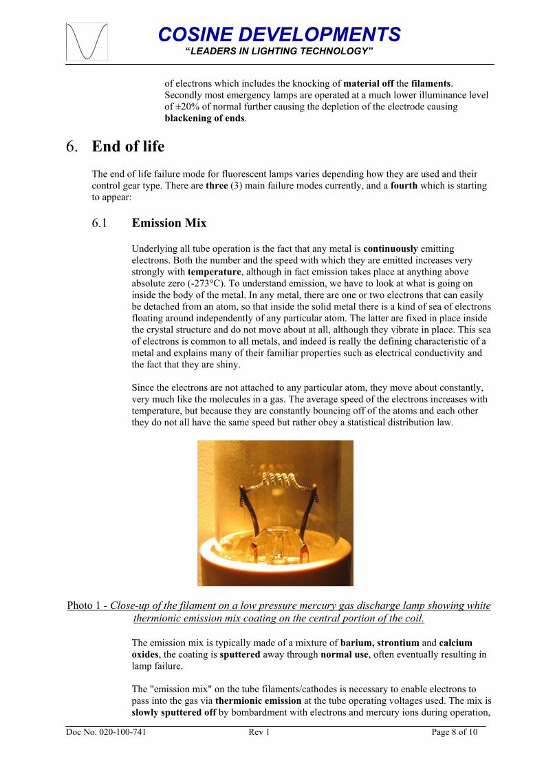
Photo 1 - Close-up of the filament on a low pressure mercury gas discharge lamp showing white thermionic emission mix coating on the central portion of the coil.
The emission mix is typically made of a mixture of barium, strontium and calcium oxides, the coating is sputtered away through normal use, often eventually resulting in lamp failure. The "emission mix" on the tube filaments/cathodes is necessary to enable electrons to pass into the gas via thermionic emission at the tube operating voltages used. The mix is slowly sputtered off by bombardment with electrons and mercury ions during operation,
COSINE DEVELOPMENTS “LEADERS IN LIGHTING TECHNOLOGY”
Doc No. 020-100-741 Rev 1 Page 9 of 10
but a larger amount is sputtered off each time the tube is started with cold cathodes. Lamps operated for typically less than 3 hours each switch-on will normally run out of the emission mix before other parts of the lamp fail. The sputtered emission mix forms the dark marks at the tube ends seen in old tubes. When all the emission mix is gone, the cathode cannot pass sufficient electrons into the gas fill to maintain the discharge at the designed tube operating voltage. Ideally, the control gear should shut down the tube when this happens. However, some control gear will provide sufficient increased voltage to continue operating the tube in cold cathode mode, which will cause overheating of the tube end and rapid disintegration of the electrodes and their support wires until they are completely gone or the glass cracks, wrecking the low pressure gas fill and stopping the gas discharge.
6.2 Ballast electronics
This is only relevant to compact fluorescent lamps with integral electrical ballasts. Ballast electronics failure is a somewhat random process which follows the standard failure profile for any electronic devices. Integral electronic ballasts suffer from shortened lifespans in high humidity applications. There is an initial small peak of early failures, followed by a drop and steady increase over lamp life. Life of electronics is heavily dependent on operating temperature—it typically halves for each 10 °C temperature rise. The quoted average life of a lamp is usually at 25 °C ambient (this may vary by country). The average life of the electronics at this temperature is normally greater than this, so at this temperature, not many lamps will fail due to failure of the electronics. In some fittings, the ambient temperature could be well above this, in which case failure of the electronics may become the predominant failure mechanism. Similarly, running a compact fluorescent lamp base-up will result in hotter electronics and shorter average life (particularly with higher power rated ones). Electronic ballasts should be designed to shut down the tube when the emission mix runs out as described above. In the case of integral electronic ballasts, since they never have to work again, this is sometimes done by having them deliberately burn out some component to permanently cease operation.
6.3 Phosphor
The phosphor drops off in efficiency during use. By around 25,000 operating hours, it will typically be half the brightness of a new lamp (although some manufacturers claim much longer half-lives for their lamps). Lamps which do not suffer failures of the emission mix or integral ballast electronics will eventually develop this failure mode. They still work, but have become dim and inefficient. The process is slow, and often only becomes obvious when a new lamp is operating next to an old lamp.
6.4 Loss of mercury
Mercury is lost from the gas fill throughout the lamp life, as it is slowly absorbed into glass, phosphor, and tube electrodes, where it can no longer function. Historically this hasn't been a problem because tubes have had an excess of mercury. However, environmental concerns are now resulting in low mercury content tubes which are much more accurately dosed with just enough mercury to last the expected life of the lamp. This means that loss of mercury will take over from failure of the phosphor in some lamps. The failure symptom is similar, except loss of mercury initially causes an extended run-up time (time to reach full light output), and finally causes the lamp to glow a dim pink when the mercury runs out and the argon base gas takes over as the primary discharge.

COSINE DEVELOPMENTS “LEADERS IN LIGHTING TECHNOLOGY”
Doc No. 020-100-741 Rev 1 Page 10 of 10
7. Conclusions
7.1 Blackening at Ends of Fluorescent Lamps
The blackening of ends is a common phenomenon with most common fluorescent tubes as they age. However, frequent or repeated starting can accelerate the process. The black areas in themselves don't affect operation except to slightly reduce the amount of light available since the phosphor in that area is dead. However, they do represent a loss of metal from the electrodes (filaments).
The cause is sputtering from the filaments, mostly when cold. Thus, this happens mostly when starting with:-
• a defective rapid start ballast which doesn't heat the filament(s) or • a ballast or starter that continuously cycles or • when used with Emergency Control Ballasts.
When the filament (cathode) is cold (on the negative half of the AC cycle for that end of the tube), the work function is higher and ions have a higher velocity when impacting, knocking off metal atoms in the process. This is greatly reduced once the filament is up to normal operating temperature (though even then, some sputtering is inevitable).
Underlying all fluorescent tube operation is the fact that any metal is continuously emitting electrons. Both the number and the speed with which they are emitted increases very strongly with temperature, although in fact emission takes place at anything above absolute zero (-273°C).
7.2 Lamp Start
The method of starting the lamp and hence the control gear type has a significant impact on this blackening of ends. As described in paragraph 4, during preheating, the filaments emit electrons into the gas column by thermionic emission, creating a glow discharge around the filaments. Then, when the starting switch opens, the inductive ballast and a small value capacitor across the starting switch create a high voltage which strikes the arc. Tube strike is reliable in these systems, but glowstarters will often cycle a few times before letting the tube stay lit, which causes objectionable flashing during starting. The phenomenon adds to the decay of the electrodes (filaments) resulting in accelerated blackened ends. Once the tube is struck, the impinging main discharge then keeps the filament/cathode hot, permitting continued emission. As the lamp becomes older or becomes more damaged over time a situation occurs when the tube fails to strike, or strikes then extinguishes, the starting sequence is repeated. With automated starters such as glowstarters, a failing tube will thus cycle endlessly, flashing time and time again as the starter repeatedly starts the worn-out lamp, and the lamp then quickly goes out as emission is insufficient to keep the cathodes hot, and lamp current is too low to keep the glowstarter open. THEN IT’S TIME TO REPLACE THE LAMP.