AN OPERATOR CONTROLLED MOBILE ROBOT WITH MINIMAL COMPUTING POWER
90
AN OPERATOR CONTROLLED MOBILE ROBOT WITH MINIMAL COMPUTING POWER by Andrew M. J. Hames B.Sc. Sussex University 197 1 A PROJECT SUBMITTED IN PARTIAL FULFILMENT OF THE REQUIREMENTS FOR THE DEGREE OF MASTER OF ENGINEERING in the School of Engineering Science 63 Andrew M. J. Hames 2003 SIMON FRASER UNIVERSITY October 2003 All rights reserved. This work may not be reproduced in whole or in part, by photocopy or other means, without permission of the author,
Transcript of AN OPERATOR CONTROLLED MOBILE ROBOT WITH MINIMAL COMPUTING POWER

AN
OPERATOR CONTROLLED MOBILE ROBOT
WITH
MINIMAL COMPUTING POWER
by
Andrew M. J. Hames
B.Sc. Sussex University 197 1
A PROJECT SUBMITTED IN PARTIAL FULFILMENT OF
THE REQUIREMENTS FOR THE DEGREE OF
MASTER OF ENGINEERING
in the School
of
Engineering Science
63 Andrew M. J. Hames 2003
SIMON FRASER UNIVERSITY
October 2003
All rights reserved. This work may not be reproduced in whole or in part, by photocopy
or other means, without permission of the author,

APPROVAL
Name: Andrew M. J. Hames
Degree: Master of Engineering
Title of project: An Operator Controlled Mobile Robot with
Minimal Computing Power
Supervisory Committee:
. - -- . -" Dr.KamalK.Gupta . Senior Supervisor Professor School of Engineering Science, Simon Fraser University
Dr. dndrew Rawicz Professor School of Engineering Science, Simon Fraser University
Date

PARTIAL COPYRIGHT LICENSE
I hereby grant to Simon Fraser University the right to lend my thesis, project or extended essay (the title of which is shown below) to users of the Simon Fraser University Library, and to make partial or single copies only for such users or in response to a request from the library of any other university, or other educational institution, on its own behalf or for one of its users. I further agree that permission for multiple copying of this work for scholarly purposes may be granted by me or the Dean of Graduate Studies. It is understood that copying or publication of this work for financial gain shall not be allowed without my written permission.
Title of ThesisProjectExtended Essay
An Operator Controlled Mobile Robot With Minimal Computing Power
Author:
(signature)
(name) Andrew M.J. Hames
(date) 2003- 10-29

ABSTRACT
When driving an electrically power wheelchair, the operator has two tasks, navigation and
obstacle avoidance. Handling both may be particularly difficult if the operator is limited
by dexterity or cognitive ability. Much work has been done to assist the operator with one
or both tasks but the results have often needed a large computing power.
This project explores the possibility of providing useful obstacle avoidance capability
with simple proximity sensors and least computing power. The test vehicle is a tele-
operated robot with two drive wheels and differential steering. Its onboard computer is a
Basic StampTM lIsx microprocessor running at 10,000 instructions per second and with a
nonvolatile memory of 16K. The obstacle sensors are 19 infra red transmitterldetector
pairs. The sensors are simple binary devices that sense the presence of an obstacle but not
its range. However in this project the sensors were operated in a dual frequency mode to
supply a sense of whether an obstacle is "near" or "very near."
With this equipment I have demonstrated a scale model of a robotic wheelchair that will
assist the operator with the job of avoiding obstacles, and also make basic navigation
decisions. However, this project has shown that scaling up to a full sized vehicle would
require longer range sensors and a microprocessor with more memory than the one
selected. My conclusions recommend ultrasonic sensors in place of the infra red ones, and
either a Javelin StampTM or Motorola MC68HC11 microprocessor in place of the Basic
StampTM IIsx.

ACKNOWLEDGEMENTS
I am grateful to Placer Dome Inc. for the loan of a digital camera, and for preparing the
photographic image files.

TABLE OF CONTENTS
. . . . . . . . . . . . . . . . . . . . . . . . . . . . . . . . . . . . . . . . . . . . . . . . . . . . . . . . . . . . APPROVAL 11 ... ABSTRACT . . . . . . . . . . . . . . . . . . . . . . . . . . . . . . . . . . . . . . . . . . . . . . . . . . . . . . . . . . . 111
ACKNOWLEDGEMENTS . . . . . . . . . . . . . . . . . . . . . . . . . . . . . . . . . . . . . . . . . . . . . . . . v
TABLE OF CONTENTS . . . . . . . . . . . . . . . . . . . . . . . . . . . . . . . . . . . . . . . . . . . . . . . . . vi ... LIST OF TABLES . . . . . . . . . . . . . . . . . . . . . . . . . . . . . . . . . . . . . . . . . . . . . . . . . . . . . v i i i
LISTOFFIGURES . . . . . . . . . . . . . . . . . . . . . . . . . . . . . . . . . . . . . . . . . . . . . . . . . . . . . ix
INTRODUCTION . . . . . . . . . . . . . . . . . . . . . . . . . . . . . . . . . . . . . . . . . . . . . . . . . . . . . . . 1
Background . . . . . . . . . . . . . . . . . . . . . . . . . . . . . . . . . . . . . . . . . . . . . . . . . . . . . . 1 Objectives . . . . . . . . . . . . . . . . . . . . . . . . . . . . . . . . . . . . . . . . . . . . . . . . . . . . . . . 2 Overview of the Work Performed . . . . . . . . . . . . . . . . . . . . . . . . . . . . . . . . . . . . . 2
CONTROL PHILOSOPHY . . . . . . . . . . . . . . . . . . . . . . . . . . . . . . . . . . . . . . . . . . . . . . . . 5
. . . . . . . . . . . . . . . . . . . . . . . . . . . PRELIMINARES CALIBRATING THE SENSORS 7
. . . . . . . . . . . . . . . . . . Experiment #1: Response to Different Coloured Obstacles 7 Experiment #2: A Polar Plot of Detector Sensitivity . . . . . . . . . . . . . . . . . . . . . . . 8 Experiment #3: The Effect of Target Orientation . . . . . . . . . . . . . . . . . . . . . . . . 12
. . . . . . . . . . . . . . . . Experiment #4: The Effect of LED Modulation Frequency 13 . . . . . . . . . . . . . . . . . . . . . Experiment #5: Detecting a Barrier at Ground Level 15 . . . . . . . . . . . . . . . . . . . . . . Experiment #6: Detecting an Overhead Obstruction 17
. . . . . . . . . . . . . . . . . . . . . . . . . . . . . . Experiment #7: Detecting a Narrow Post 25
THE ROBOT . CONSTRUCTION . . . . . . . . . . . . . . . . . . . . . . . . . . . . . . . . . . . . . . . . . 27
Chassis . . . . . . . . . . . . . . . . . . . . . . . . . . . . . . . . . . . . . . . . . . . . . . . . . . . . . . . . . 27 Computer . . . . . . . . . . . . . . . . . . . . . . . . . . . . . . . . . . . . . . . . . . . . . . . . . . . . . . . 28 ExpansionBoards . . . . . . . . . . . . . . . . . . . . . . . . . . . . . . . . . . . . . . . . . . . . . . . . 28 Sensors . . . . . . . . . . . . . . . . . . . . . . . . . . . . . . . . . . . . . . . . . . . . . . . . . . . . . . . . . 30

. . . . . . . . . . . . . . . . . . . . . . . . . . . . . . . . . . . . . . . . . . . . . THE ROBOT . OPERATION 32
Overview . . . . . . . . . . . . . . . . . . . . . . . . . . . . . . . . . . . . . . . . . . . . . . . . . . . . . . . 32 Details . . . . . . . . . . . . . . . . . . . . . . . . . . . . . . . . . . . . . . . . . . . . . . . . . . . . . . . . . 32
Drivewheels . . . . . . . . . . . . . . . . . . . . . . . . . . . . . . . . . . . . . . . . . . . . . . 32 Manualsteering . . . . . . . . . . . . . . . . . . . . . . . . . . . . . . . . . . . . . . . . . . . . 34
. . . . . . . . . . . . . . . . . . . . . . . . . . . . . . . . . . . . . . . . Starting and Stopping 34 Automatic and Manual Modes . . . . . . . . . . . . . . . . . . . . . . . . . . . . . . . . . 34 The Output Expansion Subsystem and Light-Emitting Diodes . . . . . . . . 35 The Input Expansion Subsystem . . . . . . . . . . . . . . . . . . . . . . . . . . . . . . . 36
. . . . . . . . . . . . . . . . . . . . . . . . . . . . . . . . . . . . . Detailed Description of the Code 38 . . . . . . . . . . . . . . . . . . . . . . . . . . . . . . . . . . . . . . . . . . . . Making Turn Decisions 40 . . . . . . . . . . . . . . . . . . . . . . . . . . . . . . . . . . . . . . . . . . . Turning Back on Course 42
Sub-Routines . . . . . . . . . . . . . . . . . . . . . . . . . . . . . . . . . . . . . . . . . . . . . . . . . . . 43
. . . . . . . . . . . . . . . . . . . . . . . . . . . . . . . . . . . . . . . . . . . . . . . . . . TROUBLESHOOTING 44
. . . . . . . . . . . . . . . . . . . . . . . . . . . . . . . . . . . . . . . . Downward Looking Sensors 44 . . . . . . . . . . . . . . . . . . . . . . . . . . . . . . . . . . . . . Sensors Activated by Stray Light 44
Robot Moves Faster in "Manual" Mode than in "Automatic" Mode . . . . . . . . . 45 . . . . . . . . . . . . . . . . . . . . . . . . . . . . . Turning Back on Course after an Obstacle 46
. . . . . . . . . . . . . . . . . . . . . . . . . . . . . . . . . . . . . . . . . . . . . EXPERIMENTAL RESULTS 49
TheTabletop . . . . . . . . . . . . . . . . . . . . . . . . . . . . . . . . . . . . . . . . . . . . . . . . . . . . 50 . . . . . . . . . . . . . . . . . . . . . . . . . . . . . . . . . . . . . . . . . The Random Obstacle Field 51 . . . . . . . . . . . . . . . . . . . . . . . . . . . . . . . . . . . . . . . . The Corridor with Obstacles 52
CONCLUSIONS . . . . . . . . . . . . . . . . . . . . . . . . . . . . . . . . . . . . . . . . . . . . . . . . . . . . . . . 55
General . . . . . . . . . . . . . . . . . . . . . . . . . . . . . . . . . . . . . . . . . . . . . . . . . . . . . . . . . 55 . . . . . . . . . . . . . . . . . . . . . . . . . . . . . . . Specific Suggestions for Future Projects 56
APPENDICES . . . . . . . . . . . . . . . . . . . . . . . . . . . . . . . . . 58
. . . . . . . . . . . . . . . . . . . . . . . . . . . . . . . . Appendix 1 Electronic Circuit Diagram 59 . . . . . . . . . . . . . . . . . . . . . . . . . . . . . . . . . . . . . . . . . Appendix 2 . Program Code 61
. . . . . . . . . . . . . . . . . . . . . . . . . . . . . . . . . . . . . . . Appendix 3 . Sensor Schedule 74
. . . . . . . . . . . . . . . . . . . . . . . . . . . . . . . . . . . . . . . Appendix 4 . Turn Instructions 77
BIBLIOGRAPHY . . . . . . . . . . . . . . . . . . . . . . . . . . . . . . . . . . . . . . . . . . . . . . . . . . . . . . 79

LIST OF TABLES
. . . . . . . . . . . . . . . . . . . . . . . . . . . . . . . . . . . . . . . . . Table 1 . The program pseudo-code 39
. . . . . . . . . . . . . . . . . . . . . . Table 2 . Results with the robot in the random obstacle field 52 . . . . . . . . . . . . . . . . . . . . . . . . . . . . . . . . Table 3 . Results with the robot in the corridor 53
vii
LIST OF FIGURES
Figure 1 . The effect of an obstacle's colour on sensing distance . . . . . . . . . . . . . . . . . . . . 8
. . . . . . . . . . . . . . . . . . Figure 2 . Polar plot of a typical sensor with a white paper target 10
. . . . . . . . . . . . . . . . . . . Figure 3 . Polar plot of a typical sensor with a beige card target 10
. . . . . . . . . . . . . . . . . . . . Figure 4 . Polar plot of a typical sensor with a black felt target 11
. . . . . . . . . . . . . . . . . . . . Figure 5 . Polar plot of a typical sensor with a clear film target 11 . . . . . . . . . . . . . . . . . . . . . . . . . . . . . . Figure 6 . The sensor's response to target rotation 13
Figure 7 . The sensor's response to various LED modulation frequencies . . . . . . . . . . . . 15
. . . . . . . . . . . . . . . . . . . . . . . . Figure 8 . The sensor's response to a ground-level barrier 16
Figure 9 . Detecting a target 36mm above the LED axis . . . . . . . . . . . . . . . . . . . . . . . . . . . . . . . . . effect of target height 19
Figure 10 . Detecting a target 36mm above the LED axis . . . . . . . . . . . . . . . . . . . . . effect of LED modulation frequency 19
Figure 1 1 . Losing sight of a target 36mm above the LED axis . . . . . . . . . . . . . . . . . . . . . . . . . . . . . . . . . effect of target height 20
Figure 12 . Losing sight of a target 36mm above the LED axis . . . . . . . . . . . . . . . . . . . . effect of LED modulation frequency 20
Figure 13 . Detecting a target 16mm above the LED axis . . . . . . . . . . . . . . . . . . . . . . . . . . . . . . . . . effect of target height 21
Figure 14 . Detecting a target 16mm above the LED axis . . . . . . . . . . . . . . . . . . . . . effect of LED modulation frequency 21
Figure 15 . Detecting a target 36mm above the LED axis . . . . . . . . . . . . . . . . . . . . . . . . . . . . . . . . . . effect of target width 22
Figure 16 . Detecting a target 36mm above the LED axis . . . . . . . . . . . . . . . . . . . . . . effect of LED modulation frequency 22
Figure 17 . Losing sight of a target 36mm above the LED axis . . . . . . . . . . . . . . . . . . . . . . . . . . . . . . . . . . effect of target width 23
Figure 18 . Losing sight of a target 36mm above the LED axis . . . . . . . . . . . . . . . . . . . . . effect of LED modulation frequency 23
Figure 19 . Detecting a target 16mm above the LED axis . . . . . . . . . . . . . . . . . . . . . . . . . . . . . . . . . . effect of target width 24
... V l l l

Figure 20 . Detecting a target 16mm above the LED axis . . . . . . . . . . . . . . . . . . . . . effect of LED modulation frequency 24
. . . . . . . . . . . . . . . . . . . . . . . . . . Figure 21 . Detecting a white post effect of post width 25
Figure 22 . Detecting a white post . effect of LED modulation frequency . . . . . . . . . . . . 26 . . . . . . . . . . . . . . . . . . . . . . . . . . . . . . . . . . . . . . . . . . Figure 23 The robot and controller 27
. . . . . . . . . . . . . . . . . . . . . . . . . . . . . . . . Figure 24 . The circuit boards seen from above 29
. . . . . . . . . . . . . . . . . . . . . . . . . . . . . . Figure 25 . Another view of the expansion boards 29
. . . . . . . . . . . . . . . . . . . . . Figure 26 . A front view of the robot showing all the sensors 30
. . . . . . . . . . . . . . . . . . . . . . . . . . . . . . . ~ i ~ u r e 27 . A close up of the robot from the side 31
Figure 28 . The robot negotiating a wide corridor without operator assistance . . . . . . . . 54
. . . . . . . . . . . . . . . . . Figure 29 . Another trial of the unassisted robot in a wide corridor 54
. . . . . . . . . . . . . . Figure 30 . Forward-looking sensors - locations and identifying codes 77
. . . . . . . . . . . . . . . . . . . . . . Figure 3 1 . Radial sensors - locations and identifying codes 77
. . . . . . . . . . . . Figure 32 . Downward-looking sensors - locations and identifying codes 77

INTRODUCTION
Background
Wheelchairs for people with disabilities have been in widespread use for less than 300
years [I], and only within the last 100 years has the design been enhanced to benefit the
user.
During the twentieth century innovators began using plastics and metal alloys to make the
wheelchair lighter, stronger, more comfortable and more reliable. In the 1970's the
powered wheelchair was introduced and gave the user greater mobility and independence.
More recently robotics devices have assisted the user with collision avoidance, path
planning and navigation. Such wheelchairs use considerable computing power plus a
range of sensors including infra red and ultrasonic sensors1, laser rangefinders, cameras
and gyroscopes. Since these devices translate to additional cost for the user, the question
that immediately arises is: "What are the smallest computer and most basic sensors that
we can use and yet still provide useful assistance to the user?"
1 In this report, the word "sensor" will refer to the light-emitting diode together with its photo-transistor receiver. "Detector" refers only to the photo-transistor receiver.

Objectives
My goal with this project is to address that question by building and testing a small robot
having the obstacle avoidance capabilities of a basic robotic wheelchair.
A human operator will handle path planning and navigation, while the robot will assist by
avoiding obstacles and returning to course. afterwards. The robot must do this with
minimal computing power and a few simple infra red binary sensors.
Overview of the Work Performed
A local supplier made a range of chassis, microprocessors and sensors available for the
project. I selected the Parallex Resources EasyBotTM chassis because of its large
electronics bay, and a manoeuverability similar to a manual wheelchair. The servomotors
driving the main wheels were retained rather than replaced with stepper motors. There
were two reasons for this decision: firstly stepper motors and the associated drivers would
have added to the cost of the project; secondly, stepper motors would not improve the
robot's ability to avoid obstacles, but only to get back on course. Since giving the robot
the ability to turn back on course was added late in the project, I chose to work with the
servo motors rather than risk delaying the project by switching.
For the computer, I selected the Basic StampTM IIsx which was easy to program and
debug, had adequate program memory, and was one of the fastest of the Basic StampTM
family. I felt that it satisfied the requirement of "minimal computing power"
The infra red sensors provided were compact, lightweight and inexpensive and were
selected instead of the more costly ultrasonic sensors. The infra red sensors were simple
binary devices that sense the presence of an obstacle but not the distance to it. However
they did provide the opportunity to experiment with a dual frequency technique
(explained later) which promised to provide rudimentary range information without using
the more
costly ultrasonic sensors.
It was recognized at the outset that, while the infra red sensors may be satisfactory for this
small scale robot, the greater range of the ultrasonic sensors would be necessary for a full-
sized project.
Before assembling the robot I defined the level of assistance that the robot was to provide
to the operator, and established the division of responsibility between robot and operator.
This was to be the charter from which the robot was designed and programmed
A series of experiments was performed to establish how many sensors to fit onto the
robot, and where they should be placed so that it would detect obstacles of all colours,
textures, sizes, orientations and positions. The experiments showed that the robot would
need 19 sensors for reliable obstacle detection. Since the Basic StampTM had only 16 110
ports, two custom-made expansion boards were built to connect the sensors to the Basic
StampTM .
Following development and refinement of the control program the robot was tested in

three test courses. These courses were designed to test the robot's ability to avoid
downward steps, and to negotiate a field of randomly placed obstacles, and a corridor
containing obstacles along the walls.
I began the project with the goal of finding the smallest computer that could control a
robot and manage obstacle avoidance for the user. I complete it with the opinion that the
smallest computer needs to have greater capability - specifically additional memory - than
the one that I had chosen. The report ends with specific design improvements that may be
of interest to future investigators.

CONTROL PHILOSOPHY
The user will control the robot with a small hand-held controller (See figure 23) linked to
the robot chassis by a flexible cable.
The primary aim in designing the robot's control system is to leave the user with as much
control as possible. When the robot's sensors detect an obstacle, the control system will
initially deny the user the ability to steer towards it, and amplify the ability to turn away
from it. A full take-over of speed and steering by the control system will occur only in an
emergency.
For example, if the wheelchair is being driven on a course that is converging with a long
wall, the control system will initially limit the steering range to prevent the user from
steering into the wall. If the wheelchair continues to approach the wall, the control system
will guide the wheelchair away from it again. The user can initiate or increase a turn away
at any time.
An example in which the user's steering instructions are amplified is when an obstacle
can be passed on either side. If the user is steering left when the obstacle is detected,
the control system will increase the turn to pass left of the obstacle. If the user is steering
right when the obstacle is detected then the control system will increase the turn to pass
right of the obstacle.

Once an obstacle is passed, the robot will attempt to steer back on course. This attempt
will be overridden if the user selects a new course by turning the steering wheel.

PRELIMINARIES - CALIBRATING THE SENSORS
In operation, the robot will encounter obstacles of various sizes, textures, colours and
orientations. So that the robot would detect any obstacle successfully, I carried out
several experiments to establish how many sensors would be needed, and where they
should be placed on the robot's body. Each experiment used a single LED with a single
detector alongside it. The pair was mounted with their axes horizontal, parallel and
124mm above the test bed. Light emitted from the LED travelled along the test bed and
was reflected by the obstacle, back to the detector.
Experiment #1: Response to Different Coloured Obstacles.
The test obstacles were squares of coloured paper 100mm x lOOmm in size with their
centres on the LED axis. A signal modulated at 38.5kHz was applied to the LED and the
distance at which each target was detected is shown in figure 1.

Sensitivity to coloured obstacles 100mm sq target
Purple
Blue
Dark green
Lime green
Light green
Yellow
Red
0 100 200 300 400 500 Distance target detected in mm
Figure 1. The effect of an obstacle's colour on sensing distance.
The results show a flat response across the spectrum of colours; the sensing distance for
each colour is within 3% of the mean. The results suggest that the colour of an obstacle
will not affect the robot's ability to detect and avoid it.
Experiment #2: A Polar Plot of Detector Sensitivity
To establish the number of sensors needed on the front of the robot, I produced polar
plots for a typical LEDIdetector pair. lOOmm x lOOmm square targets of white paper,
beige cardboard, matt black felt and clear plastic film were used to test the sensitivity to
obstacles of various materials and textures. The results in figures 2 to 5 show that, when

the targets were within 5" of the sensor axis, the white paper target and the black felt were
detected at a minimum range of more than 400mm. All four targets were detected at a
range of at least 300mm. That meant that a single sensor would protect a lOOmm wide
area on the front of the robot. Assuming the polar diagram to be the same in all planes, it
would protect an area lOOmm high as well.
This robot is 190mm wide andl65mm high, so to ensure sufficient coverage, I chose to
mount three sensors high up across the front of the robot, and three lower down.

Detection Range of lnfra Red Detector 100mm sq. white paper target on axis
Figure 2. Polar plot of a typical sensor with a white paper target.
Detection Range of lnfra Red Detector 100mm sq. beige card target on axis
Figure 3. Polar plot of a typical sensor with a beige card target.
10

Detection Range of lnfra Red Detector 100mm sq. black felt target on axis
Figure 4. Polar plot of a typical sensor with a black felt target.
Detection Range of lnfra Red Detector 100mm sq. clear flim target on axis
Figure 5. Polar plot of a typical sensor with a clear film target.
11
Experiment #3: The Effect of Target Orientation
This experiment had two functions. Firstly, I wanted to know if the robot would sense an
obstacle if it met it at an angle rather than face on. Secondly, I planned to fit the robot
with additional sensors for detecting downward steps. Would these sensors have to point
vertically downwards or could they be mounted on the front of the robot and pointed
down at some angle? If so, at what angle? If the angle were too shallow, little light would
be reflected back to the detector and the robot would react to a step that was not there. If
the angle were too steep, the sensor would be inspecting the ground very close to the
robot. Then the robot may be too close to a real drop to react in time.
For this experiment the 100mm x 1OOmm white card target was rotated about a vertical
axis and the detection distance measured for each angle. The results in figure 6 show that
the detection distance starts to shrink rapidly when the target has been rotated more than
30 degrees from the sensor axis. This encouraged me to believe that an obstacle would be
detected in time for the robot to take avoiding action, even if it were seen at an angle.

Sensivity to target rotation 100mm sq white target
E E 500 1 - I L .- u a, 450 -- - - - - - -
- - - -
- - - -
- - - -
-50 -40 -30 -20 -10 0 10 20 30 40 50 Rotation in degrees
Figure 6. The sensor's response to target rotation.
For the case of the downward looking sensors, I noted from the graph that, if a target were
at an angle of 45", the detector would respond to it 375mm away. If I mounted the
sensors on the front of the robot, looking downward at 45O, the ground would be
150mm away, so this mounting arrangement seemed satisfactory. In practice it was not.
See Troubleshooting page 44 for details.
Experiment #4: The Effect of LED Modulation Frequency
Each infra red detector contains a bandpass filter with a centre frequency of 38.5kHz. At
higher and lower frequencies the filter reduces the sensitivity of the detector so that
obstacles must be closer before being detected. In this experiment I planned to explore

this variation of sensitivity with frequency to see if I could provide the robot with a crude
idea of the range of an obstacle.
With a 100mm x lOOmm white target on the centred on the sensor's axis, I modulated the
LED source at frequencies from 34.5kHz to 42.5kHz and recorded the distance at which
the target was detected. Figure 7 shows the bandpass response of the detector centred on a
modulation frequency of 38.5kHz.
Because the colour, surface texture and orientation of an obstacle also affect the sensing
distance, Figure 7 cannot be used to determine accurately its range. However, the robot
could get an idea of whether an obstacle is "near" or "very near." I would modulate the
LEDs at two separate frequencies, and the robot would use the detector outputs at the two
frequencies to decide whether to initiate a slow or a sharp turn. At this stage in the project
only the term "near" was defined. An obstacle would be considered "near" if it were
detected by a sensor operating at a modulation frequency of 38.5kHz. "Very near," "slow
turn" and "sharp turn" would be selected based on the robot's performance in an obstacle
field.

Effect of signalling frequency 100mm x 100mm white target on axis
2 5 O J ; : I 34.5 35.5 36.5 37.5 38.5 39.5 40.5 41.5 42.5
Frequency in kHz
Figure 7. The sensor's response to various LED modulation frequencies.
Experiment #5: Detecting a Barrier at Ground Level.
Previous experiments determined that I would use six forward-looking sensors on the
front of the robot, three high up and three low down. I needed to know though just how
low to mount the lower three so that they would detect ground level obstacles.
For this experiment the light-emitting diode (LED) and the detector were arranged facing
one of three white paper targets. The targets were lOOmm wide and 100mm, 80mm and
60mm high respectively set up at ground level. This meant that the tops of the targets
were 24mm, 44mm and 64mm respectively below the infra red beam from the LED.

Detecting a barrier 100mm x 100mm target at ground level
E
.' 400 U Q 350 -22 300 a, u 250 a, 'E 200 2 150 a, 2 100 a .;; 50 a 38.5 39.0 39.5 40.0 40.5
LED modulation frequency in kHz
Figure 8. The sensor's response to a ground-level barrier.
Figure 8 shows the results for the lOOmm high target. As with Experiment 4, the
bandpass filter in the detector reduces the range at which obstacles are detected when the
modulation frequency is higher than 38.5kHz.
Compare the first bar of this chart with the polar plot figure 2. The sensing range for a
lOOmm square target is reduced by only 13% when it is moved from the LED axis to
ground level, a distance of 74mm off-axis.
More importantly though, were the results with the other two targets. The 100mm wide x
80mm high target was sensed at a range of 320mm, and only at 38.5kHz, the frequency at
which the detector is most sensitive. At a range of less than 240mm the LED beam passed

over the target instead of striking it so no reflected light was detected. The 60mm high
target was not detected at any frequency.
Having the LED beam pass over the target suggested that a dangerous situation might
arise if the robot turned toward an obstacle that was closer than 240mm. The obstacle
would not be seen and a collision would occur. To guard against this, the lower three
sensors would have to be mounted as low as possible on the body of the robot.
Experiment #6: Detecting an Overhead Obstruction
The natural choice for the next experiment was to detect an overhead obstacle. I wanted
to know how high to mount the upper three sensors on the robot. Too high and they
would cause it to stop when it could pass safely below an overhead barrier. Too low and
the robot would collide with the barrier.
The experiment was performed with different sized rectangular obstacles positioned at
various distances above the sensor's axis, and with the LED modulated at various
frequencies. I recorded not only the point at which the target was first seen, but also
where it was lost again as the target moved closer to the detector.
The results are shown in figures 9 to 20. Some graphs show unusual features that may be
related to a lack of precision in the experimental setup. However, since the purpose of the
experiments was to help in positioning the sensors, precise measurements were not
required, and I did not investigate these features.
Figs. 9 and 13 show that the vertical size of the target has little influence on the distance
at which it is first detected. The LED will illuminate most brightly the lower part of the
target that is closest to the LED axis. Parts farther away from the axis will be less bright
and contribute little to the light reflected back to the detector. The result showed that a
thin overhead obstruction is as likely to be seen as a thick one, an encouraging result.
Figs. 10 andl4 reveal that the target acquisition distance decreases with increasing
modulation frequency, and that the results are almost unaffected by the vertical dimension
of the target. The rise of the curve between 4O.OkHz and 40.5kHz was unexpected; the
cause was not investigated.
Figs. 11 and 12 show that the target is not detected if it gets too close to the sensor. The
sensors then, must be closer than 36mm to the top of the robot if they are to protect it
from collision with an overhead obstacle. When the base of the target was 16mm above
the LED axis, the target was not lost from view when close to the sensor. The robot
would be safe then, if the sensors then were mounted 16mm from the top.
Figs. 15 to 20 show the results for targets 1OOmm high but with various widths. The
graphs show that the width of the target has a greater effect on the target acquisition
distance than does the vertical size. These results show that, if the sensors are mounted
within 16mm of the top of the robot, then even the narrowest target, 40mm wide, will be
detected.

Detecting an elevated obstacle Base of target 36mm above transmitter
Target height in mm
Figure 9. Detecting a target 36mm above the LED axis - effect of target height.
Detecting an elevated obstacle Base of target 36mm above LED axis
d 200 0 38.5 39.0 39.5 40.0 40.5 LED modulation freqency in kHz
Figure 10. Detecting a target 36mm above the LED axis - effect of LED modulation frequency.

Detecting an elevated obstacle Base of target 36mm above LED axis
Target height in mm
Figure 11. Losing sight of a target 36mm above the LED axis - effect of target height
Detecting an elevated obstacle Base of target 36mm above LED axis
38.5 39.0 395 40.0 40.5 LED modulation freqency in kHz
Figure 12. Losing sight of a target 36mm above the LED axis - effect of modulation frequency

Detecting an elevated obstacle Base of target 16mm above LED a x i k
Target height in mm ++ A 4 C
Figure 13. Detecting a target 16mm above the LED axis - effect of target height.
Detecting an elevated obstacle Base of target 16mm above LED axis
LED modulation freqency in kHz
Figure 14. Detecting a target 16mm above the LED axis - effect of LED modulation frequency.

Detecting an elevated obstacle Base of target 36mm above LED axis
Target width in mm
Figure 15. Detecting a target 36mm above the LED axis - effect of target width.
Detecting an elevated obstacle Base of target 36mm above LED axis
38.5 39.0 39.5 40.0 40.5 LED modulation freqency in kHz
Figure 16. Detecting a target 36mm above the LED axis - effect LED modulation frequency.

Detecting an elevated obstacle Base of target 36mm above LED axis
Target width in mm
Figure 17. Losing sight of a target 36mm above the LED axis - effect of target width.
Detecting an elevated obstacle Base of target 36mm above LED axis
LED modulation freqency in kHz
Figure 18. Losing sight of a target 36mm above the LED axis - LED modulation frequency.

Detecting an elevated obstacle Base of target 16mm above LED axis
Target width in mm
Figure 19. Detecting a target 16mm above the LED axis - effect of target width.
Detecting an elevated obstacle Base of target 16mrn above LED axis
I 3 150' i , I , 5
38.5 39.0 39.5 40.0 40.5 41.0 41.5 LED modulation freqency in kHz
Figure 20. Detecting a target 16mm above the LED axis - effect of LED modulation frequency.

Experiment #7: Detecting a Narrow Post
For the final calibration experiment I checked how a sensor responded to a narrow vertical
post. This experiment was not intended to help in positioning the sensors on the robot.
Nevertheless, I felt that this type of obstacle would be common and I wanted to know how
the robot would react.
The post was made of white paper 250mm high and mounted on the ground directly in
front of the sensor. The range as which the post was first detected was found for various
modulation frequencies and for differing widths of the post. The results are presented in
Figs. 21 and 22.
Detecting a white post* -+-
Post height 250 mm , 38.5 42.0 -
Width of post in mm A * 41.5
Figure 21. Detecting a white post - effect of post width.

Detecting a white post Post height 250 mm
LED modulation frequency in kHz
Figure 22. Detecting a white post - effect of LED modulation frequency.
As expected, the distance at which the post was detected diminished with post width and
with increasing modulation frequency. I was pleased to find that, at the most sensitive
frequency of 38.5kHz, even the narrowest post is detected at 350mm, an acceptable
distance. At 40.5kHz, the highest frequency modulating the forward-looking sensors, the
narrowest post is detected at 250mm range. A 'hard' turn will avert a collision at this
range, but, if the post has low-reflective surface, it will not be detected until the range is
less and a collision may occur.

THE ROBOT - CONSTRUCTION
Chassis
To simulate the wheelchair I used an EasyBotTM chassis from Parallax Inc. The EasyBotTM
is a pre-built robot chassis 165mm high and 190mm wide and includes two servo motors
driving 75mm rubber wheels for travel and steering. The drive wheels are mounted at the
mid-section, and the unit is balanced with skids at the front and back. This chassis was
chosen for two reasons: firstly it has the largest electronics bay of any similar sized
chassis; secondly its shape and the location of the drive wheels give it a footprint and a
manoeuvrability similar to a manually controlled wheelchair.
Figure 23. The robot and controller.

Computer
The EasyBotTM is controlled by a Basic StampTM IIsx microprocessor that runs at 10,000
instructions per second. It has a 16K nonvolatile memory to hold up to eight programs of
2K each. The Basic stampTM IIsx also has 26 bytes available for data storage and 63 bytes
as a temporary "scratch pad." Sixteen inputloutput (110) ports may be configured by
software as either an input or an output. The command set is 55 instructions.
Programs for the Basic stampTM microprocessor are written on a standard desktop
computer with Basic stampTM Editor software. They are then downloaded by way of a
serial cable and run immediately.
The Basic StampTM IIsx adequately fits the description of "small computer" as mentioned
in the introduction.
Expansion Boards
I felt that 16 YO ports on the microprocessor would not be enough so I designed and built
two expansion boards to increase that number. The output expansion board is built around
the 74HC595 serial in / parallel out shift register and provides an additional 32 output
ports. Fifteen of these are used in the current project.
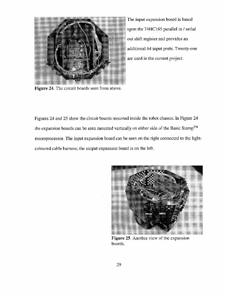
The input expansion board is based
upon the 74HC 165 parallel in / serial
out shift register and provides an
additional 64 input ports. Twenty-one
are used in the current project.
Figure 24. The circuit boards seen from above.
Figures 24 and 25 show the circuit boards mounted inside the robot chassis. In Figure 24
the expansion boards can be seen mounted vertically on either side of the Basic StampTM
microprocessor. The input expansion board can be seen on the right connected to the light-
coloured cable harness; the output expansion board is on the left.
Figure 25. Another vicw of the expansion boards.
Sensors
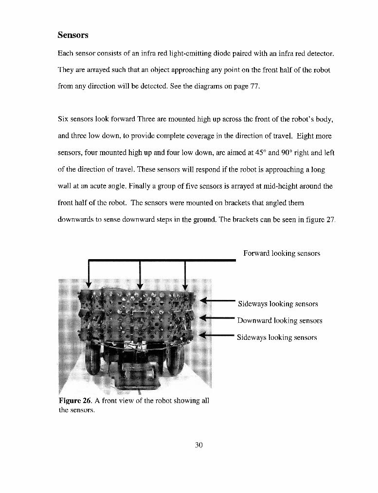
Each sensor consists of an infra red light-emitting diode paired with an infra red detector.
They are arrayed such that an object approaching any point on the front half of the robot
from any direction will be detected. See the diagrams on page 77.
Six sensors look forward Three are mounted high up across the front of the robot's body,
and three low down, to provide complete coverage in the direction of travel. Eight more
sensors, four mounted high up and four low down, are aimed at 45" and 90" right and left
of the direction of travel. These sensors will respond if the robot is approaching a long
wall at an acute angle. Finally a group of five sensors is arrayed at mid-height around the
front half of the robot. The sensors were mounted on brackets that angled them
downwards to sense downward steps in the ground. The brackets can be seen in figure 27.
Forward looking sensors
Sideways
Downwar
Sideways
looking
-d lookin
looking
sensors
g sensors
sensors
Figure 26. A front view of the robot showing all the sensors.

Downward looking sensors with cylindrical light baffles
45" left looking sensor with square plate light baffle
Figure 27. A close up of the robot from the side.
Figures 26 and 27 show the arrangement of the sensors on the robot body. Figure 26 is a
general view of the front of the robot showing all the sensors.
Figure 27 is a view from the side and shows all of the techniques used to mount the
sensors. Also visible are the methods that I used to prevent stray light from getting into the
detectors. Short cylinders surround two of the downward looking sensors, and small
square plates are fitted between the light-emitting diode (LED) and the detector on some
horizontal facing ones.

THE ROBOT - OPERATION
Overview
The main features of the electronic circuit are shown in Appendix 1. At the left of the
diagram is the Basic Stamp microprocessor. At top centre are the input shift registers that
convert the sensor output signals into a serial data stream and feed it back to the Basic
StampTM. At bottom centre are the output shift registers. They receive a serial signal from
the Basic StampTM and convert it into a parallel signal that controls the LED selection
transistors. These transistors control which light-emitting diodes (LEDs) will be
illuminated.
The user drives the robot using three controls; a start/stop switch, a manual/automatic
switch and a potentiometer for steering. These three are mounted on a hand-held control
box connected to the robot chassis by a flexible cable.
Drive Wheels
Pins 12 and 13 of the Basic StampTM each send a pulse train to the servomotors that turn
the main drive wheels. These servomotors are not shown in the diagram. If the length of
each pulse in the train is 1 Sms, the wheels remain stationary. If the pulse length is longer,
the wheels rotate in one direction, if shorter, they rotate the other way. The servomotors

are mounted between the drive wheels so, to drive the robot forwards, one motor must
rotate clockwise while the other rotates anticlockwise. That is, the pulses to one
servomotor must be lengthened while pulses to the other one are shortened. If the pulses to
both servomotors are lengthened, or shortened, by the same amount, the robot will spin on
its axis.
The length of each pulse sent to each servomotor is given by
total = manualsteering + auto + bias + speed for the left wheel
total = manualsteering + auto + bias - speed for the right wheel
L ,anua,,tee,in, is a variable length, equal for each motor, which is related to the
position of the steering wheel.
L ,,, is a variable length, equal for both wheels, generated by the program code.
The program adjusts L to steer the robot away from an obstacle and back on
course again.
L ,,, is a constant length that causes a bias to the steering to compensate for
differences between the two servomotors.
L is a length that increases L for one wheel and reduces L to,a, for the other,
and is related to the commanded speed.

Manual Steering
Manual steering is accomplished by controlling L in response to the position of
the steering wheel. Before each pulse is sent to the servomotors, capacitor C1 is recharged
through R3 and the steering potentiometer VR1. The time taken for C 1 to recharge
depends on the resistance presented by VR1, and is measured by the Basic StampTM.
Scaling and limiting transforms the measured time into the part L ,an,a,,,,e,n, of the pulse
sent to the servomotors.
Starting and Stopping
When the startlstop switch is opened, a logic 1 is applied to pinl of the Basic StampTM.
When the software code sees the logic 1 it accelerates the robot to its target speed. During
acceleration, the steering that can be applied by VRl is limited to prevent the robot from
spinning on its axis.
When the startfstop switch is closed, the software reads a logic 0 at pinl and responds by
slowing and stopping the robot. Manual steering is increasingly restricted as the speed
diminishes. Once the speed is zero, the robot enters a low power "nap" mode for 3ms
before reading the logic state at pinl again.
Automatic and Manual Modes
Opening the autolmanual switch places the robot in automatic mode by applying a logic 1
to pin 2 of the Basic StampTM. The obstacle avoidance circuit is activated and contributes
to steering the robot. Closing the switch sends a logic 0 to pin 2 and the software bypasses
the obstacle avoidance circuit. The robot is then in full manual mode and is steered by
VR1 alone.
The Output Expansion Subsystem and Light-Emitting Diodes
The output subsystem consists of two 74HC595 serial inlparallel out shift registers, eight
transistor switches Q1 to Q8, and the associated LEDs. To allow future expansion, two
shift registers are installed, although only one is in use for this project. Only transistors
Q1 and 4 2 are shown in Appendix 1.
The process of activating the LEDs (light-emitting diodes) begins by sending the binary
sequence 00000001 to the upper 74HC595 shift register via the "Select LEDs" line. A
latch pulse to the 74HC595 sends the binary sequence to the parallel outputs, turning on
Q1 and turning off 4 2 to 48.
Next, two consecutive signals are sent from the Basic StampTM by way of the "Activate
LEDs" bus. Since only Q1 is turned on, only LED1 and LED2 will light. The first signal is
a 1mS burst at 38.5kHz, the second a lms burst at a higher frequency. After each burst the
detectors PD1 to PD19 are read. Following the first signal burst, obstacles considered
"Near" are recognized. After the second the sensors detect obstacles considered "Very
Near" (See next section for a detailed explanation).
The diode Dl protects Q1 from the negative voltage component of this signal, and R5
limits the current in the LED chain to 15mA.

The binary sequence shifts to 00000010 to turn on Q2 and the sequence repeats. There are
seven groups of LEDs to signal, so after 01000000 has been sent the sequence reverts to
00000001 and the entire process begins again.
The Input Expansion Subsystem
The input expansion subsystem consists of three 74HC165 parallel in / serial out shift
registers and 19 infra red detectors. For simplicity only two shift registers are shown in the
circuit diagram, each with four detectors. Each detector includes a bandpass filter centred
on 38.5kHz and it outputs a logic 0 when illuminated with infra red light modulated at this
frequency. At frequencies other than 38.5kHz sensitivity is reduced and so an object must
be closer to the sensor before it is detected and the sensor output goes to logic 0. Now if
the sensor receives two consecutive light pulses reflected from an obstacle, one modulated
at 38.5kHz and the other modulated at a higher frequency, the robot can determine if the
obstacle is "near" or "very near." This method is not precise because the material and the
surface texture of an object also affect the distance at which it is detected.
Reading the Sensors and Storing the Results
A group of the LEDs is activated at 38.5kHz and the outputs from the sensors is read and
loaded into the 74HC165's. The string of 1's and 0's representing these states is transferred
to the Basic StampTM and stored as two binary words. Only two or three bits from these
words are important each time the sensors are scanned. For example, if LEDl and LED2
have just been fired, we are only interested in the outputs from the sensors mounted
alongside LEDl and LED2. Call these PD1 and PD2. These will tell us reliably if an
obstacle is "near" and along their line of sight. The relevant bits are transferred to longer

term storage and the two binary words are overwritten the next time that the state of the
sensors is read.
Before moving on to the next group of sensors, the same LEDs are activated again at a
higher LED modulation frequency so that "very near" obstacles may be detected. The
frequency of the second signal burst was finally set at 41.75kHz for the 45" and 90"
sideways looking sensors, and 40.5kHz for those facing forward.
When all seven groups of LEDs have been fired, the relevant bits in storage give a crude
map of obstacles around the front half of the robot and an indication of whether they are
"near" or "very near." These bits are then used to select the next incremental motion for
the robot.
Locating, Wiring and Sequencing the Sensors
The circuit diagram in Appendix 1 shows that some LEDs are wired in groups of two, and
some in groups of three. Where two are wired in series, they are mounted one above the
other and aimed horizontally to detect above ground obstacles. It does not matter if the
light emitted by the upper LED is detected by the lower sensor.
Where three LEDs are wired in series, two are aimed horizontally to detect above ground
obstacles; the third is angled downward to examine the ground for downward steps or
potholes. I made sure that the downward looking sensor was not located close to the
horizontally aimed ones. My concern was that light emitted by the horizontally aimed
LEDs and reflected by an above ground obstacle would be detected by a downward

looking sensor. The latter will interpret the light as a reflection from the ground that may
not be there, a dangerous situation. To solve this problem the downward looking LED and
its associated detector were located 90 degrees away around the circumference of the robot
from the other LEDs connected in series with it.
The sequence of firing the LEDs was carefully chosen so that, before the state of any
sensor is read, it is allowed a "dark" period of approximately 1mS when it is not
illuminated by any sensor on the robot. For example, first a group of LEDs on the left of
the robot fires and reflected light illuminates several detectors on the left. During this time
the detectors on the right are not illuminated and any residual charge in those detector
circuits has time to decay.
Detailed Description of the Code
The program that controls the robot is shown on the next page in pseudo-code form.
The main program loop is executed in lOms in automatic mode, three times faster when
manual mode is selected. It contains the instructions to:
Read the switches and potentiometer on the operator's control box
Read the infra red sensors
Make turn decisions
All other functions are handled by subroutines called directly either by the main loop, or
by other subroutines. For the full program code see Appendix 2

IF StartIStop switch is set to Stop Make a normal stop GOT0 Main
ENDlF
Read Steering Wheel
IF AutoIManual switch is set to Manual Select manual mode and move a step GOT0 Main
ENDlF
Read all the sensors
CASE 1 - An obstacle is detected Implement a turn to avoid collision and move a step GOT0 Main
CASE 2 - No obstacle is sensed AND robot is off course Implement a turn to get back on course and move a step GOT0 Main
OTHERWISE Select manual mode and move a step GOT0 Main
END

Making Turn Decisions
The sensors look at the robot's surroundings in twelve different directions and seven of
these directions are explored at two ranges. To examine every combination before
making a turn decision would be an impossible task. Instead I have adopted a hierarchical
method.
Firstly I considered the configurations of obstacles that the robot would encounter, and
placed them in three groups by priority. The high priority group includes all the situations
where the robot may encounter a downward step. Since such hazards are only detected
when the robot is close to them, these are the most urgent ones to deal with. All the
steering instructions in this group are "emergency right" or "emergency left." For these
situations the robot takes control away from the operator and is fully responsible for
manoeuvring.
The medium priority group contains the cases where the robot finds an obstacle "very
near." The steering instructions are mainly "hard right" and "hard left" and the operator is
permitted only to increase the rate of turn away from the obstacle. Two exceptions to the
"hard right" and "hard left" instructions are intended to cover cases where the robot is
moving along a corridor or close to a wall.
The first exception is where the robot senses an obstacle, possibly the wall of the corridor,
"very near" on one side only. "Slow right" and "slow left" instructions were considered
enough to steer the robot away from it again. The operator can use the steering wheel to
increase the turn initiated by the robot, but cannot counteract it and steer into the obstacle.

The second exception covers the case where the robot is in a narrowing corridor. When
obstacles are detected "very near" on both sides the robot considers the gap between them
to be too narrow to pass. It stops, backs up about lOOmm and rotates through 180" so that
it can return the way it has come. The short backup moves the sensors out of range of the
obstacles and ensures that the robot does not spin around a second time. The robot is
responsible for this manoeuvre and returns control to the operator when the obstacles are
no longer "very near."
The low priority group contains the instances in which the robot sees an obstacle that is
"near" and the robot takes avoiding action mainly with "slow left" or "slow right"
commands.
Again the exceptions cover cases where the robot is moving along a corridor or close to a
wall. If an obstacle is detected "near" but not "very near" and on one side only, the robot
will take no corrective action, but will limit the operation of the steering wheel to prevent
the operator from steering into the obstacle.
If obstacles are detected "near" but not "very near" on both left and right sides, the robot
will centre the steering wheel and steer straight ahead until either one obstacle becomes
"very near" or some new configuration of obstacles has a higher priority for avoidance.
Within each of the three groups the situations are ranked by the complexity of the
encounter. An encounter with three obstacles is given greater precedence than an
encounter with one. This is important because the robot will respond to the first logical

statement that generates a TRUE response, and will ignore all subsequent statements.
The robot searches through the high priority group, looking for a match between the sensor
readings and the statements in the group. If a match is found, the program immediately
branches to the action required. If no match is found in the high priority group, the
program explores the medium and then the low priority groups.
If all the statements in all three groups are tested against the sensor readings and no match
is found, then no obstacles are near. The robot checks to see if it is still off-course from a
previous encounter, and if so, will steer back on course. Once back on course the robot
returns full control to the operator.
Turning Back on Course
During a return to course the robot will note the direction that it is turning. If another
obstacle is detected during the manoeuver, then as long as the operator does not move the
steering wheel, the robot will continue turning in the same direction to avoid the new
obstacle.
If the operator does turn the steering wheel, the course correction manoeuver is cancelled,
the preferred course updated to the new course that the operator is steering, and the robot's
steering preference at the next obstacle is nullified. At the next obstacle the robot will
follow the operator's steering preference.

For example, suppose that the robot is steering left to get back on course when it
encounters an obstacle that it can pass on either side. If the operator has not touched the
steering wheel, the robot will turn left; if the wheel is moved, the robot will turn left or
right, whichever way the operator is steering.
Sub-Routines
The subroutines are called by the main loop and handle the robot's steering, speed control
and various housekeeping routines.
Also handled by subroutines are the decisions to turn left or right based on the direction
that the operator is steering. These executive level decisions are handled by the
subroutines simply to make the decision making section of the main loop easier to read.
Recognizing that I was considering this code as having an application in an electric
wheelchair, I smoothed most turns and speed changes by incrementing the steering and
speed variables towards their target values. The only exceptions are the emergency stops
and turns which are abrupt.

TROUBLESHOOTING
Downward Looking Sensors
The five downward looking sensors were initially mounted on brackets that angled them
down at 45" to sense downward steps in the ground. This arrangement did not work very
well, particularly if there were dark or non-reflective patches on the ground. The robot was
apt to interpret these areas as potholes and to take avoiding action. To solve the problem
small blocks were fitted behind the upper part of each angle bracket. These blocks forced
the sensors down to an angle of approximately 57" below the horizontal and that improved
their ability to detect the ground. At this angle they see the ground some 70mm ahead
which is far enough for the robot to make an emergency stop.
Sensors Activated by Stray Light
I encountered two separate problems that were traced to stray light entering a detector.
The first was a spurious response caused by the relative positioning of a LED (light-
emitting diode) and its associated detector. Unless the front of the LED projected ahead of
the detector, light scattered from the rim of the LED housing activated the adjacent
detector directly. This problem was solved by mounting a tiny light barrier between the
LED and the detector.
The second problem was caused by light being reflected from the robot's body into the
downward looking detectors. This resulted in a signal of safe ground to travel on when
there was none - a serious flaw. I cured it by mounting a short cylindrical light hood over
each downward facing detector.
Robot Moves Faster in "Manual" Mode than in "Automatic" Mode
The main loop of the software code is fully traversed only when the startlstop switch is set
to 'start' and the autolmanual switch is set to 'auto'. See page 34 for a description of the
action of these two switches. Now because much of the main loop is bypassed in manual
mode, the program completes more loops per second in manual mode than it does in
automatic. Since the robot makes one incremental move per loop of the code, it travels
faster when the switch is set to 'manual.'
To reduce the speed difference between manual and automatic modes, I located the part of
the code that is read only in automatic mode and added eight additional calls to the 'move'
subroutine. The additional calls are distributed evenly throughout the code so that the
robot's movements do not become jerky.
There is a penalty for making these additional calls because the control switches, steering
wheel, and obstacle sensors are only read once for each loop of the code. With the extra
calls, the robot makes several incremental movements between each reading of these
devices. At worst, the robot will travel an additional 5mm before responding to
commands. The operator's "feel" of the controls is not noticeably changed by this delay.
As far as the effect on collision avoidance is concerned, the delay means that when the
sensors detect an obstacle, the robot will cover 2% of the distance to it before responding.
This will not materially affect the risk of collision.

Turning Back on Course after an Obstacle
Getting the robot to turn back on course after passing an obstacle proved to be one of the
more challenging parts of the project, and the residts are not as good as I would like. In
principle, the method is to minimize the function
where the i th pulse (actually the fraction of the i th pulse which relates to automatic
steering) rotates the drive wheel through an angle 8,; This function is allowed to increase as
the robot steers to avoid an obstacle. When no obstacles are in view, the robot is steered
until the function is minimized. If the operator adjusts the steering wheel during the
manoeuver, the function is set to zero and the robot continues on the new course set by the
operator.
If' the drive wheels are driven by stepper motors, or the wheels are fitted with encoders, it
becomes an easy matter to measure the rotations 8,. In this project, however, the main
wheels are driven by servomotors so the function to be minimized is
1 ~ i , au to , left - Li, au to , r i gh t I

where Li is the length of that part of the drive pulse that relates to automatic steering.
Using this function I noted that the function varied as expected, increasing as the robot
avoided an obstacle and decreasing again as the robot came back on course. However,
when the function returned to its initial value, the robot was still not back on course.
Worse, the amount by which it was off-course was not consistent.
After lengthy testing, I found some obvious and some possible reasons for the problem.
1) Numerical Overflow. The numerical value of the function became too large for the 16-
bit memory location after the robot had turned through about 60 degrees. Dividing the
function by ten solved the problem at the expense of some precision in the course
correction ability.
2)Noise in the steering potentiometer. I noticed that the remote steering control was
susceptible to vibration. A momentary change in resistance would be interpreted as the
operator turning the steering wheel, so the program would then cancel any further course
correction. I changed the software to increase the threshold where a turn of the wheel is
signalled and this improved the noise problem somewhat. A better quality potentiometer
would be a superior solution.
3) Differences in the characteristics of the servomotors driving the main wheels. I
addressed this problem by adding a bias to the function above. The right wheel must
receive move pulses that the left before the function reaches a minimum. The solution is
not perfect as the angle between the original course steered and the course to which the

robot returns after avoiding an obstacle varies from one trial to the next. For future
projects of this type I would use stepper motors or encoders.

EXPERIMENTAL RESULTS
Prior to any formal, structured testing I needed to adjust and optimize three characteristics
on the robot.
The range at which the robot would consider an obstacle to be "very near."
The rate of turn for hard and slow turns.
The rate at which the robot would accelerate into hard and slow turns.
The first of these would be established by the correct choice of the LED modulation
frequency. The remaining two would require modifications to the body of the program
code.
To set these characteristics I performed several small experiments in which the robot
encountered single and multiple obstacles in various configurations. Following each test,
one or more of the characteristics were adjusted and the test repeated until I found a
combination of settings where, for all obstacles, the robot would:
React to an obstacle in sufficient time to avoid it.
Turn sharply enough to avoid collision but not so sharply as to be heading back the
way it had come.
Stop turning away from an obstacle as soon as possible after the threat of collision
was gone.

The final setting for "the range at which the robot would consider an obstacle to be "very
near"" was set by fixing the LED modulation frequencies for the 45", and 90" left and
right sensors, at 40.5kHz and 41.75kHz respectively. For the other two settings please
refer to the program code in Appendix 2.
Once I was satisfied with these settings I tested the robot's abilities in a more formal way
in three different environments
A tabletop with a drop on all sides.
A field of randomly placed obstacles.
A corridor with obstacles arranged along its sides
The Tabletop
When the robot approached the edge of the tabletop, it would make an emergency stop,
turn on its axis through 45" or 90" and then continue in a new direction. The emergency
stop was always quick enough to prevent the robot from going over the edge but, on
occasion, turning on its axis would cause one wheel to go over the edge. The problem was
solved making the robot back up in a straight line for a short distance before turning.
The distance backed-up was approximately lOOmm or roughly half the length of the robot
and almost exactly reversed the path followed in approaching the edge. Consequently there
was no danger of collision although the back up was made 'blind', that is without the
benefit of sensor input.
I discovered a more serious problem that concerned the colour of the surface at the bottom
50

of a step or a pothole. If the surface at the bottom is light or highly reflective, then it
reflects sufficient light to activate the detector, giving a false indication of a surface safe to
travel on, a dangerous situation. Reducing the sensitivity of the sensor caused the opposite
problem; the robot would avoid dark patches of ground, taking them for downward steps
that were not there. Not dangerous but a nuisance.
This problem might be solved in future projects by separating the LED and associated
detector and using a triangulation approach to ground detection.
The Random Obstacle Field
The obstacle field consisted of several white boxes arranged randomly on a smooth floor. I
drove the robot into the field and aimed it toward some particular exit. As the robot
progressed I noted the frequency of obstacle avoidance manoeuvres, and the extent of
operator control needed for it to reach the desired exit. The experiment was repeated with
obstacle fields with other densities and the results are shown on the next page.
For all except the second trial at 0.3m obstacle separation, the LEDs were modulated at
38.5kHz to detect 'near' obstacles, and at 40.5kHz to detect 'very near' obstacles. For the
second trial at 0.3 m obstacle separation, 41.75kHz instead of 40.5kHz was applied to the
45" and 90" left and right facing sensors. The effect was to reduce the range of these
sensors by about 60% and so allow the robot to travel in narrower corridors.

Table 2. Results with the robot in the random obstacle field.
Min separation between obstacles
l.Om (5 x robot diameter)
0.75m (3.75 x robot diameter)
0.5m (2.5 x robot diameter)
0.3m (1.5 x robot diameter) 1" trial
Side sensors modulated at 40.5kHz
0.3m (1.5 x robot diameter) 2nd trial
Side sensors modulated at 41 SkHz
Results
An easy course. Few obstacle avoidance
manoeuvres. Minimal user input
As above. Some user input
Many obstacle avoidance manoeuvres. Unable to
find the goal without much user assistance. Some
collisions.
Failed. Gaps too narrow.
Success with much user assistance but robot
motion was very jerky
The Corridor with Obstacles
Two planks of wood formed the sides of the corridor and the obstacles were three
rectangular boxes. Two were placed against one wall of the corridor and one against the
other. The spacing between adjacent pairs of boxes was roughly equal.
As before, the robot was driven though the corridor and I noted the number of obstacle
avoidance manoeuvres, and the amount of operator control needed for it to reach the exit.
The experiment was repeated with increasingly narrow corridors and the results are shown
below.

Table 3. Results with the robot in the corridor.
Width of Corridor
1.25 m (6.25 x robot diameter)
1 .O m (5 x robot diameter)
0.75 m (3.75 x robot diameter)
Side sensors modulated at 41.75kHz
0.6 m (3.0 x robot diameter)
Results -
Success. Occasional obstacle avoidance
manoeuvres, no user action taken
Success. Few obstacle avoidance
manoeuvres, little user action taken - -
Several obstacle avoidance manoeuvres,
some successes with frequent user input.
Many failures without. Narrow passages
(2.0 x robot diameter) contributed to
failures. Occasional collisions.
Failure
These results show, as expected, that the robot had more difficulty negotiating a narrow
corridor. What is not quite so obvious is the feeling of a transfer of responsibility from the
robot to the operator in the narrower corridors. When the spaces between obstacles are
large, the robot may only need to respond to one obstacle at a time. Steering instructions
are consistent and infrequent, and the operator has little to do beyond periodically updating
the course steering. When the obstacles are close together, the robot is overwhelmed by
sensor signals. Any change in direction brings a new pattern of signals, resulting in new
steering instructions. The result may be a jerky or oscillating steering which may lead to a
collision. The operator has to be vigilant to drive the robot in the direction required.

Figure 28. The robot negotiating a wide corridor without operator assistance.
Figure 29. Another trial of the unassisted robot in a wide corridor.

CONCLUSIONS
General
The robot negotiated several obstacle courses successfully although it coped better in
when the obstacles were far apart or where the corridors were wide. When the spacing
between obstacles was at least four times the robot's diameter, it avoided collisions
reliably, returned to its previous course, and worked in cooperation with the human
operator. If the operator had no preference it made its own turn decisions to stay on course,
but always deferred to the operator if the steering wheel was turned.
In confined spaces the robot was frequently overwhelmed by signals from the sensors and
this caused it to have difficulty with the course. I made many adjustments to sensor range
and steering characteristics to make the robot behave well in all courses but the exercise
was not wholly successful.
In the introduction I noted that the infra red sensors should be replaced with ultrasonic
ones for a full sized project. To store range information from an ultrasonic sensor would
require one byte per sensor, whereas the infra-red sensors on this project need only two
bits per sensor. The additional memory space is not available on the Basic StampTM IIsx
with my current program code because it uses 97% of the space allocated for variables.

It is worthwhile to note that while my program code uses 97% of the space for memory
variables, only 9% of program space is occupied, hardly an efficient use of the chip's
resources.
This project has shown that a very small computer can take on minor navigational tasks
and collision avoidance in a model robot, but that the Basic StampTM is not a suitable
choice for a full-scale robotic wheelchair.
Specific Suggestions for Future Projects
Valuable improvements may be realized by replacing the infra-red sensors with ultrasonic
ones which, although more costly, would supply an accurate range to each obstacle
detected.
For future projects I suggest using a microprocessor such as the Javelin StampTM or the
Motorola MC68HC11 although both are more expensive that the Basic StampTM IIsx. Both
have 32k memory - twice a much as the Basic StampTM IIsx - and it is shared by the
program and memory variables, a more efficient use of memory space.
I recommend using stepper motors rather than servomotors to improve the robot's ability
to return to a previous course. Servomotors without position feedback, as used in this
project, have not allowed the robot to return to a previous course accurately. Servomotors
with encoders would be acceptable but require additional 110 ports.
I suggest wiring the downward looking sensors so that they are independent of the
forward-looking ones. This approach will use a little more power and require extra lines of
software code. Nevertheless, these disadvantages are more than outweighed by the
benefits. Firstly, the sensitivity of the downward sensors can then be adjusted
independently of the forward-looking ones. Secondly, the sensitivity of each of the
forward and sideways looking sensors can be adjusted separately without affecting the
downward looking sensors. In this way, the robot's overall zone of sensitivity can be
shaped to suit the environment.

APPENDICES
Appendix 1 . . . . . . . . . . . . . . . . . . . . . . . . . . . . . . . . . . . . . . . . . Electronic Circuit Diagram
Appendix 2 . . . . . . . . . . . . . . . . . . . . . . . . . . . . . . . . . . . . . . . . . . . . . . . . . . . Program Code
Appendix 3 . . . . . . . . . . . . . . . . . . . . . . . . . . . . . . . . . . . . . . . . . . . . . . . . . Sensor Schedule
Appendix 4 . . . . . . . . . . . . . . . . . . . . . . . . . . . . . . . . . . . . . . . . . . . . . . . . Turn Instructions

APPENDIX 1
Electronic Circuit Diagram


APPENDIX 2
Program Code

'{$stamp bs2sx) ' - - - - - _ - Declare motion variables ----------------- ------ Leftwheel CON 12 Rightwheel CON 13 Highspeed CON 250 LowSpeed CON 150 SetSpeed VAR BYTE Speed VAR BYTE 'speed that the robot is actually making ManlSteer VAR WORD 'fully manual steering direction ManISteerPrev VAR WORD 'previous value of ManlSteer Autosteer VAR WORD 'steering controlled by sensor input Biassteer CON 1323 'steering bias to compensate for servo imbalance Zerosteer CON 32766 'shifted zero for Autosteer and AccmSteer to avoid
overflow LimtSteer VAR WORD 'manual steering but range limited by sensor
input CntrSteer CON 21 95 'value of RCTIME with steering wheel centred AccmSteer VAR WORD 'steering change accumulated by automatically
avoiding obstacles PrefSteer VAR NIB 'the robot's preferred steering direction (O=none,
1 =left, 2=right) ReverseGearVAR BIT '1 =reverse, O=forward I Declare 110 variables ------- D-out Clock Latch SigtoLED D-in Load Pattern SensrHigh SensrLow LowFreq HiFreq Freq indx AAA BBB CCC DDD EEE FFF GGG AA BB
CON CON CON CON CON CON VAR VAR VAR CON CON VAR VAR VAR VAR VAR VAR VAR VAR VAR VAR VAR
3 4 5 6 9 11 byte word byte 1 54 162 WORD WORD BIT BIT BIT BIT BIT BIT BIT BIT BIT
'Data out to 74HC595 pin 14 'Clock to 74HC595 pin 1 1 & 74HC165 pin 2 'Latch to 74HC595 pin 12 'Signal to IR LEDs 'Data in from 74HC165 pin 9 'Load sensor states, 74HC165 pin 1 'LED selector 'First 16 sensor signals 'Remaining 8 sensor signals 'IR frequency for long range 'IR frequency for short range 'Actual IR transmitting freq 'loop counter 'Near obstacle 'Near obstacle 'Near obstacle 'Near obstacle 'Near obstacle 'Near obstacle 'Near obstacle 'Very near obstacle 'Very near obstacle

CC VAR BIT 'Very near obstacle DD VAR BIT 'Very near obstacle EE VAR BIT 'Very near obstacle FF VAR BIT 'Very near obstacle GG VAR BIT 'Very near obstacle a VAR BIT 'Downward step b VAR BIT 'Downward step d VAR BIT 'Downward step f VAR BIT 'Downward step g VAR BIT 'Downward step i VAR WORD I _ _ _ _ _ _ _ Initialize motion variables --------- INPUT 0 'robot stays still when powered up INPUT 1 'robot starts in manual mode SetSpeed = 0 LimtSteer = CntrSteer 'Start with steering wheel centred Autosteer = ZeroSteer AccmSteer = ZeroSteer PrefSteer = 0 'robot has no steering preference ReverseGear = 0 I ------- Initialize I10 variables ---- SensrHigh = %0000000000000000 SensrLow = %00000000
I- - - - - Main routine - -------------- main: ReverseGear = 0 'reverse mode is off IF in0 = 0 THEN Normalstop 'start switch on the remote is set to stop GOSUB Readsteeringwheel 'start switch on the remote is set to start IF in1 = 0 THEN manual 'manuallauto switch on the remote is set to
manual
I------ Read all the sensors -------- GOSUB Chkspeed
Pattern = %00000001 GOSUB ScanSensrLo AAA=SensrLow.Bit5 & SensrLow.Bit6 'A or leftlleft a=SensrLow.Bit7 'a or frontldown GOSUB ScanSensrHigher AA=SensrLow.Bit5 & SensrLow.Bit6 'A or leftheft
GOSUB Chkspeed
Pattern = %00000010
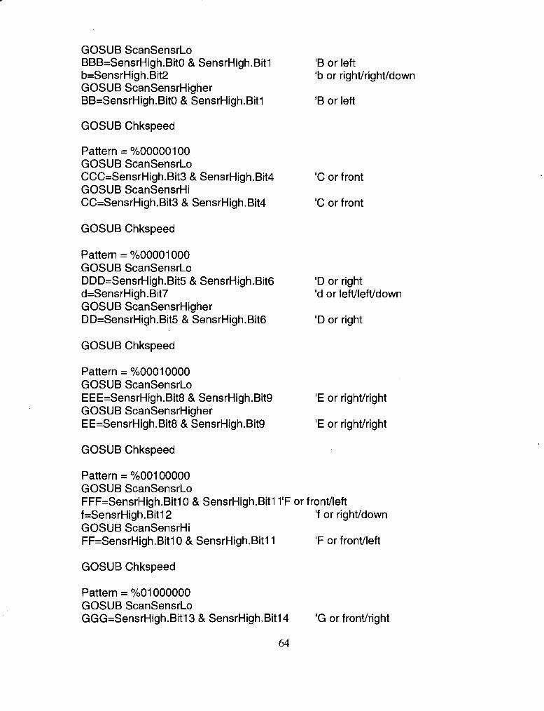
GOSUB ScanSensrLo BBB=SensrHigh.BitO & SensrHigh.Bit1 b=SensrHigh.Bit2 GOSUB ScanSensrHigher BB=SensrHigh.BitO & SensrHigh.Bit1
GOSUB Chkspeed
Pattern = %00000100 GOSUB ScanSensrLo CCC=SensrHigh.Bit3 & SensrHigh.Bit4 GOSUB ScanSensrHi CC=SensrHigh.Bit3 & SensrHigh.Bit4
GOSUB Chkspeed
Pattern = %00001000 GOSUB ScanSensrLo DDD=SensrHigh.Bit5 & SensrHigh.Bit6 d=SensrHigh.Bit7 GOSUB ScanSensrHigher DD=SensrHigh.Bits & SensrHigh.Bit6
GOSUB Chkspeed
Pattern = %00010000 GOSUB ScanSensrLo EEE=SensrHigh.Bit8 & SensrHigh.Bit9 GOSUB ScanSensrHigher EE=SensrHigh.Bit8 & SensrHigh.Bit9
'B or left 'b or rightlrightldown
'B or left
'C or front
'C or front
'D or right 'd or leftlleftldown
'D or right
'E or rightlright
'E or rightfright
GOSUB Chkspeed
Pattern = %00100000 GOSUB ScanSensrLo FFF=SensrHigh.BitlO & SensrHigh.Bit1 1'F or frontlleft f=SensrHigh.Bitl2 'f or rightldown GOSUB ScanSensrHi FF=SensrHigh.Bitl 0 & SensrHigh.Bitl1 'F or frontlleft
GOSUB Chkspeed
Pattern = %01000000 GOSUB ScanSensrLo GGG=SensrHigh.Bitl3 & SensrHigh.Bitl4 'G or frontlright

g=SensrHigh.Bit 1 5 'g or IefVdown GOSUB ScanSensrHi GG=SensrHigh.Bitl3 & SensrHigh.Bitl4 'G or fronvright
GOSUB Chkspeed
'______ ------ Decisions about obstacles ahead ====== I------ High priority IF a=l AND (d=l OR g=l OR AAA=O OR FFF=O OR BBB=O) THEN EmergencyRightSO IF a=l AND (f=l OR b=l OR EEE=O OR GGG=O OR DDD=O) THEN EmergencyLeftSO IF a=l THEN EmergencyLeftEmergencyRight IF f=l OR b=l THEN EmergencyLeft45 IF g=l OR d=l THEN EmergencyRight45
I------ Medium priority IF ((AA=O OR BB=O) AND (DD=O OR EE=O)) THEP
'Corridor 4 EmergencyRight
IF (FF=O OR CC=O OR GG=O) AND (BBB=O OR AAA=O) THEN HardRight 'ahead and (left or leftheft)
IF (FF=O OR CC=O OR GG=O) AND (DDD=O OR EEE=O) THEN HardLeft 'ahead and (right or righthight)
IF (FF=O OR CC=O OR GG=O) AND PrefSteer = 1 THEN HardLeft 'partial ahead
IF (FF=O OR CC=O OR GG=O) AND PrefSteer = 2 THEN HardRight 'partial ahead
IF (FF=O OR CC=O OR GG=O) AND PrefSteer = 0 THEN HardLeftHardRight 'partial ahead
IF (AA=O OR BB=O) AND (EE=1 AND DD=1) THEN Slowright 'IefVleft or left only
IF (EE=O OR DD=O) AND (AA=1 AND BB=1) THEN Slowleft 'righvright or right only
t___- - - Low Priority IF (FFF=O OR CCC=O OR GGG=O) AND (BBB=O OR AAA=O) THEN SlowRight
'ahead and (left or leftheft) IF (FFF=O OR CCC=O OR GGG=O) AND (DDD=O OR EEE=O) THEN
SlowLeft 'ahead and (right or righvright)
IF (FFF=O OR CCC=O OR GGG=O) AND PrefSteer = 1 THEN SlowLeft 'partial ahead
IF (FFF=O OR CCC=O OR GGG=O) AND PrefSteer = 2 THEN SlowRight 'partial ahead
IF (FFF=O OR CCC=O OR GGG=O) AND PrefSteer = 0 THEN SlowLeftSlowRight

'partial ahead
IF ((AAA=O OR BBB=O) AND (DDD=O OR EEE=O)) THEN NoLeftNoRight 'Corridor
IF (AAA=O OR BBB=O) AND PrefSteer = 2 THEN SlowRight'leftIleft or left IF (AAA=O OR BBB=O) THEN Noleft 'leftheft or left IF (EEE=O OR DDD=O) AND PrefSteer = 1 THEN SlowLeft 'righthight or right IF (EEE=O OR DDD=O) THEN Noright 'rightlright or right
I------ In the clear IF (AccmSteer < (ZeroSteer-85)) THEN CorrectRight 'Accumulated steering is to
the left and robot is in auto mode IF (AccmSteer > (ZeroSteer+65)) THEN CorrectLeft 'Accumulated steering is to
the right and robot is in auto mode GOT0 Manual
Readsteeringwheel: ManlSteerPrev = ManlSteetcopy current value to previous value HIGH 2 'discharge the capacitor PAUSE 1 RCTIME 2,l ,Madsteer 'store the wheel position IF ((ManlSteerPrev - ManlSteer)c40 OR (ManlSteerPrev - ManlSteer)>65505)
THEN NotTurned 'Steering wheel has not been turned GOSUB WheelTurned
NotTurned: RETURN
ScanSensrLo: 'Long range scan Freq = LowFreq * 100 GOSUB ScanSensrGroup RETURN
ScanSensrHi: 'Short range scan Freq = HiFreq * 100 GOSUB ScanSensrGroup RETURN
ScanSensrHigher: 'Short range scan for side-looking sensors Freq = 170 * 100 GOSUB ScanSensrGroup RETURN
ScanSensrGroup: HlGH Load '74HC165 loads on a hi to lo transition
66

SHIFTOUT D-out, Clock,MSBFirst, [pattern\l 6I'select the LEDs PULSOUT Latch,3 FREQOUT SigtoLED,Z,Freq 'transmit to LEDs PULSOUT Load,3 'read the sensors SHIFTIN D-in,Clock,MSBPre,[SensrHigh\l6,SensrLow\8] 'return sensor
signals to STAMP RETURN
Manual: PrefSteer = 0 'robot has no preferred direction to steer GOSUB SmoothLimtSteer GOSUB SmoothAutoSteer AccmSteer = Zerosteer SetSpeed = Highspeed GOSUB ChkSpeed GOT0 Main
ChkSpeed: IF SetSpeedSpeed THEN Faster IF SetSpeed4peed THEN Slower GOSUB Move RETURN
Faster: Speed = (Speed + 4) MAX SetSpeed GOSUB Move RETURN
Slower: Speed = (Speed - (4 MAX Speed)) MIN SetSpeed 'To prevent
underflow GOSUB Move RETURN
Move: PULSOUT LeftW heel,(4330-LimtSteer)/4+BiasSteer+AutoSteer-ZeroSteer+Speed-((Spee d+l00)
*ReverseGear) PULSOUT RightW heel, (4330-LimtSteer)/4+BiasSteer+AutoSteer-ZeroSteer-Speed+((Spe ed+l00)
*ReverseGear) AccmSteer = AccmSteer + (Autosteerll 0) - (Zerosteer11 0) RETURN

Normalstop: SetSpeed = 0 GOSUB Steerstraight GOSUB SmoothAutoSteer IF (Speed = 0 AND in0 = 0) THEN Rest GOSUB ChkSpeed GOT0 Main
Rest: NAP 3 GOT0 main
EmergencyLeftSO: PAUSE 1000 Speed = 0 LimtSteer = CntrSteer 'take control away from the operator and
centre the steering wheel Autosteer = Zerosteer 'Zero the autosteer ReverseGear = 1 'reverse FOR i=l TO 200
IF (in0 = 0 OR in1 = 0) THEN Maitkbort if stop or manual is selected GOSUB MOVE
NEXT ReverseGear = 0 'Forward PAUSE 500 AutoSteer = Zerosteer-1 OO1autosteer left FOR i=l TO 385
IF (in0 = 0 OR in1 = 0) THEN Main GOSUB Move
NEXT PAUSE 1000 GOT0 main
EmergencyLeft45: PAUSE 1000 Speed = 0 LimtSteer = CntrSteer 'take control away from the operator and
centre the steering wheel Autosteer = Zerosteer 'Zero the autosteer ReverseGear = 'reverse FOR i=l TO 200
IF (in0 = 0 OR in1 = 0) THEN Main GOSUB MOVE
NEXT ReverseGear = 0 'Forward

PAUSE 500 AutoSteer = Zerosteer-1 OO'autosteer left FOR i=l TO 195
IF (in0 = 0 OR in1 = 0) THEN Main GOSUB Move
NEXT PAUSE 1000 GOT0 main
EmergencyRight90: PAUSE 1000 Speed = 0 LimtSteer = CntrSteer 'take control away from the operator and
centre the steering wheel Autosteer = Zerosteer 'Zero the autosteer ReverseGear = 1 'reverse FOR i=l TO 200
IF (in0 = 0 OR in1 = 0) THEN Main GOSUB MOVE
NEXT ReverseGear = 0 'Forward PAUSE 500 Autosteer = ZeroSteer+100 'autosteer right FOR i=l TO 385
IF (in0 = 0 OR in1 = 0) THEN Main GOSUB Move
NEXT PAUSE 1000 GOT0 main
EmergencyRight45: PAUSE 1000 Speed = 0 LimtSteer = CntrSteer 'take control away from the operator and
centre the steering wheel Autosteer = Zerosteer 'Zero the autosteer ReverseGear = 1 'reverse FOR i=l TO 200
IF (in0 = 0 OR in1 = 0) THEN Main GOSUB MOVE
NEXT ReverseGear = 0 'Forward PAUSE 500 Autosteer = ZeroSteer+100 'autosteer right FOR i=l TO 195

IF (in0 = 0 OR in1 = 0) THEN Main GOSUB Move
NEXT PAUSE 1000 GOT0 main
EmergencyRightl80: PAUSE 1000 Speed = 0 LimtSteer = CntrSteer 'take control away from the operator and
centre the steering wheel Autosteer = Zerosteer 'Zero the autosteer ReverseGear = 1 'reverse FOR i=l TO 200
IF (in0 = 0 OR in1 = 0) THEN Main GOSUB MOVE
NEXT ReverseGear = 0 'Forward PAUSE 500 Autosteer = ZeroSteer+100 'autosteer right FOR i=l TO 760
IF (in0 = 0 OR in1 = 0) THEN Main GOSUB Move
NEXT PAUSE 1000 GOT0 main
HardLeft: SetSpeed = LowSpeed LimtSteer = ManlSteer MIN CntrSteer MAX (CntrSteer+(4*Speed)) AutoSteer = (Autosteer-20) MIN (Zerosteer-Speed) GOSUB ChkSpeed GOT0 main
HardRight: SetSpeed = LowSpeed LimtSteer = ManlSteer MAX CntrSteer MIN (CntrSteer-(4*Speed)) AutoSteer = (Autosteer+20) MAX (ZeroSteer+Speed) GOSUB ChkSpeed GOT0 main
SlowLeft: LimtSteer = ManlSteer MIN CntrSteer MAX (CntrSteer+(4*Speed)) SetSpeed = Highspeed AutoSteer = (Autosteer-1 5) MIN (Zerosteer-(Speedl2))

GOSUB ChkSpeed GOT0 main
SlowRight: LimtSteer = ManlSteer MAX CntrSteer MIN (CntrSteer-(4*Speed)) SetSpeed = HighSpeed AutoSteer = (Autosteer+l5) MAX (ZeroSteer+(Speed/Z)) GOSUB ChkSpeed GOT0 main
CorrectLeft: PrefSteer = 1 'Robot prefers to steer left SetSpeed = HighSpeed AutoSteer = (Autosteer-1 5) MIN (Zerosteer-(Speedl2)) GOSUB ChkSpeed GOT0 main
CorrectRight: PrefSteer = 2 'Robot prefers to steer right SetSpeed = HighSpeed AutoSteer = (Autosteer+l5) MAX (ZeroSteer+(Speed/2)) GOSUB ChkSpeed GOT0 main
NoLeft: LimtSteer = ManlSteer MAX CntrSteer MIN (CntrSteer-(4*Speed)) SetSpeed = HighSpeed GOSUB ChkSpeed GOT0 main
NoRight: LimtSteer = ManlSteer MIN CntrSteer MAX (CntrSteer+(4*Speed)) SetSpeed = HighSpeed GOSUB ChkSpeed GOT0 main
NoLeftNoRight: LimtSteer = CntrSteer SetSpeed = HighSpeed GOSUB ChkSpeed GOT0 main
'Centre the steering wheel
SlowLeftHardRight: IF ManlSteer > CntrSteer THEN SlowLeft 'Left if operator is
steering right

GOT0 HardRight 'Else right
SlowRightHardLeft: IF ManlSteer < CntrSteer THEN SlowRight 'Right if operator is steering
right GOT0 HardLeft 'Else left
EmergencyLeftEmergencyRight: IF ManlSteer < CntrSteer THEN EmergencyRightSO 'Right if operator is
steering right GOT0 EmergencyLeftSO 'Else left
HardLeftHardRight: IF ManlSteer < CntrSteer THEN HardRight 'Right if operator is steering
right GOT0 HardLeft 'Else left
SlowLeftSlowRight: IF ManlSteer < CntrSteer THEN SlowRight 'Right if operator is steering
right GOT0 SlowLeft 'Else left
W heelTurned: AccmSteer = ZeroSteer 'Zero the accumulated steering if the operator
sets a new course PrefSteer = 0 'robot relinquishes the preferred steering direction RETURN
SmoothLimtSteer: IF LimtSteer < ManlSteer THEN LimtSteerUp
LimtSteer = LimtSteer-100 MIN ManlSteer MAX (CntrSteer+(4*Speed)) 'limit steering range during acceleration so robot does not spin
RETURN LimtSteerUP:
LimtSteer = LimtSteer+100 MAX ManlSteer MIN (CntrSteer-(4*Speed)) 'limit steering range during acceleration so robot does not spin
RETURN
SmoothAutoSteer: IF AutoSteer < ZeroSteer THEN AutoSteerUp
Autosteer = Autosteer-1 5 MIN Zerosteer 'Autosteer must be higher then ZeroSteer
RETURN AutoSteerUp:
AutoSteer = AutoSteer+l5 MAX ZeroSteer glAutoSteer must be

lower then Zerosteer RETURN
Steerstraight: IF LimtSteer < CntrSteer THEN LimtSteerUp2
LimtSteer = LimtSteer-20 MIN CntrSteer 'limit steering range during acceleration so robot does not spin
RETURN LimtSteerUP2:
LimtSteer = LimtSteer+20 MAX CntrSteer 'limit steering range during acceleration so robot does not spin
RETURN

AP
PE
ND
IX 3
Sens
or S
ched
ule
Bas
ic S
tam
pTM
Pat
tern
sent
from
the
goes
to 7
4HC
165
Chi
p #
on c
able
al
low
s the
se L
ED
s to
.fir
e T
he si
gnal
from
the
dete
ctor
I A
Hig
h 3
4
A L
ow
3 5
I a D
ownw
ard
13
C H
igh
2 14
C L
ow
2 3
D H
igh
2 4
D L
ow
2 5
d D
ownw
ard
2 6
and
mem
ory
vari
able

Pat
tern
sen
t fro
m th
e I
Bas
ic S
tam
pTM
000
1000
0
allo
ws t
hese
LE
Ds
to f
ire
The
sig
nal f
rom
the
dete
ctor
an
d m
emor
y I
I I
f D
ownw
ard
I1
E H
igh
E L
ow
F H
igh
F L
ow
vari
able
1
goes
to 7
4HC
165
1 1 1 1
G H
igh
14
I S
ensr
Hig
h.B
itl3
I
g D
ownw
ard
I Sens
rHig
h.B
itl.5
I
G L
ow
1 5
Sens
rHig
h.B
it 14


APPENDIX 4
Turn Instructions
N.B In this table "any" means either 45" or 90" from straight ahead
Preference
Robot's Action
Preference I I I High Priority Situations ( I I Front and any left 1 Ignored I
- -
Ignored
Front and any right Ignored
Right
Ignored
Front only Ignored Emergency right 90"
Front only
45" or 90" left
Ignored Emergency left 90"
Ignored Emergency right 45" I 45" or 90" right Ignored Emergency left 45" -
Hard right
Medium Priority
Front and any left Ignored -
Ignored
Ignored Front and any right Hard left Ignored
Ignored
Left
Emergency right 180" Any left and any right I Ignored I
Hard left
Right Hard right
Hard left Ignored
Ignored Hard right
Slow right
Front only I Right I
Ignored Any left I Ignored
Slow left Ignored Any right Ignored

Obstacle Configuration
Low priority
Operator's
Preference
/ Action Robot's
Preference
Front and any left
Front and any right
Front only
Front only
Front only
Front only
Any left and any right
Any left
Any left
Any right
Slow right
Slow left
Slow left
Slow right
Slow left
Slow right
Ignored
Ignored
None
None
Left
Right
Any right
Ignored
Ignored
Left
Right
Ignored
Ignored
Ignored
Ignored
Ignored
Ignored
Ignored
Ignored I No left or right - -
Left
Right
Left
Right
No left
Slow right
Slow left
No right

BIBLIOGRAPHY
[I] Vijay Kumar, Tariq Rahman, and Venkat Krovi. "Assistive Devices for People
with Motor Disabilities." Wiley Encyclopaedia of Electrical and Electronic
Engineering, Assistive Devices for People with Motor Disabilities. Kumar,
Rahman, and Krovi. 1997
[2] Axel Lankenau and Thomas Rofer. "A Versatile and Safe Mobility Assistant."
IEEE Robotics and Automation Magazine. March 2001. pp 29 - 35
[3] G. Bourhis, 0. Horn, 0. Habert and A. Pruski. "An Autonomous Vehicle for
People with Motor Disabilities." IEEE Robotics and Automation Magazine.
March 2001. pp 20 - 28
[4] Edward Cheung and Vladimir J. Lumelsky. "Proximity Sensing in Robot
Manipulator Motion Planning: System and Implementation Issues". IEEE
Transactions on Robotics and Automation. Vol5. No 6. Dec 1989. pp 740 - 751

[5] Edward Cheung and Vladimir J. Lumelsky. "Real-Time Collision Avoidance in
Teleoperated Whole-Sensitive Robot Arm Manipulators". IEEE Transactions
on Systems, Man and Cybernetics. Vol23. No 1. 1993. pp 194 - 203
[6] Edward Cheung and Vladimir J. Lumelsky. "A Sensitive Skin System for
Motion Control of Robot Arm Manipulators". Robotics and Autonomous
Systems. Vol9. 1992. pp 9-32
[7] Homayoun Seraji, Ayanna Howard and Edward Tunstel. "Safe Navigation on
Hazard Terrain". Proceedings of the 2001 IEEE International Conference on
Robotics and Automation, Seoul, Korea. May 21 -26 2001. pp 3084 - 3091
[8] Homayoun Seraji, Ayanna Howard and Edward Tunstel. "Fuzzy Rule-Based
Reasoning for Rover Safety and Survivability". Proceedings of the 2001 IEEE
International Conference on Robotics and Automation, Seoul, Korea. May 21 -
26 2001. pp 1413 - 1420
[9] Homayoun Seraji. "Traversability Index: A New Concept for Planetary Rovers".
Proceedings of the 1999 IEEE International Conference on Robotics and
Automation, Detroit, Michigan, USA. May 1999. pp2006 - 2013


![Collaborative manufacturing with physical human–robot ... · operator, i.e., manual welding. In [25], a physically interactive controller is developed for a manipulator robot arm:](https://static.fdocuments.us/doc/165x107/5f121520ea0dfe1548265535/collaborative-manufacturing-with-physical-humanarobot-operator-ie-manual.jpg)


![F-MINIMAL SETS€¦ · The Sturmian minimal sets [9] and the minimal set of Jones [8, 14.16 to 14.24] are F-minimal sets. A discrete substitution minimal set is an F-minimal set if](https://static.fdocuments.us/doc/165x107/6084f15854f7005dbc1e3da1/f-minimal-sets-the-sturmian-minimal-sets-9-and-the-minimal-set-of-jones-8-1416.jpg)
