An iconomkal Answer For 1a;nta;ning Qual;V Coolant,infohouse.p2ric.org/ref/30/29065.pdfAn iconomkal...
6
7- \ i,' ' -- 3 September/October 1989 18/FN \ An iconomkal Answer For 1a;nta;ning Qual;V Coolant, joseph €/-Hindi Manager of Engineering FILTERTECH, INC. Manlius. NY ositive barrier, conveyor supported, P flatbed filtration is currently used in several industriesrequiringfiltration through disposable or permanent medias. Flow rates on such systems range from 20 CPM to several thousand GPM. Wire drawing, metal rolling, machining, grinding and heat treating are the major processes which benefit from the advantages of these systems. OPERATION As shown below, the dirty solution is transferred to the bed of the filter unit. The bed is equipped with a conveyor sys- tem to handle the internal load from the filter process, and support, disposable or permanent filter media. As ditty solution is transferred to the unit, the head of the liquid above the media drives solution through tile barrier leaving dirt deposits to form a filter cake on the media. When utilizingairvacuum, the head of the liquid the media are the driving mechanizers. The combination of the media and filter cake act as a depth filter to trap particu- late which contaminates the solution to be filtered. As the cake forms, the dif- ferential pressure across the barrier increases. The increasecauses the liquid level in the filter to rise. At a predetermined height of liquid or pressure differential, the con- veyor is engaged causing a short index of new media into the filter pool. The pro- cess then repeats. as well as the pull of vacuum underneath GRAVITY FILTER , AIR VACUUM FILTER m-m mm PU e. on the capability of the unit to pass a cer- tain GPM through a square foot of filter media Forexample, when filteringoilversus water soluble coolant, the hydraulic load on the media is much higher, therefore, a lower GPM per square foot would be used. When filtering water with large sized par- ticles where the filter cake is very porous, SIZING Regardless of whether the filter is gravity or vacuum, the filter size is based
Transcript of An iconomkal Answer For 1a;nta;ning Qual;V Coolant,infohouse.p2ric.org/ref/30/29065.pdfAn iconomkal...

7- \ i,' ' -- 3 September/October 1989 18/FN
\
An iconomkal Answer For 1a;nta;ning Qual;V Coolant,
joseph €/-Hindi Manager of Engineering FILTERTECH, INC. Manlius. NY
ositive barrier, conveyor supported, P flatbed filtration is currently used in several industries requiring filtration through disposable or permanent medias. Flow rates on such systems range from 20 CPM to several thousand GPM. Wire drawing, metal rolling, machining, grinding and heat treating are the major processes which benefit from the advantages of these systems.
OPERATION As shown below, the dirty solution is
transferred to the bed of the filter unit. The bed is equipped with a conveyor sys- tem to handle the internal load from the filter process, and support, disposable or permanent filter media. As ditty solution is transferred to the unit, the head of the liquid above the media drives solution through tile barrier leaving dirt deposits to form a filter cake on the media. When utilizingairvacuum, the head of the liquid
the media are the driving mechanizers. The combination of the media and filter cake act as a depth filter to trap particu- late which contaminates the solution to be filtered. As the cake forms, the dif- ferential pressure across the barrier increases. The increase causes the liquid level in the filter to rise. At a predetermined height of liquid or pressure differential, the con- veyor i s engaged causing a short index of new media into the filter pool. The pro- cess then repeats.
as well as the pull of vacuum underneath GRAVITY FILTER
, AIR VACUUM FILTER
m-m mm
PU e. on the capability of the unit to pass a cer- tain GPM through a square foot of filter media Forexample, when filteringoilversus water soluble coolant, the hydraulic load
on the media is much higher, therefore, a lower GPM per square foot would be used. When filtering water with large sized par- ticles where the filter cake is very porous,
SIZING Regardless of whether the filter i s
gravity or vacuum, the filter size is based
SCptembdOctober 1989 - a high CPM per square foot can be used.
When comparing the different style filters (gravity, medium vacuum, high vac- uum), the allowable GPM per square foot forthe same type solutionvaries. Utilizing a gravity filter where only the head of the liquid is the driving mechanism, a lower GPM per square foot would be required. Utilizing air vacuum where the driving mechanism is liquid head as well as vacuum a higher CPM per square foot is allowed.
Because so many variables effect the sizing of this equipment, it is some times advisable to have a filter flow test per- formed on the solution in question.
d ' Cl tTFK PO01
FN/l9
i DEtP 2 4 " FILTER PO01 I I
GRAVITY FILTERS The GF utilizes ashallower liquid pool
as compared to the DBCF and is used for smaller flow rates or light dirt load ap- plications. The unit utilizes approx- imately 8" of liquid pool to create the required differential across the media. The DBCF utilizes approximately 24" liquid pool which is 3 times the head of the GF, resulting in higher filtering capacity. Both units are used for lighter applications, with the DBGF capable of handling the more demanding of these applications.
The main advantage of a gravity type filter in lieu of air vacuum is the initial capital cost savings. When properly sized, the units will filter efficiently, however, in most cases the discharge swarf exiting the unit will retain loose solution, possibly caus- ing problems for collection and disposal of the spent media. Another advantage is that the unit does not have to be elevated to overcome vacuum. Therefore, a low profile allowing direct solution return from machines is possible without additional reservoirs.
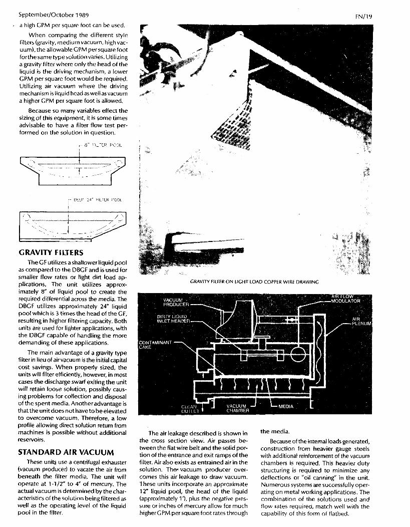
STANDARD AIR VACUUM These uniQ use a centrifugal exhauster
(vacuum producer) to vacate the air from beneath the filter media. The unit will operate at 1-1/2" to 4" of mercufy. The actual vacuum is determined by the char- acteristics of the solution being filtered as well as the operating level of the liquid pool in the filter.
GRAVITY FILTER ON LIGHT LOAD COPPER WIRE DRAWING
The air leakage described is shown in the cross section view. Air passes be- tween the flat wire belt and the solid por- tion of the entrance and exit ramps of the filter. Air also exists as entrained air in the solution. The vacuum producer over- comes this air leakage to draw vacuum. These units incorporate an approximate 12" liquid pool, the head of the liquid (approximately l'), plus the negative pres- sure or inches of mercury allow for much higher GPM per square foot rates through
the media.
Because of the internal loads generated, construction from heavier gauge steels with additional reinforcement of the vacuum chambers i s required. This heavier duty structuring i s required to minimize any deflections or "oil canning" in the unit. Numerous systems are successfully oper- ating on metal working applications. The combination of the solutions used and flow rates required, match well with the capability of this form of flatbed.

20/FN
' HIGH AIR VACUUM Operation of these filters require vac-
uums in the range of 4" to 8" of mercury. The design characteristics vary from the standard vacuum unit to allow operation underthe highervacuum. The concept of operation is similar to standard vacuum, however, due to the higher vacuum, there is a greater load on the filter conveyor. Stan- dard vacuum units utilize a flat wire belt conveyor which has load limitations. The load limitations are based on a per foot width of conveyor. Once the length of conveyor causes the total per foot width load to exceed the allowable load for the flat wire belt, the design must be altered to prevent flat wire belt stretching.
This is accomplished with three basic designs.
The first, maintains a shorterfilter bed so that the overatl load on the conveyor i s minimized. To handle the higher flow rates, greater filter area is required, therefore, the filter is made wider. The conveyor is supported in the vacuum chamber by heavy duty support rollers. The filter body is made of heavier gauge steel and stif- fened properly to guard against oil canning.
1 FILTER MDER FOR HIGHER CAPACITY
MAX ALLOWABLE LENGTH BEFORE STRETCHING OF BELT 1
When increasingthe width of the filter is not permissible or the overall filter area is not sufficient for higher flow rates, a bridge bar type filter can be used. One version of this design utilizes a complete bridge bar conveyorto support the exces- sive loads generated by high vacuum as shown below.
Specially fabricated conveyor flights are manufactured and driven by heavy duty roller chain on each side of the filter. The conveyor flights (bars) are tracked on each side of the filter allowing the flights to act as a bridge to handle the load generated by the high vacuum. This is shown in the figures below.
A second version of the bridge bar filter is to utilize two conveyors, standard
September/October 1989
- ---
FILTERTECH MODEL SCF AIR VACUUM FILTER ON MODERATE LOAD COPPER WIRE DRAWING
type heavy duty flat wire belt with an aux- iliary bridge type conveyor underneath. The auxiliary conveyor supports the flat wire belt handlingthe high loads. By using the flat wire belt on the entrance and exit ramps, air loss i s kept to a minimum. This results in high efficiency operation under high vacuum loads.
H E A V Y C U T Y - - FLAT WIRE BFl 1 TON K Y O H
High vacuum filters have found great success on applications such as aluminum and steel rolling mills where the filter de- mand is quite high due to large flow rates. Other applications are aluminum wire drawing and alloy fine grindingwherevis- cous oils are the solutions to be filtered.
SPECIAL CHARACTERISTICS As described earlier, regardless of the
type of filter, the concept of this style sys- tem is the same. Different areas to look at which greatly improved efficiency of op- eration are the control over index, the air flow on vacuum filters, how the liquid pool i s sealed (side seals) and in some applications extraction chambers for de-

September/October 1989 FN/21
pool. Due to the fact that controlled liquid level helps the efficiency of the filter a great deal, the pressure method is not as desirable as indexing on direct level.
The third means of indexing is on time. A timer utilizes an interval setting and a duration setting. This i s often used when the filter i s sized not only to handle the filter flow rate but also to remove large quantities of swarf. The timer allows the filter to index, to assure that the swatf is removed from the filter before overload- ing the conveyor. Indexing on time is also used when the hydraulic load is excessive, to minimize media consumption.
Air Flow Modulation An automatic airflow modulation sys-
tem on the suction of the vacuum pro- ducer automatically adjusts the amount of air flow being vacated from the filter in relation to the level of the liquid pool. This modulation allows for higher vacuum before index and lower vacuum after index when the liquid pool is at minimum state. After index, the new media introduced can allow extremely fine particles to pass through under higher vacuum. The mod- ulation automatically takes care of this and also conserves energy.
Side Seals The side seals of the filter are extremely
important in minimizing migration of con- taminant into the clean portion ofthe sys- tem. Shown below is the cross section of
labyrinth design is such that dirty liquid must pass through the top sea!s and theii down underneath the moving seal before entering the clean section of the filter. This style seal allows for the clean bottom surface of the movingseal to be in contact with the clean surface of the stationary seal angle. The head of the liquid in the filter along with the vacuum underneath help maintain a positive contact between the moving seal and the seal angle.
I
I I
a labyrinth style moving side seal. The
r MoV"G
FILTERTECH MODEL LA HIGH VACUUM BRIDGE BAR CONVEYOR SYSTEM
watering discharge swarf and precoat cham- bers to help in high clarity conditions.
Index Control In most instances, a liquid pool is de-
sired for operation in the filter. These units utilizethedirt ofthesystem to form afilter cake for removal of extremely fine par- ticles, a deep quiet liquid pool is desired. The most efficient operation of the unit is when the unit indexes at i ts highest level of liquid and stops indexing just 1" to 2" below that level. Indexing can be accom- plished basically three ways. The most desired method and mostly used is to index based on the actual level of the liquid pool. A latching circuit i s incor-
porated with afloat ball to sense the level in the filter. Once the filter reaches its level the index starts, a second switch shuts and conveyor off after the level has dropped. The switches are designed so that the level at these points are adjust- able, allowingforan extremelytight index or a more open index depending on the application.
In some instances, a vacuum switch can be installed sensing the differential pressure (vacuum) in the vacuum cham- ber. Once the vacuum has reached a pre- determined level, the index i s turned on; once the vacuum decreases, the index is turned off. This form of indexing does not always coincide with the level in the liquid
STPTIONARY SEPL ANGLE SEAL POINTS
Extraction
T-

f Z / f N
Vacuum filters have the capability of dewatering discharge swarf. A separate zone on the discharge ramp of the filter has openings and is undervacuum allow- ing the air flow to be pulled through the swatf once it has left the liquid pool. This air flow helps remove any loose liquid entrained in the swarf. The length of the extraction zones vary depending on the dryness requirement of the swarf. The liquid extracted is routed back into the system so that expensive coolants are not lost
Precoat Precoat sectiions on the entrance ramp
are incorporated when high clarity is de- sired. During index the first few inches of media pass through the precoat zone. This zone allows the liquid with extremely fine particles to be routed back to the
September/October 1989
the box. The filter feed pump pulls from the box up to the bed of the filter allowing excess to be pulled in from the bottom of the box at the same time. The clean solu- tion is then directed back down into the reservoir near the clean supply pump inlet Diagram "E" shows the same type opera- tion without the suction box.
Filter with pump away. System "F shows a filter in conjunc-
tion with an integral reservoir where solu- tion is directed to the filter, clean solution is pumped direct to the work This is done quite often with gravity filters where the water leg between the resewoir and the filter is not critical.
I
Filter with sloped bottom dirty tank.
Figure "C" shows a filter over top of a rectangular tank with a sloped bottom dirty compartment. The process is the same where excess solution is filtered allowing clean to overflow into the dirty. The slope bottom of the dirty compart- ment minimizes any settling of solids which can build up and cause galvanic corrosion in the tank.
Filter with existing reservoir. System "D" is used widely when a
existing reservoir is already in place. The use of a suction box allows for the dirty coolant from theworkto betransferred to
dirty'portion of the system. During the system cycle, the precoat section builds filter cake so that during the next index this new precoated section of media passes in the clean section of the filter. At this point all of the liquid has passed through a prebuilt filter cake before entering the dean chamber.
COMPLETE SYSTEMS
cal setups using flat bed filters.
Filter with conveyorized tank. The first diagram shows the filter in
conjunction with a self-cleaning con- veyorized tank The d i w liquid is pumped from the dirty portion of this tank up to the filter allowing filtered solution to flow into the clean compartment In most cases, it is desirable to filter more coolant than is required at the machines, allowing the excess solution to overflow back to dirty. This action assures having sufficient clean for the process, also any floating tramp oils or contaminants are skimmed back to the dirty.
Filter with conical bottom tanks.
The following page shows some typi-
This system shows the filter above two conical bottom tanks. The solution is transferred from theworktothedirtytank and introduced into the tankon a tangen- tial motion basis. The solution circulates in this tank keeping the particulates in suspension. A filter feed pump transfers the dirty solution up to the filter, clean solution drains by gravity to the clean tank. The clean supply pump transfers liquid back to the work. The conical de- signed tank is completely self-cleaning with no wearing components.

. . . . . 2lFN September/October 1989
DAYKIN L I Q U I D LEVEL DETECTOR FOR VENTED TANKS
The daykin Liquid Level Detector will detect various levels of extremely con- taminated liquids, or slurry solutions with efficiency and reliability in applications.
Since liquid in any tank exerts a pres- sure proportional to the depth and den- sity, levels can be detected by sensingthe resistance to air flow from the end of a pipe placed inside near the bottom of the tank. Pressure switches contained in the enclosure can detect up to twelve dif- ferent levels. Settings are made with a standard screwdriver adjustment. The actual liquid depth is indicated in linear inches on a four inch gauge mounted in the face of theunik-
For more information contact Daykin Electric Corporation, 34425 Schoolcraft, Livonia, MI 481 50 or use reply card.
Circle Reader Reply Card #25
Circle No. 132 on Reader Reply C u d
FEATURES Advertiser Index ............................. 4€! Calender of Events ......................... 34 Classified Ads ................................. 4E
TECHNICAL ARTICLES: Gravity or Air Vacuum Flat Bed Filters By Joseph El-Hindi ......................... 1 8-2~1 rr
Wet-laid Technology in Nonwoven Filtration By John Martin & Bryan Thomas .................................. 32-34
Technology of Industrial Filtration Systems (Faudi-Continued from July/August Issue 1989) By Faudi Feinbau ........................... 42-4!!
SPECIAL EMPHASIS November/December 1 989 Air Filtrationi, Dust Control
ABOUT THE COVER -- Cartridges made of Manniweb 5 I O((
filtration media improve water claritt and reduce maintenance requirement:: For more information, contact Lydall Inc., Manning Division, P.O. Box 32E Troy, NY 12181, or phone (518) 272 6320
Publisher ................................................ Arthur E. Brow Advertising Mgr. ............................... Joseph H. Driscc: Editor/Production Mgr ........................ Carol M. Brow Assistant Production MgrAnquines ....Joan L Oakltr Cover ................................................. Caynell E. DeMa!
R~onNnnirpublirhedby~ePubli~ons,IncThbpuMication t ' contro( ledn'rcula~~~ledbythenaffofRhrafonN~andmail I b-m~hlbybulkmaH.MaHlngadd~1aadvelthingmmreleaser.a I add- coReQlons: 4 2 W Nine Mile Road, Suke 8. Nwi, MI 40050 I Phone(313)347-34&,aU7-3491. t i r a e d i n U 5 A ~ & l 1 9 d B M m l by Sw& TUta Pmss, Mrim. MI. Fbatbn New5 h nof responsible Satemem publbhed in thb magazine