An experimental study of the combustion characteristics in SCCI and CAI based on direct-injection...
12
An experimental study of the combustion characteristics in SCCI and CAI based on direct-injection gasoline engine C.H. Lee * , K.H. Lee Department of Mechanical Engineering, Hanyang University, 1271, Sa1-dong, Ansan, Kyungki-do 425791, Republic of Korea Received 15 June 2006; received in revised form 28 November 2006; accepted 4 December 2006 Abstract Emissions remain a critical issue affecting engine design and operation, while energy conservation is becoming increasingly important. One approach to favorably address these issues is to achieve homogeneous charge combustion and stratified charge combustion at lower peak temperatures with a variable compression ratio, a variable intake temperature and a trapped rate of the EGR using NVO (negative valve overlap). This experiment was attempted to investigate the origins of these lower temperature auto-ignition phenomena with SCCI and CAI using gasoline fuel. In case of SCCI, the combustion and emission characteristics of gasoline-fueled stratified-charge compres- sion ignition (SCCI) engine according to intake temperature and compression ratio was examined. We investigated the effects of air–fuel ratio, residual EGR rate and injection timing on the CAI combustion area. In addition, the effect of injection timing on combustion factors such as the start of combustion, its duration and its heat release rate was also investigated. Ó 2007 Published by Elsevier Inc. Keywords: SCCI (stratified charge compression ignition); CAI (controlled-auto ignition); NVO (negative valve overlap); EGR (exhaust gas recirculation) 1. Introduction In order to cope with strengthened global emission standards such as the SULEV (super ultra-low emission vehicle), CAFE (corporate average fuel economy) and the Kyoto Protocol, the demands for better fuel efficiency and lower emissions levels increased in the automotive industry. In turn, substantial efforts have been made to develop low-emission engine technologies that can satisfy such emission regulations. Controlled auto-ignition (CAI) combustion was developed as new gasoline combustion concept [11,12] and it creates a localized dense mixture based on stratified combustion to enhance self-ignition and a homogeneous mixture formation. Strictly speaking, CAI combustion is a kind of HCCI (homogeneous charge compression ignition) combustion concept. The difference between SI and CI engine is that HCCI creates a uniform mixture for self-ignition and uses to method for compres- sion-ignition. On the contrary, the stratified combustion method in HCCI combustion involves stratified-mixture compression-ignition. The high and low cetane number fuels have been used for HCCI: diesel, gasoline, natural gas, isooctane, etc. In case of higher ignition temperature, we have to increase the in-cylinder temperature which of method is consisted of heating intake port, modified com- pression ratio and using internal exhaust gas recirculation. The intake temperature, the equivalence ratio adjustment and the residual EGR (exhaust gas recirculation) are main factors for CAI to realize the combustion [1–3,8]. In an effort to adjust combustion in a gasoline pre-mixture com- pression-ignition engine, internal EGR, VVT (variable valve timing) adjustment and intake temperature [4,13– 18] were used to control the self-ignition timing. As for implementing HCCI combustion using gasoline fuel, stud- ies have assessed combustion characteristics by adjusting compression ratio, intake temperature and NVO [5,6] (negative valve overlap). 0894-1777/$ - see front matter Ó 2007 Published by Elsevier Inc. doi:10.1016/j.expthermflusci.2006.12.003 * Corresponding author. Tel.: +82 31 400 5251; fax: +82 31 406 5550. E-mail address: [email protected] (C.H. Lee). www.elsevier.com/locate/etfs Experimental Thermal and Fluid Science 31 (2007) 1121–1132
Transcript of An experimental study of the combustion characteristics in SCCI and CAI based on direct-injection...

www.elsevier.com/locate/etfs
Experimental Thermal and Fluid Science 31 (2007) 1121–1132
An experimental study of the combustion characteristics in SCCIand CAI based on direct-injection gasoline engine
C.H. Lee *, K.H. Lee
Department of Mechanical Engineering, Hanyang University, 1271, Sa1-dong, Ansan, Kyungki-do 425791, Republic of Korea
Received 15 June 2006; received in revised form 28 November 2006; accepted 4 December 2006
Abstract
Emissions remain a critical issue affecting engine design and operation, while energy conservation is becoming increasingly important.One approach to favorably address these issues is to achieve homogeneous charge combustion and stratified charge combustion at lowerpeak temperatures with a variable compression ratio, a variable intake temperature and a trapped rate of the EGR using NVO (negativevalve overlap). This experiment was attempted to investigate the origins of these lower temperature auto-ignition phenomena with SCCIand CAI using gasoline fuel. In case of SCCI, the combustion and emission characteristics of gasoline-fueled stratified-charge compres-sion ignition (SCCI) engine according to intake temperature and compression ratio was examined. We investigated the effects of air–fuelratio, residual EGR rate and injection timing on the CAI combustion area. In addition, the effect of injection timing on combustionfactors such as the start of combustion, its duration and its heat release rate was also investigated.� 2007 Published by Elsevier Inc.
Keywords: SCCI (stratified charge compression ignition); CAI (controlled-auto ignition); NVO (negative valve overlap); EGR (exhaust gas recirculation)
1. Introduction
In order to cope with strengthened global emissionstandards such as the SULEV (super ultra-low emissionvehicle), CAFE (corporate average fuel economy) and theKyoto Protocol, the demands for better fuel efficiencyand lower emissions levels increased in the automotiveindustry. In turn, substantial efforts have been made todevelop low-emission engine technologies that can satisfysuch emission regulations. Controlled auto-ignition (CAI)combustion was developed as new gasoline combustionconcept [11,12] and it creates a localized dense mixturebased on stratified combustion to enhance self-ignitionand a homogeneous mixture formation. Strictly speaking,CAI combustion is a kind of HCCI (homogeneous chargecompression ignition) combustion concept. The differencebetween SI and CI engine is that HCCI creates a uniform
0894-1777/$ - see front matter � 2007 Published by Elsevier Inc.
doi:10.1016/j.expthermflusci.2006.12.003
* Corresponding author. Tel.: +82 31 400 5251; fax: +82 31 406 5550.E-mail address: [email protected] (C.H. Lee).
mixture for self-ignition and uses to method for compres-sion-ignition. On the contrary, the stratified combustionmethod in HCCI combustion involves stratified-mixturecompression-ignition. The high and low cetane numberfuels have been used for HCCI: diesel, gasoline, naturalgas, isooctane, etc. In case of higher ignition temperature,we have to increase the in-cylinder temperature which ofmethod is consisted of heating intake port, modified com-pression ratio and using internal exhaust gas recirculation.The intake temperature, the equivalence ratio adjustmentand the residual EGR (exhaust gas recirculation) are mainfactors for CAI to realize the combustion [1–3,8]. In aneffort to adjust combustion in a gasoline pre-mixture com-pression-ignition engine, internal EGR, VVT (variablevalve timing) adjustment and intake temperature [4,13–18] were used to control the self-ignition timing. As forimplementing HCCI combustion using gasoline fuel, stud-ies have assessed combustion characteristics by adjustingcompression ratio, intake temperature and NVO [5,6](negative valve overlap).
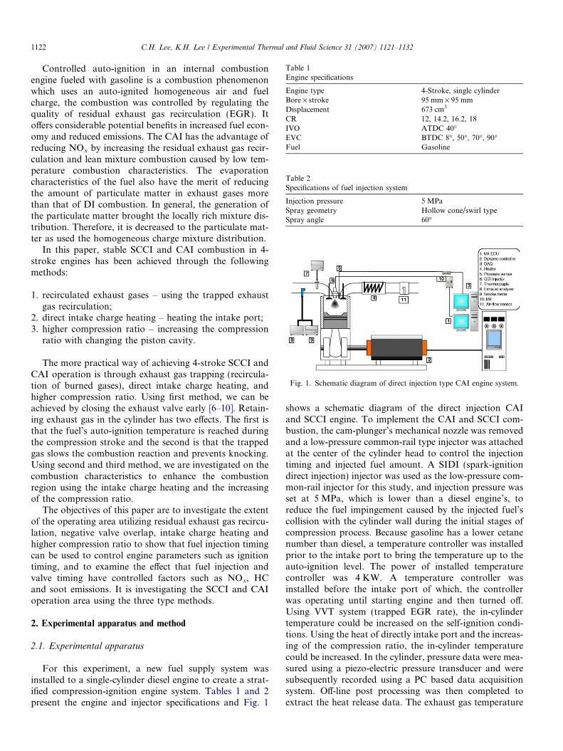
Table 1Engine specifications
Engine type 4-Stroke, single cylinderBore · stroke 95 mm · 95 mmDisplacement 673 cm3
CR 12, 14.2, 16.2, 18IVO ATDC 40�EVC BTDC 8�, 50�, 70�, 90�Fuel Gasoline
Table 2Specifications of fuel injection system
Injection pressure 5 MPaSpray geometry Hollow cone/swirl typeSpray angle 60�
Fig. 1. Schematic diagram of direct injection type CAI engine system.
1122 C.H. Lee, K.H. Lee / Experimental Thermal and Fluid Science 31 (2007) 1121–1132
Controlled auto-ignition in an internal combustionengine fueled with gasoline is a combustion phenomenonwhich uses an auto-ignited homogeneous air and fuelcharge, the combustion was controlled by regulating thequality of residual exhaust gas recirculation (EGR). Itoffers considerable potential benefits in increased fuel econ-omy and reduced emissions. The CAI has the advantage ofreducing NOx by increasing the residual exhaust gas recir-culation and lean mixture combustion caused by low tem-perature combustion characteristics. The evaporationcharacteristics of the fuel also have the merit of reducingthe amount of particulate matter in exhaust gases morethan that of DI combustion. In general, the generation ofthe particulate matter brought the locally rich mixture dis-tribution. Therefore, it is decreased to the particulate mat-ter as used the homogeneous charge mixture distribution.
In this paper, stable SCCI and CAI combustion in 4-stroke engines has been achieved through the followingmethods:
1. recirculated exhaust gases – using the trapped exhaustgas recirculation;
2. direct intake charge heating – heating the intake port;3. higher compression ratio – increasing the compression
ratio with changing the piston cavity.
The more practical way of achieving 4-stroke SCCI andCAI operation is through exhaust gas trapping (recircula-tion of burned gases), direct intake charge heating, andhigher compression ratio. Using first method, we can beachieved by closing the exhaust valve early [6–10]. Retain-ing exhaust gas in the cylinder has two effects. The first isthat the fuel’s auto-ignition temperature is reached duringthe compression stroke and the second is that the trappedgas slows the combustion reaction and prevents knocking.Using second and third method, we are investigated on thecombustion characteristics to enhance the combustionregion using the intake charge heating and the increasingof the compression ratio.
The objectives of this paper are to investigate the extentof the operating area utilizing residual exhaust gas recircu-lation, negative valve overlap, intake charge heating andhigher compression ratio to show that fuel injection timingcan be used to control engine parameters such as ignitiontiming, and to examine the effect that fuel injection andvalve timing have controlled factors such as NOx, HCand soot emissions. It is investigating the SCCI and CAIoperation area using the three type methods.
2. Experimental apparatus and method
2.1. Experimental apparatus
For this experiment, a new fuel supply system wasinstalled to a single-cylinder diesel engine to create a strat-ified compression-ignition engine system. Tables 1 and 2present the engine and injector specifications and Fig. 1
shows a schematic diagram of the direct injection CAIand SCCI engine. To implement the CAI and SCCI com-bustion, the cam-plunger’s mechanical nozzle was removedand a low-pressure common-rail type injector was attachedat the center of the cylinder head to control the injectiontiming and injected fuel amount. A SIDI (spark-ignitiondirect injection) injector was used as the low-pressure com-mon-rail injector for this study, and injection pressure wasset at 5 MPa, which is lower than a diesel engine’s, toreduce the fuel impingement caused by the injected fuel’scollision with the cylinder wall during the initial stages ofcompression process. Because gasoline has a lower cetanenumber than diesel, a temperature controller was installedprior to the intake port to bring the temperature up to theauto-ignition level. The power of installed temperaturecontroller was 4 KW. A temperature controller wasinstalled before the intake port of which, the controllerwas operating until starting engine and then turned off.Using VVT system (trapped EGR rate), the in-cylindertemperature could be increased on the self-ignition condi-tions. Using the heat of directly intake port and the increas-ing of the compression ratio, the in-cylinder temperaturecould be increased. In the cylinder, pressure data were mea-sured using a piezo-electric pressure transducer and weresubsequently recorded using a PC based data acquisitionsystem. Off-line post processing was then completed toextract the heat release data. The exhaust gas temperature
-440 -420 -400 -380 -360 -340 -320 -300 -2800
3
6
9
12
15
18
Rec
om
pre
ssio
n p
ress
ure
(b
ar)
CA (Deg)
EVC 50o
EVC 70o
EVC 90o
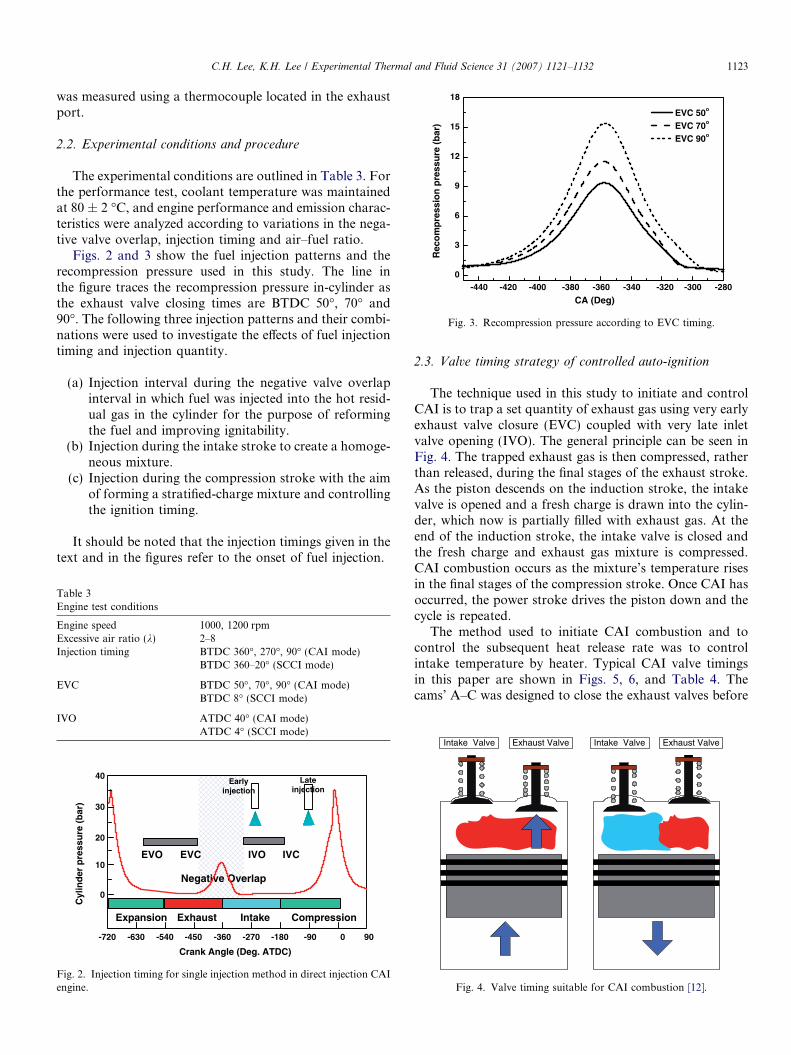
Fig. 3. Recompression pressure according to EVC timing.
C.H. Lee, K.H. Lee / Experimental Thermal and Fluid Science 31 (2007) 1121–1132 1123
was measured using a thermocouple located in the exhaustport.
2.2. Experimental conditions and procedure
The experimental conditions are outlined in Table 3. Forthe performance test, coolant temperature was maintainedat 80 ± 2 �C, and engine performance and emission charac-teristics were analyzed according to variations in the nega-tive valve overlap, injection timing and air–fuel ratio.
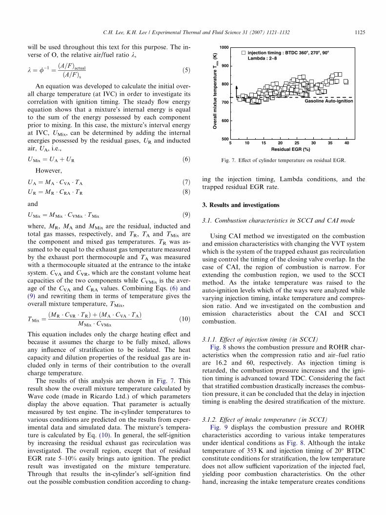
Figs. 2 and 3 show the fuel injection patterns and therecompression pressure used in this study. The line inthe figure traces the recompression pressure in-cylinder asthe exhaust valve closing times are BTDC 50�, 70� and90�. The following three injection patterns and their combi-nations were used to investigate the effects of fuel injectiontiming and injection quantity.
(a) Injection interval during the negative valve overlapinterval in which fuel was injected into the hot resid-ual gas in the cylinder for the purpose of reformingthe fuel and improving ignitability.
(b) Injection during the intake stroke to create a homoge-neous mixture.
(c) Injection during the compression stroke with the aimof forming a stratified-charge mixture and controllingthe ignition timing.
It should be noted that the injection timings given in thetext and in the figures refer to the onset of fuel injection.
Table 3Engine test conditions
Engine speed 1000, 1200 rpmExcessive air ratio (k) 2–8Injection timing BTDC 360�, 270�, 90� (CAI mode)
BTDC 360–20� (SCCI mode)
EVC BTDC 50�, 70�, 90� (CAI mode)BTDC 8� (SCCI mode)
IVO ATDC 40� (CAI mode)ATDC 4� (SCCI mode)
-720 -630 -540 -450 -360 -270 -180 -90 90
Crank Angle (Deg. ATDC)
EVO EVC IVO IVC
Intake CompressionExpansion
Negative Overlap
Exhaust
Cyl
ind
er p
ress
ure
(b
ar)
40
10
20
30
0
Earlyinjection
Lateinjection
0
Fig. 2. Injection timing for single injection method in direct injection CAIengine.
2.3. Valve timing strategy of controlled auto-ignition
The technique used in this study to initiate and controlCAI is to trap a set quantity of exhaust gas using very earlyexhaust valve closure (EVC) coupled with very late inletvalve opening (IVO). The general principle can be seen inFig. 4. The trapped exhaust gas is then compressed, ratherthan released, during the final stages of the exhaust stroke.As the piston descends on the induction stroke, the intakevalve is opened and a fresh charge is drawn into the cylin-der, which now is partially filled with exhaust gas. At theend of the induction stroke, the intake valve is closed andthe fresh charge and exhaust gas mixture is compressed.CAI combustion occurs as the mixture’s temperature risesin the final stages of the compression stroke. Once CAI hasoccurred, the power stroke drives the piston down and thecycle is repeated.
The method used to initiate CAI combustion and tocontrol the subsequent heat release rate was to controlintake temperature by heater. Typical CAI valve timingsin this paper are shown in Figs. 5, 6, and Table 4. Thecams’ A–C was designed to close the exhaust valves before
Intake Valve Exhaust Valve Intake Valve Exhaust Valve
Fig. 4. Valve timing suitable for CAI combustion [12].

IVO(ATDC40o)
EVC(BTDC50o)
IVC(ATDC200o)
EVO(BTDC220o)
EVC(BTDC70o)
IVO(ATDC40o)
IVC(ATDC200o)
EVO(BTDC200o)
EVC(BTDC90o)
IVO(ATDC40o)
IVC
(ATDC200o)EVO
(BTDC180o)
Fig. 5. Valve timings for negative valve overlap.
-300 -250 -200 -150 -100 -50 50 100 150 200 2500
2
4
6
8
10
12
Lif
t (m
m)
CA (Deg)
Standard Valve Lift EVC BTDC 50 EVC BTDC 70 EVC BTDC 90 IVO BTDC 40
0
Fig. 6. Modified valve timing and valve lift.
Table 4Comparison of valve timings between three cam types
Cam A B C
EVC Deg. BTDC 50� BTDC 70� BTDC 90�EVO Deg BTDC 200� BTDC 220� BTDC 180�IVO Deg. ATDC 40� ATDC 40� ATDC 40�IVC Deg ATDC 200� ATDC 200� ATDC 200�
1124 C.H. Lee, K.H. Lee / Experimental Thermal and Fluid Science 31 (2007) 1121–1132
the top dead center (TDC) of the exhaust stroke and toopen the intake valves after TDC of the same stroke. Thisprovided a negative valve overlap (NVO) interval duringwhich, both the exhaust and intake valves were closed.
Since no intake throttling was used in the CAI tests, theengine speed was controlled by a load setting device. Theexhaust valve’s early closure dictates that the intake valve’sopening should be delayed to prevent excessive back-flowof trapped residual gases into the intake manifold.
Three significant phases occur sequentially in the CAIengine’s cycle; namely, residual trapping, residual condi-tioning and CAI combustion. Each phase affects the fol-lowing, with the end-of-cycle conditions feeding back tothe first phase in order to sustain continuous CAI opera-tion. The residual trapping phase is controlled primarilyby the exhaust valve closure’s timing (variable early
EVC) and the trapped residual’s temperature, which couldbe taken as the exhaust gas temperature measured at theexhaust port. Once trapped, the residual’s mass is fixedfor the subsequent cycle, but its temperature and pressureare variable during the residual’s conditioning phase accord-ing to recompression, re-expansion and further heat sub-traction and addition when fuel is injected into theresidual during that period. At the end of the residual’sconditioning phase, which also marks the beginning ofthe intake period (variable late IVO), the released residual’stemperature and pressure will affect the intake air flow, thecharge’s dilution (residuals/total volume) and the combus-tible charge temperature; while fuel injection during theintake period will affect the charge’s homogeneity or strat-ification, leading up to the CAI combustion phase which ischaracterized by CAI ignition timing, heat release rate,IMEP and exhaust emissions. The final exhaust gas tem-perature after CAI is then affected on the next cycle to ini-tiate the next residual trapping phase.
The trapped exhaust gas residual’s mass, mr, at EVCwas estimated using the ideal gas law:
PV ¼ mrRT ; mr ¼PVRT
ð1Þ
The burned gas’ temperature, T(K), at EVC wasassumed to be equal to the temperature measured by athermocouple located in the exhaust port. The in-cylinderpressure at EVC, P, was measured by the in-cylinder pres-sure transducer and the cylinder’s volume at EVC was cal-culated from the engine’s geometry and EVC timing. Theamount of residual at EVC will be the total residual massfor the whole cycle because even if there is a back flow intothe intake ports under some conditions, during steady stateoperation, this gas will subsequently be sucked back intothe cylinder. To make the data more useful, the trappedresidual mass was expressed as a percentage of the totalcharge in the cylinder at IVC,
Residual EGR rate ð%Þ ¼ mr
mfc þ mr
� 100 ð2Þ
where the fresh charge’s mass, mfc, was determined fromthe mass of fuel injected per cycle, mf, and the air–fuel ratio(AFR) as follows. The amount of intake air depends on theamount of the EGR trapped in the cylinder, and measuresby air-flow sensor. The injected fuel was measured and cal-ibrated according to injection interval:
mfc ¼ ðmf �AFRÞ þ mf ð3ÞBecause the composition of the composition products is
significantly different for fuel-lean and fuel-rich mixture,and because the stoichiometric fuel/air depends on fuelcomposition, the ratio of the actual fuel/air ratio to thestochiometric ratio (or its inverse) is a more informativeparameter for defining mixture composition, the fuel/airequivalence ratio /,
/ ¼ ðF =AÞactual
ðF =AÞsð4Þ
5 10 15 20 25 30 35 40500
600
700
800
900
1000
Gasoline Auto-ignition
Ove
rall
mix
tue
tem
per
atu
re T
mix
(K
)
Residual EGR (%)
injection timing : BTDC 360o, 270o, 90o
Lambda : 2~8
Fig. 7. Effect of cylinder temperature on residual EGR.
C.H. Lee, K.H. Lee / Experimental Thermal and Fluid Science 31 (2007) 1121–1132 1125
will be used throughout this text for this purpose. The in-verse of O, the relative air/fuel ratio k,
k ¼ /�1 ¼ ðA=F Þactual
ðA=F Þsð5Þ
An equation was developed to calculate the initial over-all charge temperature (at IVC) in order to investigate itscorrelation with ignition timing. The steady flow energyequation shows that a mixture’s internal energy is equalto the sum of the energy possessed by each componentprior to mixing. In this case, the mixture’s interval energyat IVC, UMix, can be determined by adding the internalenergies possessed by the residual gases, UR and inductedair, UA, i.e.,
U Mix ¼ U A þ UR ð6ÞHowever,
U A ¼ MA � CVA � T A ð7ÞU R ¼ MR � CRA � T R ð8Þ
and
U Mix ¼ MMix � CVMix � T Mix ð9Þwhere, MR, MA and MMix are the residual, inducted andtotal gas masses, respectively, and TR, TA and TMix arethe component and mixed gas temperatures. TR was as-sumed to be equal to the exhaust gas temperature measuredby the exhaust port thermocouple and TA was measuredwith a thermocouple situated at the entrance to the intakesystem. CVA and CVR, which are the constant volume heatcapacities of the two components while CVMix is the aver-age of the CVA and CRA values. Combining Eqs. (6) and(9) and rewriting them in terms of temperature gives theoverall mixture temperature, TMix,
T Mix ¼ðMR � CVR � T RÞ þ ðMA � CVA � T AÞ
MMix � CVMix
ð10Þ
This equation includes only the charge heating effect andbecause it assumes the charge to be fully mixed, allowsany influence of stratification to be isolated. The heatcapacity and dilution properties of the residual gas are in-cluded only in terms of their contribution to the overallcharge temperature.
The results of this analysis are shown in Fig. 7. Thisresult show the overall mixture temperature calculated byWave code (made in Ricardo Ltd.) of which parametersdisplay the above equation. That parameter is actuallymeasured by test engine. The in-cylinder temperatures tovarious conditions are predicted on the results from exper-imental data and simulated data. The mixture’s tempera-ture is calculated by Eq. (10). In general, the self-ignitionby increasing the residual exhaust gas recirculation wasinvestigated. The overall region, except that of residualEGR rate 5–10% easily brings auto ignition. The predictresult was investigated on the mixture temperature.Through that results the in-cylinder’s self-ignition findout the possible combustion condition according to chang-
ing the injection timing, Lambda conditions, and thetrapped residual EGR rate.
3. Results and investigations
3.1. Combustion characteristics in SCCI and CAI mode
Using CAI method we investigated on the combustionand emission characteristics with changing the VVT systemwhich is the system of the trapped exhaust gas recirculationusing control the timing of the closing valve overlap. In thecase of CAI, the region of combustion is narrow. Forextending the combustion region, we used to the SCCImethod. As the intake temperature was raised to theauto-ignition levels which of the ways were analyzed whilevarying injection timing, intake temperature and compres-sion ratio. And we investigated on the combustion andemission characteristics about the CAI and SCCIcombustion.
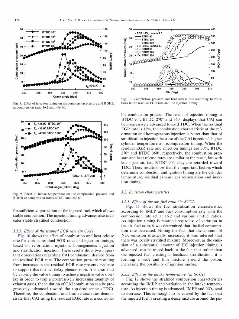
3.1.1. Effect of injection timing (in SCCI)
Fig. 8 shows the combustion pressure and ROHR char-acteristics when the compression ratio and air–fuel ratioare 16.2 and 60, respectively. As injection timing isretarded, the combustion pressure increases and the igni-tion timing is advanced toward TDC. Considering the factthat stratified combustion drastically increases the combus-tion pressure, it can be concluded that the delay in injectiontiming is enabling the desired stratification of the mixture.
3.1.2. Effect of intake temperature (in SCCI)
Fig. 9 displays the combustion pressure and ROHRcharacteristics according to various intake temperaturesunder identical conditions as Fig. 8. Although the intaketemperature of 353 K and injection timing of 20� BTDCconstitute conditions for stratification, the low temperaturedoes not allow sufficient vaporization of the injected fuel,yielding poor combustion characteristics. On the otherhand, increasing the intake temperature creates conditions
340 345 350 355 360 365 370
-10
0
10
20
30
40
50
- EGR 18%, Lamda 4.5 BTDC 90 BTDC 270 BTDC 360
- EGR 30%, Lamda 4.0 BTDC 90 BTDC 270 BTDC 360
CA (Deg)
Co
mb
ust
ion
pre
ssu
re (
bar
)
0
50
100
150
200
250
300
350
400
RO
HR
(J/
Deg
)
Fig. 10. Combustion pressure and heat release rate according to varia-tions in the residual EGR rate and the injection timing.
CR=16, A/F=60
Crank angle [BTDC, deg]350 355 360 365 370 375 380
Co
mb
ust
ion
pre
ssu
re [
bar
]
-10
0
10
20
30
40
50
60
RO
HR
[J/
deg
]
0
20
40
60
80
100
120
140Tin =353K BTDC 20o
Tin =393K BTDC 60o
Tin =433K BTDC 100o
Fig. 9. Effect of intake temperature on the compression pressure andROHR at compression ratios of 16.2 and A/F 60.
Crank angle [deg]350 355 360 365 370 375 380
Co
mb
ust
ion
pre
ssu
re [
bar
]
0
10
20
30
40
50
60
RO
HR
[J/
deg
]
0
20
40
60
80
100
120
140
160BTDC 40o
BTDC 50o
BTDC 60o
BTDC 70o
Tin =393K
Fig. 8. Effect of injection timing on the compression pressure and ROHRat compression ratio 16.2 and A/F 60.
1126 C.H. Lee, K.H. Lee / Experimental Thermal and Fluid Science 31 (2007) 1121–1132
for sufficient vaporization of the injected fuel, which allowsstable combustion. The injection timing advances also indi-cates stable stratified combustion.
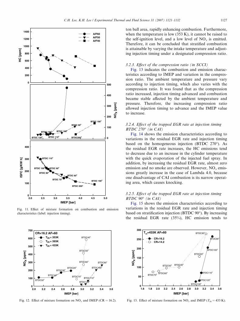
3.1.3. Effect of the trapped EGR rate (in CAI)
Fig. 10 shows the effect of combustion and heat releaserate for various residual EGR rates and injection timings,based on reformation injection, homogeneous injectionand stratification injection. These results show two impor-tant observations regarding CAI combustion derived fromthe residual EGR rate. The combustion pressure resultingfrom increases in the residual EGR rate presents evidenceto support this distinct delay phenomenon. It is clear thatby varying the valve timing to achieve negative valve over-lap in order to trap a progressively increasing quantity ofexhaust gases, the initiation of CAI combustion can be pro-gressively advanced toward the top-dead-center (TDC).Therefore, the combustion and heat release rates demon-strate that CAI using the residual EGR rate is a controlla-
ble combustion process. The result of injection timing atBTDC 90�, BTDC 270� and 360� displays that CAI canbe progressively advanced toward TDC. When the residualEGR rate is 18%, the combustion characteristic at the ref-ormation and homogeneous injection is better than that ofstratification injection because of the CAI injection’s highercylinder temperature at recompression timing. When theresidual EGR rate and injection timings are 30%, BTDC270� and BTDC 360�, respectively, the combustion pres-sure and heat release rates are similar to the result, but withlate injection, i.e., BTDC 90�, they are retarded towardTDC. These results show that the important factors whichdetermine combustion and ignition timing are the cylindertemperature, residual exhaust gas recirculation and injec-tion timing.
3.2. Emission characteristics
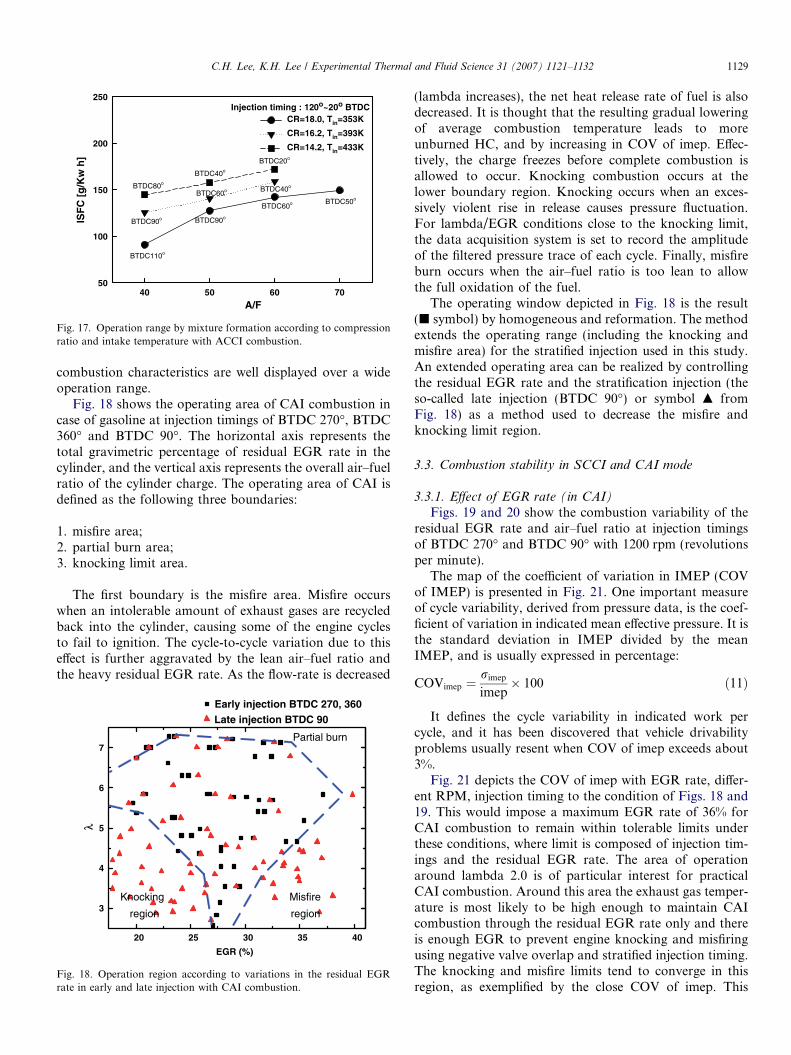
3.2.1. Effect of the air–fuel ratio (in SCCI)Fig. 11 shows the fuel stratification characteristics
according to IMEP and fuel consumption rate with thecompression rate set at 16.2 and various air–fuel ratios.As injection timing is retarded regardless of variation inthe air–fuel ratio, it was determined that the fuel consump-tion rate decreased. Noting the fact that the amount ofNOx emission drastically increased, it was inferred thatthere was locally stratified mixture. Moreover, as the emis-sion of a substantial amount of HC injection timing isadvanced, can be traced back to the fact that rather thanthe injected fuel creating a localized stratification, it isforming a wide and thin mixture around the piston,increasing the possibility of ignition misfire.
3.2.2. Effect of the intake temperature (in SCCI)
Fig. 12 shows the stratified combustion characteristicsaccording the IMEP and variation in the intake tempera-ture. As injection timing is advanced, IMEP and NOx tendto decrease. This is thought to be caused by the fact thatthe injected fuel is creating a dense mixture around the pis-
IMEP [bar]2.0 2.5 3.0 3.5 4.0 4.5 5.0
ISF
C [
g/K
W h
]
0
100
200
300
400
0
100
200
300
400
500
HC
[p
pm
]
0
200
400
600
800
1000
1200
1400A/F60A/F50A/F40
BTDC 110
BTDC 100 BTDC 90
BTDC 80
BTDC 70
BTDC 60
BTDC 90
BTDC 100
BTDC 110
BTDC 120
BTDC 130 BTDC200
BTDC 190
BTDC 200
BTDC 190
NO
x [p
pm
]
Fig. 11. Effect of mixture formation on combustion and emissioncharacteristics (label: injection timing).
CR=16.2 AF=60
IMEP [bar]
2.0 2.2 2.4 2.6 2.8 3.0 3.2 3.4 3.6
NO
x [p
pm
]
0
100
200
300
400
500
600
700
Tin = 353K
Tin = 393K
Tin = 433K
BTDC20BTDC30
BTDC40
BTDC50
BTDC40
BTDC50
BTDC60
BTDC70
BTDC90
BTDC100
BTDC110
BTDC120
Fig. 12. Effect of mixture formation on NOx and IMEP (CR = 16.2).
C.H. Lee, K.H. Lee / Experimental Thermal and Fluid Science 31 (2007) 1121–1132 1127
ton ball area, rapidly enhancing combustion. Furthermore,when the temperature is low (353 K), it cannot be raised tothe self-ignition level, and a low level of NOx is emitted.Therefore, it can be concluded that stratified combustionis attainable by varying the intake temperature and adjust-ing injection timing under a designated compression ratio.
3.2.3. Effect of the compression ratio (in SCCI)
Fig. 13 indicates the combustion and emission charac-teristics according to IMEP and variation in the compres-sion ratio. The ambient temperature and pressure varyaccording to injection timing, which also varies with thecompression ratio. It was found that as the compressionratio increased, injection timing advanced and combustionbecame stable affected by the ambient temperature andpressure. Therefore, the increasing compression ratioallowed injection timing to advance and the IMEP valueto increase.
3.2.4. Effect of the trapped EGR rate at injection timing
BTDC 270� (in CAI)Fig. 14 shows the emission characteristics according to
variations in the residual EGR rate and injection timingbased on the homogeneous injection (BTDC 270�). Asthe residual EGR rate increases, the HC emissions tendto decrease due to an increase in the cylinder temperaturewith the quick evaporation of the injected fuel spray. Inaddition, by increasing the residual EGR rate, almost zeroemission and no smoke are observed. However, NOx emis-sions greatly increase in the case of Lambda 4.0, becauseone disadvantage of CAI combustion is its narrow operat-ing area, which causes knocking.
3.2.5. Effect of the trapped EGR rate at injection timing
BTDC 90� (in CAI)
Fig. 15 shows the emission characteristics according tovariations in the residual EGR rate and injection timingbased on stratification injection (BTDC 90�). By increasingthe residual EGR rate (35%), HC emission tends to
Tin=433K AF=60
IMEP [bar]
1.6 1.8 2.0 2.2 2.4 2.6 2.8 3.0 3.2 3.4 3.6
NO
x [p
pm
]
0
50
100
150
200
250
300
CR=16.2CR=14.2
BTDC20
BTDC30
BTDC40BTDC50
BTDC60BTDC70
BTDC90
BTDC100
BTDC110
BTDC120
BTDC130
Fig. 13. Effect of mixture formation on NOx and IMEP (Tin = 433 K).

4.0 4.5 5.0 5.5 6.0
0
100
200
300
400
500
600
700 Injection timing BTDC 270o
NO
x an
d H
C e
mis
sio
n (
pp
m)
Lamda
HC, EGR 25% NOx, EGR 25% HC, EGR 30% NOx, EGR 30% HC, EGR 35% NOx, EGR 35%
Fig. 14. Emission characteristics according to variations in the residualEGR rate at injection timing BTDC 270�.
2.5 3.0 3.5 4.0 4.5 5.0 5.5 6.0 6.50
200
400
600
800
1000
1200
1400Injection Timing 90o
HC, EGR 17% NOx, EGR 17% HC, EGR 23% NOx, EGR 23% HC, EGR 31% NOx, EGR 31%
Lambda
NO
x an
d H
C e
mis
sio
n [
pp
m]
3.0 3.5 4.0 4.5 5.0 5.5 6.0-1
0
1
2
3
4
5
6
Sm
oke
[%
]
Lambda
EGR 17% EGR 23% EGR 31%
a
b
Fig. 15. Emission characteristics according to variations in the residualEGR at injection timing BTDC 90�: (a) NOx and HC (b) Soot.
390 360 330 300 270 240 210 180 150 120 90 60
0
200
400
600
800
1000
NO
x an
d H
C e
mis
sio
n (
pp
m)
Injection timing (BTDC, CA)
HC, EGR 20% NOx, EGR 20% HC, EGR 25% NOx, EGR 25% HC, EGR 33% NOx, EGR 33%
Fig. 16. Emission characteristics according to variations in injectiontiming at an engine speed of 1200 rpm.
1128 C.H. Lee, K.H. Lee / Experimental Thermal and Fluid Science 31 (2007) 1121–1132
decrease, the same as the result in Fig. 14. On the otherhand, more NOx was emitted than in Fig. 14. Increasingthe residual exhaust gas recirculation shows a decrease inNOx emissions. The reason that NOx emissions increasehere, different from early injection, is that the rich mixtureis concentrated in the local area. Therefore, NOx emissions
are reduced by increasing the air/fuel ratio. On the otherhand, early injection based on homogeneous injection doesnot cause smoke but late injection based on stratificationdoes bring a small quantity of smoke. The reason for thisis because air leaked into the rich mixture that increasedthe residual EGR rate.
3.2.6. Effect of the injection timing (in CAI)
Fig. 16 shows emission characteristics at 1200 rpmaccording to variations in the residual EGR rate and injec-tion timing. The emission of HC rapidly decreases as theresidual EGR rate increases regardless of injection timing,because fuel evaporation is promoted by increasing the cyl-inder temperature up to the auto-ignition temperature.This result shows that, regardless of variations in the resid-ual EGR rate, injection timings at BTDC 270�and BTDC360� do not increase NOx emissions, but late injection sig-nificantly reduces NOx emissions, as it does the residualEGR rate (31%). That reason is, while the in-cylinder tem-perature increases due to increase the trapped residual gas,the combustion temperature decrease due to increase theinactive gas.
3.2.7. Operating region to SCCI and CAI mode
Fig. 17 shows the operation range characteristicsaccording to the compression ratio and intake temperatureacquired from results in Figs. 8 and 9. Kaneko [7] claimedthat the operation range where a uniform mixture can becreated is around AF 35–40. The results of this studyrevealed that if the stratified mixture is formed, the air–fuelratio yields operating characteristics in a wider range com-pared to a uniform mixture. Even at a leaner air–fuel ratiocompared to the operation range that forms a uniform mix-ture, it was found that combustion became stable when astratified mixture was generated. As for the operationrange according to variation in the intake temperature,although the fuel consumption rate is disadvantageouscompared to cases with high compression ratios, stratified
A/F40 50 60 70
ISF
C [
g/K
w h
]
50
100
150
200
250
CR=18.0, Tin=353K
CR=16.2, Tin=393K
CR=14.2, Tin=433K
Injection timing : 120o~20o BTDC
BTDC50BTDC60
BTDC90
BTDC110
BTDC40BTDC60
BTDC90
BTDC20
BTDC40
BTDC80
Fig. 17. Operation range by mixture formation according to compressionratio and intake temperature with ACCI combustion.
C.H. Lee, K.H. Lee / Experimental Thermal and Fluid Science 31 (2007) 1121–1132 1129
combustion characteristics are well displayed over a wideoperation range.
Fig. 18 shows the operating area of CAI combustion incase of gasoline at injection timings of BTDC 270�, BTDC360� and BTDC 90�. The horizontal axis represents thetotal gravimetric percentage of residual EGR rate in thecylinder, and the vertical axis represents the overall air–fuelratio of the cylinder charge. The operating area of CAI isdefined as the following three boundaries:
1. misfire area;2. partial burn area;3. knocking limit area.
The first boundary is the misfire area. Misfire occurswhen an intolerable amount of exhaust gases are recycledback into the cylinder, causing some of the engine cyclesto fail to ignition. The cycle-to-cycle variation due to thiseffect is further aggravated by the lean air–fuel ratio andthe heavy residual EGR rate. As the flow-rate is decreased
20 25 30 35 40
3
4
5
6
7
Early injection BTDC 270, 360Late injection BTDC 90
EGR (%)
Knocking
region
Misfire
region
Partial burn
λ
Fig. 18. Operation region according to variations in the residual EGRrate in early and late injection with CAI combustion.
(lambda increases), the net heat release rate of fuel is alsodecreased. It is thought that the resulting gradual loweringof average combustion temperature leads to moreunburned HC, and by increasing in COV of imep. Effec-tively, the charge freezes before complete combustion isallowed to occur. Knocking combustion occurs at thelower boundary region. Knocking occurs when an exces-sively violent rise in release causes pressure fluctuation.For lambda/EGR conditions close to the knocking limit,the data acquisition system is set to record the amplitudeof the filtered pressure trace of each cycle. Finally, misfireburn occurs when the air–fuel ratio is too lean to allowthe full oxidation of the fuel.
The operating window depicted in Fig. 18 is the result(j symbol) by homogeneous and reformation. The methodextends the operating range (including the knocking andmisfire area) for the stratified injection used in this study.An extended operating area can be realized by controllingthe residual EGR rate and the stratification injection (theso-called late injection (BTDC 90�) or symbol m fromFig. 18) as a method used to decrease the misfire andknocking limit region.
3.3. Combustion stability in SCCI and CAI mode
3.3.1. Effect of EGR rate (in CAI)
Figs. 19 and 20 show the combustion variability of theresidual EGR rate and air–fuel ratio at injection timingsof BTDC 270� and BTDC 90� with 1200 rpm (revolutionsper minute).
The map of the coefficient of variation in IMEP (COVof IMEP) is presented in Fig. 21. One important measureof cycle variability, derived from pressure data, is the coef-ficient of variation in indicated mean effective pressure. It isthe standard deviation in IMEP divided by the meanIMEP, and is usually expressed in percentage:
COVimep ¼rimep
imep� 100 ð11Þ
It defines the cycle variability in indicated work percycle, and it has been discovered that vehicle drivabilityproblems usually resent when COV of imep exceeds about3%.
Fig. 21 depicts the COV of imep with EGR rate, differ-ent RPM, injection timing to the condition of Figs. 18 and19. This would impose a maximum EGR rate of 36% forCAI combustion to remain within tolerable limits underthese conditions, where limit is composed of injection tim-ings and the residual EGR rate. The area of operationaround lambda 2.0 is of particular interest for practicalCAI combustion. Around this area the exhaust gas temper-ature is most likely to be high enough to maintain CAIcombustion through the residual EGR rate only and thereis enough EGR to prevent engine knocking and misfiringusing negative valve overlap and stratified injection timing.The knocking and misfire limits tend to converge in thisregion, as exemplified by the close COV of imep. This

Fig. 19. Diagram of combustion stability according to the variation ofresidual EGR rate: (a) early injection and (b) late injection.
Fig. 20. Diagram of combustion stability according to the variation of theair–fuel ratio: (a) early injection and (b) late injection.
5 1000 rpm 1200 rpm
1130 C.H. Lee, K.H. Lee / Experimental Thermal and Fluid Science 31 (2007) 1121–1132
may be achieved by maintaining self-ignition to use theresidual EGR rate or exhaust valve overlap and injectiontimings.
15 20 25 30 35-1
0
1
2
3
4
CO
V o
f IM
EP
(%
)
EGR (%)
Fig. 21. Combustion stability with the residual EGR rate and engine rpm.
3.3.2. Stability on the intake temperature and compression
ratio (in SCCI)
Fig. 22 indicates combustion stability according to var-ious compression ratios, injection timings and intake tem-peratures. Fig. 22a indicates combustion stabilityaccording to various air–fuel ratios at the intake tempera-ture of 353 K. It can be noted that as injection timing isadvanced, combustion stability decreases. This is thoughtto be caused by the fact that as injection timing isadvanced, rather than the injected fuel remaining withinthe combustion chamber, there is an increasing amountof mixture on the cylinder wall and outside the combustionchamber. As injection timing is delayed toward the TDC, itbecomes easier for the fuel to stratify at the center of thecombustion chamber and it increases combustion stability.The decrease in the compression ratio causes the increase inthe probability of ignition misfire and therefore the
decrease in the stability. When the air–fuel ratio becomesdense, the area of stable combustion is advanced accordingto the effects of injection timing. Fig. 22b displays combus-

Injection timing [BTDC, Deg]
020406080100120140
CO
V o
f IM
EP
[%
]
0
2
4
6
8
10
12CR=18 AF=70CR=18 AF=60CR=18 AF=50CR=16.2 AF=60CR=16.2 AF=50CR=16.2 AF=40
Tin = 353K
Injection timing [CA, Deg]20406080
CO
V o
f IM
EP
[%
]
0
2
4
6
AF=60 T393K AF=50 T393KAF=40 T393KAF=60 T433KAF=50 T433KAF=40 T433K
Fig. 22. Combustion stability according to effect of compression ratio andinjection timing: (a) in the case where intake temperature Tin = 353 K and(b) in the case where compression ratio = 14.2.
C.H. Lee, K.H. Lee / Experimental Thermal and Fluid Science 31 (2007) 1121–1132 1131
tion stability according to the intake temperature with thecompression ratio at 14.2. The results in Fig. 22b indicatedthat combustion stability increases as injection timing isadvanced. It was confirmed that combustion was unstableat 393 K compared to 433 K. When the intake air was setat 433 K, it expedited fuel evaporation, improving combus-tion performance and displaying somewhat stable combus-tion characteristics.
4. Conclusions
Gasoline CAI combustion using residual exhaust gasrecirculation has been achieved. Measurements of variouscombustion characteristics and emissions within this regionhave led to the following conclusions:
CAI combustion mode
1. The operating region has three main boundaries: (i)partial burn limit, where combustion temperature isnot high enough to allow complete combustion atlean air–fuel ratios, (ii) misfire limit, where concentra-tions are high enough to cause extremely retardedignition and long combustion duration, and (iii)knocking limit, where heat release rates are highenough to cause pressure oscillations in the cylinder.
2. The cylinder temperature according to the residualEGR rate is reached the auto-ignition temperatureof the gasoline. The small region of the residualEGR rate (EGR rate is about 5–10%) does not reachthe auto-ignition temperature and increases HCemissions.
3. The mixture cylinder temperature and residual EGRrate are important factors affecting the combustioncharacteristics and ignition timings. Early injectionbased on the reformation and homogeneous injectiondoes not cause smoke but late injection based onstratification injection causes smoke.
4. The highest IMEP is 5 bar at lambda 5.0, EGR rate28% and the so-called cam type C, or EVC 90�, whereall exhaust emissions are at a minimum except HC. Inaddition, COV imep trends stabilize with the air–fuelratio and the residual EGR rate.
5. Unburned HC emissions are reduced by increasingthe mixture cylinder temperature according toincreases in the residual EGR rate. This is why theinjected fuel quickly evaporated.
SCCI combustion mode
The combustion characteristics according to variation ininjection timing revealed that as injection timing isadvanced, ignition timing is delayed and combustionpressure is decreased.1. Combustion and emission characteristics according
to variation in the compression ratio revealed thatas the compression ratio increased, injection timingis delayed and the IMEP value increased.
2. As the compression ratio increased, injection timingadvanced and combustion became stable affected bythe ambient temperature and pressure.
3. In cases where a stratified mixture was formedaccording to variations in the intake temperature,compression ratio and injection timing, the air–fuelratio (AF40–70) displays combustion characteristicsin a wider operation range compared to that of a uni-form mixture.
4. Increasing the intake temperature creates conditionsfor sufficient vaporization of the injected fuel, whichallows stable combustion. The injection timing andinduced air temperature play a role of importantparameter for stable stratified combustion.
Acknowledgement
This work was supported by the research fund of CERCand we would like to show appreciation to its associatedorganizations.
References
[1] T. Aoyama, Y. Hattori, An Experimental Study on Premixed –Charge Compression Ignition Gasoline Engine, SAE 960081, 1996.
[2] Y. Ishibashi et al., A Low Pressure Pneumatic Two-stroke Engine byActivated Radical Combustion Concepts, SAE 980757, 1998.
1132 C.H. Lee, K.H. Lee / Experimental Thermal and Fluid Science 31 (2007) 1121–1132
[3] L. Jacques, et al., Innovative Ultra-low NOx Controlled Auto-ignition Combustion Process for Gasoline Engine, SAE 2000-01-1837, 2000.
[4] Morikawa, et al., First Report Concerning Research on a Premixed-charge Compression Ignition Gasoline Engine, SAE Paper 2001Spring Congress of JSAE No. 51-01, 2001, pp. 5–8.
[5] Tomonori Urushihara, Koji Hiraya, Akihiko Kakuhou, TeruyukiItoh, Expansion of HCCI Operating Area by the Combination ofDirect Fuel Injection, Negative Valve Overlap and Internal FuelReformation, SAE 2003-01-0749, 2003.
[6] Koji Hiraya, Kazuya Hasegawa, Tomonori Urushihara, AkihiroIiyama, Teruyuki Itoh, A Study on Gasoline Fueled CompressionIgnition Engine – A Trial of Operation Region Expansion, SAE 2002-01-0416, 2002.
[7] M. Kaneko et al., Study on homogeneous charge compressionignition gasoline engine, COMODIA (2001) 441–446.
[8] Lee Kihyung et al., An experimental study on the two-stage ignitionof cool flame and hot flame in HCCI engine according to fuelcompression, Transactions of KASE 12 (1) (2004) 17–24.
[9] Richard Standing, Tom Ma, Hua Zhao, Effect of Injection Timingand Valve Timings on CAI Operation in a Multi-cylinder DI GasolineEngine, SAE 2005-01-0132, 2005.
[10] B. Thirouard, V. Knop, Investigation of Mixture Quality Effect onCAI Combustion, SAE 2005-01-0141, 2005.
[11] Aron Oakley, Hue Zhao, Nicos Lasommatos, Experimental Study onControlled Auto- ignition Combustion of Gasoline in a 4-strokeEngine, SAE 2001-01-1030, 2001.
[12] Don Law, Jeff Allen, On the Mechanism of Controlled auto Ignition,2002-01-0412, 2002.
[13] Rui Chen, Nebojsa Milovanovic, The Thermal Effect of InternalExhaust Gas Recirculation on Controlled Auto Ignition, SAE 2003-01-0751, 2003.
[14] Yoon Younghoon, Kim Daesik, Lee Changsik, Effect of premixed fueland EGR on the combustion and emission characteristics of HCCIdiesel engine, Transaction of KSME B 29 (9) (2005) 1006–1012.
[15] Kyunghwan Lee, Gopalakrishnan Venkatesh, John Abraham, Aninvestigation of the effect of changes in engine operating conditionson ignition in an HCCI engine, KSME International Journal 18 (10)(2004) 1809–1818.
[16] J. Lavy, J. Dabadie, C. Angelberger, P. Duret, (IFP), J. Willand,A. Juretzka, J. Schafein, (Daimler-Chrysler), T. Ma, (Ford), Y.Lendresse, A. Satre, (PSA Peugeot Citroen), C. Schulz, H. Kramer,(PCI –Heidelburg University), H. Zhao, L. Damiano, (BrunelUniversity), Innovative Ultra-low NOx Controlled Auto-ignitionCombustion Process for Gasoline Engine: The 4-SPACE Project,SAE Paper 2000-01-1837, 2000.
[17] D. Law, J. Allen, D. Kemp, P. Williams, 4-Stroke Active Combustion(Controlled Auto-Ignition) Investigation using a Single CylinderEngine with Lotus Active Valve Train (AVT), in: Proceedings of theInternational Conference on 21st Century Emissions Technology,C588/006/2000, IMechE, 2000.
[18] J. Li, H. Zhao, T. Ma, N. Ladommatos, Research and Developmentof Controlled Auto-Ignition (CAI) combustion in a 4-Stroke Multi-cylinder Gasoline Engine, SAE Paper 2001-01-3608, 2001.
![[Scci'16] [Markative] Session 1 - Introduction to graphic design](https://static.fdocuments.us/doc/165x107/5871c3061a28ab55058b70b5/scci16-markative-session-1-introduction-to-graphic-design.jpg)


![SCCI'14 - appsplash[4] : Design!](https://static.fdocuments.us/doc/165x107/554d3075b4c905ca208b56ca/scci14-appsplash4-design.jpg)

![SCCI'14 - Appsplash [3] Planning, Researching and Deciding!](https://static.fdocuments.us/doc/165x107/554d316ab4c905ab268b5427/scci14-appsplash-3-planning-researching-and-deciding.jpg)