Amphenol AIB/GT Series MIL-DTL-5015 - Farnell element14 · The standard MIL-DTL-5015 layouts and...
58
65 5015 - AMPHENOL AIB/GT SERIES MIL-DTL-5015 For assistance in Europe, please see the back cover for a complete listing of our branch offices and contact numbers. Specifications subject to change. APPLICATIONS AIB/GT series connectors are made in accordance with German military specification VG95234 and MIL-DTL-5015. Originally designed for NATO combat vehicles, aircraft, and airborne equipment, these rugged connectors are now in a broad range of demanding commercial applications from trucks to industrial robots. • Power generators • Battery systems • Engines • Sensors • Motion control • Off-road vehicles • Earth-moving equipment • Ships • Railroad equipment • Mobile equipment • Industrial machinery • Telecommunications • Mass transit Industrial environments requiring extreme environmental reliability and ease of mating and unmating, such as: SIMPLE AND FAST MATING AND UN-MATING AIB/GT series connectors use a unique “reverse bayonet” coupling system that allows for mating and un-mating with a simple 120˚ rotation without compromising shock, vibration, or moisture resistance. The large, open ramps are easily cleaned of mud or other contaminants. The ramp coupling system eliminates the possibility of cross-threading and thread damage possible with standard MIL-DTL-5015 threaded connectors. This design is easier to mate in cold weather, tight spaces, or on equipment which must be disassembled frequently. SHOCK AND VIBRATION RESISTANCE AIB/GT series connectors are supplied with military-standard resistant sealing and a three-point bayonet coupling nut. The three-point bayonet coupling incorporates a wave spring and washer specified by the rail industry. AIB/GT series connectors pass the most stringent tests of shock and vibration performance while maintaining proper continuity and water tightness. Rugged aluminum alloy shell and hardware are light in weight yet highly resistant to damage. Amphenol AIB/GT Series MIL-DTL-5015 IMPROVED COUPLING OVER THREADED MIL-DTL-5015 The AIB/GT Series replaces the threaded coupling used in MIL-DTL-5015 with a positive, quick-mating, three-point reverse bayonet lock for improved performance. These Amphenol connectors are an ideal cost-effective option for applications requiring reliability in harsh environments, and is the world- standard for rail, mass transit, and military ground vehicle applications. This series has the same shell dimensions, contact layouts, contacts, and performance characteristics as the MIL-DTL-5015 threaded connectors; however, the two series do not intermate. They are sealed to withstand moisture, condensation, vibration and flash-over. Over 180 contact layouts are available, in variations that allow for just power, just signal, or a mix of both contact types. • Meets NATO specification VG95234 COMMERCIAL & MILITARY FEATURES
Transcript of Amphenol AIB/GT Series MIL-DTL-5015 - Farnell element14 · The standard MIL-DTL-5015 layouts and...

65
5015 - AMPH
ENO
L AIB/GT SERIES M
IL-DTL-5015
For assistance in Europe, please see the back cover for a complete listing of our branch offices and contact numbers.Specifications subject to change.
APPLICATIONS
AIB/GT series connectors are made in accordance with German military specification VG95234 and MIL-DTL-5015. Originally designed for NATO combat vehicles, aircraft, and airborne equipment, these rugged connectors are now in a broad range of demanding commercial applications from trucks to industrial robots.
• Power generators
• Battery systems
• Engines
• Sensors
• Motion control
• Off-road vehicles
• Earth-moving equipment
• Ships
• Railroad equipment
• Mobile equipment
• Industrial machinery
• Telecommunications
• Mass transit
Industrial environments requiring extreme environmental reliability and ease of mating and unmating, such as:
SIMPLE AND FAST MATING AND UN-MATING
AIB/GT series connectors use a unique “reverse bayonet” coupling system that allows for mating and un-mating with a simple 120˚ rotation without compromising shock, vibration, or moisture resistance. The large, open ramps are easily cleaned of mud or other contaminants. The ramp coupling system eliminates the possibility of cross-threading and thread damage possible with standard MIL-DTL-5015 threaded connectors. This design is easier to mate in cold weather, tight spaces, or on equipment which must be disassembled frequently.
SHOCK AND VIBRATION RESISTANCE
AIB/GT series connectors are supplied with military-standard resistant sealing and a three-point bayonet coupling nut. The three-point bayonet coupling incorporates a wave spring and washer specified by the rail industry. AIB/GT series connectors pass the most stringent tests of shock and vibration performance while maintaining proper continuity and water tightness. Rugged aluminum alloy shell and hardware are light in weight yet highly resistant to damage.
Amphenol AIB/GT Series MIL-DTL-5015IMPROVED COUPLING OVER THREADED MIL-DTL-5015The AIB/GT Series replaces the threaded coupling used in MIL-DTL-5015 with a positive, quick-mating, three-point reverse bayonet lock for improved performance. These Amphenol connectors are an ideal cost-effective option for applications requiring reliability in harsh environments, and is the world-standard for rail, mass transit, and military ground vehicle applications. This series has the same shell dimensions, contact layouts, contacts, and performance characteristics as the MIL-DTL-5015 threaded connectors; however, the two series do not intermate. They are sealed to withstand moisture, condensation, vibration and flash-over. Over 180 contact layouts are available, in variations that allow for just power, just signal, or a mix of both contact types.
• Meets NATO specification VG95234
COMMERCIAL & MILITARY
FEATURES

66
5015 - AMPH
ENO
L AIB/GT SERIES M
IL-DTL-5015
For assistance in North America: +1 800.642.8750 for Pricing/Delivery or +1 800.523.0727 Tech Support • www.peigenesis.com • [email protected]
AUDIBLE, VISUAL, AND TACTILE CONFIRMATION OF MATING
AIB/GT series connectors provide three independent checks that the connector halves are mated. When the coupling nut is fully rotated, the three studs snap into the end of the ramps with a loud “click” (audible). The user can feel the bolts click into the grooves (tactile). Blue dots on the receptacle and coupling nut are aligned when the connector is properly mated (visual).
ENVIRONMENTAL
The sealing is not compromised by any of the operating conditions defined in MIL-DTL-5015 and is completely watertight when mated.
BROAD TEMPERATURE RANGE
These connectors will operate in temperatures from -67˚ to +257˚F (-55˚ to +125˚C). High-temperature and zero-halogen insulators are also available. Contact us for ordering information.
WIDE RANGE OF WIRE GAUGES AND CURRENT-CARRYING CAPABILITY
Up to 150 amps with accommodations for wire gauges from size 26 to size 0 AWG.
WIDE VARIETY OF CONTACTS
High-reliability screw machine contacts with silver or gold plating are available in sizes from 20 to 0 to accommodate wire gauges from 26 to 0 AWG. Solder, crimp, PC, coax, and thermocouple contacts are available.
AIB/GT connectors use rail industry-standard crimp contacts that are completely interchangeable with other rail connectors such as Litton/Veam CIR series.
INTERMATEABLE AND INTERMOUNTABLE WITH ALL VG95234 CONNECTORS
The standard MIL-DTL-5015 layouts and dimensions ensure intermateability and intermount ability with all connectors made in accordance with VG95234.
All AIB/GT connectors are intermountable with standard threaded MIL-DTL-5015 connectors, often making it possible to upgrade without changing panel cutouts or clearances.
MATERIALS & FINISHESShell Aluminum alloy. (Can be grounded)
Plating Olive drab chromate coating over cadmium plating, conductive black alloy, black alloy, electroless nickel, green zinc, and black anodized
Contacts Copper alloy
Platings Hard silver plating or gold plating
Insulator* Neoprene
Seals Silicone, Neoprene, or Viton®**
*Optional zero-halogen and high-temperature insulators are available. Contact us for information.**Viton® is a registered trademark of DuPont DOW Elastomers
FEATURES
TECHNICAL SPECIFICATIONS

67
5015 - AMPH
ENO
L AIB/GT SERIES M
IL-DTL-5015
For assistance in Europe, please see the back cover for a complete listing of our branch offices and contact numbers.Specifications subject to change.
CONTACT SIZE TEST CURRENT (AMPS) 16/16S 13 12 23 (60)* 8 46 (69)* 4 80 (120)* 0 150 (225)*
ELECTRICAL DATAOperating Voltage/Test Voltage according to MIL-DTL-5015H The indicated values for the operating voltage are limits concerning the electrical function. When the working voltage exceeds 50V, safety precautions must be in accordance with the following standards: VDE 0100, IEC 309-1 or applicable national standards.
Current Rating
Altitude Voltage Derating* Chart
per MIL-DTL-5015H p 3.15
CONTACT CONTACT RESISTANCE POTENTIAL VOLTAGE SIZE MILLIOHM MAX. DROP IN MILLIVOLTS MAX. 16/16S 6 21 12 3 20 8 1/(0.44)* 12 (20)* 4 0.5/(0.23)* 10 (18)* 0 0.2/(0.18)* 10 (27)*
Insulation Resistance @77˚F (25˚C) > 5,000 Megohms
MECHANICALOperating Temperature -67˚ to +257˚F (-55˚ to +125˚C) Neoprene
Sealing 33-foot submersible Sealed when mated. ≈ IP 67 and NEMA 4P
* No attempt has been made to recommend operating voltages. The designer must determine own operating voltage by the application of a safety factor to the above derating chart to compensate for circuit transients, surges, etc.
† Not corrected for changes in density due to variations in temperature.
Wire Range Sizes 26 AWG to 0 AWG (See contact selection on apages 94-97)
Contact Resistance
I 1/32 1/16 250 200 1,400 1,000 550 400 325 260 A 1/16 1/8 700 500 2,800 2,000 800 600 450 360 D 1/8 3/16 1,250 900 3,600 2,800 900 675 500 400 E 3/16 1/4 1,750 1,250 4,500 3,500 1,000 750 550 440 B 1/4 5/16 2,450 1,750 5,700 4,500 1,100 825 600 480 C 5/16 1 4,200 3,000 8,500 7,000 1,300 975 700 560
*Using Radsok contact
*Test amps, multiconductor using Radsok contact
TECHNICAL SPECIFICATIONS
NOMINAL DISTANCE
STANDARD SEA LEVEL
CONDITIONS
PRESSURE ALTITUDE† 50,000 FEET
PRESSURE ALTITUDE† 70,000 FEET
OPERATING VOLTAGE*
MSSERVICERATING
AIRSPACE CREEPAGE DC V AC VRMS
MINIMUMFLASHOVER
VOLTAGEAC (RMS)
TESTVOLTAGEAC (RMS)
MINIMUMFLASHOVER
VOLTAGEAC (RMS)
TESTVOLTAGEAC (RMS)
MINIMUMFLASHOVER
VOLTAGEAC (RMS)
TESTVOLTAGEAC (RMS)

68
5015 - AMPH
ENO
L AIB/GT SERIES M
IL-DTL-5015
For assistance in North America: +1 800.642.8750 for Pricing/Delivery or +1 800.523.0727 Tech Support • www.peigenesis.com • [email protected]
SEALING RANGE
16 .064 - .130 1.62 - 3.30 12 .114 - .170 2.89 - 4.31 8 .164 - .255 4.16 - 6.47 4 .272 - .370 6.90 - 9.30 0 .415 - .550 10.50 - 13.97
CONTACT SIZE
Wire Sealing Range The connector is designed for individual wire sealing. Sealing of an outer cable jacket on multiconductor cables must be accomplished with an appropriate endbell. Sealing is only guaranteed if wires used are according to MIL-W-5086 or within the listed ranges.
INCHES MM
Insulation Strip Lengths See Contact Selection Chart on apages 94 and 97
Mating Life 2,000 cycles minimum (AIB/GT) 500 cycles minimum (AIBC/ACA-B)
Salt Spray Olive drab chromate over cadmium - 500 hours Black alloy - 48 to 200 hours Conductive black alloy - 48 to 200 hours Black anodized - 500+ hours Electroless nickel - 48 hours
Heat Neoprene low-smoke, zero-halogen (LSZH) 257˚F (+125˚C); Viton 392˚F (+200˚C)
Chemical Resistance Diesel Fuel 48-hour intermittent spray for each JP-4 chemical with no deterioration, Hydraulic Fluid followed by Contact Retention (CR), Gasoline Insulation Resistance (IR), Dielectric Withstanding Voltage tests (DWV)
Corrosion Resistance Olive Drab Cadmium-Plated 48 hours per MIL-DTL-5015 (3.17/4.6.13)
Fluid Immersion Hydraulic Fluid 20 hours per MIL-DTL-5015 (3.19/4.6.15) Lubrication Oil 20 hours per MIL-DTL-5015 (3.19/4.6.15)
Vibration Per MIL-STD-810C, method 516.2, procedure VIII 1.0 g peak from 5 to 25 Hz .030” double amplitude from 25 to 57 Hz 5g peak from 57 to 500 Hz
Basic Shock Per MIL-STD-810C, method 516.2, procedure I pulse at half-sine wave of 30g for 11 seconds
Gun fire Shock Per MIL-STD-810C, method 516.2, procedure IV pulse at half-sine wave of 100g for 1.5 seconds
Ballistic Shock Per MIL-STD-810C, method 516.2, procedure IV pulse at half sine wave of 200g for .5 seconds
Contact Type Solder, crimp, PC, coax, or thermocouple. Hard silver or gold plating.
Contact Insertion From rear with simple hand-tool. Removable, 5 cycles minimum.
Contact Retention Pin and socket contacts are designed to resist severe vibration and repeated connection and disconnection. Contact retention and separation is tested according to MIL-DTL-5015H (4.6.6.1)
CONTACT SIZE RETENTION FORCE MIN.
16 10 12 15 8 20 4 20 0 25
TECHNICAL SPECIFICATIONS
69
5015 - AMPH
ENO
L AIB/GT SERIES M
IL-DTL-5015
For assistance in Europe, please see the back cover for a complete listing of our branch offices and contact numbers.Specifications subject to change.
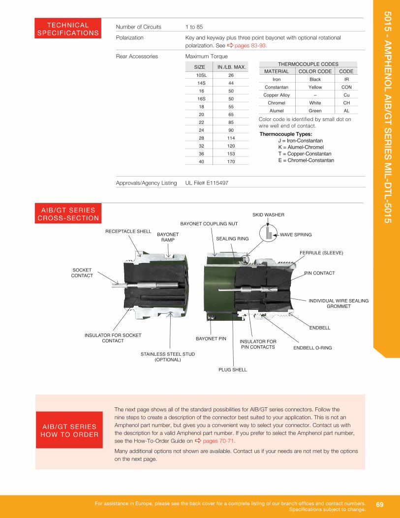
Number of Circuits 1 to 85
Polarization Key and keyway plus three point bayonet with optional rotational polarization. See apages 83-93.
Rear Accessories Maximum TorqueTHERMOCOUPLE CODES
MATERIAL COLOR CODE CODE Iron Black IR Constantan Yellow CON Copper Alloy – Cu Chromel White CH Alumel Green AL
10SL 26 14S 44 16 50 16S 50 18 55 20 65 22 85 24 90 28 114 32 120 36 153 40 170
SIZE IN./LB. MAX.
The next page shows all of the standard possibilities for AIB/GT series connectors. Follow the nine steps to create a description of the connector best suited to your application. This is not an Amphenol part number, but gives you a convenient way to select your connector. Contact us with the description for a valid Amphenol part number. If you prefer to select the Amphenol part number, see the How-To-Order Guide on a pages 70-71.
Many additional options not shown are available. Contact us if your needs are not met by the options on the next page.
INSULATOR FOR PIN CONTACTS
BAYONET RAMP
RECEPTACLE SHELL
BAYONET PIN
BAYONET COUPLING NUT
FERRULE (SLEEVE)
INSULATOR FOR SOCKET CONTACT
STAINLESS STEEL STUD(OPTIONAL)
PLUG SHELL
SEALING RINGWAVE SPRING
SOCKET CONTACT
SKID WASHER
Color code is identified by small dot on wire well end of contact.
Approvals/Agency Listing UL File# E115497
Thermocouple Types: J = Iron-Constantan K = Alumel-Chromel T = Copper-Constantan E = Chromel-Constantan
PIN CONTACT
ENDBELL
INDIVIDUAL WIRE SEALING GROMMET
ENDBELL O-RING
TECHNICAL SPECIFICATIONS
AIB/GT SERIES CROSS-SECTION
AIB/GT SERIES HOW TO ORDER
70
5015 - AMPH
ENO
L AIB/GT SERIES M
IL-DTL-5015
For assistance in North America: +1 800.642.8750 for Pricing/Delivery or +1 800.523.0727 Tech Support • www.peigenesis.com • [email protected]
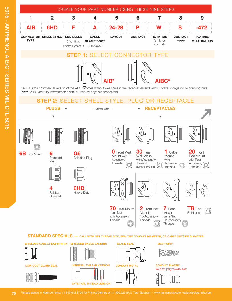
* AIBC is the commercial version of the AIB. It comes without wear pins in the receptacles and without wave springs in the coupling nuts. Note: AIBC are fully intermateable with all reverse bayonet connectors.
2 Front Box Mount No Accessory Threads
INTERNAL THREAD VERSION
EXTERNAL THREAD VERSION
AIB*
CONDUIT METAL
SHIELDED CABLE/HEAT SHRINK
G6 Shielded Plug
6 Standard Plug
4 Rubber- Covered
6HD Heavy-Duty
1 Cable Mount with Accessory Threads
30 Rear Wall Mount with Accessory Threads (Most Popular)
0 Front Wall Mount with Accessory Threads
20 Front Box Mount with Rear Accessory Threads
70 Rear Mount Jam Nut with Accessory Threads
TB Thru Bulkhead
LOW COST GLAND SEAL
GLAND SEALSHIELDED CABLE BANDING
6B Box Mount
7 Rear Mount Jam Nut No Accessory Threads
CONDUIT PLASTICaSee pages 444-445
MESH GRIP
AIBC*
CREATE YOUR PART NUMBER USING THESE NINE STEPS
AIB 6HD F A 24-28 P W S -472CONNECTOR
TYPESHELL STYLE END BELLS
(If omtting endbell, enter -)
CABLE CLAMP/BOOT
(If needed)
LAYOUT CONTACT ROTATION(omit for normal)
CONTACT TYPE
PLATING/ MODIFICATION
1 2 3 4 5 6 7 8 9
PLUGS RECEPTACLES
STEP 1: SELECT CONNECTOR TYPE
STEP 2: SELECT SHELL STYLE, PLUG OR RECEPTACLE
STANDARD SPECIALS — CALL WITH NPT THREAD SIZE, SEALTITE CONDUIT DIAMETER, OR CABLE OUTSIDE DIAMETER.
Mates with

71
5015 - AMPH
ENO
L AIB/GT SERIES M
IL-DTL-5015
For assistance in Europe, please see the back cover for a complete listing of our branch offices and contact numbers.Specifications subject to change.
TIP: Order connector, backshell and all accessories as one part number! See www.peigenesis.com/en/solution-guides.html
Heat Shrink BootCall with cable outisde diameter aSee pages 440-441.
RV No Clamp
G Heat Shrink L Long Extender A Unsealed (no grommet seal)
F Sealed (with grommet seal)
T MS Style (MS3108) 90º
P Potting *Potting CompoundaSee Page 443
STEP 4: SELECT CABLE CLAMP OR BOOT ( IF APPLICABLE)
C MS3057-CGland Seal aSee Page 112
A MS3057-AStandard Cable Clamp
9767 9767Gland Seal for smaller cable range.aSee Page 113
U Low-Cost Shielded
G2 Spin Coupling Heat Shrink
STEP 3: SELECT CABLE CLAMP OR BOOT ( IF APPLICABLE)
* When using a “C” in part number, the connector is supplied with the standard size crimp contacts for its layout. Bolded part numbers on apage 94-96 indicate crimp contact. Please call for connectors with reduced or enlarged crimp barrel contacts.a** See page 99 for post diameters and lengths.
MATERIALSL = Low-smoke, zero-halogenV = High-temperature Viton®*
*Viton® is a registered trademark of DuPont Dow Elastomers
P = Pin S = Socket PS =Style TB Only
STEP 5: SELECT LAYOUT STEP 6: SELECT CONTACT
aSee pages 72-82
aSee pages 83-93 (Omit for normal)W, X, Y, Z
STEP 7: SELECT ROTATION
S = Solder C = Crimp* H = PC** 0 = Less Contacts
STEP 8: SELECT CONTACT TYPE
STEP 9: SELECT PLATING
CONTACTS(Omit for silver contacts)
B30 = Gold 30µ” Gold over NickelT = Thermocouple (Solder only)RDS = RADSOK (Socket only) 12, 8, 4, 0
SHELL PLATING(Omit for olive drab chromate over cadmium)
023 = Nickel (RoHS with crimp or 116 contacts)024 = Green Zinc Cobalt025 = Black Zinc Alloy (RoHS with crimp or 116 contacts)027 = Conductive Black Zinc Alloy
(RoHS with crimp or 116 contacts)G96 = Black Anodized116 = Less Pre-tinned Solder Cups472 = 116 & 025 mod codes (RoHS)548 = 116 & 023 mod codes (RoHS)553 = 116 & 027 mod codes (RoHS)

72
5015 - AMPH
ENO
L AIB/GT SERIES M
IL-DTL-5015
For assistance in North America: +1 800.642.8750 for Pricing/Delivery or +1 800.523.0727 Tech Support • www.peigenesis.com • [email protected]
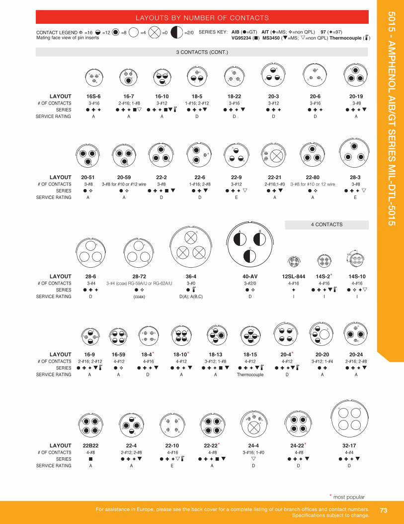
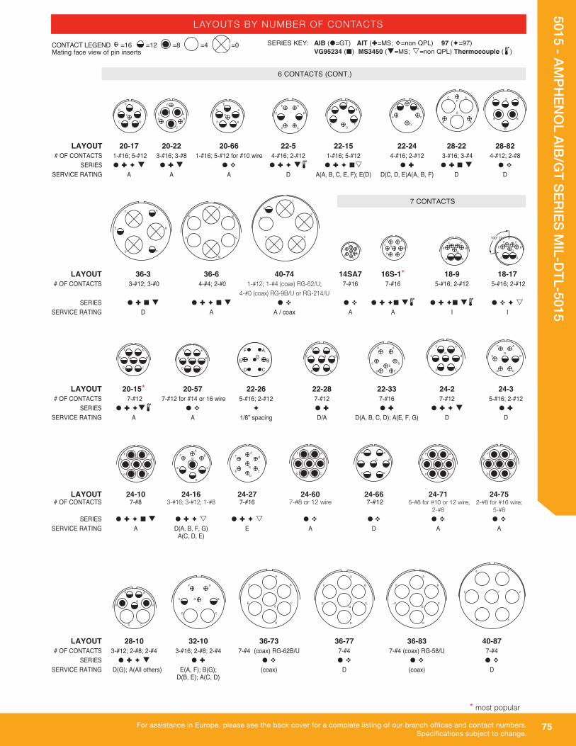
LAYOUTS BY NUMBER OF CONTACTS
LAYOUT 18-14 20-12 20-23 22-1 22-8 22-11 24-1 # OF CONTACTS 1-#16; 1-#4 1-#16; 1-#4 2-#8 2-#8 2-#12 2-#16 1-#12; 1-#0 SERIES Ìs Ì �Ìè �èÌ �Ìè �Ìès q SERVICE RATING A A A D E B D
1 CONTACT
LAYOUT 10SL-4* 12S-3* 12S-6 14S-9* 16S-4 16A11 16-11 16-13 18-3 # OF CONTACTS 2-#16 2-#16 2-#16 2-#16 2-#16 2-#12 2-#12 2-#12 2-#12 SERIES �Ìè¢q2 Ìèq2 è � Ìèq2 �Ìè¢s2 ¢ �Ìèq2 Ìq2 � Ìè SERVICE RATING A A Thermocouple A D A A Thermocouple D
3 CONTACTS
2 CONTACTS
SERIES KEY: AIB (�=GT) AIT (Ì=MS; v=non QPL) 97 (è=97) VG95234 (¢) MS3450 (q=MS; s=non QPL) Thermocouple (2)
LAYOUT 8S-1 10S-2 12S-4 12-5 14S-4 14-3 16S-3 16-2 # OF CONTACTS 1-#16 1-#16 1-#16 1-#12 1-#16 1#8 1#16 1-#12 SERIES Ì è q Ì q Ì q Ì è q �Ìè Ì q sÌ �Ìs SERVICE RATING A A D D D A B E
� � �
LAYOUT 16-12 18-6 18-7 18-16 18-420 20-2 22-7 24-52 # OF CONTACTS 1-#4 1-#4 1-#8 1-#12 1-#12 1-#0 1-#0 1-#12 SERIES � Ìè¢q �Ì q Ì� s � Ìès è �v ¢q �Ì q �v SERVICE RATING A D B C 17 KVac D E 21 KVac 24 KVdc 30 KVdc
�
A B B A
�
ABAB
A
B
AB
AB
A
B
A
B
A
B
AB
AB AB
ABAB
A
B
A
BC
CONTACT LEGEND =16 =12 =8 =4 =0 Mating face view of pin inserts
* most popular Pins in receptacle, sockets in plug only for 97/AIT/MS series
LAYOUT 24-9 28-7 32-5 10SL-3 14S-1 14S-7 14S-12 16S-5 # OF CONTACTS 2-#4 2-#4 2-#0 3-#16 3-#16 3-#16 3-#16 3-#16 SERIES �Ìè¢ �v �Ìè �Ìè ¢q Ì èq� �Ìèq2 �vès �Ìè SERVICE RATING A D D A A A A A
73
5015 - AMPH
ENO
L AIB/GT SERIES M
IL-DTL-5015
For assistance in Europe, please see the back cover for a complete listing of our branch offices and contact numbers.Specifications subject to change.
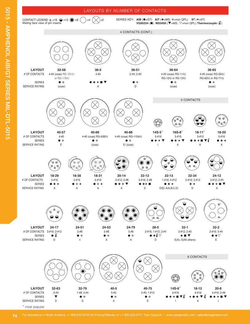
LAYOUTS BY NUMBER OF CONTACTS
LAYOUT 28-6 28-72 36-4 40-AV 12SL-844 14S-2* 14S-10 # OF CONTACTS 3-#4 3-#4 (coax) RG-59A/U or RG-62A/U 3-#0 3-#2/0 4-#16 4-#16 4-#16 SERIES � Ì è � v � 2 � v è � Ì è q2 � v ès SERVICE RATING D (coax) D(A); A(B,C) D I I I
LAYOUT 16S-6 16-7 16-10 18-5 18-22 20-3 20-6 20-19 # OF CONTACTS 3-#16 2-#16; 1-#8 3-#12 1-#16; 2-#12 3-#16 3-#12 3-#16 3-#8 SERIES � Ì è � Ì è ¢s � Ì è ¢q2 � Ì èq � Ì è q � Ì è � Ì è � Ì è q SERVICE RATING A A A D D D D A
LAYOUT 20-51 20-59 22-2 22-6 22-9 22-21 22-80 28-3 # OF CONTACTS 3-#8 3-#8 for #10 or #12 wire 3-#8 1-#16; 2-#8 3-#12 2-#16;1-#0 3-#8 for #10 or 12 wire 3-#8 SERIES � v � v � Ì è ¢ q � Ì q � Ì è s � Ì q � v � Ì è s SERVICE RATING A A D D E A A E
A B
CA
BC
A
BC
A
BC
A
B
C A
B
CA
B
C
A
BC
A
B
CA B
C
B
C A A
BC
A
BC
A
B
C
A
BC
A
BC
A
BC
A
BC
A
BC
LAYOUT 16-9 16-59 18-4* 18-10* 18-13 18-15 20-4* 20-20 20-24 # OF CONTACTS 2-#16; 2-#12 4-#12 4-#16 4-#12 3-#12; 1-#8 4-#12 4-#12 3-#12; 1-#4 2-#16; 2-#8 SERIES � Ì è q2 � v � Ì è q � Ì è q � Ì è ¢ q � Ì è q2 � Ì èq2 � Ì � Ì è q SERVICE RATING A A D A A Thermocouple D A A
A
BC
D
A B
C D
A
BC
DA
BC
D
A
B
C
D A
B
C
D
A
B
C
D
LAYOUT 22B22 22-4 22-10 22-22* 24-4 24-22* 32-17 # OF CONTACTS 4-#8 2-#12; 2-#8 4-#16 4-#8 3-#16; 1-#0 4-#8 4-#4 SERIES ¢ � Ì è q � Ì ès2 � Ì è ¢ q s � Ì è q � Ì è q SERVICE RATING A A E A D D D
A
B
D
C
A
B
C
DA
BC
D
A
BC
DA
BC
D
A
BC
D
A
BC
D
A
B
C
D
�A
B
C
D
SERIES KEY: AIB (�=GT) AIT (Ì=MS; v=non QPL) 97 (è=97) VG95234 (¢) MS3450 (q=MS; s=non QPL) Thermocouple (2)
CONTACT LEGEND =16 =12 =8 =4 =0 =2/0 Mating face view of pin inserts
* most popular
4 CONTACTS
3 CONTACTS (CONT.)
74
5015 - AMPH
ENO
L AIB/GT SERIES M
IL-DTL-5015
For assistance in North America: +1 800.642.8750 for Pricing/Delivery or +1 800.523.0727 Tech Support • www.peigenesis.com • [email protected]
LAYOUTS BY NUMBER OF CONTACTS
LAYOUT 24-17 24-51 24-53 24-79 28-5 32-1 32-2 # OF CONTACTS 3-#16; 2-#12 5-#8 5-#8 5-#8 2-#16; 1-#12; 2-#4 3-#12; 2-#0 2-#16; 3-#4 SERIES � 2 � v � v � v � Ì2s Ì ¢ q � Ìs SERVICE RATING D A A A D E(A); D(All others) E
AB
C
D
E A
B
C
D
E A
B
C
D
E A
B
C
D
E
A
B
CD
E
A
B
CD
E
A
B
C
D
E
6 CONTACTS A
B
GC
N
1
2
3
4
5
LAYOUT 18-29 18-30 18-31 20-14 22-12 22-13 22-34 24-12 # OF CONTACTS 5-#16 5-#16 5-#16 3-#12; 2-#8 3-#16; 2-#8 1-#16; 4-#12 2-#16; 3-#12 3-#12; 2-#4 SERIES � Ì è � v è � v è � Ì è q � Ìè ¢ � Ì è Ì è � Ì è ¢ q SERVICE RATING A A A A D D(E) A(A,B,C,D) D A
A
BC
D
EA
B
C
D
EA
B
CD
E A
BC
DE
A
BC
DE
A
B
C
D
E
LAYOUT 40-57 40-66 40-86 14S-5* 16S-8* 18-11* 18-20 # OF CONTACTS 4-#0 4-#0 (coax) RG-63B/U 4-#0 (coax) RG-115A/U 5-#16 5-#16 5-#12 5-#16 SERIES � v � v � v � Ì è q � Ì è q � Ì è¢ q2 � Ì è SERVICE RATING E (coax) E/ (coax) I A A A
1
2
3
4
1
2
3
4
1
2
3
4
5 CONTACTS
A
B
CD
EA
BC
DE
A
BC
D
EA B
CD
E
SERIES KEY: AIB (�=GT) AIT (Ì=MS; v=non QPL) 97 (è=97) VG95234 (¢) MS3450 (q=MS; s=non QPL) Thermocouple (2)
CONTACT LEGEND =16 =12 =8 =4 =0 Mating face view of pin inserts
4 CONTACTS (CONT.)
LAYOUT 32-63 32-79 40-5 40-75 14S-6* 18-12 20-8 # OF CONTACTS 5-#4 1-#8; 4-#4 5-#0 4-#0; 1-#12 6-#16 6-#16 4-#16; 2-#8 SERIES q � v � v � v � Ì è ¢ q2 è � Ì q 2 � Ì è ¢ q SERVICE RATING D D A E I A I
A
BC
D
E
F A
B
CD
E
A
B
C
D
EF
A
B
C
D
E F
A
BC
D
LAYOUT 32-58 36-5 36-51 36-64 36-65 # OF CONTACTS 4-#4 (coax) RG-161/U 4-#0 2-#4; 2-#0 4-#0 (coax) RG-11/U; 4-#0 (coax) RG-59/U; or RG-179/U RG-12/U or RG-13/U RG-62/U or RG-71/U SERIES � v � Ì è ¢ q � v � v � v SERVICE RATING (coax) A D (coax) (coax)
A
B
CD
A
B
C
D
A
B
C
D
A
B
C
D
* most popular
75
5015 - AMPH
ENO
L AIB/GT SERIES M
IL-DTL-5015
For assistance in Europe, please see the back cover for a complete listing of our branch offices and contact numbers.Specifications subject to change.
LAYOUTS BY NUMBER OF CONTACTS
LAYOUT 20-17 20-22 20-66 22-5 22-15 22-24 28-22 28-82 # OF CONTACTS 1-#16; 5-#12 3-#16; 3-#8 1-#16; 5-#12 for #10 wire 4-#16; 2-#12 1-#16; 5-#12 4-#16; 2-#12 3-#16; 3-#4 4-#12; 2-#8 SERIES � Ì è q � Ì q � v � Ì è q2 � Ì è ¢s � Ì � Ì ¢ q � v SERVICE RATING A A A D A(A, B, C, E, F); E(D) D(C, D, E)A(A, B, F) D D
AB
C
DE
F
LAYOUT 36-3 36-6 40-74 14SA7 16S-1* 18-9 18-17 # OF CONTACTS 3-#12; 3-#0 4-#4; 2-#0 1-#12; 1-#4 (coax) RG-62/U; 7-#16 7-#16 5-#16; 2-#12 5-#16; 2-#12 4-#0 (coax) RG-9B/U or RG-214/U SERIES � Ì ¢ q � Ì è ¢ q � v � v � Ì è¢ q2 � Ì è¢ q2 � v è s SERVICE RATING D A A / coax A A I I
A
BC
D
E
F
A
B
CD
E
FA
B
C
D
E
F
1
2
34
5
6
LAYOUT 20-15* 20-57 22-26 22-28 22-33 24-2 24-3 # OF CONTACTS 7-#12 7-#12 for #14 or 16 wire 5-#16; 2-#12 7-#12 7-#16 7-#12 5-#16; 2-#12 SERIES � Ì èq2 � v è � Ì � Ì � Ì è q � Ì SERVICE RATING A A 1/8” spacing D/A D(A, B, C, D); A(E, F, G) D D
A
F
ED
C
BG
A
B
CD
E
F
G
A
B
C
D
E
F
G
A
B
CD
E G
F A
B
CD
E G
FA
B
C
E
F
G
D
A
BCE
FG
D
A
B
CD
E
FG
100° �
A
B
C
D
E
F
G
LAYOUT 24-10 24-16 24-27 24-60 24-66 24-71 24-75 # OF CONTACTS 7-#8 3-#16; 3-#12; 1-#8 7-#16 7-#8 or 12 wire 7-#12 5-#8 for #10 or 12 wire, 2-#8 for #16 wire; 2-#8 5-#8
SERIES � Ì è ¢ q � Ì è s � Ì è s � v �v � v � v SERVICE RATING A D(A, B, F, G) E A D A A A(C, D, E)
A
B
C
E
F
G
D
A
B
CD
E
FG
A
B
CD
E
FG
A
B
CD
E
FG
A
B
CD
E
F
G
A
B
C
D
E
F
G
A
B
CD
E
F
G
6 CONTACTS (CONT.)
LAYOUT 28-10 32-10 36-73 36-77 36-83 40-87 # OF CONTACTS 3-#12; 2-#8; 2-#4 3-#16; 2-#8; 2-#4 7-#4 (coax) RG-62B/U 7-#4 7-#4 (coax) RG-58/U 7-#4 SERIES � Ì è q � Ì � v � v � v � v SERVICE RATING D(G); A(All others) E(A, F); B(G); (coax) D (coax) D D(B, E); A(C, D)
A
B
C
D
E
F
G
A
B
C
D
E
F
G
1
2
34
5
6
7
A
B
C
D
E
FG
A
B
CD
E
F
G
AB
CD
E
F
G
A
B
CD
E
F
G
A
BC
D
E
F
A
B
CD
E
F
1 23
4 5
6
A
B
E
F
CD
A
B
C
D
E
F
A
B
C
DE
F
SERIES KEY: AIB (�=GT) AIT (Ì=MS; v=non QPL) 97 (è=97) VG95234 (¢) MS3450 (q=MS; s=non QPL) Thermocouple (2)
CONTACT LEGEND =16 =12 =8 =4 =0 Mating face view of pin inserts
7 CONTACTS
* most popular

76
5015 - AMPH
ENO
L AIB/GT SERIES M
IL-DTL-5015
For assistance in North America: +1 800.642.8750 for Pricing/Delivery or +1 800.523.0727 Tech Support • www.peigenesis.com • [email protected]
LAYOUTS BY NUMBER OF CONTACTS
10 CONTACTS
LAYOUT 18-1* 18-19 18-24 20-58 24-21 28-19 # OF CONTACTS 10-#16 10-#16 10-#16 5-#16; 5-#12 9-#16; 1-#8 6-#16; 4-#12 SERIES � Ì è ¢ q2 � v è s � v ès � v � Ì è s � Ì è s SERVICE RATING A (B, C, F, G) A A(B, C, F, G); A D B(H, M); D(A, B) I(all others) I(balance) A(C,E,G,J,K,L)
A
B
CDE
F
GH
I
J
AB C
D E F G
H
K
J
AB
C
D
E
F
G
H
J K
A BC
E
GH
J
K
L
MA
BC
D E
F
HJ
K
L
A B C
D E F
G
H
I
LAYOUT 28-1 28-4 28-84 28AY 32-3 32-75 # OF CONTACTS 6-#12; 3-#8 7-#16; 2-#12 9-#8 5-#16; 4-#4 4-#16; 2-#12; 2-#4; 1-#0 2-#12; 7-#8 (coax) RG-180B/U SERIES � Ì è q � Ì s � v � v � Ì ¢ s � v SERVICE RATING D(A, J, E); E(G, P, S); A A D (coax) A(all others) D(all others)
A B
C
DEF
G
H
J
A B
C DP
S
E FG
A
BC
DE
FG
H
I
AB C
D E F
G H
J
AB
C
D E F
G
H
J
1
2
34
5
6 7
8 9
LAYOUT 20-18* 20-21 22-16 22-17 22-20 22-27 24-11 # OF CONTACTS 6-#16; 3-#12 8-#16; 1-#12 6-#16; 3-#12 8-#16; 1-#12 9-#16 8-#16; 1-#8 6-#12; 3-#8 SERIES � Ì è q � Ì è q � Ì è 2 � Ì s � Ì è � Ì è ¢ s � Ì è ¢ q SERVICE RATING A A A D(A); A(all others) A D(J); A(all others) A
AB
C
DE
F
G
HI
A
B
C
D
E
F G H
J
AB
C
D
E
F
GH
J
AB
C
D
E
F
G
H
J
A
B
CDE
F
G H
J
AB
C
D
E
FG
H
LAYOUT 24-6 32-15 32-52 32-57 40-AD 20A9 20-16 # OF CONTACTS 8-#12 6-#12; 2-#0 6-#12; 2-#0 6-#12; 2-#0 (coax) RG-7/U 4-#8; 4-#0 9-#12 7-#16; 2-#12 SERIES � Ì è s � Ì q � v � v � v ¢ � Ì èq SERVICE RATING D(A, G, H); D D (coax) A D(J), I(all others) A A(all others)
A
B C
D E
F
G
H
A
B C
D E
F
G
H
9 CONTACTS
AB
C
D
EF
G
HI
AB
CD
E
FG
H
I
SERIES KEY: AIB (�=GT) AIT (Ì=MS; v=non QPL) 97 (è=97) VG95234 (¢) MS3450 (q=MS; s=non QPL) Thermocouple (2)
CONTACT LEGEND =16 =12 =8 =4 =0 Mating face view of pin inserts
8 CONTACTS
A
B
C
DE
F
GH
A
B
C
DE
F
G H
AB
C
DE
F
G
HA
B
CD
E
FG
H
LAYOUT 18-8* 20-7* 20-9 20-79 22-18 22-23 22-36 22-65 # OF CONTACTS 7-#16; 1-#12 8-#16 7-#16; 1-#12 7-#16; 1-#12 for #16 wire 8-#16 8-#12 8-#12 8-#12 for #14 or 16 wire SERIES � Ì è q � Ì èq2 Ì v s � v � Ì è s � Ì èq2 s � v SERVICE RATING A A (B,C,F,G) DCH; DCH; D(A, B, F, G, H); D(H); D(H) D(H); A(all others) I(all others) A(all others) A(all others) A(C, D, E) A(all others) A(all others)
A
B
CD
E
F
G
H
A
B
CD
E
FG
H
A
B
CD
E
FG
H
* most popular

77
5015 - AMPH
ENO
L AIB/GT SERIES M
IL-DTL-5015
For assistance in Europe, please see the back cover for a complete listing of our branch offices and contact numbers.Specifications subject to change.
LAYOUTS BY NUMBER OF CONTACTS
LAYOUT 20-33 24-20 36-14 40-67 40-72 40-80 # OF CONTACTS 11-#16 9-#16; 2-#12 6-#16; 5-#12; 5-#8 1-#16; 10-#4 (coax) RG-59/U 1-#16; 10-#4 (coax) RG-9B/U 10-#4; 1-#16 SERIES � Ì è q � Ì èq2 � Ì � v � v � v SERVICE RATING A D D A (coax) A (coax) A
AB
C
DEF
K
H
J M
L
AB
C
D
EF
G
H
J
K L
A
B
C
D
E
F
G
H
J
K
L
M
N
I P
Q
A B
C D E
F H
I
J
K LM
N
A B
C D E
F H
I
J
K LM
N
A B
C D E
F H
I
J
K LM
N
11 CONTACTS
LAYOUT 22-63 24-19 28-8 28-9 28-18 28-51 # OF CONTACTS 8-#16; 4-#12 12-#16 10-#16; 2-#12 6-#16; 6-#12 12-#16 12-#12 SERIES � v �è � Ì è s � Ì è q � Ì è s � v SERVICE RATING A A E(L,M,); D(B) A(balance) D C(M); D(G, H, J, K, L) A A(A, B); I(C,D,E,F)
A
B
CD
E
F
G
H
J
K
L
M
AB
C
D
E
FGH
J
K
L
MA
B C
EF
HJ
K
L
MN
D
A
B
C
DE
F
H
J
K
L
M
N
12 CONTACTS
13 CONTACTS
LAYOUT 20-11 20-25 20-30 22-70 24-58 32-14• 20-27* # OF CONTACTS 13-#16 13-#16 13-#16 5-#16; 8-#12 7-#16; 3-#12; 3-#8 13-#12 14-#16 SERIES � Ì è � v è � v è � v � v v � Ì èq2 SERVICE RATING I I I A A D A
A
B C
D
E
F
G H
J
K
L
M
N
A
B
C
DE
F
H
JK
LM
N
P
AB
C
D
E
F
HJ
K
LM
N
P
AB
C
D
EF
G
H
J
KL
M
N
P
AB
CD
EFG
H
IJ
K
L
M
N
A
B
CD
E
F
H
JK
LM
NP
R
14 CONTACTS
A
B
C
D
EF
G
H
J
K
L
M
N
P
A
B
C
D
EF
G
H
J
K
LM
NP
A B
C D E F G
H I J K
L M N
1
2
3
4
56
7
8
9
10
11
12
13
14
A
B
C
D
E
F
G
H
J
K
L
M
N
O
AB
C
D
E
FJ
L
MN
H
K
A
B
C
DE
F
G
HJ
K
LM
SERIES KEY: AIB (�=GT) AIT (Ì=MS; v=non QPL) 97 (è=97) VG95234 (¢) MS3450 (q=MS; s=non QPL) Thermocouple (2)
CONTACT LEGEND =16 =12 =8 =4 =0 Mating face view of pin inserts
LAYOUT 22-19* 24-59 28-2 28-20 32-4 32-9 36-78 # OF CONTACTS 14-#16 7-#16; 7-#12 12-#16; 2-#12 4-#16; 10-#12 12-#16; 2-#12 12-#16; 2-#4 12-#8; 2-#16 SERIES � Ì èq2 � v � Ì è q � Ì è¢ q2 � Ì � Ì q � v SERVICE RATING A A D A A(F, J, K, N); D A D(all others)
• different per 1651 STD: 5-#12; 2-#4 * most popular
78
5015 - AMPH
ENO
L AIB/GT SERIES M
IL-DTL-5015
For assistance in North America: +1 800.642.8750 for Pricing/Delivery or +1 800.523.0727 Tech Support • www.peigenesis.com • [email protected]
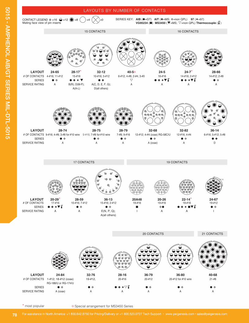
LAYOUTS BY NUMBER OF CONTACTS
LAYOUT 24-84 32-76 28-16 36-79 36-80 40-68 # OF CONTACTS 1-#12; 18-#12 (coax) 19-#12, 20-#16 20-#12 20-#12 for #10 wire 21-#8 RG-188/U or RG-174/U SERIES � v � v � Ì ès2 � v � v � v SERVICE RATING A (coax) A A A A A
AB
C
D
EF
G
H
J
K
L M
NU
V
RS
T P
90° �
A
B
C
DE
F
G
H
J
KL
M
N
PR
S
TU
V
1 2 3
4 5 6 7
8 9 10 11 12
13 14 15 16
17 18 19
19 CONTACTS
AB
C
D
EFG
H
J
K
L M
PQR
S
T
UV N
1
2 3 4 5
6 7 8 9 10
11 12 13 14 15
16 17 18 19
20
1
2 3 4 5
6 7 8 9 10
11 12 13 14 15
16 17 18 19
20
A
B
C
D
E
F
G
H
J
K
L
M
N
P
R
S
TU
V
W
X
20 CONTACTS 21 CONTACTS
LAYOUT 20-29* 28-59 36-13 20A48 20-26 22-14* 24-67 # OF CONTACTS 17-#16 10-#16; 7-#12 15-#16; 2-#12 19-#16 19-#16 19-#16 19-#12 SERIES � Ì èq2 � v � v ¢ v� � Ì è ¢q2 � v SERVICE RATING A A E(N, P, Q); I A A I A(all others)
A BC
D
E
FGH
J
K
L
MN
PT
S R
A
B
C
DEF
G
H
J
K
LM
NP
Q
R S
A B C D
EF
H
J K
L M N
P R S T U
17 CONTACTS
SERIES KEY: AIB (�=GT) AIT (Ì=MS; v=non QPL) 97 (è=97) VG95234 (¢) MS3450 (q=MS; s=non QPL) Thermocouple (2)
CONTACT LEGEND =16 =12 =8 =4 =0 Mating face view of pin inserts
LAYOUT 28-74 28-75 28-79 32-68 32-82 36-14 # OF CONTACTS 9-#16; 4-#8; 3-#8 for #10 wire 9-#16; 7-#8 for #10 wire 7-#8; 9-#16 12-#12; 4-#4 (coax) RG-58C/U 12-#16; 4-#4 6-#16; 5-#12; 5-#8 SERIES � v � v � v � v � v � Ì SERVICE RATING A A A A (coax) A D
AB
CD
EFH
J
KL
MN
PR
S
T
AB
CD
EFH
J
KL
MN
PR
S
T
AB
CD
EFH
J
KL
MN
PR
S
T
A B
C DE
F G HJ
K L M
N P
Q R
A B
C DE
F G HJ
K L M
N P
Q R
A
B
C
D
E
F
G
H
J
K
L
M
N
I P
Q
LAYOUT 24-65 28-17* 32-12 40-5¤ 24-5 24-7* 28-66 # OF CONTACTS 4-#16; 11-#12 15-#16 10-#16; 5-#12 6-#12; 4-#8; 2-#4; 3-#0 16-#16 14-#16; 2-#12 14-#12; 2-#8 SERIES � v � Ì è q � Ì s � Ì èq2 � Ì èq2 � v SERVICE RATING A B(R); D(M-P); A(C, D, E, F, G); A A A A A(A-L) D(all others)
A B
C D E F G
H J K
L M
O P
N
A
BC D
EFG
H J KL
M
N
P
R
A
B
C
DE
F
H
J
KL
MN
PR
S
15 CONTACTS
A BC
D EF G H
J KL M N
PS
R
AB
C
D
EF
GH
J
KL
MNP
I O
16 CONTACTS
AB
C
D
E
F
HJ
K
L
M
N
PR
S
T
¤ Special arrangement for MS3450 Series* most popular

79
5015 - AMPH
ENO
L AIB/GT SERIES M
IL-DTL-5015
For assistance in Europe, please see the back cover for a complete listing of our branch offices and contact numbers.Specifications subject to change.
LAYOUTS BY NUMBER OF CONTACTS
12
3
4
5
6789
10
11
12
13
1415 16
17
18
1920
21
22
2324
25
26
27
28
ABC D
E
HKGJF
L
QPN
I
M
R S
O
VY
Z
W
U
X
ba
c
T
28 CONTACTS 29 CONTACTS
LAYOUT 28-11* 36-1 36-22 40-7 24-80 # OF CONTACTS 18-#16; 4-#12 18-#16, 4-#12 22-#12 18-#16; 2-#12; 2-#0 23-#16 SERIES � Ì è¢ q2 � Ì è � v s � vs SERVICE RATING A D D P, Q, U, V, W, X=A; I D(balance)
A
B
C
D
E
F
G
H
J
K
L
MI
N
P
R
S
T
U
V
W
X
A B C
D E F G H
I J K L M N
O P R S T
U V W
22 CONTACTS
LAYOUT 32-6 32-13 32-16 32-60 32-62 40-2 # OF CONTACTS 16-#16; 2-#12; 18-#16; 5-#12 16-#16; 2-#12; 15-#16; 8-#8 (coax) 16-#16; 2-#12; 1-#8; 23-#16 3-#8; 2-#4 3-#8; 2-#4 RG-124/U 2-#8 (coax) RG-124/U; 2-#4 SERIES � Ì è ¢ q � Ì è q � v s � v � v s SERVICE RATING A D A A (coax) A (coax) D
A B C D
E F G H J
K L M N P Q
RS T U
V
W X Z
AB
C
D
E
F
G
H
J
K
L
MN
PR
S
T
U
V
W
XY
Z
A BC D
E FG HJ
K L M N
O
P R
ST
U VW
I
X
A BC D
E FG HJ
K L M N
O
P R
ST
U VW
I
X
A
B
CD
E
F
H
J
K
LM
N
P
R
ST
U
VW
X
Y
Z
a
23 CONTACTS
SERIES KEY: AIB (�=GT) AIT (Ì=MS; v=non QPL) 97 (è=97) VG95234 (¢) MS3450 (q=MS; s=non QPL) Thermocouple (2)
CONTACT LEGEND =16 =12 =8 =4 =0 Mating face view of pin inserts
24 CONTACTS
26 CONTACTS
25 CONTACTS
LAYOUT 28-12* 28-13 40-6 24-96 28A63 40-10 # OF CONTACTS 26-#16 26-#16 24-#16; 1-#12; 1-#0 28-#16 19-#16; 9-#12 16-#16; 9-#8; 4-#4 SERIES � Ì èq2 � v è s s � v ¢ � Ì SERVICE RATING A A D I A A
A B C D
E F G H J
K L M N P Q
R S T U V
W X Y Z
AB C
DGE F H J
K L M N P QT
R S U VW Z
X Ya
1312
11
10
9
87
6
5
4
3
21
23
19 2221
20
15
18
1716
14
2425
A
B
C
D
E
FG
HJ
K
L
M
PR
N
ST
U
V
WX
Y
Z
ab
d
23 CONTACTS (CONT.)
LAYOUT 40-3 40-4 24-28* 24-AJ 32-25 # OF CONTACTS 18-#16; 4-#12; 1-#4 16-#16; 2-#12; 3-#8; 2-#4 24-#16 25-#16 25-#12 SERIES s s � Ì è¢ q2 � v � v SERVICE RATING D D I A A
* most popular

80
5015 - AMPH
ENO
L AIB/GT SERIES M
IL-DTL-5015
For assistance in North America: +1 800.642.8750 for Pricing/Delivery or +1 800.523.0727 Tech Support • www.peigenesis.com • [email protected]
39 CONTACTS
LAYOUT 32-53 32-59 40-AT 36-74 32-73 # OF CONTACTS 37-#16; 5-#12 40-#16; 2-#8 (coax) RG-161/U 18-#16; 24-#12; 1-#8 43-#16; 1-#8 (coax); RG-187B/U 46-#16 SERIES � v � v � v � v � v q SERVICE RATING I/E A (coax) A A (coax) A
42 CONTACTS
A B C D E
F
H
J
KL
M N PR
S
T
U
VW
XY
Za b c
d
fgh
ij k
m
np
r
t uv w
sq
A BC
D
E
F
H
J
KL
MNPR
ST
U
V
W
XY
Za b
c
d
fg
h
ij
k m
n
p
r t
s
q
A BC
D
E
F
H
J
KL
MNPR
ST
U
V
W
XY
Za b
c
d
fg
h
ij
k m
n
p
r t
s
q
44 CONTACTS 46 CONTACTS
48 4950 51 52
53 5455 56 57
58 59 60 6162 63 64 65 66
67 68 69 7071 72 73 74 75
76 77 78 7980 81 82 83
84 8586 87
88 8990
91
12
3
4
5
6
7
89
101112
13
14
15
16
17
1819
20 21
2223
24
25
26
2728
293031
32
33
34
3536
37
38
39
4041
42
43
4445
46
SERIES KEY: AIB (�=GT) AIT (Ì=MS; v=non QPL) 97 (è=97) VG95234 (¢) MS3450 (q=MS; s=non QPL) Thermocouple (2)
CONTACT LEGEND =16 =12 =8 =4 =0 Mating face view of pin inserts
LAYOUT 40-64 28-21* 40-AG 36-54 36-55 # OF CONTACTS 20-#16; 3-#12; 13-#8 (coax) RG-124/U 37-#16 38-#12 31-#16; 8-#8 31-#16; 8-#8 for #6 wire SERIES � v � Ì è ¢ q2 � v � v � v SERVICE RATING (coax) A A A A
36 CONTACTS 38 CONTACTS 37 CONTACTS
1
2
3
45
6
7
89
10
11
12
131415
16
17
18
19
2021
22
23
24
25
26
27282930
31
32
33
34
35
36
3738A
B
C
D
E
FH
J
K
L
M
NP
R S
T
U
V
W
X
YZa
b
c
d
f
gh
i
j
km
n
p
qA
B CD
E F G H JK L M N P R
S T U V W X Z
a b c d e f
gh
jk m
n p r s
43 CONTACTS
LAYOUT 32-8 32-56 40-1 32-31 36-9 36-18 # OF CONTACTS 24-#16; 6-#12 24-#16; 6-#12 for #10 wire 24-#16; 6-#12 31-#16 14-#16; 14-#12; 2-#8; 1-#4 14-#16; 14-#12; 2-#8; 1-#4 SERIES � Ì è2 � v � Ì q � v � Ì è q � v s SERVICE RATING A A D A A A
A
B
C
D
E
F
G
H
I
J
K
L
M
N
O
P
R
S
T
U
V
W
X
Y
Z
a
b
c
d
e
A
B
C
D
E
F
G
H
I
J
K
L
M
N
O
P
R
S
T
U
V
W
X
Y
Z
a
b
c
d
e
30 CONTACTS
34 CONTACTS
A B C
D E F G
H I J K L
M N O P R S
T U V W X
Y Z a b
c d e
12
3
4
5
6
78
910
11
12
13
14
15
16
17
1819
20
21
22
2324
2526 27
28
29
30 31
A B
C D E F G
H J K L M N
P R S T U V W
X Y Z a b c
d e f gh j
k m
35 CONTACTS
LAYOUT 36-20 28-15* 32-7* 36-15 36-85 40-35 # OF CONTACTS 30-#16; 2-#12; 2-#8 35-#16 28-#16; 7-#12 35-#16 35-#16 for #12 wire 35-#12 SERIES � v � Ì èq2 � Ì è ¢ q � Ì èq2 � v � v SERVICE RATING A A I(A, B, H, J); A(all others) D(M); A(balance) A/D D
A
B
C
D
E
F
G
H
I
J
K
L
M
N
O
P
R
S
T
U
V
W
X
Y
Z
a
b
c
d
e
f
g
h
j
k
AB
C
D
E
F
G
HJ
K
L
M
N
P
Q
RS
TU
V
W
X
YZ
a
b
c
d
e
f
gh
j
k
m
AB
C
D
E
F
GHJ
K
L
M
N
P
Q
R S
TU
V
W
XYZ
a
b
c
d
f
gh
j
k
m
eA B
C D E F G
H J K L M
P R S T
N
W
X Y Z
U V
a b c
de
f
gh
j k
ml
1
2
3
4
5
6
7
89
10
11
12
13
14
1516
17 18
19
20
21
222324
25
26
27
28
29
30
3132
33
34
35
31 CONTACTS
LAYOUTS BY NUMBER OF CONTACTS
* most popular

81
5015 - AMPH
ENO
L AIB/GT SERIES M
IL-DTL-5015
For assistance in Europe, please see the back cover for a complete listing of our branch offices and contact numbers.Specifications subject to change.
52 CONTACTS
LAYOUT 36-403 36-59 36-71 # OF CONTACTS 52-#16 50-#16; 3-#12 for #10 wire 50-#16; 3-#12 SERIES è � v � v SERVICE RATING A A A
A B C D
E F H J K
L M N P R S T U
V W X Y Z a b
c d f g h i j k
m n p r tu v w
s
x y zq
AA AB
ACAD
AE
AF
AH
AJ
A B C D
E F H J K
L M N P R S T U
V W X Y Z a b
c d f g h i j k
m n p r tu v w
s
x y zq
AA AB
ACAD
AE
AF
AH
AJ
A B C D
E F H J K
L M N P R S
T U V W X Y Z
a b c d f g h i
j k m n p r
t u v ws x
y z
q
AA ABAC
ADAE AF
AH
53 CONTACTS
1 2
3 4 A
5 6 7
8 9 10 C
11 12 13 14
15 16 17 +
2018 19
23
22
24
21
�
�
ABC
EFG
ZY
X
bd f
x
r
ae
3
f
D
HJ
S R
Q P N M L K
�
TUVW
c
l kn
y w
m j h g
2z
t rs
vu p
6 5 4
LAYOUT 36-7* 36-8 36-16 36-17 36-60 # OF CONTACTS 40-#16; 7-#12 46-#16; 1-#12 40-#16; 7-#12 40-#16; 7-#12 40-#16; 7-#12 for #10 wire SERIES � Ì èq2 � Ì èq2 � v s � v s � v SERVICE RATING A A A A A
47 CONTACTS
AB C
D EFG H
I J K LMN O P RS
T UV
WX
YZ
a
b c d ef g h jk
mn p rtu
v ws
x yz
A BC
DE
F GH I J
K L M NO P R S T
U V W X
Y Z a b c
d e f gh j k m
n p
r
t
s
u v
x yz
w
LAYOUT 36-76 40-9 32-48 36-10* 36-11 # OF CONTACTS 47-#16 24-#16; 22-#12; 1-#8 48-#16 48-#16 48-#16 SERIES � v �Ì q � v � Ì è ¢ q2 � Ì ès SERVICE RATING A A I A A
1 23
4 56 7 8
9 10 11 1213 14 15 16 17
18 19 20 2122 23 24 25 26
27 28 29 3031 32 33 34 35
36 37 38 3940 41 42
43 4445
46 47
A BC
D EF
G H I J K L
M N O P Q R S T
U V W X Y Z a
b c de f
g h i
jk
l m
n
pr
t us
o
q
A BC
DE
F GH I J
K L M NO P R S T
U V W X
Y Z a b c
d e f gh j k m
n p
r
t
s
u v
x yz
w
LAYOUT 36-12 36-75 36-AF 32-414 36-52 # OF CONTACTS 48-#16 48-#16 for #14 wire 48-#16 52-#16 52-#16 SERIES � Ì ès � v � v è � Ì q2 SERVICE RATING A A A A A
1 2
3 4 5
6 7
89
10 11
1213
1415
16
17
18
19
202122
2324
25
2627
28
29
30
31 32
33 34
3536
37
38
394041
42 43
4445
4647
48
AB
C
D
E
FG
HJK
L
M
N
OP
Q
RS
T
UV
W
X
Y
Z
ab
c
d ef
g
h
j
k
mn
pr
ts
q
u
v
w
xy
z110° �
A B
C D E F G
H J K L M N
O P Q R S T U
V W X Y Z a b c
d e f g h j k
m n p r
t u v w
s
x
y z
q
A B
C D E F G
H J K L M N
O P Q R S T U
V W X Y Z a b c
d e f g h j k
m n p r
t u v w
s
x
y z
q
100° �A B
C D E F G
H J K L M N
O P Q R S T U
V W X Y Z a b c
d e f g h j k
m n p r
t u v w
s
x
y z
q
SERIES KEY: AIB (�=GT) AIT (Ì=MS; v=non QPL) 97 (è=97) VG95234 (¢) MS3450 (q=MS; s=non QPL) Thermocouple (2)
CONTACT LEGEND =16 =12 =8 =4 =0 Mating face view of pin inserts
48 CONTACTS
LAYOUTS BY NUMBER OF CONTACTS
* most popular

82
5015 - AMPH
ENO
L AIB/GT SERIES M
IL-DTL-5015
For assistance in North America: +1 800.642.8750 for Pricing/Delivery or +1 800.523.0727 Tech Support • www.peigenesis.com • [email protected]
LAYOUTS BY NUMBER OF CONTACTS
SERIES KEY: AIB (�=GT) AIT (Ì=MS; v=non QPL) 97 (è=97) VG95234 (¢) MS3450 (q=MS; s=non QPL) Thermocouple (2)
CONTACT LEGEND = 20 =16 =12 =8 =4 =0 Mating face view of pin inserts
12
34
5
6
7
8
9
1011
121314
15
16
17
18
19
20
21
2223
24
25 2627
28
29
30
31
32
3334
35
36
37
38
39
40
4142
43 44
45
46
47
48
49
50
51
52
53
5455
56
57
58
59
6061
62 CONTACTS
LAYOUT 40-70 40-73 40-81 40-82 # OF CONTACTS 61-#16 61-#16 62-#16 for #14 wire 62-#16 SERIES � v � v � v � v SERVICE RATING A A A A
A B C D
E F H J K L M
N P R S T U V W
X Y Z a b c d f g
h i j k m n p r
t u v w
s
x y z
q
AA AB
AC AD AE AF AH AJ AK AL AM AN
AP AR AS AT AU AV AW AX AY
AZ BA BB
BV
BC BD BE BF BH
BJ BK BL BM BN
BS BT BU
BP BR
1 2 3 4
5 6 7 8 9 10 11
12 13 14 15 16 17 18 19
20 21 22 23 24 25 26 27 28
29 30 31 32 33 34 35 36
37 38 39 40 41 42 43 44 45
46 47 48 49 50 51 52 53
54 55 56 57 58
59 60 61 62
1 2 3 4
5 6 7 8 9 10 11
12 13 14 15 16 17 18 19
20 21 22 23 24 25 26 27 28
29 30 31 32 33 34 35 36
37 38 39 40 41 42 43 44 45
46 47 48 49 50 51 52 53
54 55 56 57 58
59 60 61 62
85 CONTACTS
54 CONTACTS
LAYOUT 32-22 32-64 32-AF 36-66 40-61 # OF CONTACTS 54-#16 54-#16 55-#16 52-#16; 4-#12 55-#16; 3-#12; 1-8 SERIES � v s � v � v s � v SERVICE RATING A I A A A
55 CONTACTS
1 23 4 5 6 7
8 9 10 11 12 13 14 15
16 17 18 19 20 21 22 23 24
25 26 27 28 29 30 31 32
33 34 35 36 37 38 39 40 41
42 43 44 45 46 47 48 49
50 51 52 53 54 55 56
57
58
59
A BC D E
F G H JK L M
N O P RS T U V W
X Y Z a
b c d e f
g h j km n p r
tq
s u vx y
z AAAB AC
AD AEAF AG
w
A BC D E
F G H JK L M
N O P RS T U V W
X Y Z a
b c d e fg h j k
nm p rt u v
ws
x yz
q
AAAB AC
AD AEAF AG
AH
A BC D E
F G H JK L M
N O P RS T U V W
X Y Z ab c d e f
g h j km n p r
t u vw
sx y
z
q
AAAB AC
AD AEAF AG
59 CONTACTS
12
34
5
6
7
8
910
1112
1314
1516
17
18
19
20
2122
2324
2526
2728
29
30
3132
333536
37
38
39
4041
4243
4445
46
47
34
4849
5051
52
5354
5556
5758
59
60
12
3
4
5
6
7
8
9
1011
12131415
16
17
18
19
20
21
2223
24
2526
2728
29
30
3132
333435
36
37
38
39
40
4142
43 44
45
46
47
484950
51
52
5354
55
56
57
5859
60
12
3
4
5
6
7
8
9
1011
12131415
16
17
18
19
20
21
2223
24
2526
2728
29
30
3132
333435
36
37
38
39
40
4142
43 44
45
46
47
484950
51
52
5354
55
56
57
5859
60
61 CONTACTS
LAYOUT 40-53 40-62 40-85 32A69 40-63 # OF CONTACTS 60-#16 60-#16 60-#16 for #14 wire 41-#20; 20-#16 61-#16 for #14 wire SERIES � v2 � Ì s � v ¢ � v SERVICE RATING A A A I A
1
2 3 4 5
6 7 8 9 10
11 12 13 14 15 16 17 18
19 20 21 22 23 24 25 26 27
28 29 30 31 32 33 34 35
36 37 38 39 40 41 42 43 44
45 46 47 48 49 50 51 52
53 54 55 56 57
58 59 60 61
12
34
5
6
7
8
9
1011
121314
15
16
17
18
19
20
21
2223
24
25 2627
28
29
30
31
32
3334
35
36
37
38
39
40
4142
43 44
45
46
47
48
49
50
51
52
53
5455
56
57
58
59
6061
60 CONTACTS
56 CONTACTS
LAYOUT 40-56 # OF CONTACTS 85-#16 SERIES � Ìq2 SERVICE RATING A
* most popular

83
5015 - AMPH
ENO
L AIB/GT SERIES M
IL-DTL-5015
For assistance in Europe, please see the back cover for a complete listing of our branch offices and contact numbers.Specifications subject to change.
DEGREES OF ROTATIONCONTACTS SIZES
SERVICE RATING LAYOUT 20 16 12 8 4 0 W X Y Z
8S-1 è Ì q 1 1 - - - - A
10S-2 Ì^ q 1 1 - - - - A
10SL-3 è Ì � ¢ q 3 3 - - - - A
10SL-4 è Ì^ � ¢ q 2 2 63# - - - A
10SL-51 v � s 2 2 2 10SL-4 45º A=Ir.; B=Con.
10SL-52 v � s 2 2 2 10SL-4 45º A=Cu; B=Con.
10SL-53 v � s 2 2 2 10SL-4 45º A=Al.; B=Ch.
10SL-54 v � s 3 3 2 10SL-3 A=Ir.; B=Con.; C=Cu
10SL-55 v � s 3 3 2 10SL-3 A=Al.; B=Ch.; C=Cu
10SL-56 v � s 2 2 2 10SL-4 A=Al.; B=Ch.
10SL-57 v � s 2 2 2 10SL-4 A=Ch.; B=Con.
10SL-58 v � s 3 3 2 10SL-3 A=Ch.; B=Al.; C=Cu
10SL-59 v � s 2 2 2 10SL-4 A=Ch.; B=Al.
10SL-60 v � s 2 2 2 10SL-4 A=Ir.; B=Con.
10SL-61 v � s 2 2 2 10SL-4 A=Cu; B=Con.
10SL-62 v � s 3 3 2 10SL-3 A=Cu; B=Al.; C=Ir.
10SL-63 v � s 3 3 2 10SL-3 A, C=Con.; B=Ch.
10SL-64 v � s 3 3 2 10SL-3 A, C=Ch.; B=Al.
12S-1 v s 2 2 12S-3 100º A
12S-2 è v s 2 2 12S-3 250º A
12S-3 è Ì q 2 2 70 145 215 290 A
12S-4 Ì q 1 1 - - - - D
12S-6 è 2 2 2 12S-3 A=Con.; B=Ir.
12S-51 v s 2 2 2 12S-3 315º A=Ch.; B=Al.
12S-54 v s 2 2 2 12S-3 315º A = Ir.; B=Con.
12S-55 v s 2 2 2 12S-3 45º A=Cu; B=Con.
12S-56 v s 2 2 2 12S-3 A=Al.; B=Ch.
12S-57 v s 2 2 2 12S-3 60º A=Ch.; B=Al.
12S-58 v s 2 2 2 12S-3 120º A=Ir.; B=Con.
12S-59 v s 2 2 2 12S-3 A=Ir.; B=Con.
12S-60 v s 2 2 2 12S-3 A=Cu; B=Con.
12S-61 v s 2 2 2 12S-3 A=Ch.; B=Con.
12S-62 v s 2 2 2 12S-3 A=Ch.; B=Al.
12SL844 è 4 4 - - - - I
12-5 è Ì q 1 1 - - - - D
14S-1 è Ì � q 3 3 - - - - A
14S-2 è Ì � q 4 4 - 120 240 - I
14S-4 è Ì^ � 1 1 - - - D
14S-5 è Ì � q 5 5 - 110 - - I
LAYOUTS BY SHELL SIZE
2
MATING-FACE VIEW OF PIN INSERTS
ALTERNATE INSERT POSITION (ROTATION)
SERIES KEY: 97 (è=97) AIT (Ì=MS; v=non QPL) AIB (�=GT) VG95234 (¢) MS3450 (q=MS; s=non QPL) Thermocouple (2) CONTACT METALLURGY KEY: Alumel (Al.) Chromel (Ch.) Constantan (Con.) Copper (Cu) Iron (Ir.)
97 Seri
es
AIT Seri
es
AIB/GT
VG9523
4
MS34
50
TOTA
L
Pins in receptacle, sockets in plug only ^ 5015 QPL not all configurations #Rotation commercial only, not MS-approved
NOTE: 16S contacts are used in shell sizes 8S, 10S, 10SL, 12S, 14S, & 16S

84
5015 - AMPH
ENO
L AIB/GT SERIES M
IL-DTL-5015
For assistance in North America: +1 800.642.8750 for Pricing/Delivery or +1 800.523.0727 Tech Support • www.peigenesis.com • [email protected]
DEGREES OF ROTATIONCONTACTS SIZESSERVICE RATING
LAYOUTS BY SHELL SIZE
2 LAYOUT 20 16 12 8 4 0 W X Y Z 14S-6 è Ì � ¢ q 6 6 90# - - - I
14S-7 è Ì � q 3 3 90 180 270 - A
14S-9 è Ì � q 2 2 70 145 215 290 A
14S-10 è v � s 4 4 14S-2 100º I
14S-11 è v � s 4 4 14S-2 250° I
14S-12 è v � s 3 3 14S-1 100° A
14S-13 è v � s 3 3 14S-1 260° A
14S-14 è v � 4 4 14S-2 100° I
14S-51 v � s 2 2 2 14S-9 90° A=Al.; B=Ch.
14S-52 v � s 4 4 2 14S-2 45° A, B=Cu; C=Al.; D=Ch.
14S-53 v � s 2 2 2 14S-9 90° A=Ir.; B=Con.
14S-54 v � s 6 6 2 14S-6 45° A, C, E=Ir.; B, D, F=Con.
14S-55 v � s 4 4 2 14S-2 45° A, C=Ir.; B, D=Con.
14S-56 v � s 4 4 2 14S-2 45° A=Ir.; B=Con.; C, D=Cu
14S-57 v � s 4 4 2 14S-2 45° A, C=Al.; B, D=Ch.
14S-58 v � s 3 3 2 14S-7 45° A=Al.; B=Ch.; C=Cu
14S-59 v � s 2 2 2 14S-9 90° A=Cu; B=Con.
14S-60 v � s 2 2 2 14S-9 A=Al.; B=Ch.
14S-61 v � s 6 6 2 14S-6 45° A=Al.; B=Ch.; C=Ir.; D=Con.; E, F=Cu
14S-63 v � s 6 6 2 14S-6 A, C= Al.; B, D=Ch.; E=Ir.; F=Con.
14S-64 v � s 4 4 2 14S-2 A, C=Con.; B, D=Cu
14S-65 v � s 6 6 2 14S-6 A, C, E= Cu; B, D, F=Con.
14S-67 v � s 6 6 2 14S-6 A=Al.; B=Ch.; Balance=Cu
14S-68 v � s 4 4 2 14S-2 45° A=Ch.; B=Con.; C, D=Cu
14S-69 v � s 3 3 2 14S-7 A=Con.; B=Ch.; C=Cu
14S-70 v � s 4 4 2 14S-2 A, D=Ch.; B, C=Al.
14S-71 v � s 4 4 2 14S-2 A, B, D=Cu; C=Con.
14S-72 v � s 2 2 2 14S-9 A=Con.; B=Cu
14S-73 v � s 4 4 2 14S-2 A, B=Cu; C=Al.; D=Ch.
14S-74 v � s 4 4 2 14S-2 A, B=Ch.; C, D=Al.
14S-75 v � s 4 4 2 14S-2 A, B=Cu; C, D=Con.
14S-76 v � s 4 4 2 14S-2 A, C=Al.; B, D=Ch.
14S-77 v � s 4 4 2 14S-2 A, D=Al.; B, C=Ch.
14S-78 v � s 2 2 2 14S-9 A=Ch.; B=Al.
14SA7 v � 7 7 - - - - A
14-3 Ì q 1 1 - - - - A
16S-1 è Ì � ¢ q 7 7 80 - - 280 A
16S-3 Ì s 1 1 - - - - B
16S-4 è Ì � ¢ s 2 2 35 110 250 325 D
16S-5 è Ì � 3 3 70 145 215 290 A
16S-6 è Ì � 3 3 90 180 270 - A
16S-8 è Ì � q 5 5 - 170 265 - A
16S-14 è v � 3 3 16S-5 110° A
16S-15 è v � 2 2 16S-4 100° D
16S-16 è v � 2 2 16S-4 250° D
16S-17 è v � 3 3 16S-5 250° A
16S-52 v � s 2 2 2 16S-4 A=Ch.; B= Al. 16S-54 v � s 7 7 2 16S-1 A=Al.; B=C; Balance=Cu
NOTE: 16S contacts are used in shell sizes 8S, 10S, 10SL, 12S, 14S, & 16S. #Rotation commercial only. Not MS-approved. Not used for 97 series.
97 Seri
es
AIT Seri
es
AIB/GT
VG9523
4
MS34
50
TOTA
L
SERIES KEY: 97 (è=97) AIT (Ì=MS; v=non QPL) AIB (�=GT) VG95234 (¢) MS3450 (q=MS; s=non QPL) Thermocouple (2) CONTACT METALLURGY KEY: Alumel (Al.) Chromel (Ch.) Constantan (Con.) Copper (Cu) Iron (Ir.)

85
5015 - AMPH
ENO
L AIB/GT SERIES M
IL-DTL-5015
For assistance in Europe, please see the back cover for a complete listing of our branch offices and contact numbers.Specifications subject to change.
LAYOUT 20 16 12 8 4 0 W X Y Z 16S-55 v � s 7 7 2 16S-1 A=Con.; Balance=Cu
16A11 ¢ 2 2 35 110 250 125 A
16SA18 è v � 7 7 16S-1 100° A
16SA19 è v � 7 7 16S-1 260° A
16SA20 è v � 7 7 16S-1 110° A
16SA21 è v � 7 7 16S-1 250° A
16-2 Ì � s 1 1 - - - - E
16-7 è Ì � ¢ s 3 2 1 80 110 250 280 A
16-9 è Ì � q 4 2 2 35 110 250 325 A
16-10 è Ì � ¢ q 3 3 90 180 270 - A
16-11 è Ì � q 2 2 35 110 250 325 A
16-12 è Ì � ¢ q 1 1 - - - - A
16-13 è Ì � q 2 2 2 35 110 250 325 A = Ir.; B = Con.
16-52 v � s 2 2 2 16-11 90° A=Al.; B=Ch.
16-53 v � s 4 2 2 2 16-9 70° A=Al.; C=Ch.; B, D=Cu
16-55 v � s 3 3 2 16-10 45° A=Al.; B=Ch.; C=Cu
16-56 v � s 2 2 2 16-13 90° A=Con.; B=Cu
16-57 v � s 3 3 2 16-10 A=Al.; B=Cu; C=Ch.
16-58 v � s 3 3 2 16-10 A=Con.; B, C=Cu
16-59 v � 4 4 80 - - 280 A
16-60 v � s 2 2 2 16-13 A=Al.; B=Ch.
16-62 v � s 2 2 2 16-11 A=Con.; B=Cu
18A31 è v � 10 10 18-1 110° A (B,C,F,G) I (all others)
18-1 è Ì � ¢ q 10 10 70 145 215 290 A (B,C,F,G) I (all others)
18-3 è Ì � 2 2 35 110 250 325 D
18-4 è Ì � q 4 4 35 110 250 325 D
18-5 è Ì � q⁕⁕ 3 1 2 80 110 250 280 D
18-6 Ì � q⁕⁕ 1 1 - - - - D
18-7 Ì ̂ � s 1 1 - - - - B
18-8 è Ì � q 8 7 1 70 - - 290 A
18-9 è Ì � ¢ q 7 5 2 80 110 250 280 I
18-10 è Ì � q 4 4 - 120 240 - A
18-11 è Ì � ¢ q 5 5 - 170 265 - A
18-12 è Ì � q 6 6 80 - - 280 A
18-13 è Ì � ¢ q 4 3 1 80 110 250 280 A
18-14 Ì ̂ s 2 1 1 80 110 250 280 A
18-15 è† Ì � q⁕⁕⁕ 4 4 2 - 120 240 - A, C=Ir. B, D=Con.
18-16 è Ì ̂ � s 1 1 - - - - C
18-17 è v � s 7 5 2 18-9 100° I
18-18 è v � s 7 5 2 18-9 250° I
18-19 è v � s 10 10 80 120 240 - A
18-20 è Ì ^ � 5 5 90 180 270 - A
18-22 è Ì ̂ � q 3 3 70 145 215 290 D
18-23 è v � s 10 10 18-1 100° A(B,C,F,G) I (all others)
18-24 è v � s 10 10 18-1 250° A (B,C,F,G) I (all others)
18-25 è v � 2 2 18-3 100° D
18-26 è v � 2 2 18-3 250° D
DEGREES OF ROTATIONCONTACTS SIZES
SERVICE RATING
LAYOUTS BY SHELL SIZE
2
† Socket only for 97 Series ^ 5015 QPL not all configurations ⁕⁕Socket only for MS3450 series ⁕⁕⁕Pin only for MS3450 NOTE: 16S contacts are used in shell sizes 8S, 10S, 10SL, 12S, 14S, & 16S
97 Seri
es
AIT Seri
es
AIB/GT
VG9523
4
MS34
50
TOTA
L
SERIES KEY: 97 (è=97) AIT (Ì=MS; v=non QPL) AIB (�=GT) VG95234 (¢) MS3450 (q=MS; s=non QPL) Thermocouple (2) CONTACT METALLURGY KEY: Alumel (Al.) Chromel (Ch.) Constantan (Con.) Copper (Cu) Iron (Ir.)

86
5015 - AMPH
ENO
L AIB/GT SERIES M
IL-DTL-5015
For assistance in North America: +1 800.642.8750 for Pricing/Delivery or +1 800.523.0727 Tech Support • www.peigenesis.com • [email protected]
DEGREES OF ROTATIONCONTACTS SIZES
SERVICE RATING
LAYOUT 20 16 12 8 4 0 W X Y Z 18-27 è v � s⁕⁕ 3 1 2 18-5 100° D 18-28 è v � s⁕⁕ 3 1 2 18-5 250° D 18-29 è Ì^ � 5 5 90 180 270 - A 18-30 è v � 5 5 18-20 110° A 18-31 è v � 5 5 18-20 260° A 18-420 è 1 HV 1 HV 24 KVdc, 17 KVac 18-51 v � s 6 6 2 18-12 A=Ir.; B, E=Con.; D=Cu; C, F=Dummy 18-52 v � s 5 5 2 18-11 A=Ir.; B=Con.; C=Ch.; D=Al.; E=Dummy 18-53 v � s 6 6 2 18-12 A, D=Ir.; B, E=Con.; C, F=Dummy 18-54 v � s 4 4 2 18-15 A, C=Al.; B, D=Ch. 18-56 v � s 10 10 2 18-1 45° A, C, E, G, I=Ir.; B, D, F, H, J=Con. 18-57 v � s 6 6 2 18-12 45° A, C, E=Al.; B, D, F=Ch. 18-59 v � s 6 6 2 18-12 45° A, C=Ir.; B, E, F=Con.; D=Cu 18-60 v � s 5 5 2 18-11 45° A, D=Al.; B, C,=Ch.; E=Cu 18-61 v � s 6 6 2 18-12 A, C=Ir.; B, D=Con.; E=Ch.; F=Al. 18-62 v � s 6 6 2 18-12 A, B, C=Ir.; D, E, F=Con. 18-63 v � s 4 4 2 18-15 A, C=Con.; B, D=Cu 18-65 v � s 6 6 2 18-12 A=Ir.; B=Con.; Balance=Cu 18-66 v � s 10 10 2 18-1 A, C, E, G, I=Cu; B, D, F, H, J=Con. 18-67 v � s 6 6 2 18-12 A, C, E=Cu; B, D, F=Con. 18-68 v � s 5 5 2 18-11 A, D=Al.; B, C=Ch.; E=Cu 18-69 v � s 10 10 2 18-1 A=Al.; B=Ch.; Balance=Cu 18-70 v � s 5 5 2 18-11 A=Ir.; B=Con.; C=Ch.; D=Al.; E=Cu 18-71 v � s 4 4 2 18-15 A=Con.; Balance=Cu 18-72 v � s 4 4 2 18-15 D=Con.; Balance=Cu 18-73 v � s 7 5 2 2 18-9 A=Al.; D=Ch.; Balance=Cu 18-74 v � s 6 6 2 18-12 A=Ch.; B=Al.; D=Ir.; E=Cu; C, F=Con. 20A9 ¢ 9 9 - 110 250 - D(J), I(all others) 20A16 è v � 13 13 20-11 182° I 20A37 è v � 4 4 20-4 250° D 20A48 ¢ 19 19 80 280 - - I 20-2 v � ¢ q 1 1 - - - - D 20-3 è Ì^ � 3 3 70 145 215 290 D 20-4 è Ì � q 4 4 45 110 250 - D 20-6 è Ì^ � 3 3 70 145 215 290 D 20-7 è Ì � q 8 8 80 110 250 280 A(B,C.F,G) I(all others)
20-8 è Ì � ¢ q 6 4 2 80 110 250 280 I 20-9 Ì s 8 7 1 80 110 250 280 D (H), A (all others)
20-11 è Ì � 13 13 - - - - I 20-12 Ì^ 2 1 1 80 110 250 280 A 20-14 è Ì � q 5 3 2 80 110 250 280 A 20-15 è Ì � q 7 7 80 - - 280 A 20-16 è Ì � q 9 7 2 80 110 250 280 A 20-17 è Ì^ � q 6 1 5 90 180 270 - A 20-18 è Ì � q 9 6 3 35 110 250 325 A 20-19 è Ì � q 3 3 90 180 270 - A 20-20 Ì^ � 4 3 1 80 110 250 280 A 20-21 è Ì � q 9 8 1 35 110 250 325 A
LAYOUTS BY SHELL SIZE
2
⁕⁕ Socket only for MS3450 series ^ 5015 QPL not all configurations NOTE: 16S contacts are used in shell sizes 8S, 10S, 10SL, 12S, 14S, & 16S
97 Seri
es
AIT Seri
es
AIB/GT
VG9523
4
MS34
50
TOTA
L
SERIES KEY: 97 (è=97) AIT (Ì=MS; v=non QPL) AIB (�=GT) VG95234 (¢) MS3450 (q=MS; s=non QPL) Thermocouple (2) CONTACT METALLURGY KEY: Alumel (Al.) Chromel (Ch.) Constantan (Con.) Copper (Cu) Iron (Ir.)

87
5015 - AMPH
ENO
L AIB/GT SERIES M
IL-DTL-5015
For assistance in Europe, please see the back cover for a complete listing of our branch offices and contact numbers.Specifications subject to change.
LAYOUT 20 16 12 8 4 0 W X Y Z 20-22 Ì � q 6 3 3 80 110 250 280 A
20-23 è Ì � 2 2 35 110 250 325 A
20-24 è Ì � q 4 2 2 35 110 250 325 A
20-25 è v � 13 13 20-11 100° I
20-26 v � 19 19 - 90 280 - A
20-27 è Ì � q 14 14 35 110 250 325 A
20-29 è Ì � q 17 17 80 - - 280 A
20-30 è v � 13 13 20-11 250° I
20-32 è v � s 8 8 20-7 260° A(B,C,F,G) I(all others)
20-33 è Ì � q 11 11 - - - 280# A
20-51 v � 3 3 - - - - A
20-52 v � s 4 4 2 20-4 315° A=Ir.; B=Con.; C=Ch.; D=Al.
20-56 v � s 8 8 2 20-7 45° A, B, G, H=Ir.; C, D, E, F=Con.
20-57 v � 7‡ 7‡ - - - - A
20-58 v � 10 5 5 - - - - A
20-59 v � 3‡ 3‡ - - - - A
20-60 v � s 8 8 2 20-7 45° D=Ch.; E=Al.; Balance=Cu
20-61 v � s 17 17 2 20-29 45° A, B, M=Cu; Balance=Con.
20-62 v � s 7 7 2 20-15 80° A, C, E=Al.; B, D, F=Ch.; G=Cu
20-64 v � s 14 14 2 20-27 A=Al.; C=Ch.; Balance=Cu
20-65 v � s 14 14 2 20-27 A, B, C, D, E, F, G=Ir.; H, I, J, K, L, M, N=Con.
20-66 v � 6‡ 1 5‡ - - - - A
20-67 v � s 9 7 2 2 20-16 H=Al.; I=Ch.; Balance=Cu
20-68 v � s 8 8 2 20-7 A, B, G, H=Con.; C, D, E, F=Cu
20-69 v � s 14 14 2 20-27 A, B, C, D, E, F, G=Cu; H, I, J, K, L, M, N=Con.
20-70 v � s 17 17 2 20-29 A, C, E, G, J, L, N, R, T=Ir.; B, D, F, H, K, M, P, S=Con.
20-71 v � s 17 17 2 20-29 S=Al.; R=Ch.; Balance=Cu
20-74 v � s 17 17 2 20-29 A, C, E, G, J, L, N, R=Ir.; B, D, F, H, K, M, P, S=Con.;T=Cu
20-75 v � s 7 7 2 20-15 G=Al.; Balance=Ch.
20-77 v � s 9 7 2 2 20-16 A=Con.; Balance=Cu
20-79 v � 8‡ 7 1‡ - - - - D(H); A (all others)
20-80 v � s 14 14 2 20-27 A, C, E, G, I, K, M=Cu; B, D, F, H, J, L, N=Con.
20-81 v � s 14 14 2 20-27 A, C, E, G, I, K, M=Ch.; B, D, F, H, J, L, N=Al.
20-82 v � s 17 17 2 20-29 A, C, E, G, J, L, N, R=Al.; B, D, F, H, K, M, P, S=Ch.; T=Cu
22B22 ¢ 4 4 - 110 250 - A
22-1 è Ì � 2 2 35 110 250 325 D
22-2 è Ì � ¢ q 3 3 70 145 215 290 D
22-4 è Ì � q⁕⁕ 4 2 2 35 110 250 325 A
22-5 è Ì � q⁕⁕ 6 4 2 35 110 250 325 D
22-6 Ì � q⁕⁕ 3 1 2 80 110 250 280 D
22-7 Ì � q⁕⁕⁕ 1 1 - - - - E
22-8 è Ì^ � 2 2 35 110 250 325 E
22-9 è Ì � s 3 3 70 145 215 290 E
22-10 è Ì � s 4 4 35 110 250 325 E
22-11 è Ì � s 2 2 35 110 250 325 B
22-12 è Ì^ � ¢ 5 3 2 80 110 250 280 D
22-13 è Ì^ � 5 1 4 35 110 250 325 A(A-D) D(E)
DEGREES OF ROTATIONCONTACTS SIZESSERVICE RATING
LAYOUTS BY SHELL SIZE
2
#Rotation commercial only, not MS-approved ‡ Reduced contact crimp pot ^ 5015 QPL not all configurations ⁕⁕ Socket only for MS3450 series ***Pin only for MS3450 series
97 Seri
es
AIT Seri
es
AIB/GT
VG9523
4
MS34
50
SERIES KEY: 97 (è=97) AIT (Ì=MS; v=non QPL) AIB (�=GT) VG95234 (¢) MS3450 (q=MS; s=non QPL) Thermocouple (2) CONTACT METALLURGY KEY: Alumel (Al.) Chromel (Ch.) Constantan (Con.) Copper (Cu) Iron (Ir.)
TOTA
L

88
5015 - AMPH
ENO
L AIB/GT SERIES M
IL-DTL-5015
For assistance in North America: +1 800.642.8750 for Pricing/Delivery or +1 800.523.0727 Tech Support • www.peigenesis.com • [email protected]
DEGREES OF ROTATIONCONTACTS SIZESSERVICE RATING LAYOUT 20 16 12 8 4 0 W X Y Z
22-14 è Ì � ¢ q 19 19 80 110 250 280 A
22-15 è Ì � s 6 1 5 80 110 250 280 A(A-C, E, F) E(D)
22-16 è Ì � 9 6 3 80 110 250 280 A
22-17 Ì^ � s 9 8 1 80 110 250 280 D(A) A (all others)
22-18 è Ì � s 8 8 80 110 250 280 A(C-E) D(all others)
22-19 è Ì � q 14 14 80 110 250 280 A
22-20 è Ì^ � 9 9 35 110 250 325 A
22-21 Ì^ � q 3 2 1 80 110 250 280 A
22-22 è Ì � ¢ q 4 4 - 110 250 - A
22-23 è Ì � q 8 8 35 - 250 - D(A-D): A(E-G)
22-24 Ì � 6 4 2 80 110 250 280 D(C, D, E) A(A, B, F)
22-26 è 7 5 2 - - - - 1/8” spacing
22-27 è Ì � ¢ s 9 8 1 80 - 250 280 D(J) A (all others)
22-28 è Ì^ � 7 7 80 - - 280 A
22-30 è v � s 19 19 22-14 100° A
22-31 è v � 2 2 22-11 100° B
22-32 è v � s 6 4 2 22-5 260° D
22-33 Ì^ � 7 7 80 110 250 280 D(A-D) A(E-G)
22-34 è Ì 5 2 3 80 110 250 280 D
22-36 s 8 8 90 - 270 - D(H); A (all others)
22-57 v � s 19 19 2 22-14 45° A, C, E, G, J, L, N, R=Ir.; B, D, F, H, K,
M, P, S=Con.; T, U, V=Cu
22-60 v � s 19 19 2 22-14 45° U=Al.; N=Ch.; Balance=Cu
22-62 v � s 8 8 2 22-23 60° A, B, F, G=Al.; C, D, E, H=Ch.
22-63 v � 12 8 4 20 - - - A
22-65 v � 8‡ 8‡ - - - - D(H); A(all others)
22-68 v � s 14 14 2 22-19 45° A, C, E, G, J, L, M=Ir.; B, D, F, H, K, P, N=Con.
22-69 v � s 14 14 2 22-19 45° A, C, E, G, J, L, M=Cu; B, D, F, H, K, P, N=Con.
22-70 v � 13 5 8 - - - - A
22-71 v � s 19 19 2 22-14 V=Al.; U=Ch.; Balance=Cu
22-72 v � s 6 4 2 2 22-5 B=Al.; E=Ch.; Balance=Cu
22-73 v � s 6 4 2 2 22-5 E=Al.; B=Ch.; Balance=Cu
22-74 v � s 8 8 2 22-23 A, C, E, G=Ir.; B, D, F, H=Con.
22-75 v � s 8 8 2 22-23 A=Al.; B, D, G, H=Cu; C=Ch.; E=Ir.; F=Con.
22-76 v � 21 21 2 W=Con.; Balance=Cu
22-77 v � s 14 14 2 22-19 B, D, F, H, J, K, M, P=Cu; A, E, L=Ir.; C, G, N=Con.
22-78 v � s 19 19 2 22-14 A, C, E, G, H, K, M, P, R, T=Con.; Balance=Cu
22-79 v � s 4 4 2 22-10 A, C,=Con.; B, D=Cu
22-80 v � 3‡ 3‡ - - - - A
24A35 v � 16 14 2 24-7 100° A
24-2 è Ì � q 7 7 80 - - 280 D
24-3 Ì^ � 7 5 2 80 110 250 280 D
24-4 s 4 3 1 80 110 250 280 D
24-5 è Ì � q 16 16 80 110 250 280 A
24-6 è Ì^ � s 8 8 80 110 250 280 D(A,G,H) A(all others)
24-7 è Ì � q 16 14 2 80 110 250 280 A
LAYOUTS BY SHELL SIZE
2 97 Seri
es
AIT Seri
es
AIB/GT
VG9523
4
MS34
50
TOTA
L
SERIES KEY: 97 (è=97) AIT (Ì=MS; v=non QPL) AIB (�=GT) VG95234 (¢) MS3450 (q=MS; s=non QPL) Thermocouple (2) CONTACT METALLURGY KEY: Alumel (Al.) Chromel (Ch.) Constantan (Con.) Copper (Cu) Iron (Ir.)
^ 5015 QPL not all configurations

89
5015 - AMPH
ENO
L AIB/GT SERIES M
IL-DTL-5015
For assistance in Europe, please see the back cover for a complete listing of our branch offices and contact numbers.Specifications subject to change.
DEGREES OF ROTATIONCONTACTS SIZES
SERVICE RATING
LAYOUTS BY SHELL SIZE
2 LAYOUT 20 16 12 8 4 0 W X Y Z
24-9 è Ì � ¢ 2 2 35 110 250 325 A
24-10 è Ì � ¢ q 7 7 80 - - 280 A
24-11 è Ì � ¢ q 9 6 3 35 110 250 325 A
24-12 è Ì � ¢ q 5 3 2 80 110 250 280 A
24-15 v � s 16 16 24-5 100° A
24-16 è Ì^ � s 7 3 3 1 80 110 250 280 D(A, B, F, G) A(C, D, E)
24-17 Ì^ � 5 3 2 80 110 250 280 D
24-19 è v � 12 12 - - - - A
24-20 è Ì � q 11 9 2 80 110 250 280 D
24-21 è Ì � s 10 9 1 80 110 250 280 D
24-22 è Ì � q 4 4 45 110 250 - D
24-24 s 16 16 24-5 250° A
24-25 è v � 8 8 24-6 100° D(A, G, H) A(all others)
24-26 è v � 8 8 24-6 250° D(A, G, H) A(all others)
24-27 è Ì � s 7 7 80 - - 280 E
24-28 è Ì � ¢ q 24 24 80 110 250 280 I
24-51 v � 5 5 - 108 - - A
24-52 v � 1 HV 1HV 30 KVdc, 21 KVac
24-53 v � 5‡ 5‡ - 108 - - A
24-56 v � s 11 9 2 2 24-20 45° E=Al.; F=Ch.; Balance=Cu
24-57 v � s 24 24 2 24-28 45° A, C, J, V, Y, W, K, E, H, U, S, M=Ch.; Balance=Al.
24-58 v � 13 7 3 3 - - - - A
24-59 v � 14 7 7 - - - - A
24-60 v � 7‡ 7‡ - - - - A
24-62 v � s 24 24 2 24-28 A, C, E, G=Ir.; B, D, F, H=Con.; R, T=Ch.; S, U=Al.; Balance=Cu
24-63 v � s 24 24 2 24-28 A, C, E, G, J, L, K, N, S, U, W, Y=Cu;
B, D, F, H, Q, R, M, P, T, V, X, Z=Con.
24-64 v � s 16 16 2 24-5 A, B, C, D, E, F, G, H=Ir.; J, K, L, M, N, P, R, S=Con.
24-65 v � 15 4 11 - - - - A
24-66 v � 7 7 - - - - D
24-67 v � 19 19 16 - - - I
24-68 v � s 24 24 2 24-28 D=Con.; Balance=Cu
24-71 v � 7‡ 7‡ - - - - A
24-75 v � 7‡ 7‡ - - - - A
24-79 v � 5 5 - 108 - - A
24-80 v � s 23 23 35 145 240 300 I
24-81 v � 16 14 2 2 24-7 A, C, E, G, I, K, M, N, P=Cu; B, D, F, H, J, L, O=Con.
24-84 v � 19 19 (18) - - - - A/Coax
24-96 v � 28 28 65 - - - I
24-AJ v � 25 25 80 110 250 280 A
28A63 ¢ 28 19 9 - 110 260 - A
28-1 è Ì � q 9 6 3 80 110 250 280 D(A, E, J) A(all others)
28-2 è Ì � q 14 12 2 35 110 250 325 D
28-3 è Ì � s 3 3 70 145 215 290 E
28-4 Ì^ � s 9 7 2 80 110 250 280 E (G, P, S) D(all others)
28-5 Ì^ � s 5 2 1 2 35 110 250 325 D
28-6 è Ì^ � 3 3 70 145 215 290 D
28-7 v � 2 2 35 110 250 325 D
97 Seri
es
AIT Seri
es
AIB/GT
VG9523
4
MS34
50
SERIES KEY: 97 (è=97) AIT (Ì=MS; v=non QPL) AIB (�=GT) VG95234 (¢) MS3450 (q=MS; s=non QPL) Thermocouple (2) CONTACT METALLURGY KEY: Alumel (Al.) Chromel (Ch.) Constantan (Con.) Copper (Cu) Iron (Ir.)
TOTA
L
‡ Reduced contact crimp pot ^ 5015 QPL not all configurations ( ) Number of contacts that are coax

90
5015 - AMPH
ENO
L AIB/GT SERIES M
IL-DTL-5015
For assistance in North America: +1 800.642.8750 for Pricing/Delivery or +1 800.523.0727 Tech Support • www.peigenesis.com • [email protected]
LAYOUT 20 16 12 8 4 0 W X Y Z 28-8 è Ì^ � s 12 10 2 80 110 250 280 E (L, M) D(B) A (all others)
28-9 è Ì � q 12 6 6 80 110 250 280 D
28-10 è Ì � q 7 3 2 2 80 110 250 280 D(G) A(all others)
28-11 è Ì � ¢ q 22 18 4 80 110 250 280 A
28-12 è Ì � q 26 26 90 180 270 - A
28-13 è v � s 26 26 28-12 100° A
28-15 è Ì � q 35 35 80 110 250 280 A
28-16 è Ì � s 20 20 80 110 250 280 A
28-17 è Ì � q 15 15 80 110 250 280 A(A-L) B(R) D(M-P) 28-18 è Ì � s 12 12 70 145 215 290 C(M) D(G, H, J, K, L) A(A, B) I (C, D, E, F) 28-19 è Ì � s 10 6 4 80 110 250 280 A (C, E, G, J, K, L) B (H, M) D(A, B)
28-20 è Ì^ � ¢ q 14 4 10 80 110 250 280 A
28-21 è Ì � ¢ q 37 37 80 110 250 280 A
28-22 Ì^ � ¢ q 6 3 3 70 145 215 290 D
28-51 v � 12 12 80 135 195 - A
28-53 v � s 22 18 4 2 28-11 45° J, L=Al.; K, M=Ch.; Balance=Cu
28-58 v � s 14 4 10 2 28-20 45° A, C, E, G, K, M=Al.; B, D, F, H, L, N=Ch.; J, P=Cu
28-59 v � 17 10 7 - - - - A
28-61 v � s 37 37 2 28-21 45° A, C, J, Z, m, r, n, a, K, F, H, X, k, h, T, M, N,
d=Ir.; Balance=Con.
28-63 v � s 14 4 10 2 28-20 45° A, C, E, G, J=Al.; B, D, F, H, P=Ch.; Balance=Cu 28-64 v � s 35 35 2 28-15 A, d=Al.; B, j=Ch.; C, D, E, F, G, N, P, R, S, H, J, K, L, M, W, X, Y, Z=Con.;Balance=Cu 28-65 v � s 26 26 2 28-12 A, C, E, G, J, L, N, R, T, V=Ir.; X, Z=Al.; B, D, F, H, K, M, P, S, U, W=Con.;Y, a=Ch.; b, d=Cu
28-66 v � 16 14 2 50 100 165 - A
28-67 v � s 20 20 2 28-16 U=Con.; Balance=Cu
28-68 v � s 35 35 2 28-15 45° T=Al.; U=Ch.; Balance=Cu
28-69 v � s 22 18 4 2 28-11 G=Al.; R=Ch.; Balance=Cu
28-70 v � s 22 18 4 2 28-11 A=Al.; B=Ch.; Balance=Cu
28-72 v � 3 3(3) - - - - Coax
28-74 v � 16‡ 9 7‡ 70 133 227 290 A
28-75 v � 16‡ 9 7‡ 70 133 227 290 A
28-79 v � 16 9 7 70 133 227 290 A
28-82 v � 6 4 2 - - - - D
28-84 v � 9 9 45 157 90 135 A
28-77 v � s 22 18 4 2 28-11 J=Con.; Balance=Cu
28-81 v � s 37 37 2 28-21 A, D, S, Z, n, s=Ir.; B, J, K, f, g, r=Con.; G, L, P, b,
e, j=Al.; F, H, T, X, h, k=Ch.; Balance=Cu
28-AY v � 9 5 4 80 110 250 280 A
32A29 v � 23 16 2 3 2 32-6 250° A
32A30 v � 5 3 2 32-1 100° E (A) D(all others)
32A69 ¢ 61 41 20 - 110 250 - I
32-1 Ì ¢ q 5 3 2 80 110 250 280 E (A) D (all others)
32-2 Ì � s 5 2 3 70 145 215 290 E
DEGREES OF ROTATIONCONTACTS SIZES
SERVICE RATING
LAYOUTS BY SHELL SIZE
2 97 Seri
es
AIT Seri
es
AIB/GT
VG9523
4
MS34
50
TOTA
L
SERIES KEY: 97 (è=97) AIT (Ì=MS; v=non QPL) AIB (�=GT) VG95234 (¢) MS3450 (q=MS; s=non QPL) Thermocouple (2) CONTACT METALLURGY KEY: Alumel (Al.) Chromel (Ch.) Constantan (Con.) Copper (Cu) Iron (Ir.)
‡ Reduced contact crimp pot ^ 5015 QPL not all configurations ( ) Number of contacts that are coax
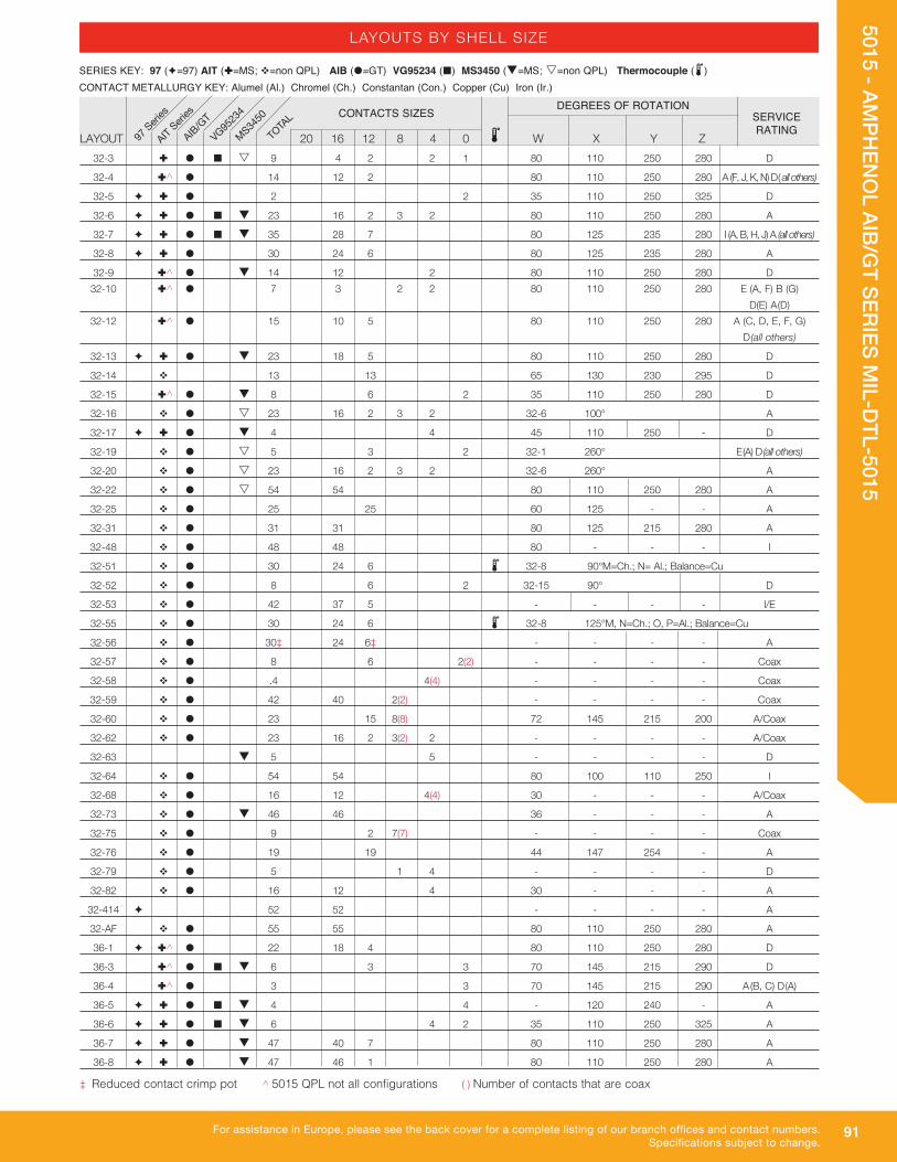
91
5015 - AMPH
ENO
L AIB/GT SERIES M
IL-DTL-5015
For assistance in Europe, please see the back cover for a complete listing of our branch offices and contact numbers.Specifications subject to change.
LAYOUT 20 16 12 8 4 0 W X Y Z
32-3 Ì � ¢ s 9 4 2 2 1 80 110 250 280 D
32-4 Ì^ � 14 12 2 80 110 250 280 A (F, J, K, N) D( all others)
32-5 è Ì � 2 2 35 110 250 325 D
32-6 è Ì � ¢ q 23 16 2 3 2 80 110 250 280 A
32-7 è Ì � ¢ q 35 28 7 80 125 235 280 I (A, B, H, J) A (all others)
32-8 è Ì � 30 24 6 80 125 235 280 A
32-9 Ì^ � q 14 12 2 80 110 250 280 D 32-10 Ì^ � 7 3 2 2 80 110 250 280 E (A, F) B (G) D(E) A(D) 32-12 Ì^ � 15 10 5 80 110 250 280 A (C, D, E, F, G) D(all others)
32-13 è Ì � q 23 18 5 80 110 250 280 D
32-14 v 13 13 65 130 230 295 D
32-15 Ì^ � q 8 6 2 35 110 250 280 D
32-16 v � s 23 16 2 3 2 32-6 100° A
32-17 è Ì � q 4 4 45 110 250 - D
32-19 v � s 5 3 2 32-1 260° E(A) D(all others)
32-20 v � s 23 16 2 3 2 32-6 260° A
32-22 v � s 54 54 80 110 250 280 A
32-25 v � 25 25 60 125 - - A
32-31 v � 31 31 80 125 215 280 A
32-48 v � 48 48 80 - - - I
32-51 v � 30 24 6 2 32-8 90° M=Ch.; N= Al.; Balance=Cu
32-52 v � 8 6 2 32-15 90° D
32-53 v � 42 37 5 - - - - I/E
32-55 v � 30 24 6 2 32-8 125° M, N=Ch.; O, P=Al.; Balance=Cu
32-56 v � 30‡ 24 6‡ - - - - A
32-57 v � 8 6 2(2) - - - - Coax
32-58 v � .4 4(4) - - - - Coax
32-59 v � 42 40 2(2) - - - - Coax
32-60 v � 23 15 8(8) 72 145 215 200 A/Coax
32-62 v � 23 16 2 3(2) 2 - - - - A/Coax
32-63 q 5 5 - - - - D
32-64 v � 54 54 80 100 110 250 I
32-68 v � 16 12 4(4) 30 - - - A/Coax
32-73 v � q 46 46 36 - - - A
32-75 v � 9 2 7(7) - - - - Coax
32-76 v � 19 19 44 147 254 - A
32-79 v � 5 1 4 - - - - D
32-82 v � 16 12 4 30 - - - A
32-414 è 52 52 - - - - A
32-AF v � 55 55 80 110 250 280 A
36-1 è Ì^ � 22 18 4 80 110 250 280 D
36-3 Ì^ � ¢ q 6 3 3 70 145 215 290 D
36-4 Ì^ � 3 3 70 145 215 290 A(B, C) D(A)
36-5 è Ì � ¢ q 4 4 - 120 240 - A
36-6 è Ì � ¢ q 6 4 2 35 110 250 325 A
36-7 è Ì � q 47 40 7 80 110 250 280 A
36-8 è Ì � q 47 46 1 80 110 250 280 A
DEGREES OF ROTATIONCONTACTS SIZES SERVICE RATING
LAYOUTS BY SHELL SIZE
2 97 Seri
es
AIT Seri
es
AIB/GT
VG9523
4
MS34
50
SERIES KEY: 97 (è=97) AIT (Ì=MS; v=non QPL) AIB (�=GT) VG95234 (¢) MS3450 (q=MS; s=non QPL) Thermocouple (2) CONTACT METALLURGY KEY: Alumel (Al.) Chromel (Ch.) Constantan (Con.) Copper (Cu) Iron (Ir.)
TOTA
L
‡ Reduced contact crimp pot ^ 5015 QPL not all configurations ( ) Number of contacts that are coax

92
5015 - AMPH
ENO
L AIB/GT SERIES M
IL-DTL-5015
For assistance in North America: +1 800.642.8750 for Pricing/Delivery or +1 800.523.0727 Tech Support • www.peigenesis.com • [email protected]
LAYOUT 20 16 12 8 4 0 W X Y Z
36-9 è Ì � q 31 14 14 2 1 80 125 235 280 A
36-10 è Ì � ¢ q 48 48 80 125 235 280 A
36-11 è v � s 48 48 36-10 100° A
36-12 è v � s 48 48 36-10 250° A
36-13 Ì^ � 17 15 2 80 110 250 280 E (N,P,Q) A (all others)
36-14 Ì^ � 16 6 5 5 90 180 270 - D
36-15 è Ì � q 35 35 60 125 245 305 D(M) A (all others)
36-16 v � s 47 40 7 36-7 100° A
36-17 v � s 47 40 7 36-7 250° A
36-18 v � s 31 14 14 2 1 36-9 100° A
36-20 v � 34 30 2 2 - - - - A
36-21 v � s 31 14 14 2 1 36-9 260° A
36-22 v � 22 22 - - - - D
36-51 v � 4 2 2 - 127 - - D
36-52 Ì^ � q 52 52 72 144 216 288 A
36-53 v � s 47 40 7 2 36-7 45° u, v, w=Al.; x, y, z=Ch.; Balance=Cu
36-54 v � 39 31 8 - - - - A
36-55 v � 39‡ 31 8‡ - - - - A
36-56 v � s 48 48 2 36-10 A, C, E, G, L, J, H, P, R, T, V, X, Z, b, d, f, h, k, q,
n, m, u, w, y=Con.; Balance=Cu
36-59 v � 53‡ 50 3‡ - - - - A
36-60 v � 47‡ 40 7‡ - - - - A
36-61 v � s 35 35 2 36-15 A, C, E, J, K, L, M, N, P, R, T, V, f, X, Y, h, j,
c=Con.; Balance=Cu
36-62 v � s 48 48 2 36-10 A, C, E=Al.; B, D, F=Ch.; Balance=Cu
36-64 v � 4 4(4) - - - - Coax
36-65 v � 4 4(4) - - - - Coax
36-66 s 56 52 4 110 250 260 280 A
36-71 v � 53 50 3 - - - - A
36-73 v � 7 7(7) 81 279 - - Coax
36-74 v � 44 43 1(1) - - - - A
36-75 v � 48‡ 48‡ - - - - A
36-76 v � 47 47 - - - - A
36-77 v � 7 7 81 279 - - D
36-78 v � 14 2 12 35 106 254 325 A
36-79 v � 20 20 30 110 250 330 A
36-80 v � 20‡ 20‡ 30 110 250 330 A
36-82 v � s 52 52 2 36-52 v, g=Ir.; p, y, c=Con. x=Ch.; Balance=Cu
36-83 v � 7 7(7) 81 279 - - Coax
36-85 v � 35‡ 35‡ - - - - A/D
36-403 è 52 52 - - - - A
36-57 v � s 47 46 1 2 36-8 W=Al.; f=Ch.; Balance=Cu
36-58 v � s 35 35 2 36-15 H=Al.; G=Ch.; Balance=Cu 36-AF v � 48 48 65 - - - A 40-1 Ì � q 30 24 6 65 130 235 300 D 40-2 s 23 23 80 110 250 280 D 40-3 s 23 18 4 1 80 110 250 280 D
LAYOUTS BY SHELL SIZE
2
DEGREES OF ROTATIONCONTACTS SIZES
SERVICE RATING 97
Series
AIT Seri
es
AIB/GT
VG9523
4
MS34
50
TOTA
L
SERIES KEY: 97 (è=97) AIT (Ì=MS; v=non QPL) AIB (�=GT) VG95234 (¢) MS3450 (q=MS; s=non QPL) Thermocouple (2) CONTACT METALLURGY KEY: Alumel (Al.) Chromel (Ch.) Constantan (Con.) Copper (Cu) Iron (Ir.)
‡ Reduced contact crimp pot ^ 5015 QPL not all configurations ( ) Number of contacts that are coax

93
5015 - AMPH
ENO
L AIB/GT SERIES M
IL-DTL-5015
For assistance in Europe, please see the back cover for a complete listing of our branch offices and contact numbers.Specifications subject to change.
LAYOUT 20 16 12 8 4 0 W X Y Z
40-4 s 23 16 2 3 2 80 110 250 280 D
40-5## s 15 6 4 2 3 80 110 250 280 A
40-5 v � 5 5 33 - - 270 A
40-6 s 26 24 1 1 80 110 250 280 D
40-7 s 22 18 2 2 80 110 250 280 P,Q,U,V,W,X = A; Bal.= D
40-9 Ì � q 47 24 22 1 65 125 225 310 A
40-10 Ì^ � 29 16 9 4 65 125 225 310 A
40-35 v � 35 35 70 130 230 290 D
40-53 v � 60 60 80 110 250 280 A
40-56 Ì � q 85 85 72 144 216 288 A
40-57 v � 4 4 30 150 - - E
40-58 v � s 85 85 2 40-56 A, C, E, H, K, M, P, S, U, W, Y, a, c, f, h, j, m, p, r, t, v, x, z,
AB, AD, AF, AJ, AL,AN, AP, AS, AU, AW,
AY, BA, BC, BE, BH, BK, BM, BP, BS, BU=Ir.; Balance=Con.
40-59 v � s 85 85 2 40-56 B=Ch.; C=Con.; Balance=Cu
40-61 v � 59 55 3 1 - - - - A
40-62 Ì � s 60 60 30 130 220 290 A
40-63 v � 61‡ 61‡ - - - - A
40-64 v � 36 20 3 13(13) - - - - Coax
40-66 v � 4 4(4) - - - - Coax
40-67 v � 11 1 10(10) - - - - A/Coax
40-68 v � 21 21 - - - - A
40-70 v � 61 61 - - - - A
40-72 v � 11 1 10(10) - - - - A/Coax
40-73 v � 61 61 - - - - A
40-74 v � 6 1 1(1) 4(4) - - - - A/Coax
40-75 v � 5 1 4 - - - - E
40-77 v � 60 60 2 40-56 55, 60=Ir.; 57, 58, 59=Con.; 56=Ch.; Balance=Cu
40-78 v � 60 60 2 40-53 50 51=Ir.; 27, 28, 29, 31, 32, 34, 36, 37=Con.; 25, 39,
40, 41=Al 43,44,45, 46, 47, 48, 49, 52, 53, 54=Ch.;
Balance=Cu
40-80 v � 11 1 10 72 144 210 288 A
40-81 v � 62‡ 62‡ - - - - A
40-82 v � 62 62 - - - - A
40-85 v � 60‡ 60‡ - - - - A
40-86 v � 4 4(4) - - - - E/Coax
40-87 v � 7 7 37 74 285 322 D
40-AD v � 8 4 4 45 - - - A
40-AG v � 38 38 37 74 285 322 A
40-AT v � 43 18 24 1 80 110 250 280 A
40-AV v � 3 3#2/0 90 180 270 - D
DEGREES OF ROTATIONCONTACTS SIZES SERVICE
RATING
LAYOUTS BY SHELL SIZE
2 97 Seri
es
AIT Seri
es
AIB/GT
VG9523
4
MS34
50
SERIES KEY: 97 (è=97) AIT (Ì=MS; v=non QPL) AIB (�=GT) VG95234 (¢) MS3450 (q=MS; s=non QPL) Thermocouple (2) CONTACT METALLURGY KEY: Alumel (Al.) Chromel (Ch.) Constantan (Con.) Copper (Cu) Iron (Ir.)
TOTA
L
‡ Reduced contact crimp pot ^ 5015 QPL not all configurations ( ) Number of contacts that are coax
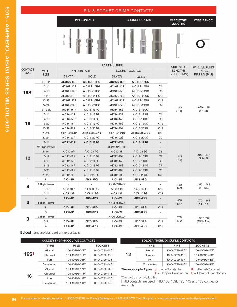
94
5015 - AMPH
ENO
L AIB/GT SERIES M
IL-DTL-5015
For assistance in North America: +1 800.642.8750 for Pricing/Delivery or +1 800.523.0727 Tech Support • www.peigenesis.com • [email protected]
PIN & SOCKET CRIMP CONTACTS
16S 16-18-20 AIC16S-16P AIC16S-16PG AIC16S-16S AIC16S-16SG - 12-14 AIC16S-12P AIC16S-12PG AIC16S-12S AIC16S-12SG C4 14-16 AIC16S-14P AIC16S-14PG AIC16S-14S AIC16S-14SG C3 18-20 AIC16S-20P AIC16S-20PG AIC16S-20S AIC16S-20SG C13 20-22 AIC16S-22P AIC16S-22PG AIC16S-22S AIC16S-22SG C14 22-24 AIC16S-24P AIC16S-24PG AIC16S-24S AIC16S-24SG C2 16 16-18-20 AIC16-16P AIC16-16PG AIC16-16S AIC16-16SG - 12-14 AIC16-12P AIC16-12PG AIC16-12S AIC16-12SG C4 14-16 AIC16-14P AIC16-14PG AIC16-14S AIC16-14SG C3 18-20 AIC16-18P AIC16-18PG AIC16-18S AIC16-18SG C13 20-22 AIC16-20P AIC16-20PG AIC16-20S AIC16-20SG C14 20-24 AIC16-2024P AIC16-2024PG AIC16-2024S AIC16-2024SG C36 22-24 AIC16-22P AIC16-22PG AIC16-22S AIC16-22SG C2 12 12-14 AIC12-12P AIC12-12PG AIC12-12S AIC12-12SG - .312 (7.9) 12 High-Power - - AIC12-12SRAD - - 8-10 AIC12-8P AIC12-8PG AIC12-8S AIC12-8SG C5 10-12 AIC12-10P AIC12-10PG AIC12-10S AIC12-10SG C8 14-16 AIC12-14P AIC12-14PG AIC12-14S AIC12-14SG C9 16-18 AIC12-16P AIC12-16PG AIC12-16S AIC12-16SG C7 18-20 AIC12-18P AIC12-18PG AIC12-18S AIC12-18SG C6 20-22 AIC12-20P AIC12-20PG AIC12-20S AIC12-20SG C40 8 8 AIC8-8P AIC8-8PG AIC8-8S AIC8-8SG - 8 High-Power - - AIC8-8SRAD - - 10-12 AIC8-10P AIC8-10PG AIC8-10S AIC8-10SG C10 12-14 AIC8-12P AIC8-12PG AIC8-12S AIC8-12SG C38 4 4 AIC4-4P AIC4-4PG AIC4-4S AIC4-4SG - 4 High-Power - - AIC4-4SRAD - - 8 AIC4-8P AIC4-8PG AIC4-8S AIC4-8SG C15 0 0 AIC0-0P AIC0-0PG AIC0-0S AIC0-0SG - . 0 High-Power - - AIC0-0SRAD - - 0-2 AIC0-2P AIC0-2PG AIC0-2S AIC0-2SG C11 4 AIC0-4P AIC0-4PG AIC0-4S AIC0-4SG C12
PIN CONTACT SOCKET CONTACT
CONTACT SIZE WIRE
SIZE
PIN CONTACTWIRE SEALING
RANGE INCHES (MM)
WIRE STRIP LENGTHS
INCHES (MM)SOCKET CONTACT
SILVER GOLD SILVER GOLD
WIRE STRIP LENGTHS
PART NUMBER
16S†
16
12
8
4
0
.090 -.118 (2.3-3.0)
.312 (7.9)
.126 - .177 (3.2-4.5)
.563 (14.3)
.150 - .256 (3.8-6.5)
.500 (12.7)
.279 - .366 (7.1 - 9.3)
.750 (19.0)
SOLDER THERMOCOUPLE CONTACTS TYPE PINS SOCKETS 16S Alumel 10-040799-02P* 10-040799-02S* Chromel 10-040799-01P* 10-040799-01S* Iron 10-040799-03P* 10-040799-03S* Constantan 10-040799-04P* 10-040799-04S* 16 Alumel 10-040799-12P* 10-040799-12S* Chromel 10-040799-11P* 10-040799-11S* Iron 10-040799-13P* 10-040799-13S* Constantan 10-040799-14P* 10-040799-14S*
SOLDER THERMOCOUPLE CONTACTS TYPE PINS SOCKETS 12 Alumel 10-040799-42P* 10-040799-42S* Chromel 10-040799-41P* 10-040799-41S* Iron 10-040799-43P* 10-040799-43S* Constantan 10-040799-44P* 10-040799-44S*
16S†
16
12
*Contact us for availability† 16S contacts are used in 8S, 10S, 10SL, 12S, 14S and 16S connector sizes only.
WIRE RANGE
.394 - .539 (10.0 - 13.7)
Bolded items are standard crimp contacts.
.312 (7.9)
••• •
Thermocouple Types: J = Iron-Constantan K = Alumel-Chromel T = Copper-Constantan E = Chromel-Constantan
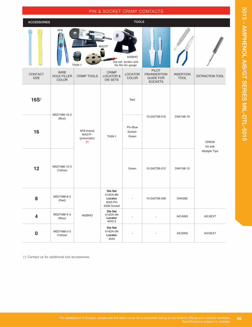
95
5015 - AMPH
ENO
L AIB/GT SERIES M
IL-DTL-5015
For assistance in Europe, please see the back cover for a complete listing of our branch offices and contact numbers.Specifications subject to change.
PIN & SOCKET CRIMP CONTACTS
†† Contact us for additional tool accessories.
AF8
TH29-1Die-set, locator and Go-No-Go gauge
400BHD
WA27F
TOOLSACCESSORIES
CONTACT SIZE
WIRE HOLE FILLER
COLORCRIMP TOOLS
CRIMP LOCATOR &
DIE SETS
LOCATOR COLOR
PILOT PIN/INSERTION
GUIDE FORSOCKETS
INSERTION TOOL EXTRACTION TOOL
16S†
MS27488-16-3 (Blue)
AF8-(hand) WA27F-
(pneumatic) ††
TH29-1
Red
10-242758-016 DAK168-16
DRK59 Kit with
Multiple Tips
16Pin-Blue Socket-Green
12 MS27488-12-3 (Yellow) Green 10-242758-012 DAK168-12
8 MS27488-8-3 (Red)
400BHD
Die Set 414DA-8N Locator 4025-Pin
4026-Socket
- 10-242758-008 DAK282
4 MS27488-4-3 (Blue)
Die Set 414DA-4N Locator 4043-2
- - AIC4INS AIC4EXT
0 MS27488-0-3 (Yellow)
Die Set 414DA-0N Locator
4042
- - AIC0INS AIC0EXT

96
5015 - AMPH
ENO
L AIB/GT SERIES M
IL-DTL-5015
For assistance in North America: +1 800.642.8750 for Pricing/Delivery or +1 800.523.0727 Tech Support • www.peigenesis.com • [email protected]
PIN & SOCKET COAX CONTACTS
-
- -
-
21-33033-8
4
8
COAX CONTACT
SIZE
COAX WIRE SIZE
PINSWIRE SEALING
RANGE INCHES (mm)
WIRE STRIP LENGTHS
INCHES (mm)
SOCKETS
SILVER GOLD SILVER GOLD
WIRE HOLE FILLER
MIN. MAX.
PIN CONTACT ACCESS-ORIES
RG140/U RG302/U
RG55B/U RG142A/U RG142B/U RG223/U
21-33060-10()
21-33060-11()
RG59B/U RG62A/U RG62B/U RG210/U
RG212/U
0.279 (7.1)
0.366 (9.3)
21-33034-3(1)
21-33014-3(5) 21-33016-1(3) 21-33130-3 () 21-33064-20()
31-33060-12() 21-33059-12()
Blue 10-405996-4
0.150 (3.8)
0.256 (6.5)
White 10-405996-8
( ) Various platings available. Availability of coax contacts varies widely. Contact us for details.All dimensions in inches (millimeters in parenthesis)
21-33014-1(5) 21-33016-5(3) 21-33130-2()
21-33034-2(1)21-33033-2(1) 21-33048-2()
21-33013-1(5) 21-33047-2() 21-33015-5(3) 21-33129-2()
21-33034-5(1)
21-33033-3(1)
21-33014-5(5) 21-33016-2(3) 21-33130-5() 21-33064-21()
21-33033-5(1)
21-33013-5(5) 21-33015-2(3) 21-33129-3() 21-33063-21()
21-33013-(6) 21-33047-3() 21-33129-6()
RG58C/U RG141A/U RG303/U
RG59B/U RG62A/U RG62B/U RG210/U
RG161/U RG174A/U RG179B/U RG187A/U RG188A/U RG316/U
RG180B/U RG195A/U
21-33034-121-33014-2121-33048-1()21-33130-1()
21-33014-22
21-33033-1
21-33013-2121-33047-1()21-33129-1 ()
21-33013-22
0.126(3.2)
0.177(4.5)
Yellow 10-405996-12
21-33013-3(5) 21-33015-1(3) 21-33129-3()
21-33063-20()
21-33014-6(5) 21-33048-3() 21-33130-6()
21-33033-621-33034-6
21-33034-8
RG161/U RG174A/U RG179B/U RG187A/U RG188A/U
RG316/U
21-33014-8(5) 21-33033-8 21-33130-8()
21-33013-8(5) 21-33129-8()
RG178B/U RG196A/U
21-33059-10()
21-33059-11()
21-33013-5(5) 21-33129-4()
21-33033-421-33014-5(5) 21-33130-4()21-33034-4
RG55B/U RG142A/U RG142B/U RG223/U
Contact us for details
Contact us for details
Contact us for details
- -
SOCKET CONTACT
PART NUMBER
WIRE STRIP LENGTH
WIRE RANGE
12
--
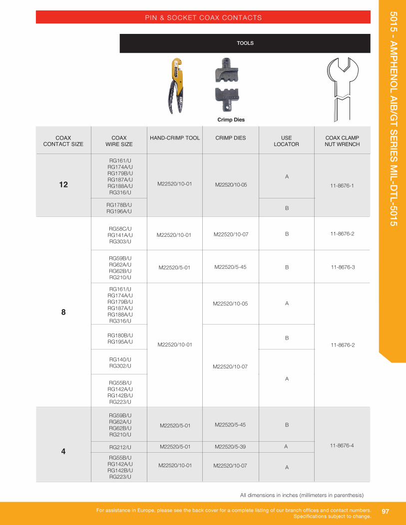
97
5015 - AMPH
ENO
L AIB/GT SERIES M
IL-DTL-5015
For assistance in Europe, please see the back cover for a complete listing of our branch offices and contact numbers.Specifications subject to change.
PIN & SOCKET COAX CONTACTS
M22520/5-01 M22520/5-39 A
TOOLS
B
M22520/10-07M22520/10-01 B
M22520/5-45M22520/5-01
AM22520/10-05
M22520/10-01
B
M22520/10-07
A
BM22520/5-01 M22520/5-45
M22520/10-01 M22520/10-07
RG140/U RG302/U
RG55B/U RG142A/U RG142B/U RG223/U
RG59B/U RG62A/U RG62B/U RG210/U
RG212/U
RG58C/U RG141A/U RG303/U
RG59B/U RG62A/U RG62B/U RG210/U
RG161/U RG174A/U RG179B/U RG187A/U RG188A/U RG316/U
RG180B/U RG195A/U
RG161/U RG174A/U RG179B/U RG187A/U RG188A/U RG316/U
RG178B/U RG196A/U
RG55B/U RG142A/U RG142B/U RG223/U
A
B
11-8676-1
11-8676-2
M22520/10-05M22520/10-01
11-8676-3
11-8676-2
11-8676-44
8
12
Crimp Dies
COAX CONTACT SIZE
COAX WIRE SIZE
HAND-CRIMP TOOL CRIMP DIES USE LOCATOR
COAX CLAMP NUT WRENCH
All dimensions in inches (millimeters in parenthesis)
B
A
AM22520/5-01 M22520/5-39
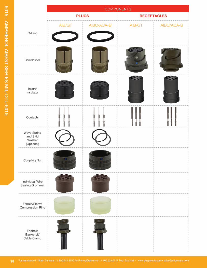
98
5015 - AMPH
ENO
L AIB/GT SERIES M
IL-DTL-5015
For assistance in North America: +1 800.642.8750 for Pricing/Delivery or +1 800.523.0727 Tech Support • www.peigenesis.com • [email protected]
AIB/GT AIBC/ACA-B
PLUGS RECEPTACLES
AIB/GT AIBC/ACA-B
COMPONENTS
Ferrule/Sleeve Compression Ring
O-Ring
Barrel/Shell
Insert/ Insulator
Contacts
Wave Spring and Skid Washer
(Optional)
Coupling Nut
Individual Wire Sealing Grommet
Endbell/ Backshell/
Cable Clamp

99
5015 - AMPH
ENO
L AIB/GT SERIES M
IL-DTL-5015
For assistance in Europe, please see the back cover for a complete listing of our branch offices and contact numbers.Specifications subject to change.
DIMENSIONS
All dimensions in inches (millimeters in parenthesis)
PRINTED CIRCUIT CONTACTS
10SL .188 .567 (4.78) (14.40) 14S .188 .567 (4.78) (14.40) 16S .188 .567 (4.78) (14.40) 16 .188 .622 (4.78) (15.80) 18 .188 .622 (4.78) (15.80) 20 .188 .622 (4.78) (15.80) 22 .188 .622 (4.78) (15.80) 24 .188 .622 (4.78) (15.80) 28 .188 .657 (4.78) (16.69) 32 .188 .720 (4.78) (18.29) 36 .188 .720 (4.78) (18.29) 40 .188 .720 (4.78) (18.29)
SHELL SIZE
H SERIES
S X 12 .134 .070
(3.4) (1.78)
16 .063 .030
(1.6) (0.76)
CONTACT
SIZE D
P
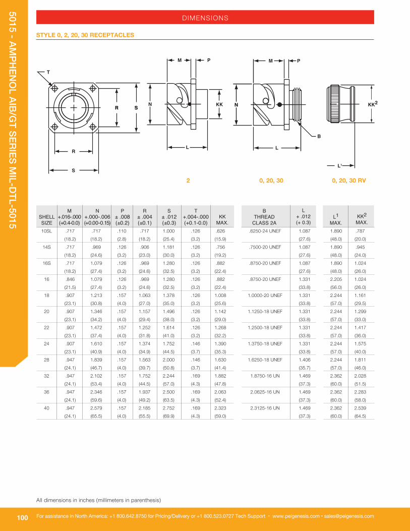
100
5015 - AMPH
ENO
L AIB/GT SERIES M
IL-DTL-5015
For assistance in North America: +1 800.642.8750 for Pricing/Delivery or +1 800.523.0727 Tech Support • www.peigenesis.com • [email protected]
DIMENSIONS
STYLE 0, 2, 20, 30 RECEPTACLES
R
R S
S
T
R S N
M
N
P
B
L
L1
KK2
.6250-24 UNEF 1.087
(27.6)
.7500-20 UNEF 1.087
(27.6)
.8750-20 UNEF 1.087
(27.6)
.8750-20 UNEF 1.331
(33.8)
1.0000-20 UNEF 1.331
(33.8)
1.1250-18 UNEF 1.331
(33.8)
1.2500-18 UNEF 1.331
(33.8)
1.3750-18 UNEF 1.331
(33.8)
1.6250-18 UNEF 1.406
(35.7)
1.8750-16 UN 1.469
(37.3)
2.0625-16 UN 1.469
(37.3)
2.3125-16 UN 1.469
(37.3)
BTHREAD
CLASS 2A
L+ .012(+ 0.3)
10SL .717 .717 .110 .717 1.000 .126 .626
(18.2) (18.2) (2.8) (18.2) (25.4) (3.2) (15.9)
14S .717 .969 .126 .906 1.181 .126 .756
(18.2) (24.6) (3.2) (23.0) (30.0) (3.2) (19.2)
16S .717 1.079 .126 .969 1.280 .126 .882
(18.2) (27.4) (3.2) (24.6) (32.5) (3.2) (22.4)
16 .846 1.079 .126 .969 1.280 .126 .882
(21.5) (27.4) (3.2) (24.6) (32.5) (3.2) (22.4)
18 .907 1.213 .157 1.063 1.378 .126 1.008
(23.1) (30.8) (4.0) (27.0) (35.0) (3.2) (25.6)
20 .907 1.346 .157 1.157 1.496 .126 1.142
(23.1) (34.2) (4.0) (29.4) (38.0) (3.2) (29.0)
22 .907 1.472 .157 1.252 1.614 .126 1.268
(23.1) (37.4) (4.0) (31.8) (41.0) (3.2) (32.2)
24 .907 1.610 .157 1.374 1.752 .146 1.390
(23.1) (40.9) (4.0) (34.9) (44.5) (3.7) (35.3)
28 .947 1.839 .157 1.563 2.000 .146 1.630
(24.1) (46.7) (4.0) (39.7) (50.8) (3.7) (41.4)
32 .947 2.102 .157 1.752 2.244 .169 1.882
(24.1) (53.4) (4.0) (44.5) (57.0) (4.3) (47.8)
36 .947 2.346 .157 1.937 2.500 .169 2.063
(24.1) (59.6) (4.0) (49.2) (63.5) (4.3) (52.4)
40 .947 2.579 .157 2.185 2.752 .169 2.323
(24.1) (65.5) (4.0) (55.5) (69.9) (4.3) (59.0)
SHELL SIZE
M +.016-.000 (+0.4-0.0)
N +.000-.006 (+0.00-0.15)
P ± .008 (±0.2)
R ± .004 (±0.1)
S ± .012 (±0.3)
T +.004-.000 (+0.1-0.0)
KK
MAX. 1.890 .787
(48.0) (20.0)
1.890 .945
(48.0) (24.0)
1.890 1.024
(48.0) (26.0)
2.205 1.024
(56.0) (26.0)
2.244 1.161
(57.0) (29.5)
2.244 1.299
(57.0) (33.0)
2.244 1.417
(57.0) (36.0)
2.244 1.575
(57.0) (40.0)
2.244 1.811
(57.0) (46.0)
2.362 2.028
(60.0) (51.5)
2.362 2.283
(60.0) (58.0)
2.362 2.539
(60.0) (64.5)
L1
MAX.
KK2 MAX.
0, 20, 30
N
M P
KK
L
2 0, 20, 30 RV
All dimensions in inches (millimeters in parenthesis)
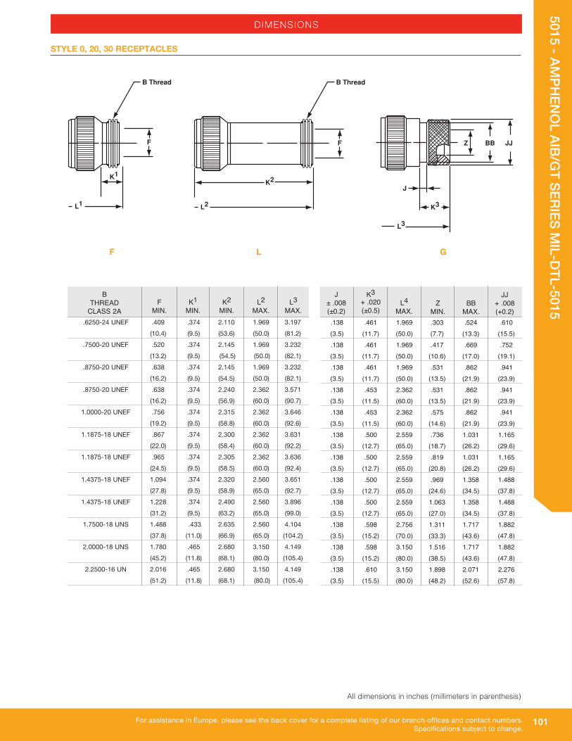
101
5015 - AMPH
ENO
L AIB/GT SERIES M
IL-DTL-5015
For assistance in Europe, please see the back cover for a complete listing of our branch offices and contact numbers.Specifications subject to change.
DIMENSIONS
STYLE 0, 20, 30 RECEPTACLES
L3
JJBBZ
J
K3
.6250-24 UNEF .409 .374 2.110 1.969 3.197
(10.4) (9.5) (53.6) (50.0) (81.2)
.7500-20 UNEF .520 .374 2.145 1.969 3.232
(13.2) (9.5) (54.5) (50.0) (82.1)
.8750-20 UNEF .638 .374 2.145 1.969 3.232
(16.2) (9.5) (54.5) (50.0) (82.1)
.8750-20 UNEF .638 .374 2.240 2.362 3.571
(16.2) (9.5) (56.9) (60.0) (90.7)
1.0000-20 UNEF .756 .374 2.315 2.362 3.646
(19.2) (9.5) (58.8) (60.0) (92.6)
1.1875-18 UNEF .867 .374 2.300 2.362 3.631
(22.0) (9.5) (58.4) (60.0) (92.2)
1.1875-18 UNEF .965 .374 2.305 2.362 3.636
(24.5) (9.5) (58.5) (60.0) (92.4)
1.4375-18 UNEF 1.094 .374 2.320 2.560 3.651
(27.8) (9.5) (58.9) (65.0) (92.7)
1.4375-18 UNEF 1.228 .374 2.490 2.560 3.896
(31.2) (9.5) (63.2) (65.0) (99.0)
1.7500-18 UNS 1.488 .433 2.635 2.560 4.104
(37.8) (11.0) (66.9) (65.0) (104.2)
2.0000-18 UNS 1.780 .465 2.680 3.150 4.149
(45.2) (11.8) (68.1) (80.0) (105.4)
2.2500-16 UN 2.016 .465 2.680 3.150 4.149
(51.2) (11.8) (68.1) (80.0) (105.4)
BTHREAD
CLASS 2A
F
MIN.
K1
MIN.
L2
MAX.
L3
MAX. .138 .461 1.969 .303 .524 .610 (3.5) (11.7) (50.0) (7.7) (13.3) (15.5) .138 .461 1.969 .417 .669 .752 (3.5) (11.7) (50.0) (10.6) (17.0) (19.1) .138 .461 1.969 .531 .862 .941 (3.5) (11.7) (50.0) (13.5) (21.9) (23.9) .138 .453 2.362 .531 .862 .941 (3.5) (11.5) (60.0) (13.5) (21.9) (23.9) .138 .453 2.362 .575 .862 .941 (3.5) (11.5) (60.0) (14.6) (21.9) (23.9) .138 .500 2.559 .736 1.031 1.165 (3.5) (12.7) (65.0) (18.7) (26.2) (29.6) .138 .500 2.559 .819 1.031 1.165 (3.5) (12.7) (65.0) (20.8) (26.2) (29.6) .138 .500 2.559 .969 1.358 1.488 (3.5) (12.7) (65.0) (24.6) (34.5) (37.8) .138 .500 2.559 1.063 1.358 1.488 (3.5) (12.7) (65.0) (27.0) (34.5) (37.8) .138 .598 2.756 1.311 1.717 1.882 (3.5) (15.2) (70.0) (33.3) (43.6) (47.8) .138 .598 3.150 1.516 1.717 1.882 (3.5) (15.2) (80.0) (38.5) (43.6) (47.8) .138 .610 3.150 1.898 2.071 2.276 (3.5) (15.5) (80.0) (48.2) (52.6) (57.8)
J ± .008 (±0.2)
K3 + .020 (±0.5)
L4
MAX.
Z
MIN.
BB
MAX.
JJ + .008 (+0.2)
F L G
L1
B Thread
F
K1
L2
B Thread
K2
F
K2
MIN.
All dimensions in inches (millimeters in parenthesis)

102
5015 - AMPH
ENO
L AIB/GT SERIES M
IL-DTL-5015
For assistance in North America: +1 800.642.8750 for Pricing/Delivery or +1 800.523.0727 Tech Support • www.peigenesis.com • [email protected]
DIMENSIONS
STYLE 1 CABLE RECEPTACLE
Q
S
N
M P
B
LL
KK
.6250-24 UNEF 1.087 (27.6) .7500-20 UNEF 1.087 (27.6) .8750-20 UNEF 1.087 (27.6) .8750-20 UNEF 1.331 (33.8) 1.0000-20 UNEF 1.331 (33.8) 1.1250-18 UNEF 1.331 (33.8) 1.2500-18 UNEF 1.331 (33.8) 1.3750-18 UNEF 1.331 (33.8) 1.6250-18 UNEF 1.406 (35.7) 1.8750-16 UN 1.469 (37.3) 2.0625-16 UN 1.469 (37.3) 2.3125-16 UN 1.469 (37.3)
BTHREAD
CLASS 2A
L+ .012(+ 0.3)
10SL .717 .717 .110 .811 .992 (18.2) (18.2) (2.8) (20.6) (25.2) 14S .717 .969 .126 1.000 1.173 (18.2) (24.6) (3.2) (25.4) (29.8) 16S .717 1.079 .126 1.126 1.272 (18.2) (27.4) (3.2) (28.6) (32.3) 16 .846 1.079 .126 1.126 1.272 (21.5) (27.4) (3.2) (28.6) (32.3) 18 .907 1.213 .157 1.248 1.370 (23.0) (30.8) (4.0) (31.7) (34.8) 20 .907 1.346 .157 1.374 1.488 (23.0) (34.2) (4.0) (34.9) (37.8) 22 .907 1.472 .157 1.500 1.618 (23.0) (37.4) (4.0) (38.1) (41.1) 24 .907 1.610 .157 1.626 1.756 (23.0) (40.9) (4.0) (41.3) (44.6) 28 .947 1.839 .157 1.874 2.004 (24.1) (46.7) (4.0) (47.6) (50.9) 32 .947 2.102 .157 2.126 2.248 (24.1) (53.4) (4.0) (54.0) (57.1) 36 .947 2.346 .157 2.386 2.504 (24.1) (59.6) (4.0) (60.6) (63.6) 40 .947 2.579 .157 2.618 2.756 (24.1) (65.5) (4.0) (66.5) (70.0)
SHELL SIZE
M +.016 -.000 (+0.4 - 0.0)
N +.000 -.006 (+0.00-0.15)
P ± .008 (±0.2)
Q ± .008 (±0.2)
S
MAX. 1.890 .787 (48.0) (20.0) 1.890 .945 (48.0) (24.0) 1.890 1.024 (48.0) (26.0) 2.205 1.024 (56.0) (26.0) 2.244 1.161 (57.0) (29.5) 2.244 1.299 (57.0) (33.0) 2.244 1.417 (57.0) (36.0) 2.244 1.575 (57.0) (40.0) 2.244 1.811 (57.0) (46.0) 2.362 2.028 (60.0) (51.5) 2.362 2.283 (60.0) (58.0) 2.362 2.539 (60.0) (64.5)
L1
MAX.
KK
MAX.
RV
All dimensions in inches (millimeters in parenthesis)

103
5015 - AMPH
ENO
L AIB/GT SERIES M
IL-DTL-5015
For assistance in Europe, please see the back cover for a complete listing of our branch offices and contact numbers.Specifications subject to change.
DIMENSIONS
STYLE 1 CABLE RECEPTACLE
L
JJBBZ
J
K3
.138 .461 1.969 .303 .524 .610 (3.5) (11.7) (50.0) (7.7) (13.3) (15.5) .138 .461 1.969 .417 .669 .752 (3.5) (11.7) (50.0) (10.6) (17.0) (19.1) .138 .461 1.969 .531 .862 .941 (3.5) (11.7) (50.0) (13.5) (21.9) (23.9) .138 .453 2.362 .531 .862 .941 (3.5) (11.5) (60.0) (13.5) (21.9) (23.9) .138 .453 2.362 .575 .862 .941 (3.5) (11.5) (60.0) (14.6) (21.9) (23.9) .138 .500 2.559 .736 1.031 1.165 (3.5) (12.7) (65.0) (18.7) (26.2) (29.6) .138 .500 2.559 .819 1.031 1.165 (3.5) (12.7) (65.0) (20.8) (26.2) (29.6) .138 .500 2.559 .969 1.358 1.488 (3.5) (12.7) (65.0) (24.6) (34.5) (37.8) .138 .500 2.559 1.063 1.358 1.488 (3.5) (12.7) (65.0) (27.0) (34.5) (37.8) .138 .598 2.756 1.311 1.717 1.882 (3.5) (15.2) (70.0) (33.3) (43.6) (47.8) .138 .598 3.150 1.516 1.717 1.882 (3.5) (15.2) (80.0) (38.5) (43.6) (47.8) .138 .610 3.150 1.898 2.071 2.276 (3.5) (15.5) (80.0) (48.2) (52.6) (57.8)
J ± .008 (±0.2)
K3 + .020 (±0.5)
L4
MAX.
Z
MIN.
BB
MAX.
JJ + .008 (+0.2)
.6250-24 UNEF .409 .374 2.110 1.969 3.197 (10.4) (9.5) (53.6) (50.0) (81.2) .7500-20 UNEF .520 .374 2.145 1.969 3.232 (13.2) (9.5) (54.5) (50.0) (82.1) .8750-20 UNEF .638 .374 2.145 1.969 3.232 (16.2) (9.5) (54.5) (50.0) (82.1) .8750-20 UNEF .638 .374 2.240 2.362 3.571 (16.2) (9.5) (56.9) (60.0) (90.7) 1.0000-20 UNEF .756 .374 2.315 2.362 3.646 (19.2) (9.5) (58.8) (60.0) (92.6) 1.1875-18 UNEF .867 .374 2.300 2.362 3.631 (22.0) (9.5) (58.4) (60.0) (92.2) 1.1875-18 UNEF .965 .374 2.305 2.362 3.636 (24.5) (9.5) (58.5) (60.0) (92.4) 1.4375-18 UNEF 1.094 .374 2.320 2.560 3.651 (27.8) (9.5) (58.9) (65.0) (92.7) 1.4375-18 UNEF 1.228 .374 2.490 2.560 3.896 (31.2) (9.5) (63.2) (65.0) (99.0) 1.7500-18 UNS 1.488 .433 2.635 2.560 4.104 (37.8) (11.0) (66.9) (65.0) (104.2) 2.0000-18 UNS 1.780 .465 2.680 3.150 4.149 (45.2) (11.8) (68.1) (80.0) (105.4) 2.2500-16 UN 2.016 .465 2.680 3.150 4.149 (51.2) (11.8) (68.1) (80.0) (105.4)
BTHREAD
CLASS 2A
F
MIN.
K1
MIN.
L3
MAX.
L2
MAX.
G
L1
B Thread
F
K1
F
L2
B Thread
K2
F
L
K2
MAX.
All dimensions in inches (millimeters in parenthesis)

104
5015 - AMPH
ENO
L AIB/GT SERIES M
IL-DTL-5015
For assistance in North America: +1 800.642.8750 for Pricing/Delivery or +1 800.523.0727 Tech Support • www.peigenesis.com • [email protected]
STYLE 4 RUBBER-COVERED PLUGS
B
L
L
KK
.6250-24 UNEF 1.087 (27.6) 1.0000-20 UNEF 1.331 (33.8) 1.1250-18 UNEF 1.331 (33.8) 1.2500-18 UNEF 1.331 (33.8) 1.3750-18 UNEF 1.331 (33.8) 1.6250-18 UNEF 1.406 (35.7) 1.8750-16 UN 1.469 (37.3) 2.0625-16 UN 1.469 (37.3) 2.3125-16 UN 1.469 (37.3)
BTHREAD
CLASS 2A
L+ .012(+ 0.3)
SHELL SIZE
Q
MAX.S
MAX. 1.417 .787 (36.0) (20.0) 1.929 1.161 (49.0) (29.5) 1.969 1.299 (50.0) (33.0) 1.969 1.417 (50.0) (36.0) 2.008 1.575 (51.0) (40.0) 2.008 1.811 (51.0) (46.0) 2.087 2.028 (53.0) (51.5) 2.106 2.283 (53.5) (58.0) 2.126 2.539 (54.0) (64.5)
L1
MAX.
KK
MAX.
Q
S
10SL 1.319 1.122 (33.5) (28.5) 18 1.929 1.713 (49.0) (43.5) 20 2.028 1.811 (51.5) (46.0) 22 2.224 1.988 (56.5) (50.5) 24 2.362 2.126 (60.0) (54.0) 28 2.638 2.402 (67.0) (61.0) 32 2.992 2.661 (76.0) (67.6) 36 3.240 2.925 (82.3) (74.3) 40 3.465 3.150 (88.0) (80.0)
DIMENSIONS
All dimensions in inches (millimeters in parenthesis)
RV
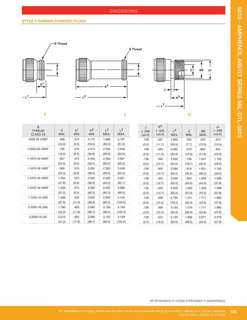
105
5015 - AMPH
ENO
L AIB/GT SERIES M
IL-DTL-5015
For assistance in Europe, please see the back cover for a complete listing of our branch offices and contact numbers.Specifications subject to change.
STYLE 4 RUBBER-COVERED PLUGS
L
JJBBZ
J
K3
3
.138 .461 1.969 .303 .524 .610 (3.5) (11.7) (50.0) (7.7) (13.3) (15.5) .138 .453 2.362 .575 .862 .941 (3.5) (11.5) (60.0) (14.6) (21.9) (23.9) .138 .500 2.559 .736 1.031 1.165 (3.5) (12.7) (65.0) (18.7) (26.2) (29.6). .138 .500 2.559 .819 1.031 1.165 (3.5) (12.7) (65.0) (20.8) (26.2) (29.6) .138 .500 2.559 .969 1.358 1.488 (3.5) (12.7) (65.0) (24.6) (34.5) (37.8). .138 .500 2.559 1.063 1.358 1.488 (3.5) (12.7) (65.0) (27.0) (34.5) (37.8) .138 .598 2.756 1.311 1.717 1.882 (3.5) (15.2) (70.0) (33.3) (43.6) (47.8) .138 .598 3.150 1.516 1.717 1.882 (3.5) (15.2) (80.0) (38.5) (43.6) (47.8) .138 .610 3.150 1.898 2.071 2.276 (3.5) (15.5) (80.0) (48.2) (52.6) (57.8)
J ± .008 (±0.2)
K3 + .020 (±0.5)
L4
MAX.
Z
MIN.
BB
MAX. .6250-24 UNEF .409 .374 2.110 1.969 3.197 (10.4) (9.5) (53.6) (50.0) (81.2) 1.0000-20 UNEF .756 .374 2.315 2.362 3.646 (19.2) (9.5) (58.8) (60.0) (92.6) 1.1875-18 UNEF .867 .374 2.300 2.362 3.631 (22.0) (9.5) (58.4) (60.0) (92.2) 1.1875-18 UNEF .965 .374 2.305 2.362 3.636 (24.5) (9.5) (58.5) (60.0) (92.4) 1.4375-18 UNEF 1.094 .374 2.320 2.560 3.651 (27.8) (9.5) (58.9) (65.0) (92.7) 1.4375-18 UNEF 1.228 .374 2.490 2.560 3.896 (31.2) (9.5) (63.2) (65.0) (99.0) 1.7500-18 UNS 1.488 .433 2.635 2.560 4.104 (37.8) (11.0) (66.9) (65.0) (104.2) 2.0000-18 UNS 1.780 .465 2.680 3.150 4.149 (45.2) (11.8) (68.1) (80.0) (105.4) 2.2500-16 UN 2.016 .465 2.680 3.150 4.149 (51.2) (11.8) (68.1) (80.0) (105.4)
BTHREAD
CLASS 2A
F
MIN.
K1
MIN.
L2
MAX.
L3
MAX.
DIMENSIONS
JJ + .008 (+0.2)
L1
B Thread
F
K1
L2
B Thread
K2
F
K2
MIN.
All dimensions in inches (millimeters in parenthesis)
GLF

106
5015 - AMPH
ENO
L AIB/GT SERIES M
IL-DTL-5015
For assistance in North America: +1 800.642.8750 for Pricing/Delivery or +1 800.523.0727 Tech Support • www.peigenesis.com • [email protected]
DIMENSIONS
STYLE 6, 6HD PLUGS
Q1 Q2
B
L
L
KK
.6250-24 UNEF 1.087 (27.6) .7500-20 UNEF 1.087 (27.6) .8750-20 UNEF 1.087 (27.6) .8750-20 UNEF 1.331 (33.8) 1.0000-20 UNEF 1.331 (33.8) 1.1250-18 UNEF 1.331 (33.8) 1.2500-18 UNEF 1.331 (33.8) 1.3750-18 UNEF 1.331 (33.8) 1.6250-18 UNEF 1.406 (35.7) 1.8750-16 UN 1.469 (37.3) 2.0625-16 UN 1.469 (37.3) 2.3125-16 UN 1.469 (37.3)
BTHREAD
CLASS 2A
L+ .012(+ 0.3)
10SL .898 1.007 (22.8) (25.5) 14S 1.150 1.259 (29.2) (31.9) 16S 1.260 1.410 (32.0) (35.8) 16 1.260 1.410 (32.0) (35.8) 18 1.437 1.547 (36.5) (39.2) 20 1.571 1.681 (39.9) (42.6) 22 1.697 1.847 (43.1) (46.9) 24 1.835 1.965 (46.6) (49.9) 28 2.102 2.222 (53.4) (56.4) 32 2.366 2.482 (60.1) (63.0) 36 2.610 2.721 (66.3) (69.1) 40 2.850 2.953 (72.4) (75.0)
SHELL SIZE
Q1
MAX.
Q2
MAX. 1.417 .787 (36.0) (20.0) 1.437 .945 (36.5) (24.0) 1.437 1.024 (36.5) (26.0) 1.929 1.024 (49.0) (26.0) 1.929 1.161 (49.0) (29.5) 1.969 1.299 (50.0) (33.0) 1.969 1.417 (50.0) (36.0) 2.008 1.543 (51.0) (39.2) 2.008 1.811 (51.0) (46.0) 2.087 2.028 (53.0) (51.5) 2.106 2.283 (53.5) (58.0) 2.126 2.539 (54.0) (64.5)
L1
MAX.
KK
MAX.
6 RV6HD
All dimensions in inches (millimeters in parenthesis)

107
5015 - AMPH
ENO
L AIB/GT SERIES M
IL-DTL-5015
For assistance in Europe, please see the back cover for a complete listing of our branch offices and contact numbers.Specifications subject to change.
DIMENSIONS
STYLE 6, 6HD PLUGS
L
JJBBZ
J
K3
3
.138 .461 1.969 .303 .524 .610 (3.5) (11.7) (50.0) (7.7) (13.3) (15.5) .138 .461 1.969 .417 .669 .752 (3.5) (11.7) (50.0) (10.6) (17.0) (19.1) .138 .461 1.969 .531 .862 .941 (3.5) (11.7) (50.0) (13.5) (21.9) (23.9) .138 .453 2.362 .531 .862 .941 (3.5) (11.5) (60.0) (13.5) (21.9) (23.9) .138 .453 2.362 .575 .862 .941 (3.5) (11.5) (60.0) (14.6) (21.9) (23.9) .138 .500 2.559 .736 1.031 1.165 (3.5) (12.7) (65.0) (18.7) (26.2) (29.6) .138 .500 2.559 .819 1.031 1.165 (3.5) (12.7) (65.0) (20.8) (26.2) (29.6) .138 .500 2.559 .969 1.358 1.488 (3.5) (12.7) (65.0) (24.6) (34.5) (37.8) .138 .500 2.559 1.063 1.358 1.488 (3.5) (12.7) (65.0) (27.0) (34.5) (37.8) .138 .598 2.756 1.311 1.717 1.882 (3.5) (15.2) (70.0) (33.3) (43.6) (47.8) .138 .598 3.150 1.516 1.717 1.882 (3.5) (15.2) (80.0) (38.5) (43.6) (47.8) .138 .610 3.150 1.898 2.071 2.276 (3.5) (15.5) (80.0) (48.2) (52.6) (57.8)
J ± .008 (±0.2)
K3 + .020 (±0.5)
L4
MAX.
Z
MIN.
BB
MAX.
JJ + .008 (+0.2)
.6250-24 UNEF .409 .374 2.110 1.969 3.197 (10.4) (9.5) (53.6) (50.0) (81.2) .7500-20 UNEF .520 .374 2.145 1.969 3.232 (13.2) (9.5) (54.5) (50.0) (82.1) .8750-20 UNEF .638 .374 2.145 1.969 3.232 (16.2) (9.5) (54.5) (50.0) (82.1) .8750-20 UNEF .638 .374 2.240 2.362 3.571 (16.2) (9.5) (56.9) (60.0) (90.7) 1.0000-20 UNEF .756 .374 2.315 2.362 3.646 (19.2) (9.5) (58.8) (60.0) (92.6) 1.1875-18 UNEF .867 .374 2.300 2.362 3.631 (22.0) (9.5) (58.4) (60.0) (92.2) 1.1875-18 UNEF .965 .374 2.305 2.362 3.636 (24.5) (9.5) (58.5) (60.0) (92.4) 1.4375-18 UNEF 1.094 .374 2.320 2.560 3.651 (27.8) (9.5) (58.9) (65.0) (92.7) 1.4375-18 UNEF 1.228 .374 2.490 2.560 3.896 (31.2) (9.5) (63.2) (65.0) (99.0) 1.7500-18 UNS 1.488 .433 2.635 2.560 4.104 (37.8) (11.0) (66.9) (65.0) (104.2) 2.0000-18 UNS 1.780 .465 2.680 3.150 4.149 (45.2) (11.8) (68.1) (80.0) (105.4) 2.2500-16 UN 2.016 .465 2.680 3.150 4.149 (51.2) (11.8) (68.1) (80.0) (105.4)
BTHREAD
CLASS 2A
F
MIN.
K1
MIN.
K2
MIN.
L2
MAX.
L3
MAX.
L1
B Thread
F
K1
L2
B Thread
K2
F
All dimensions in inches (millimeters in parenthesis)
GLF

108
5015 - AMPH
ENO
L AIB/GT SERIES M
IL-DTL-5015
For assistance in North America: +1 800.642.8750 for Pricing/Delivery or +1 800.523.0727 Tech Support • www.peigenesis.com • [email protected]
DIMENSIONS
PLUG STYLE 6, 6HD RIGHT ANGLE
J
L
F
B
Q1Q2
10SL .898 1.007 (22.8) (25.5) 14S 1.150 1.259 (29.2) (31.9) 16S 1.260 1.410 (32.0) (35.8) 16 1.260 1.410 (32.0) (35.8) 18 1.437 1.547 (36.5) (39.2) 20 1.571 1.681 (39.9) (42.6) 22 1.697 1.847 (43.1) (46.9) 24 1.835 1.965 (46.6) (49.9) 28 2.102 2.222 (53.4) (56.4) 32 2.366 2.482 (60.1) (63.0) 36 2.610 2.721 (66.3) (69.1) 40 2.850 2.953 (72.4) (75.0)
SHELL SIZE
Q1
MAX.
Q2
MAX.B THREADCLASS 2A
F
MAX.
J
MIN.
K
MAX.
L
MAX. .6250-24 UNEF .337 .370 1.181 1.772 (8.5) (9.4) (30.0) (45.0) .7500-20 UNEF .462 .370 1.181 1.850 (11.7) (9.4) (30.0) (47.0) .8750-20 UNEF .587 .370 1.181 1.890 (14.9) (9.4) (30.0) (48.0) .8750-20 UNEF .587 .370 1.181 2.244 (14.9) (9.4) (30.0) (57.0) 1.0000-20 UNEF .685 .370 1.378 2.283 (17.4) (9.4) (35.0) (58.0) 1.1875-18 UNEF .810 .370 1.378 2.402 (20.5) (9.4) (35.0) (61.0) 1.1875-18 UNEF .915 .370 1.378 2.402 (23.2) (9.4) (35.0) (61.0) 1.4375-18 UNEF 1.025 .370 1.575 2.598 (26.0) (9.4) (40.0) (66.0) 1.4375-18 UNEF 1.139 .370 1.575 2.598 (28.9) (9.4) (40.0) (53.4) 1.7500-18 UNS 1.447 .433 1.772 2.835 (36.7) (11.0) (45.0) (72.0) 2.0000-18 UNS 1.687 .496 1.969 2.953 (42.8) (12.6) (50.0) (75.0) 2.2500-16 UN 1.923 .496 2.165 3.071 (48.8) (12.6) (55.1) (78.0)
6 T6HD
All dimensions in inches (millimeters in parenthesis)
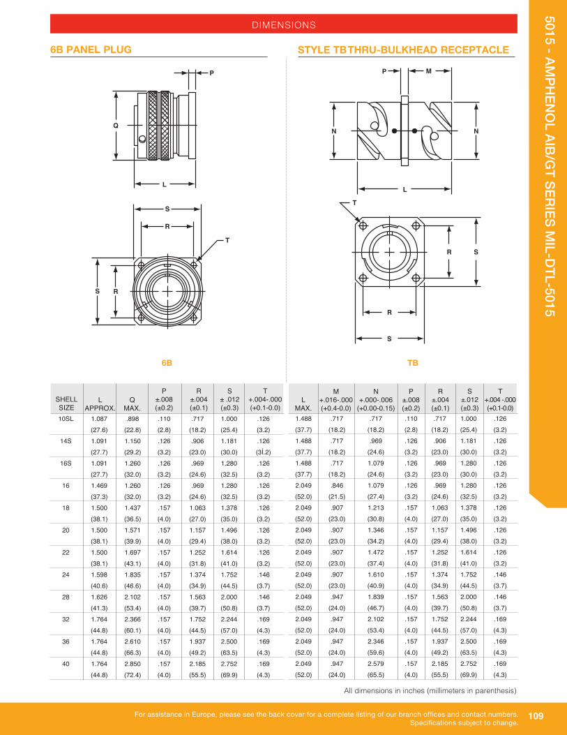
109
5015 - AMPH
ENO
L AIB/GT SERIES M
IL-DTL-5015
For assistance in Europe, please see the back cover for a complete listing of our branch offices and contact numbers.Specifications subject to change.
SHELL SIZE
P ±.008 (±0.2)
R ±.004 (±0.1)
S ± .012 (±0.3)
T +.004-.000 (+0.1-0.0)
L
APPROX. 10SL 1.087 .898 .110 .717 1.000 .126 (27.6) (22.8) (2.8) (18.2) (25.4) (3.2) 14S 1.091 1.150 .126 .906 1.181 .126 (27.7) (29.2) (3.2) (23.0) (30.0) (3Í.2) 16S 1.091 1.260 .126 .969 1.280 .126 (27.7) (32.0) (3.2) (24.6) (32.5) (3.2) 16 1.469 1.260 .126 .969 1.280 .126 (37.3) (32.0) (3.2) (24.6) (32.5) (3.2) 18 1.500 1.437 .157 1.063 1.378 .126 (38.1) (36.5) (4.0) (27.0) (35.0) (3.2) 20 1.500 1.571 .157 1.157 1.496 .126 (38.1) (39.9) (4.0) (29.4) (38.0) (3.2) 22 1.500 1.697 .157 1.252 1.614 .126 (38.1) (43.1) (4.0) (31.8) (41.0) (3.2) 24 1.598 1.835 .157 1.374 1.752 .146 (40.6) (46.6) (4.0) (34.9) (44.5) (3.7) 28 1.626 2.102 .157 1.563 2.000 .146 (41.3) (53.4) (4.0) (39.7) (50.8) (3.7) 32 1.764 2.366 .157 1.752 2.244 .169 (44.8) (60.1) (4.0) (44.5) (57.0) (4.3) 36 1.764 2.610 .157 1.937 2.500 .169 (44.8) (66.3) (4.0) (49.2) (63.5) (4.3) 40 1.764 2.850 .157 2.185 2.752 .169 (44.8) (72.4) (4.0) (55.5) (69.9) (4.3)
Q
MAX.
DIMENSIONS
6B PANEL PLUG
P
Q
L
N N
P M
L
S
R
S R
T
R
R S
S
T
P ±.008 (±0.2)
R ±.004 (±0.1)
S ±.012 (±0.3)
T +.004 -.000 (+0.1-0.0)
1.488 .717 .717 .110 .717 1.000 .126 (37.7) (18.2) (18.2) (2.8) (18.2) (25.4) (3.2) 1.488 .717 .969 .126 .906 1.181 .126 (37.7) (18.2) (24.6) (3.2) (23.0) (30.0) (3.2) 1.488 .717 1.079 .126 .969 1.280 .126 (37.7) (18.2) (24.6) (3.2) (23.0) (30.0) (3.2) 2.049 .846 1.079 .126 .969 1.280 .126 (52.0) (21.5) (27.4) (3.2) (24.6) (32.5) (3.2) 2.049 .907 1.213 .157 1.063 1.378 .126 (52.0) (23.0) (30.8) (4.0) (27.0) (35.0) (3.2) 2.049 .907 1.346 .157 1.157 1.496 .126 (52.0) (23.0) (34.2) (4.0) (29.4) (38.0) (3.2) 2.049 .907 1.472 .157 1.252 1.614 .126 (52.0) (23.0) (37.4) (4.0) (31.8) (41.0) (3.2) 2.049 .907 1.610 .157 1.374 1.752 .146 (52.0) (23.0) (40.9) (4.0) (34.9) (44.5) (3.7) 2.049 .947 1.839 .157 1.563 2.000 .146 (52.0) (24.0) (46.7) (4.0) (39.7) (50.8) (3.7) 2.049 .947 2.102 .157 1.752 2.244 .169 (52.0) (24.0) (53.4) (4.0) (44.5) (57.0) (4.3) 2.049 .947 2.346 .157 1.937 2.500 .169 (52.0) (24.0) (59.6) (4.0) (49.2) (63.5) (4.3) 2.049 .947 2.579 .157 2.185 2.752 .169 (52.0) (24.0) (65.5) (4.0) (55.5) (69.9) (4.3)
L
MAX.
M +.016-.000 (+0.4-0.0)
N +.000-.006
(+0.00-0.15)
STYLE TB THRU-BULKHEAD RECEPTACLE
TB6B
All dimensions in inches (millimeters in parenthesis)
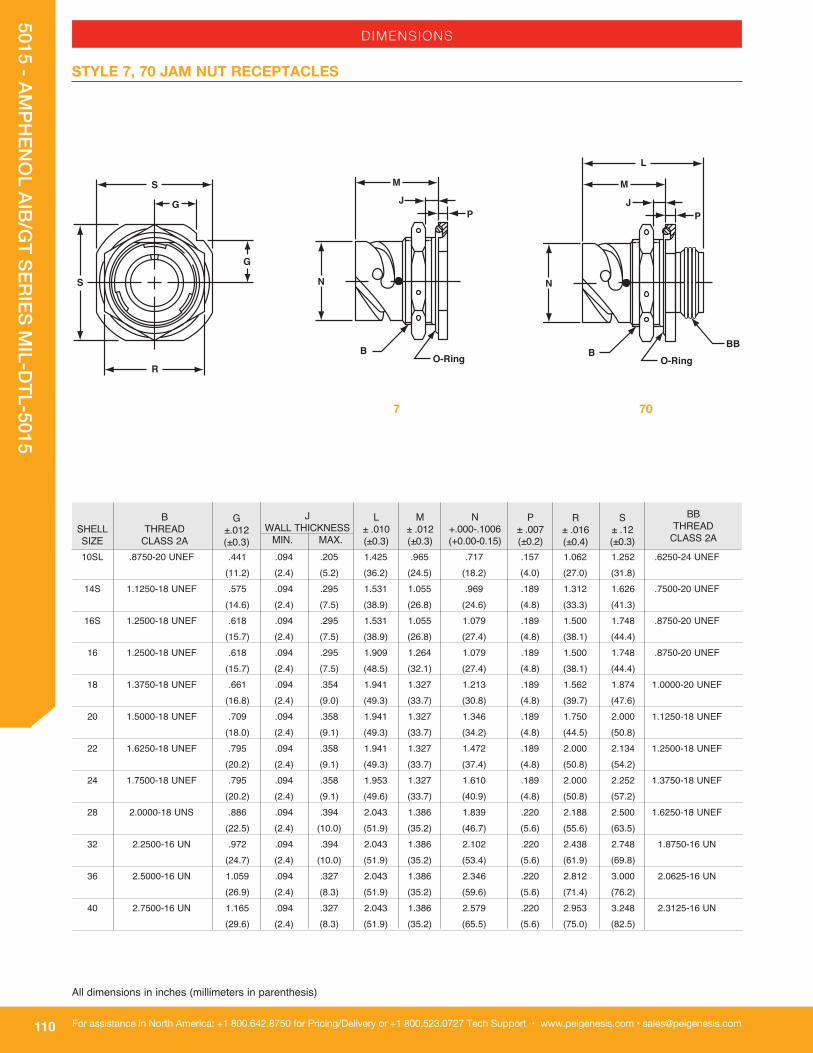
110
5015 - AMPH
ENO
L AIB/GT SERIES M
IL-DTL-5015
For assistance in North America: +1 800.642.8750 for Pricing/Delivery or +1 800.523.0727 Tech Support • www.peigenesis.com • [email protected]
All dimensions in inches (millimeters in parenthesis)
SHELL SIZE
10SL .8750-20 UNEF .441 .094 .205 1.425 .965 .717 .157 1.062 1.252 .6250-24 UNEF (11.2) (2.4) (5.2) (36.2) (24.5) (18.2) (4.0) (27.0) (31.8) 14S 1.1250-18 UNEF .575 .094 .295 1.531 1.055 .969 .189 1.312 1.626 .7500-20 UNEF (14.6) (2.4) (7.5) (38.9) (26.8) (24.6) (4.8) (33.3) (41.3) 16S 1.2500-18 UNEF .618 .094 .295 1.531 1.055 1.079 .189 1.500 1.748 .8750-20 UNEF (15.7) (2.4) (7.5) (38.9) (26.8) (27.4) (4.8) (38.1) (44.4) 16 1.2500-18 UNEF .618 .094 .295 1.909 1.264 1.079 .189 1.500 1.748 .8750-20 UNEF (15.7) (2.4) (7.5) (48.5) (32.1) (27.4) (4.8) (38.1) (44.4) 18 1.3750-18 UNEF .661 .094 .354 1.941 1.327 1.213 .189 1.562 1.874 1.0000-20 UNEF (16.8) (2.4) (9.0) (49.3) (33.7) (30.8) (4.8) (39.7) (47.6) 20 1.5000-18 UNEF .709 .094 .358 1.941 1.327 1.346 .189 1.750 2.000 1.1250-18 UNEF (18.0) (2.4) (9.1) (49.3) (33.7) (34.2) (4.8) (44.5) (50.8) 22 1.6250-18 UNEF .795 .094 .358 1.941 1.327 1.472 .189 2.000 2.134 1.2500-18 UNEF (20.2) (2.4) (9.1) (49.3) (33.7) (37.4) (4.8) (50.8) (54.2) 24 1.7500-18 UNEF .795 .094 .358 1.953 1.327 1.610 .189 2.000 2.252 1.3750-18 UNEF (20.2) (2.4) (9.1) (49.6) (33.7) (40.9) (4.8) (50.8) (57.2) 28 2.0000-18 UNS .886 .094 .394 2.043 1.386 1.839 .220 2.188 2.500 1.6250-18 UNEF (22.5) (2.4) (10.0) (51.9) (35.2) (46.7) (5.6) (55.6) (63.5) 32 2.2500-16 UN .972 .094 .394 2.043 1.386 2.102 .220 2.438 2.748 1.8750-16 UN (24.7) (2.4) (10.0) (51.9) (35.2) (53.4) (5.6) (61.9) (69.8) 36 2.5000-16 UN 1.059 .094 .327 2.043 1.386 2.346 .220 2.812 3.000 2.0625-16 UN (26.9) (2.4) (8.3) (51.9) (35.2) (59.6) (5.6) (71.4) (76.2) 40 2.7500-16 UN 1.165 .094 .327 2.043 1.386 2.579 .220 2.953 3.248 2.3125-16 UN (29.6) (2.4) (8.3) (51.9) (35.2) (65.5) (5.6) (75.0) (82.5)
L ± .010 (±0.3)
M ± .012 (±0.3)
N +.000-.1006 (+0.00-0.15)
JWALL THICKNESS
MIN. MAX.
G±.012(±0.3)
B THREAD
CLASS 2A
P ± .007 (±0.2)
R ± .016 (±0.4)
S ± .12 (±0.3)
DIMENSIONS
STYLE 7, 70 JAM NUT RECEPTACLES
G
S
S
G
R
BBTHREAD
CLASS 2A
7 70

111
5015 - AMPH
ENO
L AIB/GT SERIES M
IL-DTL-5015
For assistance in Europe, please see the back cover for a complete listing of our branch offices and contact numbers.Specifications subject to change.
DIMENSIONS
PANEL CUTOUTS
SHELL 7/70 PANEL CUTOUT SIZE F - FLAT D - DIAMETER 10SL 0.830 (21.1) 0.875 (22.2) 14S 1.080 (27.4) 1.125 (28.6) 16S/16 1.210 (30.7) 1.250 (31.7) 18 1.320 (33.5) 1.375 (34.9) 20 1.450 (36.8) 1.500 (38.1) 22 1.570 (39.9) 1.625 (41.3) 24 1.700 (43.2) 1.750 (44.5) 28 1.950 (49.5) 2.000 (50.8) 32 2.200 (55.9) 2.250 (57.2) 36 2.450 (62.2) 2.500 (63.5) 40 2.700 (68.6) 2.750 (69.9)
10SL .303 (7.70) 14S .303 (7.70) 16S .303 (7.70) 16 .242 (6.15) 18 .303 (7.70) 20 .303 (7.70) 22 .303 (7.70) 24 .303 (7.70) 28 .343 (8.70) 32 .309 (7.85) 36 .309 (7.85) 40 .309 (7.85)
PANEL THICKNESS
Dim. J-flange in front of panelDim. K-flange at rear of panelSee sealing screws on apage 439.
SHELL REAR SIZE MOUNT
Rear Mount
D
All dimensions in inches (millimeters in parenthesis)
SHELL SIZE STYLE 0, 2, 20, 30, TB FLANGEG (TP) MOUNTING
HOLE DIAMETER H
J FRONT K REAR
10SL 0.717 (18.2) 0.126 (3.2) 0.688 (17.5) 0.750 (19.1)14S 0.906 (23.0) 0.126 (3.2) 0.813 (20.7) 1.000 (25.4)16S 0.969 (24.6) 0.126 (3.2) 0.938 (23.8) 1.125 (28.6)16 0.969 (24.6) 0.126 (3.2) 0.938 (23.8) 1.125 (28.6)18 1.063 (27.0) 0.126 (3.2) 1.063 (27.0) 1.250 (26.7)20 1.157 (29.4) 0.126 (3.2) 1.188 (30.2) 1.375 (35.0)22 1.252 (31.8) 0.126 (3.2) 1.313 (33.4) 1.500 (38.1)24 1.374 (34.9) 0.146 (3.7) 1.438 (36.5) 1.625 (41.3)28 1.563 (39.7) 0.146 (3.7) 1.688 (42.9) 1.875 (47.6)32 1.752 (44.5) 0.169 (4.3) 1.938 (49.2) 2.125 (54.0)36 1.937 (49.2) 0.169 (4.3) 2.125 (54.0) 2.375 (60.3)40 2.185 (55.5) 0.169 (4.3) 2.375 (60.3) 2.625 (66.7)
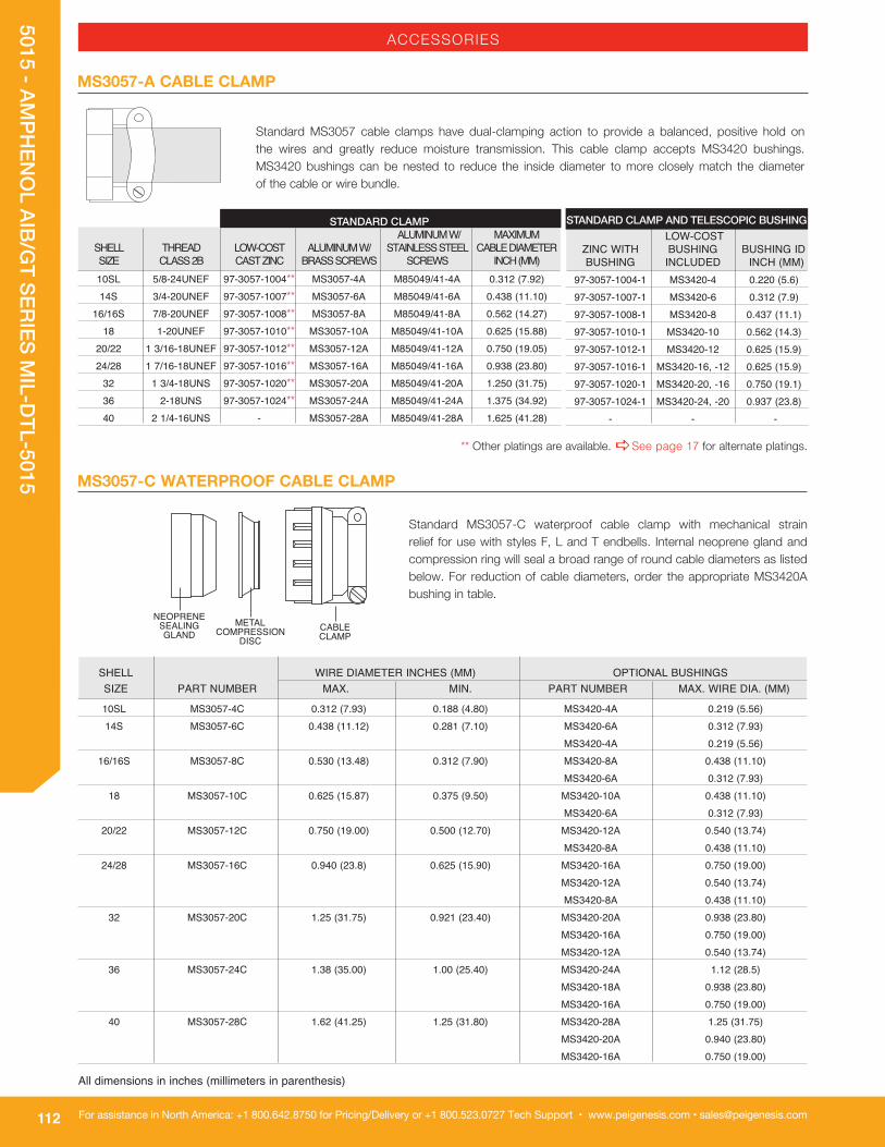
112
5015 - AMPH
ENO
L AIB/GT SERIES M
IL-DTL-5015
For assistance in North America: +1 800.642.8750 for Pricing/Delivery or +1 800.523.0727 Tech Support • www.peigenesis.com • [email protected]
ACCESSORIES
MS3057-A CABLE CLAMP
MS3057-C WATERPROOF CABLE CLAMP
Standard MS3057-C waterproof cable clamp with mechanical strain relief for use with styles F, L and T endbells. Internal neoprene gland and compression ring will seal a broad range of round cable diameters as listed below. For reduction of cable diameters, order the appropriate MS3420A bushing in table.
SHELL WIRE DIAMETER INCHES (MM) OPTIONAL BUSHINGS SIZE PART NUMBER MAX. MIN. PART NUMBER MAX. WIRE DIA. (MM)
10SL MS3057-4C 0.312 (7.93) 0.188 (4.80) MS3420-4A 0.219 (5.56) 14S MS3057-6C 0.438 (11.12) 0.281 (7.10) MS3420-6A 0.312 (7.93) MS3420-4A 0.219 (5.56) 16/16S MS3057-8C 0.530 (13.48) 0.312 (7.90) MS3420-8A 0.438 (11.10) MS3420-6A 0.312 (7.93) 18 MS3057-10C 0.625 (15.87) 0.375 (9.50) MS3420-10A 0.438 (11.10) MS3420-6A 0.312 (7.93) 20/22 MS3057-12C 0.750 (19.00) 0.500 (12.70) MS3420-12A 0.540 (13.74) MS3420-8A 0.438 (11.10) 24/28 MS3057-16C 0.940 (23.8) 0.625 (15.90) MS3420-16A 0.750 (19.00) MS3420-12A 0.540 (13.74) MS3420-8A 0.438 (11.10) 32 MS3057-20C 1.25 (31.75) 0.921 (23.40) MS3420-20A 0.938 (23.80) MS3420-16A 0.750 (19.00) MS3420-12A 0.540 (13.74) 36 MS3057-24C 1.38 (35.00) 1.00 (25.40) MS3420-24A 1.12 (28.5) MS3420-18A 0.938 (23.80) MS3420-16A 0.750 (19.00) 40 MS3057-28C 1.62 (41.25) 1.25 (31.80) MS3420-28A 1.25 (31.75) MS3420-20A 0.940 (23.80) MS3420-16A 0.750 (19.00)
Standard MS3057 cable clamps have dual-clamping action to provide a balanced, positive hold on the wires and greatly reduce moisture transmission. This cable clamp accepts MS3420 bushings. MS3420 bushings can be nested to reduce the inside diameter to more closely match the diameter of the cable or wire bundle.
STANDARD CLAMP ALUMINUM W/ MAXIMUM SHELL THREAD LOW-COST ALUMINUM W/ STAINLESS STEEL CABLE DIAMETER SIZE CLASS 2B CAST ZINC BRASS SCREWS SCREWS INCH (MM) 10SL 5/8-24UNEF 97-3057-1004** MS3057-4A M85049/41-4A 0.312 (7.92) 14S 3/4-20UNEF 97-3057-1007** MS3057-6A M85049/41-6A 0.438 (11.10) 16/16S 7/8-20UNEF 97-3057-1008** MS3057-8A M85049/41-8A 0.562 (14.27) 18 1-20UNEF 97-3057-1010** MS3057-10A M85049/41-10A 0.625 (15.88) 20/22 1 3/16-18UNEF 97-3057-1012** MS3057-12A M85049/41-12A 0.750 (19.05) 24/28 1 7/16-18UNEF 97-3057-1016** MS3057-16A M85049/41-16A 0.938 (23.80) 32 1 3/4-18UNS 97-3057-1020** MS3057-20A M85049/41-20A 1.250 (31.75) 36 2-18UNS 97-3057-1024** MS3057-24A M85049/41-24A 1.375 (34.92) 40 2 1/4-16UNS - MS3057-28A M85049/41-28A 1.625 (41.28)
STANDARD CLAMP AND TELESCOPIC BUSHING LOW-COST ZINC WITH BUSHING BUSHING ID BUSHING INCLUDED INCH (MM) 97-3057-1004-1 MS3420-4 0.220 (5.6) 97-3057-1007-1 MS3420-6 0.312 (7.9) 97-3057-1008-1 MS3420-8 0.437 (11.1) 97-3057-1010-1 MS3420-10 0.562 (14.3) 97-3057-1012-1 MS3420-12 0.625 (15.9) 97-3057-1016-1 MS3420-16, -12 0.625 (15.9) 97-3057-1020-1 MS3420-20, -16 0.750 (19.1) 97-3057-1024-1 MS3420-24, -20 0.937 (23.8) - - -
All dimensions in inches (millimeters in parenthesis)
** Other platings are available. aSee page 17 for alternate platings.

113
5015 - AMPH
ENO
L AIB/GT SERIES M
IL-DTL-5015
For assistance in Europe, please see the back cover for a complete listing of our branch offices and contact numbers.Specifications subject to change.
SHELL SIZE INCHES (mm) (mm)INCHESCABLE CLAMPPART NUMBER
MAX. CABLE OD MIN. CABLE OD THREADCLASS 2B
10SL 9767-12-4 0.219 (5.55) 0.020 (0.51) 5/8-24 UNEF 14S 9767-14-4 0.219 (5.55) 0.020 (0.51) 3/4-20 UNEF 14S 9767-14-6 0.344 (8.73) 0.176 (4.47) 3/4-20 UNEF 16S/16 9767-16-4 0.219 (5.55) 0.020 (0.51) 7/8-20 UNEF 16S/16 9767-16-6 0.344 (8.73) 0.176 (4.47) 7/8-20 UNEF 16S/16 9767-16-8 0.438 (11.12) 0.177 (4.50) 7/8-20 UNEF 18 9767-18-6 0.344 (8.73) 0.176 (4.47) 1-20 UNEF 18 9767-18-8 0.438 (11.12) 0.177 (4.50) 1-20 UNEF 18 9767-18-10 0.563 (14.29) 0.292 (7.42) 1-20 UNEF 20/22 9767-22-8 0.438 (11.12) 0.177 (4.50) 1-3/16-18 UNEF 20/22 9767-22-10 0.563 (14.29) 0.292 (7.42) 1-3/16-18 UNEF 20/22 9767-22-12 0.688 (17.46) 0.370 (9.40) 1-3/16-18 UNEF 24/28 9767-28-10 0.563 (14.29) 0.292 (7.42) 1-7/16-18 UNEF 24/28 9767-28-12 0.688 (17.46) 0.370 (9.40) 1-7/16-18 UNEF 24/28 9767-28-16 0.844 (21.43) 0.536 (13.61) 1-7/16-18 UNEF 32 9767-32-20 1.031 (26.19) 0.590 (14.99) 1-3/4-18 UNS 36 9767-36-16 0.844 (21.43) 0.536 (13.61) 2-18 UNS
ACCESSORIES
9767 CABLE CLAMPS
SIZEFITS IN
CABLE CLAMPINSIDE
DIAMETERINSIDE
DIAMETER1ST BUSHING
PART NUMBER2ND NESTED
BUSHING
10SL MS3420-4 .220 (5.59) NONE - MS3057-4A 14S MS3420-6 .312 (7.92) NONE - MS3057-6A 16S MS3420-8 .437 (11.10) NONE - MS3057-8A 16 MS3420-8 .437 (11.10) NONE - MS3057-8A 18 MS3420-10 .562 (14.30) NONE - MS3057-10A 20 MS3420-12 .625 (15.90) NONE - MS3057-12A 22 MS3420-12 .625 (15.90) NONE - MS3057-12A 24 MS3420-16 .750 (19.05) MS3420-12 .625 (15.90) MS3057-16A 28 MS3420-16 .750 (19.05) MS3420-12 .625 (15.90) MS3057-16A 32 MS3420-20 .937 (23.80) MS3420-16 .750 (19.05) MS3057-20A 36 MS3420-24 1.250 (31.75) MS3420-20 .937 (23.80) MS3057-24A 40 MS3420-28 1.375 (34.92) MS3420-24 1.250 (31.75) SE96-28A4
For use with style-A cable clamps and AIT/MS style-E/F endbells to resist dust, dirt and oil. Bushings can be nested, one inside the other, to reduce the inside diameter and form a better seal against the cable jacket. Each bushing will accept the next smallest bushing.
MS3420 TELESCOPING BUSHINGS
9767 waterproof cable clamp with mechanical strain relief. An internal neoprene gland seal bushing and compression washer will seal a broad range of round cable diameters, as listed below.
For use with MS3057-C cable clamps (style-C) to reduce the wire sealing diameter. Bushings can be nested, one inside the other, to progressively reduce the inside diameter of the cable clamp. The column labeled “re duction bushings” shows the acceptable nesting options for each clamp.
MS3420-A REDUCTION BUSHINGS
All dimensions in inches (millimeters in parenthesis)

114
5015 - AMPH
ENO
L AIB/GT SERIES M
IL-DTL-5015
For assistance in North America: +1 800.642.8750 for Pricing/Delivery or +1 800.523.0727 Tech Support • www.peigenesis.com • [email protected]
Metal dust caps are used to protect the contacts when the connectors are left unmated. Dust caps come with metal chain lanyards. Dummy Receptacles are for front or rear-panel mounting. AIB/GT Series connectors have bayonet ramps. The center of the connector is closed. Dummy receptacles mount on the same centers and have the same outside dimensions as a STYLE 2 receptacle. A version with a clearance hole through the middle of the connector is also available. Contact us for ordering information.
D9
ACCESSORIES
Synthetic rubber gaskets are used to ensure a moisture-tight seal between a receptacle and the panel. Gaskets are available for front or rear-panel mounting of styles 0, 2, 20, 30 and TB connectors. Gasket thickness is approximately .031 inches (1 mm), for nonconductive and low-temperature types.
Conductive shielding gaskets contain an embedded metal screen for EMI/RFI shielding in addition to moisture sealing. Gaskets are available for front or rear-panel mounting of styles 30 and TB connectors. Gasket thickness is .020 inches (.5 mm).
GASKETS
NON-CONDUCTIVE LOW-TEMPERATURE CONDUCTIVESHELL SIZE NON-CONDUCTIVE 10SL 10-040450-010 10-040450-10S 10-036675-010 10-580649-011 14S 10-040450-014 10-040450-14S 10-036675-014 10-580649-014 16S 10-040450-016 10-040450-16S 10-036675-016 10-580649-016 16 10-040450-016 10-040450-16S 10-036675-016 10-580649-016 18 10-040450-018 10-040450-18S 10-036675-018 10-580649-018 20 10-040450-020 10-040450-20S 10-036675-020 10-580649-020 22 10-040450-022 10-040450-22S 10-036675-022 10-580649-022 24 10-040450-024 10-040450-24S 10-036675-024 10-580649-024 28 10-040450-028 10-040450-28S 10-036675-028 10-580649-028 32 10-040450-032 10-040450-32S 10-036675-032 10-580649-032 36 10-040450-036 10-040450-36S 10-036675-036 10-580649-036 40 10-040450-040 10-040450-40S 10-036675-040 10-580649-040
METAL DUST CAPS WITH SASH CHAIN
10SL 10-580903-11* 10-580902-11* 10-580595-11* 10-564843-101 14S 10-580903-14* 10-580902-14* 10-580595-14* 10-564843-141 16S 10-580903-16* 10-580902-16* 10-580595-16* 10-564843-161 16 10-580903-17* 10-580902-17* 10-580595-17* 10-564843-161 18 10-580903-18* 10-580902-18* 10-580595-18* 10-564843-181 20 10-580903-20* 10-580902-20* 10-580595-20* 10-564843-201 22 10-580903-22* 10-580902-22* 10-580595-22* 10-564843-221 24 10-580903-24* 10-580902-24* 10-580595-24* 10-564843-241 28 10-580903-28* 10-580902-28* 10-580595-28* 10-564843-281 32 10-580903-32* 10-580902-32* 10-580595-32* 10-564843-321 36 10-580903-36* 10-580902-36* 10-580595-36* 10-564843-161 40 10-580903-40* 10-580902-40* 10-580595-40* 10-564843-401
SHELLSIZE
PLUG CAP RECEPTACLE PLUG SEAL RINGDUMMY RECEPTACLESDUST CAPS
FRONT MOUNT REAR MOUNT
1,8 ±0,2
3 ±0,2
*Select code for plating:Z = Black anodize3 = Olive drab cadmium plate
9 = Olive drab cadmium nickel baseG = Electroless nickel
U = Green zincY = Black alloy
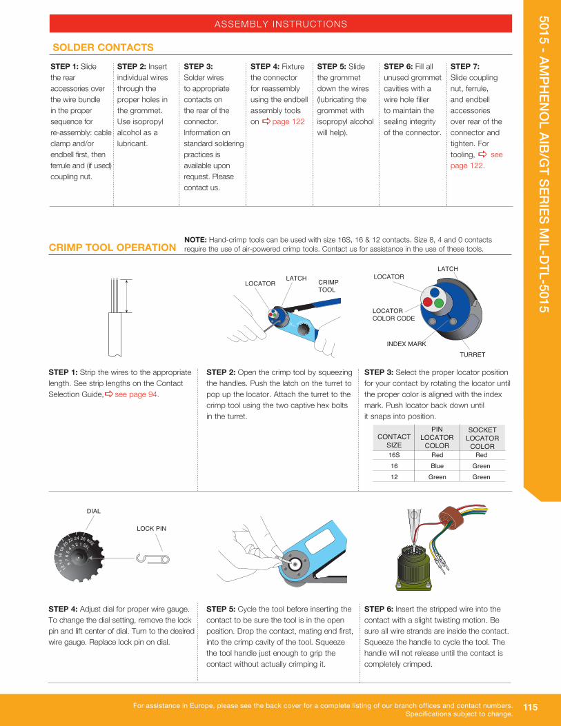
115
5015 - AMPH
ENO
L AIB/GT SERIES M
IL-DTL-5015
For assistance in Europe, please see the back cover for a complete listing of our branch offices and contact numbers.Specifications subject to change.
ASSEMBLY INSTRUCTIONS
LOCK PIN
DIAL
STEP 1: Slide the rear accessories over the wire bundle in the proper sequence for re-assembly: cable clamp and/or endbell first, then ferrule and (if used) coupling nut.
STEP 2: Insert individual wires through the proper holes in the grommet. Use isopropyl alcohol as a lubricant.
STEP 3: Solder wires to appropriate contacts on the rear of the connector. Information on standard soldering practices is available upon request. Please contact us.
STEP 4: Fixture the connector for reassembly using the endbell assembly tools on apage 122
STEP 5: Slide the grommet down the wires (lubricating the grommet with isopropyl alcohol will help).
STEP 6: Fill all unused grommet cavities with a wire hole filler to maintain the sealing integrity of the connector.
STEP 7: Slide coupling nut, ferrule, and endbell accessories over rear of the connector and tighten. For tooling, a see page 122.
SOLDER CONTACTS
LOCATOR
INDEX MARK
LOCATORCOLOR CODE
LATCH
TURRET
PIN LOCATOR
COLORCONTACT
SIZE 16S Red Red 16 Blue Green 12 Green Green
SOCKET LOCATOR
COLOR
CRIMP TOOL OPERATION NOTE: Hand-crimp tools can be used with size 16S, 16 & 12 contacts. Size 8, 4 and 0 contacts require the use of air-powered crimp tools. Contact us for assistance in the use of these tools.
STEP 1: Strip the wires to the appropriate length. See strip lengths on the Contact Selection Guide,asee page 94.
STEP 2: Open the crimp tool by squeezing the handles. Push the latch on the turret to pop up the locator. Attach the turret to the crimp tool using the two captive hex bolts in the turret.
STEP 3: Select the proper locator position for your contact by rotating the locator until the proper color is aligned with the index mark. Push locator back down until it snaps into position.
LATCH CRIMPTOOL
LOCATOR
STEP 4: Adjust dial for proper wire gauge. To change the dial setting, remove the lock pin and lift center of dial. Turn to the desired wire gauge. Replace lock pin on dial.
STEP 5: Cycle the tool before inserting the contact to be sure the tool is in the open position. Drop the contact, mating end first, into the crimp cavity of the tool. Squeeze the tool handle just enough to grip the contact without actually crimping it.
STEP 6: Insert the stripped wire into the contact with a slight twisting motion. Be sure all wire strands are inside the contact. Squeeze the handle to cycle the tool. The handle will not release until the contact is completely crimped.
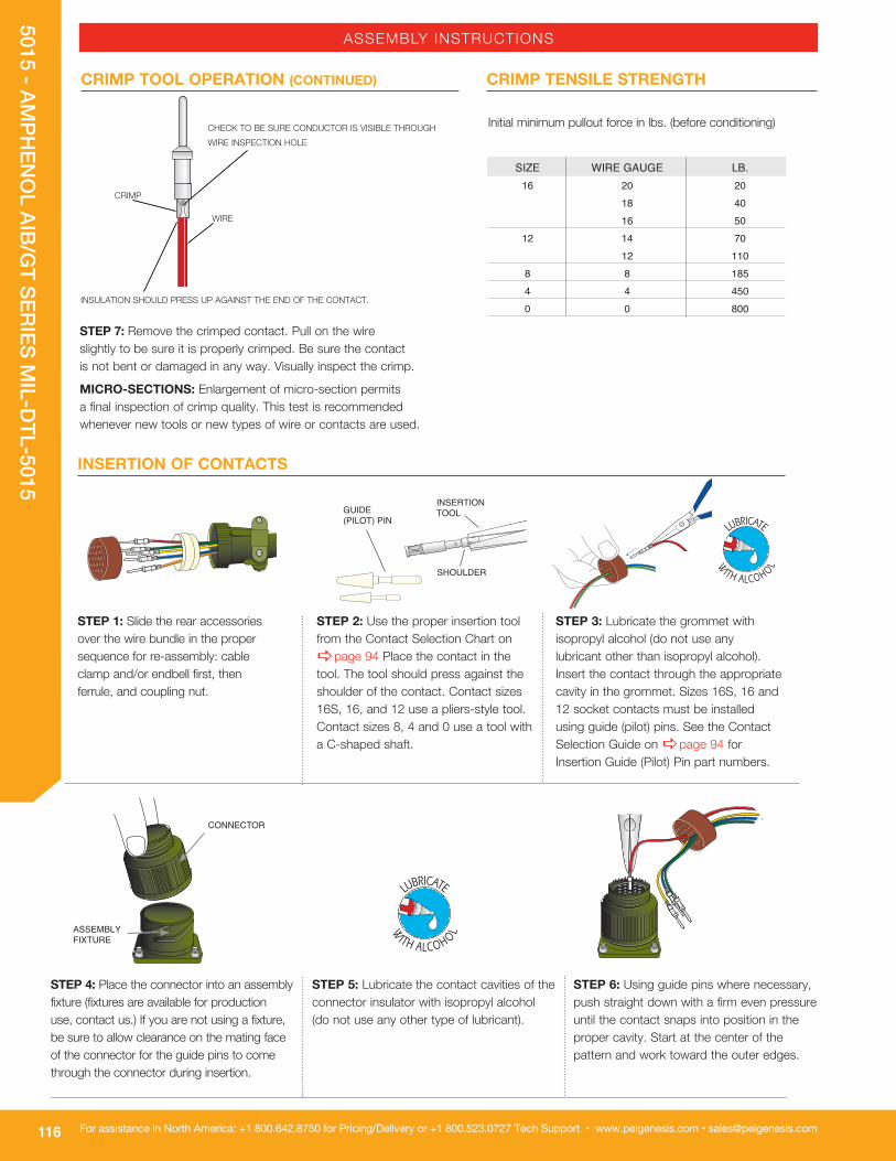
116
5015 - AMPH
ENO
L AIB/GT SERIES M
IL-DTL-5015
For assistance in North America: +1 800.642.8750 for Pricing/Delivery or +1 800.523.0727 Tech Support • www.peigenesis.com • [email protected]
WIRE
CRIMP
CHECK TO BE SURE CONDUCTOR IS VISIBLE THROUGH WIRE INSPECTION HOLE
STEP 7: Remove the crimped contact. Pull on the wire slightly to be sure it is properly crimped. Be sure the contact is not bent or damaged in any way. Visually inspect the crimp.
MICRO-SECTIONS: Enlargement of micro-section permits a final inspection of crimp quality. This test is recommended whenever new tools or new types of wire or contacts are used.
Initial minimum pullout force in lbs. (before conditioning) SIZE WIRE GAUGE LB. 16 20 20 18 40 16 50 12 14 70 12 110 8 8 185 4 4 450 0 0 800
CRIMP TOOL OPERATION (CONTINUED) CRIMP TENSILE STRENGTH
INSULATION SHOULD PRESS UP AGAINST THE END OF THE CONTACT.
GUIDE (PILOT) PIN
SHOULDER
INSERTION TOOL
INSERTION OF CONTACTS
ASSEMBLYFIXTURE
STEP 1: Slide the rear accessories over the wire bundle in the proper sequence for re-assembly: cable clamp and/or endbell first, then ferrule, and coupling nut.
STEP 2: Use the proper insertion tool from the Contact Selection Chart on apage 94 Place the contact in the tool. The tool should press against the shoulder of the contact. Contact sizes 16S, 16, and 12 use a pliers-style tool. Contact sizes 8, 4 and 0 use a tool with a C-shaped shaft.
STEP 3: Lubricate the grommet with isopropyl alcohol (do not use any lubricant other than isopropyl alcohol). Insert the contact through the appropriate cavity in the grommet. Sizes 16S, 16 and 12 socket contacts must be installed using guide (pilot) pins. See the Contact Selection Guide on apage 94 for Insertion Guide (Pilot) Pin part numbers.
STEP 4: Place the connector into an assembly fixture (fixtures are available for production use, contact us.) If you are not using a fixture, be sure to allow clearance on the mating face of the connector for the guide pins to come through the connector during insertion.
STEP 5: Lubricate the contact cavities of the connector insulator with isopropyl alcohol (do not use any other type of lubricant).
STEP 6: Using guide pins where necessary, push straight down with a firm even pressure until the contact snaps into position in the proper cavity. Start at the center of the pattern and work toward the outer edges.
CONNECTOR
ASSEMBLY INSTRUCTIONS

117
5015 - AMPH
ENO
L AIB/GT SERIES M
IL-DTL-5015
For assistance in Europe, please see the back cover for a complete listing of our branch offices and contact numbers.Specifications subject to change.
PIN CONTACT SOCKET CONTACT
CROSS SECTION OF CONNECTOR
CROSS SECTION OF CONNECTOR
SOFT JAW PLIERS
EXTRACTION OF CONTACTS
UNCRIMPED CONTACTS
PIN EXTRACTION END
HANDLE
LOCK RING
SOCKET EXTRACTION END
INSERTION OF CONTACTS (CONTINUED)
STEP 7: Fill any unused cavities with contacts.
STEP 8: Check the mating face of the connector to ensure that all the same size contacts are on the same plane (fully inserted). If not, the contact is not fully inserted. Remove the contact using the proper extraction tool and procedure and reinsert. Do not attempt to reinsert the insertion tool to correct the problem.
STEP 9: A wire hole filler must be inserted into the grommet behind the unused contacts to maintain the sealing integrity of the connector. See the Contact Selection Chart on apage 94 for wire hole fillers.
STEP 10: Place the connector back in the fixture for re-assembly. Slide the connector accessories back down the cable over the rear of the connector and tighten. Use the appropriate endbell tools as shown on apage 122.
STEP 1: Remove the endbell accessories and slide them back over the wires. Use the appropriate endbell tools as shown on apage 122.
STEP 2: Use the proper extraction tool from the Contact Selection Chart on apage 94. The extraction tool can be used for both pin and socket contacts by removing the shaft from the handle and reversing it for pin or socket extraction.
STEP 3: On the mating face of the connector, insert the tool over the pin contact or into the socket contact until the tool bottoms. Apply a slow continuous pressure to push the contact out the rear of the connector. When the shoulder of the tool “thunks” against the insulator, the contact is extracted.
STEP 4: Carefully remove the extraction tool from the connector to avoid damage to the insulator.
ASSEMBLY INSTRUCTIONS

118
5015 - AMPH
ENO
L AIB/GT SERIES M
IL-DTL-5015
For assistance in North America: +1 800.642.8750 for Pricing/Delivery or +1 800.523.0727 Tech Support • www.peigenesis.com • [email protected]
AMPHENOL HOW-TO-ORDER GUIDE
AIB/GT SERIES CONNECTORS
MATEABILITY WITH IDENTICAL CONTACT ARRANGEMENTS
CONNECTOR STYLE MATEABLE WITH STYLE
GT00 GT06/062/064/065/08 GT01 GT06/062/064/065/08 GT02 GT06/062/064/065/08 GT020 GT06/062/064/065/08 GT030 GT06/062/064/065/08 GT06/062/064/065 GT00/01/02/020/03/030/05/070/TB GT07/070 GT06/062/064/065/08 GT08 GT00/01/02/020/03/030/05/070/TB GTTB GT06/062/064/065/08
SERIES GT Circular connectors with bayonet coupling
SHELL SIZE & LAYOUT See apages 72-82.
GT C 00 A 36-5 P W- (002)
CONTACT STYLE/INSERT C = Crimp S = Solder CY = Crimp with Viton®*
SY = Solder with Viton®*
CL = Crimp with low-smoke/flame- retardant inserts SL = Solder with low-smoke/flame- retardant inserts
SHELL STYLE 00 Wall-mount receptacle 01 Inline receptacle 02 Box-mount receptacle 020 Box-mount receptacle with accessory threads 030 Square flange receptacle - rear panel mount (most popular) 05 Dummy receptacle 06 Straight plug (most popular) 062 Straight plug with deep-serrated coupling nut 064 Panel-mounted plug with heavy-duty coupling nut 065 Straight plug with long heavy-duty coupling nut 07 Jam nut receptacle - rear panel mount 070 Jam nut receptacle with accessory threads 08 90˚ angle plug TB Thru-bulkhead
CONNECTOR SHELL VARIATIONS Omit for standard olive drab with silver plated contacts G96 Black anodized 014 Olive drab cadmium plate, nickel base A24 Gold/nickel-plated contacts 023 Electroless nickel (RoHS with crimp only) 025 Black alloy (RoHS with crimp only) 027 Conductive black alloy (RoHS with crimp only) 024 Green zinc B30 Gold RDS Radsok power contacts 8, 4 & 0 socket contact only 116 Less pre-tinned solder cups 472 116 & 025 mod codes (RoHS) 548 116 & 023 mod codes (RoHS) 553 116 & 027 mod codes (RoHS)ALTERNATE INSERT ROTATIONW, X, Y, and Z designate that the insert is rotated in its shell from a normal position. No letter required for normal (no rotation) position. See apages 83-93.
CONTACT STYLE P pin contacts S socket contacts
CONNECTOR CLASSA General-duty, threaded backshell, no cable clamp,
no grommetAF General-duty, threaded backshell, cable clamp, no grommetF General-duty, threaded backshell, cable clamp, with grommetCF General-duty, threaded endbell, gland-seal cable
clamp, no grommetCFZ General-duty, threaded endbell, gland-seal cable
clamp, with grommetG One-piece, heat shrink endbell adaptor, with grommet
(use with heat shrink boot – see Accessories).apages 440-441
G2 Two-piece, heat shrink endbell adaptor, with grommet (use with heat shrink boot – see Accessories). apages 440-441LC Long-threaded backshell, gland-seal cable clamp,
with grommet, and basket-weave cord grip (please call with cable O.D.)
LCF Long-threaded endbell, gland-seal cable clamp, no grommetLCFZ Long-threaded endbell, gland-seal cable clamp, with grommetR General-duty, threaded backshell, no cable clamp,
with grommetRV General-duty, short backshell, with grommet
(may be used with heat shrink boot – see Accessories). apages 440-441
CFGG General-duty, threaded endbell, gland-seal cable clamp, no grommet, rubber-covered coupling nut (shell styles 06 and 08 only)
PP Panel plug, only for shell styles 06 and 064LT Long back shell for metal core conduit, with grommet
(please call with conduit O.D.)PFC For plastic, flexible conduit (please call with conduit
O.D.) asee pages 445SL Long backshell for use with PG gland-seal style cord
grip (please call with cable O.D.)
*Viton® is a registered trademark of DuPont DOW Elastomers

119
5015 - AMPH
ENO
L AIB/GT SERIES M
IL-DTL-5015
For assistance in Europe, please see the back cover for a complete listing of our branch offices and contact numbers.Specifications subject to change.
AMPHENOL HOW-TO-ORDER GUIDE
AIBC/ACA-B SERIES CONNECTORS
SERIES ACA Circular Connector Family
SHELL STYLES 3100 - Wall-mount receptacle with
rear accessory threads for front mounting through holes in flange
3101 - Cable-connecting receptacle with rear accessory threads
3102 - Front-mount box receptacle no rear accessory threads through holes in flange
3103 - Rear-mount box receptacle with rear accessory threads through holes in flange
3106 - Plug straight 3107A - Jam nut receptacle rear mount,
no rear accessory threads 3108 - Plug with 90 degree endbell
CONNECTOR CLASS E Environmental with resilient insulator
and endbell with clamp and bushing F Environmental with resilient insulator
and endbell with rear accessory threads
G Two-piece backshell for heat shrink boots
R Environmental with resilient insulator and shortened lightweight endbell without cable clamp
SHELL SIZE 10SL, 14S, 16S, 16, 18, 20, 22, 24, 28, 32,
and 36
CONNECTOR MODIFICATION 01 - Metric crimp contacts 116 - Less solder filled contacts F80 - AWG crimp contacts A176 - Gold-plated contacts A23 - Electroless nickel plating shells A232 - Black zinc cobalt-plated shells F42 - Less grommet, endbell & sleeve (ferrule) F0 - Less contacts (ordered separately) RFI - Grounding spring on barrel
(3106 & 3108) T00 - Metric threaded holes in flange
(3100, 3102, 3103 only) Contact us for other modifications
REVERSE BAYONET COUPLING
ALTERNATE ROTATION W, X, Y, and Z No suffix required for normal position aSee pages 83-93 for valid alternate insert position (rotation)
CONTACT TYPE P - Pin S - Socket
CONNECTOR ARRANGEMENT aSee pages 72-82 for layouts by number of contacts
ACA 3106 E 18 1 S X B - F80
To more easily illustrate ordering procedure, part number ACA3106E181SXB-F80 is shown as follows:
Use the AIB/GT Series part numbering system on apages 70-71 whenever possible.
MATEABILITY WITH IDENTICAL CONTACT ARRANGEMENTS
CONNECTOR STYLE MATEABLE WITH STYLE
ACA 3100 ACA3106/ ACA3108 ACA 3101 ACA3106/ ACA3108 ACA 3102 ACA3106/ ACA3108 ACA 3103 ACA3106/ ACA3108 ACA 3105 ACA3106/ ACA3108 ACA 3106 ACA3101/ ACA3102/ ACA3103 ACA 3108 ACA3101/ ACA3102/ ACA3103

120
5015 - AMPH
ENO
L AIB/GT SERIES M
IL-DTL-5015
For assistance in North America: +1 800.642.8750 for Pricing/Delivery or +1 800.523.0727 Tech Support • www.peigenesis.com • [email protected]
AMPHENOL HOW TO ORDER GUIDE
VG95234 NATO SPECIFICATIONS
SHELL STYLE See chart below
VG95234- A 20-29 P 1 N
SHELL SIZE - LAYOUT a See pages 72-82.
PLUGS D Straight plug with cable clamp E Right angle plug with cable clamp E1 Right angle plug for conduit termination G Straight plug with heat shrink endbell H Straight plug for conduit termination K Right angle plug for conduit termination with grounding fingers L Straight plug for conduit termination with grounding fingers M Straight plug with shielded heat shrink endbell and grounding fingers R1 Straight plug with shielded heat shrink endbell and grounding fingers T Straight plug with heat shrink endbell and grounding fingers
RECEPTACLES A Front panel mount box receptacle B1 Rear panel mount box receptacle, metric mounting holes B2 Rear panel mount box receptacle, through mounting holes F In-line receptacle with cable clamp J1 Rear panel mount wall receptacle with cable clamp, metric mounting holes J2 Rear panel mount wall receptacle with cable clamp, through mounting holes N1 Rear panel mount wall receptacle with shielded heat shrink endbell, metric mounting holes N2 Rear panel mount wall receptacle with shielded heat shrink endbell, through mounting holes S1 Rear panel mount wall receptacle with heat shrink endbell, metric mounting holes S2 Rear panel mount wall receptacle with heat shrink endbell, through mounting holes U1 Rear panel mount wall receptacle with heat shrink endbell, metric mounting holes U2 Rear panel mount wall receptacle with heat shrink endbell, through mounting holes V In-Line receptacle with conduit termination
CONTACT STYLE P = Pin contacts S = Socket contacts
TERMINATION 1 = AWG crimp Blank = metric crimp
POLARIZATION a See pages 83-93.
SHELL STYLE
Mates with
VG SPEC PREFIX
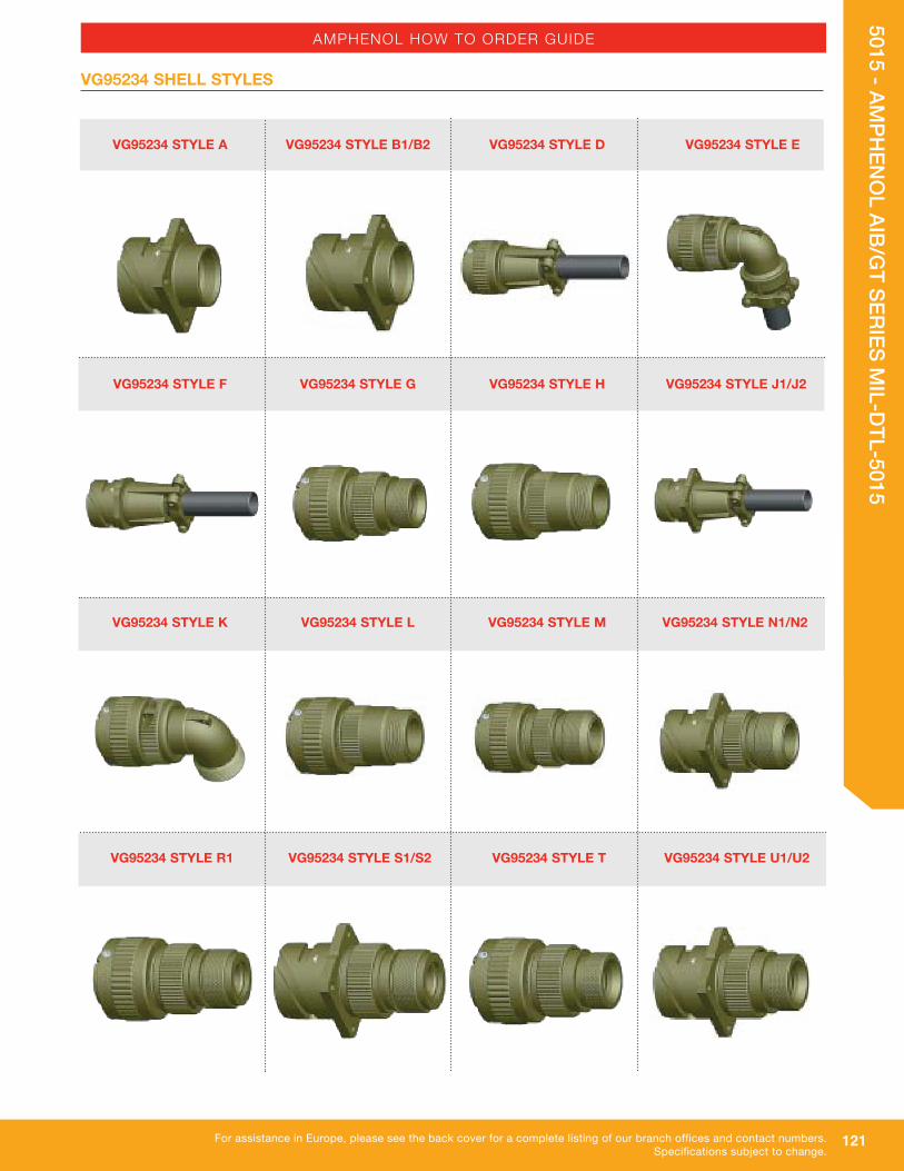
121
5015 - AMPH
ENO
L AIB/GT SERIES M
IL-DTL-5015
For assistance in Europe, please see the back cover for a complete listing of our branch offices and contact numbers.Specifications subject to change.
AMPHENOL HOW TO ORDER GUIDE
VG95234 SHELL STYLES
VG95234 STYLE F VG95234 STYLE G VG95234 STYLE H VG95234 STYLE J1/J2
VG95234 STYLE R1 VG95234 STYLE S1/S2 VG95234 STYLE T VG95234 STYLE U1/U2
VG95234 STYLE A VG95234 STYLE B1/B2 VG95234 STYLE D VG95234 STYLE E
VG95234 STYLE K VG95234 STYLE L VG95234 STYLE M VG95234 STYLE N1/N2

122
5015 - AMPH
ENO
L AIB/GT SERIES M
IL-DTL-5015
For assistance in North America: +1 800.642.8750 for Pricing/Delivery or +1 800.523.0727 Tech Support • www.peigenesis.com • [email protected]
CONNECTOR TOOLS
TG70 STRAP WRENCH
The strap wrench is used to connect or disconnect coupling nuts in a confined space, or to tighten or loosen endbells without damaging the connector plating. A strap wrench also increases torque, allowing you to more easily mate or unmate a connector pair. Substitute tools, such as a pipe wrench or pliers, should never be used because of the high probability of severe damage to the connector plating or the coupling mechanism.
TG69P NON-MARRING ADJUSTABLE ENDBELL PLIERS FOR FIELD SERVICE
The TG69P pliers have resilient jaws and are used to tighten or remove endbells without damaging the connector plating. The pliers are adjustable and will accommodate all of the connector sizes in this catalog. Substitute tools, such as a pipe wrench or metal jaw pliers, should never be used due to the high probability of severe damage to the connector plating. Replacement jaws, Part No. G77015, are available.
600B005-R 600B005-P
The 600 Series is a complete system for the proper assembly and torquing of connector endbells. The system includes a bench-mounted or hand-held torque wrench, plug and receptacle holders, and a range of endbell tightening tools. When used together, these tools provide the user with consistent endbell installations. Each item is shipped with detailed assembly instructions.
MIL-DTL-5015 FOR AIT/MS & AIB/GT RECEPTACLES PLUGS 8/8S 600B005-8R 600B005-8P 10S/SL 600B005-10R 600B005-10P 12/12S 600B005-12R 600B005-12P 14/14S 600B005-14R 600B005-14P 16/16S 600B005-16R 600B005-16P 18 600B005-18R 600B005-18P 20 600B005-20R 600B005-20P 22 600B005-22R 600B005-22P 24 600B005-24R 600B005-24P 28 600B005-28R 600B005-28P 32 600B005-32R 600B005-32P 36 600B005-36R 600B005-36P
TORQUE VALUES
IMPORTANT NOTE: If barrel/shell has three threads or less, torque to 30 to 35 inch/Lbs (3.4 to 4.0 NM) per L-725-2.
10SL 26 14S 44 16 50 16S 50 18 55 20 65 22 85 24 90 28 114 32 120 36 153 40 170
SIZE IN./LB. MAX.
Plug and Receptacle Holders
SIZE
600-007Bench-mounted torque wrench
600-004 Hand-held torque wrench
W = G W = H X = I X = J Y = K Y = L Z = M Z = N
ROTATIONS PIN SOCKET