ALMA Cycle 4 Proposer’s Guide
55
ALMA, an international astronomy facility, is a partnership of ESO (representing its member states), NSF (USA) and NINS (Japan), together with NRC (Canada), NSC and ASIAA (Taiwan), and KASI (Republic of Korea), in cooperation with the Republic of Chile. The Joint ALMA Observatory is operated by ESO, AUI/NRAO and NAOJ. ALMA Cycle 4 Proposer’s Guide Doc 4.2, ver. 1.0 March 2016
Transcript of ALMA Cycle 4 Proposer’s Guide

ALMA, an international astronomy facility, is a partnership of ESO (representing its member states), NSF (USA) and NINS (Japan), together with NRC (Canada), NSC and ASIAA (Taiwan), and KASI (Republic of Korea), in cooperation with the
Republic of Chile. The Joint ALMA Observatory is operated by ESO, AUI/NRAO and NAOJ.
ALMA Cycle 4 Proposer’s Guide
Doc 4.2, ver. 1.0 March 2016

For further information or to comment on this document, please contact your regional Helpdesk through the ALMA User Portal at www.almascience.org. Helpdesk tickets will be redirected automatically to the nearest ALMA Regional Center at ESO, NAOJ or NRAO.
Version Date Editors
1.0 18 March 2016 Paola Andreani, John Carpenter, Maria Diaz-Trigo, John Hibbard, Lars Nyman, Tony Remijan, Ken Tatematsu
In publications, please refer to this document as: P. Andreani et al. 2016, ALMA Cycle 4 Proposer’s Guide and Capabilities, ALMA Doc. 4.2 v1.0

1
Table of Contents 1 Cycle 4 Call for Proposals ....................................................................................................... 4
Executive Summary ................................................................................................................... 4 1.1 The ALMA Science Portal ........................................................................................................... 5 1.2 ALMA Proposal Eligibility ........................................................................................................... 5 1.3
2 What’s New in Cycle 4 ........................................................................................................... 6 New Proposal Types and Observing Modes ................................................................................ 6 2.1 New Proposal Requirements ..................................................................................................... 7 2.2 New OT Features ....................................................................................................................... 7 2.3
3 ALMA Overview .................................................................................................................... 7 The ALMA Partnership ............................................................................................................... 7 3.1 The ALMA Telescope ................................................................................................................. 8 3.2 The Joint ALMA Observatory and the ALMA Regional Centers .................................................... 8 3.3
4 Proposal Types ...................................................................................................................... 9 Regular Proposals ...................................................................................................................... 9 4.1 Target of Opportunity (ToO) Proposals ...................................................................................... 9 4.2 Large Programs ....................................................................................................................... 10 4.3 mm-VLBI Proposals ................................................................................................................. 11 4.4 Director Discretionary Time (DDT) Proposals ............................................................................ 11 4.5
5 Proposal Planning................................................................................................................ 11 Time Available in Cycle 4 ......................................................................................................... 11 5.1 Summary of Capabilities Offered in Cycle 4 .............................................................................. 12 5.2 Scheduling Considerations ....................................................................................................... 13 5.3
5.3.1 Scheduling Priority .................................................................................................................... 13 5.3.2 Weather Considerations ........................................................................................................... 13 5.3.3 Configuration Schedule for the 12-m Array .............................................................................. 16 5.3.4 Observing Pressure as a Function of Right Ascension ............................................................... 18 Duplicate Observations and Resubmissions.............................................................................. 19 5.4
5.4.1 Checking for Duplications .......................................................................................................... 19 5.4.2 Resubmission of an Unfinished Proposal .................................................................................. 19 Estimated Observing Time ....................................................................................................... 19 5.5 Supporting Tools and Documentation ...................................................................................... 21 5.6
5.6.1 The Observing Tool Documentation ......................................................................................... 21 5.6.2 Proposal Preparation Utilities ................................................................................................... 21 5.6.3 The ALMA Regional Center Guides ........................................................................................... 22 5.6.4 Supplemental Documentation .................................................................................................. 22 The ALMA Helpdesk ................................................................................................................ 22 5.7
6 Proposal Preparation and Submission .................................................................................. 23

2
Proposal Format ...................................................................................................................... 23 6.1 Preparing the Scientific Justification ........................................................................................ 23 6.2
6.2.1 Page and Size Limits .................................................................................................................. 23 6.2.2 Science Case .............................................................................................................................. 24 6.2.3 Figures, Tables, and References ................................................................................................ 24 Preparing the Science Goals ..................................................................................................... 24 6.3
6.3.1 Technical Setup ......................................................................................................................... 24 6.3.2 Technical Justification ............................................................................................................... 24 Proposal Validation, Submission and Withdrawal..................................................................... 25 6.4
6.4.1 Proposal Updates ...................................................................................................................... 26 Proposal Evaluation and Selection ........................................................................................... 26 6.5
6.5.1 Peer Review ............................................................................................................................... 26 6.5.2 Evaluation Criteria ..................................................................................................................... 27 6.5.3 Proposal Selection ..................................................................................................................... 27 Proposal Confidentiality .......................................................................................................... 28 6.6 PI Notification ......................................................................................................................... 29 6.7
7 Post-proposal Activities ....................................................................................................... 29 Observations Preparation and Submission: Phase 2 ................................................................. 29 7.1 Changes to Submitted Projects ................................................................................................ 29 7.2 Data Processing and Data Delivery ........................................................................................... 30 7.3 Opportunities for Public Promotion of ALMA ........................................................................... 30 7.4
ALMA Cycle 4 Capabilities .................................................................................. 31 Appendix AA.1 Number of Antennas ............................................................................................................... 31 A.2 Array Configurations ............................................................................................................... 31 A.3 Total Power Array ................................................................................................................... 32 A.4 Allowed Array Combinations and Time Multipliers ................................................................... 33 A.5 Receivers ................................................................................................................................ 34 A.6 Spectral Capabilities ................................................................................................................ 35
A.6.1. Spectral Windows, Bandwidths and Resolutions ...................................................................... 35 A.6.2. Science Goals with more than one Tuning ................................................................................ 36
A.7 Polarization ............................................................................................................................. 37 A.8 Source Restrictions .................................................................................................................. 38
A.8.1. Source Science Goal Restrictions .............................................................................................. 38 A.8.2. Rectangular Field ....................................................................................................................... 39 A.8.3. Individual Pointings ................................................................................................................... 39
A.9 Calibration .............................................................................................................................. 40 A.9.1. Imaging Dynamic Range ............................................................................................................ 40 A.9.2. Flux Accuracy ............................................................................................................................. 40 A.9.3. Bandpass Accuracy .................................................................................................................... 40 A.9.4. Total Power Calibration ............................................................................................................. 40 A.9.5. Astrometry ................................................................................................................................ 41
3
A.10 Time-constrained Observations ............................................................................................... 41 A.11 Solar Observations .................................................................................................................. 42 A.12 VLBI Observations ................................................................................................................... 43
Technical Justification Guidelines ...................................................................... 45 Appendix BB.1 Sensitivity ............................................................................................................................... 45 B.2 Imaging ................................................................................................................................... 46 B.3 Correlator Configuration.......................................................................................................... 46 B.4 Choices To Be Justified ............................................................................................................ 47 B.5 Solar Observations .................................................................................................................. 48 B.6 VLBI Observations ................................................................................................................... 48
Acronyms and abbreviations ............................................................................. 49 Appendix C
Science keywords .............................................................................................. 51 Appendix D
4
1 Cycle 4 Call for Proposals
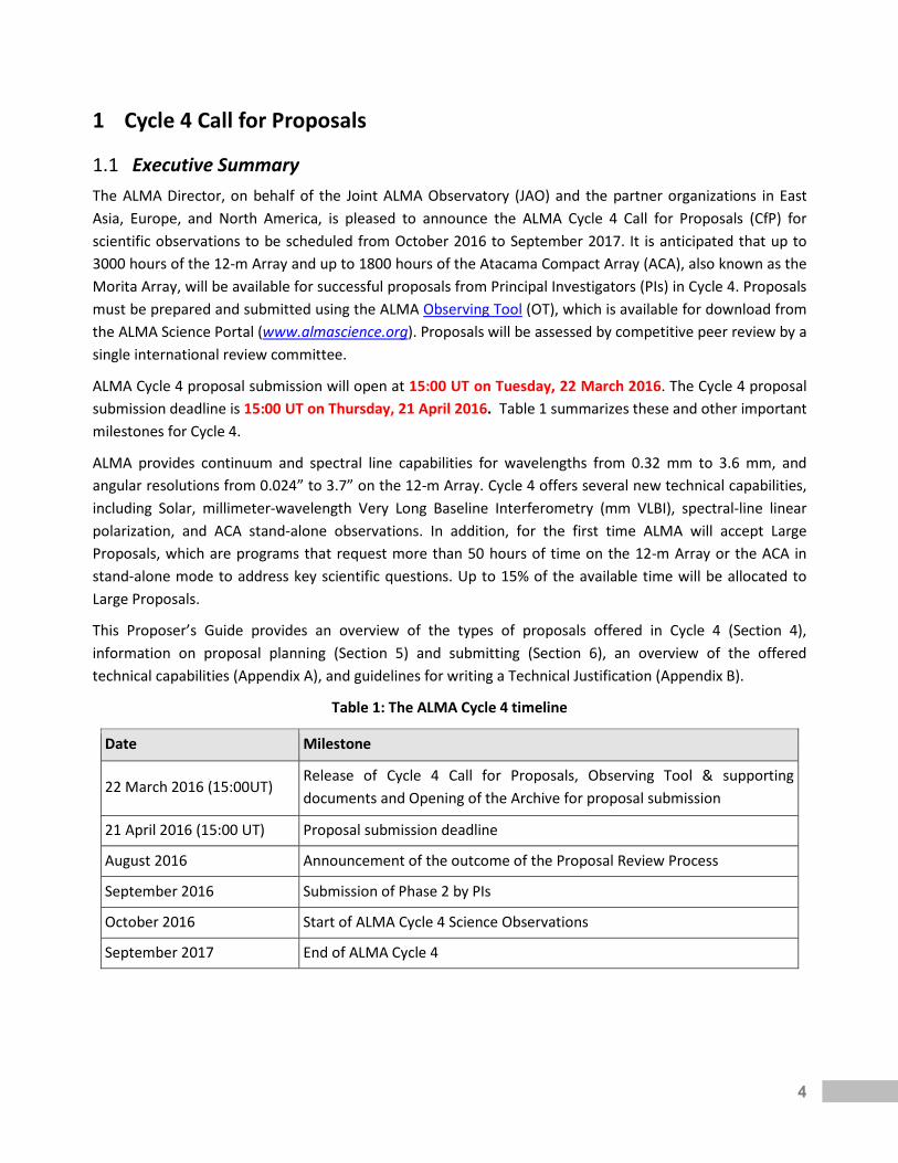
Executive Summary 1.1The ALMA Director, on behalf of the Joint ALMA Observatory (JAO) and the partner organizations in East Asia, Europe, and North America, is pleased to announce the ALMA Cycle 4 Call for Proposals (CfP) for scientific observations to be scheduled from October 2016 to September 2017. It is anticipated that up to 3000 hours of the 12-m Array and up to 1800 hours of the Atacama Compact Array (ACA), also known as the Morita Array, will be available for successful proposals from Principal Investigators (PIs) in Cycle 4. Proposals must be prepared and submitted using the ALMA Observing Tool (OT), which is available for download from the ALMA Science Portal (www.almascience.org). Proposals will be assessed by competitive peer review by a single international review committee.
ALMA Cycle 4 proposal submission will open at 15:00 UT on Tuesday, 22 March 2016. The Cycle 4 proposal submission deadline is 15:00 UT on Thursday, 21 April 2016. Table 1 summarizes these and other important milestones for Cycle 4.
ALMA provides continuum and spectral line capabilities for wavelengths from 0.32 mm to 3.6 mm, and angular resolutions from 0.024” to 3.7” on the 12-m Array. Cycle 4 offers several new technical capabilities, including Solar, millimeter-wavelength Very Long Baseline Interferometry (mm VLBI), spectral-line linear polarization, and ACA stand-alone observations. In addition, for the first time ALMA will accept Large Proposals, which are programs that request more than 50 hours of time on the 12-m Array or the ACA in stand-alone mode to address key scientific questions. Up to 15% of the available time will be allocated to Large Proposals.
This Proposer’s Guide provides an overview of the types of proposals offered in Cycle 4 (Section 4), information on proposal planning (Section 5) and submitting (Section 6), an overview of the offered technical capabilities (Appendix A), and guidelines for writing a Technical Justification (Appendix B).
Table 1: The ALMA Cycle 4 timeline
Date Milestone
22 March 2016 (15:00UT) Release of Cycle 4 Call for Proposals, Observing Tool & supporting documents and Opening of the Archive for proposal submission
21 April 2016 (15:00 UT) Proposal submission deadline
August 2016 Announcement of the outcome of the Proposal Review Process
September 2016 Submission of Phase 2 by PIs
October 2016 Start of ALMA Cycle 4 Science Observations
September 2017 End of ALMA Cycle 4
5
The ALMA Science Portal 1.2The ALMA Science Portal is the primary access point to ALMA for science users. It provides a gateway to all ALMA resources, documents and tools relevant to users for proposal preparation, proposal assessment, project tracking, project data access and data retrieval, as well as access to the ALMA Helpdesk.
From the Science Portal, anyone can:
• Register as an ALMA user • Access ALMA user documentation and software tools, including the ALMA Sensitivity Calculator,
observing simulators, and Splatalogue. the ALMA spectral line database • Download the OT • Access Helpdesk “knowledgebase” articles, which provide answers to common questions • Access non-proprietary data from the ALMA archive
In addition, registered users may:
• Manage their user profile, including the option to receive automatic email notifications of observing progress or delegate their data rights to other ALMA users
• Access SnooPI, the tool for PIs to monitor the status of their scheduled observing projects • Submit Helpdesk tickets • Access their proprietary data through the science archive
To ensure full-time availability, there are three instances of the Science Portal, one at each ARC. Users may access any of them via a common entry point at http://www.almascience.org.
The Science Portal also includes links to the local ARC webpages from which users can access local information and specific services of each ARC, such as local visitor and student programs, schools, workshops, and outreach materials and activities.
ALMA Proposal Eligibility 1.3Users of any professional background, nationality or affiliation may submit an ALMA proposal. All proposals are evaluated on the basis of scientific merit and technical feasibility. ALMA uses a panel-based proposal review system to ensure that scientifically knowledgeable peers representing the broad diversity of the community at large provide expert and non-discriminatory proposal evaluations. ALMA believes that inclusiveness and broad representation of the users’ community produces the most compelling scientific program.
Each proposal must have a PI who is responsible for the scientific outcome and administrative conduct of the project. The PI will act as the official contact between ALMA and the proposing team for all correspondence related to the proposal. Large Proposals may designate any number of co-PIs who will share scientific responsibility for the project. Any other individuals who are actively involved in any proposal may be designated as co-Is. There is no limit to the number of co-PIs or co-Is who may appear on a proposal.
Additional rules apply for qualification to use the Chilean share of the time and they are described at http://www.das.uchile.cl/das_alma_crc.html. These rules include the timely submission of supporting documentation to the ALMA Chilean Review Committee.

6
ALMA policies prohibit multiple submissions of the same proposal using different Executive affiliations. If such proposals are detected, the first submitted version will be considered and the remaining proposals ignored.
2 What’s New in Cycle 4 This section summarizes significant changes made in Cycle 4. Additionally, any changes, clarifications, or bugs that are discovered after the publication of this Proposer’s Guide are documented in the following Knowledgebase Article:
https://help.almascience.org/index.php?/Knowledgebase/Article/View/327
All proposers should check this article regularly, especially just prior to submitting their proposals.
New Proposal Types and Observing Modes 2.1The new proposal types and observing modes that will be offered in Cycle 4 are listed below. Details on these proposal types and observing modes are given in Section 4 and Appendix A, respectively, with supplemental technical material given in the Cycle 4 Technical Handbook.
Large Programs
Large Program proposals are expected to address strategic scientific issues that cannot be addressed with a series of smaller proposals. They are defined as proposals that request more than 50 hours of observations with either the 12-m Array or the ACA in stand-alone mode.
Millimeter-wavelength VLBI Proposals
Proposals for Very Long Baseline Interferometry (VLBI) observations with ALMA in Bands 3 and 6 will be accepted. In addition to submitting an ALMA proposal, VLBI programs must also submit a proposal to the appropriate VLBI network according to their deadlines.
ACA stand-alone observing mode
Proposals to observe using the ACA in a stand-alone capacity for short baseline interferometry and single-dish observations will be accepted for the first time. Proposals to use the TP Array in a stand-alone capacity are not permitted.
Solar observing mode
Proposals will be accepted for ALMA interferometric and single-dish observations of the Sun at selected frequencies in Bands 3 and 6.
Spectral line polarization
Full polarization observations using high spectral resolution correlator modes and arbitrary tunings are now allowed. Polarization proposals are still restricted to compact sources observed in Bands 3, 6 or 7. Only linear polarization is an accepted observing mode. While PIs will receive data which will allow them to generate circular polarization data, the quality and/or accuracy of that data at this time is not assured, and such data should not be used for scientific purposes.

7
New Proposal Requirements 2.2Education and Public Outreach paragraph
A paragraph describing the potential for publicity of the proposed observation is no longer required. Instead, the delivered package for successful observations will include contact information for the regional public outreach teams, who can help project teams publicize their results.
Proposal duplications
The criteria used to determine if a proposed observation is a duplication of a previous or scheduled observation have been modified (see Section 5.4).
Standard & non-standard observing modes
As in previous cycles, each Science Goal (SG) of a proposal will be classified as a “standard” or “non-standard” observing mode (see Section 5.2). New non-standard observing modes in Cycle 4 include spectral line polarization, Solar observations, and mm-VLBI. New standard mode observations include long baseline observations (baselines > 5 km) in Bands 3, 4, and 6.
12-m Array representative configurations
The 12-m Array “representative” configurations have been updated to reflect a minimum of 40 Array Elements, and maximum baselines ranging from 155 m to 12.6 km.
New OT Features 2.3The OT had a very large number of updates for this cycle. Some of the more notable changes for Cycle 4 include:
• There is a new field in the “proposal” tab to list the project code for uncompleted Cycle 3 proposals that are being resubmitted for Cycle 4
• The restriction that each SG be limited to targets that are within 10 degrees on the sky and need no more than five tunings has been removed. However, multiple SBs will be generated in Phase 2.
• The data rate that triggers a warning has been increased to 40 MB/s • The need for ACA in concert with 12-m Array observations is based entirely on the user-specified
“Largest Angular Structure in source”, and cannot be deselected
3 ALMA Overview
The ALMA Partnership 3.1ALMA, an international astronomy facility, is a partnership of the European Organization for Astronomical Research in the Southern Hemisphere (ESO), the U.S. National Science Foundation (NSF) and the National Institutes of Natural Sciences (NINS) of Japan in cooperation with the Republic of Chile. ALMA is funded by ESO on behalf of its Member States, by NSF in cooperation with the National Research Council of Canada (NRC) and the National Science Council of Taiwan (NSC) and by NINS in cooperation with the Academia Sinica (ASIAA) in Taiwan and the Korea Astronomy and Space Science Institute (KASI). ALMA construction

8
and operations are led by ESO on behalf of its Member States; by the National Radio Astronomy Observatory (NRAO), managed by Associated Universities, Inc. (AUI), on behalf of North America; and by the National Astronomical Observatory of Japan (NAOJ) on behalf of East Asia. JAO provides the unified leadership and management of the construction, commissioning and operation of ALMA.
The ALMA Telescope 3.2ALMA is composed of 66 high-precision antennas. Fifty of these antennas are 12-meter dishes in the 12-m Array, used for sensitive, high-resolution imaging. The remaining sixteen antennas make up the ACA, used to enhance wide-field imaging: twelve of those are closely spaced 7-meter antennas (7-m Array), and four are 12-meter antennas for single-dish observations (Total Power Array). The wavelengths currently covered by ALMA range from 0.32 mm to 3.6 mm (frequency coverage of 84 GHz to 950 GHz).
The Array is located on the Chajnantor plain of the Chilean Andes at latitude = −23.029°, longitude = −67.755°. The site offers the exceptionally dry and clear sky conditions required to operate at millimeter and submillimeter wavelengths. The ALMA antennas, weather stations, the two correlators and their computer interfaces, Local Oscillator generation hardware, timekeeping hardware, and the related Array Real-Time Machine computer are all located at the 5000-meter site referred to as the Array Operations Site (AOS). This site is connected via Gigabit fiber links to the Operation Support Facility (OSF), located at an altitude of 2900 meters, not far from the town of San Pedro de Atacama. Science operations are conducted from the OSF and coordinated from the Joint ALMA Observatory (JAO) Central Office in Santiago.
A detailed description of the ALMA technical characteristics is found in the ALMA Technical Handbook .
The Joint ALMA Observatory and the ALMA Regional Centers 3.3The JAO is responsible for the overall leadership and management of construction and operations of ALMA in Chile. The Santiago Central Office (SCO) houses the Director's Office and its associated functional units, as well as astronomers, technicians and administrative staff. The SCO also hosts the ALMA main archive (referred to in the rest of this document as the Archive). The JAO solicits proposals to observe with ALMA through Calls for Proposals and organizes the peer review of the proposals by science experts. In addition, the JAO schedules all science observations and places the data in the electronically accessible ALMA Archive.
The three Executives maintain the ARCs within their respective region. The ARCs provide the interface between the ALMA project and its user communities. The ARCs are responsible for user support, mainly in the areas of proposal preparation, observation preparation, acquisition of data through the Archive, data reduction, data analysis, data delivery, face-to-face visitor support and workshops, tutorials, and schools. Each ARC operates an archive that is a mirror of the SCO Archive. Browsing and data mining are done through the ARC mirror archives.
The East Asian ARC (EA ARC) is based at the National Astronomical Observatory of Japan (NAOJ) headquarters in Tokyo. It is operated in collaboration with Academia Sinica Institute of Astronomy and
9
Astrophysics (ASIAA) in Taiwan and Korea Astronomy and Space Science Institute (KASI) in Korea and supports the astronomy communities of Japan, Taiwan1 and Republic of Korea.
European researchers are supported by the European ARC (EU ARC). It is organized as a coordinated network of scientific support nodes distributed across Europe. The EU ARC is located at ESO Headquarters in Garching bei München (Germany), where also many of the ARC activities take place. Face-to-face support and additional services are provided by seven regional nodes and one centre of expertise. The regional nodes are currently: Bonn-Cologne (Germany), Bologna (Italy), Onsala (Sweden), IRAM, Grenoble (France), Allegro, Leiden (The Netherlands), Manchester (United Kingdom) and Ondřejov (Czech Republic). The centre of expertise is located in Lisbon (Portugal).
The North American ARC (NA ARC) is contained within the North American ALMA Science Center (NAASC), based at NRAO headquarters in Charlottesville, VA, USA. It is operated in collaboration with the National Research Council of Canada (Canada) and Academia Sinica Institute of Astronomy and Astrophysics (Taiwan), and supports the astronomical communities of North America and Taiwan1.
4 Proposal Types
Regular Proposals 4.1Regular Proposals refer to observations that can be fully specified by the regular proposal submission deadline and whose estimated execution time does not exceed 50 hr on the 12-m Array or on the ACA in stand-alone mode. Regular Proposals may include standard or non-standard modes and may involve time critical, multiple epoch observations, and the monitoring of a target over a fixed time interval.
Time-critical observations requiring a time window smaller than 14 days will not be guaranteed, but will be attempted on a best effort basis. This should not prevent observations of recurring phenomena with predictable times (e.g. maximum elongations of planetary satellites), as long as their occurrences are spread over a sufficiently wide fraction of the Cycle 4 observing period and as long as the number of epochs that need to be observed remains relatively small with respect to the total number of suitable epochs across the cycle (i.e., there are several possible time slots for each observation). Any special timing constraints (e.g. observations that, once started, need to be continued for a set amount of time or executed with a fixed cadence) must be fully justified, both scientifically and technically.
Target of Opportunity (ToO) Proposals 4.2ToO Proposals should be submitted to observe targets that can be anticipated but not specified in detail. Like Regular Proposals, these proposals must be submitted by the Cycle 4 proposal deadline and may include standard or non-standard modes. While the target list may be left unspecified, observing modes and sensitivity requests must be specified in detail for ToO observations. For each triggered SG the proposal should specify the number of triggers needed, what the triggers will be, and the necessary reaction time for scheduling the observation after it is triggered.
1 Support of the Taiwanese astronomical community is shared by the EA and NA ARCs.
10
The Observatory will attempt to observe ToO proposals during the 48 hours following their triggering provided the appropriate scheduling conditions (mainly weather and antenna configuration, see Section 5.3) are met. However, critical activities of the Observatory such as engineering and activities associated with the optimization and further development of the Array will not be interrupted (if ongoing at the time of triggering) to carry out ToO observations. Consequently, reaction times may be significantly longer if the triggering occurs shortly before or during one of those activities. PIs will trigger observations from accepted ToO Proposals through the ToO triggering web form available at the ALMA Science Portal.
Large Programs 4.3Large Programs are proposals with an estimated execution time of greater than 50 hours on the 12-m Array (with or without accompanying ACA time) or on the ACA in stand-alone mode. Large Program proposals must include only standard modes (as defined in Section 5.2) and should not involve time-critical or Target of Opportunity observations.
A Large Program proposal should address strategic scientific issues leading to a breakthrough in the field, be a coherent science project, not reproducible by a combination of Regular Proposals, lead to high level archival data products, and contain a solid management plan ensuring an efficient utilization of the data, including analysis and organization of the efforts.
The program teams will be expected to deliver their proposed data products and documentation describing the data products to ALMA within 1 year of the final delivery of calibrated data. The data products and documents will be made available to the community at large. ALMA will publish in due time the standards for product naming, product metadata and product quality that the successful program teams will have to adhere to. The program teams will work with representative ARCs to ensure that the standards are met.
Large Programs may designate any number of co-PIs, who share the overall responsibility with the PI in conducting the proposed science, however only the PI has the responsibility for SBs preparation and approval, and the delivery of the data products in accordance with the ALMA Users’ Policies. The requested observing time will be split among the regions (North America, Europe, East Asia, and Chile) based on the proportionality of the Executive affiliation of the PI and co-PIs (see Section 6.5.3).
The proposal team for a Large Program should not in parallel submit a Cycle 4 Regular Proposal that requests to do part of the science requested in the Large Program. Therefore, PIs, co-PIs and coIs of a Large Program cannot be a PI or a coI on a Cycle 4 Regular Proposal that duplicates observations (see Section 5.4) of their Large Program.
A maximum of 15% of the time available for science observations will be dedicated to the execution of Large projects, corresponding to 450 hours of 12-m Array time and 270 hours of ACA stand-alone time (Section 5.1). To optimize the success in completing the observations within Cycle 4, the following scheduling constraints will be imposed when selecting Large Programs: (1) the time allocated to Large Programs shall not exceed 33% of the available time for a given LST range on antenna configurations with baselines longer than 5 km (see Section 5.3.3); and (2) the time allocated to Large Programs shall not exceed 50% of the available time for a given LST range on configurations with baselines shorter than 5 km.

11
mm-VLBI Proposals 4.4VLBI observations with ALMA in Bands 3 and 6 will be offered for the first time in Cycle 4. ALMA VLBI proposals will be made in concert with the following VLBI networks: the Global Millimeter VLBI Array (GMVA) at 3 mm and the new NRAO/Event Horizon Telescope Consortium (EHTC) network at 1.3 mm. In addition to submitting an ALMA proposal, VLBI programs must also have submitted a proposal to the appropriate VLBI network by their respective deadlines: 1 February 2016 for the GMVA network and 28 April 2016 (23:59 UT) for the NRAO/EHTC.
For VLBI proposals only, the proposal may be submitted on behalf of a consortium by registering the consortium (e.g., EHT Consortium) as a registered user in the Science Portal. Members of the science team should be listed as a co-Investigator through the OT. The scientific justification should stipulate who are the “co-PIs” and how the time should be allocated to the regions.
ALMA-specific VLBI considerations are given in Section A.12 of this document. Further details on submitting 3 mm VLBI proposals to the GMVA are available from http://www3.mpifr-bonn.mpg.de/div/vlbi/globalmm/. Further detail on submitting 1 mm VLBI proposals to NRAO/EHTC is available from https://science.nrao.edu/observing/call-for-proposals/1mm-vlbi-cycle4/.
Up to 5% of the ALMA Cycle 4 observing time will be allocated to VLBI proposals, and VLBI Large Programs and DDT proposals are not permitted. As the time dedicated to VLBI observations will thus be scarce, proposals should include a quantitative justification as to why ALMA is essential for the goals of the project.
VLBI observations that include ALMA will occur in March/April 2017 while ALMA is in a relatively compact antenna configuration (Section 5.3.3), with up to thirty-seven 12-m antennas in the phased array.
Director Discretionary Time (DDT) Proposals 4.5DDT Proposals may be submitted at any time during Cycle 4 for execution during this cycle. To qualify for DDT usage, proposals must fulfill the conditions specified at http://almascience.org/proposing/ddt-proposals. Capabilities, time tolerance restriction, and science assessment will be based on the same criteria as for Regular and ToO Proposals. DDT Proposals will be considered for approval by the ALMA Director, based on the advice of a Standing Review Committee, with members from the JAO and the four regions, appointed by the Executive Directors and Chile. In exceptional cases, the ALMA Director may approve projects that would benefit from a very rapid response, and inform the Standing Committee and science operations team of this decision within 24 hours. Further DDT policies are described in the Users’ policies.
5 Proposal Planning
Time Available in Cycle 4 5.1Cycle 4 will have a duration of ~12 months, starting in 2016 October and finishing in 2017 September.
It is anticipated that up to 3000 hours of the 12-m Array and up to 1800 hours of the ACA will be available for successful proposals of Principal Investigator (PI) programs. An additional 150 hours on the 12-m Array and 90 hours on the ACA will be available for DDT proposals. The remaining time is allocated to activities such as observatory calibrations needed for PI observations, and includes weather and technical downtime

12
as well as engineering, computing and scientific test time to extend and optimize ALMA capabilities. A maximum of 20% of the available time can be allocated to non-standard observing modes, which are listed in Section 5.2. Furthermore, Large Programs and VLBI observations are limited to a maximum of 15% and 5% (respectively) of the available time (see Sections 4.3 & 4.4).
Summary of Capabilities Offered in Cycle 4 5.2The Cycle 4 capabilities are described in Appendix A. In summary they are:
Number of antennas • Forty (40) antennas in the 12-m Array • Ten (10) 7-m antennas (for short baselines) and three (3) 12-m antennas (for making single-dish
maps) in the ACA Receiver bands
• Receiver Bands 3, 4, 6, 7, 8, 9, & 10 (wavelengths of about 3.1, 2.1, 1.3, 0.87, 0.74, 0.44, and 0.35 mm, respectively)
12-m Array Configurations • Nine configurations with maximum baselines from 155 m to 12.6 km • Maximum baselines of 3.7 km for Bands 8, 9 and 10 • Maximum baselines of 6.8 km for Band 7 • Maximum baselines of 12.6 km for Bands 3, 4, & 6 • Files containing representative antenna configurations for both the 12-m and 7-m Arrays suitable for
CASA simulations are available from the ALMA Science portal (http://almascience.org/documents-and-tools/cycle4/alma-configuration-files)
Spectral line, continuum, and mosaic observations • Spectral line and continuum observations with the 12-m Array and the 7-m Array in all bands • Single field interferometry (all bands) and mosaics (Bands 3 to 9) with the 12-m Array and the 7-m
Array • Single-dish spectral line observations in Bands 3 to 8
Polarization • Single pointing, on axis, full polarization capabilities for continuum and full spectral resolution
observations in Bands 3, 6 and 7 on the 12-m Array
Cycle 4 observing modes are classified as standard or non-standard. Standard modes have been well characterized and the observations can be calibrated with the ALMA data reduction pipeline. Non-standard modes are not as well characterized and require manual calibration by ALMA staff. The Cycle 4 non-standard modes include:
• Bands 8, 9 & 10 observations • Band 7 observations with maximum baselines > 5 km • All polarization observations • Spectral Scans • Bandwidth switching projects (less than 1GHz aggregate bandwidths over all spectral windows) • Solar Observations • VLBI observations • Non-standard calibrations (user-defined calibrations selected in the OT)

13
Scheduling Considerations 5.3Cycle 4 observations will be scheduled during nighttime in 16 h shifts and three to four days a week during daytime, interrupted by periods of engineering and computing activities as well as execution of tasks associated with optimization and further development of the array.
This section describes the most important scheduling considerations that investigators should be aware of when preparing their ALMA proposal.
5.3.1 Scheduling Priority Apart from time-constrained observations (including Solar and mm-VLBI observations), there are other aspects of a proposed observation that will affect when it may be scheduled. In rough order of priority, those aspects are:
• weather conditions • requested angular resolution and Largest Angular Structure (LAS) • target elevation and other practical constraints • the projects’ assigned priority group in the order: Cycle 3 Grade A, Cycle 4 Grade A, Cycle 4 Grade B,
Cycle 4 Grade C • Solar and VLBI observations will be executed in a “campaign mode”, during specific dates scheduled
when the 12-m Array is in one of the three most compact 12-m Array configurations (see Section 5.3.3). During these campaigns, these observations will have priority.
• In the ACA observing queue, ACA observations that complement 12-m Array observations will have priority over ACA stand-alone observations
• Executive balance All things being equal, the project with the highest scientific rank will be observed.
5.3.2 Weather Considerations Chajnantor is one of the best sites in the world for ground-based observations in the (sub)millimeter wavelength range (Evans et al 2002, ALMA Memo No. 471, available from the ALMA Memo Series). However, both the opacity (primarily determined by the amount of Precipitable Water Vapour – PWV) and the phase stability of the atmosphere limit when ALMA can be used at certain frequencies, in particular in the higher-frequency bands and at frequencies near water absorption lines. Both transmission and phase stability follow a yearly cycle (late southern winter is best – see Figures 2 and 4 of Memo 471) and a diurnal cycle (late night and early morning are best – see Figures 3 and 5 of Memo 471). In addition to the transmission and phase stability criteria, the low wind speeds that typically occur during night and early morning provide optimum observing conditions.
These cycles are illustrated in Figure 1, which shows the fraction of the year when the PWV is below 1 mm. Red and blue colors represent low and high probability of good weather, respectively.

14
Regular weather patterns are subject to both short (daily) and longer cycles (years; the El Niño Southern Oscillation may be important). During parts of the year, such as the Altiplanic winter2 season (January-March), it may be difficult to carry out submillimeter observations. For this reason, a yearly extended maintenance and upgrade period is scheduled each February, during which no science observations are scheduled.
2 During southern summer, the high-pressure system over the Pacific Ocean weakens and moves southwards, allowing warm humid air from the Amazons to flow over the Andes into northern Chile, causing rain and occasionally snow to fall on the usually dry Altiplano: this phenomenon is known as Altiplanic winter.

15
Figure 1. The percentage of time when the Precipitable Water Vapour (PWV) is below 1 mm as a function of Local Sidereal Time (LST) and week number beginning with January 1. Red identifies epochs with very little time available at low PWV and therefore less suitable for high frequency observing, while blue corresponds to epochs with a large fraction of time available at low PWV. The data were obtained with the APEX radiometer over the years 2007-2011 (5 years). The diagonal thin dark grey lines show local midnight, and the diagonal thick light grey bands show the ALMA engineering time (day time), which for 3-4 days per week is shared with PI observations. The vertical dark grey band shows the February period devoted to annual maintenance and upgrades.
16
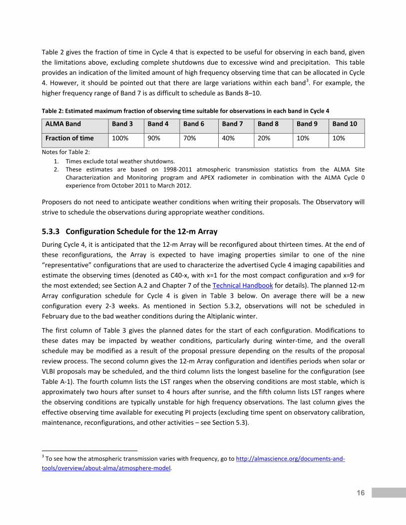
Table 2 gives the fraction of time in Cycle 4 that is expected to be useful for observing in each band, given the limitations above, excluding complete shutdowns due to excessive wind and precipitation. This table provides an indication of the limited amount of high frequency observing time that can be allocated in Cycle 4. However, it should be pointed out that there are large variations within each band3. For example, the higher frequency range of Band 7 is as difficult to schedule as Bands 8–10.
Table 2: Estimated maximum fraction of observing time suitable for observations in each band in Cycle 4
ALMA Band Band 3 Band 4 Band 6 Band 7 Band 8 Band 9 Band 10
Fraction of time 100% 90% 70% 40% 20% 10% 10%
Notes for Table 2: 1. Times exclude total weather shutdowns. 2. These estimates are based on 1998-2011 atmospheric transmission statistics from the ALMA Site
Characterization and Monitoring program and APEX radiometer in combination with the ALMA Cycle 0 experience from October 2011 to March 2012.
Proposers do not need to anticipate weather conditions when writing their proposals. The Observatory will strive to schedule the observations during appropriate weather conditions.
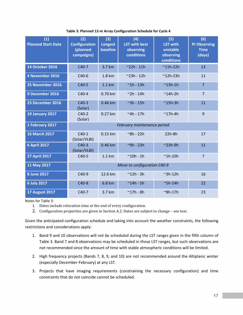
5.3.3 Configuration Schedule for the 12-m Array During Cycle 4, it is anticipated that the 12-m Array will be reconfigured about thirteen times. At the end of these reconfigurations, the Array is expected to have imaging properties similar to one of the nine “representative” configurations that are used to characterize the advertised Cycle 4 imaging capabilities and estimate the observing times (denoted as C40-x, with x=1 for the most compact configuration and x=9 for the most extended; see Section A.2 and Chapter 7 of the Technical Handbook for details). The planned 12-m Array configuration schedule for Cycle 4 is given in Table 3 below. On average there will be a new configuration every 2-3 weeks. As mentioned in Section 5.3.2, observations will not be scheduled in February due to the bad weather conditions during the Altiplanic winter.
The first column of Table 3 gives the planned dates for the start of each configuration. Modifications to these dates may be impacted by weather conditions, particularly during winter-time, and the overall schedule may be modified as a result of the proposal pressure depending on the results of the proposal review process. The second column gives the 12-m Array configuration and identifies periods when solar or VLBI proposals may be scheduled, and the third column lists the longest baseline for the configuration (see Table A-1). The fourth column lists the LST ranges when the observing conditions are most stable, which is approximately two hours after sunset to 4 hours after sunrise, and the fifth column lists LST ranges where the observing conditions are typically unstable for high frequency observations. The last column gives the effective observing time available for executing PI projects (excluding time spent on observatory calibration, maintenance, reconfigurations, and other activities – see Section 5.3).
3 To see how the atmospheric transmission varies with frequency, go to http://almascience.org/documents-and-tools/overview/about-alma/atmosphere-model.
17
Table 3: Planned 12-m Array Configuration Schedule for Cycle 4
(1) Planned Start Date
(2) Configuration
(planned campaigns)
(3) Longest baseline
(4) LST with best
observing conditions
(5) LST with unstable
observing conditions
(6) PI Observing
Time (days)
14 October 2016 C40-7 3.7 km ~22h - 11h ~11h-22h 13
4 November 2016 C40-6 1.8 km ~23h - 12h ~12h-23h 11
25 November 2016 C40-5 1.1 km ~1h - 13h ~13h-1h 7
9 December 2016 C40-4 0.70 km ~2h - 14h ~14h-2h 7
23 December 2016 C40-3 (Solar)
0.46 km ~3h - 15h ~15h-3h 11
19 January 2017 C40-2 (Solar)
0.27 km ~4h - 17h ~17h-4h 9
1 February 2017 February maintenance period
16 March 2017 C40-1 (Solar/VLBI)
0.15 km ~8h - 22h 22h-8h 17
6 April 2017 C40-3 (Solar/VLBI)
0.46 km ~9h - 23h ~23h-9h 11
27 April 2017 C40-5 1.1 km ~10h - 1h ~1h-10h 7
11 May 2017 Move to configuration C40-9
8 June 2017 C40-9 12.6 km ~12h - 3h ~3h-12h 16
6 July 2017 C40-8 6.8 km ~14h - 5h ~5h-14h 22
17 August 2017 C40-7 3.7 km ~17h - 8h ~8h-17h 23
Notes for Table 3: 1. Dates include relocation time at the end of every configuration. 2. Configuration properties are given in Section A.2. Dates are subject to change – see text.
Given the anticipated configuration schedule and taking into account the weather constraints, the following restrictions and considerations apply:
1. Band 9 and 10 observations will not be scheduled during the LST ranges given in the fifth column of Table 3. Band 7 and 8 observations may be scheduled in those LST ranges, but such observations are not recommended since the amount of time with stable atmospheric conditions will be limited.
2. High frequency projects (Bands 7, 8, 9, and 10) are not recommended around the Altiplanic winter (especially December-February) at any LST.
3. Projects that have imaging requirements (constraining the necessary configuration) and time constraints that do not coincide cannot be scheduled.
18
As can be seen from this table, the Cycle 4 plan is to be in extended configurations during the 2017 austral winter (June – August, when longer periods suitable for high frequency observing are expected). In Cycle 5 the array configuration schedule will complement this plan, such that compact configurations will be scheduled for the 2018 austral winter, and the extended configurations will be scheduled at different months compared to Cycle 4.
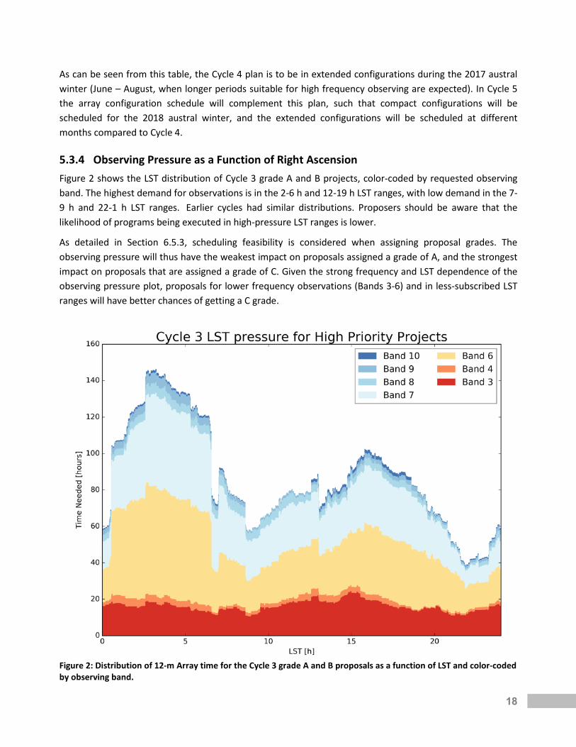
5.3.4 Observing Pressure as a Function of Right Ascension Figure 2 shows the LST distribution of Cycle 3 grade A and B projects, color-coded by requested observing band. The highest demand for observations is in the 2-6 h and 12-19 h LST ranges, with low demand in the 7-9 h and 22-1 h LST ranges. Earlier cycles had similar distributions. Proposers should be aware that the likelihood of programs being executed in high-pressure LST ranges is lower.
As detailed in Section 6.5.3, scheduling feasibility is considered when assigning proposal grades. The observing pressure will thus have the weakest impact on proposals assigned a grade of A, and the strongest impact on proposals that are assigned a grade of C. Given the strong frequency and LST dependence of the observing pressure plot, proposals for lower frequency observations (Bands 3-6) and in less-subscribed LST ranges will have better chances of getting a C grade.
Figure 2: Distribution of 12-m Array time for the Cycle 3 grade A and B proposals as a function of LST and color-coded by observing band.

19
Duplicate Observations and Resubmissions 5.4
5.4.1 Checking for Duplications In order to ensure the most efficient use of ALMA, duplicate observations of the same location on the sky with similar observing parameters (frequency, angular resolution, coverage, and sensitivity) are not permitted unless scientifically justified. Archival data should be used whenever possible to accomplish the science goals of a proposed investigation. Observations are considered duplicates if the conditions indicated in Section 5.4 and Appendix A of the Users’ Policies are met.
It is the responsibility of the proposers to check the proposed observations against the catalog of previously executed or accepted programs to avoid duplicate observations. Proposed targets should be checked against the list of prior and scheduled observations provided by the JAO. This list will include observations obtained in previous cycles (with the exception of Cycle 0), Cycle 3 Grade A projects, and any Cycle 3 projects with data deliveries that occur before the Cycle 4 proposal submission deadline. Proposers will not be penalized for proposing duplications of previous cycle observations if they had no way to know about them by the proposal deadline. See the Duplications link on the Science Portal for information on checking for duplications.
Any proposed duplicate observation must be justified within the Scientific Justification of the proposal. PIs are also advised to justify their proposed observations in cases where they are similar to previously executed or accepted programs but are not formal duplicates. The ALMA Review Panels will determine if the requested duplicate observation is scientifically justified.
5.4.2 Resubmission of an Unfinished Proposal Proposal teams that submit a Cycle 4 proposal to observe some or all science goals of a currently active but unfinished project should identify their Cycle 4 proposal as a “Resubmission” by entering the proposal code in the Resubmission field in the OT. For such resubmissions, the relevant portion of the Cycle 4 proposal will be cancelled or descoped if the observations are successfully completed by the end of Cycle 3. The Scientific Justification in the Cycle 4 proposal should clearly indicate which science goals are resubmissions. A scientific justification must be provided if the proposers deem the Cycle 4 observations necessary even if the observations are completed in Cycle 3; the APRC will decide if such resubmissions are accepted.
Estimated Observing Time 5.5Proposal requests are cast in terms of Science Goals, each specifying a desired sensitivity, angular resolution, and Largest Angular Structure (LAS) to be obtained for a set of sources and a given spectral setup. These are used to estimate a total observing time to reach the goals (except for Solar or VLBI observations or when over-ridden by the PI - see Appendix B). This observing time is the sum of the required time-on-source for all science targets, time for all calibrations including overheads, and the time for any additional array configurations needed to meet the specified LAS. The estimated observing time for the proposal is the sum of the times for all Science Goals. The actual observing time to reach a given sensitivity, resolution and LAS will depend on the prevailing conditions when the project is observed and the actual Array configuration(s) used (number of elements and distribution of baselines).

20
The estimated time-on-source is calculated from the ALMA Sensitivity Calculator (ASC), available within the OT or as a stand-alone application on the Science Portal. The parameters that affect these time estimates include source declination, observing frequency, spectral bandwidth, number of antennas, angular resolution (if the sensitivity is specified in temperature units) and default weather conditions. A description of the ALMA Sensitivity Calculator is given in Chapter 9 of the ALMA Cycle 4 Technical Handbook. The time-on-source is subject to a minimum of 10 seconds per pointing, and a minimum of 2 minutes for all sources in a Science Goal (see Section 5.3.5.3 of the OT Users Manual). If the total time-on-source(s) is more than 50 minutes, the OT determines that additional executions of the same observing commands, or Scheduling Block (SB), need to be executed. The number of required executions is based on the total time on all sources calculated by the ASC.
Each SB needs a complete set of calibrations. The calibration times and overheads are based on the number of calibrators of each type, and the default dwell times, duty cycles, and overheads, all of which are frequency and configuration dependent. These times are calculated per SB, and the total calibration time is this value times the number of SB executions to reach the required on-source sensitivity.
The final factor in the time estimate is the time for any additional configurations needed to supplement the configuration that best matches the requested angular resolution in order to also reach the specified LAS (see Table A-1 in Section A.2). The LAS is compared to the “Maximum Recoverable Scale” (MRS) of the configuration that best matches the requested angular resolution (MRS are also listed in Table A-1). If the LAS is larger, then additional configurations, if allowed, are added with a time estimated using the multipliers given in Table A-2. This process repeats as required. If the array combinations are not allowed (see Section A.4), the OT will give a validation error. Note that stand-alone ACA observations are selected when the requested angular resolution corresponds to that of the 7-m Array.
The PI may add additional Science Goals for array combinations not allowed in a single science goal, but each SG must be separately justified and have its own performance goals (sensitivity, angular resolution, and LAS). Data from each SG will be processed, assessed, and delivered independently. Combining the data from the different Science Goals will be left to the investigators.
When calculating the time required for ACA, the OT uses the TP Array time if this array is required (based on LAS) or otherwise the 7-m Array time; i.e., it is not the sum of the 7-m and TP Array time.
The results of these calculations are reported in the Science Goal “Time Estimate” in the OT.
The total time required by a proposal is estimated in the OT by adding the expected observing times for both the 12-m Array and the ACA. The times for the 12-m Array and ACA and total time are tabulated separately on the proposal coversheet, since each has its own proposal queue and time allocation. To be approved, a proposal must fit into the time allotment of the appropriate queues.
21
Supporting Tools and Documentation 5.6
5.6.1 The Observing Tool Documentation The ALMA OT is the proposal preparation and submission (Phase 1) software application; the OT is also used for observation preparation (Phase 2). The OT documentation suite provides all the basic information required to complete the steps of proposal preparation and submission. It includes:
• The OT Phase 1 Quickstart Guide: A guide to proposal preparation for the novice ALMA OT user. It provides an overview of the necessary steps to create an ALMA Observing Proposal.
• The OT Video Tutorials: A visual demonstration of proposal preparation and submission with the OT.
• The OT User Manual: This manual is intended for all ALMA users, from novices to experienced users. It provides comprehensive information about how to create valid Phase 1 proposals and Phase 2 programs for observing astronomical objects. It is also included as part of the “Help” documentation within the OT application itself.
• The OT Reference Manual: This manual provides a more concise explanation for all the fields and menu items in the OT. It is also included as part of the “Help” documentation within the OT application itself.
• The OT trouble-shooting page lists OT installation requirements and workarounds for common installation problems.
• The known OT issues page lists currently known bugs, their status and possible workarounds. This page may be updated during the proposal submission period, so if you experience problems with the OT please check here first.
5.6.2 Proposal Preparation Utilities There are two tools to help users produce simulated images of ALMA observations of simple or user-provided science targets. A guide for simulating ALMA observations with either tool is available at http://casaguides.nrao.edu/index.php?title=Guide_To_simulating_ALMA_Data.
The first simulation tool is integrated into CASA (Common Astronomy Software Applications), the offline data reduction and analysis tool for ALMA data. CASA includes the tasks “simobserve” and “simanalyze”, which generate simulated ALMA data and make images from the simulations. An additional CASA task, “simalma”, simplifies the process of combining data from multiple arrays. These CASA tools require configuration files that specify the outlay of ALMA antennas. Files for representative Cycle 4 configurations are available at the Science Portal (http://almascience.org/documents-and-tools/cycle4/alma-configuration-files). Additional information on CASA, including hardware requirements and download instructions, is available at http://casa.nrao.edu.
The second simulation tool is the ALMA Observation Support Tool (OST). The OST uses a simplified web interface to help users generate ALMA simulations. Users submit jobs to the OST and are notified by email when the simulations are completed. The OST documentation is available at http://almaost.jb.man.ac.uk/help.

22
Splatalogue is a database containing frequencies of atomic and molecular transitions emitting in the radio through submillimeter wavelength range. This database is used by the ALMA OT for spectral line selection. To learn more about it, see the Splatalogue QuickStart Guide on the Science Portal.
The atmospheric transmission at the ALMA site can be investigated with the Atmosphere Model tool, which allows the user to model the atmospheric transmission as a function of frequency and amount of PWV. The output is a plot of the transmission fraction as a function of frequency. Up to six different water vapour levels can be selected.
5.6.3 The ALMA Regional Center Guides The ARC Guides contain user support details specific to each ALMA regional partner. They are:
• The East-Asian ARC Guide
• The European ARC Guide
• The North American ARC Guide
5.6.4 Supplemental Documentation The following documents supplement this Proposers Guide for the preparation of Cycle 4 proposals, for either the novice or advanced users. All documents can be accessed via the ALMA Science Portal (http://almascience.org/documents-and-tools).
The Proposing Guidance link from the science portal offers users succinct summaries of the successive steps involved in the preparation and submission of an ALMA observing proposal. It is designed to help users to find the relevant documents and sources of additional information in each step easily.
Observing with ALMA: A Primer is a brief introduction to ALMA observing, to submillimeter terminology, and to interferometric techniques, that should prove useful for investigators who are new to radio astronomy. Several example science projects illustrating the Cycle 4 capabilities are also provided.
The ALMA Users’ Policies document contains a complete description of the applicable users’ policies. The long-term core policies for usage of ALMA and of ALMA data by the user community are presented.
The ALMA Cycle 4 Technical Handbook describes the more technical details of ALMA during Cycle 4, including but not limited to receiver characteristics, array configurations, available observing modes and correlator setups, and the basis of the OT time estimates.
The ALMA Memo Series and ALMA Technical Notes Series include technical reports on various aspects of ALMA project development and construction and from the extension and optimization of capabilities team.
The ALMA Helpdesk 5.7The ALMA Helpdesk is accessed from the ALMA Science Portal or directly at http://help.almascience.org. Submitted tickets are directed to one of the ARCs, where support staff are available to answer any question related to ALMA, including but not limited to ALMA policies, capabilities, documentation, proposal preparation, the OT, Splatalogue, and CASA. Users may also request information on workshops, tutorials, or
23
about visiting an ARC or ARC node for assistance with data reduction and analysis. Users must be registered at the ALMA Science Portal to submit a Helpdesk ticket. Generally, ALMA staff aim to answer Helpdesk tickets within two working days.
The “knowledgebase feature” of the Helpdesk is a database of answered questions or articles on all aspects of ALMA and is also available to unauthenticated users. Users can search the knowledgebase to find answers to common queries without submitting a Helpdesk ticket. Knowledgebase articles that match their query are automatically suggested to users as they type.
6 Proposal Preparation and Submission
Proposal Format 6.1An ALMA proposal consists of basic proposal information that is entered directly into the ALMA OT, a Science Justification uploaded to the OT as a PDF file, and one or more Science Goals.
The OT is a Java-based application that resides and runs on the user's computer and is used for proposal preparation and submission (“Phase 1”) and, in the event that the proposal is awarded time, for the detailed planning of the observations (“Phase 2”).
Science Goals contain the technical details of the proposed observations and must include a Technical Justification. The OT is designed to facilitate proposal preparation and includes a number of tools and checks to ensure submitted proposals conform to the Cycle 4 capabilities.
After entering the basic proposal information and completing the Science Goals in the OT, the PI can generate the PDF including all the proposal information (including Science Goals and Scientific Justification) that will be distributed to the ALMA Proposal Review Committee for evaluation.
The following sections contain guidelines for preparing the Science and Technical Justification parts of a proposal. The setup of Science Goals is only briefly explained and users are referred to the extensive suite of OT documentation for details (Section 5.6.1). ALMA novices are encouraged to start with the OT Quickstart Guide and the video tutorials.
Preparing the Scientific Justification 6.2ALMA Cycle 4 proposals must include a single PDF document that includes a science case written in English. The document may optionally include figures, tables and references.
6.2.1 Page and Size Limits The total length of the PDF document is limited to 4 pages for Regular, ToO, Solar and mmVLBI proposals and to 6 pages for Large Program proposals (A4 or US Letter format), with a font size no smaller than 12 points. The recommended breakdown is 2 pages for the science case and 2 pages for figures, tables, and references, but proposers are free to adjust these numbers within the overall page limit. Large proposals are allowed an additional 2 pages to describe the management plan and data products. Figures and tables may be interleaved with the science case, so that they appear close to the location in the text where references are made to them. Although the Technical Justification for each Science Goal is entered in the OT, any figure

24
required for it needs to be placed in the Science Justification PDF document. Users are encouraged to use the LaTeX template developed by ALMA for preparation of their proposals (available at http://almascience.org/documents-and-tools/cycle4/alma-proposal-template).
A file size limit of 20 MB will be enforced at submission. Proposals must be self-contained. Their assessment will be based solely on their explicit contents, and no external references will be considered. Reference can be made to published papers (including astro-ph preprints), as per standard practice in the scientific literature. Consultation of those references should not, however, be required for understanding the proposal.
6.2.2 Science Case Each proposal must describe the astronomical importance of the proposed project and include a clear statement of its immediate observing goals. Additionally, it should explain how the expected intensity of the target source(s) was estimated and justify the Signal-to-Noise (S/N) ratio required to achieve the scientific objectives of the project as well as, when appropriate, the size of the target sample.
Proposers can simulate ALMA observations using different array components and configurations (see Section 5.6.2). Simulations are not required. However, if they are discussed in a proposal to justify any technical aspects of an observation, their results (i.e., images and simulation details) should be included in the science case and referenced in the relevant Technical Justification. Proposers should keep in mind that the fields of expertise of individual members of the ALMA Review Panels span a wide range of scientific areas. Therefore, proposals should be written for an expert, but also be broad-based in order to satisfy a wider astronomy audience.
6.2.3 Figures, Tables, and References Figures, tables, and references that support the science case and the Technical Justification may be included. Figure captions, tables and references may use 10-point font and, together with the science case, they must fit within the overall page length and 20 MB size limits of the PDF proposal.
Preparing the Science Goals 6.3
6.3.1 Technical Setup The Science Goals (SGs) contain the complete observational setups: spatial coordinates and imaging characteristics, frequency band, spectral windows and spectral resolutions, sensitivity requirements and integration time for one or more science targets.
The OT Quickstart Guide and the OT User Manual provide extensive details and guidance to prepare the Science Goals and Scheduling Blocks. Experienced users who wish to understand how ALMA observations are set up are referred to Chapter 8 of the Technical Handbook.
6.3.2 Technical Justification All proposals must contain a Technical Justification, which is entered directly into the OT in the Technical Justification (TJ) node of each SG. Any figures associated with the TJ must be included in the Science
25
Justification PDF file and clearly referenced in the TJ. Except for the figures, the TJ must be self-contained, and there should be no expectation or requirement that the technical assessor reads the scientific justification for details. Note that while the requested sensitivity or S/N, source size, and source sample size should be justified in the Scientific Justification (Section 6.2.2), the means by which such values will be achieved with the proposed technical setup must be included in the TJ (see Appendix B). An incomplete Technical Justification may lead to the rejection of the proposal on technical grounds.
Each SG has its own Technical Justification since the technical setup of the observations will often vary substantially from one SG to the next. If a Technical Justification is applicable to more than one SG, the TJ node can be easily copied and pasted between SGs. The TJ node contains three main sections – sensitivity, imaging, and correlator configuration - corresponding to the main aspects that need to be addressed in order to assess the technical feasibility of any proposal. Each section includes at least one free-format text box that must be filled (50 characters minimum), as well as a number of parameters computed from the user input captured in that Science Goal. This information is designed to help with the writing of the Technical Justification, and will also highlight potentially problematic setups (blue text) if applicable. Please see the relevant sections in the OT Reference Manual (accessible by clicking the “?” symbols within the OT) for details. If the OT detects any technical choices that require an extra justification, appropriately labeled text boxes will appear in an additional "Choices to be justified" section.
Given that the information and the text boxes displayed in the TJ node are dependent on information provided elsewhere in the SG (including the Expected Source Properties entered in the Field Setup node), the rest of the Science Goal should be set up before filling in the Technical Justification. Specific guidelines on filling out the Technical Justification are given in Appendix B. Please also see the ALMA OT video tutorial 4: “The technical justification”.
If a proposal does not conform to the advertised capabilities, it can be declared technically infeasible either during proposal review process or during Phase 2. The final decision will be made by the ALMA Director based on the advice from a standing committee consisting of senior staff at the JAO.
Proposal Validation, Submission and Withdrawal 6.4Once the proposal is validated within the OT, it can be submitted to the ALMA Archive. A proposal can be resubmitted by the PI as many times as needed before the proposal deadline, in which case the resubmitted proposal overwrites the previous version (see Section 6.4.1). Modifications of submitted proposals will not be permitted after the deadline. For DDT proposals the first submission is final.
Submission of Regular, ToO, Large and mm-VLBI Proposals will be available starting 15:00 UT on 22 March 2016 and will be accepted through the proposal deadline of 15:00 UT on 21 April 2016. The proposal submission deadline is firm and proposals cannot be received after the deadline because the archive will be closed.
PIs, co-Is and co-PIs can retrieve proposals from the Archive both before and after the deadline. However, to ensure that the load on the server does not affect its performance close to proposal submission deadline, users should refrain from unnecessarily retrieving proposals from the Archive between 0:00 and 15:00 UT on 21 April 2016.

26
If successfully submitted, a proposal receives a unique code adhering to a standard format, as follows: YYYY.C.NNNNN.X. Here, “YYYY” denotes the year, “C” is the cycle ID, “NNNNN” is a five-digit running number and “X” denotes the proposal type (“S” for Regular proposals, “T” for ToO, “V” for VLBI, and “L” for Large). For example, the code 2015.1.00156.S indicates a Regular proposal which is the 156th ALMA proposal submitted for the regular cycle in 2015. To allow for later re-submission, it is essential that, after submitting a proposal, users save a copy of it to their local disk, complete with the proposal submission code.
Cycle 4 DDT Proposals may be submitted anytime throughout the cycle. Like all other Proposals, they must include a full science case and a detailed Technical Justification.
A Helpdesk ticket should be submitted if the PI needs to withdraw a proposal after a code has been assigned.
6.4.1 Proposal Updates To update a previously submitted proposal, users should modify that saved, post-submission copy, to ensure that the same submission code is used. Alternatively, users could download the submitted proposal from the archive and modify that copy for resubmission. Attempts to update a previously submitted proposal using the local copy without a code should always be avoided, as this will result in a new (duplicate) submission that will be assigned a new code.
Users wishing to create a new proposal based on a previous one as a template should make sure to take as starting point a local copy without a code, so as to avoid overwriting their original proposal in the Archive.
Proposal Evaluation and Selection 6.5
6.5.1 Peer Review ALMA programs in Cycle 4 will be selected through competitive peer review. The reviewers consist of scientists selected from the international astronomical community with (sub)millimeter and topical expertise as well as a broader range of backgrounds including theory, multi-wavelength observations, numerical simulations, and/or instrumentation. The reviewers are assigned to individual ALMA Review Panels (ARPs) that are specialized in a scientific category. The ALMA Proposal Review Committee (APRC) consists of the chairs of each ARP and a Chair who is selected from the international community by the ALMA Director.
The JAO assigns each submitted proposal to a panel based primarily on the science category selected by the Principal Investigator on the proposal coversheet, but with care taken to avoid conflicts of interest with the ARP members.
The categories of review panels in Cycle 4 are:
1. Cosmology and the high redshift universe 2. Galaxies and galactic nuclei 3. Interstellar medium, star formation and astrochemistry 4. Circumstellar disks, exoplanets and the Solar system 5. Stellar evolution and the Sun

27
Cycle 4 proposers must further specify the area of investigation to which their project pertains by selecting in the OT at least one and at most two keywords from the list in Appendix D.
The output from each ARP is a ranked list of Regular and ToO proposals based on the review criteria indicated in Section 6.5.2. The ARPs will also review the Large Proposals assigned to their panel and recommend which proposals should be forwarded to the APRC for further review.
The APRC will review the ARP results to recommend resolution of proposals that request to observe the same sources with a similar observational setup. The APRC will also review Large Proposals and recommend which to schedule after taking into consideration the balance of time, science areas, overlap with ongoing programs, and technical and scheduling feasibility. The APRC will then merge the results from all panels to produce a final ranked-ordered list of proposals. The APRC Chair will forward the recommendations of the APRC to the ALMA Director.
6.5.2 Evaluation Criteria The primary criteria to rank all proposals is the overall scientific merit of the proposed investigation and its potential contribution to the advancement of scientific knowledge. A Large Proposal in particular should address strategic scientific issues leading to a breakthrough in the field.
Given the significant investment of ALMA resources, the rank of Large Proposals will also be based on the following criteria:
1) Technical feasibility A Large Proposal should fully justify the requested sensitivity, the correlator setup, and the imaging requirements. The observations should be consistent with observatory best practices unless justified in the proposal.
2) Scheduling feasibility A Large Proposal should be designed such that the observations can likely be completed within Cycle 4 given the antenna configuration schedule and weather constraints (see Section 5.3).
3) Data products A Large Proposal should describe the data products that will be produced to achieve their science goals. The program teams will be expected to deliver these data products to the ALMA Regional Centers (ARCs) so that they can be made available to the community at large.
4) Management plan A Large Proposal should present a management plan that describes a schedule of work, a description of the roles of the proposal team, and a plan to disseminate the results.
6.5.3 Proposal Selection The JAO will take the recommendations of the APRC and form an observing queue based primarily on the scientific ranking from the APRC, but taking also into account the scheduling constraints dictated by the configuration schedule and weather, the share of observing time for each region and a 20% limit on total time allocated to proposals that include non-standard modes.

28
The shares of the observing time among the regions are:
1. 33.75% for the European Organization for Astronomical Research in the Southern Hemisphere (ESO) 2. 33.75% for the National Science Foundation of the United States (NSF) 3. 22.5% for the National Institutes of Natural Sciences of Japan (NINS) 4. 10% for the Chilean community, which is administrated jointly by CONICYT and the Universidad de
Chile.
All regions contribute toward “Open Skies” to enable all eligible Principal Investigators to apply for ALMA time.
Accepted proposals will be assigned letter grades of A, B, or C and will move forward to Phase 2 preparations (Section 7.1). Grade A proposals have the highest priority, followed by Grade B and then Grade C (see Section 5.3 for all scheduling considerations). Only Grade A are eligible to be rolled over to Cycle 5, if necessary.
Grades are assigned based on science rank, Executive balance, and scheduling feasibility. Up to 33% of the nominal time specified in Section 5.1 will be assigned to Grade A proposals and 67% to Grade B proposals. The total time assigned to Grade A and B proposals will correspond to the nominal number of hours indicated in Section 5.1.
Grade C will be assigned to non-grade A and B proposals up to an additional 50% of the nominal available time, in order to ensure that an adequate number of projects are available for all configurations and LST in case the actual observing efficiency or weather conditions differ from expectations.
Grade assignments are subject to the following restrictions:
1. VLBI proposals are not eligible for receiving a Grade A or Grade C. 2. Large Proposals must receive a Grade A in order to be scheduled. 3. Once the Grade A+B time cap for either the 12-m Array (3000 hr) or the ACA time (1800 hr) is
reached, no more proposals requesting both 12-m Array and ACA time may receive a Grade A or B. 4. It is unlikely that proposals needing Band 7 daytime observations will be assigned a Grade C. 5. Non-standard proposals are not eligible for receiving a Grade C.
Proposal Confidentiality 6.6For proposals assigned Grade A or B, the project code, the proposal title and abstract, the name and region of the PI, as well as the names of the co-Is (and co-PIs, if existent) will be made public soon after PIs are informed of the outcome of the proposal review process. For proposals assigned Grade C, the corresponding information will be made public as soon as its first data are archived.
Proposal metadata (for example the source positions, observation frequencies, and integration times) for Grade A proposals will be made public soon after the PIs are informed of the outcome of the proposal review process. The metadata for Grade B and C proposals will be made public as soon as the first data are archived. The metadata for unaccepted proposals or unobserved Grade B or C proposals will remain confidential.
The scientific and technical justifications of all submitted proposals remain confidential.

29
PI Notification 6.7After the outcome of the Proposal Review Process is approved by the ALMA Director’s Council, the results will be communicated to the PIs of submitted proposals. The notifications will include information about its assigned grade, and a consensus report from the ALMA review panels intended to help PIs identify weaknesses and strengths of their proposals.
7 Post-proposal Activities
Observations Preparation and Submission: Phase 2 7.1Once a project has been approved for scheduling, the project passes into Phase 2. First, changes resulting from the proposal review process or necessitated by technical considerations will be implemented by the ALMA staff. Then, the project is assigned back to the PI to confirm the observing parameters and submit the project for scheduling. The PI may request the help of an ALMA Contact Scientist (CS) at the associated ARC or ARC node, by submitting a Helpdesk ticket.
Necessary minor changes to the project may also be implemented at this stage, as long as they do not impact the science scope or increase the total execution time. Any change that is more significant must be requested through the Helpdesk (see below) and is generally discouraged.
Once PI has prepared the Phase 2, the PI approves it by submitting using the “submit” bottom in the OT. ALMA staff will check the correctness and the feasibility and in case of problems will contact the CS and the PI. Otherwise, the project is approved and admitted to the ALMA observing queue to await actual execution at the telescope. PIs may track the status of their SBs through the PI tool SnooPI, accessible from the ALMA Science Portal.
For successful Solar observations that were submitted using a dummy ephemeris file (Section A.11), the ALMA Observatory will coordinate with PIs to get an updated target ephemeris at least 24 hours in advance of the proposed observation.
Changes to Submitted Projects 7.2Changes to a submitted project will not be permitted prior to the completion of the review process. Changes to a project accepted for admission to the ALMA observing queue, unless minor (see above), will not normally be permitted. Therefore, PIs should carefully check source coordinates, frequency and angular resolution settings and calibration needs before submitting their proposal and use Helpdesk if they need support.
Major change requests are only fully justified if additional information that may seriously affect the scientific case of the project has become available since the time of submission, when there is a demonstrable bona fide mistake, or when there is the potential for interesting scientific optimization. Change requests are made through the ALMA Helpdesk. The request must include a very clear description of the proposed change along with a clear, substantive justification for the change. Major change requests are treated case-by-case and evaluated taking into account increase in science scope, change of observing time, change from a

30
standard to a non-standard mode etc. Change requests leading to duplications against current or past ALMA proposals will not be approved.
Data Processing and Data Delivery 7.3ALMA staff will conduct quality assurance on ALMA data, and will provide processed data products through the respective ARCs. See Chapter 11 of the ALMA Technical Handbook for a more complete description of the QA2 Process.
QA2 is performed on the data that result from all executions of an SB (called an ObsUnitSet or OUS), or on a collection of OUSs that are combined. Data that meet the PI-specified goals within cycle-specific tolerances are marked “QA2 Pass” and are made available to the PI. The tolerances adopted for Cycle 4 are: achieved sensitivities within 10% of the PI request for Bands 3 – 6, within 15% for Bands 7 – 8, and within 20% for Bands 9 – 10; angular resolutions within 30% of PI request. See the Technical Handbook for full details.
Once the data are ready for delivery, the PI is notified by the ARC which the PI is registered and the PI can download such data from the ALMA archive after authentication at the ALMA Science Portal. PIs are requested to check the delivered data as soon as practical. If the delivered data have problems, PIs need to submit a QA3 request to the Helpdesk as soon as possible, since this will have implications for the re-observation of problematic data and its proprietary period (see Sections 8.4.3 and 8.4.4 of the ALMA Users’ Policies document).
By default, data obtained as part of an ALMA science program are subject to a proprietary period of 12 months (except DDT programs, which have a 6-month proprietary period), starting for each data package when the ARC sends the notification to the PI that the data are available.
Opportunities for Public Promotion of ALMA 7.4If the PI believes their results are newsworthy or of interest to a broader community, the PI should contact the ALMA Education and Public Outreach (EPO) team to develop materials for presentation to the media and the public (e.g. press releases), including support in the preparation of visuals if relevant. EPO may ask for cooperation on the scientific content and for the PI to be available for possible interviews. The e-mail address for the ALMA EPO team is [email protected].
31
ALMA Cycle 4 Capabilities Appendix AThis appendix describes the characteristics and capabilities of the ALMA Observatory that are offered for the Cycle 4 observing season. All submitted proposals must be compliant with these capabilities or they will be judged as infeasible. Where possible, the ALMA Observing Tool has validation checks to warn or prevent entering un-allowed values.
A.1 Number of Antennas In Cycle 4 at least forty 12-m antennas in the main array (hereafter the 12-m Array) will be offered. The ACA will have available at least ten 7-m antennas (hereafter the 7-m Array) for short baselines and three 12-m antennas (hereafter the Total Power or TP Array) for making single-dish maps. The ACA will be offered both to complement observations with the 12-m Array as well as a stand-alone capability. The use of the TP Array is limited to spectral line observations (not continuum) in Bands 3, 4, 6, 7 and 8. Bands 9 and 10 are not available for any TP observations.
The number of antennas available may sometimes be less than the numbers given above due to unforeseen problems with the equipment, or during array reconfigurations. ALMA support staff will endeavor to schedule observations that will not be seriously affected by having a slightly smaller number of antennas. The integration times or uv-coverage might also be increased to compensate whenever this is practical.
A.2 Array Configurations As detailed in Section 5.5, a science goal is defined in terms of a desired angular resolution and the Largest Angular Structure (LAS) to be imaged. ALMA will meet these requirements by taking observations in one or more array configurations, which are characterized in terms of their Angular Resolution (AR) and Maximum Recoverable Scale (MRS, the largest smooth angular structure than can be imaged without too much degradation – see Chapter 7 of the Cycle 4 Technical Handbook for details). The properties of these configurations, and the allowed combinations, therefore define the imaging capabilities of ALMA.
In Cycle 4 the antennas in the 12-m Array will be staged into distinct configurations intended to transition from the most compact (with maximum baselines of ~155 m) up to the most extended configuration (maximum baselines of ~12.6 km). Nine 12-m Array configurations have been defined to represent the possible distribution of 40 antennas over this range of maximum baselines. These are denoted as C40-x, with x=1 for the most compact configuration and x=9 for the most extended. One 7-m Array configuration has been defined to represent the possible distribution of the ten 7-m dishes. The imaging capabilities of these configurations are given in Table A-1.

32
Table A-1: Angular Resolutions (AR) and Maximum Recoverable Scales (MRS) for the Cycle 4 Array configurations
Config Lmax Band Band 3 Band 4 Band 6 Band 7 Band 8 Band 9 Band 10
Lmin Freq 100 GHz 150 GHz 230 GHz 345 GHz 460 GHz 650 GHz 870 GHz
7-m Array
45 m AR 12.5" 8.4" 5.4" 3.6" 2.7" 1.9" 1.4"
9 m MRS 66.7" 44.5" 29.0" 19.3" 14.5" 10.3" 7.7"
C40-1 155 m AR 3.7" 2.5" 1.6" 1.1" 0.80" 0.57" 0.42"
15 m MRS 29.0" 19.4" 12.6" 8.4" 6.3" 4.5" 3.3"
C40-2 273 m AR 2.4" 1.6" 1.0" 0.69" 0.52" 0.37" 0.27"
15 m MRS 22.1" 14.8" 9.6" 6.4" 4.8" 3.4" 2.5"
C40-3 460 m AR 1.5" 0.97" 0.63" 0.42" 0.32" 0.22" 0.17"
15 m MRS 13.7" 9.1" 5.9" 4.0" 3.0" 2.1" 1.6"
C40-4 704 m AR 0.93" 0.62" 0.40" 0.27" 0.20" 0.14" 0.11"
15 m MRS 8.9" 5.9" 3.9" 2.6" 1.9" 1.4" 1.0"
C40-5 1.1 km AR 0.54" 0.36" 0.23" 0.16" 0.12" 0.083" 0.062"
17 m MRS 6.0" 4.0" 2.6" 1.7" 1.3" 0.93" 0.69"
C40-6 1.8 km AR 0.35" 0.23" 0.15" 0.10" 0.076" 0.054" 0.040"
15 m MRS 3.1" 2.1" 1.3" 0.90" 0.67" 0.48" 0.36"
C40-7 3.7 km AR 0.21" 0.14" 0.090" 0.060" 0.045" 0.032" 0.024"
81 m MRS 1.8" 1.2" 0.77" 0.52" 0.39" 0.27" 0.20"
C40-8 6.8 km AR 0.12" 0.079" 0.052" 0.034" N/A N/A N/A 168 m MRS 1.3" 0.87" 0.57" 0.38"
C40-9 12.6 km AR 0.066" 0.044" 0.029" N/A N/A N/A N/A 271 m MRS 0.78" 0.52" 0.34"
Notes for Table A-1: 3. See Chapter 7 of the Technical Handbook for relevant equations and detailed considerations. 4. Values evaluated for source at zenith. For sources transiting at lower elevations, the North-South angular
measures will increase proportional to 1/sin(ELEVATION). 5. Lmax and Lmin are the maximum and minimum baseline lengths in the array. 6. All angular measures scale inversely with observed sky frequency. 7. Bold blue text indicates non-standard modes (Section 5.2)
A.3 Total Power Array The TP Array is used to recover extended emission when mapping angular scales up to the size of the requested map areas. For Cycle 4, TP Array observations are included only if the LAS cannot be achieved with the 7-m Array, and the TP Array can only be used for spectral line observations (not continuum) in Bands 3–8. No TP Array Band 9 and 10 observations are offered for this cycle. This means that angular scales greater than the 7-m Array MRS listed in Table A-1 cannot be recovered for any observations in Band 9 and 10, or for continuum observations in any band.

33
A.4 Allowed Array Combinations and Time Multipliers For Cycle 4, only certain array combinations are allowed to meet the specifications of a given science goal. An SG can use no more than two 12-m Array configurations, and 7-m Array observations are only allowed in conjunction with 12-m Array observations if one of the three most compact 12-m Array configurations is required. TP Array observations are allowed only if 7-m Array observations are also obtained (and subject to the restrictions in the preceding section). The allowed combinations are indicated in Table A-2 (with empty cells indicating combinations that are not allowed), and built into the OT validation.
For the resulting data to have good imaging properties, the different arrays must be observed in the correct proportion, depending on the number of overlapping baselines (see Chapter 7 of the Cycle 4 Technical Handbook for details). These are expressed in terms of multiplicative factors with respect to the time required in the most extended configuration (which in turn is set by the user requested sensitivity and resolution). The time multipliers adopted for Cycle 4 are given in Table A-2, and are reported in the OT.
Table A-2: Allowed Array Combinations and Time Multipliers
Most Extended
configuration
Allowed Compact configuration pairings
Extended 12-m Array
Multiplier
Multipler if compact 12-m Array needed
Multipler if 7-m Array needed
Multipler if TP Array needed and allowed
7-m Array TP
1 1.7
C40-1 7-m Array & TP 1
5 8.5
C40-2 7-m Array & TP 1
5 8.5
C40-3 7-m Array & TP 1
1.4 2.38
C40-4 C40-1 & 7-m Array & TP 1 0.3 3 5.1
C40-5 C40-2 & 7-m Array & TP 1 0.3 1.4 2.38
C40-6 C40-3 & 7-m Array & TP 1 0.3 0.4 0.68
C40-7 C40-4 1 0.3
C40-8 C40-5 1 0.3
C40-9 C40-6 1 0.3
Notes for Table A-2: 1. See Chapter 7 of the Technical Handbook for relevant equations and detailed considerations. 2. Whether a more compact array configuration is “needed” is based on the user specified LAS compared to the
MRS values corresponding to the more extended configuration, as listed in Table A-1. If the LAS is greater than the MRS of the extended configuration, a more compact configuration is needed. Conversely, if a more compact array configuration is not allowed (e.g. for 12-m Array configurations more extended than C40-6), the LAS is not obtainable and will result in a validation error in the OT.
During Phase 2 (Section 7.1), separate Scheduling Blocks (SBs) will be prepared for each required configuration. These will be observed independently, and the data from the different SBs will be calibrated and imaged separately.

34
A.5 Receivers Bands 3, 4, 6, 7, 8, 9 and 10 will be available on all antennas. However, observations with Bands 8, 9 and 10 will only be offered for configurations with baselines up to ~ 3.7 km, Band 7 up to ~ 6.8 km, and Bands 3, 4 and 6 up to ~ 12.6 km (see Section A.2).
There are two types of receivers: dual-sideband (2SB), where the upper and lower sidebands are separated in the receiver and then processed separately, and double-sideband (DSB), where the sidebands are super-imposed coming out of the receiver but may be separated in later processing. All bands receive dual linear polarizations (X and Y).
Table A-3 summarises the properties of the receiver bands offered in Cycle 4. Details can be found in Chapter 4 of the Technical Handbook.
Table A-3: Properties of ALMA Cycle 4 Receiver Bands
Band Frequency range1
(GHz) Wavelength range
(mm) IF range
(GHz) Type
3 84 – 116 3.6 – 2.6 4 – 8 2SB
4 125 – 163 2.4 – 1.8 4 – 8 2SB
6 211 – 275 1.4 – 1.1 5 – 10 2SB
7 275 – 373 1.1 – 0.8 4 – 8 2SB
8 385 – 500 0.78 – 0.60 4 – 8 2SB
9 602 – 720 0.50 – 0.42 4 – 12 DSB
10 787 – 950 0.38 – 0.32 4 – 12 DSB Notes for Table A-3:
1. These are the nominal frequency ranges for continuum observations. Observations of spectral lines that are within about 0.2 GHz of a band edge are not possible (at present) in Frequency Division Mode (FDM, see Section A.6.1), because of the responses of the spectral edge filters implemented in the correlator. IF is the intermediate frequency.
Although up to three receiver bands will be available at any time, the capability to rapidly switch between them within the same Science Goal (except for the purposes of data calibration) is not offered in Cycle 4.
Water Vapour Radiometer (WVR) measurements to correct for fluctuations in atmospheric water vapour will be available for all 12-m antennas. No WVRs are installed in the ACA 7-m antennas and no WVR corrections will be applied to 7-m Array observations.
Band 9 and 10 considerations
For Band 9 and 10 observations, additional uncertainties will affect the data. Since the sidebands can be separated reliably only in interferometric observations, single-dish Band 9 and 10 observations with the TP Array will not be offered in Cycle 4. Also, owing to the complexity of the atmospheric absorption in Bands 9 and 10, calibration will be compromised (this also applies to Band 8 and the high frequency end of Band 7). Band 9 and 10 ACA 7-m Array observations are more compromised than the corresponding 12-m Array observations, since the rapid atmospheric phase correction cannot be applied, and the smaller collecting

35
area will limit the network of usable calibrators; in particular, bright calibrators will be sparse at these high frequencies. All of these factors, together with the limited uv-coverage, will affect imaging at Bands 9 and 10 during Cycle 4 and will in particular limit the achievable dynamic range with the ACA 7-m Array. Imaging dynamic ranges up to 50 are typical for these bands (see Section A.9.1 for more details).
No mosaics will be offered for Band 10 observations.
A.6 Spectral Capabilities
A.6.1. Spectral Windows, Bandwidths and Resolutions The ALMA IF system provides up to four basebands (per parallel polarization) that can be independently placed within the two receiver sidebands. For 2SB receivers (Bands 3–8 – see Table A-3), the number of basebands that can be placed within a sideband is 0, 1, 2, 3, or 4. User cannot select 3 basebands in one sideband and 1 in the other, but 3 and 0 are fine. For DSB receivers (Bands 9 and 10), any number of basebands (up to 4) is acceptable.
The 12-m Array uses the 64-input Correlator, while the 7-m and TP Arrays use the 16-input ACA Correlator. Both correlators offer the same spectral setups. The 64-input Correlator operates in two main modes: Time Division Mode (TDM) and Frequency Division Mode (FDM). TDM provides modest spectral resolution and produces a relatively compact data set. It is used for continuum observations or for spectral line observations that do not require high spectral resolution. FDM provides high spectral resolution and produces much larger data sets. A total of six correlator setups with different bandwidths and spectral resolutions are available (see Table A-4).
Table A-4: Properties of ALMA Cycle 4 Correlator Modes, dual-polarization operation 1,2
Bandwidth
(MHz) Channel spacing(3)
(MHz) Spectral resolution
(MHz) Number of channels Correlator mode(4)
1875 15.6 31.2 120 TDM
1875 0.488 0.976 3840 FDM
938 0.244 0.488 3840 FDM
469 0.122 0.244 3840 FDM
234 0.061 0.122 3840 FDM
117 0.0305 0.061 3840 FDM
58.6 0.0153 0.0305 3840 FDM Notes for Table A-4:
1. These are the values for each spectral window and for each polarization, using the full correlator resources and no on-line spectral binning.
2. Single-polarization modes are also available, giving twice the number of channels per spw, and half the channel spacing of the above table.
3. The “Channel Spacing” is the separation between data points in the output spectrum. The spectral resolution – i.e., the FWHM of the spectral response function – is larger than this by a factor that depends on the “window function” that is applied to the data to control the ringing in the spectrum. For the default function – the “Hanning” window – this factor is 2. See the Technical Handbook for full details.
4. Only for the 64-input Correlator

36
For each baseband, the correlator resources can be divided across a set of “spectral windows” (spw) that can be used simultaneously and positioned independently. For Cycle 4, up to four spectral windows per baseband are allowed. The correlator can be set to provide between 120 and 3840 channels within each spw, and the fraction of correlator resources that are assigned to each spw sets the number of channels and the bandwidth available within it. The sum of the fractional correlator resources spread across all spectral windows must be less than or equal to one (3840 channels in total).
The data can be pre-smoothed in the correlator by averaging (or binning) spectral channels in powers of 2. This allows one to reduce the data rate without increasing the sampling integration time, at the expense of spectral resolution (see Chapter 5 of the Cycle 4 Technical Handbook for more information). In Cycle 4, the maximum data rate is 60 MB/s. For any spectral setup requiring an average data rate of more than 40 MB/s PIs will be contacted during Phase 2 to discuss the possibility to reduce the data rate.
Different correlator modes can be specified for each baseband, but all spws within a given baseband must use the same correlator mode. For example, a high-resolution FDM mode can be used for spectral line observations in one baseband (with up to 4 independently placed FDM spectral windows), while the other three basebands can be used for continuum observations using the low-resolution TDM mode. And while each spw within a baseband must use the same correlator mode, they can each be assigned a different fraction of the correlator resources and each use a different spectral averaging factor, providing a broad range of simultaneously observed spectral resolutions and bandwidths. Spectral windows can overlap in frequency, although the total continuum bandwidth for calculating the sensitivity is set by the total non-overlapped bandwidth.
A.6.2. Science Goals with more than one Tuning Users can include up to five tunings per sources in a single Science Goal, up to a maximum of 150 tunings (per SG). This enables spectral scans or observations of targets with different radial velocities within the same SB.
The current calibration scheme for ALMA is to make each SB self-contained in terms of calibration. Therefore, multi-tuning SGs result in bandpass, amplitude, and gain calibrators being observed for each tuning in the SB. For SBs that can be completed in a single execution, this is quite efficient. However, for SBs that require multiple executions, the available time for science targets in each execution is reduced, and the resulting SBs can be quite inefficient. Separating each tuning into its own Science Goal can lead to more efficient SBs and lower overall time estimates.
Spectral scan mode
A special case of the multiple tuning science goal is the Spectral Scan mode. This is useful for proposers who wish to carry out spectral surveys or redshift searches. The OT will automatically set up a set of contiguous spectral windows to cover a specified frequency range, provided that:
1. Angular resolution and LAS are computed for the Representative Frequency of each SG; 2. No more than 5 frequency tunings per target are used, all in the same band; 3. Only one pointing per target is used (no mosaics or offsets allowed);

37
4. In each SG the sum of the number of separate tunings required does not exceed 150 (i.e., the maximum number of targets with 5 tuning per target is 30);
5. Only 12-m Array observations are required (the ACA is not offered for this mode). 6. Full polarization is not selected
Spectral scans are categorized as a non-standard mode, limiting the total time available for such observations.
A.7 Polarization For Cycle 4, on top of the dual polarization (XX, YY) and single polarization modes (XX), observations to measure the full intrinsic polarization (XX, XY, YX and YY) of sources will also be offered for TDM and FDM observations in Bands 3, 6 and 7. Only linear polarization is an accepted observing mode. While PIs will receive data that will allow them to generate circular polarization data, the quality and/or accuracy of that data at this time is not assured, and such data should not be used for scientific purposes.
When a Dual Polarization setup is used, separate spectra are obtained for each linear parallel-hand polarization of the input signal. These will give two largely independent estimates of the source spectrum that can be combined to improve sensitivity.
In Single Polarization mode, only a single input polarization (XX) is recorded. For a given resolution, this provides √2 worse sensitivity than the Dual Polarization case, but one can use either a factor two more bandwidth for the same spectral resolution (unless the maximum bandwidth was already being used) or a factor of two better spectral resolution for the same bandwidth.
Full Polarization measurements using TDM and FDM modes will be offered in Cycle 4 for 12-m Array observations only in Bands 3, 6 and 7. This is a non-standard mode, limiting the total time available for such observations. Sources must be centered (no positional offsets allowed) and have a user-specified largest angular structure that is less than one-third of the 12-m Array primary beam at the frequency of the planned observations. The expected minimum detectable degree of polarization is 0.1%(1%) for compact sources and 0.3%(3%) for extended sources for TDM (FDM) observations, respectively. Observations must be single-field, but measurements of several individual sources within one Science Goal are possible (one field per source; see below). Full polarization is not offered in spectral scan mode. The frequency settings for continuum polarization measurements can be specified by the user, but the OT supplies default setups as detailed in Table A.5. For FDM mode polarization observations any frequency setting within Bands 3, 6 and 7 is allowed, and the spectral setup has to be the same for the polarization calibrator and the science target.
It should be noted that full polarization observations require about 3 hours of parallactic angle coverage for proper calibration. Science Goals with properties that lead to a total observing time estimate that is less than 3 hours will have the time estimate set to 3 hours to ensure sufficient parallactic angle coverage.

38
Table A-5: Default frequencies for Continuum Polarization Observations1
Band SPW1 (GHz)
SPW2 (GHz)
LO1 (GHz)
SPW3 (GHz)
SPW4 (GHz)
3 90.5 92.5 97.5 102.5 104.5
6 224.0 226.0 233.0 240.0 242.0
7 336.5 338.5 343.5 348.5 350.5 Notes for Table A.5 :
1. Fixed central frequencies for four TDM spectral windows, each of width 1.875 GHz, and the corresponding LO1 setting.
2. Frequencies were chosen to optimize spectral performance, and they are centered in known low noise and low instrumental polarization tunings of the receivers.
A.8 Source Restrictions Source positions are designated by: 1) fixed RA and DEC; 2) RA and DEC at epoch 2000.0 with a linear proper motion; or 3) An ephemeris that is specified that gives the RA and DEC as a function of time. All positions should be in ICRS (J2000).
At low elevations, it is possible for foreground array elements to block or “shadow” the signal received by background antennas, compromising the sensitivity and imaging characteristics of an observation (see the Section 7.3 of the Technical Handbook for details). Therefore, observations of high declination targets should be avoided. For the 12-meter array, this shadowing becomes significant (> 5 %) in the most compact configuration for sources with declination lower than −75° or higher than +25°. This effect is even more significant for the more compact 7-m Array, with significant shadowing for sources with declination less than −60° or greater than +20°. The adopted upper declination limit for ALMA is ~ +47 deg (corresponding to a maximum elevation of 20 degrees at the ALMA site) and the OT gives a warning for objects transiting between 20 and 30 degrees elevation (corresponding to ~+37-47 deg declination).
A.8.1. Source Science Goal Restrictions A single Science Goal (SG) is constrained to include one set of observational parameters that apply to all sources included in that goal. This includes a single angular resolution, sensitivity, Largest Angular Structure (LAS), and receiver band. There is no restriction on the number of Science Goals per proposal.
As of Cycle 4, there is no longer a restriction on the number of sources in a Science Goal (SG). For sources distributed widely in the sky the SG will be split by the OT into different “clusters”, each grouping all sources within 10 degrees. For each grouping, the total number of pointings must be less than or equal to 150. Pointings with the ACA, if used in concert with 12-m Array observations, do not count against this 150 pointing limit.
The sources in a SG are further subjected to the following restrictions:
1. All the sources in a SG must be defined by the same field setup – either all as rectangular fields, or all as individual positions
2. Sources must use the same spectral setup (relative placement and properties of spectral windows)

39
3. Each source can be observed with up to 5 tunings. For a given group of sources with positions within 10 degrees in the sky the same restriction applies as in Section A.6.2: the number of separate tunings cannot exceed 150 (i.e., the maximum number of targets, for 5 tuning for all targets in a SG, is 30)
A.8.2. Rectangular Field A rectangular field (also referred to as a mosaic) is specified by a field center, the length, width and orientation of the field, and a single spacing between the pointing centers. Observations are conducted using the “mosaic” observing mode. This repeatedly cycles through all the pointings in the mosaic so that the imaging characteristics across the map are similar.
The OT will set up a uniform mosaic pattern based on a user-specified pointing separation, and will calculate the time to reach the required sensitivity considering any overlap. Non-Nyquist spatial samplings are allowed. Sparser samplings must be justified in the technical justification. Individual mosaics will not be combined during post-processing.
If ACA observations are requested as part of a mosaic, then a corresponding 7-m Array mosaic will also be observed. If these include TP observations, the mosaic area(s) will be covered by the TP Array using on-the-fly mapping.
Multiple sources may be included inside a SG, each of which can have a differently sized rectangular field. The collection of mosaics is subject to the source SG restrictions given above.
A.8.3. Individual Pointings Individual pointings may include a mixture of sources with or without additional offset pointings, provided that they comply with the source SG restrictions given above.
Sets of offsets are designated either as a “Custom Mosaic” or a “PointingPattern”. Custom Mosaic offsets are observed as mosaics and no offset may be separated by more than one primary beam from all other pointings. The interferometric data will be combined in post-processing to produce a single image. If ACA observations are requested as part of a 12-m Array Science Goal, then the corresponding 7-m Array observations will be obtained using a Nyquist-sampled mosaic pattern that covers the 12-m Array pointings.
PointingPattern positions are not observed as mosaics, do not have a separation constraint and will not be combined to produce a single image. If ACA observations are requested as part of a 12-m Array Science Goal, then the corresponding 7-m Array observations will be obtained for each source and the same pointings that were defined for the 12-m Array will be used.
For both types of offsets, the OT does not consider the effect of overlapping pointings; users must take this into account when specifying the required sensitivity.
If the TP array is also required, each 12-m Array pointing must be defined as a custom mosaic or entered as an individual field source. In other words, multiple positions specified using the PointingPattern may not have an LAS that requires TP observations.

40
A.9 Calibration The ALMA Observatory has adopted a set of strategies to achieve good calibration of the data (see Chapter 10 of the Cycle 4 Technical Handbook). Requests for changes in these strategies will only be granted in exceptional circumstances and must be fully justified by the requester. Some flexibility exists in choosing the actual calibrator sources. The default option is automatic calibrator selection by the system at observing time. If users opt for selecting their own calibrators, justification will be needed. This may result in decreased observing efficiency and/or calibration accuracy. Science Goals that request user-defined calibration are considered ‘non-standard’ (see Section 5.2).
A.9.1. Imaging Dynamic Range The standard ALMA data reduction should be sufficient to produce images with dynamic ranges (peak continuum flux to map rms) up to ~100. Therefore, images of bright sources may end up being dynamic range limited rather than sensitivity limited. This situation may be improved for some sources (e.g. by using self calibration), but this cannot be guaranteed.
The ACA and the compact configurations of the 12-m Array offer about the same imaging dynamic range. For the more extended configurations, or the higher frequency bands (Band 9 and 10) the maximum imaging dynamic range will be closer to 50.
For more information please see the Knowledgebase article “What is meant by imaging dynamic range?”.
A.9.2. Flux Accuracy Absolute amplitude calibration will be based on observations of objects of known flux, principally Solar system objects. It is expected that the accuracy of the absolute amplitude calibration relative to these objects will be better than 5% for Bands 3 and 4. Calibration in the higher frequency bands is likely to be less accurate. The goal is for it to be better than 10% in Bands 6 and 7. Calibration at Bands 8, 9 and 10 will be challenging even at the 20% level owing to the high atmospheric opacity.
A.9.3. Bandpass Accuracy The detailed shape of the spectral response of the arrays during observations depends on many factors. This shape particularly affects projects that intend to observe spectral features that cover a significant fraction of a spw, and/or study faint spectral features in the presence of strong continuum. It has been determined that, for Cycle 4, projects that require spectral dynamic ranges (i.e., the desired signal-to-noise ratio per spectral resolution element), per observation execution, of up to 1000 for ALMA Bands 3, 4, and 6 and 500 for Bands 7, 8, 9 and 10 are feasible. Requests for higher accuracies may be rejected on technical grounds.
A.9.4. Total Power Calibration The intensity calibration for single-dish observations with the TP Array is made by using the Amplitude Calibration Device (ACD), which results in an intensity scale in terms of the corrected Rayleigh-Jeans antenna temperature TA
* (K). To combine the TP data with the interferometric data the intensity scale is converted from K to Jy. The conversion factor is a function of the observed frequency, half-power beam width, and aperture efficiency of the TP Array antennas. The latter two are derived from a single-dish calibration
41
observation close in time to, and associated with, the observations of the science targets. The overall accuracy for the total power calibration is about 5% at Bands 3, 4, 6 and 7, increasing to 15% at Band 8.
A.9.5. Astrometry The absolute positional registration of an ALMA image on the sky depends on the angular resolution and the quality of the phase calibration. For standard calibration, the typical image registration accuracy is ~(angular resolution)/20.0. This assumes that the phase calibrator has an accurate VLBI position of 0.002" or smaller. In general, the closer that the calibrator is to the target and the smaller the phase variations, the more accurate is the image registration.
For projects in which measuring the position of an object or its motion over a period of time is the main goal, recommendations for Cycle 4 are:
1. Confirm that a check source is included in the observations (some observations include these in the default calibration). This is a calibrator of known position, so its measured position after calibration is an indication of the astrometric accuracy of the observations.
2. The maximum astrometric precision possible is equal to the image resolution divided by the signal-to-noise of the peak of the emission. Choose your desired angular resolution and observing band accordingly.
3. However: if the astrometric precision needed is smaller than about 0.02" rms, then consider specifying user-defined calibration and including multiple phase calibrators distributed around the target to serve as check sources (to determine astrometric correction terms). The check sources will be processed through the standard calibration pipeline, but it is the PI’s responsibility to calculate and apply the astrometric correction terms.
More details and guidelines on ALMA astrometric observations are given in Chapter 10 of the Cycle 4 Technical Handbook.
A.10 Time-constrained Observations Observations of monitoring and time-constrained projects will be offered in Cycle 4 with a few restrictions:
• Observations must be done in only one 12-m Array configuration; the ACA is not offered for time-constrained observations
• Time-critical observations requiring a time window smaller than 14 days will not be guaranteed, but may be attempted on a best-effort basis. Whether or not such observations are technically feasible will be decided on a case-by-case basis. In particular, observations with strict timing constraints but many possible time windows may be feasible.
• Proposals that require Band 8 or better weather conditions for more than two hours continuously will be rejected on technical grounds. Observations with less stringent weather requirements are limited to three hours of continuous monitoring. The longest continuous observations allowed are 3 hours for Bands 3-7 and 2 hours for Bands 8-10.
42
A.11 Solar Observations Proposals will be accepted for ALMA interferometric and total power observations of the Sun in Cycle 4 with the following capabilities and restrictions:
• Solar observations will be conducted using a “campaign mode”, whereby specific dates are reserved for the execution of Solar programs so that Solar experts are available to help with program execution. Observing windows will be identified during the periods when the 12-m Array is in one of the three most compact configurations (maximum baselines less than 500 m; see configuration schedule in Section 5.3.3). The actual campaign dates will be set after the proposal review process. Time constraints can be specified only if they imply observation times within the “Solar campaign”.
• The interferometric component of Solar observations will be conducted using a special combined array comprising both 12-m and 7-m antennas (to ensure sufficient short-spacing information is observed), and will be processed with the 64-input Correlator (Section 5.1 of the Technical Handbook). Observations with only 12-m or only 7-m Arrays are not offered.
• To minimize shadowing of 7-m antennas, observations will be carried out between 10:00 and 17:00 CLT (13:00 UT and 20:00 UT).
• PIs will designate a desired angular resolution. This is restricted to the range provided by one of the three most compact 12-m configurations (see Section A.2).
• The Total Power component of Solar observations consists of fast-scanning mapping observations of the full Sun to recover the largest angular scales for interferometric observations. Proposals requesting only total-power single-dish observations will not be accepted.
• The TP observations will be taken contemporaneously with the interferometric observation. These observations will not be executed when the Sun is at elevations above 70⁰ because the required fast-scan azimuth slew speeds are too high. The time cadence of full-sun images obtained from total power observations is about 7 minutes for Band 3 and 10 minutes for Band 6.
• Proposers will specify their Solar target by providing an ephemeris file. This can be a dummy ephemeris for the purposes of a proposal (one is available from the OT “template library”). The ALMA Observatory will coordinate with successful PIs to get an updated target ephemeris at least 24 hours in advance of the proposed observation.
• Only proposals for continuum observations in Bands 3 and 6 will be accepted. For the interferometric observations these will be obtained using the low spectral resolution (TDM) mode (see Section A.6.1). The individual integration times for this mode are fixed to 2 seconds, and the frequencies are fixed to four 1875 MHz-wide spectral windows centered on the frequencies shown in Table A-6 below. The high spectral resolution (FDM) observing mode is not offered for Solar observations.
• The observing frequencies of the total power observations are as shown in Table A-6, but the total power data only include one channel per SPW; a correlator will not be used for total power observations in Cycle 4 and so autocorrelation measurements will not be available.

43
Table A-6: Observing Frequencies for Cycle 4 Solar observations
Band SPW1 (GHz)
SPW2 (GHz)
LO1 (GHz)
SPW3 (GHz)
SPW4 (GHz)
3 93.0 95.0 100.0 105.0 107.0
6 230.0 232.0 239.0 246.0 248.0
• Simultaneous observations with Bands 3 and 6 are not offered: each science goal can only include
one band.
• Observations may be performed using dual linear polarization (XX, YY) or single polarization (XX) correlations; full polarization measurements are not currently offered for Solar observations.
• Because the WVR receivers are saturated when the antennas point at the Sun, the on-line WVR phase correction will not be applied and the off-line WVR correction for on-source (Solar) data is not possible.
• Absolute calibration of single-dish brightness temperatures is currently no better than ~10% but is more realistically ~15%. While efforts are ongoing to improve Solar calibration, Cycle 4 science goals that require absolute temperatures more accurate than this, and in particular comparisons of absolute temperatures between Bands 3 and 6, will be difficult to carry out successfully.
• The total observing time requested for one proposal cannot exceed 50 hours.
A.12 VLBI Observations Proposals will be accepted for ALMA VLBI (phased array) observations, with the following capabilities and restrictions:
• VLBI observations will be conducted using a “campaign mode”, whereby specific dates are reserved for the execution of VLBI programs so that VLBI experts are available to help with program execution. Observing windows will be identified during the periods when the 12-m Array is in one of the three most compact configurations (maximum baselines less than 500 m; see configuration schedule in Section 5.3.3). The actual campaign dates will be set after the proposal review process.
• Due to the need to phase up on the target source, only targets with correlated flux densities >0.5 Jy on intra-ALMA baselines out to 1 km may be proposed for observation for both Band 3 and 6. (This limit is set by the current state of testing of the phasing system).
• Only proposals for continuum observations in Bands 3 and 6 will be accepted. These will be obtained in full polarization using the high spectral resolution (FDM) mode (see Section A.6.1) and the 64-input Correlator. Observing frequencies are fixed to four 1875 MHz-wide spectral windows centered on the frequencies shown in Table A-7 below.

44
Table A-7: Observing Frequencies for Cycle 4 VLBI Observations
Band SPW1 (GHz)
SPW2 (GHz)
LO1 (GHz)
SPW3 (GHz)
SPW4 (GHz)
3 86.268 88.268 93.268 98.268 100.268
6 213.1 215.1 222.1 227.1 229.1
• The proposers are required to enter a VLBI total time requested. Note that this time is equivalent to the overall time requested which must include overheads. For ALMA + GMVA or EHTC the expected overheads, including ALMA calibrations, are a factor of four (25% duty cycle) of the expected time on source.
• A VLBI session will not exceed one week. Therefore, if multi-epoch observations are requested, they must fit within one week and the total time must be the aggregate time of all observations.
• A minimum of three observing hours is required to make a clean linear to circular transformation of the data.
For 3mm VLBI, a proposal must have been submitted to the GMVA network by their 1 February 2016 deadline (see http://www3.mpifr-bonn.mpg.de/div/vlbi/globalmm/). The same scientific justification must be used for the ALMA 3mm VLBI proposal. A sensitivity calculator is available at: http://www.evlbi.org/cgi-bin/EVNcalc and http://www3.mpifr-bonn.mpg.de/div/vlbi/globalmm/.
For 1mm VLBI, a copy of the ALMA 1mm VLBI proposal needs to be submitted to the NRAO/EHTC network by their 28 April 2016 (23:59 UT) deadline (see https://science.nrao.edu/observing/call-for-proposals/1mm-vlbi-cycle4/).

45
Technical Justification Guidelines Appendix BThe Technical Justification must be entered directly into the OT for each science goal. Below are some guidelines on issues to consider in the different sections. Sections B.5 and B.6 point to specific items that need justification for Solar and VLBI observations, respectively. In general, PIs should address all the parameters requested in the OT.
B.1 Sensitivity At the top of the sensitivity section, the OT will display the sensitivity and S/N achieved for different bandwidths (bandwidth requested for sensitivity, aggregate bandwidth, a third of the line width) as appropriate for the spectral setup and the Expected Source Properties defined. While the justification for the requested sensitivity or S/N should be included in the Scientific Justification (Section 6.2.2), the TJ must explain which sensitivity or S/N are expected for all the parts of the spectrum that are of interest, e.g. for a spectral setup targeting a weak and a strong spectral line as well as the continuum, and the means by which the proposed technical setup will achieve those requests.
Keep in mind that the fluxes in the Expected Source Properties should have been entered per synthesized beam, i.e. you may have to correct any available flux measurements for the fact that your source is spatially resolved by ALMA and the flux is distributed over several synthesized beams (see Knowledgebase articles “How can I estimate the Peak Flux Density per synthesised beam using flux measurements in Jy or K from other observatories?” (see the video https://www.youtube.com/watch?v=zrsD622iR_g&feature=youtube) and “How do I convert flux measurements given in Jy km/s or K km/s into the peak flux density required by the OT?” for more details on using fluxes/brightness temperatures from other facilities). Users should be aware that the sensitivity requested may not always be achievable in practice, e.g. when the field of view contains another, very bright, source or the spectrum has very bright lines (i.e. dynamic range limited). S/N values smaller than three trigger a blue informative message and need to be fully justified; they may lead to a rejection of the proposal on technical grounds if no adequate explanation is given. For setups including spectral lines, another value to double-check is the ratio of the line width (entered in the Expected Source Properties) over the bandwidth used for sensitivity (from the Control & Performance editor), which is conveniently displayed by the OT. It is important to understand that the sensitivity requested will be achieved over a frequency bin corresponding to this bandwidth, not necessarily over every spectral resolution element. For spectral line measurements this value should normally be larger than 3 (or even higher if you want to measure the shape of the line profile). An informative message will appear if this is not the case, and you should address this issue in the justification text (e.g. if the sensitivity requirement is driven by the continuum it may be acceptable to have a very low ratio).
The final parameter to be checked for observations measuring both line and continuum emission is the spectral dynamic range, defined as the continuum peak flux divided by the line RMS. Limits on the spectral dynamic ranges offered in Cycle 3 for the different ALMA bands are given in Appendix A (Section A.9.3); an informative message will appear if these are exceeded and the proposal may be rejected on technical grounds. The spectral dynamic range is important especially when trying to detect a weak line on top of a strong continuum, and high spectral dynamic ranges may require a better bandpass accuracy than possible

46
with a standard calibration. If you require a high spectral dynamic range, you should consider selecting “User-defined calibration” and requesting extra bandpass calibrations.
B.2 Imaging Here you should justify the angular resolution (AR) and Largest Angular Structure (LAS) requested, which for convenience are reported back to you by the OT. For more complex source structures (especially those requiring multiple 12-m configurations or the ACA) you should carefully justify your choice of AR and LAS, if necessary including simulations.
You can easily see whether more than one 12-m configuration and/or 7-m ACA and/or Total Power observations will be carried out by checking the time estimate or project time summary in the OT. The uv-coverage is such that even snapshot images will be able to produce good maps of most sources. In the rare instances this is not the case (e.g. a very complex but bright source), the OT's sensitivity-based time estimate can be overridden (see below). For single or non-overlapping offset pointings PIs should make sure that the source fits within the inner 1/3 of the primary beam (field of view), or alternatively discuss the effects of the sensitivity loss towards the beam edges.
You should also pay attention to the imaging dynamic range (see Section A.9.1) expected in the final image if attempting to detect a weak signal that falls in the same pointing as a much brighter source. Note that this is not something that can be captured automatically by the OT, since it has no knowledge of the flux structure of the field to be observed. See the Knowledgebase article “What is meant by imaging dynamic range?” for details.
B.3 Correlator Configuration For spectral line observations, the OT reports the number of (Hanning smoothed) spectral resolution elements per line width (taking into account any spectral averaging) and the width of the representative spectral window. PIs have to make sure to have selected the correct representative spectral window. If the spectral resolution is larger than 1/3 of the line width from the Expected Source Properties, an informative message will appear, and if not suitably justified this will lead to the rejection of the proposal on technical grounds. Note that the spectral resolution is not necessarily the same as the bandwidth for sensitivity! You should carefully justify the requested correlator setup and the placement of spectral windows in the free-format text box. In the case of multiple spectral lines and/or narrow spectral windows in particular you should double-check that the line profiles are fully covered by the spectral windows defined. For high frequency ALMA bands (Band 7 and up) you should check whether any of your spectral windows are severely impacted by atmospheric absorption, and if necessary modify the representative frequency to be at the most restrictive part of the atmosphere where you want to detect a line (this will impact the time estimate), and/or move around any continuum windows to avoid areas of bad transmission. For the double sideband receivers (Bands 9 and 10) you should be aware that the atmospheric transmission in the mirrored spectral window impacts the sensitivity achieved in the spectral window (and therefore the time estimate), and you may want to modify the spectral setup accordingly. It is advisable to add continuum spectral windows in any unused basebands, in particular for high frequency SGs.
47
B.4 Choices To Be Justified The OT will automatically catch a number of user choices that must be explicitly justified and if applicable bring up a text box that must be filled in. These choices are:
• Override of OT's sensitivity-based time estimate: you may want to override the OT's time estimate because you would like to monitor a source over a certain time range, or because you want to build up the uv-coverage to image a very complex source. The time entered refers to the 12-m Array time, includes all calibrations, and must be fully justified. Note that proposals that require very good weather conditions (corresponding to observations in Bands 8, 9, or 10 or in Band 7 around the 325 GHz atmospheric absorption feature) for more than two hours continuously will be rejected on technical grounds. Observations with less stringent weather requirements are limited to three hours of continuous monitoring. Note that the PWV automatically assigned by the OT based on the representative frequency of your observations is definite; it is not possible to request specific weather conditions for your observations.
• Time-constrained observations: the OT allows you to specify two types of time-constrained observing: single visit and multiple visits. In the first case, one or more time windows are specified, but the observations will only be carried out once during any of these time windows. In the second case, the Science Goal is observed in each of the time windows specified. While ALMA does not guarantee time-constrained observations within a time window of less than two weeks, it may be possible to time a single visit to a much higher accuracy if a large enough number of time windows are specified. The technical feasibility of time-constrained observations will be decided on a case-by-case basis.
• User-defined calibration: the default system-defined calibration option ensures that your data are adequately calibrated in terms of flux scale, bandpass and relative antenna gains. Observations making use of the full polarization capabilities of ALMA will also include the necessary calibrations by default. User-defined calibrations should be necessary only in the rarest of cases, e.g. if a very high spectral dynamic range is required it may be necessary to perform additional calibrations and/or use specific sources. Such requests must be explained and justified in detail at Phase 1.
• Low maximum elevation: sources that transit at a low elevation are difficult to schedule for observation and suffer from high atmospheric attenuation, especially at high frequencies (see Section A.8). Therefore, you should offer a detailed explanation of why these sources need to be observed (rather than sources at lower declination) and/or why the observations cannot be obtained with another facility.
• Single polarization: this should only be used when the very highest spectral resolution is required, as the sensitivity achieved is lower than when using the default Dual polarization. You should carefully justify why the high spectral resolution requested is required for your observations.
• Non-Nyquist sampling for rectangular mosaics (Imaging section): given the drop in sensitivity towards the primary beam edges, Nyquist sampling is required to yield mosaics with a uniform sensitivity coverage. However, when the area to be covered is very large and large-scale structures are not being observed it may be acceptable to use a sparser sampling.
48
In addition to the issues mentioned above, PIs should note that the following requests/mistakes will lead to proposal rejection on technical grounds:
• Underestimation of the required observing time by more than a factor of 2 due to mistakes in the input parameters
• Technical Justifications based on data unavailable at the time of writing the proposal
• Omission of ALMA simulations that are integral to the justification of the observing requirements (see Section 6.2.2).
• Target of Opportunity (ToO) proposals that do not give full details on the number of triggers needed to reach the science goals of the proposal, what the trigger will be, and the necessary reaction time for scheduling the observation after it is triggered.
• Observations that cannot be set up in the OT
• Observations that are not fully defined in terms of Science Goals at Phase 1
B.5 Solar Observations The sensitivity calculator is not adequate for Solar observations because the antenna temperature greatly exceeds the system temperature and, moreover, depends on the Solar target (e.g., quiet Sun, active region, Solar limb). Therefore, Solar proposers are asked to enter the total time and justify this request to the extent that depends on technical imaging considerations, not on scientific factors. For example, for a mosaic of a target in a given frequency band, how many repetitions of the sampling pattern are needed and for what reason? For this calculation users should take into account that ALMA observations are comprised of one or more executions of a Scheduling Block (SB). The total execution time of an SB cannot exceed 2 hours, which will include the time overheads for bandpass and flux calibration. These calibration overheads amount to about 25 mins.
B.6 VLBI Observations The VLBI technical justification should be tuned to the overall science goals taking into account the phased ALMA array. Due to the need to phase up on the target source, only targets with correlated flux densities >0.5 Jy on intra-ALMA baselines out to 1 km may be proposed for observation for both Band 3 and 6 (this limit is set by the current state of testing of the phasing system). For 3mm VLBI proposals, the technical justification that was added to the GMVA proposal can be used for the ALMA observations. The following on-line material is currently available to help justify the requested observing time:
• At 3mm: the sensitivity calculator at http://www.evlbi.org/cgi-bin/EVNcalc and the 3mm VLBI page at http://www3.mpifr-bonn.mpg.de/div/vlbi/globalmm/
• At 1mm: see the 1mm VLBI page at https://science.nrao.edu/observing/call-for-proposals/1mm-vlbi-cycle4/ for details.

49
Acronyms and abbreviations Appendix CACA Atacama Compact Array ACD Amplitude Calibration Device ALMA Atacama Large Millimeter/Submillimeter Array AOS Array Operations Site APEX ALMA Pathfinder EXperiment ARC ALMA Regional Center (or Centre, for EU) ARP ALMA Review Panel APRC ALMA Proposal Review Committee AR Angular Resolution ASIAA Academia Sinica Institute of Astronomy and Astrophysics AUI Associated Universities, Inc. CASA Common Astronomy Software Applications Co-I Co-investigator Co-PI Co-Principal Investigator CONICYT Comisión Nacional de Investigación Científica y Tecnológica DDT Director Discretionary Time EA ARC East Asian ALMA Regional Center EHTC Event Horizon Telescope Consortium EPO Education and Public Outreach ESO European Southern Observatory EU ARC European ALMA Regional Centre FDM Frequency Division Mode FOV Field Of View GMVA Global Millimeter VLBI Array IF Intermediate Frequency KASI Korea Astronomy and Space Science Institute JAO Joint ALMA Observatory LAS Largest Angular Structure LST Local Sidereal Time MRS Maximum Recoverable Scale NA ARC North American ALMA Regional Center NAASC North American ALMA Science Center NAOJ National Astronomical Observatory of Japan NINS National Institutes of Natural Sciences NRAO National Radio Astronomy Observatory NRC National Research Council of Canada NSC National Science Council of Taiwan NSF National Science Foundation OSF Operation Support Facility OST Observation Support Tool OT Observing Tool OUS ObsUnitSet PDF Portable Document Format PI Principal Investigator

50
PWV Precipitable Water Vapour QA2 Quality Assurance Level 2 SB Scheduling Block SCO Santiago Central Office SG Science Goal SnooPI Snooping Project Interface SP Science Portal Spw Spectral window TDM Time Division Mode TJ Technical Justification ToO Target of Opportunity TP Total Power VLBI Very Long Baseline Interferometry WVR Water Vapour Radiometer
51
Science keywords Appendix DThe list below presents for each science category the keywords that can be used in the OT to further specify the scientific area of the proposal. Proposers must select at least one and at most two keywords.
Category 1 – Cosmology and the High Redshift Universe
a. Lyman Alpha Emitters/Blobs (LAE/LAB) b. Lyman Break Galaxies (LBG) c. Starburst galaxies d. Sub-mm Galaxies (SMG) e. High-z Active Galactic Nuclei (AGN) f. Gravitational lenses g. Damped Lyman Alpha (DLA) systems h. Cosmic Microwave Background (CMB)/Sunyaev-Zel'dovich Effect (SZE) i. Galaxy structure & evolution j. Gamma Ray Bursts (GRB) k. Galaxy Clusters
Category 2 – Galaxies and Galactic Nuclei
a. Starbursts, star formation b. Active Galactic Nuclei (AGN)/Quasars (QSO) c. Spiral galaxies d. Merging and interacting galaxies e. Surveys of galaxies f. Outflows, jets, feedback g. Early-type galaxies h. Galaxy groups and clusters i. Galaxy chemistry j. Galactic Centers/nuclei k. Dwarf/metal-poor galaxies l. Luminous and Ultra-Luminous Infra-Red Galaxies (LIRG & ULIRG) m. Giant Molecular Clouds (GMC) properties

52
Category 3 – ISM, star formation and astrochemistry
a. Outflows, jets and ionized winds b. High-mass star formation c. Intermediate-mass star formation d. Low-mass star formation e. Pre-stellar cores, Infra-Red Dark Clouds (IRDC) f. Astrochemistry g. Inter-Stellar Medium (ISM)/Molecular clouds h. Photon-Dominated Regions (PDR)/X-Ray Dominated Regions (XDR) i. HII regions j. Magellanic Clouds
Category 4 – Circumstellar disks, exoplanets and the solar system
a. Debris disks b. Disks around low-mass stars c. Disks around high-mass stars d. Exoplanets e. Solar system: Comets f. Solar system: Planetary atmospheres g. Solar system: Planetary surfaces h. Solar system: Trans-Neptunian Objects (TNOs) i. Solar system: Asteroids
Category 5 – Stellar Evolution and the Sun
a. The Sun b. Main sequence stars c. Asymptotic Giant Branch (AGB) stars d. Post-AGB stars e. Hypergiants f. Evolved stars: Shaping/physical structure g. Evolved stars: Chemistry h. Cataclysmic stars i. Luminous Blue Variables (LBV) j. White dwarfs k. Brown dwarfs l. Supernovae (SN) ejecta m. Pulsars and neutron stars n. Black holes o. Transients

53